Loading ...
Loading ...
Loading ...
Page 16 Installation and Operating Guide English
Installation and Operating Guide pro.Bose.com
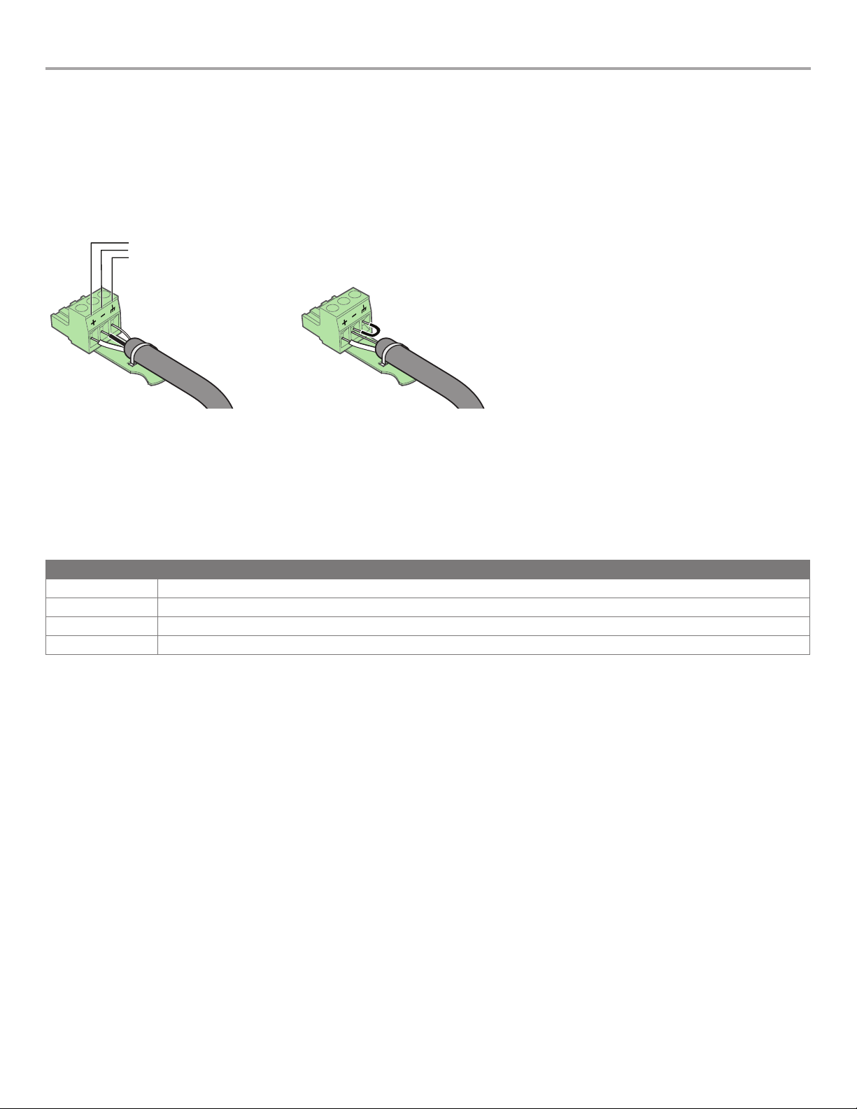
Wiring Input Connectors
The balanced line-level analog inputs utilize 3-pin terminal block connectors (Phoenix Contact
®
#1776168, supplied). Terminal descrip-
tions are printed directly on the connectors for convenience. For balanced inputs, strip the wire ¼ inch (6 mm) and connect to the
respective positive, negative, and ground terminals as indicated on the connector and in Figure 5. Tinned wires are not recommended.
For unbalanced inputs, the connector should be wired with the negative and ground/shield terminals, connected with a jumper wire
(not supplied). To reduce the occurrence of ground loop noise, it is recommended that the input cable shield be joined with the ground
terminal at only one device - at the source output connector or at the amplifier input connector. You can use the supplied tie-wraps to
help secure the input cables.
Figure 5. Balanced and unbalanced connectors (jumper not supplied)
Positive terminal
Negative terminal
Ground terminal
Balanced connection Unbalanced connection
Wiring Output Connectors
PowerMatch
®
amplifiers feature QuadBridge
™
technology which provides the flexibility to reconfigure each amplifier output. On a single
output connector, amplifier power can be allocated between 1 and 4 output channels for low impedance loudspeaker loads or up to 2
output channels for high impedance (70V and 100V) loudspeaker loads. A combination of high/low impedance loads and a mix of power
levels can be configured through the front panel interface or using ControlSpace
®
Designer™ software. The following table describes the
behavior of the four available output modes:
Mode Description
Mono
Each channel operates independently, and will drive 2 to 16 Ω loads
V-Bridge
Channel pairs are combined to deliver 2x voltage and will drive high impedance (70V or 100V) and 4 to 8 Ω loads
I-Share
Channel pairs are combined to deliver 2x current, and will drive 2 Ω loads
Quad
Two channel pairs are combined to deliver 2x voltage and 2x current while driving high impedance (70V or 100V) or 4 Ω loads
4-channel amplifiers (PM4500, PM4250) use a single loudspeaker output connector. 8-channel amplifiers (PM8500, PM8250) split total
amplifier power across two output connectors. In the case of the PM8500 which has a maximum rated power of 4000 watts, power is
split where 2000 watts is available at each output connector.
Each loudspeaker output utilizes a high-current, 8-pin locking terminal block connector (Phoenix Contact
®
COMBICON
®
Part #1778120,
supplied) that accept cables from 10 to 24 AWG (5.3 - 0.2 mm
2
) in diameter.
Note: Use Class 2 wiring for speaker connections.
To wire the output connector:
1. Strip the insulation off each speaker wire to expose 3/8" (10 mm) of bare conductor.
2. Insert each wire into the correct terminal on the block connector. Use a small Phillips size 1 (or appropriate) screwdriver to secure
the wire.
3. Firmly press the block connector into the receptacle on the amplifier until the left and right latches snap into place.
To detach the block connector from the amplifier, slide the two orange release tabs toward the amplifier to release the locking tabs.
Once released, pull the terminal block connector from the amplifier.
Warning: While the amplifier does self-protect under most improper output conditions, misconfiguration of loudspeaker mode and
incorrect connection of loudspeakers could damage connected loudspeakers and/or amplifier.
COMBICON is a registered trademark of Phoenix Contact GmbH & Co.
Phoenix Contact is a registered trademark of Phoenix Contact GmbH & Co.
Loading ...
Loading ...
Loading ...