Loading ...
Loading ...
Loading ...
22
Maintenance + Care
1. Keep the tool’s air vents unclogged and clean at all times.
2. Remove dust and dirt regularly. Cleaning is best done with
a rag or brush.
4. Never use caustic agents to clean plastic parts.
Troubleshooting
mWARNING! Always remove the battery before
performing any adjustments, maintenance, or repairs to your
cordless pole blower.
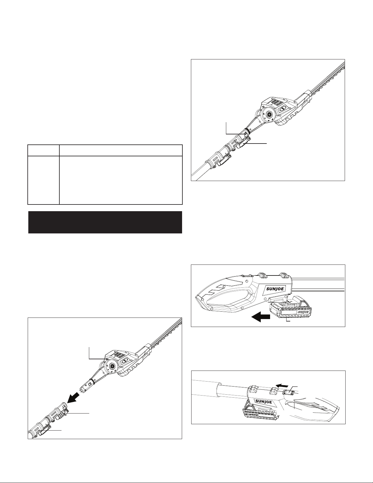
Assembly
Connecting to the Telescoping Pole
The hedge trimmer head comes fully assembled. To use the
machine as a pole hedge trimmer, connect the hedge trimmer
head with the telescoping pole as indicated below.
1. Open the assembly lock on the telescoping pole, and
push the hedge trimmer head into the opening on the end
of the pole (Fig. 36).
2. When the lock tabs snap in, lock back the assembly lock,
and the pole hedge trimmer will be ready to use (Fig. 37).
3. To remove the hedge trimmer head, release the On/O
switch and remove the battery. Unlock the assembly lock.
Push the lock tabs on both sides, and pull the hedge
trimmer head out (Fig. 37).
Operation
Starting and Stopping
1. Slide the battery into the battery compartment until it
clicks to lock it into position (Fig. 38).
2. To turn the pole hedge trimmer ON, push and hold the
safety lock switch (located on the handle) forward with
your thumb and then squeeze the On/O switch with
your ngers. Once the tool is running, you can release the
safety lock switch (Fig. 39).
3. To turn the tool OFF, release the On/O switch (Fig. 39).
Problems Corrective Action
Motor fails
to start
when switch
is turned
on.
• Check that you have inserted the battery properly
and the battery has enough power to work.
• Make sure that you fully depress, push forward
and hold the safety lock switch before squeezing
the ON/OFF trigger switch.
Pole Hedge Trimmer
Fig. 36
Hedge trimmer head
Assembly lock
Telescoping pole
Fig. 37
Lock tab
Assembly lock
Fig. 38
Battery
Fig. 39
On/O switch
Safety lock
switch
Loading ...
Loading ...
Loading ...