XML009-1
INSTRUCTION MANUAL
For 42-75" TV
If you have any questions along the way, just give us a call
1-800-460-0956 or mail to [email protected].
We’re ready to help!
R
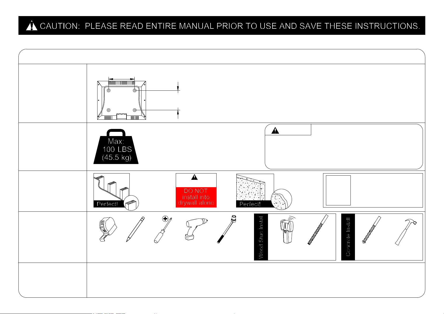
Before getting started, let’s check below lists to make sure it is just right for you!
2
3
4
5
2
Does your TV
(including accessories)
weigh MORE than
100 lbs. (45.5 kg)?
What is your
wall made of?
Do you have
all the tools
needed?
(NOT INCLUDE)
Tape
Measure
CAUTION
Pencil
Screw
driver
Electric
Drill
Drywall with
wood studs?
CAUTION:
CAUTION: DO NOT exceed the maximum weight
indicated. This mounting system is intended for use only
with the maximum weights indicated. Use with products
heavier than the maximum weights indicated may result
in collapse of the mount and its accessories, causing
possible injury.
Solid concrete
?
1/2 in.
(13 mm)
Socket
Wrench
Stud
Finder
7/32 in.
(5.5 mm)
Wood
Drill Bit
● This product is designed for use in wood stud, solid concrete walls - DO NOT install into drywall alone
● The wall must be capable of supporting five times the weight of the TV and mount itself
● Do not use this product for any purpose not explicitly specified by manufacturer
● Manufacturer is not responsible for damage or injury caused by incorrect assembly or use
Unsure?
Call Customer Service:
1-800-460-0956
3/8 in.
(10 mm)
Masonry
Drill Bit
Hammer
1
Check your TV
VESA is within
Min and Max size
No? This mount is NOT compatible.
Yes? Perfect !
MAX:600mm/23.62"
(MIN:100mm/3.94")
MAX:400mm/15.74"
(MIN:100mm/3.94")
No? Perfect – you may continue.
Yes? This mount is NOT compatible.
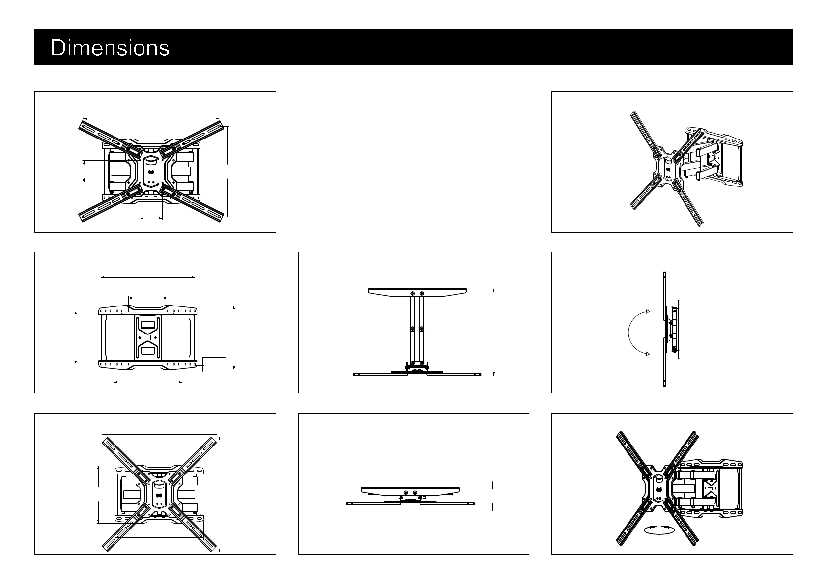
TV INTERFACE
3-D
WALL PLATE
FULLY ASSEMBLED MOUNT TOP VIEW - RETRACTED
SIDE VIEW
TOP VIEW - EXTENDED SIDE VIEW
3
+5°
-15°
+45° -45°
417mm
[16.42in]
173mm
[6.82in]
304mm
[11.97in]
285mm
[11.22in]
236mm
[9.29in]
9mm
[0.35in]
565mm
[22.24in]
565mm
[22.24in]
435mm
[17.13in]
285mm
[11.22in]
76mm
[2.99in]
386mm
[15.20in]
600mm
[23.62in]
400mm
[15.75in]
100mm
[3.94in]
100mm
[3.94in]
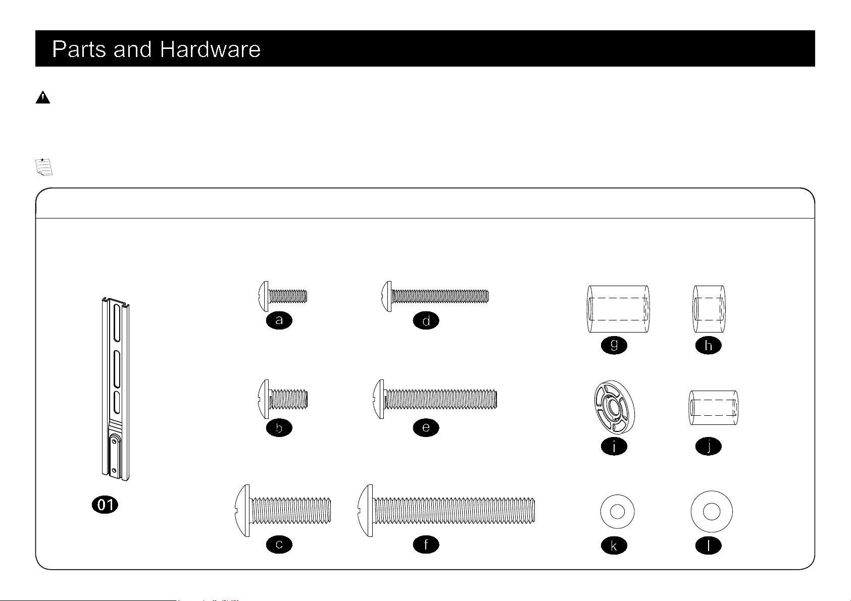
WARNING: This product contains small items that could be a choking hazard if swallowed. Before starting assembly, verify all parts
are included and undamaged. If any parts are missing or damaged, do not return the damaged item to your dealer; contact
Customer Service.
Never use damaged parts!
NOTE: Not all hardware included will be used.
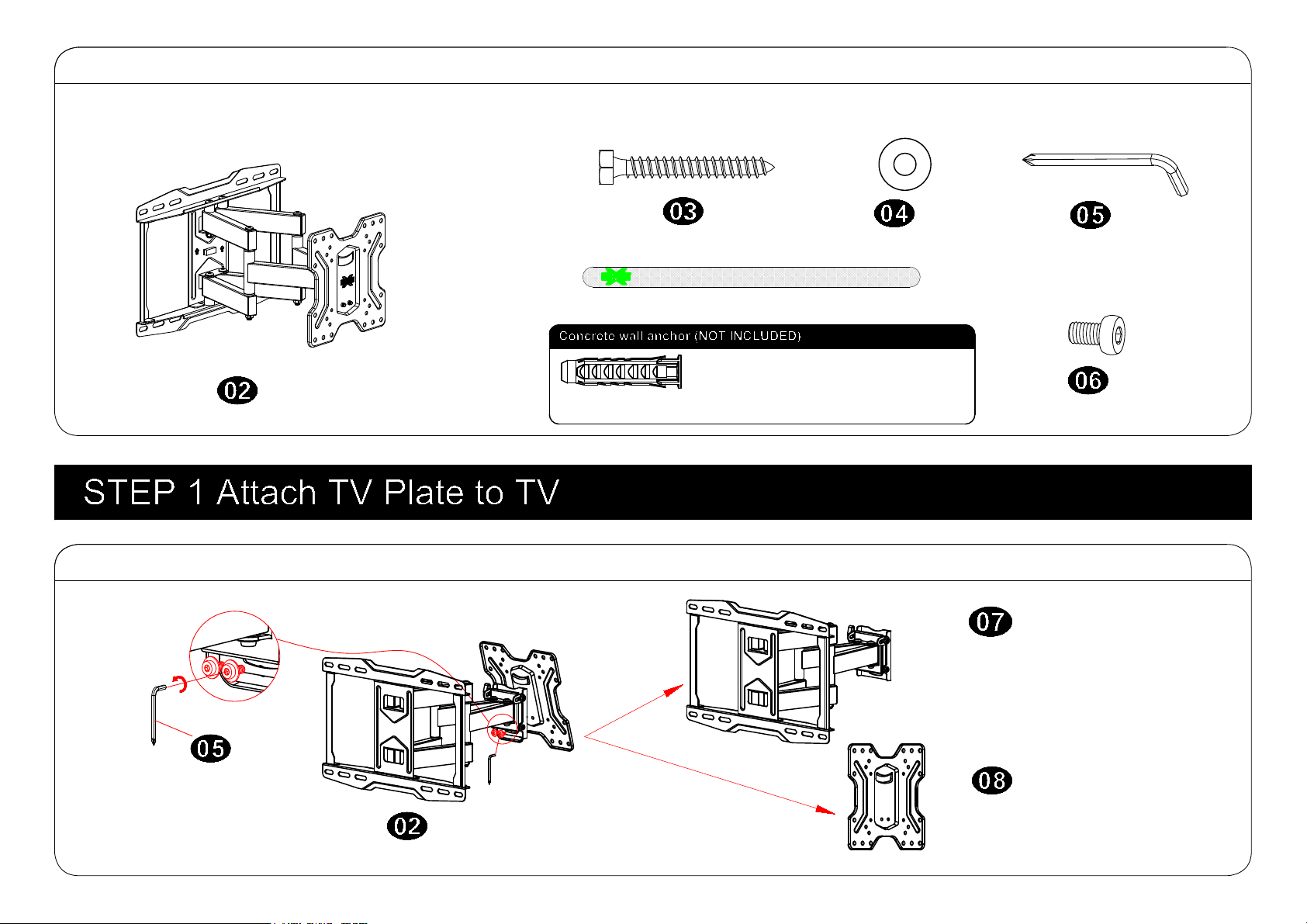
4
Parts and Hardware for STEP 1
Extenders
x4
Spacers
TV Screws
M4x12mm
M6x12mm
M8x25mm
M4x30mm
M6x35mm
M8x45mm
x4 x4
x4 x4
x4
x4
M6x17mm
M8x22mm
M4
M6
10mm
2.5mm
Washers
x4
x4
x4
x8
x4
x4
Lag Bolt
M8 Washer
x4
x4
Wall Plate Unit
x1
Parts and Hardware for STEP 2
1-1 Disassemble Wall Plate Unit into Two Pieces
5
Wall plate
TV plate
Allen Key
x1
M6x8mm Bolt
x8
Contact us at telephone 1-800-460-0956 (USA)
or mail to [email protected]. to have
these additional pieces shipped directly to you.
Concrete Wall Anchor
4pcs
Velcro x3
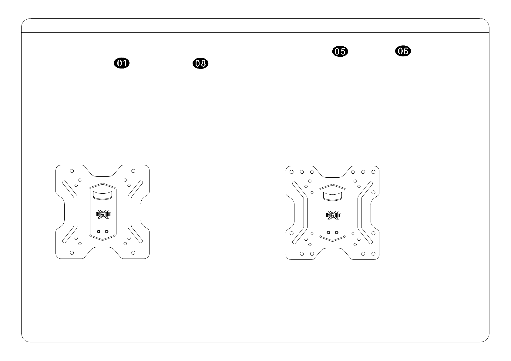
6
1-2
Choose Correct Configuration Per VESA Size on the Back of Your TV.
150X150
⑤
① 100X100
② 100X200
③ 200X100
④ 200X200
①①
① ①
② ②
② ②
③③
③ ③
④④
④ ④
⑤ ⑤
⑤ ⑤
If your TV VESA size is bigger than 200x200, you must use allen key and bolts to attach
4pcs of extenders onto TV plate .
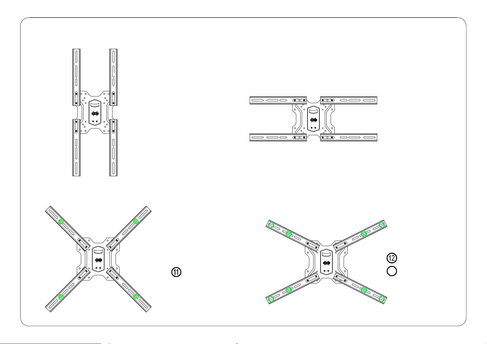
7
200X400
600X400
400X200
300X300
⑧
⑦
⑥
200X300
300X200
⑨
1 2
400X300
1 3
⑥
⑥
⑥
⑥
⑦
⑦
⑦
⑦
⑧
⑧
⑧
⑧
⑨⑨
⑨⑨
⑩
⑩ ⑩
⑩ ⑩
11
11
11
11
400X400
11
1 21 2
1 21 2
1 31 3
1 31 3
8
M8
M6
M4
1-3 Select TV Screws
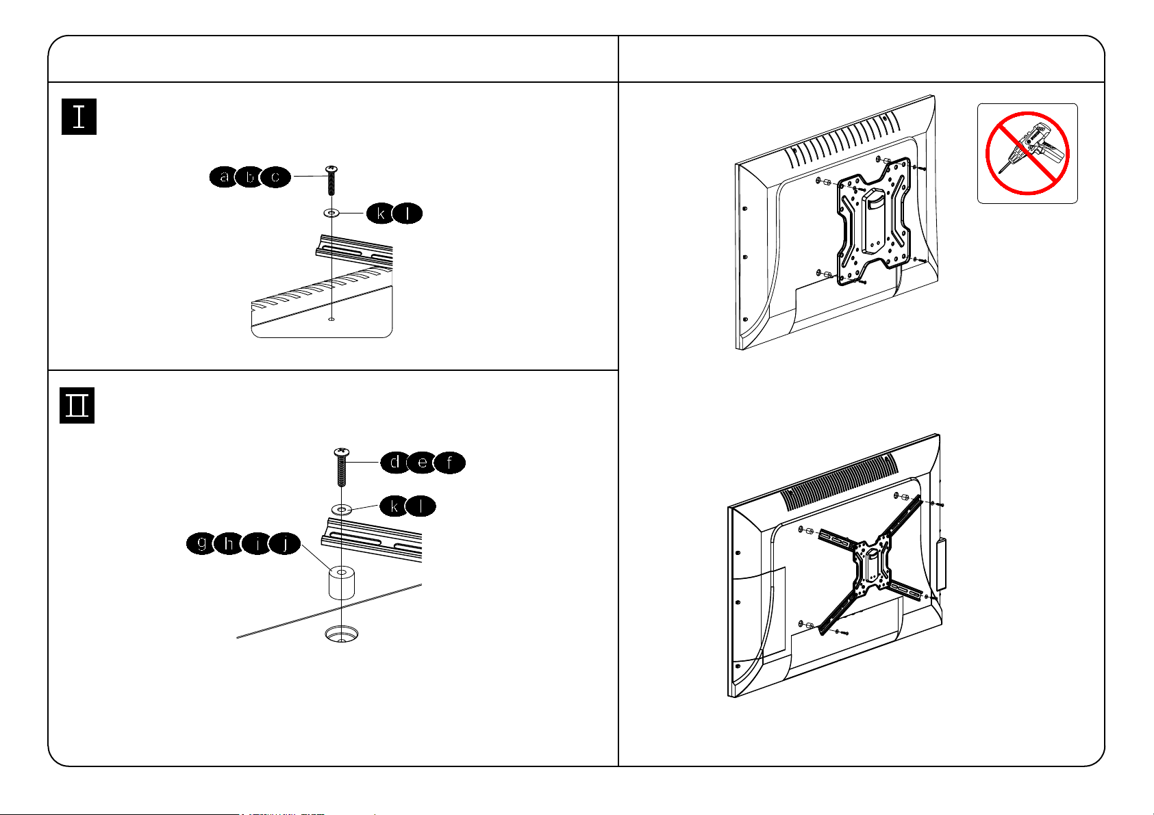
VESA ≤ 200mm x 200mm
200mm x 200mm < VESA ≤ 600mm x 400mm
9
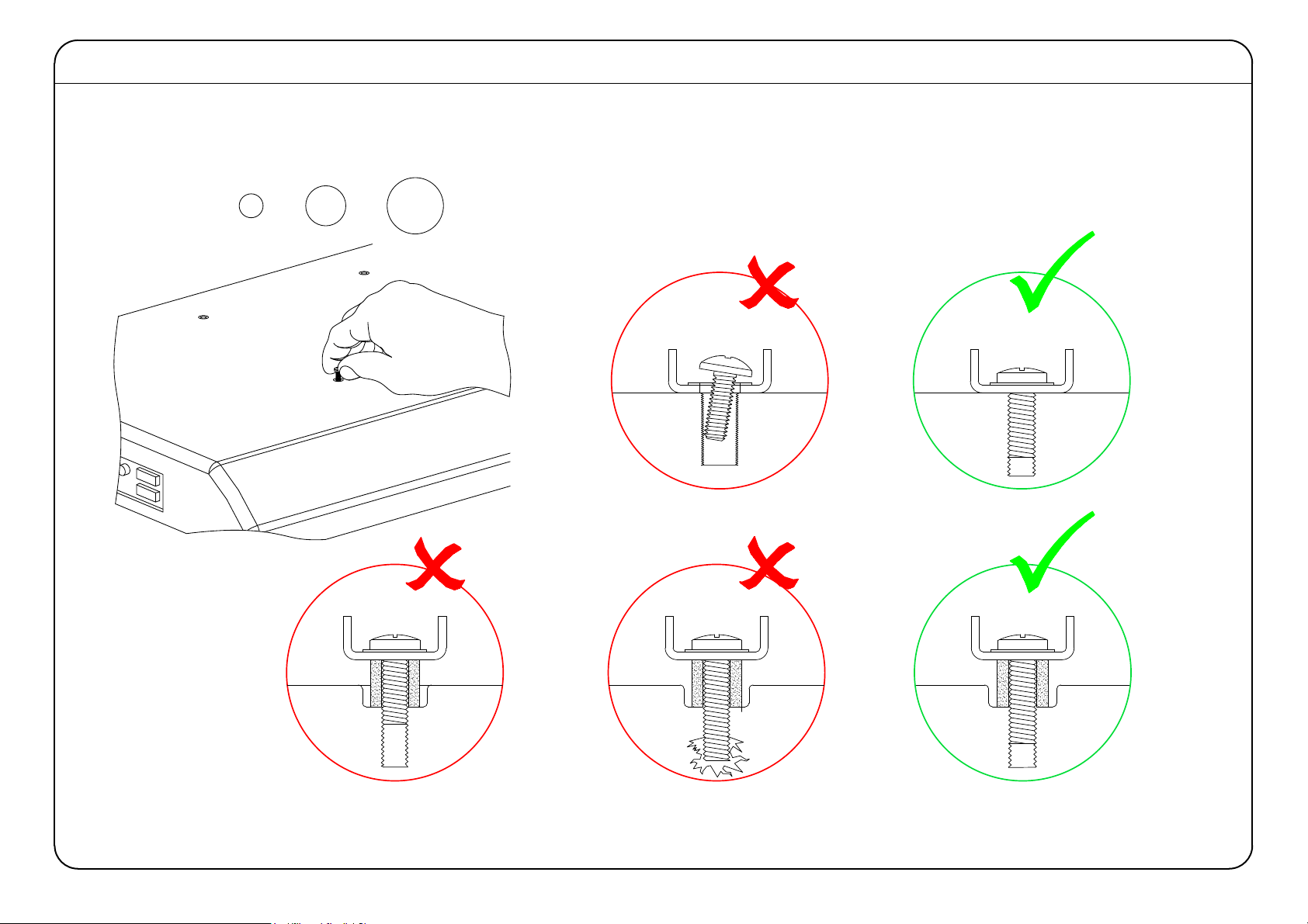
Tips: If you need to combine M6/M8(c/e/f) screws with
2.5mm spacers( i ), you have to remove the inner circle.
Yes, choose suitable screws, washers and spacers.
1-5
Attach the TV Plate
No!
No, choose suitable screws and washers.
1-4 Need Spacer?
CAUTION: Avoid potential personal injury or property damage!
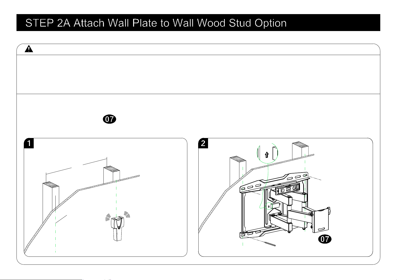
● Drywall covering the wall, must not exceed 5/8 in. (16 mm)
● Minimum wood stud size: common 2 x 4 in. (51 x 102 mm) nominal 1½ x 3½ in. (38 x 89 mm)
● Stud center must be verified
1. Locate your studs. Verify and mark the center of the stud by finding the stud edges using a thin nail,
or an edge to edge stud finder.
2. Position the wall plate at your desired height and line up the holes with your stud center line. Level
the wall plate and mark the hole locations.
Centre line
Again, find another wood stud
● Maximum horizontal space between fasteners: 16 in. (406 mm)
10
16"
Wall plate
UP
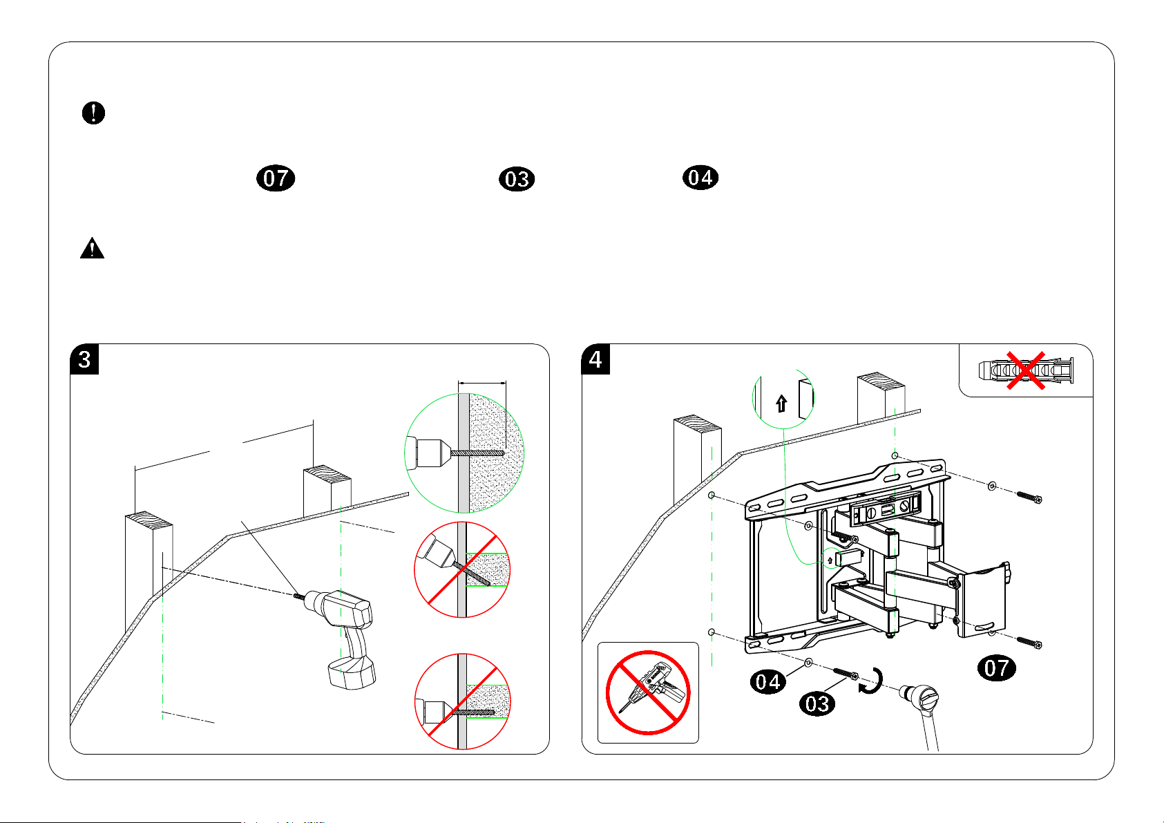
3. Drill pilot holes using a 7/32 in. (5.5 mm) diameter drill bit.
IMPORTANT: Pilot holes must be drilled to a depth of 2.5 in. (64 mm). Be sure to drill into the center
of the studs.
4. Install wall plate using four lag bolts and washers . Tighten the lag bolts only until they
are pulled firmly against the wall plate.
CAUTION: Improper use could reduce the holding power of the lag bolt.
DO NOT over-tighten the lag bolts.
Go to STEP 3 on PAGE 14.
2.5"(64mm)
7/32"
(5.5mm)
11
16"
Wall plate
UP
No!
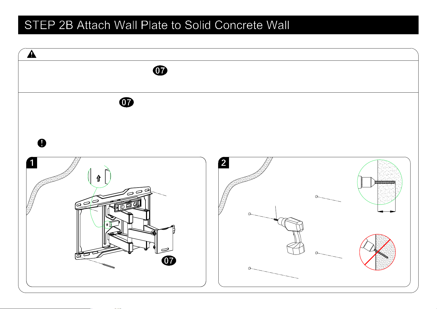
CAUTION: Avoid potential personal injury or property damage!
● Mount the wall plate assembly directly onto the concrete surface
● Minimum solid concrete thickness: 8 in. (203 mm)
1. Position the wall plate on the wall at your desired height. Level the wall plate and mark the
hole locations.
2. Drill four pilot holes using a 3/8 in. (10 mm) diameter masonry drill bit.
IMPORTANT: Pilot holes must be drilled to a depth of 2.5 in. (64 mm).
2.5"(64mm)
3/8"
(10mm)
12
Wall plate
UP
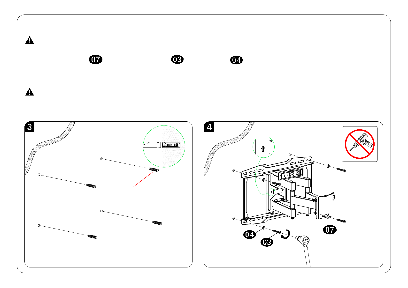
3. Insert four anchors.
CAUTION: Be sure the anchors are seated flush with the concrete surface.
CAUTION: Improper use could reduce the holding power of the lag bolt.
DO NOT over-tighten the lag bolts.
4. Insert wall plate using four lag bolts and washers .Tighten the lag bolts only until they are
pulled firmly against the wall plate.
13
Wall plate
UP
Please contact us at telephone 1-800-460-0956 (USA) or
mail to [email protected]. to have these
additional pieces shipped directly to you.
Concrete Wall Anchor
(Not included)
No!
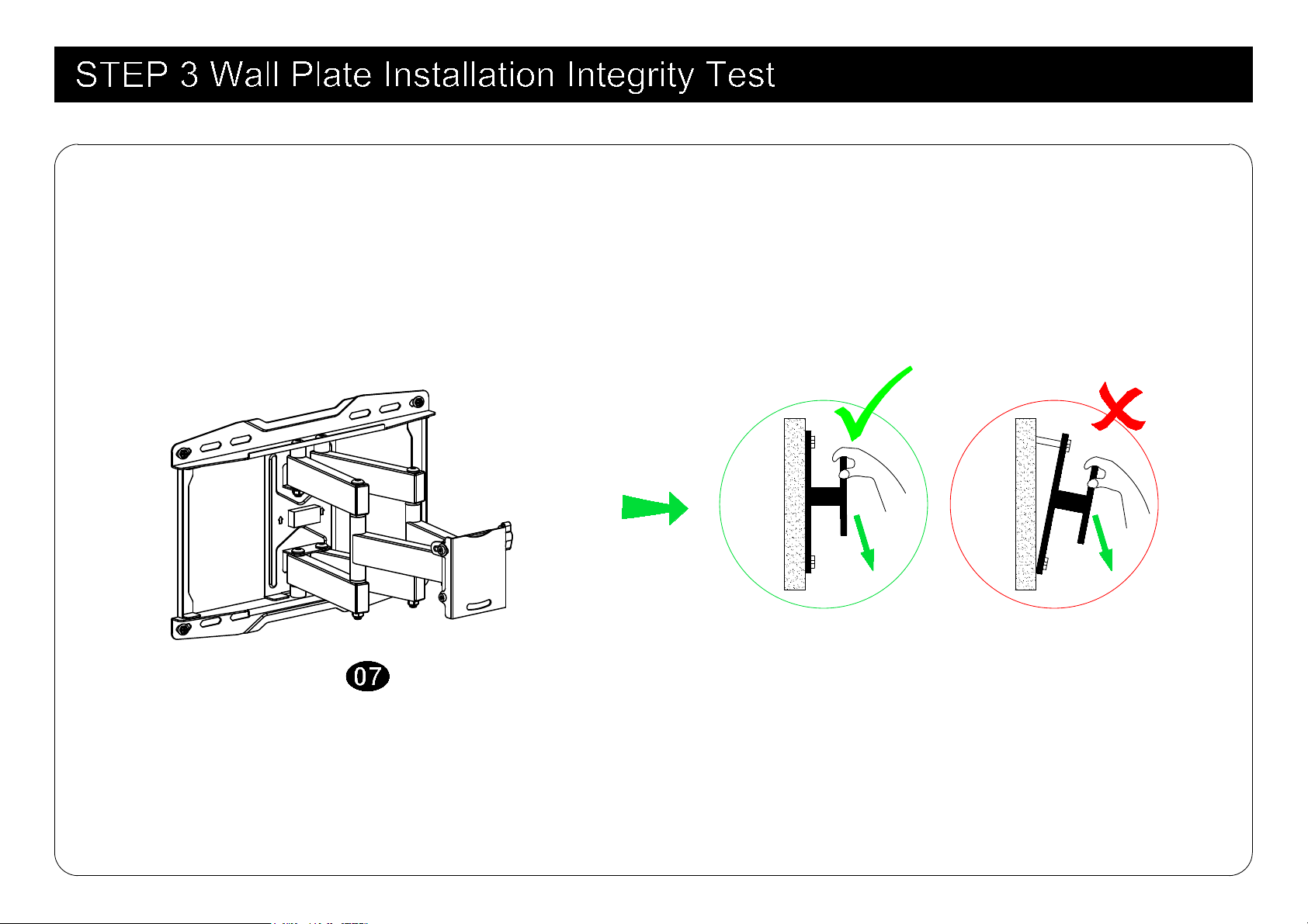
Before hanging TV, please try to pull the mount to make sure that it has been assembled on the wall
tightly.
100 LBS (45.5 KG)
14
Wall plate

TV
1 2
15
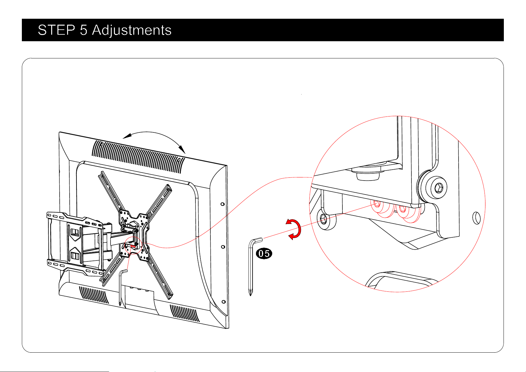
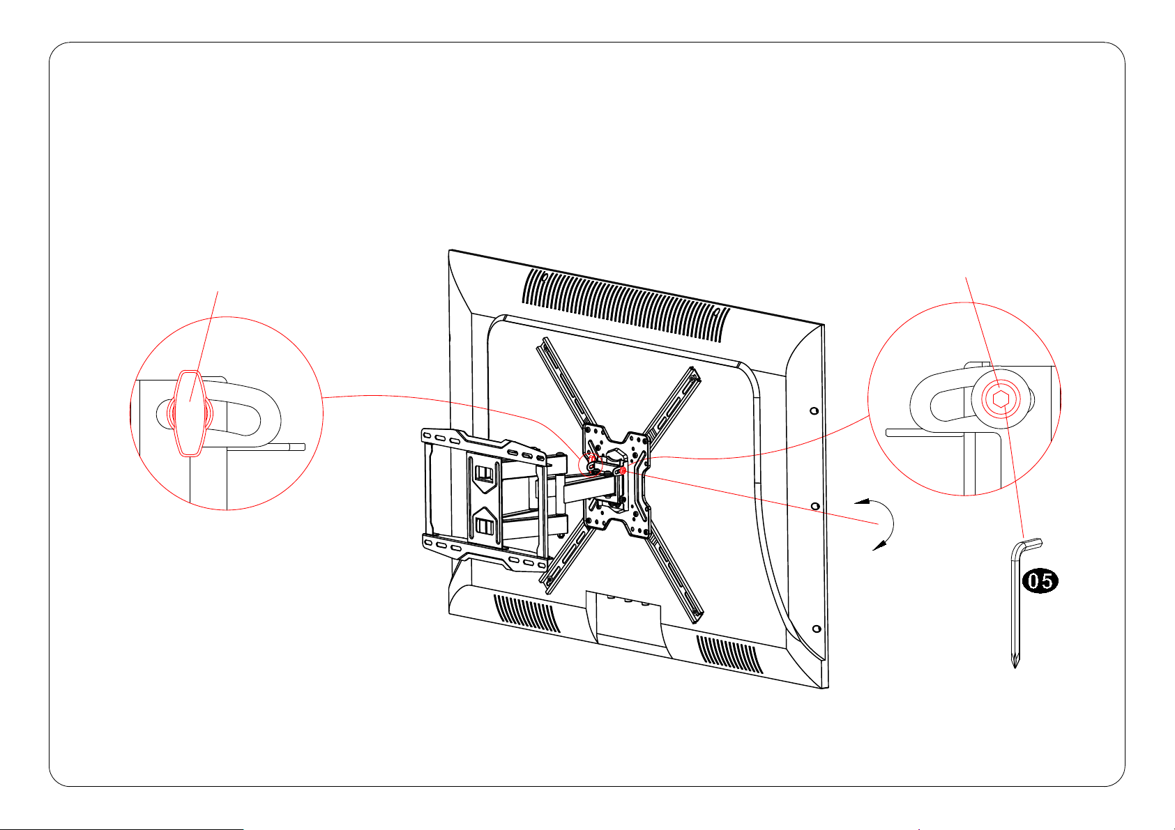
5-1 TV leveling adjustment (±4°):
Loosen 2 leveling bolts on the rear of TV plate by maximum 2 turns, adjust to level, and retighten to
secure.
16
Loosen
Tighten
±4°
5-2 Tilting angle adjustment (+5°/-15°):
Loosen handle and tilting bolt, adjust TV to your desired position, then tighten handle and tilting bolt.
-15°
+5°
Handle
Tilting bolts
17
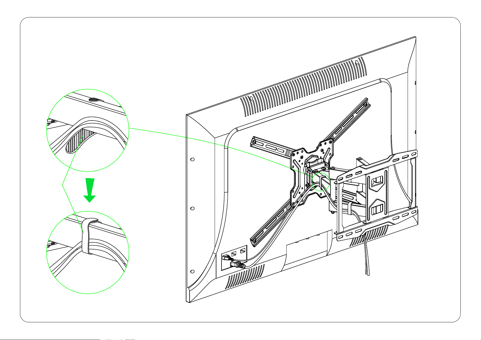
5-3 Cables manage:
Manage TV cables orderly and guide them through the velcros.
Velcro
18