Loading ...
Loading ...
Loading ...
6
Contents
Installation Considerations
Before beginning any installation, follow these simple rules:
1. Be sure to carefully read and understand the instructions
before attempting to install these speakers.
2. For safety, disconnect the negative lead from the battery
prior to beginning the installation.
3. For easier assembly, we suggest you run all wires prior to
mounting your speakers in place.
4. Use high quality connectors for a reliable installation and to
minimize signal or power loss.
5. Think before you drill! Be careful not to cut or drill into gas
tanks, fuel lines, brake or hydraulic lines, vacuum lines or
electrical wiring when working on any vehicle. If installation
in a boat, take care not to cut or drill through the main hull.
6. Never run wires underneath the vehicle. Running the wires
inside the vehicle or hull area provides the best protection.
7. Avoid running wires over or through sharp edges. Use
rubber or plastic grommets to protect any wires routed
through metal, especially the rewall.
• (1) Pair Wake Can Speakers
• (1) Pair Universal Clamps
• (4) Grommets
• (2) Spare Safety Inserts for
Screw Clamp
• (2) 1.5” to 2.5” Rubber
Clamp Inserts and
Stainless Hardware
• (2) 2.5” to 3” Rubber Clamp
Inserts and Stainless
Hardware
• (2) Speaker/RGB Wiring
Harnesses
• (1) Pair Stainless Grills
(installed)
• (1) Pair Sport Grills
• (1) Allen Bit For Speaker
Removal For Rotation
• (1) Safety Torx Wrench
Mounting
1. Determine where the speakers will be mounted. Be sure
that the mounting location has suicient clearance in all
direction for the speaker to swivel; conduct a full rotation to
ensure there is not obstruction.
2. Mark the locations on the underside of the mounting surface
for the speaker mount and wire harness. Drill a 7/16” for the
wire harness. If you are not using the wake can clamp or
do not running the wiring into the bar mounting the wake
can, use the speaker/RGB input on the back of the wake can
under the rubber plug
illus.-4.2
.
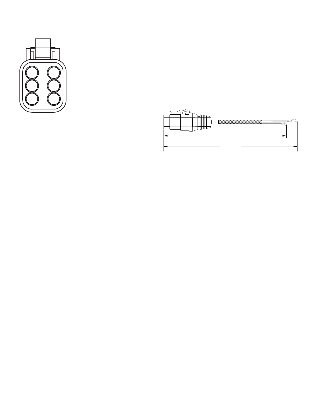
3. Insert the supplied grommet and feed the wire harness
through. Be sure to observe proper polarity when connecting
the wires. The speaker harness’s negative wire is the BLACK
18 AWG wire and the Positive is the RED 18 AWG wire in the 6
pin connector
illus.-4.3
.
4. Feed the speaker harness through the mount. Using the
supplied hardware, through bolt and tighten the mount
securing it.
5. Remove the plastic cover over the safety torx bolt to allow
access to loosen/tighten the wake can. Do this to adjust
the angle of the wake can, then tighten the safety torx bolt
to make sure it does not move. Replace plastic cover over
safety torx bolt
illus.-3.3
.
6. Rotate the RGB medalion on the rear of the wake can to
look like the image in
illus.-3.2
. This can be turned le or right
to align the medalion. You will hear/feel a clicking when you
rotate it.
7. If you need to rotate the speaker, remove the (6) screws
holding th speaker and grill on. Pull the speaker slightly
towards you and rotate it until it looks like
illus.-2.1
. Use the
predrilled holes to reinstall the speaker
illus.-3.1
.
Installation
1 - BLACK (Speaker Negative, 18 AWG)
2 - YELLOW (12V + Input, 22 AWG)
3 - RED (Speaker Positive, 18 AWG)
4 - GREEN (Ground Input, 22 AWG)
5 - RED (Ground Input, 22 AWG)
6 - BLUE (Ground Input, 22 AWG)
Included with speakers
Connector is DEUTSCH™/Amphenol style DT06-4S
(1)
(3)
(5)
(2)
(4)
(6)
13”
(330mm)
14”
(355mm)
illus.-4.3
illus.-4.4
Loading ...
Loading ...
Loading ...