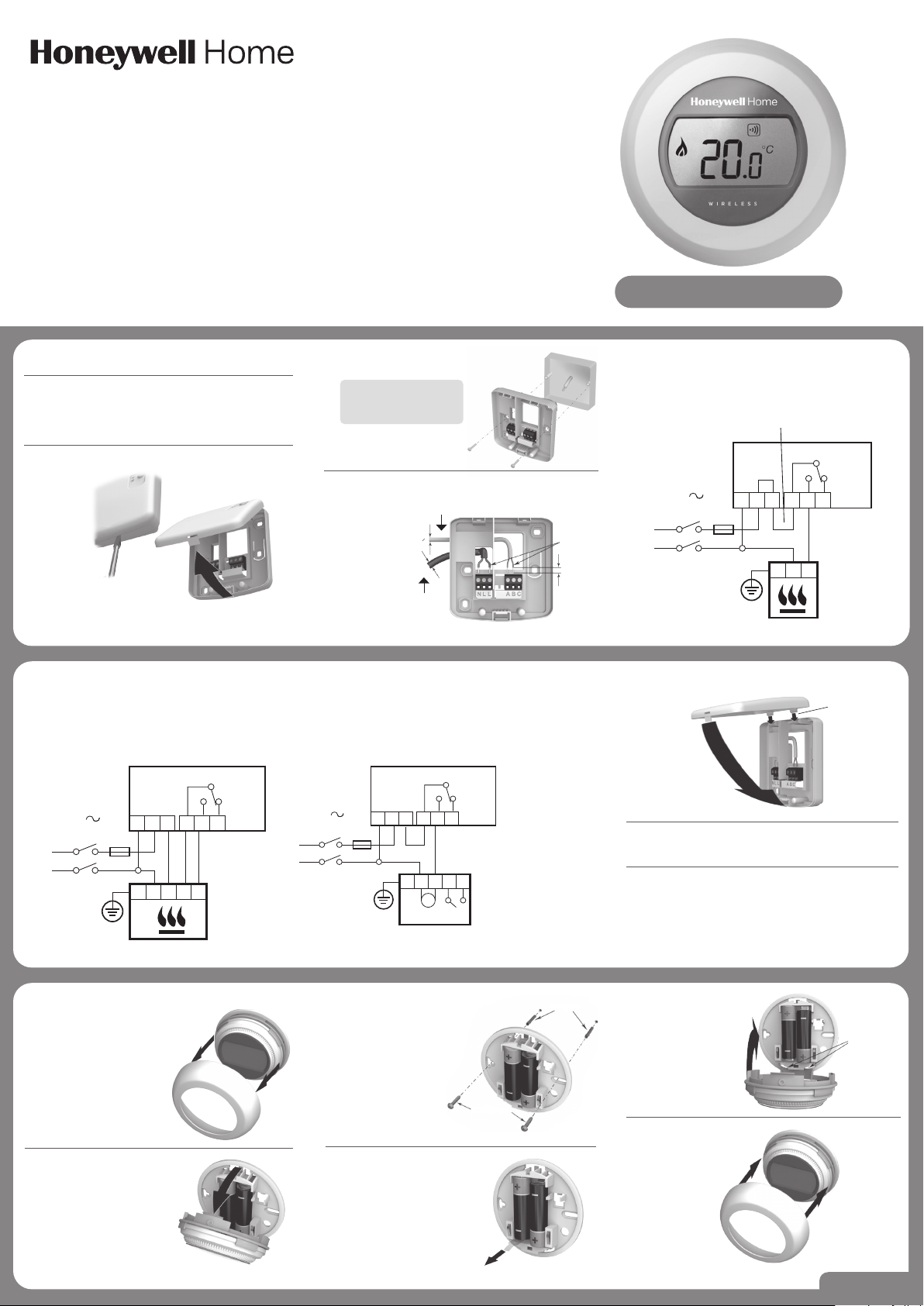
5.2 Wiring for a boiler that requires a
permanent live (a typical Combi boiler).
This can be used for boilers with low voltage
or 230Vac room thermostat inputs. Please
check manufacturer’s instructions.
EN
|
Installation Guide
Note: the plugs and
mounting screws
are supplied.
1. Disconnect the mains power from
the Heating Appliance.
To ensure your safety, always make sure mains
power is switched off before accessing wiring.
3. Mount the wiring plate
to the wall or wallbox.
4. Connect the Boiler Relay wiring.
2. Remove the wiring plate from the Boiler Relay.
Step 1
Use a
screwdriver to
unclip the cover
from base.
Step 2
Hinge the cover
upwards to remove.
5.1 Wiring for a basic boiler (not
requiring a pump overrun).
The Boiler Relay powers the boiler live input.
230V
50-60Hz
<5A
N L
N L
L
BDR91
Place link here
A-B:5(3)A
A-C:5(3)A
A B C
L
N
Installation Instructions
Power supply
from
fused spur
To heating appliance
1,5-2,5 mm
2
max 6 mm
>7 mm 0
<7 mm 0
Place link here
230V
50-60Hz
<5A
N L L
BDR91
A-B:5(3)A
A-C:5(3)A
A B C
L
N
N L
5.3 Wiring for a two-port zone valve.
230V
50-60Hz
<5A
N L L
BDR91
V4043H
A-B:5(3)A
A-C:5(3)A
A B C
L
N
BL BR
M
GR O
G
/
Y
G/Y: Green/Yellow
Earth wire
BL: Blue Motor
Neutral
BR: Brown Motor Live
GR: Grey End
switch (if used)
Permanent Live
O: Orange End
switch (If used).
In wired system
this typically
feeds the boiler.
7. Reconnect the mains power to
the Heating Appliance.
8. Locate the thermostat.
• Away from draughts
• Away from heat sources
• Away from direct sunlight
• Positioned about 1.2m – 1.5m from the floor
6. Attach the Boiler Relay to the wiring plate.
Step 1
Locate hinges
Step 2
Hinge the cover
downwards and
click into place.
10. Unclip the mounting plate.
Press the top of the
thermostat downwards, pull
it loose and tilt forwards.
9. First remove the dial.
12. Remove the protective tab
between the batteries.
11. Mount directly to the wall.
The plugs and mounting
screws required
are supplied.
Plugs
Screws
14. Replace the dial.
13. Attach the
thermostat to the
mounting plate.
Step 1
Locate hinges
Step 2
Hinge upwards
and click
into place
32300951-013 B
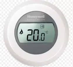
Y87RFC
Connected Single Zone Thermostat
Please refer
to wiring
diagram
(right).
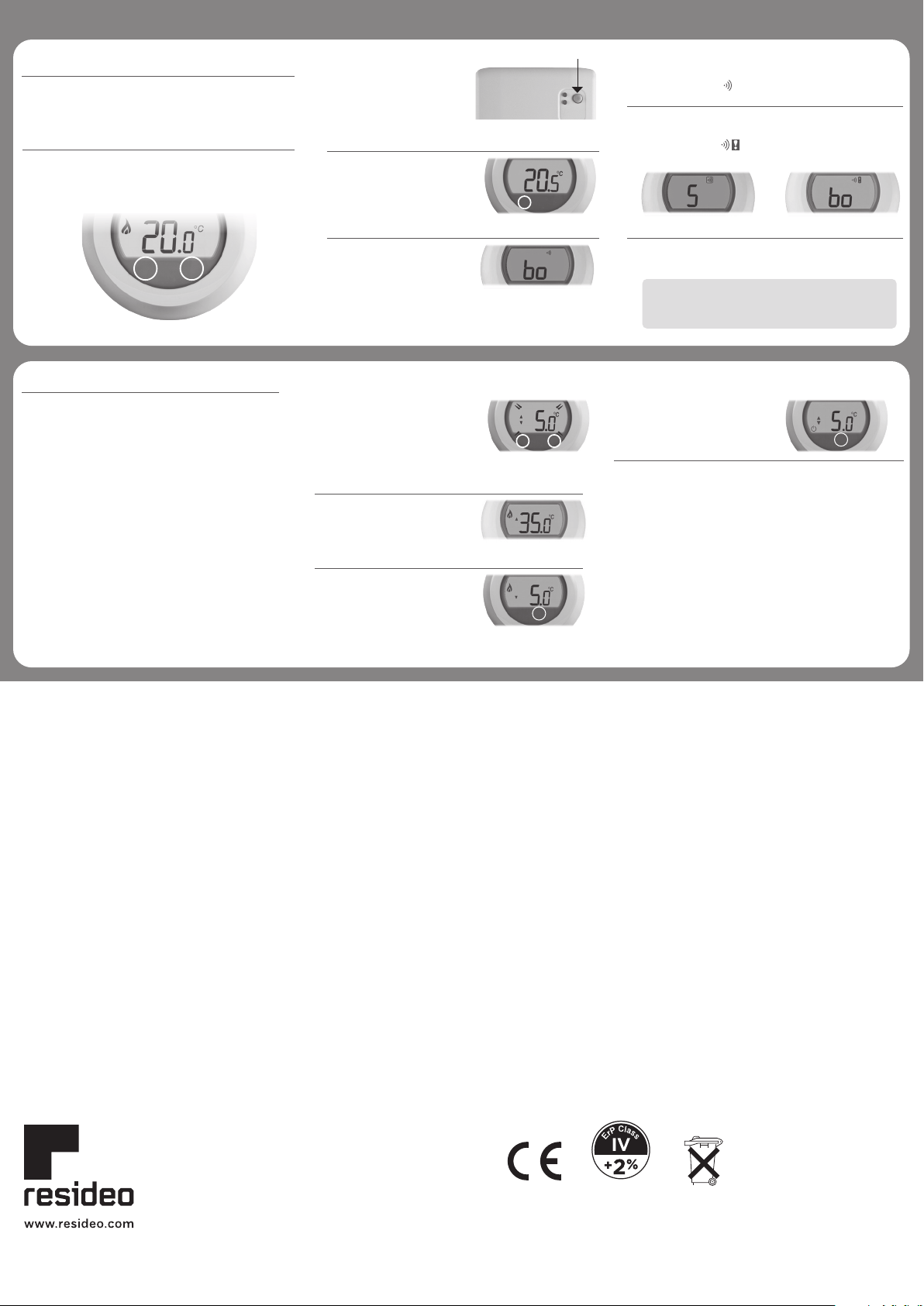
Binding to the Boiler Relay
The Thermostat is supplied ready to install, binding is
only required if the Thermostat and Boiler Relay are
purchased separately.
2. You can now bind the
Thermostat. Touch and
hold on the left touch
zone for approximately
10 seconds.
3. The screen for binding
the Boiler Relay is
now displayed.
Successful binding Failed binding
1. First, set the Boiler
Relay into binding
mode by holding down
the BIND button for 5
seconds, until the red
LED flashes 0.5 seconds
on 0.5 seconds off.
Press here
4. When the symbol ‘bo’ is flashing, briefly touch
the left touch zone to send the binding signal, at
which point the symbol will flash several times.
5. If binding has been successful the number
indicates the signal strength (1 = min to 5 = max).
If binding fails, appears on
screen. Please try again.
6. The red LED on the Boiler Relay will turn
off when binding has been successful.
Touch zones.
There are two touch zones just below the thermostat
display, which are used to access menus and functions.
10s
Installation Menu
The Thermostat has an Installation Menu that
is used to set the minimum and maximum
temperature limits and the off temperature setting.
Maximum and minimum temperatures:
The maximum temperature you can set your
thermostat to is 35°C and the minimum is 5°C.
The off temperature:
If the thermostat is operated remotely, this
is the temperature value that is used when
it is switched off from the remote app.
4. Touch the left touch zone to
display the off temperature
setting. Change this using
the setting ring as before.
5. The Installation Menu closes
automatically 10 seconds
after the last action.
2. The maximum temperature
limit is now displayed. The
setting can be changed using
the setting ring. There is no
need to confirm the value.
3. While this setting is flashing,
touch the left touch zone
briefly to display the
minimum temperature limit.
This can also be changed
using the setting ring.
1. Rotate the setting ring fully
to the left until the minimum
value is shown. When
the value starts flashing,
touch and hold on both left
and right touch zones for
approximately 10 seconds.
Activate the Installation Menu as follows:
10s 10s
Note: binding can be cancelled from the binding
screen by touching and holding on the left
touch zone for approximately 10 seconds.
Printed in EU.
(EU) 811/2013
© 2020 Resideo Technologies, Inc. All rights reserved.
The Honeywell Home trademark is used under license from Honeywell International Inc.
This product is manufactured by Resideo Technologies, Inc. and its affiliates.
Pittway Sarl, Z.A. La Pièce 4,
1180 Rolle, Switzerland
Country of origin : UK
For support:
Resideo
200 Berkshire Place
Winnersh Triangle, Berkshire
RG41 5R
Phone: 0300 130 1299
Approvals:
Hereby, Pittway Sarl declares that the radio equipment type Y87RF is in
compliance with Directive 2014/53/EU. The full text of the EU declaration of
conformity is available at the following internet address: https://hwllhome.co/DoC
RF (868MHz): Receiver Category 2, Max RF Power 25mW, 868–868.6MHz (868.3MHz)