Loading ...
Loading ...
Loading ...
44
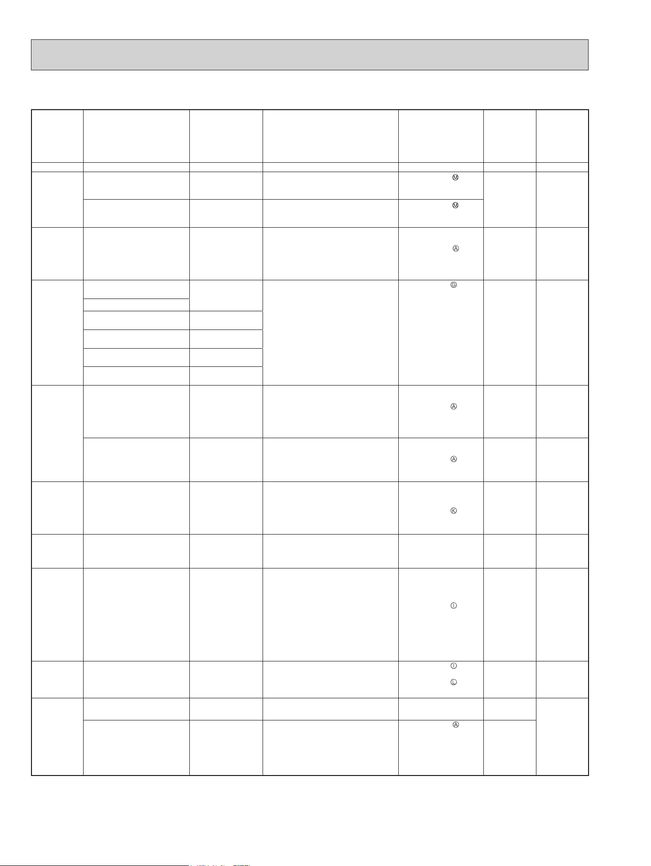
3. Table of outdoor unit failure mode recall function
The upper
lamp of the
OPERATION
INDICATOR
lamp
(Indoor unit)
Abnormal point
(Failure mode/protection)
LED indication
(Outdoor P.C. board)
Condition Remedy
Indoor/outdoor
unit failure
mode recall
function
Outdoor unit
failure mode
recall function
OFF None (Normal) — — — — —
1-time blink
2.5 seconds
OFF
Indoor/outdoor
communication, receiving
error
—
Any signals from the inverter P.C.
board cannot be received normally for
3 minutes.
•Refer to 10-5.
How
to check miswiring and
serial signal error.
○ ○
Indoor/outdoor
communication, receiving
error
—
Although the inverter P.C. board
sends signal "0", signal "1" has been
received 30 consecutive times.
•Refer to 10-5.
How
to check miswiring and
serial signal error.
2-time blink
2.5 seconds
OFF
Outdoor power system
—
Overcurrent protection cut-out
operates 3 consecutive times within
1 minute after the compressor gets
started.
•
Reconnect
connectors.
•
Refer to 10-5.
"How
to check inverter/
compressor".
•
Check stop valve.
○ ○
3-time blink
2.5 seconds
OFF
Discharge temperature
thermistor
1-time blink every
2.5 seconds
Thermistor shorts or opens during
compressor running.
•
Refer to 10-5.
"Check of outdoor
thermistors".
Defective outdoor
thermistors can be
identied by checking
the blinking pattern of
LED.
○ ○
Defrost thermistor
Fin temperature thermistor 3-time blink
2.5 seconds OFF
P.C. board temperature
thermistor
4-time blink
2.5 seconds OFF
Ambient temperature
thermistor
2-time blink
2.5 seconds OFF
Outdoor heat exchanger
temperature thermistor
—
4-time blink
2.5 seconds
OFF
Overcurrent 11-time blink
2.5 seconds OFF
Large current ows into the power
module (IC700) (MUZ-GL09/12/15/18,
MUY-GL09/12/15/18)/ IGBT module
(IC700) (MUZ-GL24, MUY-GL24).
•
Reconnect
compressor connector.
•
Refer to 10-5.
"How
to check inverter/
compressor".
•
Check stop valve.
—
○
Compressor synchronous
abnormality (Compressor
startup failure protection)
12-time blink
2.5 seconds OFF
Waveform of compressor current is
distorted.
•
Reconnect
compressor connector.
•
Refer to 10-5.
"How
to check inverter/
compressor".
—
○
5-time blink
2.5 seconds
OFF
Discharge temperature
—
Temperature of discharge temperature
thermistor exceeds 241°F (116°C),
compressor stops.
Compressor can restart if discharge
temperature thermistor reads
212°F (100°C) or less 3 minutes later.
•
Check refrigerant
circuit and refrigerant
amount.
•
Refer to 10-5.
"Check
of LEV".
—
○
6-time blink
2.5 seconds
OFF
High pressure
—
Temperature indoor coil thermistor
exceeds 158°F (70°C) in HEAT
mode. Temperature defrost thermistor
exceeds 158°F (70°C) in COOL mode.
•
Check refrigerant
circuit and refrigerant
amount.
•
Check stop valve.
—
○
7-time blink
2.5 seconds
OFF
Fin temperature/ P.C. board
temperature
7-time blink
2.5 seconds OFF
Temperature of the n temperature
thermistor on the inverter P.C. board
exceeds 167 - 187°F (75 - 86°C) (MUZ-
GL09/12/15/18, MUY-GL09/12/15/18)/167
- 176°F (75 - 80°C) (MUZ-GL24, MUY-
GL24), or temperature of P.C. board
temperature thermistor on the inverter
P.C. board exceeds 162 - 185°F (72
- 85°C) (MUZ-GL09/12/15/18, MUY-
GL09/12/15/18)/158 - 167°F (70 - 75°C)
(MUZ-GL24, MUY-GL24).
•
Check around outdoor
unit.
•
Check outdoor unit air
passage.
•
Refer to 10-5.
"Check
of outdoor fan motor".
—
○
8-time blink
2.5 seconds
OFF
Outdoor fan motor
—
Outdoor fan has stopped 3 times in a
row within 30 seconds after outdoor
fan startup.
•
Refer to 10-5.
"Check
of outdoor fan motor".
Refer to 10-5.
"Check
of inverter P.C. board".
—
○
9-time blink
2.5 seconds
OFF
Non-volatile memory data 5-time blink
2.5 seconds OFF
Non-volatile memory data cannot be
read properly.
•
Replace the inverter
P.C. board.
○
○
Power module (IC700)
(MUZ-
GL09/12/15/18
, MUY-
GL09/12/15/18
)
IGBT module (IC700)
(MUZ-GL24, MUY-GL24)
6-time blink
2.5 seconds OFF
The interface short circuit occurs
in the output of the power module
(IC700) (MUZ-GL09/12/15/18, MUY-
GL09/12/15/18)/IGBT module (IC700)
(MUZ-GL24, MUY-GL24).
The compressor winding shorts circuit.
•
Refer to 10-5.
"How
to check inverter/
compressor".
—
NOTE: Blinking patterns of this mode differ from the ones of
TROUBLESHOOTING CHECK TABLE (10-3.).
OBH733J
Loading ...
Loading ...
Loading ...