Loading ...
Loading ...
Loading ...
Application Guide - 19
Design Worksheet, EdgeMax EM90 Systems
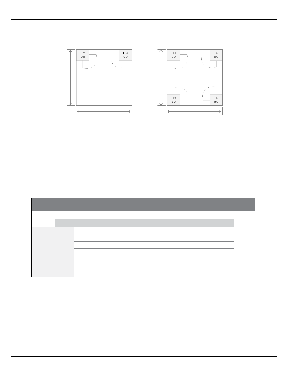
Step 5: Select the type of layout that will be used based on the Usable Throw Distance, and
the dimensions of the room where the system will be installed.
Step 6 (Amplifier Size): Calculate the required amplifier size. Use the Tap Chart below to
determine which loudspeaker tap is required for this design.
A. Locate the loudspeaker mounting height for this design.
B. Draw a line down to the desired maximum SPL.
C. Draw a horizontal line across the chart to read the required loudspeaker tap.
D. Calculate the required amplifier power:
E. Calculate the required amplifier size:
4x EM90 in Corners
EM
90
EM
90
EM
90
EM
90
2x Usable Throw Distance
2x Usable Throw Distance
2x EM90 in Corners
EM
90
EM
90
Usable Throw Distance
Usable Throw Distance
Number of
Loudspeakers
Required
Loudspeaker Tap
Power
Required
X
=
Power Required
Headroom Amplifier Size
X
=
1.25
Continuous SPL, EdgeMax EM90
Mount
Height
m 2.7 3.0 3.7 4.3 4.9 5.5 6.1 6.7 7.9 9.1
ft 9 10 12 14 16 18 20 22 26 30
TAP
2.5 94 92 89 87 85 83 82 81 79 78
dB
SPL
5 97 95 92 90 88 86 85 84 82 81
10 100 98 95 93 91 89 88 87 85 84
20 103 101 98 96 94 93 91 90 88 87
40 106 104 101 99 97 96 94 93 91 90
80 109 107 104 102 100 99 97 96 94 93
8 Ohm 111 109 106 104 102 100 99 98 96 95
NOTE: For designs where bass is a primary consideration, square rooms
with 4x EM90s will deliver more bass then 4x EM180s, due to the additional
wall‑boundary loading provided by the corner mounting.
Loading ...
Loading ...
Loading ...