PROFESSIONAL
EdgeMax
™
EM90 and EM180
In-Ceiling Loudspeakers
Application Guide

Application Guide - 2
Contents
EdgeMax Loudspeaker Overview . . . . . . . . . . . . . . . . . . . . . . . . . . . . . . . . 3
Comparison of In-Ceiling and Surface Mounted Loudspeaker Performance . . . . . . . . . . . 3
EdgeMax Loudspeaker Performance . . . . . . . . . . . . . . . . . . . . . . . . . . . . . 5
EdgeMax Design Considerations . . . . . . . . . . . . . . . . . . . . . . . . . . . . . . . . 6
Standard and Premium Coverage . . . . . . . . . . . . . . . . . . . . . . . . . . . . . . . . . . . 6
Maximum Room Dimension . . . . . . . . . . . . . . . . . . . . . . . . . . . . . . . . . . . . . . 6
Balancing SPL In Mixed EM90 and EM180 Systems . . . . . . . . . . . . . . . . . . . . . . . . . 8
EdgeMax Active Equalization . . . . . . . . . . . . . . . . . . . . . . . . . . . . . . . . . . . . . 9
Design Worksheet, EdgeMax EM180 & Mixed EM90/EM180 Systems . . . . . . . .10
Design Guidelines . . . . . . . . . . . . . . . . . . . . . . . . . . . . . . . . . . . . . . . . . . . .10
Design Worksheet . . . . . . . . . . . . . . . . . . . . . . . . . . . . . . . . . . . . . . . . . . . . 12
Design Worksheet, EdgeMax EM90 Systems . . . . . . . . . . . . . . . . . . . . . . . .16
Design Guidelines . . . . . . . . . . . . . . . . . . . . . . . . . . . . . . . . . . . . . . . . . . . .16
Design Worksheet . . . . . . . . . . . . . . . . . . . . . . . . . . . . . . . . . . . . . . . . . . . .18
Sample EdgeMax Conference Room Applications . . . . . . . . . . . . . . . . . . . 20
Small Conference Rooms . . . . . . . . . . . . . . . . . . . . . . . . . . . . . . . . . . . . . . . 20
Medium Conference Rooms . . . . . . . . . . . . . . . . . . . . . . . . . . . . . . . . . . . . . .21
Large Conference Rooms . . . . . . . . . . . . . . . . . . . . . . . . . . . . . . . . . . . . . . . . 21
For the latest documentation and technical information, please visit PRO.BOSE.COM.
Application Guide - 3
EdgeMax Loudspeaker Overview
EdgeMax Loudspeaker Overview
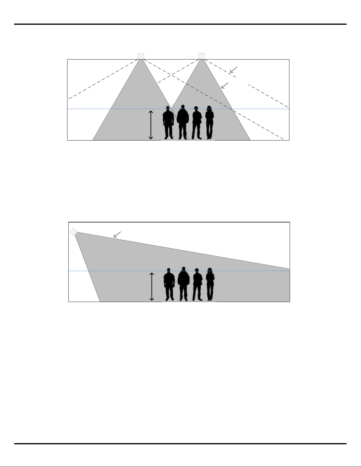
Comparison of In-Ceiling and Surface Mounted Loudspeaker Performance
Traditional in-ceiling loudspeaker designs are preferred in many cases as loudspeakers easily
blend into the environment due to their mounting location and flush appearance. Because in-
ceiling loudspeakers oer the best aesthetics they are the most common type of design for a
variety of applications.
However, many in-ceiling loudspeakers utilize a single transducer and deliver a conical
coverage pattern with a stated coverage angle, e.g. 120-degrees conical. This coverage angle,
however, is not representative for the higher frequencies, which is narrower, resulting in a
significant reduction in high frequency energy as you move o axis from the loudspeaker
location.
This design guide covers topics related to EdgeMax™ loudspeakers, and their use in specific
applications. Designed for in-ceiling mounting near wall-ceiling boundaries, EdgeMax
loudspeakers provide improved audio quality and coverage, while reducing the number
of required units, compared to conventional dome-tweeter ceiling speakers. EdgeMax
loudspeakers feature proprietary Bose® PhaseGuide® technology that combines the
room-filling coverage patterns typical of larger surface-mount speakers with the architect-
preferred aesthetics of in-ceiling models.
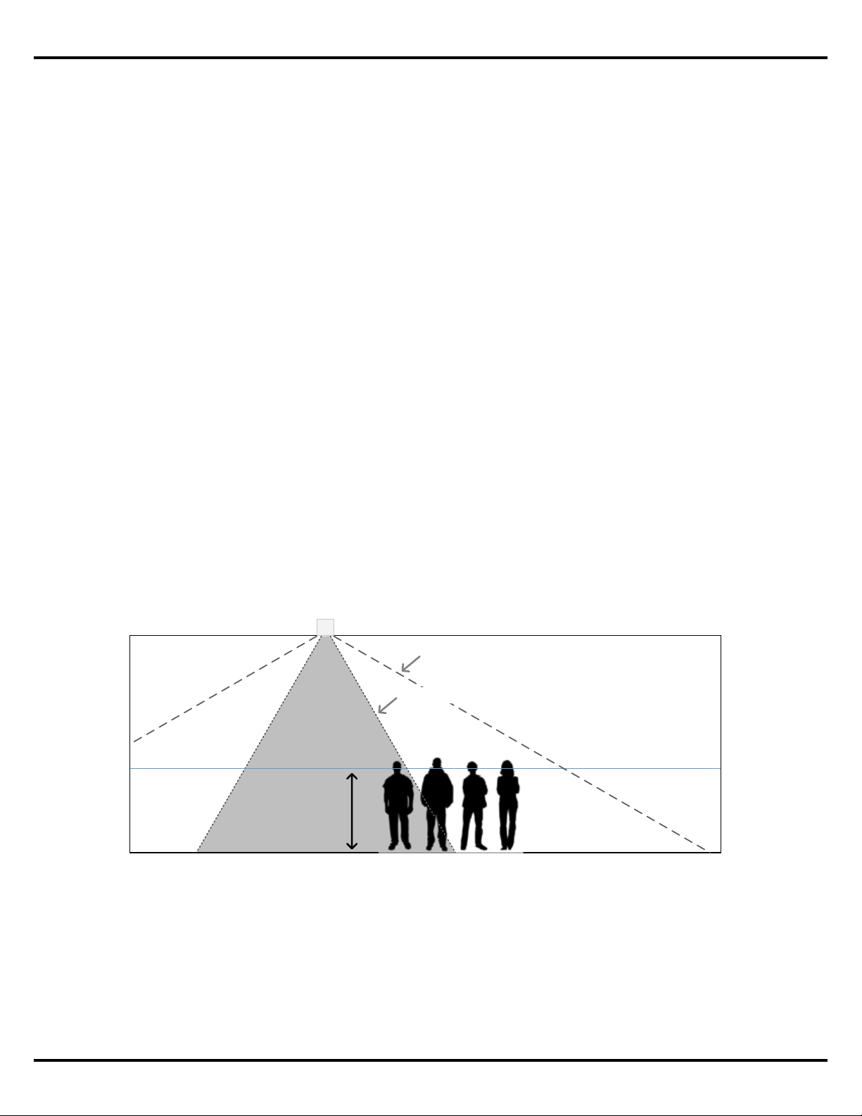
Conical Ceiling Loudspeaker
Average
Listener
Height
(1.5 m | 5 )
Published Coverage Angle
High Frequency Coverage Angle
Figure 1. Comparison between the published and typical high frequency coverage angles
for an in‑ceiling conical dispersion loudspeaker. Note that the shaded section represents the
area where a balanced frequency response will be delivered.
About
Application Guide - 4
EdgeMax Loudspeaker Overview
Surface-mounted loudspeakers do not oer the same aesthetic advantage, but are preferred
when consistent tonal balance across the coverage area is the primary design objective. This is
due to the physical nature of how surface-mounted loudspeakers project sound.
Despite these performance benefits, in-ceiling loudspeaker designs are still heavily preferred
due to the aesthetic preference of architects and interior designers looking to minimize the
appearance of loudspeakers.
Surface Mounted Loudspeaker
Average
Listener
Height
(1.5 m | 5 )
High Frequency Coverage Angle
Figure 3. Typical projection of a surface mounted loudspeaker
vertical coverage into a room.
Conical Ceiling Loudspeakers
Average
Listener
Height
(1.5 m | 5 )
Published Coverage Angle
High Frequency Coverage Angle
Figure 2. To provide a consistent tonal balance across the coverage area in‑ceiling
loudspeakers must be closely spaced together.
Typically, the best performing types of surface-mounted loudspeakers are two-way products
with a high-frequency section that delivers controlled coverage angles, and a ported
enclosure for low-frequency reproduction. This arrangement results delivers more consistent
high-frequency coverage and balanced frequency response to a larger area. In addition,
surface mounted loudspeakers benefit from boundary loading, further improving the low
frequency response of the system.
Application Guide - 5
EdgeMax Loudspeaker Performance
75-degree Asymmetric Vercal Coverage Angle
EdgeMax Loudspeaker
Average
Listener
Height
(1.5 m | 5 )
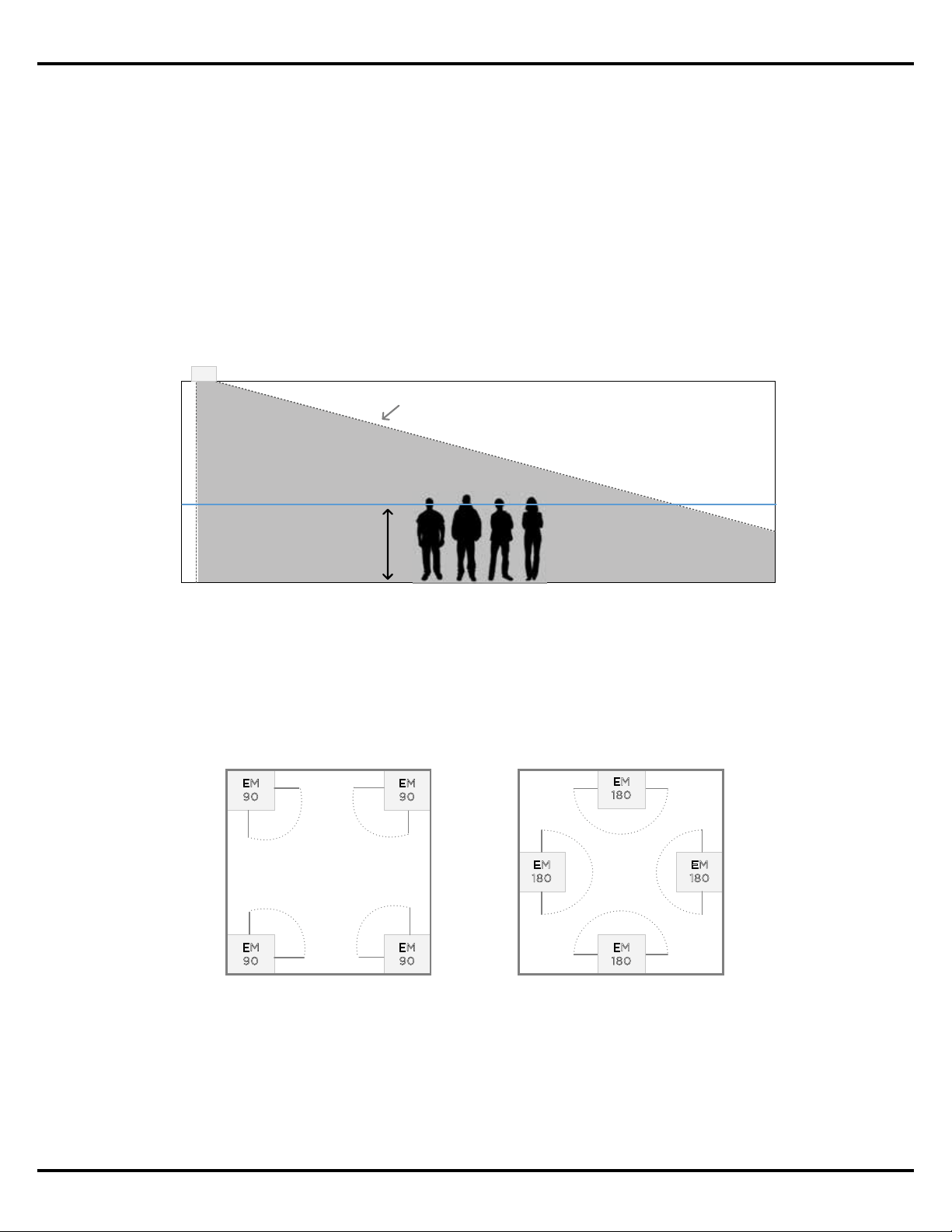
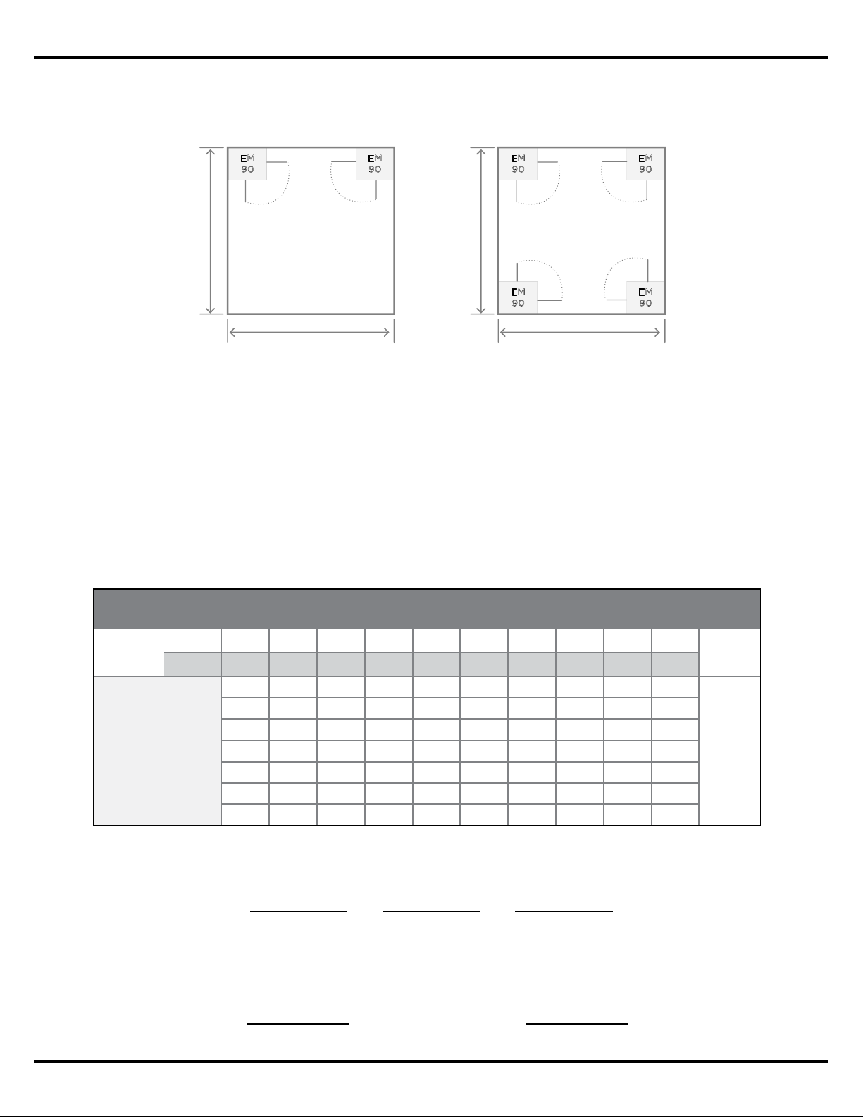
Today, the EdgeMax family includes two horizontal coverage patterns. The EdgeMax EM90
oers 90-degree horizontal coverage and is intended for corner mounting, while the EM180
oers 180-degree horizontal coverage for mounting along the room perimeter.
Since EdgeMax loudspeakers are specifically designed for mounting along corner and wall
locations they benefit from boundary loading to deliver additional low frequency output as
compared to traditional in-ceiling loudspeakers. Similar to surface-mount loudspeakers, the
coverage pattern of EdgeMax will also allow stereo playback for some rooms, when the room
dimensions allow sucient overlap of coverage.
Figure 4. The proprietary Bose PhaseGuide technology delivers controlled high
frequency coverage like a surface‑mount loudspeaker, from an in‑ceiling location.
EdgeMax Loudspeaker Performance
EdgeMax loudspeakers represent the best of both techniques in that they deliver the coverage
of surface-mounted loudspeaker designs, but from a location in the ceiling. These unique
products meet the visual requirements of architects and interior designers, while delivering the
performance benefits of a high quality surface-mounted loudspeaker design.
EdgeMax loudspeakers utilize a two-way system comprised of a compression driver mounted
to a proprietary Bose PhaseGuide structure, and an 8-inch driver mounted in a tuned, ported
enclosure. Uniquely, EdgeMax loudspeakers have an 75-degree asymmetrical vertical coverage
angle and are engineered to be installed in corners or along room perimeters.
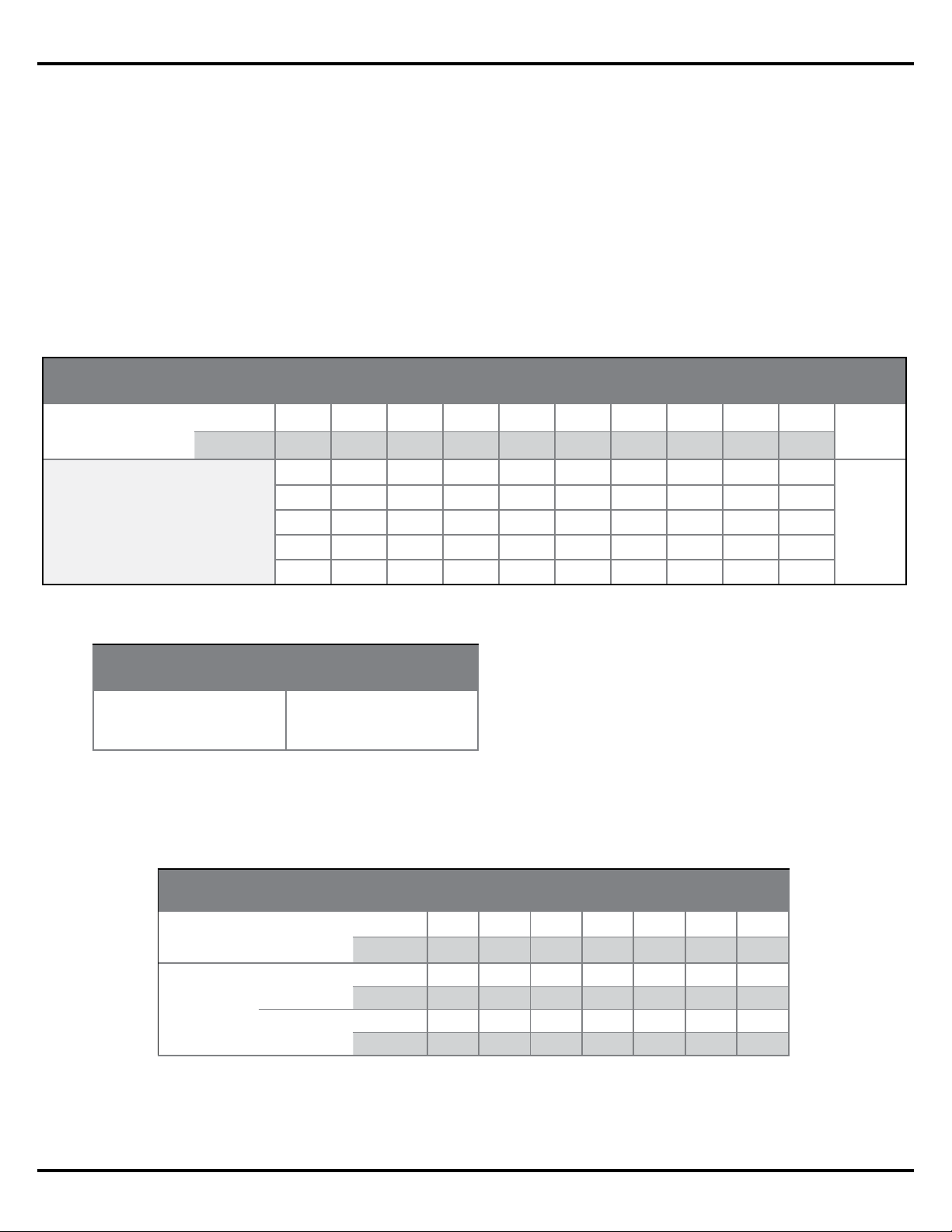
EM90 in Corners
E
M
90
EM
90
EM
9
0
E
M
9
0
EM180 along Walls
E
M
1
8
0
E
M
18
0
EM
1
8
0
EM
18
0
Figure 5. EdgeMax EM90 and EM180 mounting locations.
Application Guide - 6
EdgeMax Design Considerations
EdgeMax Design Considerations
Standard and Premium Coverage
The EdgeMax design guidelines oer two options for quality of coverage: Standard and
Premium. When creating a design with Standard coverage, which should be suitable for most
applications, EdgeMax loudspeakers are spaced such that the overlap between adjacent
loudspeakers occurs at the -10 dB point. A design created with Premium coverage places the
loudspeakers such that they overlap at the -6dB point.
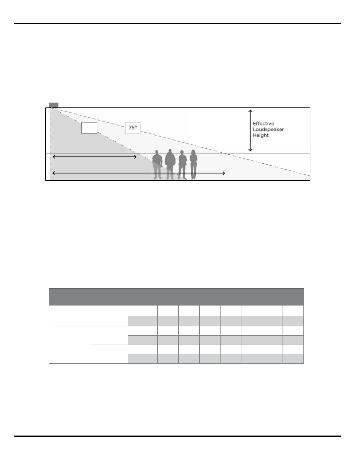
Maximum Room Dimension
Like a surface-mounted loudspeaker, the mounting height of an EdgeMax loudspeaker will
determine its usable throw distance. The usable throw distance is the distance from the
loudspeaker that we can expect to receive balanced frequency response and adequate
loudness for a given application.
The quality of coverage for EdgeMax loudspeakers was derived using the vertical coverage
angle, and confirmed using the Bose® Modeler® software.
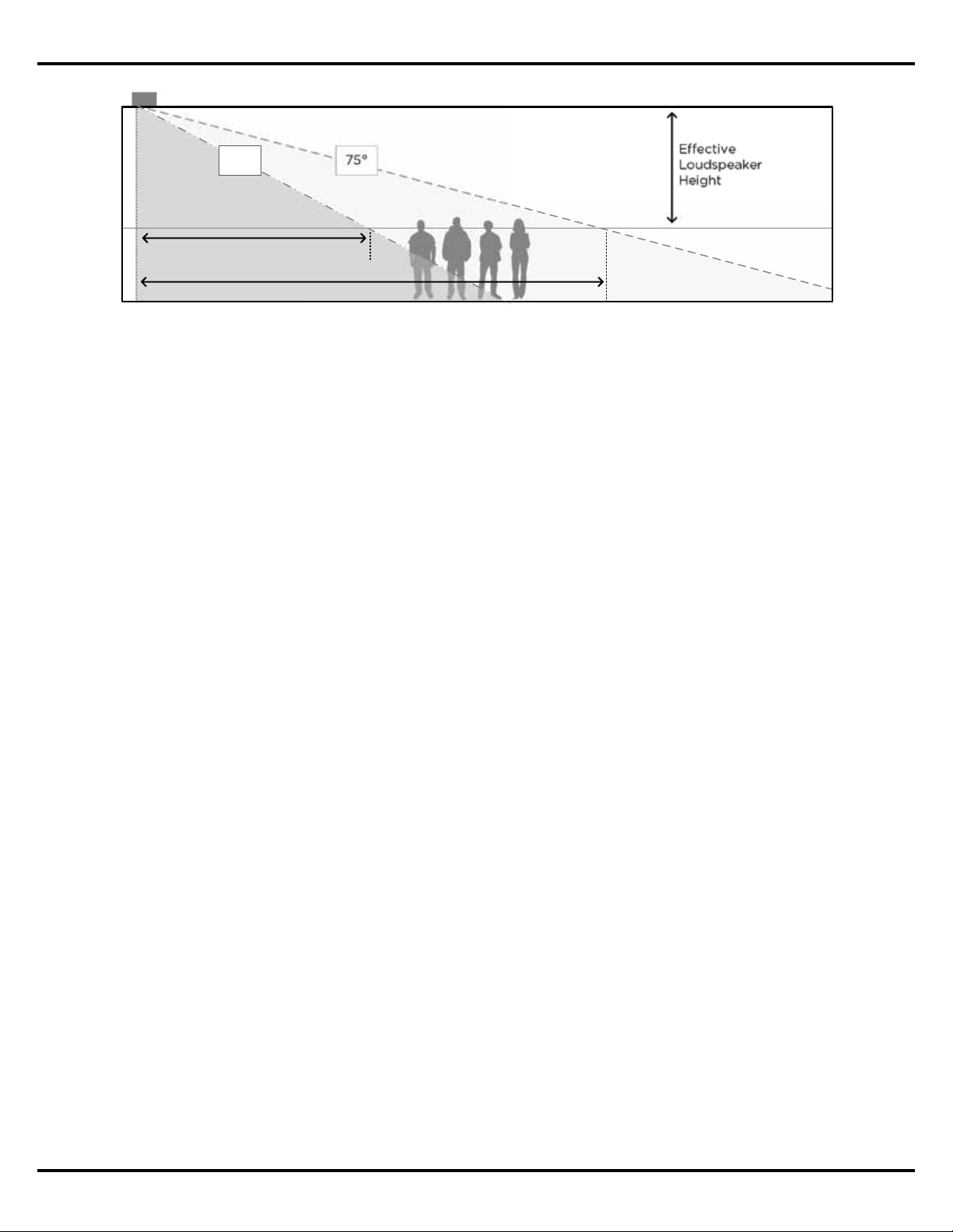
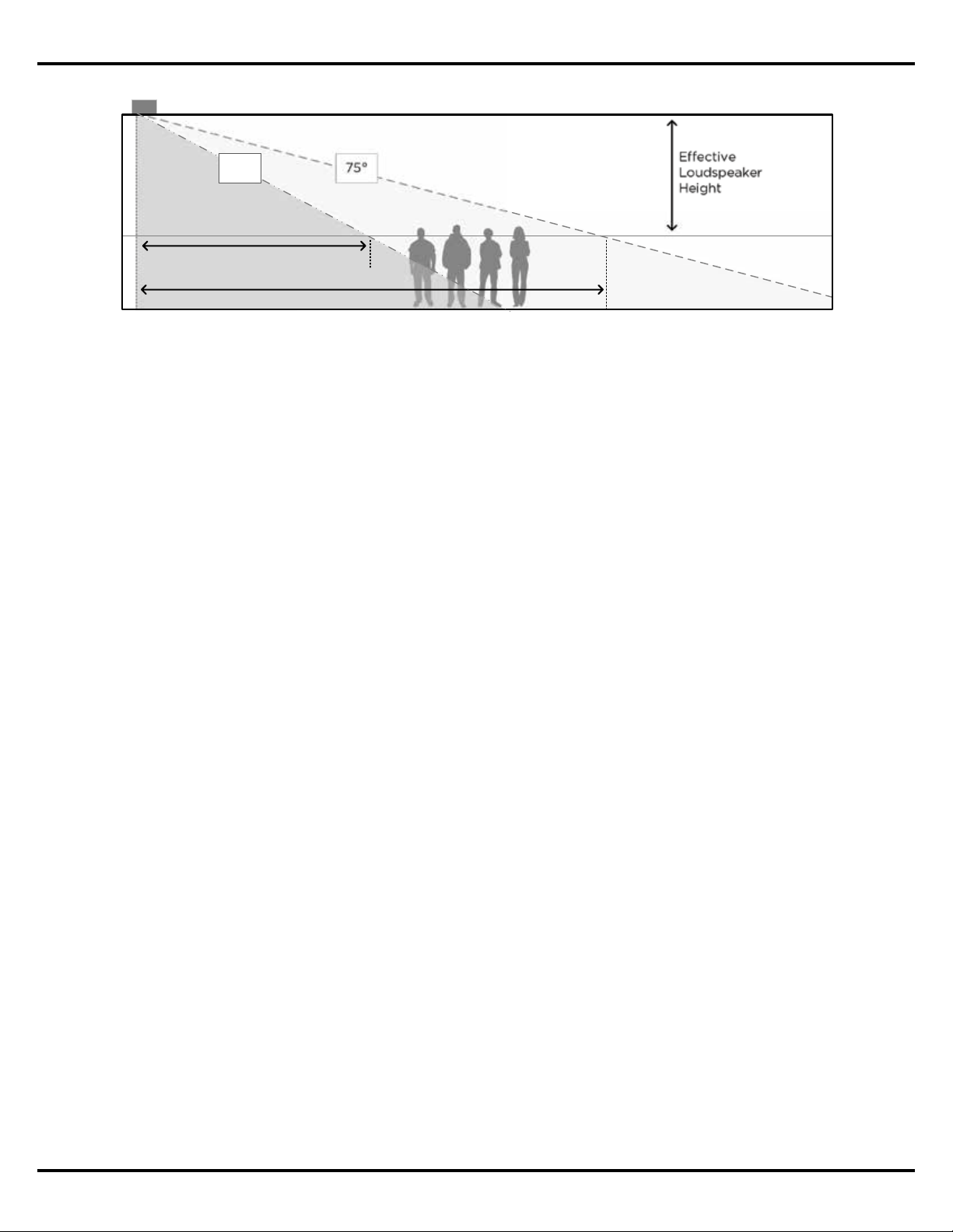
Eective
Loudspeaker
Height
75
°
4.2 m | 14 ft ceiling
1.5 m | 5 ft ear height
Premium Coverage
(nominal -6 dB)
Standard Coverage (nominal -10 dB)
62°
Figure 6. Standard and Premium coverage comparison for EdgeMax loudspeakers.
Figure 7. Usable Throw Distance based on coverage quality for various ceiling heights.
Assumes 1.5 m (5’) ear height.
Usable Throw Distance, EdgeMax EM90 and EM180
Mounting Height
m 2.7 3.0 3.7 4.3 4.9 5.5 6.1
ft 9 10 12 14 16 18 20
Coverage
Quality
Premium
m 2 2 3 4 5 6 7
ft 7 8 11 15 18 21 24
Standard
m 3 4 6 8 9 11 13
ft 11 14 19 25 30 35 40
Application Guide - 7
EdgeMax Design Considerations
The following are two examples of how the Maximum Room Dimension is applied in an
EdgeMax design. The first is when EdgeMax loudspeakers are used along one side of the
coverage area. The second is when they are installed along both sides of the coverage area.
When placing EdgeMax loudspeakers along one side of the coverage area, the Maximum
Room Dimension should be less than or equal to the Usable Throw Distance.
In applications where EdgeMax loudspeakers will be mounted on two opposing sides of the
room, the Maximum Room Dimension is twice the Usable Throw Distance for the planned
ceiling height.
4.2 m | 14 ft ceiling
EM180 Single Wall Mounting
E
M
1
80
Maximum Room Dimension
(8 m | 25 ft)
E
M
1
8
0
Usable
Throw
Distance
Figure 8. The Maximum Room
Dimension is less than or equal
to the Usable Throw Distance
when EdgeMax loudspeakers
are placed along one edge of
the area to be covered.
Figure 9. The Maximum Room
Dimension is equal to twice
the Usable Throw Distance
when EdgeMax loudspeakers
are mounted on two opposing
sides of the area to be covered.
4.2 m | 14 ft ceiling
EM180 Perimeter Mounting
E
M
18
0
Maximum Room Dimension
(16 m | 50 ft)
E
M
1
80
EM
180
EM
180
2x Usable
Throw
Distance
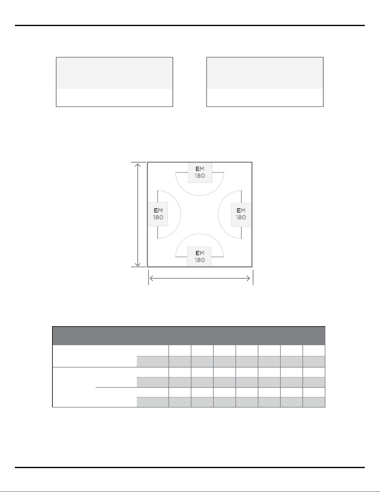
The Maximum Room Dimension is applied to EdgeMax designs to prevent the creation of a
design which lacks sucient coverage in the center of the room – particularly in the case of a
square room where EM90 loudspeakers are used in the corners.
Figure 10. In this example the
Maximum Room Dimension has
been exceeded, resulting in a
coverage gap in the center of
the room.
E
M
9
0
4.2 m | 14 ft ceiling
EM90 Corner Mounting
Exceeds Maximum Room Dimension
> 2 x Usable Throw Distance
E
M
9
0
E
M
9
0
E
M
9
0
Application Guide - 8
EdgeMax Design Considerations
When working with rectangular-shaped coverage areas it is possible to exceed the Maximum
Room Dimension in one dimension, either length or width, but not both. In this case the design
is treated as any other surface-mounted system design by spacing the EdgeMax loudspeakers
along the perimeter using a spacing constant based on the mounting height, and desired
coverage quality.
The spacing constant is the Loudspeaker Spacing Distance. This distance is based on
the vertical coverage angle of the EdgeMax loudspeakers for both premium and standard
coverage types, and is calculated based on the ceiling height where the loudspeakers will be
installed.
Figure 12. Loudspeaker Spacing Distance table for various ceiling heights and coverage quality.
Assumes 1.5 m (5’) ear height.
Maximum Room Dimension
Loudspeaker Spacing Distance
0.5 x
Loudspeaker
Spacing
E
M
1
8
0
EM
180
E
M
1
8
0
E
M
1
8
0
Variable Room Dimension
Figure 11. The room size can
exceed the Maximum Room
Dimension in one dimension,
length or width, to create a
distributed design along the
perimeter of the room.
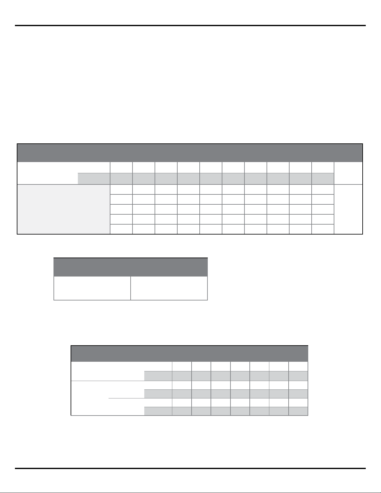
Balancing SPL In Mixed EM90 and EM180 Systems
EdgeMax loudspeakers are available in two horizontal coverage models, 90 and 180-degree
(EM90 and EM180, respectfully). The dierence in horizontal coverage results in a 3 dB
sensitivity dierence between the two devices, with the EM180 being 3 dB less sensitive than
the EM90 model.
When designing a system that will mix both EdgeMax EM90 and EM180 loudspeakers, you will
need to set the power level to the EM90 loudspeakers 3 dB less than the EM180 loudspeakers
to achieve equivalent loudness. In 70/100V constant voltage applications, this can be easily
achieved by setting your EM90 loudspeakers one tap setting lower then the EM180s in the
same room.
Loudspeaker Spacing Distance, EdgeMax EM180
Mounting Height
m 2.7 3.0 3.7 4.3 4.9 5.5 6.1
ft 9 10 12 14 16 18 20
Coverage
Quality
Premium
m 3 4 6 8 9 11 13
ft 11 15 20 25 30 35 40
Standard
m 7 9 12 12 12 12 12
ft 20 30 40 40 40 40 40
Application Guide - 9
EdgeMax Design Considerations
EdgeMax Active Equalization
EdgeMax loudspeakers have an active equalization curve to deliver optimum performance
when installed. Each EdgeMax loudspeaker model has a specific equalization curve that is
available to apply via Bose ControlSpace® sound processors and PowerMatch® amplifiers
using ControlSpace Designer™ software, or PowerShare amplifiers using PowerShare Editor
software.
The following guidelines should be applied when choosing the correct equalization curve for
your application:
EdgeMax EM90 loudspeaker EQ – Use when the system contains only EM90
loudspeakers, or when a mixed line EM180 and EM90 system will be installed.
EdgeMax EM180 loudspeaker EQ – Use when the system contains only EM180
loudspeakers.

Application Guide - 10
Design Worksheet, EdgeMax EM180 & Mixed EM90/EM180 Systems
Design Worksheet
EdgeMax EM180 & Mixed EM90/EM180 Systems
This design worksheet covers the basic steps for the creation of a system design comprised of
EdgeMax EM180 in commercial audio/business music systems. EdgeMax EM180 loudspeakers
are ideally suited for background/foreground music applications with mounting heights
between 2.4 to 6.1 m (8 to 20’).
EdgeMax loudspeakers utilize a two-way design comprised of a compression driver mounted
in a proprietary PhaseGuide to deliver asymmetrical high frequency coverage, and an
8-inch driver mounted in a tuned, ported enclosure. EdgeMax loudspeakers are compatible
with 70/100V and low-impedance amplifiers, and can deliver up to 98 dBSPL in a typical
application with a 4.9m (16’) ceiling height.
The design process described within this document uses three key requirements for the
creation of the design, these are:
1. Loudness: What sound pressure level is required for this application?
2. Coverage: How consistent must the sound be across the entire coverage area?
3. Response: What bandwidth is required for the type of program material that will be used?
Each of these requirements can be easily converted into a specification that we can use
to create our system design. If we understand the customer’s needs in these three areas,
we can deliver a design that will, at a minimum, meet their needs, and at best, exceed their
expectations. For the purposes of this design guide, we will assume that you are familiar with
the system requirements for typical business music systems and are ready to focus on the
creation of a speaker layout using EdgeMax loudspeakers.
Design Guidelines
EdgeMax loudspeakers provide asymmetrical vertical coverage, and either 90 or 180-degree
horizontal coverage. The design guidelines presented here oer two coverage quality options
– Premium and Standard.
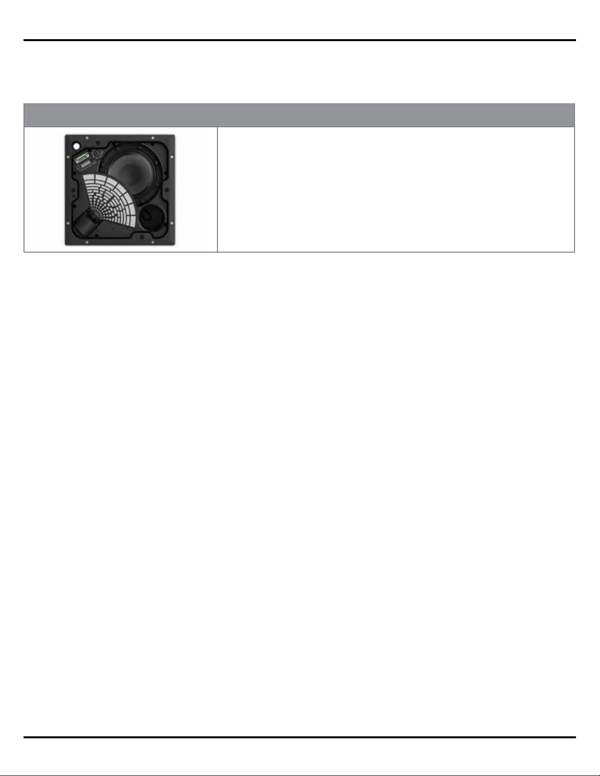
EM180
Product Specifications
Frequency Range: 50 Hz – 18 kHz ± 3 dB
Long Term Power Handling: 125 watts continuous
Sensitivity: 93 dBSPL @ 1 W/1 m (pink noise)
Impedance: 70/100V or 8
Maximum Acoustic Output: 114 dB-SPL @ 1 m (pink noise)
Dispersion: 180° x 75° (H x V)
Application Guide - 11
Design Worksheet, EdgeMax EM180 & Mixed EM90/EM180 Systems
When creating a design that uses the EdgeMax loudspeakers you should consider the
following:
• Recommended mounting height for EdgeMax loudspeakers is between 2.7 and 6.1 m
(9 and 20’)
• Maximum SPL for a typical application is between 95 and 110 dBSPL
• Always add 25% headroom to your amplifier to accommodate various types of program
material.
Eective
Loudspeaker
Height
75
°
4.2 m | 14 ft ceiling
1.5 m | 5 ft ear height
Premium Coverage
(nominal -6 dB)
Standard Coverage (nominal -10 dB)
62°
Application Guide - 12
Design Worksheet, EdgeMax EM180 & Mixed EM90/EM180 Systems
Design Worksheet
Use the following worksheet to create a design using EdgeMax loudspeakers.
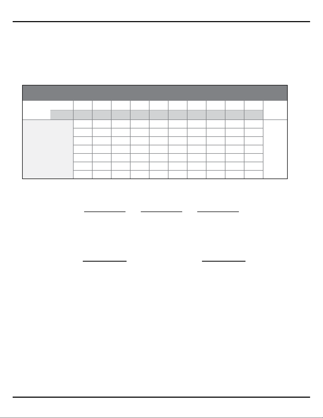
Step 1: Confirm that the EdgeMax loudspeaker will meet your loudness requirement.
A. On the chart below, locate the loudspeaker mounting height for this design.
B. Draw a line down to the desired maximum SPL.
C. Draw a horizontal line across the chart at your desired SPL level.
D. Loudspeakers listed below the line will meet your loudness requirement.
Step 2: Confirm that the EdgeMax loudspeaker will meet your response requirement.
Step 3: Using the graph paper on the last page, create a sketch or drawing of the room.
Step 4: Using the chart below, determine the Usable Throw Distance for the loudspeaker
mounting height that will be used with your design.
NOTE: EdgeMax loudspeakers have a usable
Frequency Response down to 50 Hz, so additional
subwoofers may not be required. However, if
designers find a need for additional bass, the MB210
compact subwoofer can be used.
Full Range Extended Range
FreeSpace DS 16
FreeSpace DS 40
FreeSpace DS 100
EdgeMax EM90/EM180
FreeSpace 3 System
1.) Locate the mounting height you will be using for the design.
2.) Determine the usable throw distance for the desired coverage requirement.
NOTE: For rectangular rooms, one dimension, (length or width), cannot exceed
the maximum.
Maximum Continuous Output Level
Loudspeaker
Mounting Height
m 2.4 3.0 3.7 4.3 4.9 5.5 6.1 6.7 7.9 9.8
ft 8 10 12 14 16 18 20 22 26 32
DS 16F 99 96 93 91 89 88 87 86 84 82
dB
SPL
DS 40F 106 103 100 98 96 95 94 93 91 89
DS 100F 108 107 104 102 100 99 98 97 95 93
EM90 111 109 106 104 102 100 99 98 96 95
EM180 108 106 103 101 99 97 96 95 93 92
Usable Throw Distance, EdgeMax EM90 & EM180
Mounting Height
m 2.7 3.0 3.7 4.3 4.9 5.5 6.1
ft 9 10 12 14 16 18 20
Coverage
Quality
Premium
m 2 2 3 4 5 6 7
ft 7 8 11 15 18 21 24
Standard
m 3 4 6 8 9 11 13
ft 11 14 19 25 30 35 40
Application Guide - 13
Design Worksheet, EdgeMax EM180 & Mixed EM90/EM180 Systems
Step 5: Select the type of layout that will be used for your room’s shape. Proceed to the
design step noted.
Step 6 (Square): Place the EdgeMax loudspeakers in corners or centered along walls. Proceed
to step 8 when complete.
Step 7 (Rectangle): Determine the Loudspeaker Spacing Distance for the mounting height
and desired coverage quality.
Square Shaped
Room / Coverage Area
Rectangular Shaped
Room / Coverage Area
petS ot deecorP petS ot deecorP
67
EM180 Square Room
2x Usable Throw Distance
2x Usable Throw Distance
EM
180
EM
180
EM
180
EM
180
Loudspeaker Spacing Distance, EdgeMax EM180
Mounting Height
m 2.7 3.0 3.7 4.3 4.9 5.5 6.1
ft 9 10 12 14 16 18 20
Coverage
Quality
Premium
m 3 4 6 8 9 11 13
ft 11 15 20 25 30 35 40
Standard
m 7 9 12 12 12 12 12
ft 20 30 40 40 40 40 40
Application Guide - 14
Design Worksheet, EdgeMax EM180 & Mixed EM90/EM180 Systems
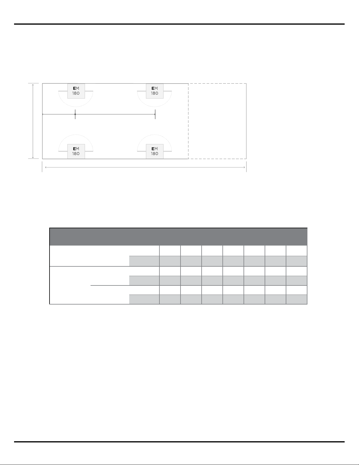
Loudspeaker Spacing Distance
0.5 x
Loudspeaker
Spacing
EM180 Single Edge Mounting
Variable Room Dimension
Usable Throw
Distance
EM
180
EM
180
Create a layout using one of the three layout options below.
Single Edge Mounting – place the EdgeMax loudspeakers along a side wall using the
spacing distance for the mounting height that will be used.
Proceed to step 6.
Perimeter Mounting – place the EdgeMax loudspeakers along side walls using the spacing
distance for the mounting height that will be used.
Mixed (Recommended) – place the EdgeMax loudspeakers along side walls using the
spacing distance for the mounting height that will be used. Follow the guidelines for
Single Edge and Perimeter mountings.
EM
180
EM
180
Loudspeaker Spacing Distance
0.5 x
Loudspeaker
Spacing
EM180 Perimeter Mounting
Variable Room Dimension
2x Usable Throw Distance
EM
180
EM
180
EM90 & EM180 Mixed Mounting
Variable Room Dimension
Up to 2x Usable Throw
Distance
EM
180
EM
90
Loudspeaker Spacing Distance
EM
180
EM
90
Application Guide - 15
Design Worksheet, EdgeMax EM180 & Mixed EM90/EM180 Systems
Step 8 (Amplifier Size): Calculate the required amplifier size. Use the Tap Chart below to
determine which loudspeaker tap is required for this design.
A. Locate the loudspeaker mounting height for this design.
B. Draw a line down to the desired maximum SPL.
C. Draw a horizontal line across the chart to read the required loudspeaker tap.
D. Calculate the required amplifier power:
E. Calculate the required amplifier size:
NOTE: When working with a mixed EM90 and EM180 system, the EM90 loudspeakers should
be tapped 3 dB less than the EM180 loudspeakers to balance the overall SPL level.
Continuous SPL Chart, EM180 & Mixed
Mount
Height
m 2.7 3.0 3.7 4.3 4.9 5.5 6.1 6.7 7.9 9.1
ft 9 10 12 14 16 18 20 22 26 30
TAP
2.5 91 89 86 84 82 80 79 78 76
dB
SPL
5 94 92 89 87 85 83 82 81 79 78
10 97 95 92 90 88 86 85 84 82 81
20 100 98 95 93 91 90 88 87 85 84
40 103 101 98 96 94 93 91 90 88 87
80 106 104 101 99 97 96 94 93 91 90
8 Ohm 108 106 103 101 99 97 96 95 93 92
Number of
Loudspeakers
Required
Loudspeaker Tap
Power
Required
X
=
Power Required
Headroom Amplifier Size
X
=
1.25
Application Guide - 16
Design Worksheet, EdgeMax EM90 Systems
Design Worksheet
EdgeMax EM90 Systems
This design worksheet covers the basic steps for the creation of a system design comprised of
EdgeMax EM90 in commercial audio/ business music systems. EdgeMax EM90 loudspeakers
are ideally suited for background/foreground music applications with mounting heights
between 2.4 to 6.1 m (8 and 20’).
EdgeMax loudspeakers utilize a two-way design comprised of a compression driver mounted
in a proprietary PhaseGuide to deliver asymmetrical high frequency coverage, and an
8-inch driver mounted in a tuned, ported enclosure. EdgeMax loudspeakers are compatible
with 70/100V and low-impedance amplifiers, and can deliver up to 98 dBSPL in a typical
application with a 4.9 m (16’)ceiling height.
The design process described within this document uses three key requirements for the
creation of the design, these are:
1. Loudness: What sound pressure level is required for this application?
2. Coverage: How consistent must the sound be across the entire coverage area?
3. Response: What bandwidth is required for the type of program material that will be used?
Each of these requirements can be easily converted into a specification that we can use
to create our system design. If we understand the customer’s needs in these three areas,
we can deliver a design that will, at a minimum, meet their needs, and at best, exceed their
expectations. For the purposes of this design guide, we will assume that you are familiar with
the system requirements for a business music system and are ready to focus on the creation of
a speaker layout using EdgeMax loudspeakers.
Design Guidelines
EdgeMax loudspeakers provide an asymmetrical vertical coverage, and either 90 or
180-degree horizontal coverage. The design guidelines presented here oer two coverage
quality options – Premium and Standard.
EM90
Product Specifications
Frequency Range: 50 Hz – 18 kHz ± 3 dB
Long Term Power Handling: 125 watts continuous
Sensitivity: 96 dBSPL @ 1 W/1 m (pink noise)
Impedance: 70/100V or 8
Maximum Acoustic Output: 117 dB-SPL @ 1 m (pink noise)
Dispersion: 90° x 75° (H x V)
Application Guide - 17
Design Worksheet, EdgeMax EM90 Systems
When creating a design that uses the EdgeMax loudspeakers you should consider the
following:
• Recommended mounting height for EdgeMax loudspeakers is between 2.7 and 6.1 m
(9 and 20’)
• Maximum SPL for a typical application is between 95 and 110 dBSPL
• Always add 25% headroom to your amplifier to accommodate various types of program
material.
Eective
Loudspeaker
Height
75
°
4.2 m | 14 ft ceiling
1.5 m | 5 ft ear height
Premium Coverage
(nominal -6 dB)
Standard Coverage (nominal -10 dB)
62°
Application Guide - 18
Design Worksheet, EdgeMax EM90 Systems
Design Worksheet
Use the following worksheet to create a design using EdgeMax loudspeakers.
Step 1: Confirm that the EdgeMax loudspeaker will meet your loudness requirement.
A. On the chart below, locate the loudspeaker mounting height for this design.
B. Draw a line down to the desired maximum SPL.
C. Draw a horizontal line across the chart at your desired SPL level.
D. Loudspeakers listed below the line will meet your loudness requirement.
Step 2: Confirm that the EdgeMax loudspeaker will meet your Response Requirement.
Step 3: Using the graph paper on the last page, create a sketch or drawing of the room.
Step 4: Using the chart below, determine the Usable Throw Distance for the loudspeaker
mounting height that will be used with your design.
NOTE: EdgeMax loudspeakers have a usable
Frequency Response down to 45 Hz, so additional
subwoofers may not be required. However, if
designers find a need for additional bass, the MB210
compact subwoofer can be used.
Full Range Extended Range
FreeSpace DS 16
FreeSpace DS 40
FreeSpace DS 100
EdgeMax EM90/EM180
FreeSpace 3 System
1.) Locate the mounting height you will be using for the design.
2.) Determine the usable throw distance for the desired coverage
requirement.
Maximum Continuous Output Level
Loudspeaker
Mounting Height
m 2.4 3.0 3.7 4.3 4.9 5.5 6.1 6.7 7.9 9.8
ft 8 10 12 14 16 18 20 22 26 32
DS 16F 99 96 93 91 89 88 87 86 84 82
dB
SPL
DS 40F 106 103 100 98 96 95 94 93 91 89
DS 100F 108 107 104 102 100 99 98 97 95 93
EM90 111 109 106 104 102 100 99 98 96 95
EM180 108 106 103 101 99 97 96 95 93 92
Usable Throw Distance, EdgeMax EM90 and EM180
Mounting Height
m 2.7 3.0 3.7 4.3 4.9 5.5 6.1
ft 9 10 12 14 16 18 20
Coverage
Quality
Premium
m 2 2 3 4 5 6 7
ft 7 8 11 15 18 21 24
Standard
m 3 4 6 8 9 11 13
ft 11 14 19 25 30 35 40
Application Guide - 19
Design Worksheet, EdgeMax EM90 Systems
Step 5: Select the type of layout that will be used based on the Usable Throw Distance, and
the dimensions of the room where the system will be installed.
Step 6 (Amplifier Size): Calculate the required amplifier size. Use the Tap Chart below to
determine which loudspeaker tap is required for this design.
A. Locate the loudspeaker mounting height for this design.
B. Draw a line down to the desired maximum SPL.
C. Draw a horizontal line across the chart to read the required loudspeaker tap.
D. Calculate the required amplifier power:
E. Calculate the required amplifier size:
4x EM90 in Corners
EM
90
EM
90
EM
90
EM
90
2x Usable Throw Distance
2x Usable Throw Distance
2x EM90 in Corners
EM
90
EM
90
Usable Throw Distance
Usable Throw Distance
Number of
Loudspeakers
Required
Loudspeaker Tap
Power
Required
X
=
Power Required
Headroom Amplifier Size
X
=
1.25
Continuous SPL, EdgeMax EM90
Mount
Height
m 2.7 3.0 3.7 4.3 4.9 5.5 6.1 6.7 7.9 9.1
ft 9 10 12 14 16 18 20 22 26 30
TAP
2.5 94 92 89 87 85 83 82 81 79 78
dB
SPL
5 97 95 92 90 88 86 85 84 82 81
10 100 98 95 93 91 89 88 87 85 84
20 103 101 98 96 94 93 91 90 88 87
40 106 104 101 99 97 96 94 93 91 90
80 109 107 104 102 100 99 97 96 94 93
8 Ohm 111 109 106 104 102 100 99 98 96 95
NOTE: For designs where bass is a primary consideration, square rooms
with 4x EM90s will deliver more bass then 4x EM180s, due to the additional
wall‑boundary loading provided by the corner mounting.
Application Guide - 20
Sample EdgeMax Conference Room Appplications
Sample EdgeMax Conference Room Applications
The unique coverage performance of EdgeMax loudspeakers makes them ideal solution in
conference room applications, for both speech and music reproduction. Mounting an EM180
directly above a video screen provides excellent speech reproduction and localization for
video conferencing applications, while the addition of EM180 loudspeakers along the side
walls of larger rooms enhances both video and audio conferencing.
Small Conference Rooms
For smaller conference rooms with dimensions less than 3 x 4.5 m (10 x 15’), with a ceiling
height of 2.7 – 3.7 m (9 - 12’), a single EM180 is sucient above the main video screen location
for both audio and video conferencing. If stereo playback of program material is desired two
EM90s can be installed in the two corners to the left and right of the video screen location.
Note that stereo playback can also be used in other applications, including background and
foreground music, when room dimensions allow similar overlap.
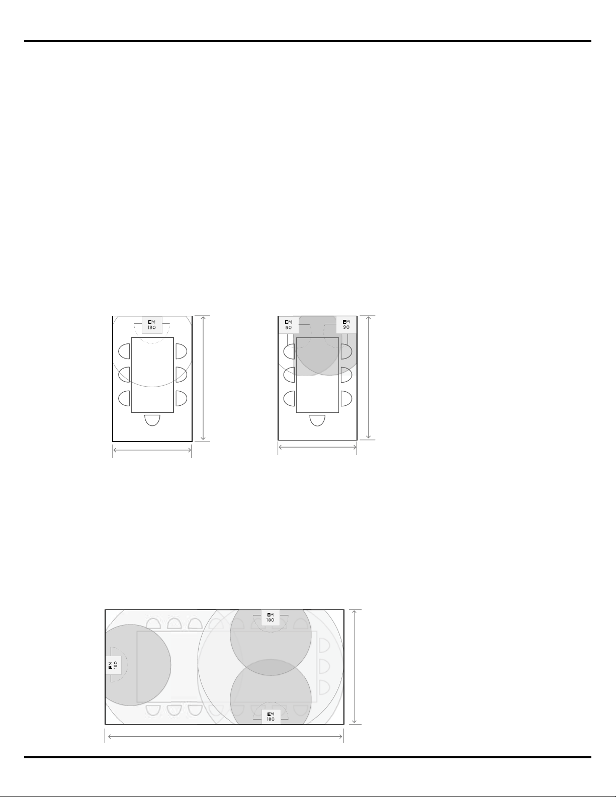
Medium Conference Rooms
For medium and large-sized conference rooms with dimensions greater than 3 x 4.5 m (10
x 15’), with a ceiling height of 2.7 – 3.7 m (9 - 12’), a single EM180 can be used above the
main video screen location for both audio and video conferencing, and additional EM180s
are placed behind the conferencing table using the recommended loudspeaker spacing
dimensions for a room’s ceiling height.
Small Conference Room
EM180 Mounted Above Screen
3.0 m | 10 ft ceiling
(4.6 m | 15 ft)
(3 m | 10 ft)
Small Conference Room
EM90s Mounted In Corners
3.0 m | 10 ft ceiling
(4.6 m | 15 ft)
(3 m | 10 ft)
EM
9
0
E
M
9
0
EM
1
8
0
Figure 13. In smaller
conference rooms a single
EM180 can be used above the
screen location, or two EM90s
in the corners can provide both
speech and program material
reinforcement.
Medium Conference Room
EM180 Mounted Along Perimeter
3.0 m | 10 ft ceiling
(7.6 m | 25 ft)
(4.5 m | 15 ft)
EM
180
EM
18
0
EM
18
0
Figure 14. In medium sized
conference rooms a single
EM180 is used above the screen
location, and additional EM180s
along the edges provide
reinforcement for audio and
video conferencing.
Application Guide - 21
Sample EdgeMax Conference Room Applications
In video conferencing applications where additional EdgeMax loudspeakers are utilized to
cover the conference room, they should be reduced in level relative to the loudspeaker above
the screen to provide adequate localization.
If stereo playback of program material is desired, two EM90s can be installed in the two
corners to the left and right of the video screen location.
Large Conference Rooms
For large (or divisible) conference rooms, similar guidelines are recommended. Place
EdgeMax loudspeakers near the main video screen to provide adequate localization for video
conferencing or playback, and other EdgeMax loudspeakers along the perimeter of the room
using the spacing guidelines for the room’s ceiling height and desired coverage quality.
Figure 15. In medium‑sized
conference rooms two EM90s
can be mounted in the front of
the room for stereo playback
and conferencing, while
additional EM180s can be
installed along the side walls for
conferencing reinforcement.
EM
9
0
Medium Conference Room
EM90 and EM180s Mounted Along Perimeter
3.0 m | 10 ft ceiling
(7.6 m | 25 ft)
(4.5 m | 15 ft)
EM
1
8
0
E
M
18
0
EM
90
Figure 16. A large conference
room with two EM180s
mounted near the video screen
location, and additional units
spaced along room sides using
the recommended loudspeaker
spacing for the room’s ceiling
height.
(10.6 m | 35 ft)
EM
180
EM
180
E
M
1
8
0
EM
1
8
0
EM
18
0
EM
18
0
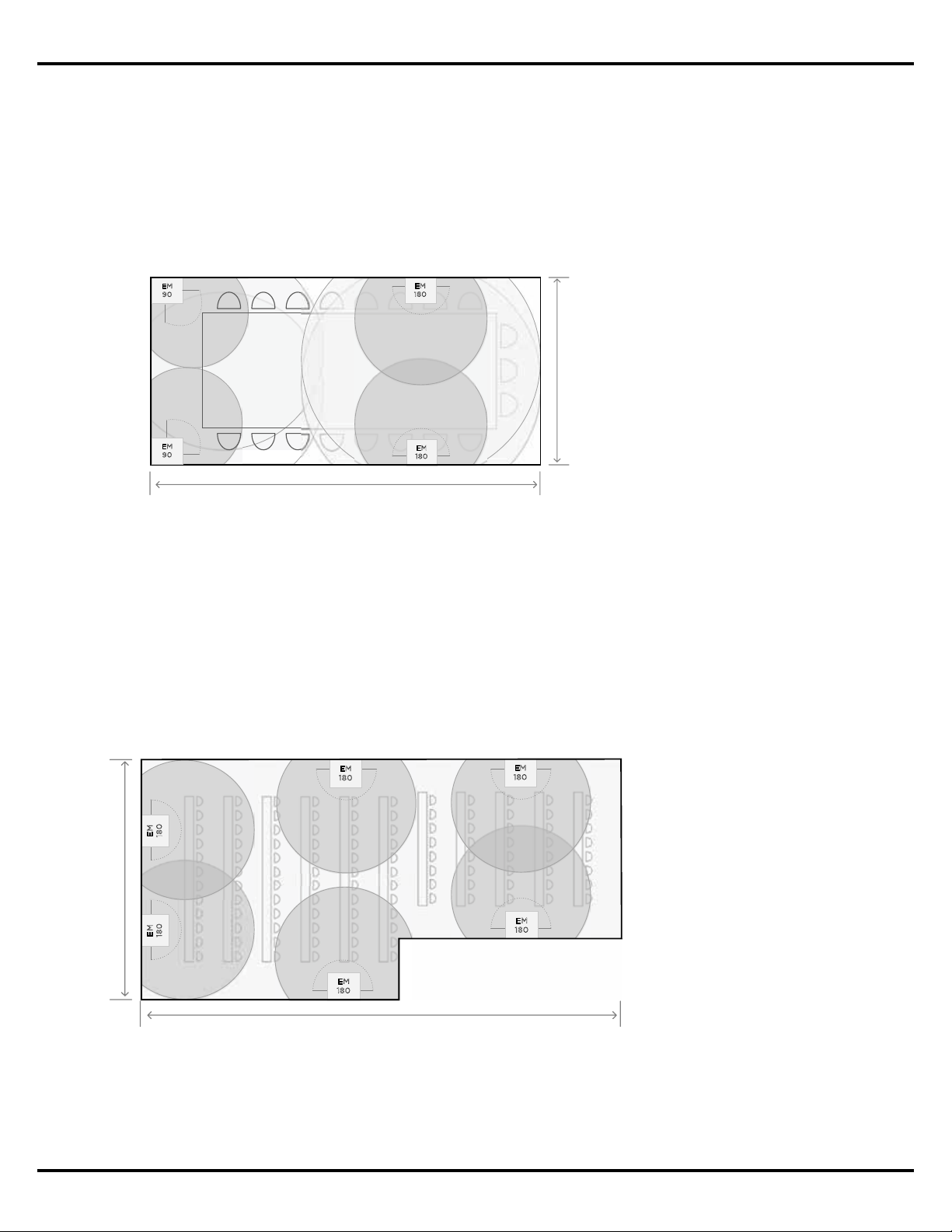
(21 m | 70 ft)
Large Conference Room
EM180s Mounted Along Perimeter
4.3 m | 14 ft ceiling
PROFESSIONAL
©2017 Bose Corporation, All rights reserved.
Framingham, MA 01701-9168 USA
PRO.BOSE.COM
All trademarks are the property of their respective owners
v1, November 2017
10
11 12
13
14
15 16
1
1
2
3
4
5
6
7
8
9
10
11
12
13
14
15
16
17
18
19
20
2
3
4
5 6
7
8
9
0