Loading ...
Loading ...
Loading ...
9
INSTALLATION OF YOUR ICEMAKER
• THIS ICEMAKER SHOULD BE PROPERLY INSTALLED BY A QUALIFIED PROFESSIONAL
This icemaker MUST be installed with electrical and water connections in accordance with
all state and local codes.
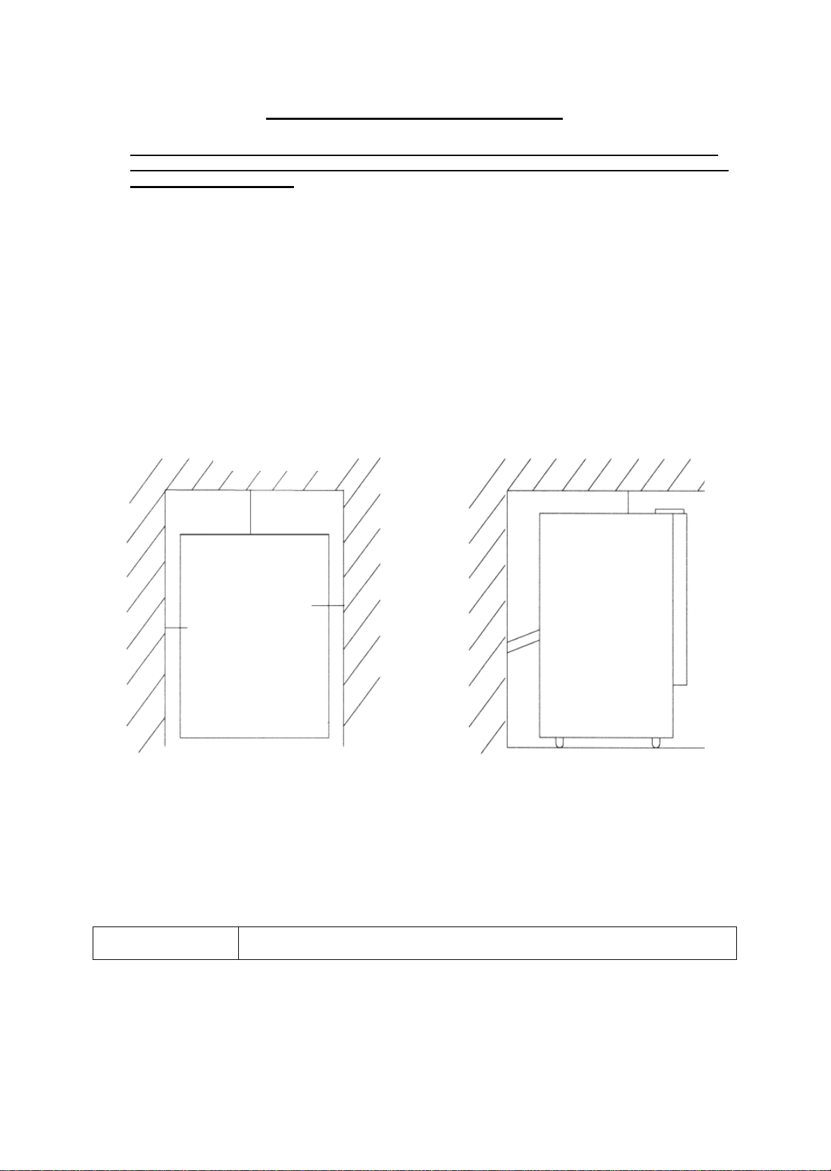
• Allow a minimum of 1 inch of space between the top and sides of the icemaker and a
minimum of 4 inches at the back, which allows the proper air circulation to cool the
compressor. Ensure the front of the unit is completely unobstructed.
• Place your icemaker on a floor that is strong enough to support the icemaker when it is fully
loaded. To level your icemaker, adjust the legs at the front of the icemaker.
• Locate the icemaker away from direct sunlight and sources of heat (stove, heater, radiator, etc.).
Direct sunlight may affect the acrylic coating and heat sources may increase electrical
consumption. Extreme cold ambient temperatures may also cause the icemaker not to perform
properly.
• Choose a well ventilated area with temperatures above 50ºF (10ºC) and below 100ºF (38ºC).
This unit MUST be installed in an area protected from the elements.
• Avoid locating the icemaker in moist areas. Too much moisture in the air will cause frost to form
quickly on the evaporator requiring more frequent defrosting of the icemaker.
INSTALLATION CLEARANCES:
• The installation of this icemaker requires a cold water supply inlet of ¼” (6.35mm) soft copper tubing
with a shut off valve.
• The icemaker requires a continuous water supply with a minimum pressure of 15 psig and a static
pressure not to exceed 80 psig. The temperature of the water supply into the icemaker should be
between 41ºF (5ºC) and 90ºF (32ºC) for proper operation.
• It is strongly recommended that a water filter be used. A filter, if it is of the proper type, can remove
taste and odors as well as particles. Some water is very hard, and softened water may result in
white, mushy cubes that stick together. De-Ionized water is NOT recommended.
Warning
Operation of the icemaker for extended periods outside of the normal
temperature ranges as described above may affect product performance.
SIDE VIEW
TOP VIEW
Top of unit
Rear of unit
Front of unit
Side Side
4”
1”
1”
1”
Loading ...
Loading ...
Loading ...