Loading ...
Loading ...
380260-en-EU_V2.5 8/14
3
Operation
Connecting Test Leads
For all measurements, connect the red test lead to the V input terminal and the black test lead to
the COM input terminal.
Test Lead Check
1. Set the rotary switch to the 200range.
2. Touch the test lead tips together.
3. Resistance should read less than 0.5 and the audio tone should sound.
4. With the leads not touching, the display should read infinity indicated by “1”.
5. Readings displayed other than the readings described above are indicative of a test lead
problem. The test leads must be replaced before using the meter. Failure to do so could result
in damage to equipment and electrical shock.
Insulation Resistance Measurements (Megohmmeter Tests)
Warning: Do not perform Insulation Resistance measurements if AC Voltage is present on the device
under test.
1. Connect the red test lead to the V input terminal; black lead to the COM terminal.
2. Set the function switch to the desired Mtest voltage position.
3. Connect the tips of the test leads to the equipment under test. If there is a voltage present, a
constant beep will sound and the voltage will be displayed.
4. The display will show “1“until the TEST button is pushed. Press and hold the TEST button. The
upper right display shows the test voltage applied and the flashing high voltage symbol
will
be displayed. The main display shows the resistance.
5. Keep the test leads connected to the equipment under test and release the TEST button. The
circuit will discharge through the meter. Keep the test leads connected until the circuit is
completely discharged and the upper right display shows 0 volts.
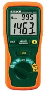
Lock Function
For hands-free operation, use the LOCK feature.
1. With the test leads connected to the equipment under test, simultaneously press the TEST and
LOCK keys.
2. The LOCK icon”
” will appear on the display. A beeper will sound every 2 seconds to
indicate that the meter is in Lock mode.
3. Press the LOCK key to disable the Lock function and end the test.
Warning
Ensure that the circuit under test does not include components that can be damaged by 1000VDC; such
devices include power factor correction capacitors, low voltage mineral insulated cables, electronic light
dimmers, and ballasts/starters for fluorescent lamps.
Loading ...
Loading ...
Loading ...