
OPERATING
INSTRUCTION MANUAL
08/54578/0 ISSUE 1 OCN -----
EN: This product is only suitable for well insulated rooms or occasional use. DE: Dieses Produkt ist nur für gut isolierte Bereiche oder
gelegentliche Verwendung geeignet. FR: Ce produit convient uniquement à des endroits bien isolés ou pour un usage occasionnel.
IT: Questo prodotto è adatto solo per spazi ben isolati o per uso occasionale. ES: Este producto sólo es adecuado para espacios
bien aislados o un uso ocasional. NL: Dit product is uitsluitend geschikt voor goed geïsoleerde ruimten of voor sporadisch gebruik.
PL: Produkt ten jest odpowiedni wyłącznie do dobrze odizolowanych miejsc lub do okazjonalnego użytku. NO: Dette produktet egner
seg kun for godt isolerte rom eller sporadisk bruk. RO: Acest produs este adecvat exclusiv spaţiilor bine ventilate sau utilizării ocazionale.
CZ: Tento výrobek je vhodný pouze do dobře izolovaných prostor nebo k příležitostnému použití. DK: Dette produkt er kun egnet til
velisolerede rum eller lejlighedsvis brug. PT: Este produto somente é adequado para espaços bem isolados ou uso ocasional. SE: Denna
produkt är endast avsedd för välisolerade utrymmen eller tillfällig användning. FI: Tämä tuote soveltuu ainoastaan hyvin eristettyihin tiloihin
tai satunnaiseen käyttöön. SK: Tento výrobok je vhodný len pre dobre izolované priestory alebo na občasné použitie. SI: Ta izdelek je
primeren le za dobro izolirane prostore ali za občasno uporabo. HR: Ovaj proizvod je pogodan samo za dobro izolirane prostore ili
povremenu upotrebu. HU: Ez a termék csak jól szigetelt terekhez vagy eseti használatra alkalmas
The product complies with the European Safety Standards and the European Standard Electromagnetic Compatibility (EMC)
These cover the essential requirements of EEC Directives
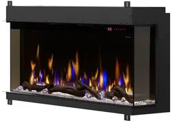
Vivente Landscape Electric Fire
Models: VVT75, VVT100, VVT150

2
CAUTION: Please read this information guide carefully to be able to safely install,
use and maintain your product.
Important Safety Advice
When using electrical appliances, basic precautions should always be followed to reduce
the risk of fire, electrical shock and injury to persons, including the following:
If the appliance is damaged, check with the supplier before installation and operation.
• Do not use outdoors.
• Do not use in the immediate surroundings of a bath, shower or swimming pool.
• Do not locate the appliance immediately below a fixed socket outlet or connection box.
• Do not use this heater if it has been dropped.
• Do not use if there are visibe signs of damage to the heater.
• Use this heater on a horizontal and stable surface.
Children of less than 3 years should be kept away unless continuously supervised.
Children aged from 3 years and less than 8 years shall only switch on/o the appliance provided
that it has been placed or installed in its intended normal operating position and they have been
given supervision or instruction concerning use of the appliance in a safe way and understand the
hazards involved. Children aged from 3 years and less than 8 years shall not plug in, regulate and
clean the appliance or perform user maintenance.
CAUTION: Some parts of this product can become very hot and cause burns. Particular attention
has to be given where children and vulnerable people are present.
Do not use this appliance in series with a thermal control, a program controller, a timer or any
other device that switches on the heat automatically, since a re risk exists when the heater is
accidentally covered or displaced.
Ensure that furniture, curtains or other combustible material are positioned no closer than 1 meter
from the appliance.
In the event of a fault disconnect the appliance.
Disconnect the appliance when not required for long periods.
The appliance must be positioned so that the plug is accessible. Electrical Requirements section
for more details. If the supply cord is damaged it must be replaced by the manufacturer or service
agent or a similarly qualied person in order to avoid a hazard.
Keep the supply cord away from the front of the appliance.
Warning: This appliance must be earthed.
The use of an extension lead or multi-plug adaptor is not advised when connecting this product
to the mains. Connection through these devices could lead to a risk of overloading, overheating
and even fire at the extension lead or adaptor due to inadequate connection quality.
This heater must be used on an alternating current supply (~) only and the voltage marked on
the heater must correspond to the supply voltage.
3
CAUTION: Ensure installation does not allow fire to be in direct contact with building vapor barrier
or insulation and meets all local building code.
WARNING: To reduce the risk of fire, do not store or use gasoline or other flammable vapors or
liquids in the vicinity of the heater.
1. Select a location that is not susceptible to moisture and is away from drapes, furniture and high
trac.
2. Unpack the fire and accessories from their box.
NOTE: Leave the front glass and partially reflective glass, safely, in the box until ready for installation.
3. Store the fire in a safe, dry and dust free location until it is ready to be installed.
This electric fire is designed to be installed into a solid construction – such as an existing chimney
breast or plaster board construction. The installation of this product should be carried out by a
qualified professional.
There are several options for displaying the fire, including:
- Choice of background panel
- One, Two or Three-sided installation
- Materials to be placed onto the fuel bed
Please follow these instructions to assist you in the installation and operation of this product.
Technical Information
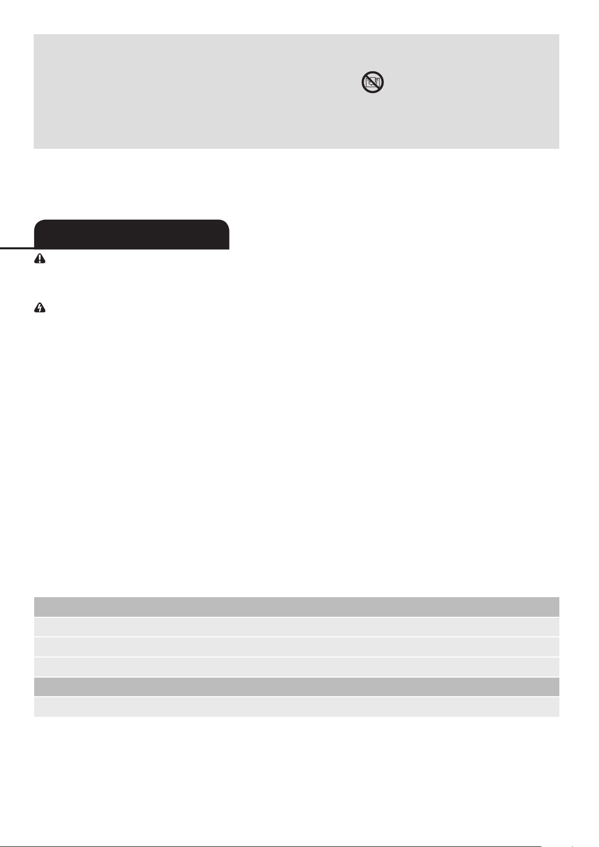
WARNING: In order to avoid overheating, do not cover the appliance. Do not place material or
garments on the appliance, or obstruct the air circulation around the appliance.
The appliance carries a DO NOT COVER warning symbol.
This appliance is equipped with a device to control the room temperature. Do not use this appliance
in small rooms when they are occupied by persons not capable of leaving the room on their own,
unless constant supervision is provided.
Thank you for choosing a Dimplex electric fire.
General Information
Dimplex Vivente Electric Fire
Models: VVT75, VVT100, VVT150
Heat Output 230V 240V
Nominal Heat Output
P
Nom
1.4 1.5 kW
Minimum Heat Output
P
min
1.3 1.4 kW
Maximum Continuous Heat Output
P
max
1.4 1.5 kW
Auxiliary Electricity Consumption
In Standby Mode
el
SB
0.49 0.49 W
with electronic room temperature control.

4
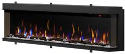
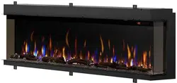
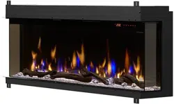
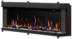
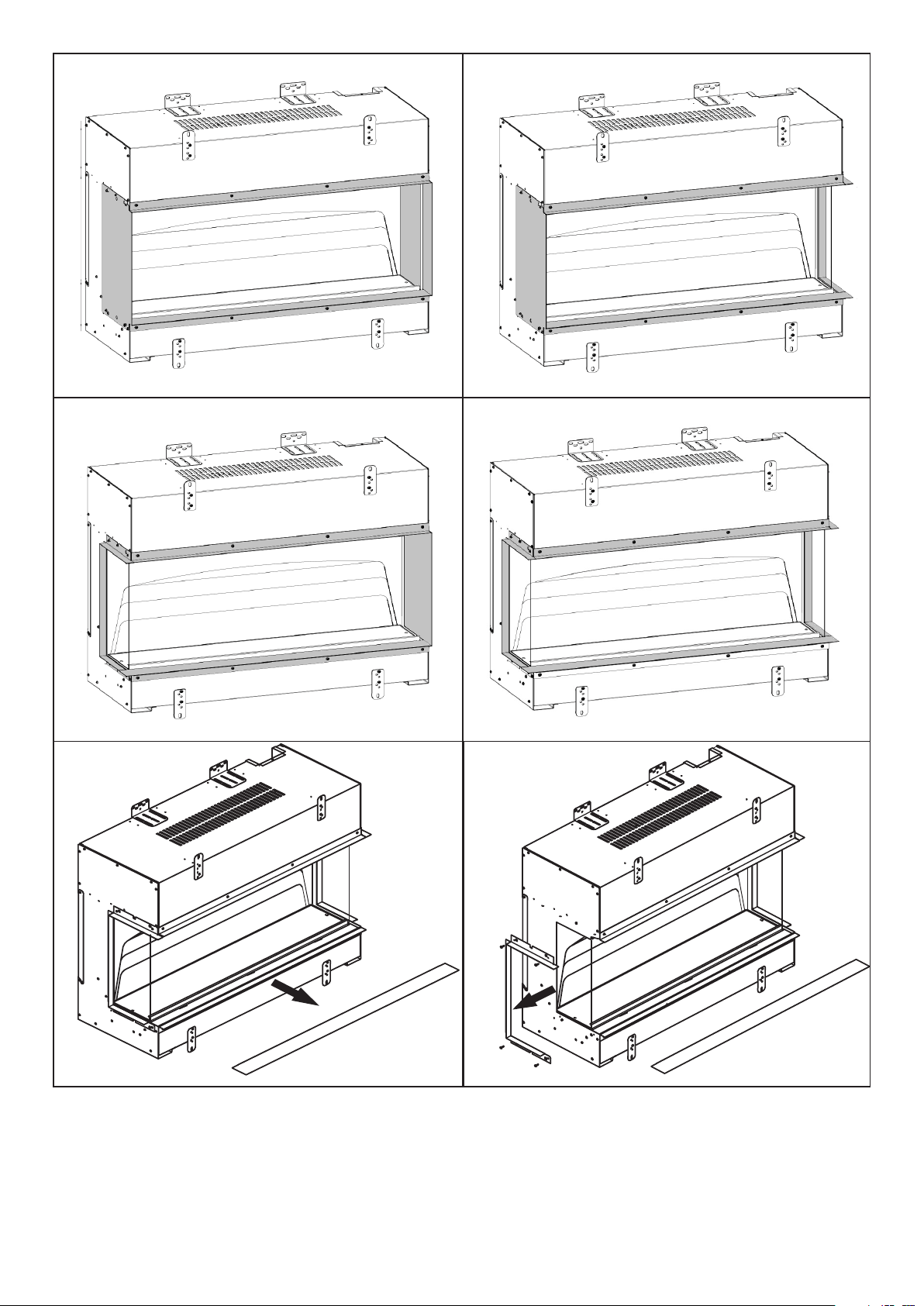
Step 1: Choosing Installation Type
The Vivente can be configured in 4 dierent ways:
• Single-sided – Front glass only (see Fig 1a)
• Two-sided Right (see Fig 1b)
• Two-sided Left (see Fig 1c)
• Three-sided (see Fig 1d).
The Vivente is supplied as a Three-sided configuration.
Please follow the steps below to adjust to your desired arrangement.
1. Remove front bottom trim on unit. See Fig. 2
2. On the desired side you wish to cover, remove side glass trim which is held in place by
four screws. Attach side panel in place of the side trim using the same four screws See Fig.
3a & 3b
3. For Front Glass Only setup, repeat Step 2 on the opposite side of product.
4. Assemble the appropriate front Trim to the product. See Fig. 2
(Three dierent trims are provided with the product to facilitate the various setup options.)
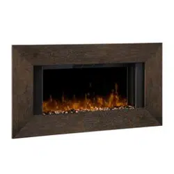
Step 2: Choosing Back Panel
The Vivente comes with two back panels, oering four dierent finishes.
The product is provided with one back panel in the unit. If you wish to change this to another
back panel design, it is advised to do so before installing the product. It is possible to fit the
back panel after the product has been installed, but it takes significantly longer and should
only be done by a qualified professional or competinent person.
All panel finishes provided contain a decorative finish, which complements the flame eect.
If so desired, these back panels can be painted with alternative colours.
The plain panel can also be painted or decorated with wallpaper to create a unique panel,
please follow the instructions on your selected paint or wallpaper adhesive, for bonding on
top of the painted MDF panel.
Please take care not to scratch these panels while storing or fitting them.
Fitting Panel – Before Installation (Recommended)
1. Remove side bracket as displayed on Fig. 4
2. The side bracket can be used to take out the back panel. Insert the bottom part of the
side bracket into the Back Panel notch, and slide out the back panel (Fig.5).
3. Place the desired back panel into position and reassemble side bracket using two screws.
Installation Instructions

5
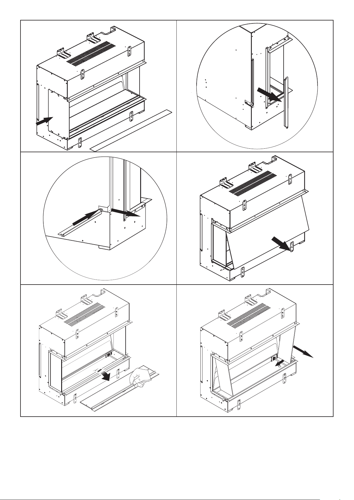
Fitting panel – After Installation
The Back Panel can also be change after the product has been installed, a person of suitable
competentancy is required to carry out this task. Please follow the steps below.
1. Disconnect product from Power Supply and remove front trim on unit. See Fig. 2
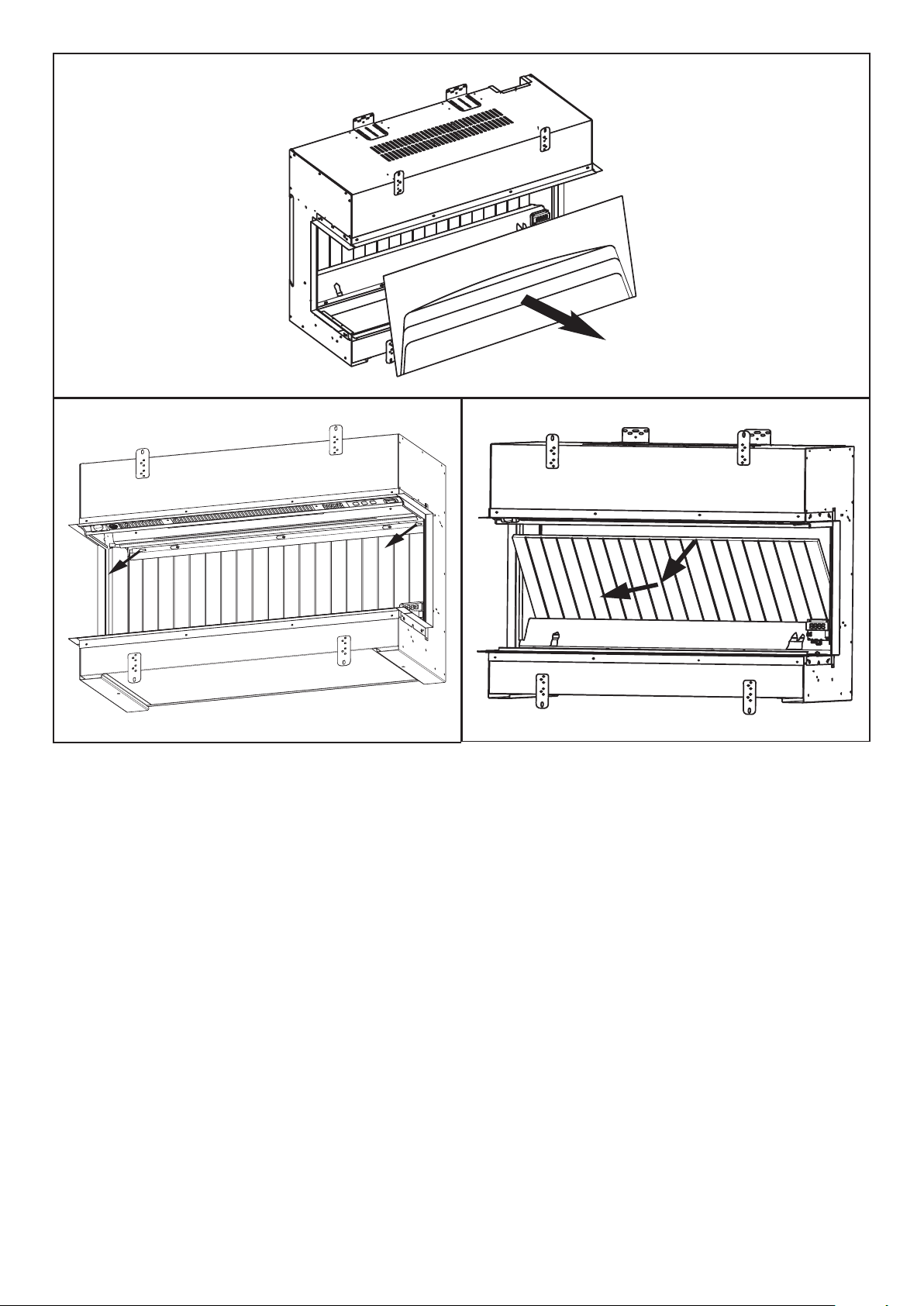
2. Remove Front Glass from product and store in a safe place. See Fig. 6 (A suction cup is
provided to help remove/replace the front glass.)
3. Remove Fuelbed fixing screws, then remove Fuelbed. (Fig. 7) It is recommeneded that the
logs are carefully removed before lifting out the fuel bed.
4. Remove both Side Glasses by tilting them in at the bottom, then sliding down and out to
remove. Store these in a safe place. (Fig. 8).
5. Remove plastic Inner Screen by tilting it from the base. (Fig.9) Use finger access provided
to allow you to contact the bottom of the screen.
6. Remove Back Inner Panel bracket (Fig. 10a), there are a number of keyhole slots which
allow for the bracket to be removed without removing the fixing screws.
Inner Back panel can then be tilted and removed from its housing. (Fig. 10b)
7. Replace with new Back Inner Panel, and reverse the steps set out above, to re-assemble
the product. Ensure Inner screen is reassembled correctly into its locating slot at the top.
(Smooth mirrored finish to face the front of the product, on the larger units an extra person
maybe required to simply the refitment of the Inner screen.)
Step 3: Installing the Product
CAUTION: Two people will be required for various steps of this procedure.
This product is designed to be installed into existing block wall or a custom-built studded
wall structure. Please consult a competent installer before undertaking this to ensure a
safe and secure installation. If installing into an existing chimney or flue, please ensure
that the chimney or flue is blocked o. This is to prevent up-draughts aecting product
operation.
Electrical Requirements
NOTE: A dedicated, properly fused 13 Amp circuit is required, rated for the appropriate
voltage (230-240V). An isolation switch should also be incorporated in cases where the
product plug is inaccessible after installation.
An access panel is provided in the base of the product, it is advisable that the plug is
located directly below this panel in the event that access is required to the plug after
installation.
WARNING: Construction and wiring must comply with local building codes and other
applicable regulations to reduce the risk of fire, electric shock and injury to persons.
WARNING: To reduce the risk of fire, electric shock or injury to persons, always use a
licensed electrician.
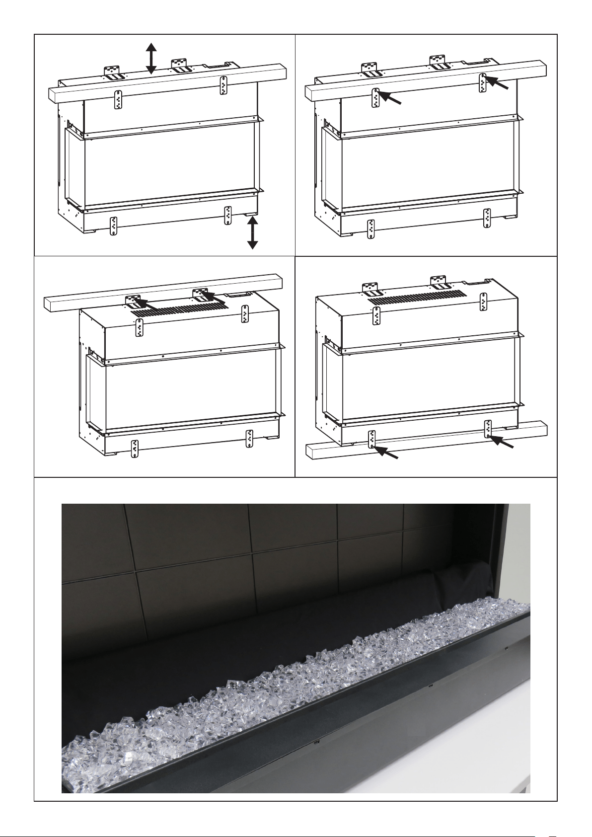
1. Using the product dimensions (Fig. 11), build a suitable structure for the product to fit
into. Ensure that, when installed, the product is within 1m of a power outlet. Please refer
to Electrical Requirements section above for more details.
It is recommended that the base of the unit is installed between 200mm and 800mm from
the floor. This is to maintain an optimised viewing angle of the fire eect. (See Fig. 12)

6
The product must not bear the weight of the finished wall located above it. Consider the
use of a lintel for appropriate support.
2.Using any combination of the three fixing methods (Fig. 13 a,b,c), fix the product to its
supporting structure.
3.Build the finished wall up against the appliance using the glass trims as a guide. The
finished wall should be built in a way that allows the power supply to be accessible after
installation.
It is recommended to leave 150mm of clearance area directly above the product for
ventilation purposes. (Fig. 12) This clearance area can be located behind the finished wall
surface.
The product should not be sealed in place with silicone or adhesive as this can restrict
airflow.
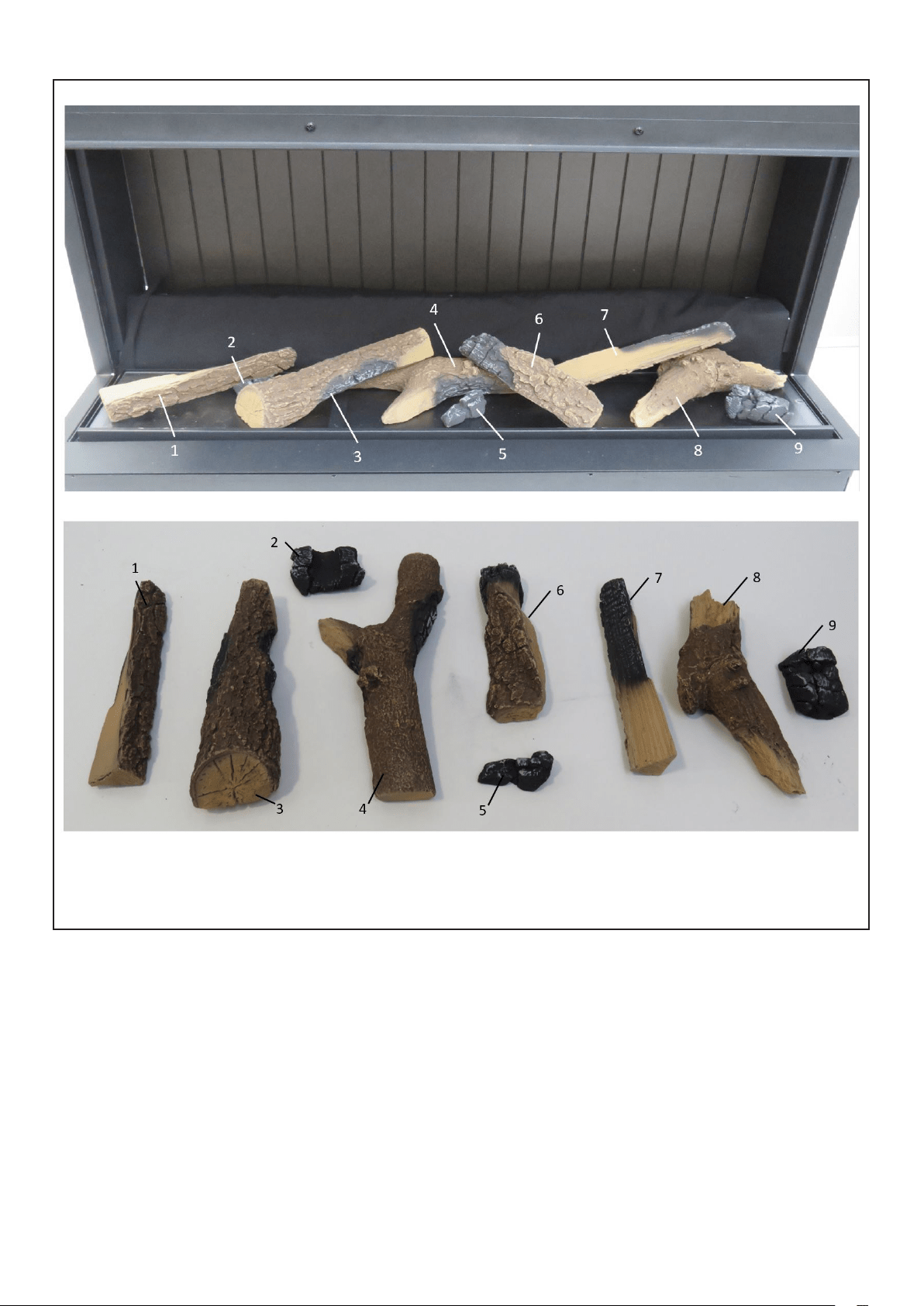
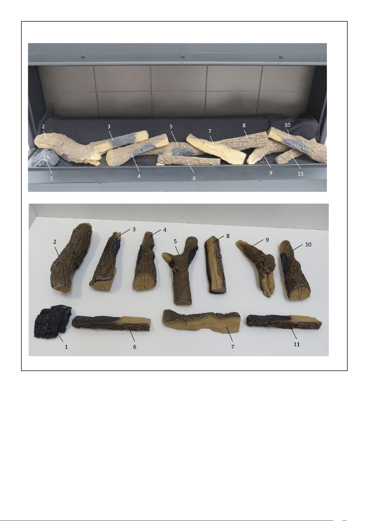
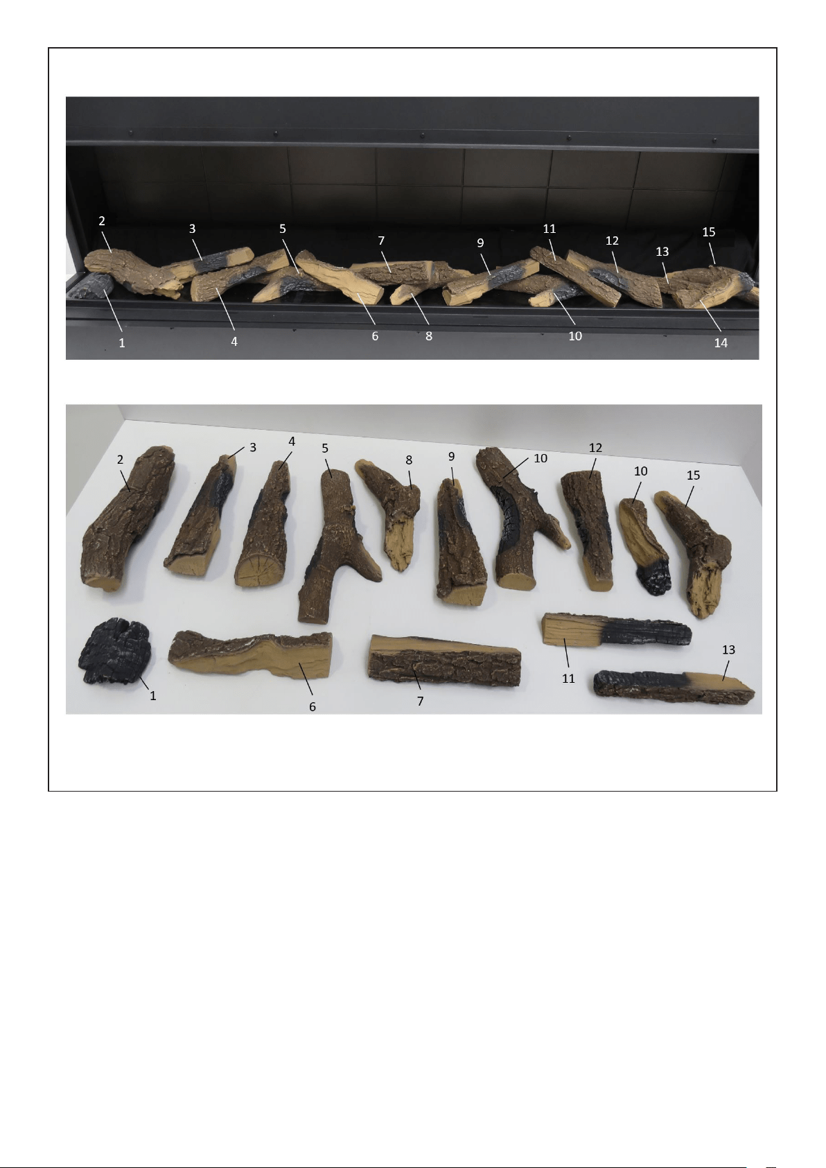
Step 4: Fuelbed Assembly
A range of fuel bed material has been provided for you to choose your desired look.
A set of high-quality ceramic logs enhance the eect of this fire. Please take great care when
handling these logs to ensure they do not get dropped or rub against each other, as they are
easily marked. The following fuel bed media is included
• Ceramic Logs
• Ash Dust
• Crystal pieces
We have taken great care to create what we feel is the most authentic fuel bed, please
follow the steps below for more information. Please note: A mix and match of fuelbed
media can also be done to create unique fuel bed assembly.
1. Remove front trim on unit. (Fig. 2)
2. Remove Front Glass from product and store in a safe place. (Fig. 6) (A suction cup is
provided to help remove/replace the front glass.)
3. For a contemporary setup (Fig.14), place crystals on fuel bed, covering the top surface of
the fuel bed. These will provide a glowing embers eect, when the flame eect is operating.
4. For a traditional look, arrange the logs on top of the fuel bed, to your preference. Please
follow the steps at the end of this document which provide a visual representation for log
arrangement. Ash dust is also supplied for this setup. Sprinkle this across the fuel bed to
produce a realistic log burning eect. (Note: Ash dust has to be placed carefully around
the logs to prevent you from seeing the fuel bed under lights in the reflective inner screen
to allow you have a realistic fuel bed As per Fig 18).
5. Reverse steps 1 and 2 to re-assemble product.

7
Operation and Use
WARNING: Failure to follow these operating instructions may result in injury and/or damage.
Thank you for choosing the Vivente. We hope you enjoy using your new electric fire. Please
take a few minutes to read these instructions. This will help you understand and benefit
from all of the following features:
• Heating – including “Comfort$aver”
• SmartSense
• On board controls
• Remote control
• App control
• Flame eects
Comfort$aver
This electric fire operates with Comfort$aver technology, which automatically adjusts the fan
speed and heater wattage to match the requirements of the room based on the thermostat
setting. Conventional electric heaters work by simply being fully on or o, which can result
in swings from slightly too warm to slightly too cold.
Comfort$aver operates such that once the room reaches the set point, the fan and heater
will continuously run at a low level, to maintain the desired room temperature providing a
more comfortable heating which results in up to an 11% energy saving.
If the temperature in the room rises significantly, i.e. sun coming through a window or the
central heating turns on, the heater will turn o and periodically turn back on to circulate
the air around the unit, until the room temperature drops and requires the heater to be
constantly on again.

8
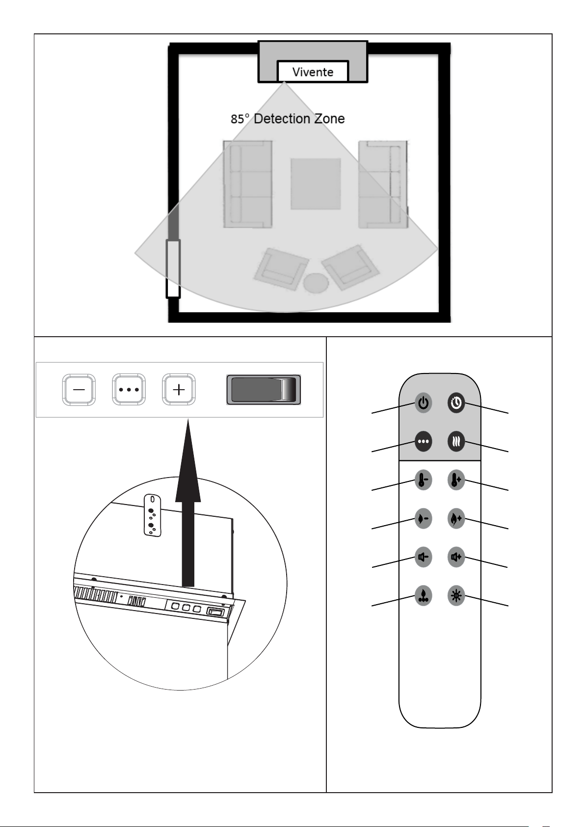
SmartSense
SmartSense detects activity or movement in a room and automatically switches on the
flame eect, without the need for you to touch the controls. SmartSense will also detect
inactivity in a room and after a certain period of time switch the product into standby mode.
See Fig. 15 which illustrates the detection zone for SmartSense.
When the fire detects no activity, it will switch itself o. You can choose either these periods
of time - 30 minutes or 3 hours.
SmartSense is deactiviated for 3 minutes after the product is put into standby mode. This
allows you to leave the room after putting the product on standby, without triggering the
SmartSense function.
SmartSense has the following three settings:
"HOME" (via APP)
On this setting SmartSense will only switch the flame eect when it detects movement
between the hours of 5-11pm, so if you enter the room during the day the fire will not
react. However in the evening, your Dimplex fire will instantly switch on your flame eect
– remembering your last setting.
"24 Hr" (Default)
SmartSense will switch on the flame eect when it detects movement at any time during
the day or night. This is ideal for retail and commercial environments.
"OFF"
SmartSense can be switched o, which will allow the product to preform normally in every
other aspect
Controls
The unit can be controlled by:
• On board/Manual controls which are located on the upper right of the fireplace (See
Fig. 16)
• Remote control – supplied
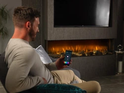
• App control. Using a dedicated App on your smart device.
Not all of the features can be accessed by the on-board controls. To access the full range
of features, the downloadable App is required.
Pairing your remote control.
To pair your remote control simple turn OFF and ON the power to the product, now press
the standby button on your remote control and your handset is now paired with your
product.
9
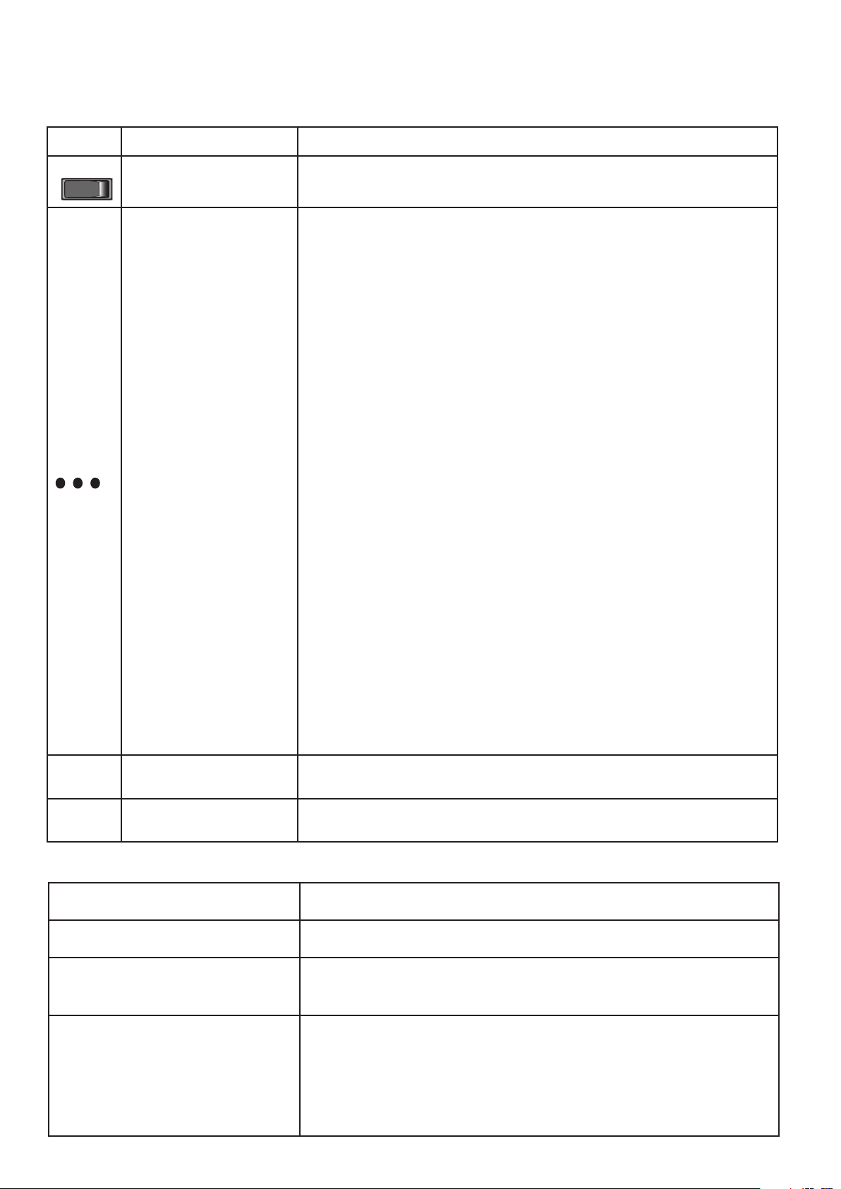
User Modes:
Mode Name /Description Action (Actions cannot be input by remote control)
Disable/Enable Heat Options
on product
When HEAT is displayed, press both the Menu Cycle Button and "-" Button for five
seconds. Display reads "CD02", heat is now disabled. Repeat to enable Heat.
Switch from Degree Celcius to Degree
Fahrenheit.
When HEAT is displayed, press both the Menu Cycle Button and "+" Button for
five seconds. The product can then switch from "-°C-" to "-°F-". Repeat to revert
back to degrees Celcius mode.
SmartSense Mode selection.
"24Hr" setting operates the SmartSense at all times. This is the default setting.
"HOME" setting; the product operates the SmartSense between 5pm and 11pm.
Please Note: The product must be connected to the "FLAME CONNECT" App, for
the"HOME" setting to operate.
Operating Instructions (ON BOARD CONTROLS)- See Figure 16
The unit can be operated using the manual controls which are located on the upper right of the fireplace.
See Fig. 16
Icon Function Description
Standby Switch
Turns product on to Standby mode. When pressed to "I", Display Board show
"ST.BY" for five seconds, then shows "." only, to indicate standby condition.
Menu Cycle Button
After initial power up, product is on standby. Press Menu Cycle Button Once: This
turns on the flame effect to a default setting. Display Board show "ON".
This button cycles through the Product setting options, when the product is
operating. These options are "FIRE", "AMB", "HEAT", "Set.T", "TIMR", "SNSR"
and "VOL".
"FIRE": The Flame Brightness Setting can then be adjusted using the "+" or "-"
buttons. There are seven settings. (Display shows "-F1-" to "-F5-", for the different
levels of brightness, "-F6-" for Pulsating Effect and "OFF" when the flame effect is
turned off.)
"AMB": The Ambient Setting can then be adjusted using the "+" or "-" buttons.
There are seven settings available on the onboard controls. (Display shows
"AMB1" to "AMB7") "AMB8" is a customisable mood setting that is available via
the Dimplex Flame Connect App. Please Note: "-F6-" is not an available setting
when in "AMB6", "AMB7" or "AMB8".
"HEAT": The set temperature "XXST" is displayed for two seconds, after that, the
room temperature "XX°C" for a further two seconds. The Heat Setting can be
switched ON/OFF using the "+" or "-" buttons respectively. (Display shows "ON"
or "OFF")
"Set.T": The Set Temperature can then be adjusted using the "+" or "-" buttons.
Temperature range is 15°C - 32°C and is in increments of 1°C (Display shows
"15ST" up to "32ST")
"TIMR": The Runback Timer can be adjusted using the "+" or "-" buttons. This can
be set between 0.5 Hrs and 8.0 Hrs in increments of 0.5 hrs. ("0.5Hr" to "8.0 Hr +
OFF")
"SNSR": The SmartSense Settings can be adjusted using the "+" or "-" buttons.
"MIN" turns product off 0.5 hour after last movement detected."MAX" turns
product off 3 hour after last movement detected. "OFF" - Motion Sensor turned
off.
"VOL": The Volume can be adjusted using the "+" or "-" buttons. Volume has
seven settings. ("OFF", which is sound off and "VOL1" to "VOL6")
Increase "+" Button
This button increases the displayed setting when it is pressed, while in Menu Mode.
Decrease "-" Button
This button decreases the displayed setting when it is pressed, while in Menu
Cycle Mode.
+
-
I
0
10
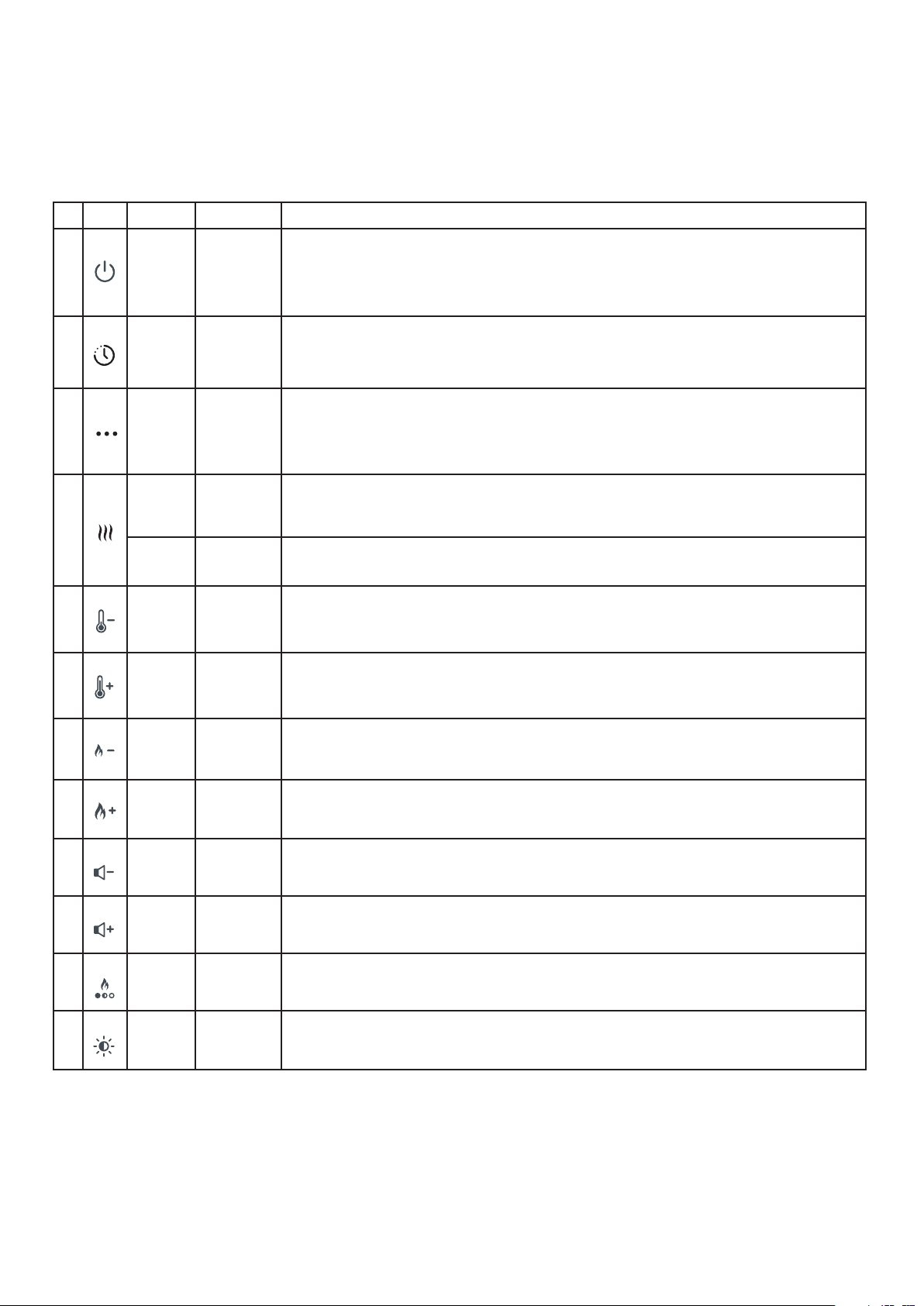
Operating Instructions using REMOTE CONTROL - See Figure 17
Icon Display Funtion Description
A
"FIRE" /
"ST.BY"
Power /
Standby
Press Once to turn the product on. ("ON")
Press a second time to put the product into standby. ("ST.BY" is shown, then "." is displayed
to indicate standby.)
(When returning from ‘STANDBY’ mode the product will return to previous settings unless the
product has been unplugged, in which case it will reset to factory settings)
B "TIMR"
Timer
Cycle
This Button changes the timer setting. This can be set between 0.5 Hrs and 8.0Hrs in incre-
ments of 0.5 hrs. ("0.5Hr" to "8.0Hr + OFF") Each Button press will increase timer setting by
0.5hrs.
C "SNSR"
Smart-
Sense
Cycle
This Button cycles through the SmartSense settings. Display will read; "MIN", "MAX" or
"OFF".
"MIN" turns product off 0.5 hour after last movement detected in room.
"MAX" turns product off 3 hour after last movement detected in room.
"OFF" - SmartSense is turned off
D
"ON" Heat Mode
First Button press activates the heat. Display reads "ON - XXST - XX
0
C"
"OFF" Heat Mode
Second button press deactivaes the heat. Display shows "OFF"
E "15ST"
Temp
Down
Press Once to display current Set Temperature.
Press multiple times to lower the heater temperature in 1
0
C increments. The lowest
temperature that can be set is 15
0
C.
F "32ST" Temp Up
Press Once to display current Set Temperature.
Press multiple times to increase the heater temperature in 1
0
C increments. The highest
temperature that can be set is 32
0
C.
G "-F1-"
Flame
Brightness
Down
Press Once to display current flame brightness setting.
Press to reduce the flame brightness setting. Range is from "-F1-" to "-F6-" and "OFF".
H "-F6-"
Flame
Brightness
Up
Press Once to display current flame brightness setting.
Press to increase the flame brightness setting. Range is "OFF", then "-F1-" to "-F6-"
I "VOL1"
Volume
Down
Press Once to display current volume setting.
Press to reduce the volume setting. Range is "OFF", then "VOL1" to "VOL6".
J "VOL6"
Volume
Up
Press Once to display current volume setting.
Press to increase the volume setting. Range is "OFF", then "VOL1" to "VOL6".
K "AMB1"
Ambient
Cycle
Press once to display current Ambient Setting. Subsequent presses will cycle trhough the
settings. Range is from "AMB1" to "AMB7". "AMB8" will also display once it is activated via
the app.
L "LGT1"
Light
Selection
Button
Press once to show all toplights and fuelbed and flame colour lights ON. Subsequent
presses cycle through ON/OFF settings for each of these lights. "ON" to "LGT4"
Remote control
The fireplace is supplied with a remote control.
11
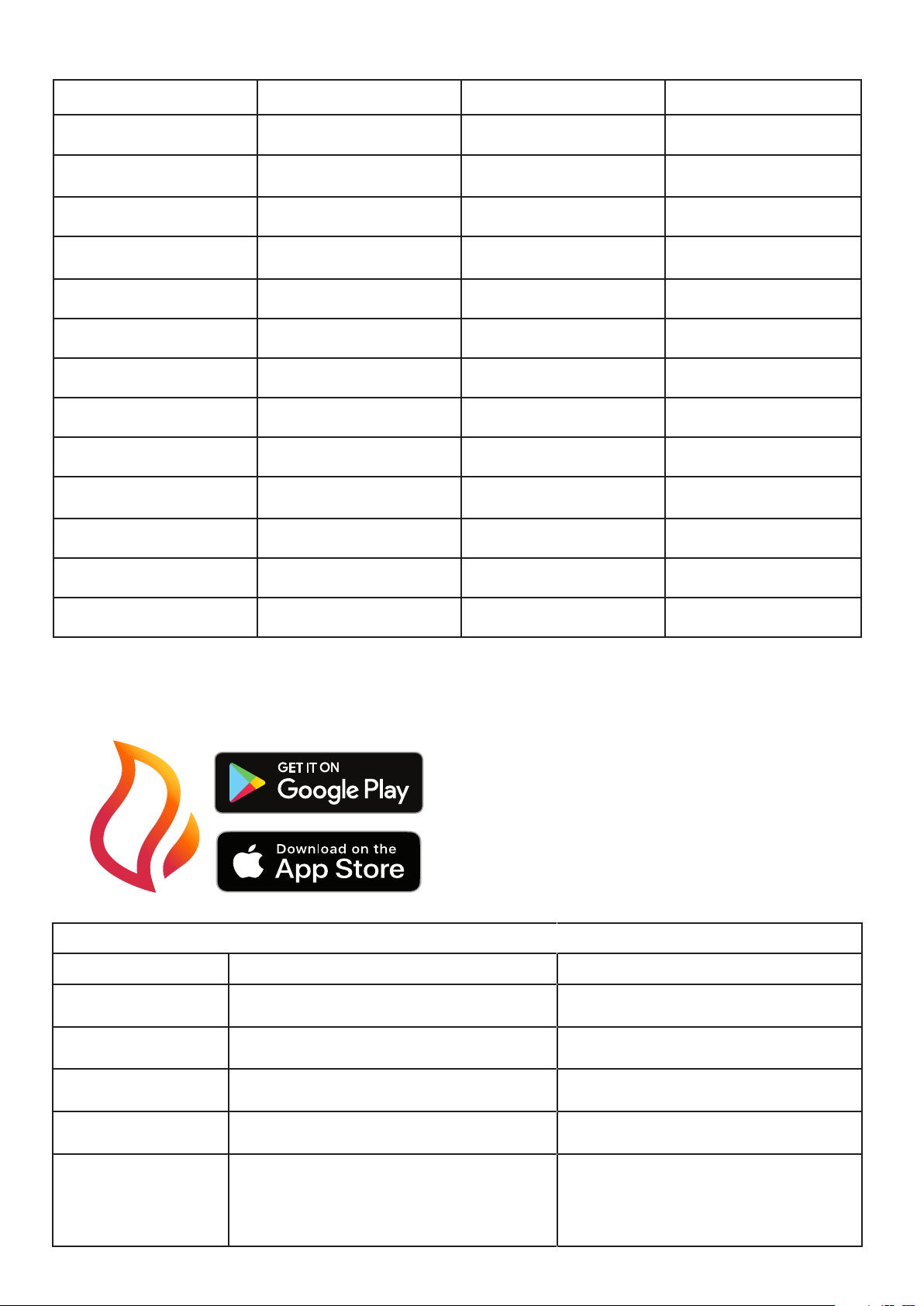
Smart Phone App
“Flame Connect” allows you to control your fire's function over Bluetooth, from your hand.
Search for “Flame Connect” on your App Store and install to get started.
Function On Board Controls Remote Control App Control
Standby ✓ ✓ ✓
Temperature Adjustment (15
- 32C)
✓ ✓ ✓
Heat Disable ✓ - -
Heater Mode (ECO, Boost,
Frost Protection, Fan)
- - ✓
Flame Intensity ✓ ✓ ✓
Volume Setting ✓ ✓ ✓
Run-back Timer ✓ ✓ ✓
7 - Day Timer - - ✓
Volume Setting ✓ ✓ ✓
Ambient Light Setting ✓ ✓ ✓
Ambient Light On/O - ✓ ✓
Customizable Ambient - - ✓
SmartSense ✓ ✓ ✓
Product Features Overview
Fault Codes
On Board Display Description Action
CD20
Room Sensor (NTC) Error Contact your retailer and reference this error
code.
CD03
The internal NTC is measuring elevated tempera-
tures within the product.
Unplug Unit at power supply to reset, allow it
to cool down, then plug unit back in to restart.
CD04
Internal Communication Error Contact your retailer and reference this error
code.
CD05
The internal temperature sensor has failed. Unplug Unit at power supply to reset, allow it
to cool down, then plug unit back in to restart.
CD53
This error displays when timer settings are out of
sync. This occurs when the product has power cut
o for over 40hours. The product can no longer
operate at the determined time settings, and CD53
is displayed.
Reset the timer settings using the Flame Con-
nect APP.

12
WARNING: ALWAYS DISCONNECT FROM THE POWER SUPPLY BEFORE CLEANING
THE HEATER.
Cleaning
Before commencing cleaning, unplug the heater and allow it to cool.The surfaces of the
heater should be given an occasional wipe with a dry soft cloth. Do not use detergents,
abrasive cleaning powder or furniture polish as this can damage the surface finish of the
product.
To remove any accumulation of dust or flu, the soft brush attachment of a vacuum cleaner
should occasionally be used to clean the outlet grille of the fan heater located above the
front glass.
To clean the fuel eect, remove the fuelbed media. The plastic tray should be wiped clean
with a damp cloth. When dry, replace the logs/crystals onto the fuelbed and arrange for
best eect.
The front and side glass is cleaned in the factory during the assembly operation. During
shipment, installation, handling, etc., the front and side glass may collect dust particles;
these can be removed by dusting lightly with a clean dry cloth.
To remove fingerprints or other marks, the partially reflective glass can be cleaned with a
damp cloth. The partially reflective glass should be completely dried with a lint free cloth to
prevent water spots. To prevent scratching, do not use abrasive cleaners.
CAUTION: Assembly, installation and repair of this heater must be carried out by Dimplex
or its authorised agent.
CAUTION: We recommend that this heater is checked annually for safety by a qualified
electrician.
Flame effect themes
There are different combinations of flame effect available. Different presets of lighting colour
combinations are available and can be cycled through using the remote control.
Further customisation of the effects is accessible through the smart phone app.
Resetting the Temperature Cutoff Switch
Should the heater overheat, an automatic cut out will turn the whole unit off and it will
not come back on without being reset. It can be reset by turning the unit off at the main
power and waiting 5 minutes before turning the unit back on. See table Fault Codes on the
previous page for more details.
CAUTION: If you need to continuously reset the heater, turn the unit off at the main
supply, and call technical support.
Maintenance
13
After Sales Service
Your product is guaranteed for one year from the date of purchase. Within this period, we
undertake to repair or exchange this product free of charge provided it has been installed
and operated in accordance with these instructions. Your rights under this guarantee are
additional to your statutory rights, which in turn are not aected by this guarantee.
CAUTION: Do not use if the heater’s mains power lead is damaged. Such use may cause
a hazard. If damaged, the mains power lead must be replaced by the manufacturer or its
authorised dealer.
Should you require after sales information or assistance with this product please go to
www.dimplex.co.uk and select “Customer Support” or ring our help desk on 0844 879
3588 (UK) or 01 842 8222 (R. O. I.). Spare parts are also available on the web site. Please
retain your receipt as proof of purchase.
Recycling
For electrical products sold within the European Community - At the end of the
electrical products useful life it not be disposed of with household waste. Please
recycle where facilities exist. Check with your Local Authority or retailer for recycling
advice in your country.
Additional Information
14
Fig. 2 Fig. 3a
Fig. 1a
Fig. 1b
Fig. 1c Fig. 1d
15
Fig. 5
Fig. 7
Fig. 8
Fig. 4
Fig. 3b
Fig. 6
1
2
1
2
16
Fig. 10a
Fig. 10b
Fig. 9

17
‘X’
310
200 - 800
670
Fig. 11
MODEL ‘X’
VVT75 764mm
VVT100 1014mm
VVT150 1514mm
X
X + 30mm
321
666
350
120
172
307
18
Fig. 14
Fig. 13a
Fig. 13c
Fig. 13b
Fig. 12
150mm
200 - 800mm
19
Fig. 17
Fig. 16
A
C
E
G
I
K
B
D
F
H
J
L
Fig. 15
I
0
20
VVT75
21
VVT100
22
VVT150

23
Fig. 18

24
Tel: 0344 879 3588
Republic of Ireland Tel: 01 8428 222
www.dimplex.co.uk
Dimplex Millbrook House, Grange Drive, Hedge End, Southampton, SO30 2DF
© Glen Dimplex Heating and Ventilation.
All rights reserved. Material contained in this publication may not be reproduced in whole or in part, without prior permission
in writing of Glen Dimplex Heating and Ventilation.