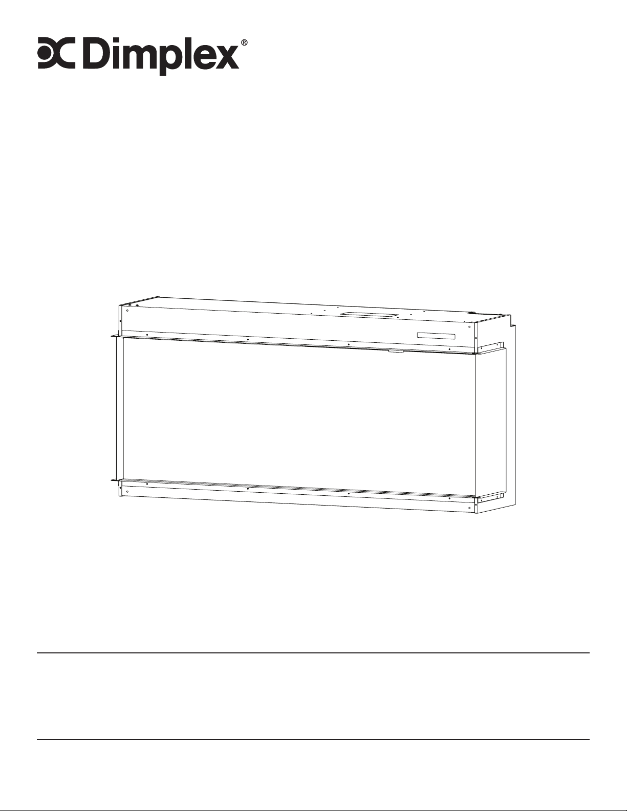
Service Manual
IMPORTANT SAFETY INFORMATION:
Read this manual first before attempting to install or use this electric fireplace. Always comply with the
warnings and safety instructions contained in this manual to prevent personal injury or property damage.
7401140100R03
XLF5017-XD - 6911580000
XLF6017-XD - 6911590000
XLF7417-XD - 6911600000
XLF8817-XD - 6911610000
XLF10017-XD - 6911620000
Models

2 www.dimplex.com
Exploded Parts Diagrams ......................................................3
XLF5017-XD Replacement Parts List .............................................3
XLF6017-XD Replacement Parts List .............................................4
XLF7417-XD Replacement Parts List .............................................5
XLF8817-XD Replacement Parts List .............................................6
XLF10017-XD Replacement Parts List ............................................7
Wiring Diagrams ..............................................................8
XLF5017-XD ................................................................8
XLF6017-XD ................................................................8
XLF7417-XD ................................................................9
XLF8817-XD ................................................................9
XLF10017-XD ...............................................................9
Replacement Part Procedures .................................................10
Preparing the Firebox for Service ...............................................10
Heater Assembly Replacement ................................................11
Main Control Board Replacement ..............................................12
Power Supply Replacement ...................................................13
Relay Board Replacement ....................................................14
Adapter Board Replacement (XLF8817-XD & XLF10017-XD) .........................14
Hidden Touch Controls Replacement............................................15
Temperature Sensor (NTC) Replacement .........................................16
Flicker Motor Replacement ...................................................17
Flame LED Replacement .....................................................18
Media Bed LED Replacement .................................................19
Overhead LED Replacement ..................................................20
Troubleshooting .............................................................21
App ......................................................................22
Conventions used in this manual:
!
NOTE: Procedures and techniques that are considered important enough to emphasize.
CAUTION: Procedures and techniques which, if not carefully followed, will result in damage to the equipment.
WARNING: Procedures and techniques which, if not carefully followed, will expose the user to the risk of re,
serious injury, or death.
Table of Contents
3
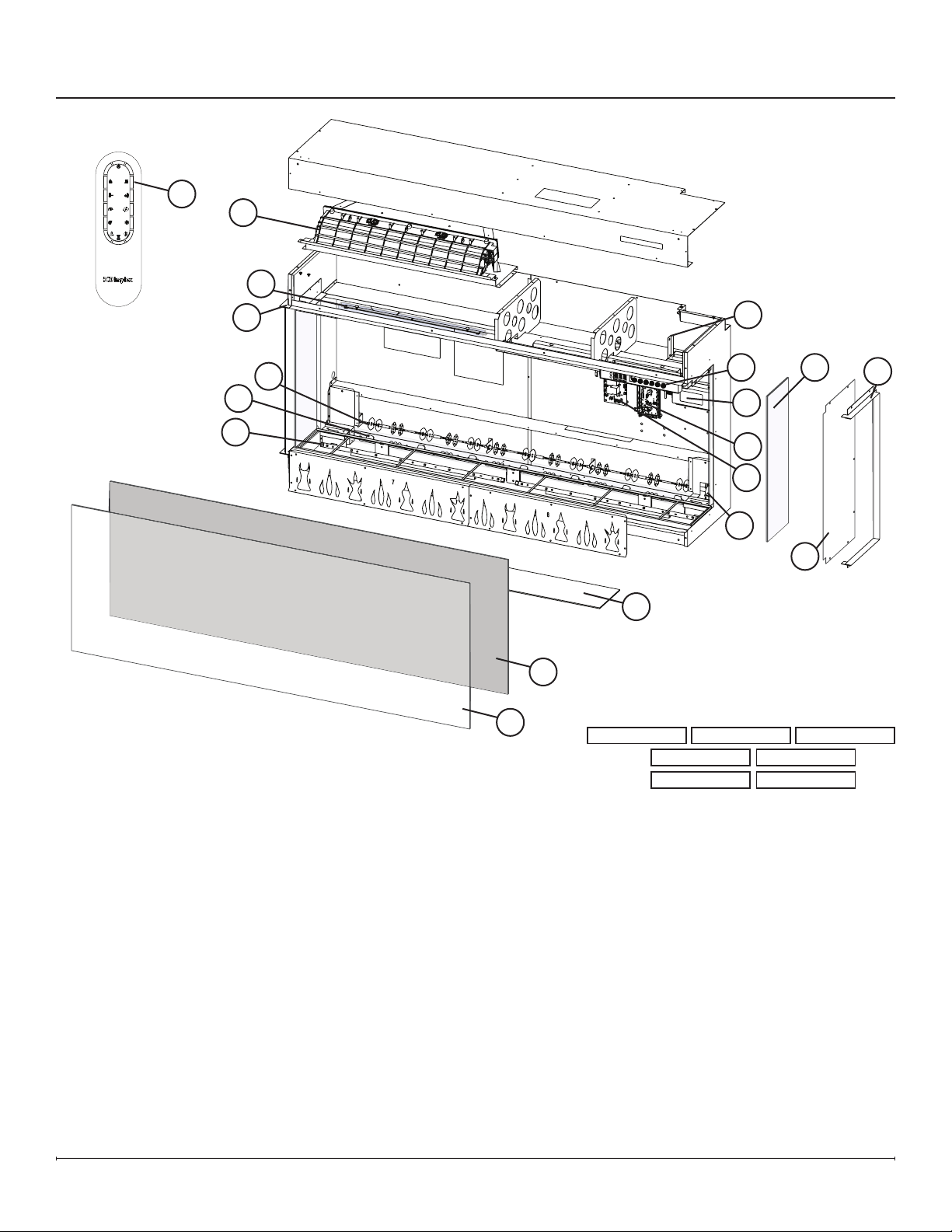
Exploded Parts Diagrams
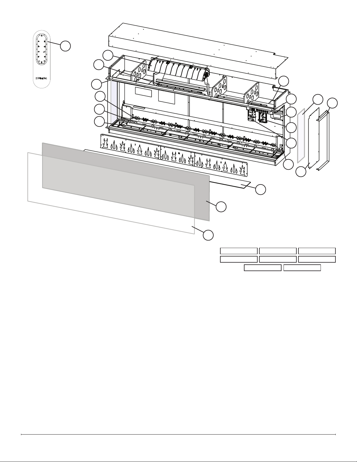
XLF5017-XD Replacement Parts List
1. Remote Control .................X-3002310100RP
2. Heater Assembly. . . . . . . . . . . . . . . . X-2203860100RP
3. Power Supply ..................X-2100250500RP
4. Main Control Board. . . . . . . . . . . . . . . . . . . 500002258
5. Relay Board ........................500002277
6. Hidden Touch Controls . . . . . . . . . . . . . . . . 500002274
7. Temperature Sensor (NTC) ........X-3001560600RP
8. Flicker Motor. . . . . . . . . . . . . . . . . . . X-2000550100RP
9. Flicker Rod ....................X-5903960100RP
10. Flame LED Strip (2) . . . . . . . . . . . . . . X-3002320100RP
(1). . . . . . . . . . . . . . X-3002320200RP
11. Media LED Strip (2) . . . . . . . . . . . . . . X-3002350300RP
12. Overhead LED Strip (2) . . . . . . . . . . . X-3002350200RP
13. Mirrored Glass .................X-5903780100RP
14. Front Glass ....................X-5903760100RP
15. Side glass (includes 1) ...........X-5903770100RP
16. Media Tray ....................X-5903790100RP
17. Medium Acrylic Crystals . . . . . . . . . . X-1400150300RP
..................................(2 required)
18. Large Acrylic Crystals . . . . . . . . . . . . X-1400130500RP
19. Extra-large Acrylic Crystals. . . . . . . . X-1400170300RP
20. Driftwood .....................X-0478800100RP
21. Trim Assembly. . . . . . . . . . . . . . . . . . X-1037390100RP
22. Hardware Kit . . . . . . . . . . . . . . . . . . . X-9602620400RP
23. Side Panel (includes 1) ...........X-1033820100RP
1
2
3
4
5
6
8
9
10
11
12
13
14
15
16
7
21
LED Conguration
Overhead
Flame
Media
3002350300RP 3002350300RP
3002320100RP3002320200RP 3002320100RP
3002350200RP 3002350200RP
21
23
4 www.dimplex.com
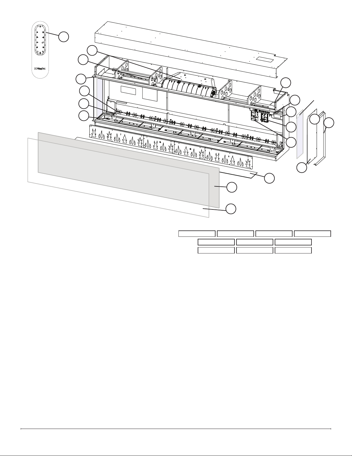
XLF6017-XD Replacement Parts List
1. Remote Control .................X-3002310100RP
2. Heater Assembly. . . . . . . . . . . . . . . . X-2203860100RP
3. Power Supply ..................X-2100250500RP
4. Main Control Board. . . . . . . . . . . . . . . . . . . 500002258
5. Relay Board ........................500002277
6. Hidden Touch Controls . . . . . . . . . . . . . . . . 500002275
7. Temperature Sensor (NTC) ........X-3001560600RP
8. Flicker Motor. . . . . . . . . . . . . . . . . . . X-2000550100RP
9. Flicker Rod ....................X-5903960200RP
10. Flame LED Strip (1) . . . . . . . . . . . . . . X-3002320200RP
(2). . . . . . . . . . . . . . X-3002320300RP
11. Media LED Strip (2) . . . . . . . . . . . . . . X-3002350200RP
(1). . . . . . . . . . . . . . X-3002350300RP
12. Overhead LED Strip (2) . . . . . . . . . . . X-3002350200RP
13. Mirrored Glass .................X-5903780200RP
14. Front Glass ....................X-5903760200RP
15. Side glass (includes 1) ...........X-5903770100RP
16. Media Tray ....................X-5903790200RP
17. Medium Acrylic Crystals . . . . . . . . . . X-1400150300RP
..................................(3 required)
18. Large Acrylic Crystals . . . . . . . . . . . . X-1400130600RP
19. Extra-large Acrylic Crystals. . . . . . . . X-1400170400RP
20. Driftwood .....................X-0478800200RP
21. Trim Assembly. . . . . . . . . . . . . . . . . . X-1037390200RP
22. Hardware Kit . . . . . . . . . . . . . . . . . . . X-9602620200RP
23. Side Panel (includes 1) ...........X-1033820100RP
LED Conguration
Overhead
Flame
Media
3002320300RP
3002350300RP
3002320200RP
3002350200RP
3002320300RP
3002350200RP
3002350200RP 3002350200RP
2
3
4
5
6
8
9
10
11
12
13
14
1
7
15
16
21
21
23
5
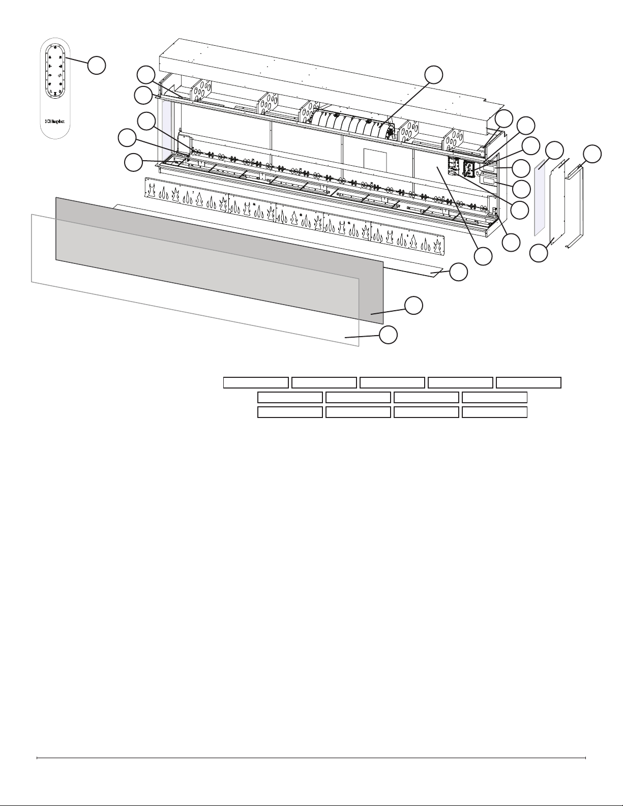
XLF7417-XD Replacement Parts List
1. Remote Control .................X-3002310100RP
2. Heater Assembly. . . . . . . . . . . . . . . . X-2203860100RP
3. Power Supply ..................X-2100250500RP
4. Main Control Board. . . . . . . . . . . . . . . . . . . 500002258
5. Relay Board ........................500002277
6. Hidden Touch Controls . . . . . . . . . . . . . . . . 500002276
7. Temperature Sensor (NTC) ........X-3001560600RP
8. Flicker Motor. . . . . . . . . . . . . . . . . . . X-2000550100RP
9. Flicker Rod ....................X-5903960300RP
10. Flame LED Strip (1) . . . . . . . . . . . . . . X-3002320100RP
(1). . . . . . . . . . . . . . X-3002320200RP
(2). . . . . . . . . . . . . . X-3002320300RP
11. Media LED Strip (3) . . . . . . . . . . . . . . X-3002350300RP
12. Overhead LED Strip (3) . . . . . . . . . . . X-3002350200RP
13. Mirrored Glass .................X-5903780300RP
14. Front Glass ....................X-5903760300RP
15. Side glass (includes 1) ...........X-5903770100RP
16. Media Tray ....................X-5903790300RP
17. Medium Acrylic Crystals . . . . . . . . . . X-1400150300RP
..................................(3 required)
18. Large Acrylic Crystals . . . . . . . . . . . . X-1400130700RP
19. Extra-large Acrylic Crystals. . . . . . . . X-1400170500RP
20. Driftwood .....................X-0478800300RP
21. Trim Assembly. . . . . . . . . . . . . . . . . . X-1037390300RP
22. Hardware Kit . . . . . . . . . . . . . . . . . . . X-9602620400RP
23. Side Panel (includes 1) ...........X-1033820100RP
LED Conguration
Overhead
Flame
Media
3002320300RP
3002350300RP
3002350200RP
3002320100RP3002320200RP
3002350300RP
3002350200RP
3002320300RP
3002350300RP
3002350200RP
13
14
1
15
16
21
2
3
4
5
6
9
10
11
12
7
21
23
6 www.dimplex.com
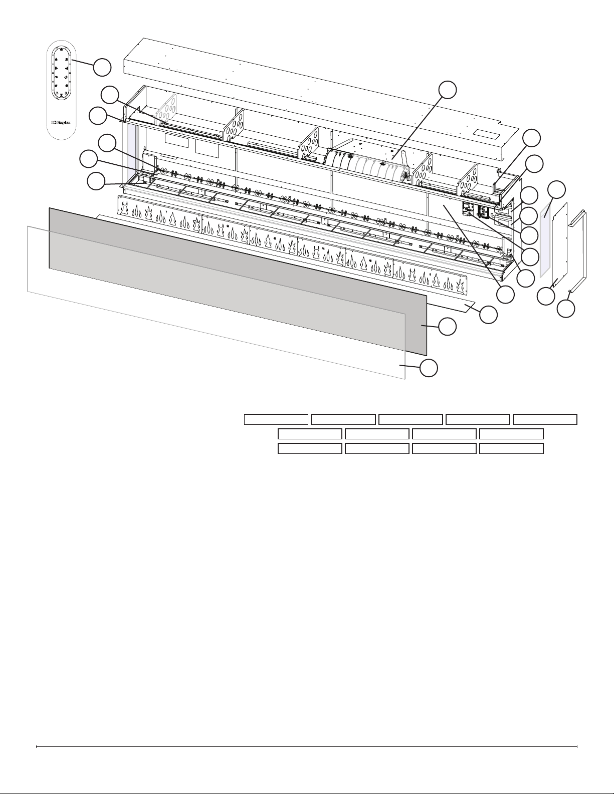
XLF8817-XD Replacement Parts List
1. Remote Control .................X-3002310100RP
2. Heater Assembly. . . . . . . . . . . . . . . . X-2203860100RP
3. Power Supply (5 AMP) ...........X-2100250500RP
4. Power Supply (3 AMP) ...........X-2100250600RP
5. Main Control Board. . . . . . . . . . . . . . . . . . . 500002258
6. Adapter Board. . . . . . . . . . . . . . . . . . X-3002400100RP
7. Relay Board ........................500002277
8. Hidden Touch Controls . . . . . . . . . . . . . . . . 500002262
9. Temperature Sensor (NTC) ........X-3001560600RP
10. Flicker Motor. . . . . . . . . . . . . . . . . . . X-2000550100RP
11. Flicker Rod ....................X-5903960400RP
12. Flame LED Strip (2) . . . . . . . . . . . . . . X-3002320100RP
(1). . . . . . . . . . . . . . X-3002320200RP
(2). . . . . . . . . . . . . . X-3002320300RP
13. Media LED Strip (2) . . . . . . . . . . . . . . X-3002350200RP
(2). . . . . . . . . . . . . . X-3002350300RP
14. Overhead LED Strip (1) . . . . . . . . . . . X-3002350100RP
(3) . . . . . . . . . . . X-3002350200RP
15. Mirrored Glass .................X-5903780400RP
16. Front Glass ....................X-5903760400RP
17. Side glass (includes 1) ...........X-5903770100RP
18. Media Tray ....................X-5903790400RP
19. Medium Acrylic Crystals . . . . . . . . . . X-1400150300RP
..................................(4 required)
20. Large Acrylic Crystals . . . . . . . . . . . . X-1400130400RP
21. Extra-large Acrylic Crystals. . . . . . . . X-1400170600RP
22. Driftwood .....................X-0478800400RP
23. Trim Assembly. . . . . . . . . . . . . . . . . . X-1037390400RP
24. Hardware Kit . . . . . . . . . . . . . . . . . . . X-9602620400RP
25. Side Panel (includes 1) ...........X-1033820100RP
LED Conguration
Overhead
Flame
Media
3002320100RP
3002350300RP
3002350200RP
3002320200RP3002320300RP
3002320300RP
3002350300RP3002350300RP
3002350300RP 3002350200RP
3002320100RP
3002350300RP
3002350300RP
1
2
3
4
5
6
8
9
10
11
12
13
14
15
16
17
18
7
23
23
25
7
1. Remote Control .................X-3002310100RP
2. Heater Assembly. . . . . . . . . . . . . . . . X-2203860100RP
3. Power Supply (5 AMP) ...........X-2100250500RP
4. Power Supply (3 AMP) ...........X-2100250600RP
5. Main Control Board. . . . . . . . . . . . . . . . . . . 500002258
6. Adapter Board. . . . . . . . . . . . . . . . . . X-3002400100RP
7. Relay Board ........................500002277
8. Hidden Touch Controls . . . . . . . . . . . . . . . . 500002263
9. Temperature Sensor (NTC) ........X-3001560600RP
10. Flicker Motor. . . . . . . . . . . . . . . . . . . X-2000550100RP
11. Flicker Rod ....................X-5903960500RP
12. Flame LED Strip (1) . . . . . . . . . . . . . . X-3002320200RP
(4). . . . . . . . . . . . . . X-3002320300RP
13. Media LED Strip (4) . . . . . . . . . . . . . . X-3002350300RP
14. Overhead LED Strip (4) . . . . . . . . . . . X-3002350200RP
15. Mirrored Glass .................X-5903780500RP
16. Front Glass ....................X-5903760500RP
17. Side glass (includes 1) ...........X-5903770100RP
18. Media Tray ....................X-5903790500RP
19. Medium Acrylic Crystals . . . . . . . . . . X-1400150300RP
..................................(4 required)
20. Large Acrylic Crystals . . . . . . . . . . . . X-1400130800RP
21. Extra-large Acrylic Crystals. . . . . . . . X-1400170700RP
22. Driftwood .....................X-0478800500RP
23. Trim Assembly. . . . . . . . . . . . . . . . . . X-1037390500RP
24. Hardware Kit . . . . . . . . . . . . . . . . . . . X-9602620400RP
25. Side Panel (includes 1) ...........X-1033820100RP
XLF10017-XD Replacement Parts List
LED Conguration
Overhead
Flame
Media
3002320300RP
3002350300RP
3002350200RP
3002320300RP3002320300RP
3002320300RP
3002350300RP3002350300RP
3002350200RP 3002350200RP
3002320200RP
3002350300RP
3002350200RP
1
2
3
4
5
6
8
9
10
11
12
13
14
15
16
17
18
7
23
23
25
8 www.dimplex.com
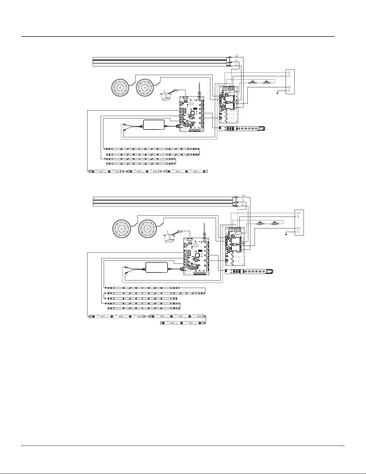
XLF6017-XD
Wiring Diagrams
XLF5017-XD
Overhead LEDs
Cut-outs
Relay Board
Hidden Touch Controls
Main Control Board
Flicker Motor
Heating Element
5 Amp Power Supply
Fan Fan
Media Bed LEDs
Flame LEDs
Overhead LEDs
Cut-outs
Relay Board
Hidden Touch Controls
Main Control Board
Flicker Motor
Heating Element
5 Amp Power Supply
Fan Fan
Media Bed LEDs
Flame LEDs
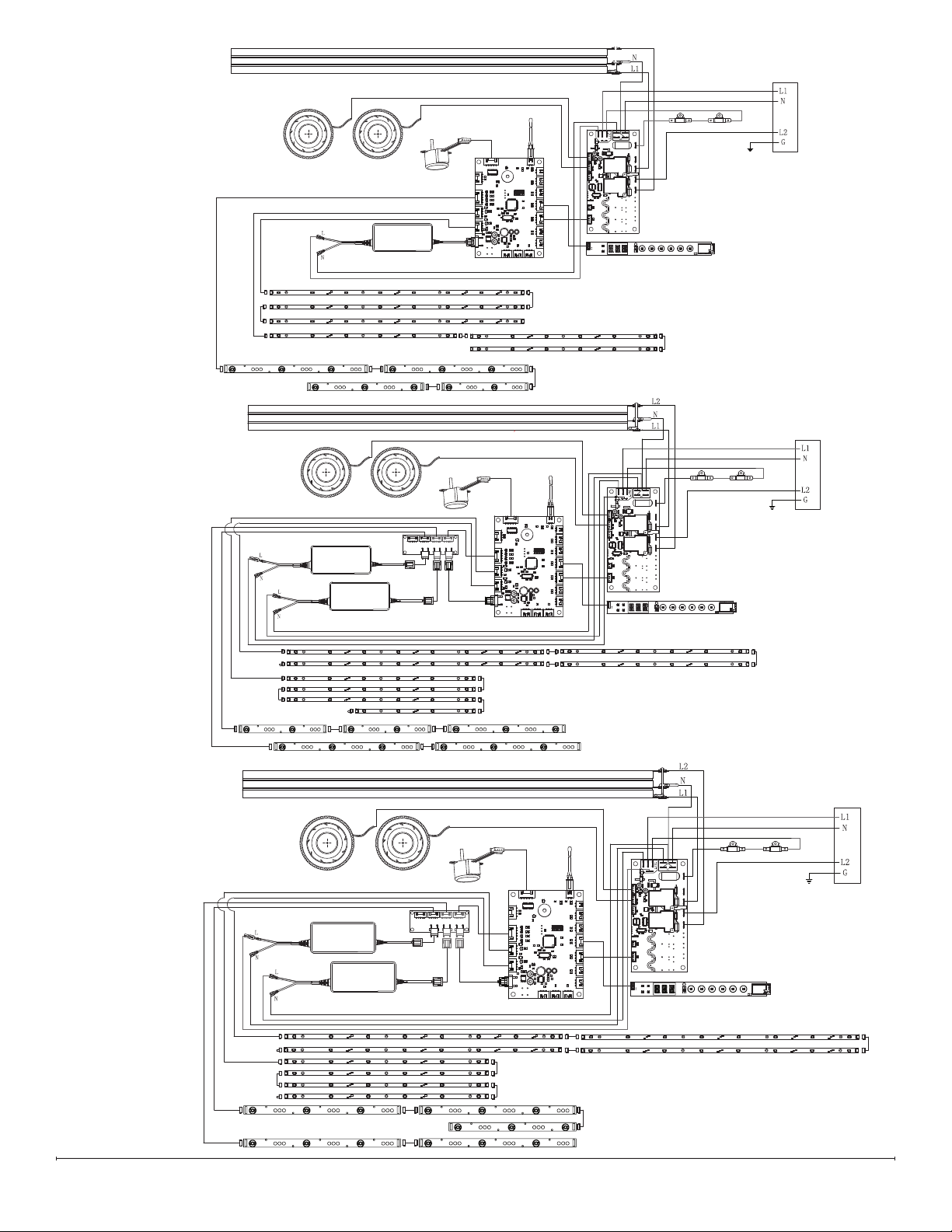
9
XLF7417-XD
XLF8817-XD
XLF10017-XD
Overhead LEDs
Cut-outs
Relay Board
Hidden Touch Controls
Main Control Board
Flicker Motor
Heating Element
5 Amp Power Supply
Fan Fan
Media Bed LEDs
Flame LEDs
Overhead LEDs
Cut-outs
Relay Board
Hidden Touch Controls
Adapter
Board
Flicker Motor
Heating Element
5 Amp Power Supply
3 Amp Power Supply
Fan Fan
Media Bed LEDs
Flame LEDs
Main Control Board
Overhead LEDs
Cut-outs
Relay Board
Hidden Touch Controls
Adapter
Board
Flicker Motor
Heating Element
5 Amp Power Supply
3 Amp Power Supply
Fan Fan
Media Bed LEDs
Flame LEDs
Main Control Board
10 www.dimplex.com
Replacement Part Procedures
WARNING: If the rebox was operating prior to servicing, allow at least 10 minutes for the heating elements to cool
off to avoid accidental burning of skin.
WARNING: Disconnect power before attempting any maintenance to reduce the risk of electric shock or injury to
persons.
Tools Required: Phillips-Head Screwdriver
Suction Cup (to assist in lifting glass)
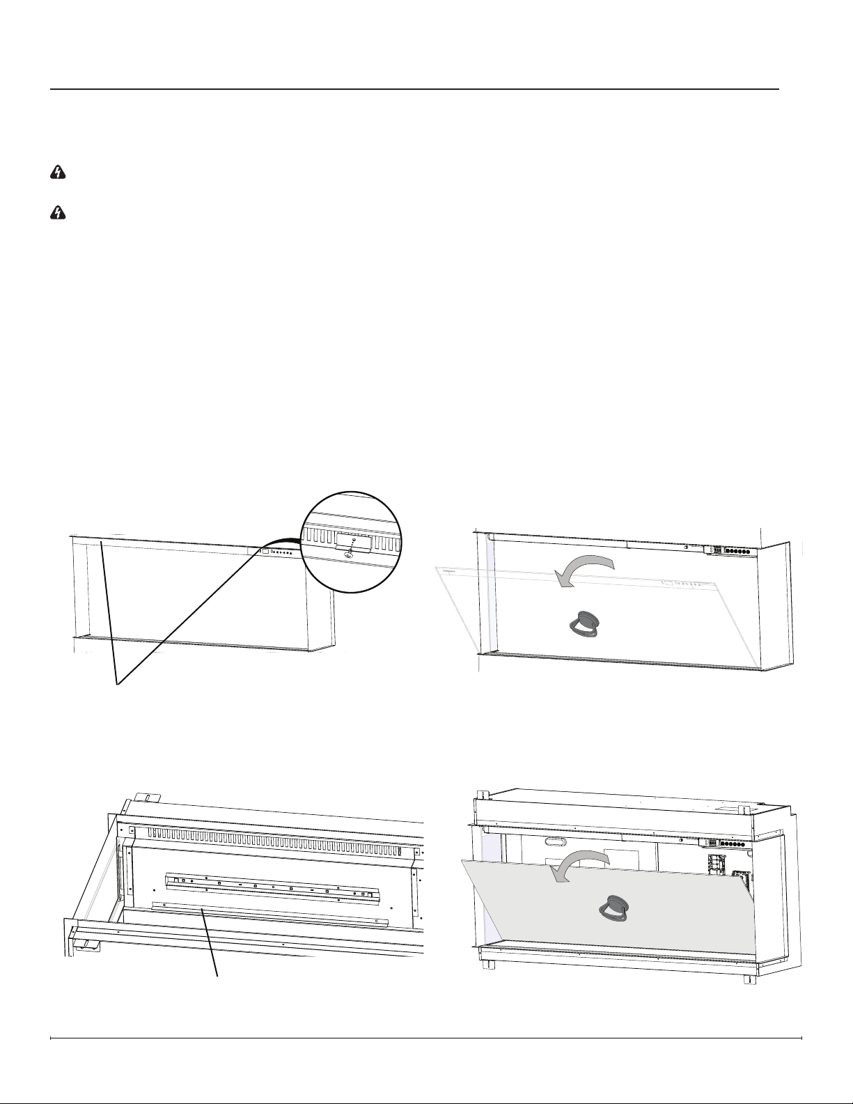
1. Remove front glass bracket(s) (Figure 1).
2. Tilt the front glass outward and lift to remove it (Figure 2). Set it in a safe place for the duration of the service.
3. For corner or bay installations, remove the slide glass by pushing it up and tilting it outward from the bottom.
4. Remove the media and put it aside for the duration of the service.
5. Remove the mirrored glass brackets (Figure 3).
6. Tilt the mirrored glass and lift to remove it (Figure 4).
Front Glass Bracket(s) -
Quantity varies by model
Preparing the Firebox for Service
Figure1
Mirrored Glass Bracket -
Quantity varies by model
Figure2
Figure3
Figure4
11
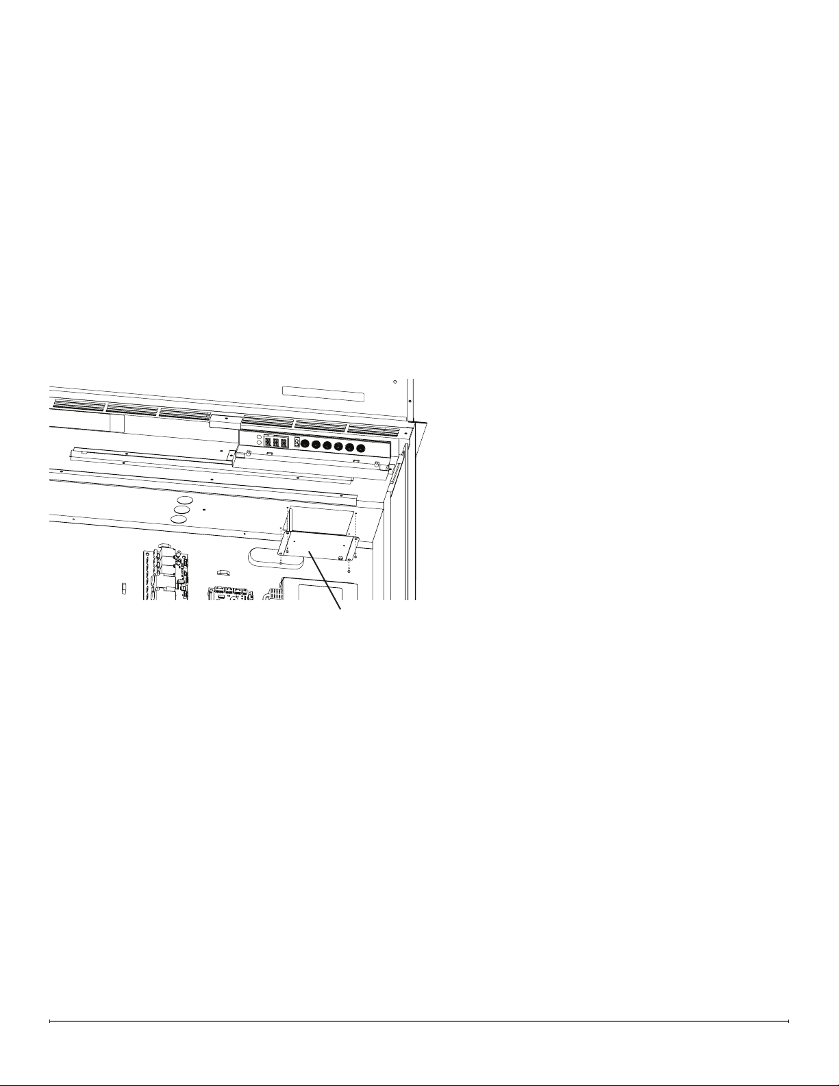
Heater Assembly Replacement
Tools Required: Phillips-Head Screwdriver
Pliers
1. Follow the instructions for Preparing Firebox for Service on page 10.
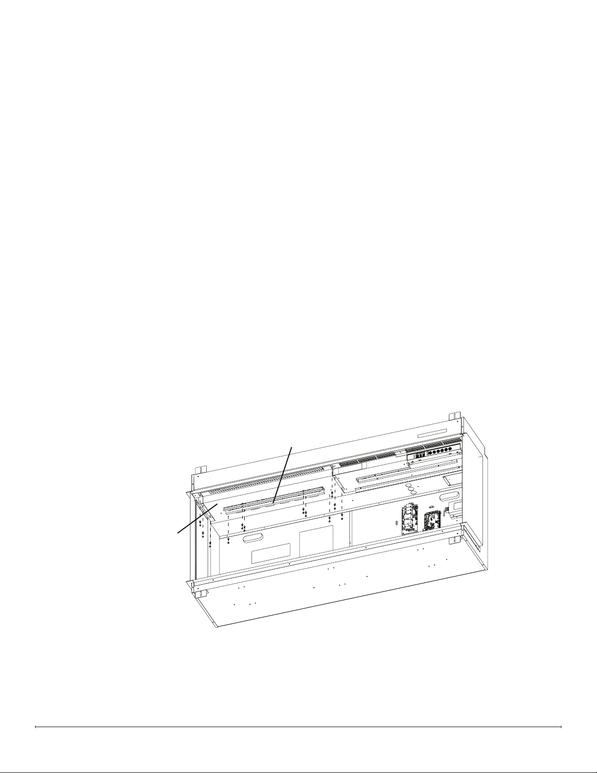
2. Remove the 4 screws that secure the overhead LED assembly. Unplug the LED connection, and set the assembly
aside (Figure 5).
3. Remove the 8 screws around the perimeter of the heater assembly panel (Figure 5).
4. Push the heater assembly toward the back of the replace. It will move about 1/2 inch.
5. Hold the heater assembly front edge and lower the heater assembly.
6. Trace the connections from the heater assembly to the relay board. Carefully disconnect the connections, noting
their original locations. Cut any restrictive wire ties.
7. Remove the defective heater assembly.
8. Feed the wires, one at a time, from the new heater assembly through the top portion of the housing to make the
connections on the relay board.
9. Connect the wires from the heater assembly to the correct locations on the relay board.
10. Secure the wires using the provided wire ties and ensure they are pushed back as to not be too close to the back of
the mirrored glass.
11. Position the new heater assembly by aligning the back of the bracket in the top housing and tilting it upward. Ensure
the LED wire is fed through the slot for the LED assembly
12. Pull the heater assembly forward to align the screw holes. Secure using the previously removed screws.
13. Connect the LED wire, ensuring the IN marking on the board is oriented toward the right side. Secure the LED
assembly.
Heater Assembly
(Includes panel)
Overhead LED
Assembly
Figure5
12 www.dimplex.com
Main Control Board Replacement
Tools Required: Phillips-Head Screwdriver
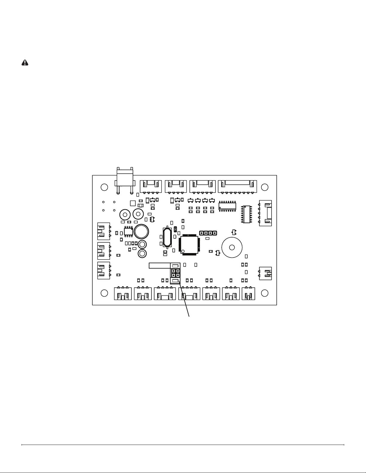
1. Locate the jumper terminal on the new main control board and remove the jumper shown. (Figure 6)
CAUTION: The Heat Disable jumper should only be removed if a permanently heat-disabled installation is required.
See owner’s manual for more information.
2. Follow the instructions for Preparing Firebox for Service on page 10.
3. Remove the screw on each corner of the main control board (4 total) (Figure 7 / Figure 8).
4. Disconnect the wires from the main control board, noting their original locations.
5. Secure the new main control board using the previously removed screws.
6. Connect the wires on the new main control board in the correct locations.
7. Ensure wires are not too close to the mirrored glass.
8. Reassemble the rebox.
Heater Disable
Remove this jumper
Figure 6
13
Tools Required: Phillips-Head Screwdriver
1. Follow the instructions for Preparing Firebox for Service on page 10.
2. Remove the 4 screws that secure the power supply bracket (Figure 7 / Figure 8).
3. Trace the wires from the defective power supply and disconnect the power supply connections from the main
control board and relay board (and adaptor board, for XLF8817-XD and XLF10017-XD models), noting their original
locations. Cut restrictive wire ties.
4. Position the new power supply and secure it using the power supply bracket.
5. Connect the new supply in the correct locations on the main control board and relay board.
6. Replace any wire ties that have been cut. Ensure wires are not too close to the mirrored glass.
7. Reassemble the rebox.
Power Supply Replacement
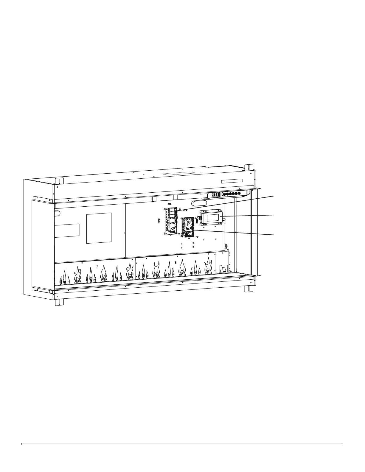
Relay Board
5 Amp Power Supply
Main Control Board
Models XLF5017-XD, XLF6017-XD, and XLF7417-XD ElectronicsFigure 7
14 www.dimplex.com
Relay Board Replacement
Tools Required: Phillips-Head Screwdriver
Pliers
1. Follow the instructions for Preparing Firebox for Service on page 10.
2. Remove the screw on each corner of the relay board (4 total) (Figure 7 / Figure 8).
3. Disconnect the wires from the relay board, noting their original locations.
4. Secure the new relay board using the previously removed screws.
5. Connect the wires on the new relay board in the correct locations.
6. Ensure wires are not too close to the mirrored glass.
7. Reassemble the rebox.
Adapter Board Replacement (XLF8817-XD & XLF10017-XD)
Tools Required: Phillips-Head Screwdriver
1. Follow the instructions for Preparing Firebox for Service on page 10.
2. Remove the screw on each corner of the adapter board (4 total) (Figure 8).
3. Disconnect the wires from the adapter board, noting their original locations.
4. Secure the new adapter board using the previously removed screws.
5. Connect the wires on the new adapter board in the correct locations.
6. Ensure wires are not too close to the mirrored glass.
7. Reassemble the rebox.
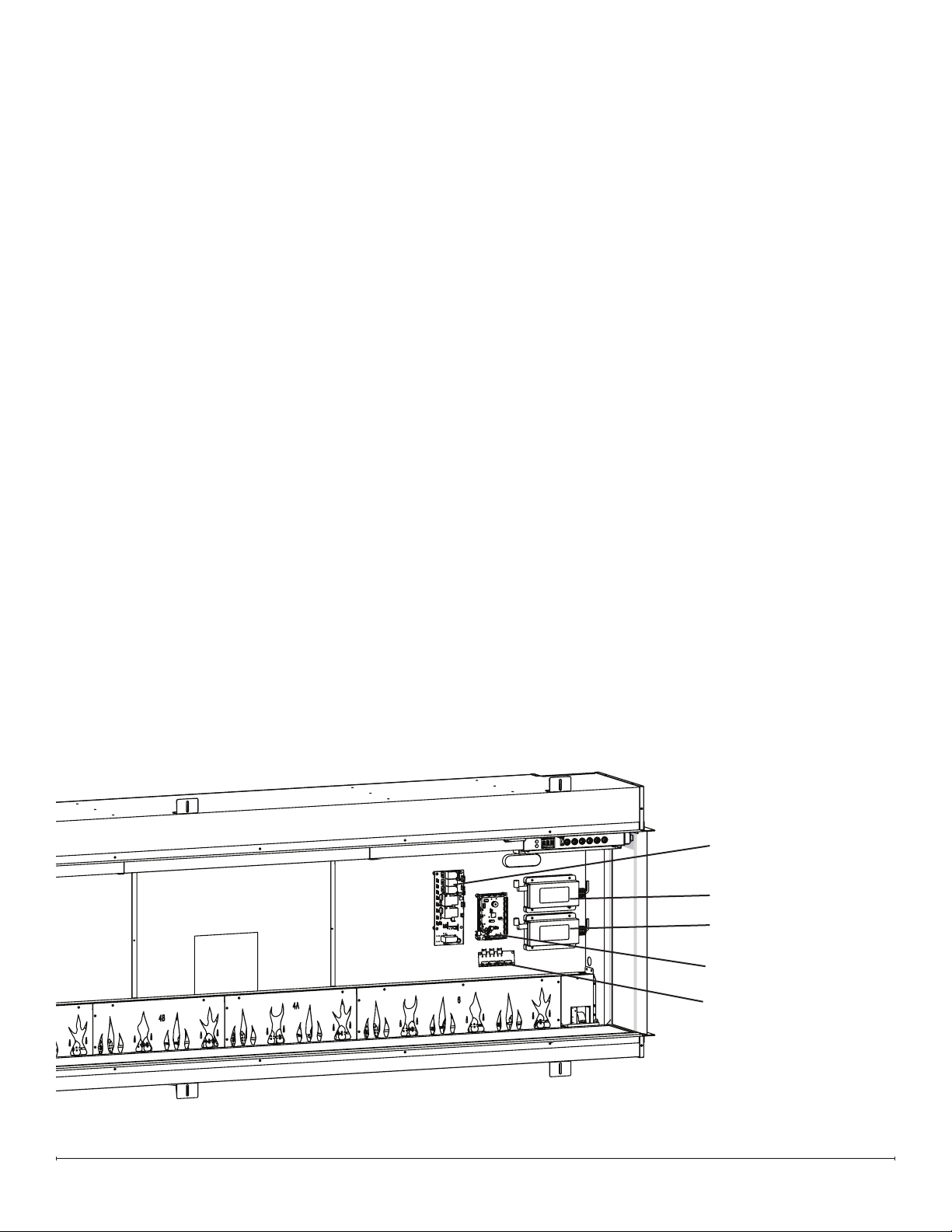
Relay Board
5 Amp Power Supply
3 Amp Power Supply
Main Control Board
Adapter Board
Figure 8 Models XLF8817-XD and XLF10017-XD Electronics
15
Hidden Touch Controls Replacement
Tools Required: Phillips-Head Screwdriver
1. Follow the instructions for Preparing Firebox for Service on page 10.
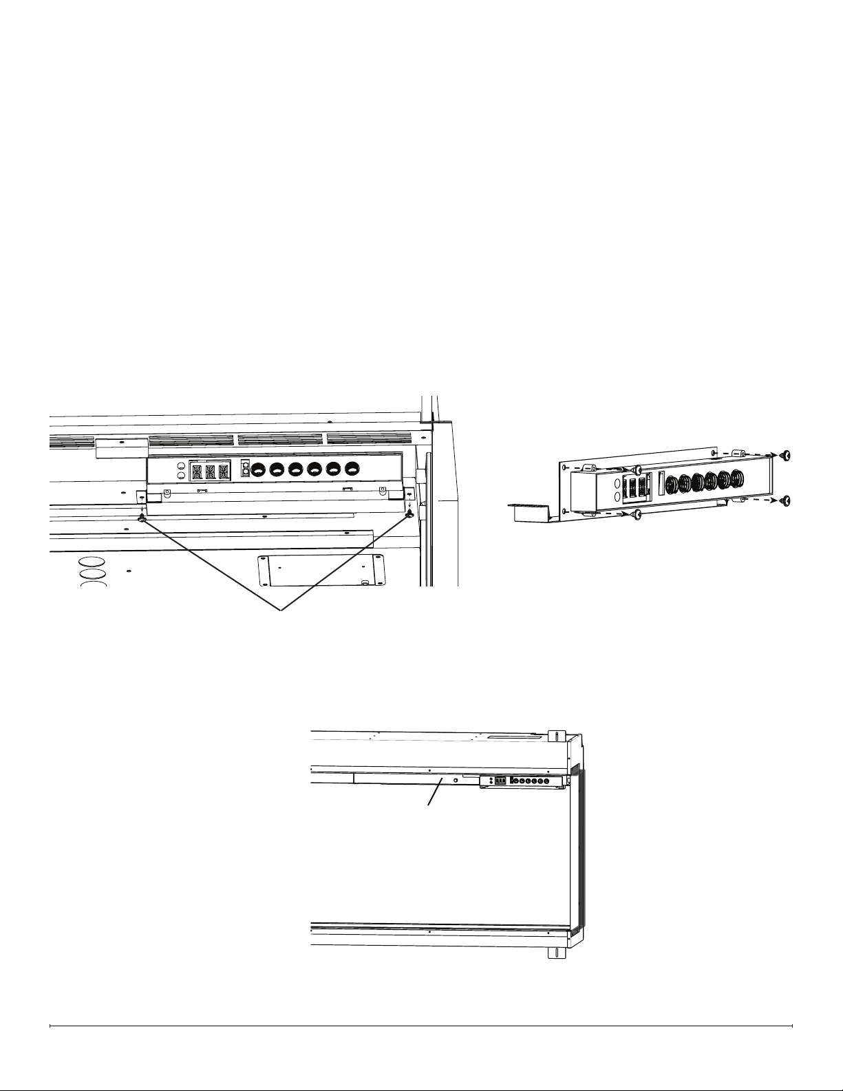
2. Remove the screws on either side of the hidden touch controls bracket (Figure 9).
3. Remove the 4 screws that secure the board to the bracket (Figure 10).
4. Properly orient the new board on the bracket (the connector pins should align with the cutout).
5. Secure the board using the 4 screws previously removed. Do not overtighten.
6. Connect the connector to the board.
7. Secure the bracket on the upper housing.
8. Replace the QR Code labels provided over the existing QR label on the replace and the owner’s manual (Figure 11)
If using the Flame Connect app, you will need to reconnect your replace to the app following replacement of the
hidden touch controls..
9. Reassemble the rebox.
Bracket Screws
Figure 9
Figure 10
QR Code label location
(QR Code label must be
updated when hidden touch
controls are replaced)
Figure 11
16 www.dimplex.com
Temperature Sensor (NTC) Replacement
Tools Required: Phillips-Head Screwdriver
Side Cutters
1. Follow the instructions for Preparing Firebox for Service on page 10.
2. Remove the 4 screws on the NTC bracket (Figure 12).
3. Trace the NTC wire to the mainboard.
4. Disconnect the NTC and remove it, cutting any restrictive wire ties. Make note of the location of the NTC connector.
5. Feed the connector from the new NTC toward the main control board, and connect it into the correct location.
6. Secure the new NTC on the NTC bracket using the provided wire tie.
7. Secure the bracket using the 4 screws previously removed.
8. Reassemble the rebox.
NTC Bracket
Figure 12
17
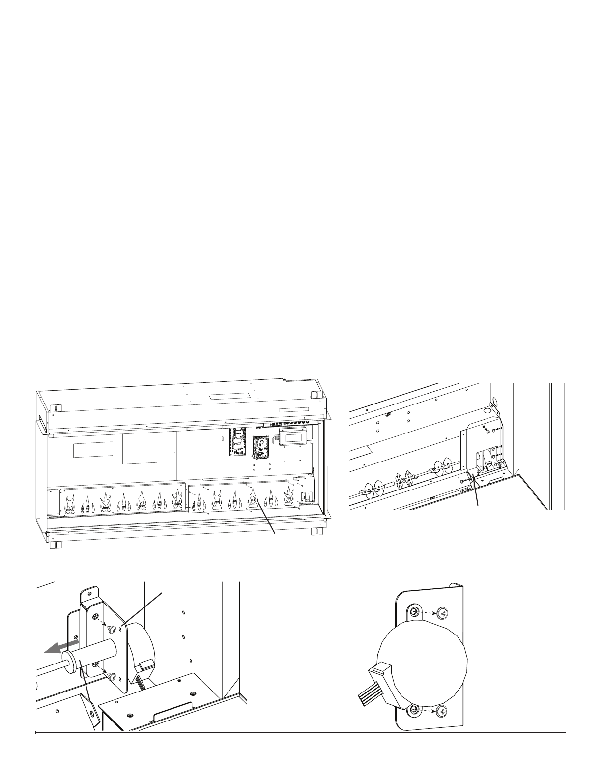
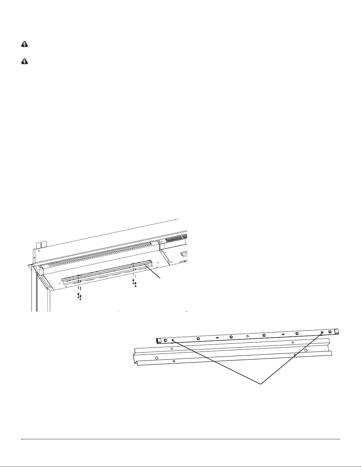
Flicker Motor Replacement
Tools Required: Phillips-Head Screwdriver
1. Follow the instructions for Preparing Firebox for Service on page 10.
2. Remove the 10 screws that secure the ame panel furthest to the right (Figure 13).
3. Remove the 9 screws that secure the icker motor housing (Figure 14).
4. Remove the 2 screws that secure the icker motor bracket to the back panel (Figure 15).
5. Detach the icker rod from the icker motor by carefully exing it and pulling out the rubber sleeve (Figure 15).
6. Remove the 2 screws that secure the icker motor to the icker motor bracket (Figure 16).
7. Trace the wires from the defective icker motor to the main control board.
8. Disconnect the icker motor from the main control board and remove it, cutting any restrictive wire ties.
9. Connect the new icker motor in the correct location on the main control board.
10. Secure the icker motor to the icker motor bracket using the 2 screws previously removed.
11. Secure the icker motor bracket to the back of the rebox, using the 2 screws previously removed.
12. Re-bundle the wires using the provided wire tie.
13. Attach the icker rod to the icker motor.
14. Secure the icker motor housing, using the 9 screws previously removed.
15. Reassemble the rebox.
Remove ame panel Remove ame panel
closest to icker motorclosest to icker motor
Flicker Motor Housing
Flicker Motor BracketFlicker Motor Bracket
Carefully pull out rubber Carefully pull out rubber
sleeve of icker rodsleeve of icker rod
Figure 13
Figure 14
Figure 15
Figure 16
18 www.dimplex.com
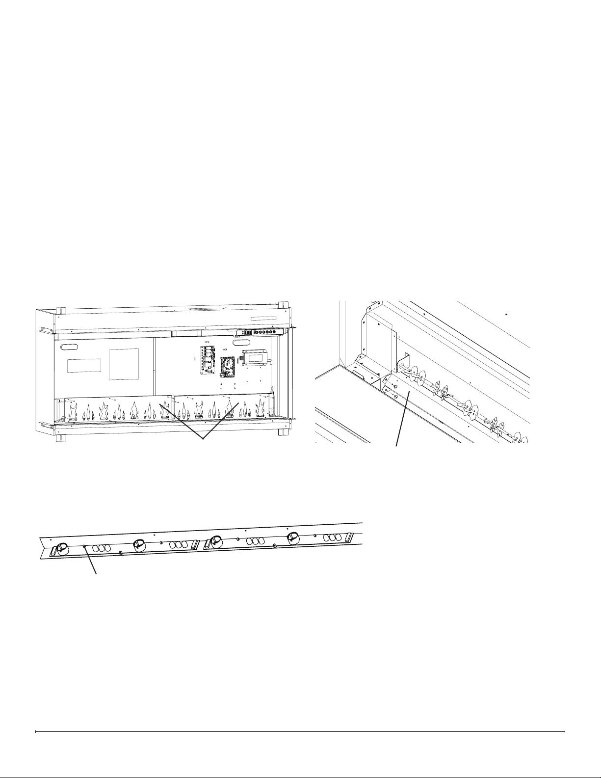
Tools Required: Phillips-Head Screwdriver
Pliers
1. Follow the instructions for Preparing Firebox for Service on page 10.
2. Remove the screws that secure the ame panels (number of screws will vary) (Figure 17). Set the ame panels aside,
making note of their original order as they are removed.
3. Remove the 2 screws on each extremity (4 total) of the ame LED bracket (Figure 18).
4. Pinch each rivet using pliers while gently pulling the LED board off to release it (Figure 19).
5. Position the new ame LED board, and secure it by gently pressing it onto the rivets. Ensure the IN marking on the
board is oriented toward the right side.
6. Secure the ame LED bracket using the 4 screws previously removed.
7. Reinstall the ame panels in the order opposite of which they were removed, ensuring they remain in the correct
order.
8. Reassemble the rebox.
Flame LED Replacement
Flame Panels (quantity
will vary by model)
Flame LED Bracket
Pinch rivets using pliers
to release LED board
Figure 17
Figure 18
Figure 19
19
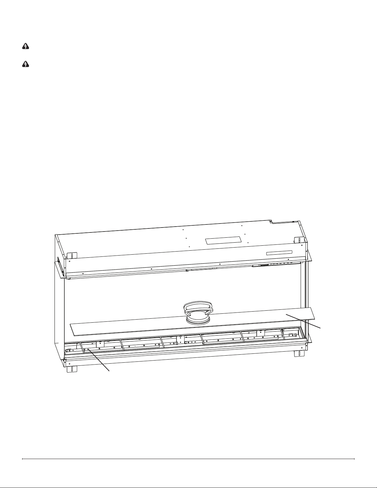
Media Bed LED Replacement
WARNING: If the rebox was operating prior to servicing, allow at least 10 minutes for the heating elements to cool
off to avoid accidental burning of skin.
WARNING: Disconnect power before attempting any maintenance to reduce the risk of electric shock or injury to
persons.
Tools Required: Phillips-Head Screwdriver
Suction Cup (if available)
1. Remove front glass bracket(s) (Figure 1, page 10).
2. Tilt the front glass outward and lift to remove it. Set it in a safe place for the duration of the service (Figure 2, page 10).
3. Remove the media and put it aside for the duration of the service.
4. Remove the media tray using the suction cup, if available (Figure 20).
5. Remove the defective media LED board from the bracket by pinching each rivet using pliers, while gently pulling the
board off to release it (Figure 20).
6. Disconnect the connector from the defective media LED board.
7. Position the new media LED board, and secure it by gently pressing it onto the rivets. Ensure the IN marking on the
board is oriented toward the right side.
8. Reassemble the rebox.
Pinch rivets using pliers to
release LED board
Media bed
Figure 20
20 www.dimplex.com
Overhead LED Replacement
WARNING: If the rebox was operating prior to servicing, allow at least 10 minutes for the heating elements to cool
off to avoid accidental burning of skin.
WARNING: Disconnect power before attempting any maintenance to reduce the risk of electric shock or injury to
persons.
Tools Required: Phillips-Head Screwdriver
Pliers
1. Remove front glass bracket(s) (Figure 1, page 10).
2. Tilt the front glass outward and lift to remove it. Set it in a safe place for the duration of the service (Figure 2, page 10).
3. Remove the 4 screws that secure the overhead LED bracket where the defective overhead LED board is located
(Figure 21).
4. Disconnect the defective overhead LED board
5. Remove the defective overhead LED board from the bracket by pinching each rivet using pliers, while gently pulling
the board off to release it (Figure 22).
6. Position the new overhead LED board, and secure it by gently pressing it onto the rivets. Ensure the IN marking on
the board is oriented toward the right side.
7. Secure the overhead LED bracket using the 4 screws previously removed.
8. Reassemble the rebox.
Pinch rivets using pliers to
release LED board
Overhead LED Bracket
Figure 21
Figure 22
21
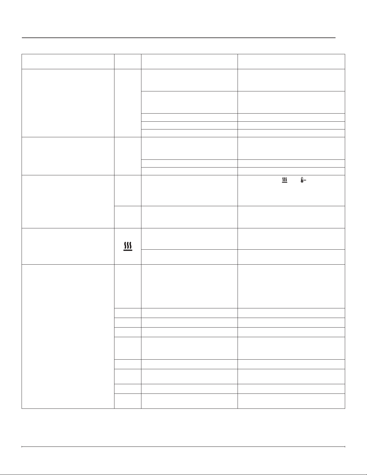
Troubleshooting
Problem Display Cause Solution
Circuit breaker trips or fuse
blows when unit is turned on
N/A Improper circuit current rating
Install unit on a dedicated minimum
15 amp circuit.
Fireplace does not turn on with
the manual touch controls
N/A
No incoming power
Ensure unit is wired correctly
Check main disconnect panel
Ensure wall switch is on (if applicable)
Front glass was installed after unit
was powered on
Turn power off (from breaker or
outlet), install front glass before
turning power back on.
Defective hidden touch controls Replace hidden touch controls
Defective main control board Replace main control board
Defective relay board Replace relay board
Fireplace does not turn on with
the remote control
N/A
The batteries in the remote
control are dead or installed
incorrectly
Replace remote control battery
Ensure battery is installed with +
facing up.
Defective remote control Replace remote control
Defective IR receiver Replace hidden touch controls
Heater does not turn on
---
Heater is disabled
Press and hold
and at the same
time on the hidden touch controls for
3 seconds to disable or enable the
heat function.
H—
Heater has been permanently
disabled
If installation with heat is desired,
jumper on main board if available or
purchase new main board.
Heater is on, but there is no heat
Normal operation — There is a
30-second delay before heater
starts
No action required.
Thermostat setting is below
ambient temperature
Turn up the thermostat setting to be
above ambient temperature
Error Code is displayed
Err 1
Temperature cut-out is activated
Reset breaker and wait 30 minutes
before turning unit back on it.
Ensure heater intakes and exhausts
are not obstructed. Clean with
compressed air if necessary.
Defective heater assembly.
Err 2
L1 voltage is too high If error persists, consult an electrician.
Err 3
L1 voltage is too low If error persists, consult an electrician.
Err 4
L1 current is too high If error persists, consult an electrician.
Err 5
Fan not detected
Fan wire is disconnected.
Defective heater assembly.
Defective relay board.
Err 6
Fan error Defective heater assembly.
Err 7
Fan is slow
Clean fan.
Defective heater assembly.
Err 8
Element error Defective heater assembly.
Err 9
Element not detected
Element wire(s) is/are disconnected.
Defective heater assembly.
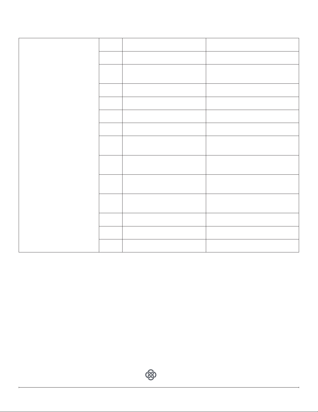
22 www.dimplex.com
Error Code is displayed
Err12
Ambient temperature is
above45°C (113° F)
No action required.
Err13
Ambient temperature is
below45°C (113° F)
No action required.
Err14
NTC error
NTC is unplugged.
NTC is defective.
Main Control Board is defective.
Err15
NTC has shorted
NTC is unplugged.
NTC is defective.
Err16
NTC not detected
NTC is unplugged.
NTC is defective.
Err17
Media bed LEDs defective
Defective Media Bed LEDs.
Defective Main Control Board
Err18
Overhead LEDs defective
Defective Overhead LEDs.
Defective Main Control Board
Err19
Media bed LEDs not detected
Media Bed LEDs disconnected.
Defective Media Bed LEDs.
Defective Main Control Board
Err 20
Overhead LEDs not detected
Overhead LEDs disconnected.
Defective Overhead LEDs.
Defective Main Control Board
Err 21
Flame LEDs not detected
Flame LEDs disconnected.
Defective Flame LEDs.
Defective Main Control Board
Err 22
Flicker motor not detected
Flicker motor is disconnected.
Defective Flicker motor.
Defective Main control board.
Err 23
Relay board not detected
Relay board is disconnected.
Defective Relay board.
Err 24
Main control board not detected
Main control board is disconected.
Defective Main control board.
Err 25
Display board not detected
Defective Display board.
Defective Main control board.
1-888-346-7539 | www.dimplex.com
In keeping with our policy of continuous
product improvement, we reserve the
right to make changes without notice.
© 2022 Glen Dimplex Americas
A BRAND OF GLEN DIMPLEX AMERICAS
REV ECO DATE
00 ECO-000201 13-APR-21
01 ECO-000208 28-MAY-21
03 ECO-000436 24-MAY-22
App
For troubleshooting information related to the Flame Connect app, please visit www.dimplex.com/fcapp