
User Manual
Gigabit Ethernet Plus Switches
Models
GS105Ev2
GS105PE
GS108Ev3
GS108PEv3
GS116Ev2
GS305E
GS308E
JGS516PE
JGS524Ev2
JGS524PE
NETGEAR, Inc.
350 E. Plumeria DriveMay 2022
San Jose, CA 95134, USA202-11700-06

Support and Community
Visit netgear.com/support to get your questions answered and access the latest
downloads.
You can also check out our NETGEAR Community for helpful advice at
community.netgear.com.
Regulatory and Legal
Si ce produit est vendu au Canada, vous pouvez accéder à ce document en français
canadien à https://www.netgear.com/support/download/.
(If this product is sold in Canada, you can access this document in Canadian French at
https://www.netgear.com/support/download/.)
For regulatory compliance information including the EU Declaration of Conformity, visit
https://www.netgear.com/about/regulatory/.
See the regulatory compliance document before connecting the power supply.
For NETGEAR’s Privacy Policy, visit https://www.netgear.com/about/privacy-policy.
By using this device, you are agreeing to NETGEAR’s Terms and Conditions at
https://www.netgear.com/about/terms-and-conditions. If you do not agree, return the
device to your place of purchase within your return period.
Do not use this device outdoors.
Trademarks
© NETGEAR, Inc., NETGEAR, and the NETGEAR Logo are trademarks of NETGEAR, Inc.
Any non-NETGEAR trademarks are used for reference purposes only.
2
Gigabit Ethernet Plus Switches

Revision History
CommentsPublish DatePublication Part
Number
Changed the name of the manual from Gigabit Ethernet Smart Managed Plus
Switches User Manual to Gigabit Ethernet Plus Switches User Manual.
Added Related documentation on page 8.
Added Assign a fixed IP address to the switch on page 21 and subsections.
Revised VLAN overview on page 29.
Added About Quality of Service on page 41.
Revised Manage flow control on page 57.
Revised Manage the port speed and the port status on page 58.
Revised Change the switch password on page 70.
Revised multiple specifications in Technical specifications on page 80.
Renamed local browser interface to device user interface (UI).
Made multiple minor changes.
Removed information about the ProSAFE Plus utility and NETGEAR Insight app.
May 2022202-11700-06
Added new models GS305E and GS308E
Added the chapter Hardware on page 7 and information about status LEDs
for each model in Status LEDs on page 9.
Added technical specifications for each model in Technical specifications on
page 80.
February 2019202-11700-05
Added a note to Manage access control on page 66 to state that models
GS108Ev3 and GS108PEv3 do not support access control.
October 2018202-11700-04
Changed the manual name from ProSAFE Gigabit Web Managed (Plus) Switches
User Manual to Gigabit Ethernet Smart Managed Plus Switches User Manual.
Added Safety instructions and warnings on page 12.
Revised About configuring the switch on page 17.
Revised Access a switch that is connected to a network on page 18.
Added Use the NETGEAR Switch Discovery Tool to access the switch on page
20.
Added Change the language on page 24, including Change the language for
the device UI on page 24 and Change the language for the device UI by installing
another firmware version on page 25.
Added Manage access control on page 66 including Add devices to the Access
Control list on page 66 and Remove devices from the Access Control list on
page 67.
Added PoE considerations for switches that support PoE on page 72.
Added PoE troubleshooting suggestions on page 76.
Removed references to the resource CD.
Made multiple minor changes.
October 2018202-11700-03
Made corrections to Advanced 802.1Q-based VLANs: Specify a port PVID on
page 38.
March 2017202-11700-02
First publication.August 2016202-11700-01
3
Gigabit Ethernet Plus Switches

Contents
Chapter 1 Hardware
Related documentation.......................................................................8
Supported switch models....................................................................8
Status LEDs............................................................................................9
Models GS105Ev2, GS108Ev3, GS116Ev2, GS305E, and GS308E
LEDs...................................................................................................9
Model GS105PE LEDs......................................................................9
Model GS108PEv3 LEDs...............................................................10
Model JGS524Ev2 LEDs................................................................11
Models JGS516PE and JGS524PE LEDs.....................................11
Safety instructions and warnings......................................................12
Chapter 2 Get Started
About configuring the switch............................................................17
Access the switch using a web browser..........................................17
Access a switch that is connected to a network.........................18
Access a switch that is off-network..............................................19
Use the NETGEAR Switch Discovery Tool to access the switch....20
Assign a fixed IP address to the switch............................................21
Set a fixed IP address for the switch through a network
connection......................................................................................22
Assign a fixed IP address by connecting directly to the switch
off-network......................................................................................23
Change the language........................................................................24
Change the language for the device UI......................................24
Change the language for the device UI by installing another
firmware version.............................................................................25
Register the switch..............................................................................26
Chapter 3 Use VLANS for Traffic Segmentation
VLAN overview....................................................................................29
Basic port-based VLANs: Assign ports to VLANs...........................30
Advanced port-based VLANs: Assign ports to multiple VLANs....31
Basic 802.1Q-based VLANs: Assign ports to VLANs.....................34
Advanced 802.1Q-based VLANs: Create VLANs...........................35
4

Advanced 802.1Q-based VLANs: Add tagged or untagged
ports.....................................................................................................37
Advanced 802.1Q-based VLANs: Specify a port PVID..................38
Chapter 4 Optimize Performance With Quality of Service
About Quality of Service....................................................................41
Set port-based QoS and set the priority level for one or more
ports.....................................................................................................41
Set 802.1p/DSCP-based QoS for all ports......................................43
Set up rate limiting.............................................................................44
Set up broadcast filtering..................................................................46
Chapter 5 Manage Network Settings
Specify IP address settings for the switch........................................49
Change the switch IP address......................................................49
Manage multicast traffic with IGMP snooping................................50
Customize IGMP snooping...........................................................51
Specify a VLAN for IGMP snooping.............................................52
Set up link aggregation groups........................................................53
Chapter 6 Manage and Monitor the Switch
Manage flow control..........................................................................57
Manage the port speed and the port status...................................58
Enable loop detection.......................................................................59
Manage power saving options.........................................................60
Download and update the firmware................................................61
Reboot the switch...............................................................................63
Save the switch configuration...........................................................63
Restore a saved switch configuration..............................................64
Restore factory default settings........................................................65
Manage access control......................................................................66
Add devices to the Access Control list........................................66
Remove devices from the Access Control list............................67
Enable port mirroring........................................................................68
View switch information or change the switch device name........69
Change the switch password............................................................70
View or clear the port statistics.........................................................71
PoE considerations for switches that support PoE.........................72
Chapter 7 Diagnostics and Troubleshooting
Test cable connections......................................................................75
Resolve a subnet conflict to access the switch................................76
PoE troubleshooting suggestions....................................................76
5
Gigabit Ethernet Plus Switches

Appendix A Factory Default Settings and Technical Specifications
Factory default settings......................................................................79
Technical specifications.....................................................................80
Model GS105Ev2 technical specifications..................................80
Model GS105PE technical specifications....................................80
Model GS108Ev3 technical specifications..................................81
Model GS108PEv3 technical specifications................................82
Model GS116Ev2 technical specifications..................................83
Model GS305E technical specifications......................................83
Model GS305EP and GS308EP technical specifications...........84
Model GS305EPP and GS308EPP technical specifications......85
Model GS308E technical specifications......................................85
Models JGS516PE and JGS524PE technical specifications.....86
Model JGS524Ev2 technical specifications................................87
6
Gigabit Ethernet Plus Switches

1
Hardware
This user manual is for the NETGEAR Gigabit Ethernet Plus Switches.
For a list of switch models that are supported by this manual, see Supported switch
models on page 8.
This chapter covers the following topics:
• Related documentation
• Supported switch models
• Status LEDs
• Safety instructions and warnings
Note:
•
This user manual complements the installation guide that came with your switch.
You can also download the installation guide by visiting
netgear.com/support/download/.
•
For more information about the topics covered in this manual, visit the support
website at netgear.com/support
•
Firmware updates with new features and bug fixes are made available from time to
time at netgear.com/support/download/. You can check for and download new
firmware manually. If the features or behavior of your product does not match what
is described in this guide, see the latest firmware release notes for your switch model.
7

Related documentation
The following related documentation is available at netgear.com/support/download/:
•
Installation guide
•
Data sheet
Supported switch models
The Gigabit Ethernet Plus Switches User Manual describes the switch models that are
listed in the following table.
Table 1. Supported switch models
NameModel
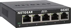
5-Port Gigabit Ethernet Plus SwitchGS105Ev2
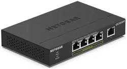
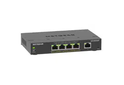
5-Port Gigabit Ethernet PD-Powered/PoE Pass-thru Plus SwitchGS105PE
8-Port Gigabit Ethernet Plus SwitchGS108Ev3
8-Port Gigabit Ethernet Plus Switch with 4-Ports PoEGS108PEv3
16-Port Gigabit Ethernet Plus SwitchGS116Ev2
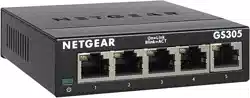
5-Port Gigabit Ethernet Plus SOHO SwitchGS305E
8-Port Gigabit Ethernet Plus SOHO SwitchGS308E
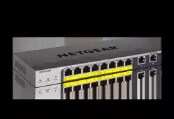
16-Port Gigabit Ethernet Plus Switch with 8 Ports PoEJGS516PE
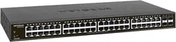
24-Port Gigabit Ethernet Plus SwitchJGS524Ev2
24-Port Gigabit Ethernet Plus Switch with 12 Ports PoEJGS524PE
User Manual8Hardware
Gigabit Ethernet Plus Switches

Status LEDs
This section describes the status LEDs for each switch model.
For information about the front panel and ports for your switch model, see the installation
guide for you model, which you can download by visiting
netgear.com/support/download/.
Models GS105Ev2, GS108Ev3, GS116Ev2, GS305E, and
GS308E LEDs
This section describes the LED designations of models GS105Ev2, GS108Ev3, GS116Ev2,
GS305E, and GS308E.
Table 2. Model GS105Ev2, GS108Ev3, GS116Ev2, GS305E, and GS308E LEDs on the front panel
DescriptionLEDs
The switch is powered on and operating normally.Solid greenPower LED
Power is not supplied to the switch.Off
Combined, these RJ-45 port LEDs indicate link, speed, and activity.Right port LEDsLeft port LEDs
A valid 1 Gbps port link is established.Solid greenSolid green
The port is transmitting or receiving packets at 1 Gbps.Blinking greenBlinking green
A valid 100 Mbps port link is established.OffSolid green
The port is transmitting or receiving packets 100 Mbps.OffBlinking green
A valid 10 Mbps port link is established.Solid greenOff
The port is transmitting or receiving packets 10 Mbps.Blinking greenOff
No port link is established.OffOff
Model GS105PE LEDs
This section describes the LED designations of model GS105PE.
Ports 1 and 2 are PoE ports that can deliver PoE. Ports 3 and 4 are regular Ethernet
ports. Port 5 is a PoE PD port that must receive power from a PoE switch.
User Manual9Hardware
Gigabit Ethernet Plus Switches

Table 3. Model GS105PE LEDs on the front panel
DescriptionLED
Solid green. The switch is powered on, is operating normally, and PoE pass-through
is enabled.
Blinking green. PoE pass-through is disabled.
Off. Power is not supplied to the switch.
Power LED
Solid green. A valid 1 Gbps port link is established.
Blinking green. The port is transmitting or receiving packets at 1 Gbps.
Solid yellow. A valid 10 Mbps or 100 Mbps port link is established.
Blinking yellow. The port is transmitting or receiving packets at 10 Mbps or
100 Mbps.
Off. No port link is established.
Left LEDs (link, speed, and
activity) for all ports
Off. The port is not delivering PoE power.
Solid green. The port is delivering PoE power.
Blinking green. A PoE fault occurred.
Right LEDs for PoE PSD ports
1 and 2
Off. The port is not receiving PoE power.
Solid green. The port is receiving PoE+ (802.3at) power from a PSE.
Solid yellow. The port is receiving PoE (802.3af) power from a PSE.
Right LED for PoE PD port 5
Model GS108PEv3 LEDs
This section describes the LED designations of model GS108PEv3.
Ports 1 through 4 are PoE ports. Ports 5 through 8 are regular Ethernet ports.
Table 4. Model GS108PEv3 LEDs on the front panel
DescriptionLED
Solid green. The switch is powered on and operating normally.
Off. Power is not supplied to the switch.
Power LED
Off. Sufficient (more than 7W of) PoE power is available.
Solid yellow. Less than 7W of PoE power is available.
Blinking yellow. At least once during the previous two minutes, less than 7W of PoE
power was available.
PoE Max LED
User Manual10Hardware
Gigabit Ethernet Plus Switches

Table 4. Model GS108PEv3 LEDs on the front panel (Continued)
DescriptionLED
Solid green. A valid 1 Gbps port link is established.
Blinking green. The port is transmitting or receiving packets at 1 Gbps.
Solid yellow. A valid 10 Mbps or 100 Mbps port link is established.
Blinking yellow. The port is transmitting or receiving packets at 10 Mbps or
100 Mbps.
Off. No port link is established.
Port link, speed, and activity
LEDs for all ports
Off. The port is not delivering PoE power.
Solid green. The port is delivering PoE power.
Solid yellow. A PoE fault occurred.
Port PoE status LEDs for PoE
ports only
Model JGS524Ev2 LEDs
This section describes the LED designations of model JGS524Ev2. The port LEDs are
located to the left of the ports, that is, not above or below the ports.
Table 5. Model JGS524Ev2 LEDs on the front panel
DescriptionLEDs
Solid green. The switch is powered on and operating normally.
Off. Power is not supplied to the switch.
Power LED
Solid green. A valid 1 Gbps port link is established.
Solid yellow. A valid 100 Mbps port link is established.
Off. A valid 10 Mbps port link is established.
Port speed LEDs
Blinking green. The port is transmitting or receiving packets.
Off. No port link is established.
Port Link/ACT LEDs
Models JGS516PE and JGS524PE LEDs
This section describes the LED designations of models JGS516PE and JGS524PE. The
port LEDs are located to the left of the ports, that is, not above or below the ports.
On model JGS516PE, ports 1 through 8 are PoE ports. Ports 9 through 16 are regular
Ethernet ports.
On model JGS524PE, ports 1 though 12 are PoE ports. Ports 13 through 24 are regular
Ethernet ports.
User Manual11Hardware
Gigabit Ethernet Plus Switches

Table 6. Model JGS516PE and JGS524PE LEDs on the front panel
DescriptionLED
Solid green. The switch is powered on and operating normally.
Off. Power is not supplied to the switch.
Power LED
Off. The fan is operating normally.
Solid yellow. A problem occurred with the fan.
Fan LED
Off. Sufficient (more than 7W of) PoE power is available.
Solid yellow. Less than 7W of PoE power is available.
Blinking yellow. At least once during the previous two minutes, less than 7W of PoE
power was available.
PoE Max LED
Solid green. A valid 1 Gbps port link is established.
Blinking green. The port is transmitting or receiving packets at 1 Gbps.
Solid yellow. A valid 10 Mbps or 100 Mbps port link is established.
Blinking yellow. The port is transmitting or receiving packets at 10 Mbps or
100 Mbps.
Off. No port link is established.
Port link, speed, and activity
LEDs for all ports
Off. The port is not delivering PoE power.
Solid green. The port is delivering PoE power.
Solid yellow. A PoE fault occurred.
Port PoE status LEDs for PoE
ports only
Safety instructions and warnings
Use the following safety guidelines to ensure your own personal safety and to help
protect your system from potential damage.
To reduce the risk of bodily injury, electrical shock, fire, and damage to the equipment,
observe the following precautions:
•
This product is designed for indoor use only in a temperature-controlled and
humidity-controlled environment.
Note the following:
-
For more information about the environment in which this product must operate,
see the environmental specifications in the appendix or the data sheet.
-
If you want to connect the product to a device located outdoors, the outdoor
device must be properly grounded and surge protected, and you must install an
Ethernet surge protector inline between the indoor product and the outdoor
device. Failure to do so can damage the product.
WARNING: Before connecting the product to outdoor cables or devices, see
https://kb.netgear.com/000057103 for additional safety and warranty information.
User Manual12Hardware
Gigabit Ethernet Plus Switches

Failure to follow these guidelines can result in damage to your NETGEAR product,
which might not be covered by NETGEAR’s warranty, to the extent permissible by
applicable law.
•
Observe and follow service markings:
- Do not service any product except as explained in your product documentation.
Some devices should never be opened.
-
If applicable to your product, opening or removing covers that are marked with
the triangular symbol with a lightning bolt can expose you to electrical shock.
We recommend that only a trained technician services components inside these
compartments.
•
If any of the following conditions occur, unplug the product from the power outlet,
and then replace the part or contact your trained service provider:
- Depending on your product, the power adapter, power adapter cable, power
cable, extension cable, or plug is damaged.
-
An object fell into the product.
- The product was exposed to water.
- The product was dropped or damaged.
-
The product does not operate correctly when you follow the operating
instructions.
•
Keep the product away from radiators and heat sources. Also, do not block cooling
vents.
•
Do not spill food or liquids on your product components, and never operate the
product in a wet environment. If the product gets wet, see the appropriate section
in your troubleshooting guide, or contact your trained service provider.
•
Do not push any objects into the openings of your product. Doing so can cause fire
or electric shock by shorting out interior components.
•
Use the product only with approved equipment.
•
If applicable to your product, allow the product to cool before removing covers or
touching internal components.
•
Operate the product only from the type of external power source indicated on the
electrical ratings label. If you are not sure of the type of power source required,
consult your service provider or local power company.
User Manual13Hardware
Gigabit Ethernet Plus Switches

•
To avoid damaging your system, if your product uses a power supply with a voltage
selector, be sure that the selector is set to match the power at your location:
-
115V, 60 Hz in most of North and South America and some Far Eastern countries
such as South Korea and Taiwan
- 100V, 50 Hz in eastern Japan and 100V, 60 Hz in western Japan
-
230V, 50 Hz in most of Europe, the Middle East, and the Far East
•
Be sure that attached devices are electrically rated to operate with the power available
in your location.
•
Depending on your product, use only a supplied power adapter or approved power
cable:
If your product uses a power adapter:
-
If you were not provided with a power adapter, contact your local NETGEAR
reseller.
-
The power adapter must be rated for the product and for the voltage and current
marked on the product electrical ratings label.
If your product uses a power cable:
-
If you were not provided with a power cable for your system or for any
AC-powered option intended for your system, purchase a power cable approved
for your country.
-
The power cable must be rated for the product and for the voltage and current
marked on the product electrical ratings label. The voltage and current rating of
the cable must be greater than the ratings marked on the product.
•
To help prevent electric shock, plug the system and peripheral power cables into
properly grounded power outlets.
•
If applicable to your product, the peripheral power cables are equipped with
three-prong plugs to help ensure proper grounding. Do not use adapter plugs or
remove the grounding prong from a cable. If you must use an extension cable, use
a three-wire cable with properly grounded plugs.
•
Observe extension cable and power strip ratings. Make sure that the total ampere
rating of all products plugged into the extension cable or power strip does not
exceed 80 percent of the ampere ratings limit for the extension cable or power strip.
•
To help protect your system from sudden, transient increases and decreases in
electrical power, use a surge suppressor, line conditioner, or uninterruptible power
supply (UPS).
User Manual14Hardware
Gigabit Ethernet Plus Switches

•
Position system cables, power adapter cables, or power cables carefully. Route
cables so that they cannot be stepped on or tripped over. Be sure that nothing rests
on any cables.
•
Do not modify power adapters, power adapter cables, power cables or plugs. Consult
a licensed electrician or your power company for site modifications.
•
Always follow your local and national wiring rules.
User Manual15Hardware
Gigabit Ethernet Plus Switches

2
Get Started
This chapter describes how you can access the switch in your network, change the switch
password, change the language, and register your product.
The chapter covers the following topics:
• About configuring the switch
• Access the switch using a web browser
• Use the NETGEAR Switch Discovery Tool to access the switch
• Assign a fixed IP address to the switch
• Change the language
• Register the switch
16

About configuring the switch
Gigabit Ethernet Plus Switches are plug-and-play, so they can be used without any
configuration. Just connect power, connect to your network and to your other devices,
and you’re done.
For easiest access, we recommend that you cable the switch to a network with a router
or DHCP server that assigns IP addresses and power on the switch. However, it is also
possible to configure the switch connected directly only to the computer that you are
using to configure it, and not connected to the network (off-network).
You can configure and manage advanced features of the switch by using your computer’s
web browser and accessing the switch at its IP address.
If you use a Mac or a 64-bit Windows-based computer, you can use the NETGEAR Switch
Discovery Tool to discover the switch in your network and access the device user interface
(UI) of the switch.
For more information, see the following sections:
•
Access the switch using a web browser on page 17
•
Use the NETGEAR Switch Discovery Tool to access the switch on page 20
•
Assign a fixed IP address to the switch on page 21
Access the switch using a web browser
This manual describes how to use the device user interface, referred to as the device
UI.
You can access and configure the switch directly through its device UI by entering the
IP address of the switch in the address bar of a browser.
When you access the device UI to configure the switch, you can configure the switch
with it connected to your network, router, or modem, (on-network) but you must
determine the IP address that is assigned to the switch. (By default, the switch is a DHCP
client.)
You can also configure the switch not connected to your network (off-network) using
its default IP address. In that case, you must temporarily set the computer that you are
using to configure the switch to a static IP address in the same subnet as the default IP
address of the switch.
User Manual17Get Started
Gigabit Ethernet Plus Switches

Access a switch that is connected to a network
By default, the DHCP client of the switch is enabled. To access the switch, use the IP
address that the DHCP server assigned to the switch.
To determine the IP address of the switch, do one of the following:
•
If you use a Mac or a 64-bit Windows-based computer, use the NETGEAR Switch
Discovery Tool to detect the IP address (see Use the NETGEAR Switch Discovery
Tool to access the switch on page 20).
•
Access the DHCP server.
•
Use an IP scanner utility.
To use your web browser to configure a switch that is connected to a network:
1. Cable the switch to a network with a router or DHCP server that manages IP
addresses.
2. Power on the switch.
The DHCP server assigns the switch an IP address.
3. Connect your computer to the same network as the switch.
4.
Determine the IP address of the switch.
By default, the DHCP client of the switch is enabled. Use the IP address that the
DHCP server assigned to the switch.
5.
Open a web browser, and enter the IP address of the switch.
The login window opens.
6. Enter the switch password.
The default password is password. The password is case-sensitive. The first time
that you log in to the switch, you must change the default password.
7. Click the Login button.
You can now configure additional options for the switch through the device UI.
For information about setting up a fixed (static) IP address for the switch, see Specify
IP address settings for the switch on page 49.
User Manual18Get Started
Gigabit Ethernet Plus Switches

Access a switch that is off-network
To use your web browser to configure a switch that is not connected to a network:
1.
Record your computer’s TCP/IP configuration settings, and then configure the
computer with a static IP address of 192.168.0.210 and 255.255.255.0 as the subnet
mask.
Note: If you are unsure how to do this, visit the support website at
netgear.com/support and search for Static IP address on computer.
2. Plug the switch into a power outlet and then connect your computer to the switch
using an Ethernet cable.
You can connect the Ethernet cable to any port on the switch.
3.
Open a web browser, and enter http://192.168.0.239.
This is the default address of the switch.
The login window opens.
4. Enter the switch password.
The default password is password. The password is case-sensitive. The first time
that you log in to the switch, you must change the default password.
The Switch Information page displays.
5. Click the Login button.
You can now configure additional options for the switch through the device UI.
For information about setting up a fixed (static) IP address for the switch, see Specify
IP address settings for the switch on page 49.
6.
After you complete the configuration of the switch, reconfigure the computer that
you used for this process to its original TCP/IP settings.
You can now connect your switch to your network using an Ethernet cable.
User Manual19Get Started
Gigabit Ethernet Plus Switches

Use the NETGEAR Switch Discovery Tool to
access the switch
For easiest access, we recommend that you cable the switch to a network with a router
or DHCP server that assigns IP addresses, power on the switch, and then use a computer
that is connected to the same network as the switch.
Depending on your model switch, the NETGEAR Switch Discovery Tool lets you discover
the switch in your network and access the device UI of the switch from a Mac or a
Windows-based computer.
To install the NETGEAR Switch Discovery Tool, discover the switch in your network,
and access the device UI of the switch:
1. Download the Switch Discovery Tool by visiting
netgear.com/support/product/netgear-switch-discovery-tool.aspx.
Depending on the computer that you are using, download either the Mac version
or the version for a 64-bit Windows-based computer.
2.
Temporarily disable the firewall, Internet security, antivirus programs, or all of these
on the computer that you use to configure the switch.
3.
Unzip the Switch Discovery Tool files, double-click the .exe or .dmg file (for example,
NETGEAR+Switch+Discovery+Tool+Setup+1.2.101.exe or
NetgearSDT-V1.2.101.dmg), and install the program on your computer.
The installation process places a NETGEAR Switch Discovery Tool icon on your
desktop.
4. Reenable the security services on your computer.
5. Power on the switch.
The DHCP server assigns the switch an IP address.
6. Connect your computer to the same network as the switch.
You can use a WiFi or wired connection. The computer and the switch must be on
the same Layer 2 network.
7. Open the Switch Discovery Tool.
To open the program, double-click the NETGEAR Switch Discovery Tool icon on
your desktop.
The initial page displays a menu and a button.
8. From the Choose a connection menu, select the network connection that allows
the Switch Discovery Tool to access the switch.
User Manual20Get Started
Gigabit Ethernet Plus Switches

9. Click the Start Searching button.
The Switch Discovery Tool displays a list of NETGEAR switches that it discovers on
the selected network.
For each switch, the tool displays the IP address.
10.
To access the device UI of the switch, click the ADMIN PAGE button.
The login window opens.
11. Enter the switch password.
The default password is password. The password is case-sensitive. The first time
that you log in to the switch, you must change the default password.
The Switch Information page displays.
Assign a fixed IP address to the switch
By default, the switch is configured to automatically receive an IP address from a DHCP
server (or a router that functions as a DHCP server) in your network. However, certain
events can cause the DHCP server to issue a new IP address to the switch, so if you need
the switch to persistently have the same IP address, you can assign a fixed (static) IP
address to the switch. For example, you may want to attach a shared device such as a
printer or file server, configure port forwarding, or set up the switch so you can connect
remotely from a mobile device.
To change the IP address of the switch, use one of the following methods:
•
Connect to the switch through the network: If the switch and your computer are
connected to the same network, you can change the IP address of the switch through
a network connection (see Set a fixed IP address for the switch through a network
connection on page 22).
•
Connect directly to the switch: If you cannot connect to the switch over a network
connection, you can change the IP address of the switch by using an Ethernet cable
to connect a directly to the switch (see Assign a fixed IP address by connecting
directly to the switch off-network on page 23).
User Manual21Get Started
Gigabit Ethernet Plus Switches

Set a fixed IP address for the switch through a network
connection
If the switch and your computer are connected to the same network, you can set a fixed
IP address on the switch through a network connection.
To disable the DHCP client of the switch and change the IP address of the switch
to a fixed IP address by using a network connection:
1.
Open a web browser from a computer that is connected to the same network as the
switch.
2.
In the address field of your web browser, enter the IP address of the switch.
If you do not know the IP address of the switch, see Access the switch using a web
browser on page 17.
The login window opens.
3. Enter the switch password.
The default password is password. The password is case-sensitive. The first time
that you log in to the switch, you must change the default password.
The Switch Information page displays.
4. In the DHCP Mode menu, select Disable.
The IP Address, Subnet Mask, and Gateway Address fields are enabled.
5.
Enter the fixed (static) IP address that you want to assign to the switch and the
associated subnet mask and gateway IP address.
You can also either leave the address in the IP Address field as it is (with the IP
address that was issued by the DHCP server) or change the last three digits of the
IP address to an unused IP address.
6.
Write down the complete fixed IP address.
You can bookmark it later.
7. Click the Apply button.
Your settings are saved. Your switch web session is disconnected when you change
the IP address.
8.
If the login page does not display, enter the new IP address of the switch in the
address field of your web browser.
The login window opens.
9. For easy access to the device UI, bookmark the page on your computer.
User Manual22Get Started
Gigabit Ethernet Plus Switches

Assign a fixed IP address by connecting directly to the
switch off-network
If you cannot connect to the switch over a network connection, you can use an Ethernet
cable to connect your computer directly to the switch, and then you can set the IP
address of the switch.
To disable the switch’s DHCP client and change the IP address of the switch to a
fixed IP address through a direct connection:
1.
Connect an Ethernet cable from your computer to an Ethernet port on the switch.
2.
Change the IP address of your computer to be in the same subnet as the default IP
address of the switch.
The default IP address of the switch is 192.168.0.239 and, to connect to it, your
computer’s IP address must be on the same subnet (192.168.0.x).
The method to change your computer’s IP address depends on the operating system
of your computer.
3. Launch a web browser.
4.
In the address field of your web browser, enter 192.168.0.239.
The login windows opens.
5. Enter the switch password.
The default password is password. The password is case-sensitive. The first time
that you log in to the switch, you must change the default password.
The Switch Information page displays.
6. In the DHCP Mode menu, select Disable.
The IP Address, Subnet Mask, and Gateway Address fields are enabled.
7.
Enter the fixed (static) IP address that you want to assign to the switch and the
associated subnet mask and gateway IP address.
8.
Write down the complete fixed IP address.
You can bookmark it later.
9. Click the Apply button.
Your settings are saved. Your switch web session disconnects when you change the
IP address.
10.
Disconnect the switch from your computer and install the switch in your network.
11. Restore your computer to its original IP address.
User Manual23Get Started
Gigabit Ethernet Plus Switches

12.
Verify that you can connect to the switch with its new IP address:
a.
Open a web browser from a computer that is connected to the same network as
the switch.
b. Enter the new IP address that you assigned to the switch.
The login window opens.
c. Enter the switch password.
The password is the one that you specified the first time that you logged in. The
password is case-sensitive.
The Switch Information page displays.
Change the language
For most switches, you can select the language for the device UI by selecting another
language from the language menu at the upper right of the page in the device UI.
However, for models GS108Ev3, GS108PEv3, GS305E, and GS308E you must download
and install a firmware version in the desired language.
Change the language for the device UI
By default, the language for the device UI is set to Auto so that the switch can
automatically detect the language. However, you can set the language to a specific one.
To change the language for the device UI:
1. Connect your computer to the same network as the switch.
You can use a WiFi or wired network connection, or connect directly to a switch that
is off-network using an Ethernet cable.
2. Launch a web browser.
3.
In the address field of your web browser, enter the IP address of the switch.
If you do not know the IP address of the switch, see Access the switch using a web
browser on page 17.
The login window opens.
4. Enter the switch password.
The password is the one that you specified the first time that you logged in. The
password is case-sensitive.
The Switch Information page displays.
5.
From the language menu at the top right of the page, select a language.
User Manual24Get Started
Gigabit Ethernet Plus Switches

By default, the selection from the menu is Auto.
A pop-up warning window opens.
6. Click the YES button.
Your settings are saved and the language changes.
Change the language for the device UI by installing another
firmware version
For models GS108Ev3, GS108PEv3, GS305E, and GS308E you must download and
install a firmware version in the desired language.
To change the language for the device UI of model GS108Ev3, GS108PEv3, GS305E,
and GS308E:
1. Visit netgear.com/support/download/.
2.
In the Enter a Product Name/Model Number field, start typing the model number,
and select the model from the menu that displays after you start typing.
The available firmware versions displays. The language is included in the firmware
name.
3.
Select and download the desired firmware version to your computer.
4.
Unzip the downloaded file to extract the firmware image.
5. Connect your computer to the same network as the switch.
You can use a WiFi or wired network connection, or connect directly to a switch that
is off-network using an Ethernet cable.
6. Launch a web browser.
7.
In the address field of your web browser, enter the IP address of the switch.
If you do not know the IP address of the switch, see Access the switch using a web
browser on page 17.
The login window opens.
8. Enter the switch password.
The password is the one that you specified the first time that you logged in. The
password is case-sensitive.
The Switch Information page displays.
9. Select System > Maintenance > Firmware Upgrade.
The Firmware Upgrade page displays.
User Manual25Get Started
Gigabit Ethernet Plus Switches

The firmware upgrade method depends on the current firmware and boot loader
versions on your switch.
10.
If the page displays the Enter Loader Mode button, click the Enter Loader Mode
button.
The switch reboots and enters into the loader mode. The Firmware Upgrade page
that displays varies, depending on the firmware boot loader version that is already
on your switch.
11.
Click the Browse button and locate and select the firmware image that you
downloaded and unzipped.
12. Click the Apply button.
WARNING: To avoid the risk of corrupting the firmware, do not interrupt the
upgrade. For example, do not turn off the switch or disconnect it.
When the upgrade is complete, your switch restarts, and the device UI uses the
language of the firmware that you installed. The upgrade process typically takes
about three minutes.
Register the switch
Registering your switch allows you to receive email alerts and streamlines the technical
support process. You can register your switch through the device UI.
To register your switch through the device UI:
1. Connect your computer to the same network as the switch.
You can use a WiFi or wired network connection.
Note: You must access the switch while connected to the network (on-network) to
register the switch.
2. Launch a web browser.
3.
In the address field of your web browser, enter the IP address of the switch.
If you do not know the IP address of the switch, see Access the switch using a web
browser on page 17.
The login window opens.
4. Enter the switch password.
The password is the one that you specified the first time that you logged in. The
password is case-sensitive.
User Manual26Get Started
Gigabit Ethernet Plus Switches

The Switch Information page displays.
5. Select Help > Registration.
The Product Registration page displays.
6. Click the Register button.
7. Follow the onscreen process to register your product.
User Manual27Get Started
Gigabit Ethernet Plus Switches

3
Use VLANS for Traffic Segmentation
This chapter covers the following topics:
• VLAN overview
• Basic port-based VLANs: Assign ports to VLANs
• Advanced port-based VLANs: Assign ports to multiple VLANs
• Basic 802.1Q-based VLANs: Assign ports to VLANs
• Advanced 802.1Q-based VLANs: Create VLANs
• Advanced 802.1Q-based VLANs: Add tagged or untagged ports
• Advanced 802.1Q-based VLANs: Specify a port PVID
28

VLAN overview
You can set up a VLAN (virtual local area network) to group traffic passing through the
switch and other networked devices so that members of the VLAN function as part of a
single isolated network. VLANs can offer benefits such as enhanced security, improved
load balancing, better use of shared resources, and more efficient network management.
Ports can be grouped in VLANs using either the port-based or 802.1Q tag-based method:
•
Port-based VLANs: These are the simplest types of VLANs. To set up a port-based
VLAN, you select the ports that you want to be members of the VLAN, which creates
a virtual network consisting of all devices connected to the member ports.
If the switch is the only switch in your network and you do not need a VLAN to function
across multiple network devices (such as a router, another switch, a WiFi access
point, or any network device that supports VLANs), we recommend that you use a
port-based VLAN. The switch supports the following types of port-based VLANs:
-
Basic port-based VLAN: If each port only needs to belong to a single VLAN
(except the uplink port, which is the port that connects your switch to your router),
you can use a basic port-based VLAN. To set up a basic port-based VLAN, you
assign the same VLAN ID to one or more ports. Except for the uplink port, a port
belongs to a single basic port-based VLAN only, so the number of basic
port-based VLANs cannot be greater than the number of ports on the switch.
-
Advanced port-based VLAN: If you want ports to belong to multiple VLANs,
you can use an advanced port-based VLAN. To set up an advanced port-based
VLAN, you assign the same VLAN ID to one or more ports to make them members
of this VLAN, but you can also assign other VLAN IDs to these ports to make them
members of other VLANs.
•
802.1Q-based VLANs (tag-based VLANs): Tagged VLANs are more flexible, and
the switch can support many more tagged VLANs than port-based VLANs. The switch
supports the IEEE 802.1Q standard, which lets you assign tags to Ethernet frames
to route VLAN traffic. When a port receives data tagged for a VLAN, the port accepts
the data only if the port is a member of that VLAN. Otherwise, the port discards the
data. You can also route traffic from the switch through an 802.1Q VLAN that is set
up on another network device in your LAN (or even outside your LAN) by using the
same VLAN ID on both network devices.
If you need a VLAN to function across multiple network devices (such as a router,
another switch, a WiFi access point, or any network device that supports VLANs), we
recommend that you use an 802.1Q-based VLAN. The switch supports the following
types of 802.1Q-based VLANs:
-
Basic 802.1Q-based VLAN: If you do not need custom tagging on a port, you
can use a basic 802.1Q-based VLAN. When you use a basic 802.1Q-based VLAN,
User Manual29Use VLANS for Traffic
Segmentation
Gigabit Ethernet Plus Switches

VLAN 1 is added to the switch and all ports are assigned as untagged members
of VLAN 1. You can then assign a port to a different VLAN in a range from 1 to
4093, but the port can belong to a single VLAN only.
-
Advanced 802.1Q-based VLAN: If you need custom tagging on a port, you
must use an advanced 802.1Q-based VLAN. When you use an advanced
802.1Q-based VLAN, VLAN 1 is added to the switch and all ports are untagged
members of VLAN 1, but you can tag or untag ports, remove ports from the VLAN,
assign ports to different VLANs in a range from 1 to 4093, and manage port
PVIDs.
Basic port-based VLANs: Assign ports to
VLANs
A port-based VLAN configuration lets you assign ports on the switch to a VLAN. The
number of VLANs is limited to the number of ports on the switch. In a basic port-based
VLAN configuration, ports with the same VLAN ID are placed into the same VLAN.
You can also assign ports to multiple VLANs (see Advanced port-based VLANs: Assign
ports to multiple VLANs on page 31).
By default, all ports are members of VLAN 1.
To assign ports to basic port-based VLANs:
1. Connect your computer to the same network as the switch.
You can use a WiFi or wired network connection, or connect directly to a switch that
is off-network using an Ethernet cable.
2. Launch a web browser.
3.
In the address field of your web browser, enter the IP address of the switch.
If you do not know the IP address of the switch, see Access the switch using a web
browser on page 17.
The login window opens.
4. Enter the switch password.
The password is the one that you specified the first time that you logged in. The
password is case-sensitive.
The Switch Information page displays.
5. Select VLAN.
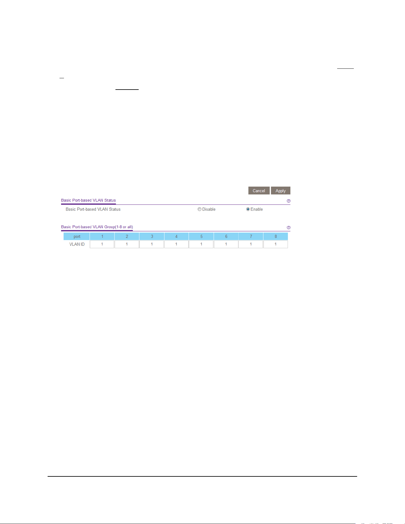
The Basic Port-based VLAN Status page displays.
User Manual30Use VLANS for Traffic
Segmentation
Gigabit Ethernet Plus Switches
6.
If this is the first time that you are accessing this page or if you are changing the
VLAN assignment method, select the Enable radio button and continue with Step
7.
Otherwise, see Step 9.
A pop-up window opens, informing you that the current VLAN settings will be lost.
7. Click the OK button.
The pop-up window closes.
8. Click the Apply button.
Your settings are saved.
The Basic Port-based VLAN Group table displays.
The previous figure is an example. Your switch might provide more or fewer ports.
9.
Under each port to be added to a VLAN, enter the ID of the VLAN.
You can enter a VLAN ID from 1 to the maximum number of ports that your switch
supports. If all the VLANs share an uplink to the Internet or servers, enter all in the
VLAN ID field for the port that you want to use for the uplink.
Note: If ports are members of the same LAG, you must assign them to the same
VLAN.
10. Click the Apply button.
Your settings are saved.
Advanced port-based VLANs: Assign ports
to multiple VLANs
A port-based VLAN configuration lets you assign ports on the switch to a VLAN. The
number of VLANs is limited to the number of ports on the switch. In an advanced
port-based VLAN configuration, you can assign a single port to multiple VLANs.
User Manual31Use VLANS for Traffic
Segmentation
Gigabit Ethernet Plus Switches

By default, all ports are members of VLAN 1.
To assign ports to multiple port-based VLANs:
1. Connect your computer to the same network as the switch.
You can use a WiFi or wired network connection, or connect directly to a switch that
is off-network using an Ethernet cable.
2. Launch a web browser.
3.
In the address field of your web browser, enter the IP address of the switch.
If you do not know the IP address of the switch, see Access the switch using a web
browser on page 17.
The login window opens.
4. Enter the switch password.
The password is the one that you specified the first time that you logged in. The
password is case-sensitive.
The Switch Information page displays.
5. Select VLAN.
The Basic Port-based VLAN Status page displays.
6.
If this is the first time that you are accessing this page or if you are changing the
VLAN assignment method, select the Enable radio button and continue with Step
7.
Otherwise, see Step 9.
A pop-up window opens, informing you that the current VLAN settings will be lost.
7. Click the OK button.
The pop-up window closes.
8. Click the Apply button.
Your settings are saved.
User Manual32Use VLANS for Traffic
Segmentation
Gigabit Ethernet Plus Switches
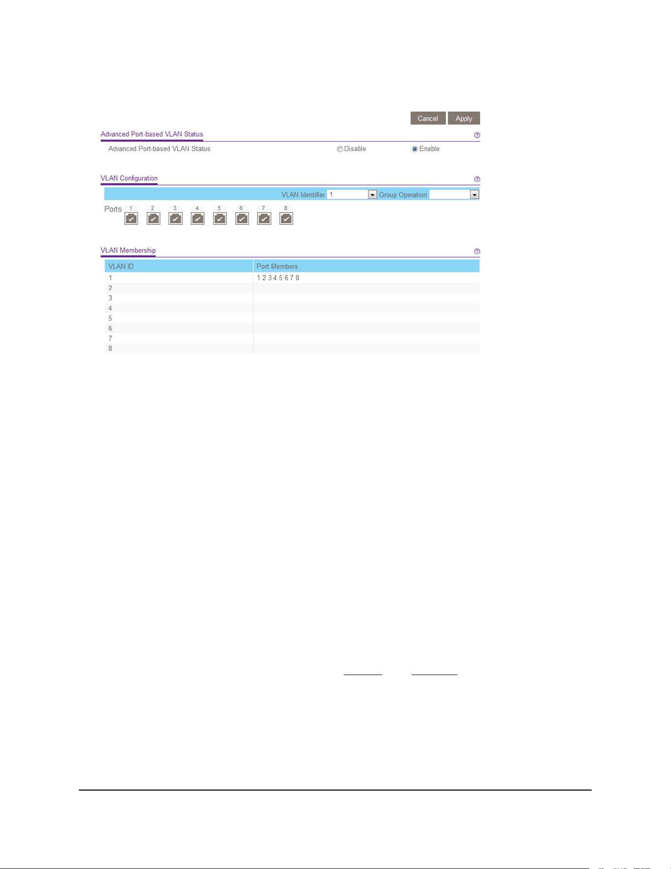
The VLAN Configuration and VLAN Membership sections display.
The previous figure is an example. Your switch might provide more or fewer ports.
9.
In the VLAN Identifier menu, select the VLAN.
10.
Select the ports that you want to add to the VLAN by doing the following:
a. (Optional) In the Group Operation menu, select either Select All or Remove
All.
All ports are either added to the VLAN or removed from the VLAN.
b. Select or remove individual ports by selecting the check boxes that are associated
with the port numbers.
Note: If ports are members of the same LAG, you must assign them to the same
VLAN.
c. Click the Apply button.
Your settings are saved. In the VLAN Membership table, the ports display as
members of the VLAN.
11.
To select ports for another VLAN, repeat Step 9 and Step 10.
User Manual33Use VLANS for Traffic
Segmentation
Gigabit Ethernet Plus Switches

Basic 802.1Q-based VLANs: Assign ports to
VLANs
An 802.1Q-based VLAN configuration lets you assign ports on the switch to a VLAN
with an ID number in the range of 1–4093. By default, all ports are members of VLAN
1.
In an advanced 802.1Q-based VLAN configuration, you can set up VLANs to which you
can add tagged or untagged ports and you can use port VLAN ID (PVID). For more
information, Advanced 802.1Q-based VLANs: Create VLANs on page 35.
To assign ports to basic 802.1Q-based VLANs:
1. Connect your computer to the same network as the switch.
You can use a WiFi or wired network connection, or connect directly to a switch that
is off-network using an Ethernet cable.
2. Launch a web browser.
3.
In the address field of your web browser, enter the IP address of the switch.
If you do not know the IP address of the switch, see Access the switch using a web
browser on page 17.
The login window opens.
4. Enter the switch password.
The password is the one that you specified the first time that you logged in. The
password is case-sensitive.
The Switch Information page displays.
5. Select VLAN > 802.1Q.
The Basic 802.1Q VLAN Status page displays.
6.
If this is the first time that you are accessing the Basic 802.1Q VLAN Status page or
if you are changing the VLAN assignment method, select the Enable radio button
and continue with Step 7.
Otherwise, see Step 9.
A pop-up window opens, informing you that the current VLAN settings will be lost.
7. Click the OK button.
The pop-up window closes.
8. Click the Apply button.
Your settings are saved.
User Manual34Use VLANS for Traffic
Segmentation
Gigabit Ethernet Plus Switches
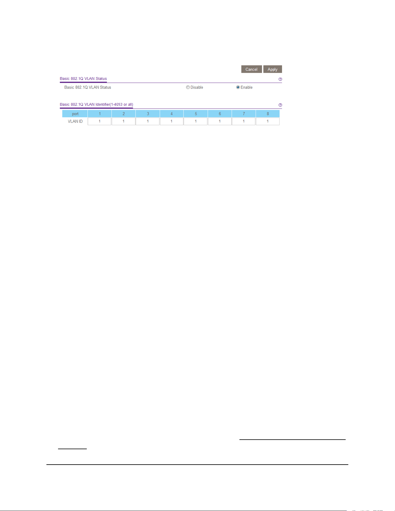
The Basic 802.1Q VLAN Identifier table displays.
The previous figure is an example. Your switch might provide more or fewer ports.
9.
Under each port to be added to a VLAN, enter the ID of the VLAN.
You can enter a VLAN ID from 1 to 4093. If all the VLANs share an uplink to the
Internet or servers, enter all in the VLAN ID field for the port that you want to use
for the uplink.
Note: If ports are members of the same LAG, you must assign them to the same
VLAN.
10. Click the Apply button.
Your settings are saved.
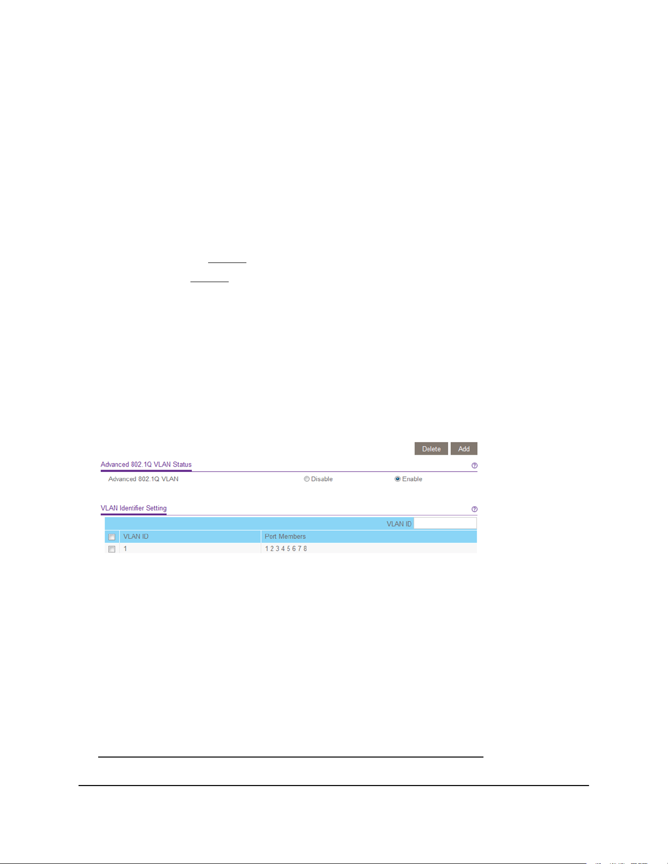
Advanced 802.1Q-based VLANs: Create
VLANs
In an advanced 802.1Q-based VLAN configuration, you can assign ports on the switch
to a VLAN with an ID number in the range of 1–4093 and you can add tagged or
untagged ports to a VLAN. In addition, you can use port VLAN IDs (PVIDs). By default,
all ports are untagged members of VLAN 1.
To create 802.1Q-based VLANs in an advanced configuration:
1. Connect your computer to the same network as the switch.
You can use a WiFi or wired network connection, or connect directly to a switch that
is off-network using an Ethernet cable.
2. Launch a web browser.
3.
In the address field of your web browser, enter the IP address of the switch.
If you do not know the IP address of the switch, see Access the switch using a web
browser on page 17.
The login window opens.
User Manual35Use VLANS for Traffic
Segmentation
Gigabit Ethernet Plus Switches
4. Enter the switch password.
The password is the one that you specified the first time that you logged in. The
password is case-sensitive.
The Switch Information page displays.
5.
Select VLAN > 802.1Q > Advanced > VLAN Configuration.
The Advanced 802.1Q VLAN Status page displays.
6.
If this is the first time that you are accessing the Advanced 802.1Q VLAN Status page
or if you are changing the VLAN assignment method, select the Enable radio button
and continue with Step 7.
Otherwise, see Step 9.
A pop-up window opens, informing you that the current VLAN settings will be lost.
7. Click the OK button.
The pop-up window closes.
8. Click the Apply button.
Your settings are saved.
The VLAN Identifier Setting table displays.
The previous figure is an example. Your switch might provide more or fewer ports,
all of which are members of VLAN 1 by default.
9.
In the VLAN ID field, enter a VLAN ID.
You can enter a VLAN ID from 1 to 4093.
10. Click the Add button.
The new VLAN is added to the VLAN Identifier Setting table.
After you create a new VLAN ID, use the VLAN membership option to add ports to
the VLAN. (Select VLAN > 802.1Q > Advanced > VLAN Membership. See also
Advanced 802.1Q-based VLANs: Add tagged or untagged ports on page 37.)
User Manual36Use VLANS for Traffic
Segmentation
Gigabit Ethernet Plus Switches

Note: To delete a VLAN, select the check box for the VLAN and click the Delete
button.
Advanced 802.1Q-based VLANs: Add
tagged or untagged ports
After you define a VLAN ID using the advanced 802.1Q VLAN option (see Advanced
802.1Q-based VLANs: Create VLANs on page 35), you must add ports to the VLAN.
While you add ports to a VLAN, you can specify whether the ports must be tagged or
untagged. Port tagging allows a port to be associated with a particular VLAN and allows
the VLAN ID tag to be added to data packets that are sent through the port. The tag
identifies the VLAN that must receive the data.
By default, all ports are untagged.
To add tagged or untagged ports to an advanced 802.1Q-based VLAN:
1. Connect your computer to the same network as the switch.
You can use a WiFi or wired network connection, or connect directly to a switch that
is off-network using an Ethernet cable.
2. Launch a web browser.
3.
In the address field of your web browser, enter the IP address of the switch.
If you do not know the IP address of the switch, see Access the switch using a web
browser on page 17.
The login window opens.
4. Enter the switch password.
The password is the one that you specified the first time that you logged in. The
password is case-sensitive.
The Switch Information page displays.
5.
Select VLAN > 802.1Q > Advanced > VLAN Configuration.
The Advanced 802.1Q VLAN Status page displays. The menu on the left displays
more options.
6. Select VLAN Membership.
User Manual37Use VLANS for Traffic
Segmentation
Gigabit Ethernet Plus Switches

You can select VLAN Membership only if you already enabled the advanced 802.1Q
VLAN option (see Advanced 802.1Q-based VLANs: Create VLANs on page 35).
The previous figure is an example. Your switch might provide more or fewer ports.
7. In the VLAN ID menu, select the VLAN.
8.
Select the ports that you want to add to the VLAN by doing the following:
a. (Optional) In the Group Operation menu, select Untag All, Tag all, or Remove
all.
All ports are either added to the VLAN (tagged or untagged) or removed from
the VLAN.
b. Select individual ports and assign them as tagged (T) or untagged (U) ports or
remove individual ports by selecting the check boxes that are associated with
the port numbers.
By default, all ports are untagged.
c. Click the Apply button.
Your settings are saved. In the VLAN Membership table, the ports display as
members of the VLAN.
9.
To select ports for another VLAN, repeat Step 7 and Step 8.
10.
To verify your selections, select VLAN > 802.1Q > Advanced > VLAN Configuration.
The Advanced 802.1Q VLAN Status page displays. In the VLAN Identifier Setting
table, the ports display next to the VLAN or VLANs to which they were added.
Advanced 802.1Q-based VLANs: Specify a
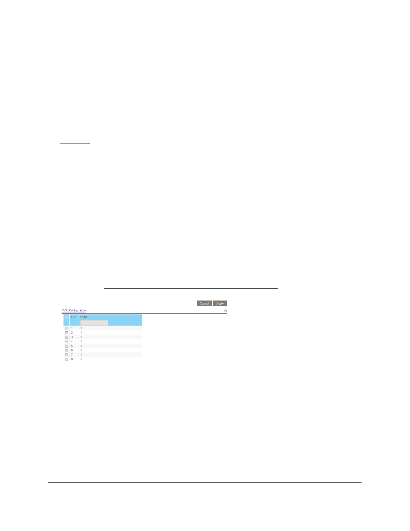
port PVID
A default port VLAN ID (PVID) is a VLAN ID tag that the switch assigns to data packets
it receives that are not already addressed (tagged) for a particular VLAN. For example,
if you connected a computer on port 6 and you want it to be a part of VLAN 2, configure
port 6 to automatically add a PVID of 2 to all data received from the computer. This step
ensures that the data from the computer on port 6 can be seen only by other members
of VLAN 2. You can assign only one PVID to a port.
User Manual38Use VLANS for Traffic
Segmentation
Gigabit Ethernet Plus Switches
To assign a PVID to one or more ports:
1. Connect your computer to the same network as the switch.
You can use a WiFi or wired network connection, or connect directly to a switch that
is off-network using an Ethernet cable.
2. Launch a web browser.
3.
In the address field of your web browser, enter the IP address of the switch.
If you do not know the IP address of the switch, see Access the switch using a web
browser on page 17.
The login window opens.
4. Enter the switch password.
The password is the one that you specified the first time that you logged in. The
password is case-sensitive.
The Switch Information page displays.
5.
Select VLAN > 802.1Q > Advanced > VLAN Configuration.
The Advanced 802.1Q VLAN Status page displays. The menu on the left displays
more options.
6. Select Port PVID.
You can select Port PVID only if you already enabled the advanced 802.1Q VLAN
option (see Advanced 802.1Q-based VLANs: Create VLANs on page 35).
The previous figure is an example. Your switch might provide more or fewer ports.
7. Select one or more ports.
8. Enter the PVID.
You can enter a PVID only for a VLAN that already exists.
9. Click the Apply button.
Your settings are saved.
User Manual39Use VLANS for Traffic
Segmentation
Gigabit Ethernet Plus Switches


About Quality of Service
To manage traffic on the switch, you can manually set the Quality of Service (QoS) mode.
The switch supports the following QoS modes, which are mutually exclusive and, once
selected, apply to all ports on the switch:
•
Port-based QoS mode: Lets you manually set the priority level for individual ports.
For example, you can select Low Priority (P0). For more information, see Set
port-based QoS and set the priority level for one or more ports on page 41.
•
802.1p/DSCP QoS mode: Automatically applies pass-through prioritization for
traffic (for example, voice or video) that is based on tagged packets. This QoS mode
applies to all ports but only for traffic for connected devices that support 802.1p
tagging or Differentiated Services Code Point (DSCP) tagging. For connected devices
that do not support 802.1p or DSCP tagging, traffic is not prioritized. For more
information, see Set 802.1p/DSCP-based QoS for all ports on page 43.
Note: 802.1p-based QoS is available on all models. DSCP-based QoS is available
on models GS105Ev2, GS105PEv2, GS108Ev3, GS108PEv3, GS305E, and GS308E
only.
Independently of the selected QoS mode, the switch supports the following QoS features:
•
Rate limiting: You can limit the rate of traffic on a port, including incoming traffic,
outgoing traffic, or both, to prevent the port and the connected device from taking
up too much bandwidth on the switch. Rate limiting simply means that the switch
slows down all traffic on the port so that traffic does not exceed the limit that you set
for that port. If you set the rate limit on a port too low, you might notice degraded
video stream quality, sluggish response times during online activity, and other
problems. For more information, see Set up rate limiting on page 44.
•
Broadcast filtering: Broadcast filtering is a security feature that can prevent a
transmission delay or blockage if a broadcast storm occurs. You can also set the
storm control rate for incoming traffic for individual ports. For more information, see
Set up broadcast filtering on page 46.
Set port-based QoS and set the priority level
for one or more ports
You can assign a priority to all data passing through a particular port. Data with a higher
priority is transmitted faster. If packets arrive at several ports at the same time, the ports
User Manual41Optimize Performance With
Quality of Service
Gigabit Ethernet Plus Switches

configured as higher priority transmit their packets first. You must determine which
ports will carry delay-sensitive data.
To set port-based QoS and set the priority level for one or more ports:
1. Connect your computer to the same network as the switch.
You can use a WiFi or wired network connection, or connect directly to a switch that
is off-network using an Ethernet cable.
2. Launch a web browser.
3.
In the address field of your web browser, enter the IP address of the switch.
If you do not know the IP address of the switch, see Access the switch using a web
browser on page 17.
The login window opens.
4. Enter the switch password.
The password is the one that you specified the first time that you logged in. The
password is case-sensitive.
The Switch Information page displays.
5. Select QoS.
The Quality of Service page displays.
6.
If this is the first time that you are setting up port-based QoS, select the Port-based
radio button and continue with the next step.
Otherwise, see Step 9.
A pop-up window opens, informing you that the current QoS settings will be lost.
7. Click the OK button.
The pop-up window closes.
8. Click the Apply button.
User Manual42Optimize Performance With
Quality of Service
Gigabit Ethernet Plus Switches
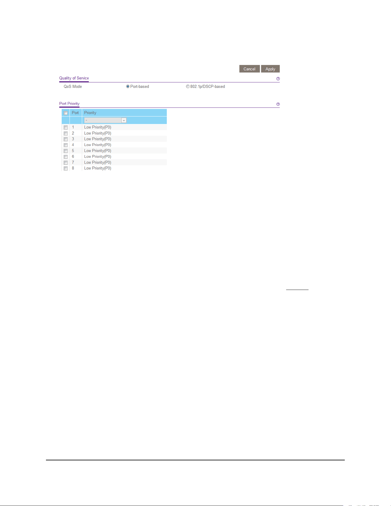
Your settings are saved and the Port Priority table displays.
The previous figure is an example. Your switch might provide more or fewer ports.
The 802.1p/DSCP-based radio button is not supported on all models and therefore
might not show on the page.
9.
To set the port priority for one or more ports, do the following:
a. Select one or more ports.
b. In the Priority menu, select the priority.
c. Click the Apply button.
Your settings are saved. The same priority is applied to all ports that you selected.
10.
To set a different port priority for one or more other ports, repeat Step 9.
Set 802.1p/DSCP-based QoS for all ports
Note: 802.1p-based QoS is available on all models. DSCP-based QoS is available on
models GS105Ev2, GS105PEv2, GS108Ev3, GS108PEv3, GS305E, and GS308E only.
802.1p/DSCP-based priority uses a field in the data packet header that identifies the
class of data in the packet (for example, voice or video). When 802.1p/DSCP-based
priority is used, the switch reads information in the packet header to determine the
priority to assign to the packet. The switch reads both 802.1p tag information and
DSCP/ToS tag information. If an ingress packet contains both an 802.1p tag and a
DSCP/ToS tag, the switch gives precedence to the 802.1p tag.
All ports on the switch check the packet header and transmit the packet with a priority
determined by the packet content.
User Manual43Optimize Performance With
Quality of Service
Gigabit Ethernet Plus Switches

To set 802.1p/DSCP-based QoS for all ports:
1. Connect your computer to the same network as the switch.
You can use a WiFi or wired network connection, or connect directly to a switch that
is off-network using an Ethernet cable.
2. Launch a web browser.
3.
In the address field of your web browser, enter the IP address of the switch.
If you do not know the IP address of the switch, see Access the switch using a web
browser on page 17.
The login window opens.
4. Enter the switch password.
The password is the one that you specified the first time that you logged in. The
password is case-sensitive.
The Switch Information page displays.
5. Select QoS.
The Quality of Service page displays.
6.
Select the 802.1p/DSCP-based radio button.
A pop-up window opens, informing you that the current QoS settings will be lost.
7. Click the OK button.
The pop-up window closes.
8. Click the Apply button.
Your settings are saved.
Set up rate limiting
You can limit the rate at which the switch accepts incoming data and the rate that it
retransmits outgoing data. The rate choices vary depending on the switch model.
Rate limiting can be set for a port in addition to other QoS settings. If the port rate limit
is set, the switch restricts the acceptance or retransmission of data to the values
configured.
User Manual44Optimize Performance With
Quality of Service
Gigabit Ethernet Plus Switches
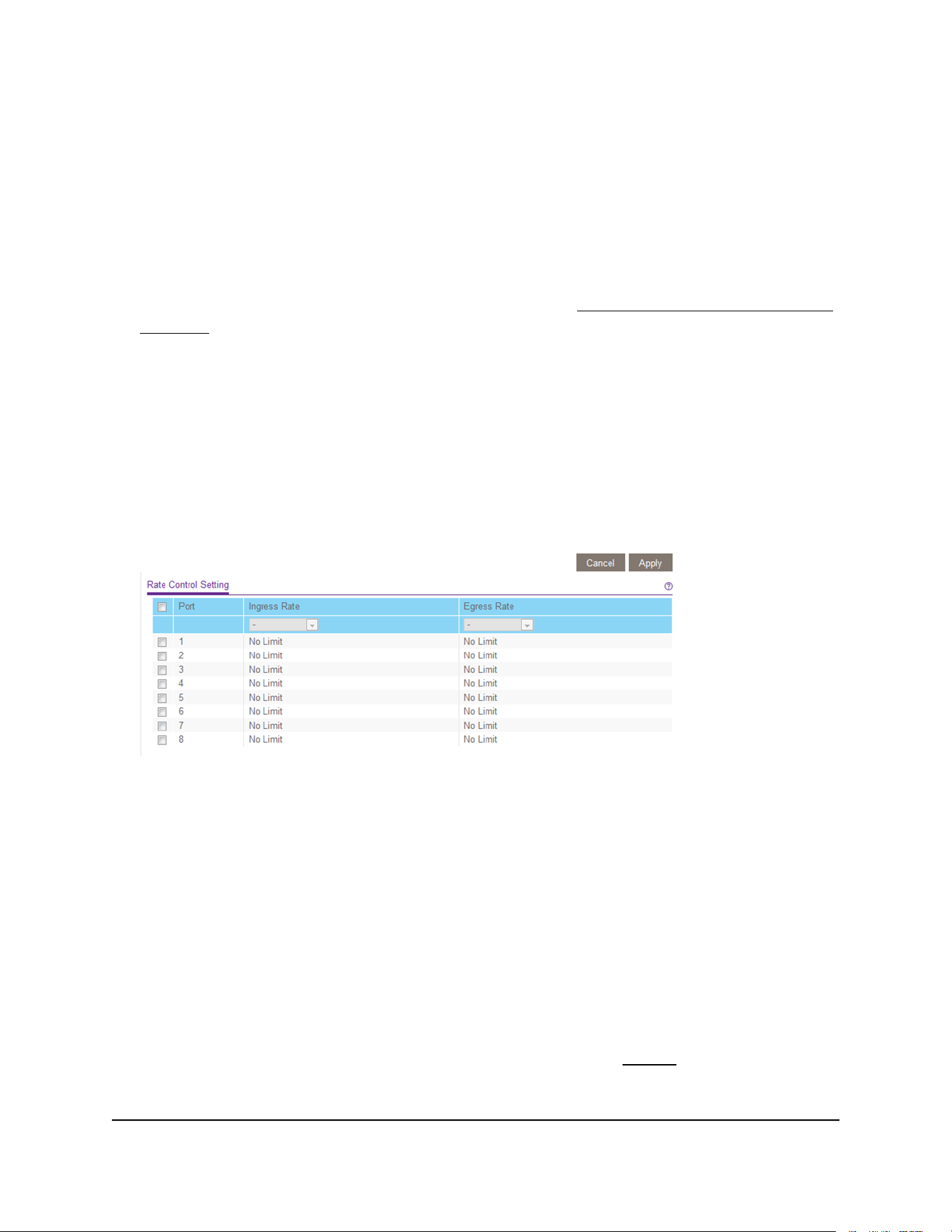
To set up rate limiting:
1. Connect your computer to the same network as the switch.
You can use a WiFi or wired network connection, or connect directly to a switch that
is off-network using an Ethernet cable.
2. Launch a web browser.
3.
In the address field of your web browser, enter the IP address of the switch.
If you do not know the IP address of the switch, see Access the switch using a web
browser on page 17.
The login window opens.
4. Enter the switch password.
The password is the one that you specified the first time that you logged in. The
password is case-sensitive.
The Switch Information page displays.
5. Select QoS > Rate Limit.
The previous figure is an example. Your switch might provide more or fewer ports.
6.
Set the ingress (incoming) and egress (outgoing) traffic rates by doing the following:
a. Select one or more ports.
b. In the Ingress Rate menu, select the maximum rate.
You can set a rate from 512 Kbit/s to 512 Mbit/s. By default, no limit is set.
c. In the Egress Rate menu, select the maximum rate.
You can set a rate from 512 Kbit/s to 512 Mbit/s. By default, no limit is set.
d. Click the Apply button.
Your settings are saved.
7.
To set different rates for one or more other ports, repeat Step 6.
User Manual45Optimize Performance With
Quality of Service
Gigabit Ethernet Plus Switches

Set up broadcast filtering
You can configure the switch to block broadcast storms (massive transmission of
broadcast packets forwarded to every port on the same VLAN). If they are not blocked,
broadcast storms can delay or halt the transmission of other data. Some switches allow
you to select a storm control rate for each port. Others assign a predetermined storm
control rate for all ports on the switch.
If broadcast traffic on any port exceeds the threshold that you set, the switch temporarily
blocks (discards) the broadcast packets.
To set up broadcast filtering:
1. Connect your computer to the same network as the switch.
You can use a WiFi or wired network connection, or connect directly to a switch that
is off-network using an Ethernet cable.
2. Launch a web browser.
3.
In the address field of your web browser, enter the IP address of the switch.
If you do not know the IP address of the switch, see Access the switch using a web
browser on page 17.
The login window opens.
4. Enter the switch password.
The password is the one that you specified the first time that you logged in. The
password is case-sensitive.
The Switch Information page displays.
5. Select QoS > Broadcast Filtering.
The Broadcast Filtering page displays.
6.
If this is the first time that you are setting up broadcast filtering, select the Enable
radio button and continue with the next step.
Otherwise, see Step 8.
7. Click the Apply button.
User Manual46Optimize Performance With
Quality of Service
Gigabit Ethernet Plus Switches
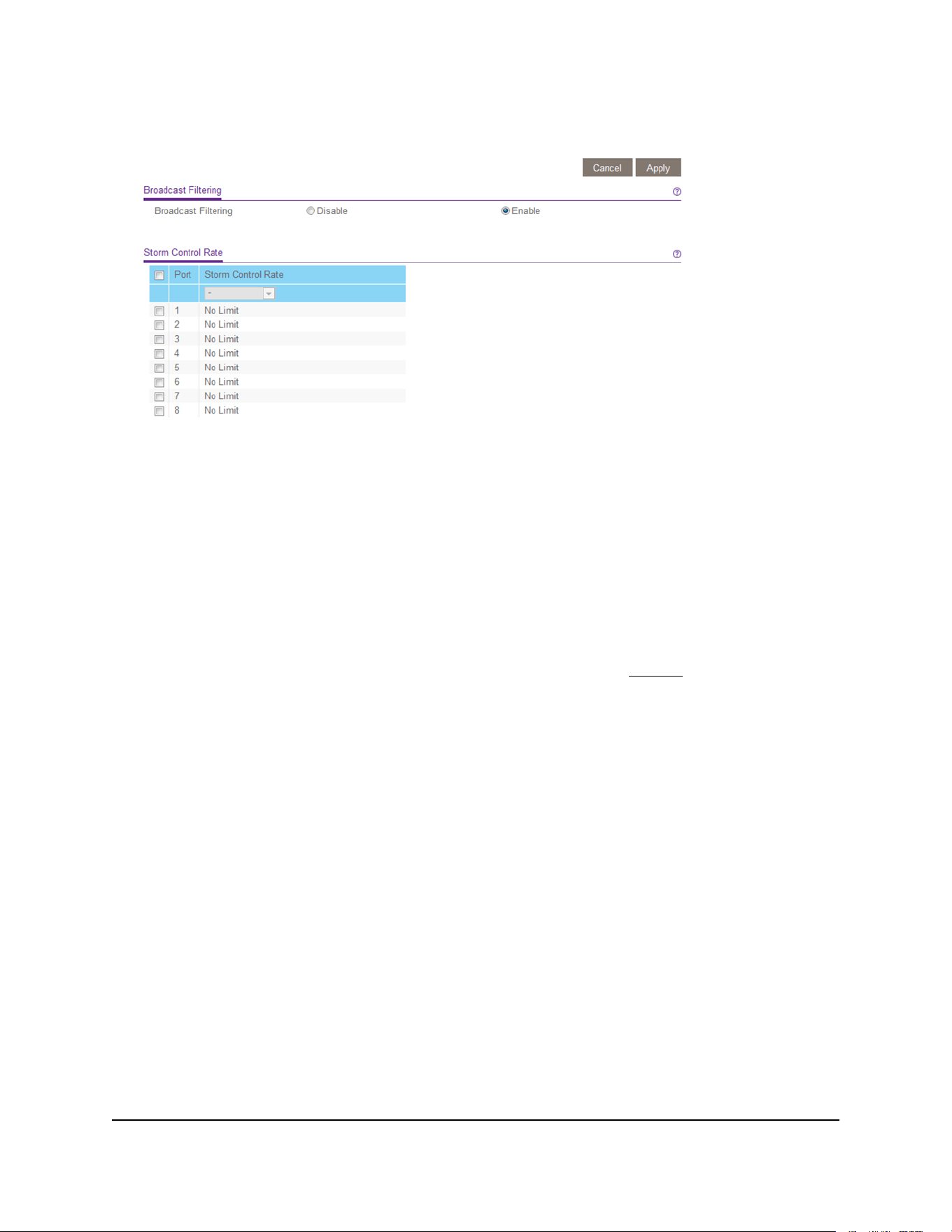
Your settings are saved and the Storm Control Rate table displays.
The previous figure is an example. Your switch might provide more or fewer ports.
8.
Set the storm control rate by doing the following:
a. Select one or more ports.
b. In the Storm Control Rate menu, select the maximum rate.
You can set a rate from 512 Kbit/s to 512 Mbit/s. By default, no limit is set.
c. Click the Apply button.
Your settings are saved.
9.
To set a different rate for one or more other ports, repeat Step 8.
User Manual47Optimize Performance With
Quality of Service
Gigabit Ethernet Plus Switches


Specify IP address settings for the switch
By default, the switch IP address works as follows:
•
If you cable the switch to a network with a DHCP server before you power on the
switch, the DHCP server assigns an IP address to the switch when the switch is
powered on.
•
If you power on the switch when it is not connected to a network with a DHCP server,
the switch uses its default IP address, which is 192.168.0.239.
You can disable the DHCP mode in the switch and enter static IP address and subnet
mask values for the switch as well as the address of the gateway device used by the
switch.
Change the switch IP address
To change IP address settings for the switch:
1. Connect your computer to the same network as the switch.
You can use a WiFi or wired network connection, or connect directly to a switch that
is off-network using an Ethernet cable.
2. Launch a web browser.
3.
In the address field of your web browser, enter the IP address of the switch.
If you do not know the IP address of the switch, see Access the switch using a web
browser on page 17.
The login window opens.
4. Enter the switch password.
The password is the one that you specified the first time that you logged in. The
password is case-sensitive.
The Switch Information page displays.
User Manual49Manage Network Settings
Gigabit Ethernet Plus Switches
5. In the DHCP Mode menu, select Disable.
The IP Address, Subnet Mask, and Gateway Address fields are enabled.
6. Enter the IP address, subnet mask, and gateway address.
7. Click the Apply button.
Your settings are saved.
Manage multicast traffic with IGMP snooping
Internet Group Management Protocol (IGMP) snooping allows a switch to forward
multicast traffic intelligently on the switch. Multicast IP traffic is traffic that is destined to
a host group. Host groups are identified by class D IP addresses, which range from
224.0.0.0 to 239.255.255.255. Based on the IGMP query and report messages, the
switch forwards traffic only to the ports that request the multicast traffic. This feature
prevents the switch from broadcasting the traffic to all ports and possibly affecting
network performance.
The switch maintains a map that shows which links need which IP multicast streams. The
switch forwards multicast traffic only to the links that requested them and cuts multicast
traffic from links that do not contain a multicast listener. Essentially, IGMP snooping
helps optimize multicast performance at Layer 2 and is especially useful for
bandwidth-intensive IP multicast applications such as IPTV.
User Manual50Manage Network Settings
Gigabit Ethernet Plus Switches
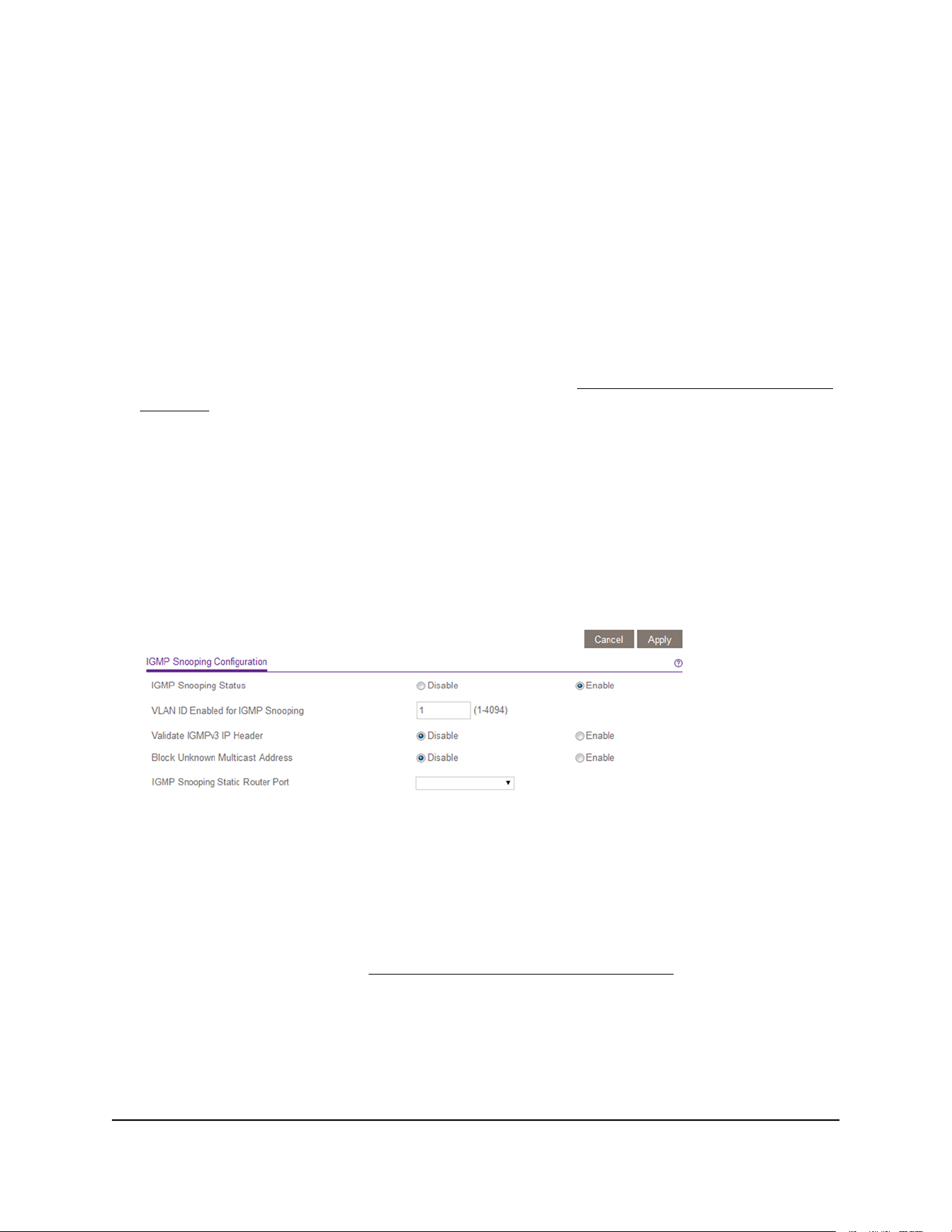
Customize IGMP snooping
By default, IGMP snooping is enabled. You can customize the settings for your network.
To customize IGMP snooping:
1. Connect your computer to the same network as the switch.
You can use a WiFi or wired network connection, or connect directly to a switch that
is off-network using an Ethernet cable.
2. Launch a web browser.
3.
In the address field of your web browser, enter the IP address of the switch.
If you do not know the IP address of the switch, see Access the switch using a web
browser on page 17.
The login window opens.
4. Enter the switch password.
The password is the one that you specified the first time that you logged in. The
password is case-sensitive.
The Switch Information page displays.
5. Select System > Multicast.
6. Make sure that the IGMP Snooping Status Enable radio button is selected.
7.
In the VLAN ID Enabled for IGMP Snooping field, enter a VLAN ID between 1 and
4094.
By default, the VLAN ID is 1.
You can specify a VLAN for IGMP snooping only if you enabled port-based or
802.1Q-based VLANs (see Use VLANS for Traffic Segmentation on page 28).
IGMP snooping functions only on the VLAN that is specified in the VLAN ID Enabled
for IGMP Snooping field.
8. (Optional) Select the Validate IGMPv3 IP header Enable radio button.
User Manual51Manage Network Settings
Gigabit Ethernet Plus Switches

Some network devices might not conform to the IGMPv3 standard. When the Validate
IGMPv3 IP header option is enabled, IGMP messages are required to include TTL = 1,
ToS Byte = 0xC0 (Internetwork Control), and the router alert IP option (9404) must
be set. Otherwise, the packets are ignored.
9. (Optional) Select the Block Unknown MultiCast Address Enable radio button.
When this feature is enabled, multicast packets are forwarded only to the ports that
are in the multicast group learned from IGMP snooping. All unknown multicast
packets are dropped.
10.
(Optional, for some models only) Select an option from the IGMP Snooping Static
Router Port menu.
You can select a port to be the dedicated IGMP snooping static router port if no
IGMP query exists in the network for the switch to discover the router port
dynamically. After a port is selected as the static router port, all IGMP Join and Leave
reports are forwarded to the port.
11. Click the Apply button.
Your settings are saved.
Specify a VLAN for IGMP snooping
You can specify a VLAN for IGMP snooping only if you enabled port-based or
802.1Q-based VLANs (see Use VLANS for Traffic Segmentation on page 28).
To specify a VLAN for IGMP snooping:
1. Connect your computer to the same network as the switch.
You can use a WiFi or wired network connection, or connect directly to a switch that
is off-network using an Ethernet cable.
2. Launch a web browser.
3.
In the address field of your web browser, enter the IP address of the switch.
If you do not know the IP address of the switch, see Access the switch using a web
browser on page 17.
The login window opens.
4. Enter the switch password.
The password is the one that you specified the first time that you logged in. The
password is case-sensitive.
The Switch Information page displays.
User Manual52Manage Network Settings
Gigabit Ethernet Plus Switches
5. Select System > Multicast.
6. Make sure that the IGMP Snooping Status Enable radio button is selected.
7.
In the VLAN ID Enabled for IGMP Snooping field, enter the ID of the VLAN.
By default, if you enable IGMP snooping, snooping occurs on VLAN 1. However, you
can enable snooping on any VLAN:
•
For port-based VLANs, you can enter a VLAN ID from 1 to the maximum number
of ports that the switch supports.
•
For 802.1Q-based VLANs, you can enter a VLAN ID from 1 to 4094.
8. Click the Apply button.
Your settings are saved.
Set up link aggregation groups
Note: Static link aggregation (port trunking) is supported on models GS116E, JGS516PE,
JGS524E, and JGS524PE.
Link aggregation groups (LAGs) allow you to combine multiple Ethernet links into a
single logical link. Network devices treat the aggregation as if it were a single link, which
increases fault tolerance and load sharing.
The number of LAGs that the switch supports depends on the model.
Configure LAG membership before you enable the LAG.
Note: The switch does not support IEEE 802.3ad Link Aggregation or Link Aggregation
Control Protocol (LACP) groups but supports manual static LAGs only.
You must set up LAG membership before you can enable LAGs.
User Manual53Manage Network Settings
Gigabit Ethernet Plus Switches
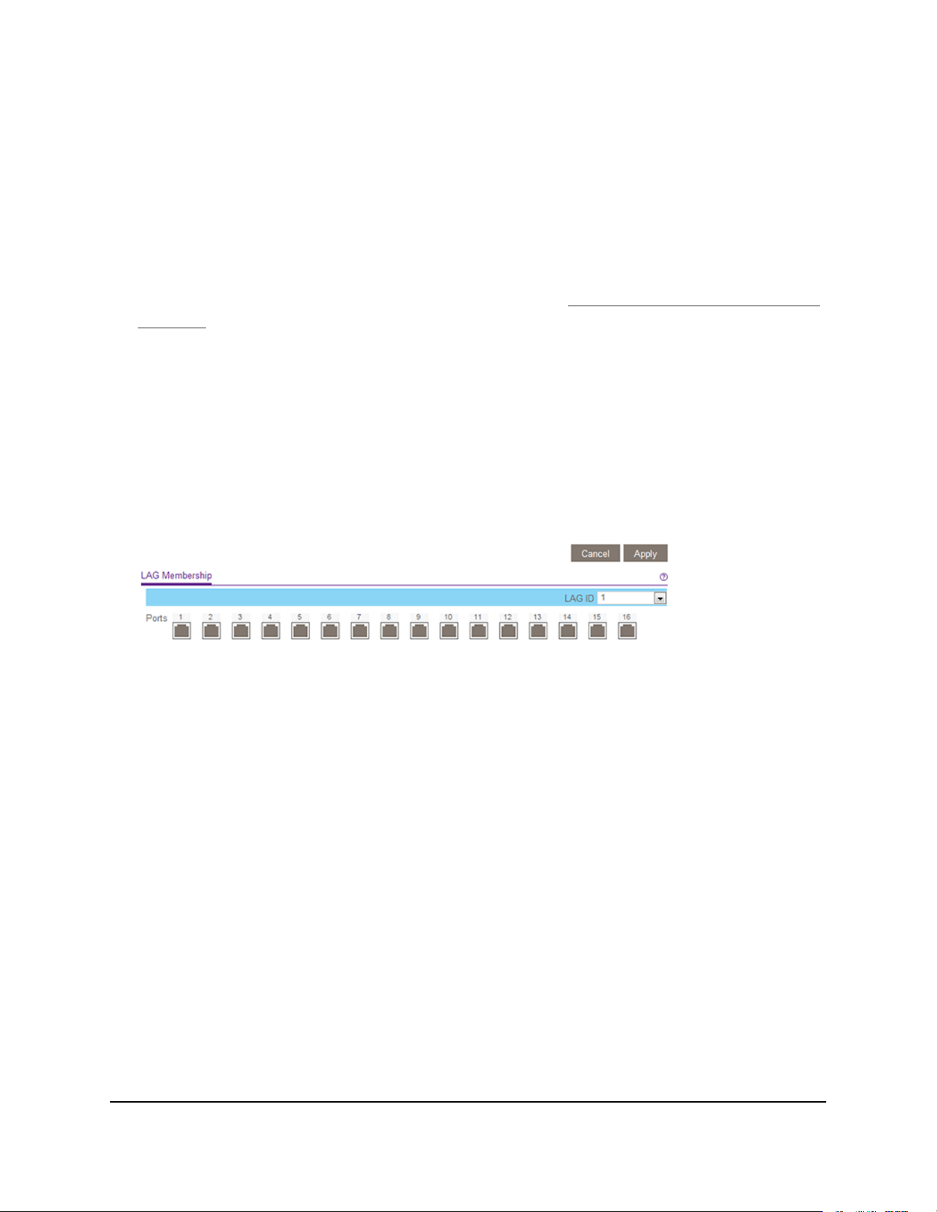
To specify LAG membership and enable a LAG:
1. Connect your computer to the same network as the switch.
You can use a WiFi or wired network connection, or connect directly to a switch that
is off-network using an Ethernet cable.
2. Launch a web browser.
3.
In the address field of your web browser, enter the IP address of the switch.
If you do not know the IP address of the switch, see Access the switch using a web
browser on page 17.
The login window opens.
4. Enter the switch password.
The password is the one that you specified the first time that you logged in. The
password is case-sensitive.
The Switch Information page displays.
5. Select System > LAG > LAG Membership.
The previous figure is an example. Your switch might provide more or fewer ports.
6. In the LAG ID menu, select the LAG ID.
The number of LAGs that the switch supports depends on the model.
7.
Select the ports for the LAG by selecting the check boxes that are associated with
the port numbers.
A LAG consists of at least two ports.
8. Click the Apply button.
Your settings are saved.
User Manual54Manage Network Settings
Gigabit Ethernet Plus Switches

9.
Select System > LAG > LAG Configuration.
10.
Select the ID of the LAG for which you just set up the port membership.
11. In the Admin Mode menu, select Enable.
12. Click the Apply button.
Your settings are saved.
User Manual55Manage Network Settings
Gigabit Ethernet Plus Switches

6
Manage and Monitor the Switch
This chapter covers the following topics:
• Manage flow control
• Manage the port speed and the port status
• Enable loop detection
• Manage power saving options
• Download and update the firmware
• Reboot the switch
• Save the switch configuration
• Restore a saved switch configuration
• Restore factory default settings
• Manage access control
• Enable port mirroring
• View switch information or change the switch device name
• Change the switch password
• View or clear the port statistics
• PoE considerations for switches that support PoE
56
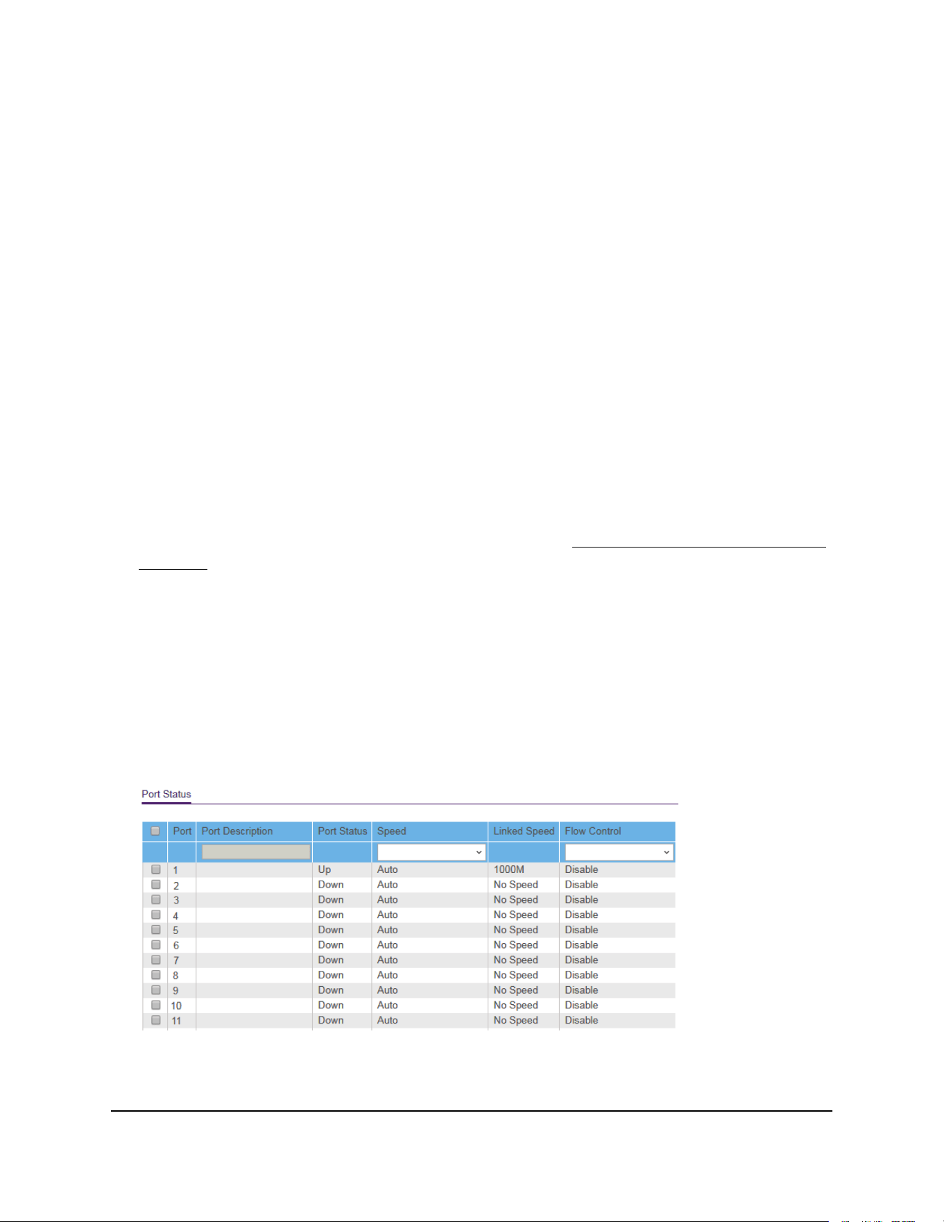
Manage flow control
Note: Flow control is available on models GS105Ev2, GS105PE, GS108Ev3, GS108PEv3,
GS305E, and GS308E.
Flow control works by pausing a port if the port becomes oversubscribed. It drops all
traffic for small intervals of time during the congested condition. By default, flow control
is disabled. (For some network situations, flow control might not work well.) You can
enable or disable IEEE 802.3x flow control.
To manage flow control:
1. Connect your computer to the same network as the switch.
You can use a WiFi or wired network connection, or connect directly to a switch that
is off-network using an Ethernet cable.
2. Launch a web browser.
3.
In the address field of your web browser, enter the IP address of the switch.
If you do not know the IP address of the switch, see Access the switch using a web
browser on page 17.
The login window opens.
4. Enter the switch password.
The password is the one that you specified the first time that you logged in. The
password is case-sensitive.
The Switch Information page displays.
5. Select System > Management > Port Status.
The previous figure is an example. Your switch might provide more or fewer ports.
6. Select one or more ports.
User Manual57Manage and Monitor the Switch
Gigabit Ethernet Plus Switches
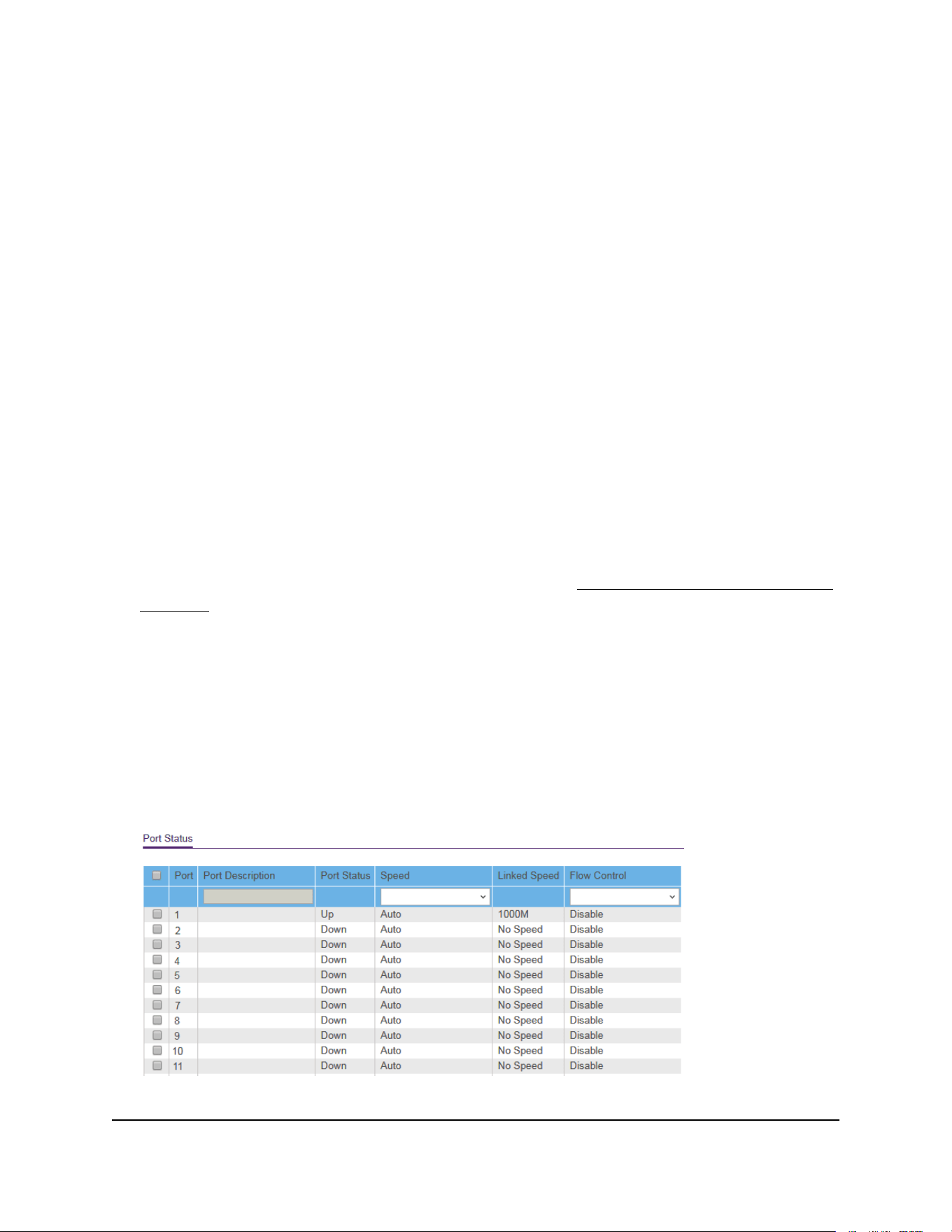
7. In the Flow Control menu, select Enable or Disable.
8. Click the Apply button.
Your settings are saved.
Manage the port speed and the port status
By default, the port speed on all ports is set automatically after the switch determines
the speed using autonegotiation with the link partner. You can select a specific port
speed setting for each port, or disable a port by shutting it down manually.
To manage the port speed and the port status:
1. Connect your computer to the same network as the switch.
You can use a WiFi or wired network connection, or connect directly to a switch that
is off-network using an Ethernet cable.
2. Launch a web browser.
3.
In the address field of your web browser, enter the IP address of the switch.
If you do not know the IP address of the switch, see Access the switch using a web
browser on page 17.
The login window opens.
4. Enter the switch password.
The password is the one that you specified the first time that you logged in. The
password is case-sensitive.
The Switch Information page displays.
5. Select System > Management > Port Status.
The previous figure is an example. Your switch might provide more or fewer ports.
User Manual58Manage and Monitor the Switch
Gigabit Ethernet Plus Switches

6. Select one or more ports.
7.
In the Speed menu, select one of the following options:
•
Auto. The port speed is set automatically after the switch determines the speed
using autonegotiation with the link partner. This is the default setting.
•
Disable. The port is shut down.
•
10M Half. The port is forced to function at 10 Mbps with half duplex.
•
10M Full. The port is forced to function at 10 Mbps with full duplex.
•
100M Half. The port is forced to function at 100 Mbps with half duplex.
•
100M Full. The port is forced to function at 100 Mbps with full duplex.
8.
If you selected a single port in Step 6, to add a port description, enter a text in the
Port Description field in the table heading.
If you selected more than one port in Step 6, you cannot add a port description.
9.
To configure more ports, repeat this procedure from Step 6 on.
10. Click the Apply button.
Your settings are saved.
Enable loop detection
If loop detection is enabled and the switch detects a loop, the LED or both LEDs of a
port blink at a constant speed.
To enable loop detection:
1. Connect your computer to the same network as the switch.
You can use a WiFi or wired network connection, or connect directly to a switch that
is off-network using an Ethernet cable.
2. Launch a web browser.
3.
In the address field of your web browser, enter the IP address of the switch.
If you do not know the IP address of the switch, see Access the switch using a web
browser on page 17.
The login window opens.
4. Enter the switch password.
The password is the one that you specified the first time that you logged in. The
password is case-sensitive.
User Manual59Manage and Monitor the Switch
Gigabit Ethernet Plus Switches

The Switch Information page displays.
5. Select System > Management > Loop Detection.
The Loop Detection page displays.
6. Select the Enable radio button.
7. Click the Apply button.
Your settings are saved.
Manage power saving options
Note: Power saving options are available on models GS105Ev2, GS105PE, GS116Ev2,
JGS516PE, JGS524Ev2, and JGS524PE.
Depending on the power saving options that your switch model provides, you can
manage the IEEE 802.3az Energy Efficient Ethernet (EEE) function, cable length power
saving, or link-down power saving, or a combination of these features:
•
Short Cable Power Saving. Dynamically detects and adjusts power that is required
for the detected cable length.
•
Link-Down Power Saving. Reduces the power consumption considerably when
the network cable is disconnected. When the network cable is reconnected, the
switch detects an incoming signal and restores normal power.
•
EEE. Combines the Energy Efficient Ethernet (EEE) 802.3 MAC sublayer with the
100BASE-TX and 1000BASE-T physical layers to support operation in Low Power
Idle (LPI) mode. When LPI mode is enabled, systems on both sides of the link can
disable portions of their functionality and save power during periods of low link
utilization.
To manage the power saving options:
1. Connect your computer to the same network as the switch.
You can use a WiFi or wired network connection, or connect directly to a switch that
is off-network using an Ethernet cable.
2. Launch a web browser.
3.
In the address field of your web browser, enter the IP address of the switch.
If you do not know the IP address of the switch, see Access the switch using a web
browser on page 17.
The login window opens.
User Manual60Manage and Monitor the Switch
Gigabit Ethernet Plus Switches

4. Enter the switch password.
The password is the one that you specified the first time that you logged in. The
password is case-sensitive.
The Switch Information page displays.
5. Select System > Management > Power Saving Mode.
6. Select the Enable button to enable the power saving mode.
By default, the Disable radio button is selected.
7. Click the Apply button.
Your settings are saved.
Download and update the firmware
You can manually check for the latest firmware version for your switch by visiting
netgear.com/support/download/.
To download and update the firmware using the device UI:
1. Visit netgear.com/support/download/.
2.
In the Enter a Product Name/Model Number field, start typing the model number,
and select the model from the menu that displays after you start typing.
The available firmware versions displays.
3.
Select and download the firmware version and release notes to your computer.
4.
Read the release notes to find out if you must reconfigure the switch after upgrading.
5.
Unzip the downloaded file to extract the firmware image.
6. Connect your computer to the same network as the switch.
You can use a WiFi or wired network connection, or connect directly to a switch that
is off-network using an Ethernet cable.
7. Launch a web browser.
8.
In the address field of your web browser, enter the IP address of the switch.
User Manual61Manage and Monitor the Switch
Gigabit Ethernet Plus Switches

If you do not know the IP address of the switch, see Access the switch using a web
browser on page 17.
The login window opens.
9. Enter the switch password.
The password is the one that you specified the first time that you logged in. The
password is case-sensitive.
The Switch Information page displays.
10. Select System > Maintenance > Firmware Update.
The Firmware Update page displays.
The firmware update method depends on the current firmware and boot loader
versions on your switch.
11.
If the page displays the Enter Loader Mode button, click the Enter Loader Mode
button.
The switch reboots and enters into the loader mode. The Firmware Upgrade page
that displays varies, depending on the firmware boot loader version that is already
on your switch.
Follow either Step 12 or Step 13, depending on which prompts you are presented
with.
12.
If you are prompted to update the firmware from a file, click the Browse button and
locate and select the new firmware image file.
13.
If you are prompted to provide both the TFTP server IP address and the image file
name, do the following:
a.
Complete the TFTP Server IP address field.
Note: This method requires that TFTP server software is installed on your
computer to use the assigned TFTP server address from the TFTP server software
application.
b.
Complete the Image File Name field.
c. Make sure that the TFTP server launches the TFTP server application.
14. Click the Apply button.
WARNING: To avoid the risk of corrupting the firmware, do not interrupt the update.
For example, do not turn off the switch or disconnect it.
User Manual62Manage and Monitor the Switch
Gigabit Ethernet Plus Switches

When the update is complete, your switch restarts. The update process typically
takes about three minutes.
Reboot the switch
You can reboot the switch remotely.
To reboot the switch:
1. Connect your computer to the same network as the switch.
You can use a WiFi or wired network connection, or connect directly to a switch that
is off-network using an Ethernet cable.
2. Launch a web browser.
3.
In the address field of your web browser, enter the IP address of the switch.
If you do not know the IP address of the switch, see Access the switch using a web
browser on page 17.
The login window opens.
4. Enter the switch password.
The password is the one that you specified the first time that you logged in. The
password is case-sensitive.
The Switch Information page displays.
5. Select System > Maintenance > Device Reboot.
The Device Reboot page displays.
6. Select the check box.
7. Click the Apply button.
The switch reboots.
Save the switch configuration
You can save the switch configuration as a file. We recommend that you save the
configuration. Then you can quickly restore the switch configuration if you change the
settings and then decide to return the switch to its previous settings.
User Manual63Manage and Monitor the Switch
Gigabit Ethernet Plus Switches

To save the switch configuration:
1. Connect your computer to the same network as the switch.
You can use a WiFi or wired network connection, or connect directly to a switch that
is off-network using an Ethernet cable.
2. Launch a web browser.
3.
In the address field of your web browser, enter the IP address of the switch.
If you do not know the IP address of the switch, see Access the switch using a web
browser on page 17.
The login window opens.
4. Enter the switch password.
The password is the one that you specified the first time that you logged in. The
password is case-sensitive.
The Switch Information page displays.
5.
Select System > Maintenance > Save Configuration.
The Save Configuration page displays.
6. Click the Save button.
A pop-up window opens. Depending on the settings of your browser, you can select
a location to save the switch configuration file (a .cfg file).
7.
Follow the directions of your browser to save the switch configuration.
Restore a saved switch configuration
You can restore a switch configuration that you saved.
To restore the switch configuration that you saved:
1. Connect your computer to the same network as the switch.
You can use a WiFi or wired network connection, or connect directly to a switch that
is off-network using an Ethernet cable.
2. Launch a web browser.
3.
In the address field of your web browser, enter the IP address of the switch.
If you do not know the IP address of the switch, see Access the switch using a web
browser on page 17.
The login window opens.
User Manual64Manage and Monitor the Switch
Gigabit Ethernet Plus Switches

4. Enter the switch password.
The password is the one that you specified the first time that you logged in. The
password is case-sensitive.
The Switch Information page displays.
5.
Select System > Maintenance > Restore Configuration.
The Restore Configuration page displays.
6.
Click the Browse button and locate and select the saved configuration file (a .cfg
file).
7. Click the Apply button.
The saved configuration is restored to the switch.
Restore factory default settings
You can return the switch to its factory settings.
CAUTION: This process erases all settings that you configured on the switch.
To restore factory settings:
1. Connect your computer to the same network as the switch.
You can use a WiFi or wired network connection, or connect directly to a switch that
is off-network using an Ethernet cable.
2. Launch a web browser.
3.
In the address field of your web browser, enter the IP address of the switch.
If you do not know the IP address of the switch, see Access the switch using a web
browser on page 17.
The login window opens.
4. Enter the switch password.
The password is the one that you specified the first time that you logged in. The
password is case-sensitive.
The Switch Information page displays.
5.
Select System > Maintenance > Factory Default.
The Factory Default page displays.
6. Select the check box.
User Manual65Manage and Monitor the Switch
Gigabit Ethernet Plus Switches

7. Click the Apply button.
The switch returns to its factory settings. The switch reboots to load the restored
configuration.
Manage access control
Access control allows you to control which devices can access the switch over a web
browser for management purposes. By default, access control is disabled. By adding
one or more devices to the Access Control list, access control is enabled, and only
devices in the list are allowed to access the switch over a web browser.
Note: Models GS108Ev3, GS108PEv3, and GS308E do not support access control.
For more information, see the following sections:
•
Add devices to the Access Control list on page 66
•
Remove devices from the Access Control list on page 67
Add devices to the Access Control list
Be sure to use a valid subnet mask when you add a device or a range of devices to the
Access Control list.
CAUTION: Add the IP address and subnet mask for the device from which you are
accessing the switch to the Access Control list before you add any other devices to the
list. Otherwise, you are locked out from the switch's device UI.
To add devices to the Access Control list:
1. Connect your computer to the same network as the switch.
You can use a WiFi or wired network connection, or connect directly to a switch that
is off-network using an Ethernet cable.
2. Launch a web browser.
3.
In the address field of your web browser, enter the IP address of the switch.
If you do not know the IP address of the switch, see Access the switch using a web
browser on page 17.
The login window opens.
4. Enter the switch password.
User Manual66Manage and Monitor the Switch
Gigabit Ethernet Plus Switches
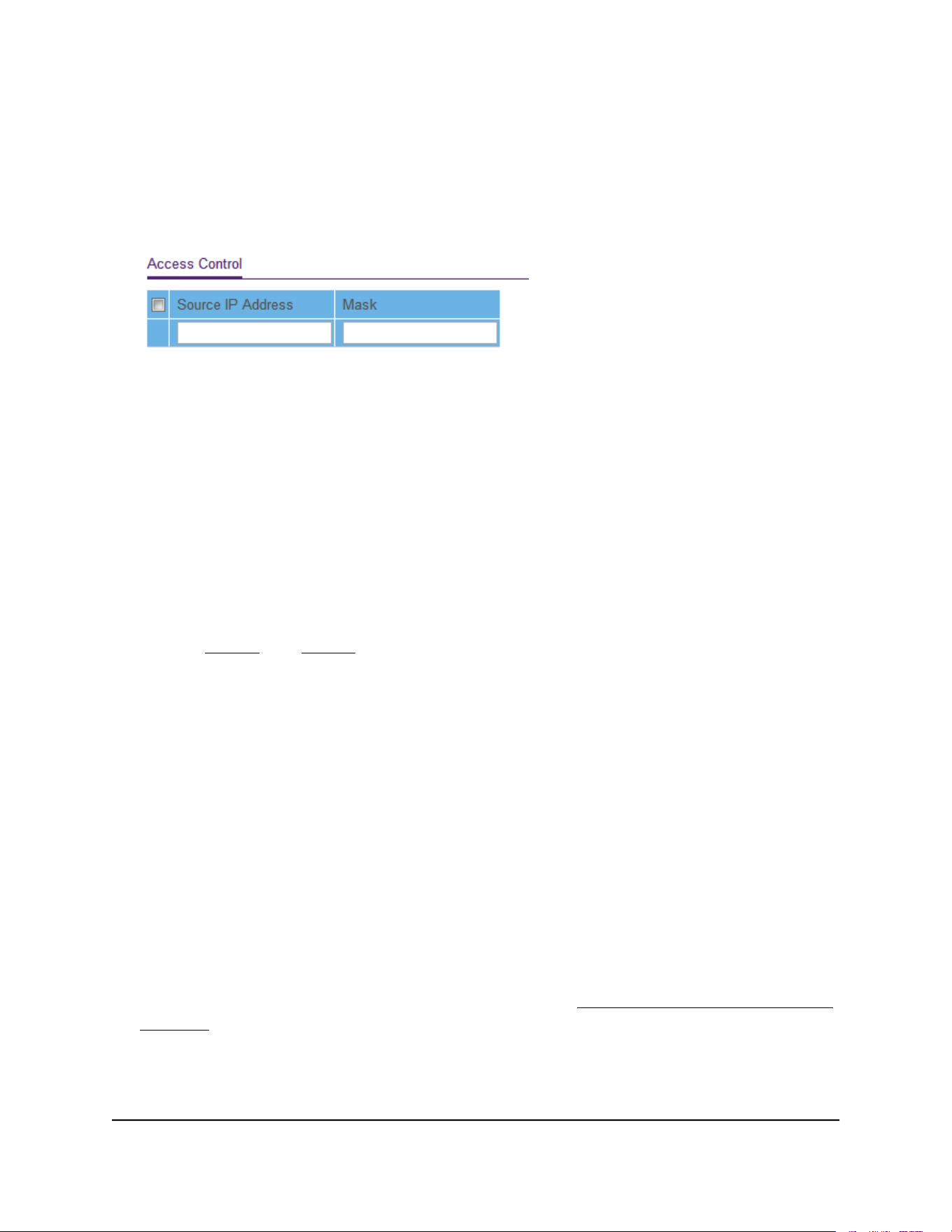
The password is the one that you specified the first time that you logged in. The
password is case-sensitive.
The Switch Information page displays.
5. Select System > Maintenance > Access Control.
6.
For a device or range of devices that must be able to access the switch, configure
the following settings:
•
Source IP Address. Enter the IP address of the device or range of devices that
must be allowed to access the switch over a web browser.
•
Mask. Enter the subnet mask that is associated with the IP address.
7. Click the Add button.
The device or range of devices is added to the list and your settings are saved. Access
control is now enabled.
8.
Repeat Step 6 and Step 7 for each device or range of devices that you want to add
to the Access Control table.
Remove devices from the Access Control list
You can remove a device from the Access Control list. If you remove all devices from
the list, access control is disabled.
To remove devices from the Access Control list:
1. Connect your computer to the same network as the switch.
You can use a WiFi or wired network connection, or connect directly to a switch that
is off-network using an Ethernet cable.
2. Launch a web browser.
3.
In the address field of your web browser, enter the IP address of the switch.
If you do not know the IP address of the switch, see Access the switch using a web
browser on page 17.
The login window opens.
4. Enter the switch password.
User Manual67Manage and Monitor the Switch
Gigabit Ethernet Plus Switches
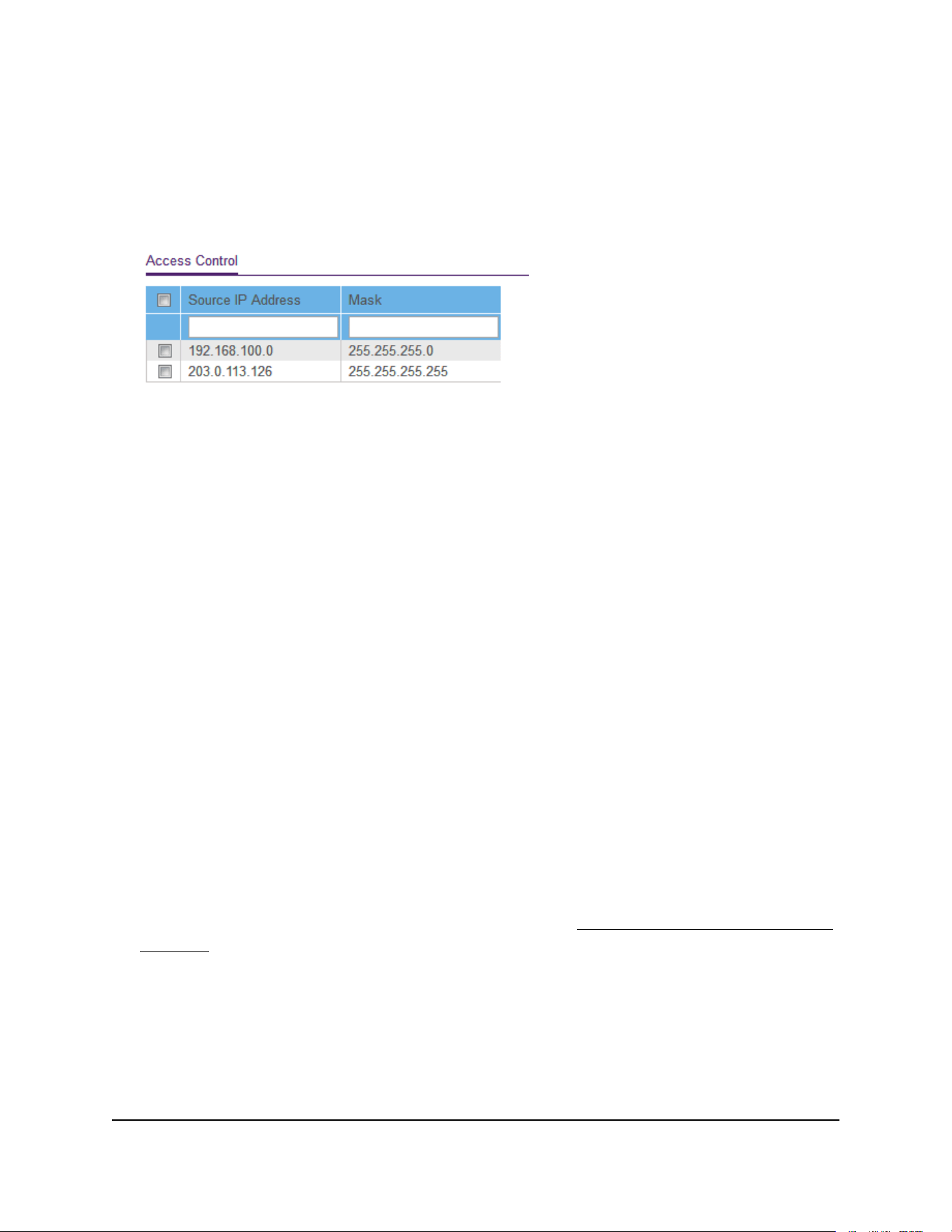
The password is the one that you specified the first time that you logged in. The
password is case-sensitive.
The Switch Information page displays.
5. Select System > Maintenance > Access Control.
6. Select one or more devices.
To select all devices in the list, select the check box in the table heading.
7. Click the Delete button.
The devices are removed from the list and your settings are saved. If you removed
all devices from the list, access control is disabled.
Enable port mirroring
Port mirroring lets you mirror the incoming (ingress) and outgoing (egress) traffic of
one or more ports (the source ports) to a single predefined destination port.
To enable port mirroring:
1. Connect your computer to the same network as the switch.
You can use a WiFi or wired network connection, or connect directly to a switch that
is off-network using an Ethernet cable.
2. Launch a web browser.
3.
In the address field of your web browser, enter the IP address of the switch.
If you do not know the IP address of the switch, see Access the switch using a web
browser on page 17.
The login window opens.
4. Enter the switch password.
The password is the one that you specified the first time that you logged in. The
password is case-sensitive.
The Switch Information page displays.
User Manual68Manage and Monitor the Switch
Gigabit Ethernet Plus Switches

5. Select System > Monitoring > Mirroring.
The previous figure is an example. Your switch might provide more or fewer ports.
6. In the Destination Port menu, select the destination port.
You can select a single destination port only. You cannot select a destination port
that is a member of a LAG.
7. In the Source Port section, select one or more source ports by selecting the check
boxes that are associated with the port numbers.
You can select more than one source port. You cannot select a source port that is a
member of a LAG.
8. In the Mirroring menu, select Enable.
By default, mirroring is disabled.
9. Click the Apply button.
Your settings are saved.
View switch information or change the switch
device name
You can view the switch product name (model), serial number, MAC address, firmware
version, DHCP mode, and other network information.
You can also change the switch device name.
To view information about the switch or change the switch device name:
1. Connect your computer to the same network as the switch.
You can use a WiFi or wired network connection, or connect directly to a switch that
is off-network using an Ethernet cable.
2. Launch a web browser.
3.
In the address field of your web browser, enter the IP address of the switch.
User Manual69Manage and Monitor the Switch
Gigabit Ethernet Plus Switches
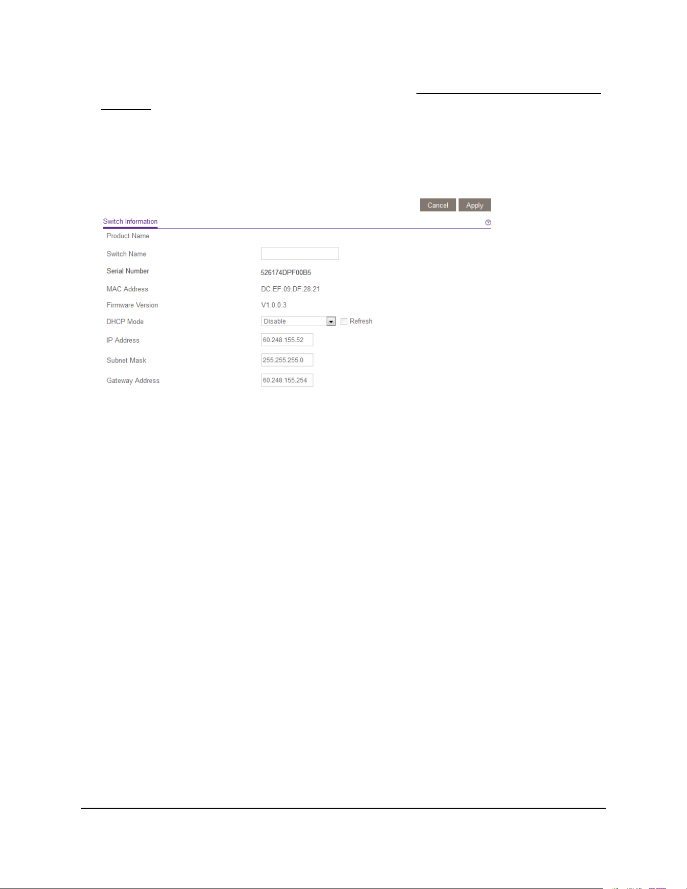
If you do not know the IP address of the switch, see Access the switch using a web
browser on page 17.
The login window opens.
4. Enter the switch password.
The default password is password. The password is case-sensitive.
To navigate to this page, select System > Management > Switch Information.
5.
To change the switch device name, do the following:
a.
In the Switch Name field, enter a name of up to 20 characters.
b. Click the Apply button.
Your settings are saved.
Change the switch password
The default password to access the switch is password. The first time that you log in to
the switch, you must change the default password.
You can change the password again. The ideal password contains no dictionary words
from any language and contains uppercase and lowercase letters, numbers, and symbols.
It can be up to 20 characters.
To change the password:
1. Connect your computer to the same network as the switch.
You can use a WiFi or wired network connection, or connect directly to a switch that
is off-network using an Ethernet cable.
2. Launch a web browser.
User Manual70Manage and Monitor the Switch
Gigabit Ethernet Plus Switches

3.
In the address field of your web browser, enter the IP address of the switch.
If you do not know the IP address of the switch, see Access the switch using a web
browser on page 17.
The login window opens.
4. Enter the switch password.
The password is the one that you specified the first time that you logged in. The
password is case-sensitive.
The Switch Information page displays.
5. Select Maintenance > Change Password.
The Change Password page displays.
6.
In the Old Password field, type the current password for the switch.
7.
Type the new password in the New Password field and in the Re-type New
Password field.
8. Click the Apply button.
Your settings are saved. Keep the new password in a secure location so that you can
access the switch in the future.
View or clear the port statistics
For each switch port, you can view the bytes received, bytes sent, and cyclic redundancy
check (CRC) error packets.
To view or clear the port statistics:
1. Connect your computer to the same network as the switch.
You can use a WiFi or wired network connection, or connect directly to a switch that
is off-network using an Ethernet cable.
2. Launch a web browser.
3.
In the address field of your web browser, enter the IP address of the switch.
If you do not know the IP address of the switch, see Access the switch using a web
browser on page 17.
The login window opens.
4. Enter the switch password.
The password is the one that you specified the first time that you logged in. The
password is case-sensitive.
User Manual71Manage and Monitor the Switch
Gigabit Ethernet Plus Switches
The Switch Information page displays.
5. Select System > Monitoring > Port Statistics.
The previous figure is an example. Your switch might provide more or fewer ports.
6. To clear the port statistics, click the Clear Counters button.
All statistics counters change to 0.
PoE considerations for switches that support
PoE
A switch that supports Power over Ethernet (PoE) prioritizes the PoE power that it supplies
in ascending port order (that is, from the lowest-numbered port to the highest-numbered
port), up to its total power budget. If the power requirements for the attached powered
devices (PDs) exceed the total power budget of the switch, the PD on the
highest-numbered port is disabled to make sure that the PDs that are connected to the
higher-priority, lower numbered ports are supported first.
Just because a PD is listed as an 802.3at PoE powered device does not necessarily mean
that it requires the maximum power limit of the specification. Many PDs require less
power, allowing all PoE ports to be active simultaneously.
The following table describes the PoE classes and the PoE power that a switch allocates.
Table 7. PoE classes and PoE power allocations
Range of Power
Delivered to the
Powered Device
Minimum Power
Allocated to the
Powered Device
Class DescriptionStandardDevice Class
0.44W–12.95W0.44WDefault power (full)PoE and PoE+0
0.44W–3.84W4.0WVery low powerPoE and PoE+1
User Manual72Manage and Monitor the Switch
Gigabit Ethernet Plus Switches

Table 7. PoE classes and PoE power allocations (Continued)
Range of Power
Delivered to the
Powered Device
Minimum Power
Allocated to the
Powered Device
Class DescriptionStandardDevice Class
3.84W–6.49W7.0WLow powerPoE and PoE+2
6.49W–12.95W15.4WMid powerPoE and PoE+3
12.95W–25.5W30.0WHigh powerPoE+ only4
User Manual73Manage and Monitor the Switch
Gigabit Ethernet Plus Switches

Test cable connections
You can use the cable diagnostic feature to easily find out the health status of network
cables. If any problems exist, this feature helps quickly locate the point where the cabling
fails, allowing connectivity issues to be fixed much faster, potentially saving technicians
hours of troubleshooting.
If an error is detected, the distance at which the fault is detected is stated in meters.
(This is the distance from the port.)
To test cable connections:
1. Connect your computer to the same network as the switch.
You can use a WiFi or wired network connection, or connect directly to a switch that
is off-network using an Ethernet cable.
2. Launch a web browser.
3.
In the address field of your web browser, enter the IP address of the switch.
If you do not know the IP address of the switch, see Access the switch using a web
browser on page 17.
The login window opens.
4. Enter the switch password.
The password is the one that you specified the first time that you logged in. The
password is case-sensitive.
The Switch Information page displays.
5. Select System > Monitoring > Cable Tester.
The previous figure is an example. Your switch might provide more or fewer ports.
6. Select one or more check boxes.
7. Depending on the model, click the Test Selected Port or TEST button.
User Manual75Diagnostics and
Troubleshooting
Gigabit Ethernet Plus Switches

The switch tests the cable connection for the selected ports and displays the results.
This process might take up to a few minutes.
Resolve a subnet conflict to access the switch
If you power on the switch before you connect it to a network that includes a DHCP
server, the switch uses its own default IP address of 192.168.0.239. This subnet might
be different from the subnet used in your network. You might see the following message
if you try to access the switch:
The switch and manager IP address are not in the same subnet.
To resolve this subnet conflict:
1. Disconnect the Ethernet cable between the switch and your network.
2. Shut down power to the switch.
3. Reconnect the Ethernet cable between the switch and your network.
4. Reapply power to the switch.
The switch powers on. The network DHCP server discovers the switch and assigns
it an IP address that is in the correct subnet for the network.
PoE troubleshooting suggestions
Here are some tips for correcting Power over Ethernet (PoE) problems that might occur
on switches that support PoE:
•
Make sure that the PoE Max LED is off. If the PoE Max LED is solid amber, disconnect
one or more PoE devices to prevent PoE oversubscription.
•
Make sure that the Ethernet cables are plugged in correctly. For each powered
device (PD) that is connected to the switch, the associated PoE port LED on the switch
lights solid green. If the associated PoE port LED lights solid amber, a PoE fault
occurred and PoE halted because of one of the conditions listed in the following
table.
User Manual76Diagnostics and
Troubleshooting
Gigabit Ethernet Plus Switches

Table 8. PoE fault conditions and possible solutions
Possible SolutionPoE Fault Condition
The problem is most likely with the
attached PD. Check the condition
of the PD or restart the PD by
disconnecting and reconnecting
the PD.
A PoE-related short circuit occurred on the port.
The PoE power demand of the PD exceeded the maximum level that the
switch permits. The maximum level is 15.4W for a PoE connection or
30W for a PoE+ connection.
The PoE current on the port exceeded the classification limit of the PD.
Restart the switch to see if the
condition resolves itself.
The PoE voltage of the port is outside the range that the switch permits.
User Manual77Diagnostics and
Troubleshooting
Gigabit Ethernet Plus Switches


Factory default settings
You can return the switch to its factory settings. Use the end of a paper clip or some
other similar object to press and hold the Factory Defaults button on the front panel
of the switch for at least two seconds. The switch resets and returns to the factory settings
that are shown in the following table.
Table 9. Factory default settings
SettingFeature
passwordSwitch password
192.168.0.239 (if the switch is not connected to a network with a DHCP server)IP address
255.255.255.0Subnet mask
EnabledDHCP mode
EnabledIGMP snooping
None configuredLAGs
Disabled. If enabled, by default, all ports are members of VLAN 1.VLANs
Enabled802.1p/DSCP-based QoS
DisabledPort-based QoS
DisabledRate limiting
DisabledBroadcast filtering
DisabledLoop detection
AutonegotiationPort speed
DisabledFlow control
DisabledPort mirroring
User Manual79Factory Default Settings and
Technical Specifications
Gigabit Ethernet Plus Switches

Technical specifications
This section describes the technical specifications for each switch model.
Model GS105Ev2 technical specifications
The following table shows the technical specifications for model GS105Ev2.
Table 10. Model GS105Ev2 technical specifications
DescriptionFeature
RJ-45 connector for 10BASE-T, 100BASE-TX, or 1000BASE-TNetwork interface
Category 5e (Cat 5e) or higher-rated Ethernet cableNetwork cable
5Ethernet ports
12V, 1.0A DC inputPower input
2.6W maximumPower consumption
3.7 in. x 3.9 in. x 1.06 in. (94 mm x 100 mm x 27 mm)Dimensions (W x D x H)
0.56 lb (0.252 kg)Weight
32º to 122ºF (0° to 50°C)Operating temperature
10–90% maximum relative humidity, noncondensingOperating humidity
KC Class B, FCC part 15 Class B, C-Tick Class B, CE Class B, VCCI Class B, CCC,
CAN ICES-3 (B)/NMB-3(B), BSMI
Electromagnetic
compliance
CB, CCC, BSMISafety agency approvals
Model GS105PE technical specifications
The following table shows the technical specifications for model GS105PE.
Table 11. Model GS105PE technical specifications
DescriptionFeature
RJ-45 connector for 10BASE-T, 100BASE-TX, or 1000BASE-TNetwork interface
Category 5e (Cat 5e) or higher-rated Ethernet cableNetwork cable
5Ethernet ports
User Manual80Factory Default Settings and
Technical Specifications
Gigabit Ethernet Plus Switches

Table 11. Model GS105PE technical specifications (Continued)
DescriptionFeature
37V–57V DC input, 600mA maximum @ 42.5VPower input
21.95W maximumPower consumption
6.22 in. x 3.93 in. x 1.06 in. (158 mm x 100 mm x 27 mm)Dimensions (W x D x H)
1.04 lb (0.47 kg)Weight
32º to 122ºF (0° to 50°C)Operating temperature
10–90% maximum relative humidity, noncondensingOperating humidity
CE Class B, FCC part 15 Class B, VCCI Class B, C-Tick Class B, CAN ICES-3
(B)/NMB-3(B)
Electromagnetic
compliance
CE LVDSafety agency approvals
Model GS108Ev3 technical specifications
The following table shows the technical specifications for model GS108Ev3.
Table 12. Model GS108Ev3 technical specifications
DescriptionFeature
RJ-45 connector for 10BASE-T, 100BASE-TX, or 1000BASE-TNetwork interface
Category 5e (Cat 5e) or higher-rated Ethernet cableNetwork cable
8Ethernet ports
12V, 0.5A DC inputPower input
4.45W maximumPower consumption
6.2 in. x 4 in. x 1.14 in. (158 mm x 101 mm x 29 mm)Dimensions (W x D x H)
1.12 lb (0.508 kg)Weight
32º to 104ºF (0° to 40°C)Operating temperature
10–90% maximum relative humidity, noncondensingOperating humidity
User Manual81Factory Default Settings and
Technical Specifications
Gigabit Ethernet Plus Switches

Table 12. Model GS108Ev3 technical specifications (Continued)
DescriptionFeature
CE Class B, FCC Class B, VCCI Class B, RCM Class B, KCC, CCC, BSMIElectromagnetic
compliance
CB, CCC, BSMISafety agency approvals
Model GS108PEv3 technical specifications
The following table shows the technical specifications for model GS108PEv3.
Table 13. Model GS108PEv3 technical specifications
DescriptionFeature
RJ-45 connector for 10BASE-T, 100BASE-TX, or 1000BASE-TNetwork interface
Category 5e (Cat 5e) or higher-rated Ethernet cableNetwork cable
8, of which ports 1–4 are PoE portsEthernet ports
48V, 1.25A DC inputPower input
53W maximum for all PoE ports (1–4)
15.4W maximum for each individual PoE port
Power budget
60W maximumPower consumption
6.2 in. x 4 in. x 1.14 in. (158 mm x 101 mm x 29 mm)Dimensions (W x D x H)
1.19 lb (0.538 kg)Weight
32º to 104ºF (0° to 40°C)Operating temperature
10–90% maximum relative humidity, noncondensingOperating humidity
CE Class B, FCC Class B, VCCI Class B, RCM Class B, KCCElectromagnetic
compliance
CBSafety agency approvals
User Manual82Factory Default Settings and
Technical Specifications
Gigabit Ethernet Plus Switches

Model GS116Ev2 technical specifications
The following table shows the technical specifications for model GS116Ev2.
Table 14. Model GS116Ev2 technical specifications
DescriptionFeature
RJ-45 connector for 10BASE-T, 100BASE-TX, or 1000BASE-TNetwork interface
Category 5e (Cat 5e) or higher-rated Ethernet cableNetwork cable
16Ethernet ports
12V, 1.0A DC inputPower input
10W maximumPower consumption
11.30 in. x 3.98 in. x 1.02 in. (286 mm x 101 mm x 26 mm)Dimensions (W x D x H)
1.86 lb (0.84 kg)Weight
32º to 104ºF (0° to 40°C)Operating temperature
10–90% maximum relative humidity, noncondensingOperating humidity
CE Class B, FCC Class B, VCCI Class B, RCM Class B, KCC, CCCElectromagnetic
compliance
CB, CCCSafety agency approvals
Model GS305E technical specifications
The following table shows the technical specifications for model GS305E.
Table 15. Model GS305E technical specifications
DescriptionFeature
RJ-45 connector for 10BASE-T, 100BASE-TX, or 1000BASE-TNetwork interface
Category 5e (Cat 5e) or higher-rated Ethernet cableNetwork cable
5Ethernet ports
12V, 1.0A DC inputPower input
2.6W maximumPower consumption
3.7 in. x 3.9 in. x 1.06 in. (94 mm x 100 mm x 27 mm)Dimensions (W x D x H)
User Manual83Factory Default Settings and
Technical Specifications
Gigabit Ethernet Plus Switches

Table 15. Model GS305E technical specifications (Continued)
DescriptionFeature
0.56 lb (0.255 kg)Weight
32º to 122ºF (0° to 50°C)Operating temperature
10–90% maximum relative humidity, noncondensingOperating humidity
KC Class B, FCC part 15 Class B, C-Tick Class B, CE Class B, VCCI Class B, CCC,
CAN ICES-3 (B)/NMB-3(B), BSMI
Electromagnetic
compliance
CB, CCC, BSMISafety agency approvals
Model GS305EP and GS308EP technical specifications
The following table shows the technical specifications for models GS305EP and GS308EP.
Table 16. Models GS305EP and GS308EP technical specifications
DescriptionFeature
RJ-45 connector for 10BASE-T, 100BASE-TX, or 1000BASE-TNetwork interface
Category 5e (Cat 5e) or higher-rated Ethernet cableNetwork cable
5 for GS305EP, 8 for GS308EPEthernet ports
54V, 1.25A DC inputPower input
GS305EP: 4.9W (no PoE), 74.7W (with PoE max)
GS308EP: 6.0W (no PoE), 74.4W (with PoE max)
Power consumption
6.2 x 4.0 x 1.1 in (158 x 101 x 27 mm)Dimensions (W x D x H)
GS305EP: 0.86 lb (0.39 kg)
GS308EP: 1.08 lb (0.49 kg)
Weight
32º to 104ºF (0° to 40°C)Operating temperature
10–90% maximum relative humidity, noncondensingOperating humidity
User Manual84Factory Default Settings and
Technical Specifications
Gigabit Ethernet Plus Switches

Table 16. Models GS305EP and GS308EP technical specifications (Continued)
DescriptionFeature
KC Class B, FCC part 15 Class B, RCM Class B, CE Class B, VCCI Class B, BSMI,
CAN ICES-3 (B)/NMB-3(B)
Electromagnetic
compliance
CB, CE LVD, CSA, BSMISafety agency approvals
Model GS305EPP and GS308EPP technical specifications
The following table shows the technical specifications for model GS305EPP and
GS308EPP.
Table 17. Models GS305EPP and GS308EPP technical specifications
DescriptionFeature
RJ-45 connector for 10BASE-T, 100BASE-TX, or 1000BASE-TNetwork interface
Category 5e (Cat 5e) or higher-rated Ethernet cableNetwork cable
5 for GS305EPP and 8 for GS308EPPEthernet ports
54V, 2.4A DC inputPower input
GS305EPP: 4.5W (no PoE), 137.8W (with PoE max)
GS308EPP: 5.9W (no PoE), 141.4W (with PoE max)
Power consumption
6.2 x 4.0 x 1.1 in (158 x 101 x 27 mm)Dimensions (W x D x H)
GS305EPP: 0.88 lb (0.40 kg)
GS308EPP: 1.08 lb (0.49 kg)
Weight
32º to 104ºF (0° to 40°C)Operating temperature
10–90% maximum relative humidity, noncondensingOperating humidity
KC Class B, FCC part 15 Class B, RCM Class B, CE Class B, VCCI Class B, BSMI,
CAN ICES-3 (B)/NMB-3(B)
Electromagnetic
compliance
CB, CE LVD, CSA, BSMISafety agency approvals
Model GS308E technical specifications
The following table shows the technical specifications for model GS308E.
User Manual85Factory Default Settings and
Technical Specifications
Gigabit Ethernet Plus Switches

Table 18. Model GS308E technical specifications
DescriptionFeature
RJ-45 connector for 10BASE-T, 100BASE-TX, or 1000BASE-TNetwork interface
Category 5e (Cat 5e) or higher-rated Ethernet cableNetwork cable
8Ethernet ports
12V, 0.5A DC inputPower input
4.45W maximumPower consumption
6.2 in. x 4 in. x 1.14 in. (158 mm x 101 mm x 29 mm)Dimensions (W x D x H)
1.07 lb (0.484 kg)Weight
32º to 122ºF (0° to 50°C)Operating temperature
10–90% maximum relative humidity, noncondensingOperating humidity
CE Class B, FCC Class B, VCCI Class B, RCM Class B, KCC, CCC, BSMIElectromagnetic
compliance
UL/cUL, CB, CCC, BSMISafety agency approvals
Models JGS516PE and JGS524PE technical specifications
The following table shows the technical specifications for models JGS516PE and
JGS524PE.
Table 19. Models JGS516PE and JGS524PE technical specifications
DescriptionFeature
RJ-45 connector for 10BASE-T, 100BASE-TX, or 1000BASE-TNetwork interface
Category 5e (Cat 5e) or higher-rated Ethernet cableNetwork cable
JGS516PE: 16, of which ports 1–8 are PoE ports
JGS524PE: 24, of which ports 1–12 are PoE ports
Ethernet ports
JGS516PE: 100–240 VAC, 50–60Hz, 1.5A maximum
JGS524PE: 100–240 VAC, 50–60Hz, 2.5A maximum
Power input
JGS516PE: 15.4W per port for ports 1–8. The maximum power budget for model
JGS516PE is 85W.
JGS524PE: 15.4W per port for ports 1–12. The maximum power budget for
model JGS524PE is 100W.
Power budget
User Manual86Factory Default Settings and
Technical Specifications
Gigabit Ethernet Plus Switches

Table 19. Models JGS516PE and JGS524PE technical specifications (Continued)
DescriptionFeature
JGS516PE: 110W maximum with PoE
JGS524PE: 123W maximum with PoE
Power consumption
12.91 in. x 6.65 in. x 1.7 in. (328 mm x 169 mm x 43 mm)Dimensions (W x D x H)
JGS516PE: 3.58 lb (1.621 kg)
JGS524PE: 4.04 lb (1.828 kg)
Weight
32º to 122ºF (0° to 50°C)Operating temperature
10–90% maximum relative humidity, noncondensingOperating humidity
KC Class A, CCC Class A, FCC part 15 Class A, CE Class A, RCM Class A, VCCI
Class A
Electromagnetic
compliance
UL/cUL, CCC, CBSafety agency approvals
Model JGS524Ev2 technical specifications
The following table shows the technical specifications for model JGS524Ev2.
Table 20. Model JGS524Ev2 technical specifications
DescriptionFeature
RJ-45 connector for 10BASE-T, 100BASE-TX, or 1000BASE-TNetwork interface
Category 5e (Cat 5e) or higher-rated Ethernet cableNetwork cable
24Ethernet ports
100–240 VAC 50–60 Hz, 1.0A maximum inputPower input
13.8W maximumPower consumption
12.91 in. x 6.65 in. x 1.7 in. (328 mm x 169 mm x 43 mm)Dimensions (W x D x H)
3.24 lb (1.47 kg)Weight
32º to 122ºF (0° to 50°C)Operating temperature
10–90% maximum relative humidity, noncondensingOperating humidity
KC Class A, CCC Class A, FCC part 15 Class A, RCM Class A, CE Class A, VCCI
Class A
Electromagnetic
compliance
UL/cUL, CCC, CBSafety agency approvals
User Manual87Factory Default Settings and
Technical Specifications
Gigabit Ethernet Plus Switches