Loading ...
Loading ...
Loading ...
4
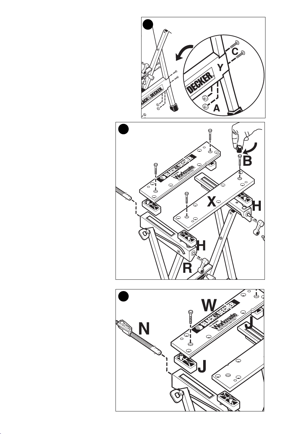
STEP 5:
• Place the front bracket (Y) over the legs,
align holes and secure with Pan Head
bolt, M6 x 30mm (C) and M6 nut (A). Use
flat bladed screwdriver and nut driver (U)
to secure.
STEP 6:
• Place front slide blocks (H) onto
the leg assemblies (L) and (R)
as shown.
• Place vise jaw (X), V-groove
facing towards clamp edge, over
the two slide blocks (H).
• Insert two self-threading hex
head bolts (B), through the
recessed holes in the jaw and
tighten securely with nut driver
(U).
STEP 7:
• Insert non-threaded rod end of
pre-assembled vise screw and
pivot nut assembly (N) through
front hole of leg assembly (R).
Repeat with other pivot nut and
vise screw using front hole of
leg assembly (L). NOTE: Insure
pivot nut is threaded onto screw
about 1/4 of the way.
• Place the two rear slide blocks
(J) over pivot nuts of screw
assembly (N).
• Place the rear vise jaw (W),
V-groove facing towards clamp
edge, over the slide blocks (J).
• Insert two self-threading hex
head bolts (B), through the
recessed holes in the jaw and
tighten securely with nut driver (U).
5
B
R
L
7
6
90555796 WM125.qxd:??????-00 BDL500 laser 9/25/09 12:44 PM Page 4
Loading ...
Loading ...
Loading ...