Loading ...
Loading ...
Loading ...
31-5000500 Rev. 0 11
ENGLISH
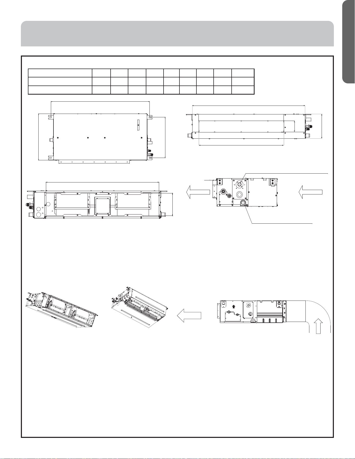
Dimensions and Service Clearances
Installation modes of Indoor unit
This series of air conditioners can be arranged in two air return modes:
1. Air return from the back (factory default).
2. Air return from the bottom (can be adjusted on site). See the following figures.
Note: The downward air return mode will increase noise 3-5dB(A). It is recommended to install the air conditioner in
downward return air mode (figure 2) if enough space is available.
Installation space and method
Body installation
1. Use 3/8” (M10) all-thread rod.
2. Ceiling removal: Please consult with an engineer about changes to the building structure.
a. Ceiling reinforcement: Ensure the ceiling is stable and will not shake. The ceiling base frame must be reinforced.
b. Cut off and remove the ceiling base frame.
c. Reinforce the faces left when the ceiling is removed and further reinforce the base frame that fix both ends of the ceiling.
d. Install piping and wiring after the indoor unit installation is complete. Before installation, choose a suitable installation
position and determine the outgoing direction of pipes. Especially in case that a ceiling exists, please pull refrigerant
tubing, drain hoses, and wiring to their positions prior to actually hanging the indoor unit.
INSTALLATION INSTRUCTIONS
Model A B C D E F G H I
MVAD007~12MV2AA 16.5 35.1 14.6 33.5 7.3 25.2 3.6 29.9 6.0
MVAD018~24MV2AA 16.5 47.7 14.6 46.1 7.3 37.8 3.6 42.5 6.0
a
b
c
Hanger dimensions
Dimensions of return air inlet
h
i
Dimensions of pump drainage
hole, OD 1"
Dimensions of natural
drainage hole, OD 1"
Dimensions of drain hose
Air out
30
Air in
g
d
f
e
Dimension of air outlet
Air return from the back
Figure 1
AIR
Air return from the bottom 1
Figure 2
UP
Air out
Air in
Air return from the bottom 2
Figure 3
Loading ...
Loading ...
Loading ...