User Manual
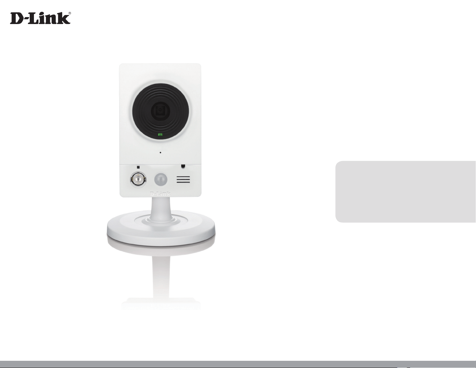
HD Wireless N Cube Network Camera
Version 1.0 | 13 /06/2012
DCS-2132L
2D-Link DCS-2132L User Manual
D-Link reserves the right to revise this publication and to make changes in the content hereof without obligation to notify any person or
organization of such revisions or changes. Information in this document may become obsolete as our services and websites develop and
change. Please refer to the www.mydlink.com website for the most current information.
Manual Revisions
Revision Date Description
1.0 May 25, 2012 DCS-2132L Revision A1 with rmware version 1.00
Trademarks
D-Link and the D-Link logo are trademarks or registered trademarks of D-Link Corporation or its subsidiaries in the United States or other
countries. All other company or product names mentioned herein are trademarks or registered trademarks of their respective companies.
Copyright © 2012 D-Link Corporation.
All rights reserved. This publication may not be reproduced, in whole or in part, without prior expressed written permission from D-Link Corporation.
Preface

3D-Link DCS-2132L User Manual
Table of Contents
Product Overview ......................................................................... 5
Package Contents ................................................................. 5
Introduction ............................................................................6
System Requirements ......................................................... 6
Features ....................................................................................7
Hardware Overview ............................................................. 8
Front ...................................................................................... 8
Rear ........................................................................................ 9
Sides ....................................................................................10
Installation ....................................................................................11
Wireless Installation Considerations ............................11
Zero Conguration Setup ................................................12
Camera Installation Wizard .............................................16
Manual Hardware Installation ........................................24
WPS - Push Button Setup .................................................25
mydlink ...........................................................................................26
Camera Status ......................................................................27
Live Video ..............................................................................28
Playback .................................................................................29
Settings ..................................................................................30
Recording Settings .........................................................31
Advanced Settings .........................................................33
Events ......................................................................................34
Conguration ...............................................................................35
Using the Conguration Interface ................................35
Live Video ..............................................................................36
Setup .......................................................................................38
Setup Wizard ....................................................................38
Network Setup .................................................................44
Wireless Setup ..................................................................47
Dynamic DNS ...................................................................48
Image Setup .....................................................................49
Audio and Video ..............................................................51
Preset ...................................................................................53
Motion Detection ...........................................................55
Time and Date ..................................................................56
Event Setup .......................................................................57
SD Card ...............................................................................66
Advanced ...............................................................................67
Digital Input/Output ......................................................67
ICR and IR ...........................................................................68
HTTPS ..................................................................................69
Access List ..........................................................................70
Maintenance .........................................................................71
Device Management .....................................................71
System ................................................................................72
Firmware Upgrade ..........................................................73
Status ......................................................................................74
Device Info ........................................................................74
Logs .....................................................................................75

4D-Link DCS-2132L User Manual
Help......................................................................................76
DI/DO Specications .................................................................77
Technical Specications ...........................................................78
Safety Statements ......................................................................81
5D-Link DCS-2132L User Manual
Section 1: Product Overview
Product Overview
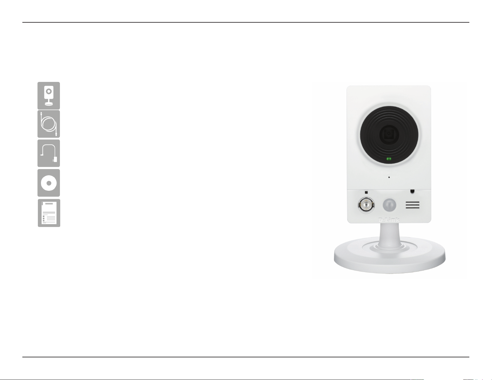
Package Contents
If any of the above items are missing, please contact your reseller.
Note: Using a power supply with a dierent voltage than the one included with your
product will cause damage and void the warranty for this product.
DCS-2132L HD Wireless N Cube Network Camera
CAT5 Ethernet cable
Power adapter
CD-ROM with User Manual and software
Quick Installation Guide

6D-Link DCS-2132L User Manual
Section 1: Product Overview
Introduction
Congratulations on your purchase of the DCS-2132L HD Wireless N Cube Network Camera. The DCS-2132L is a versatile and
unique solution for your small oce or home. Unlike a standard webcam, the DCS-2132L is a complete system with a built-in
CPU and web server that transmits high quality video images for security and surveillance. The DCS-2132L can be accessed
remotely, and controlled from any PC/Notebook over your local network or through the Internet via a web browser. The simple
installation and intuitive web-based interface oer easy integration with your Ethernet/Fast Ethernet or 802.11n/g wireless
network. The DCS-2132L also comes with remote monitoring and motion detection features for a complete and cost-eective
home security solution.
• Computer with Microsoft Windows® 7, Vista®, or XP (for CD-ROM Setup Wizard), Mac OS or Linux
• PC with 1.3GHz or above; at least 128MB RAM
• Internet Explorer 7 or above , Firefox 3.5 or above, Safari 4 and Chrome 8.0 or above
• Existing 10/100 Ethernet-based network or 802.11n wireless network
• A MicroSD memory card (optional) is required to record streaming video. SDHC Class 6 or above is recommended.
System Requirements

7D-Link DCS-2132L User Manual
Section 1: Product Overview
Simple to Use
The DCS-2132L is a stand-alone system with a built-in CPU, requiring no special hardware or software. The DCS-2132L supports both ActiveX mode
for Internet Explorer and Java mode for other browsers such as Firefox® and Safari®.
Supports a Variety of Platforms
Supporting TCP/IP networking, HTTP, and other Internet related protocols. The DCS-2132L can also be integrated easily into other Internet/Intranet
applications because of its standards-based features.
802.11n Wireless or Ethernet/Fast Ethernet Support
The DCS-2132L oers wireless 802.11n and Ethernet/Fast Ethernet connectivity, making the DCS-2132L easy to integrate into your existing
network environment. The DCS-2132L works with a 10Mbps Ethernet based network or 100Mbps Fast Ethernet based network for traditional wired
environments, and works with 802.11n routers or access points for added exibility. The Site Survey feature also allows you to view and connect to
any available wireless networks.
Web Conguration
Using a standard Web browser, administrators can congure and manage the Network Camera directly from its own Web page via Intranet or
Internet. This means you can access your DCS-2132L anytime, anywhere in the world.
Broad Range of Applications
With today’s high-speed Internet services, the Network Camera can provide the ideal solution for delivering live video images over the Intranet and
Internet for remote monitoring. The Network Camera allows remote access using a Web browser for live image viewing, and allows the administrator
to manage and control the Network Camera anytime, anywhere in the world. Many applications exist, including industrial and public monitoring
of homes, oces, banks, hospitals, child-care centers, and amusement parks.
Remote Monitoring Utility
The D-ViewCam application adds enhanced features and functionality for the Network Camera and allows administrators to congure and access
the Network Camera from a remote site via Intranet or Internet. Other features include image monitoring, recording images to a hard drive, viewing
up to 32 cameras on one screen, and taking snapshots.
IR LED for Day and night functionality
The built-in infrared LEDs enables night time viewing of up to 16 feet (5 meters).
Features
8D-Link DCS-2132L User Manual
Section 1: Product Overview
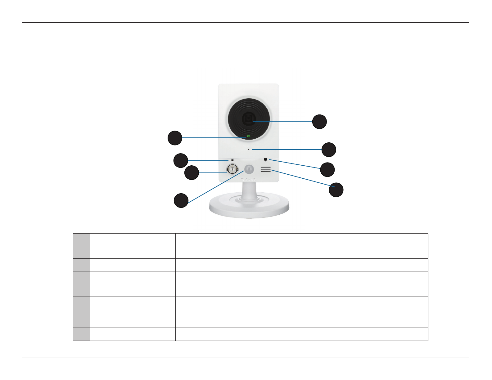
Front
Hardware Overview
1 Status LED
Indicates the camera's current status
2 WPS Status LED Indicates the WPS connection status of the camera
3 Infrared LED
Used to illuminate the camera's eld of view at night
4 PIR Sensor
Passive Infrared sensor for motion detection
5 Camera Lens Records video of the surrounding area
6 Microphone Records audio from the surrounding area
7
ICR Sensor
The IR-Cut Removable sensor monitors lighting conditions and switches between
color and infrared accordingly
8
Speaker
Audio output
1
2
3
4
5
6
8
7
9D-Link DCS-2132L User Manual
Section 1: Product Overview
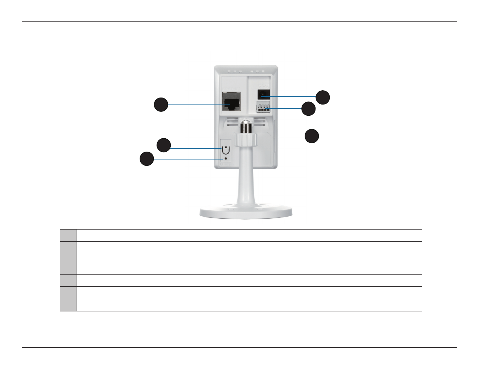
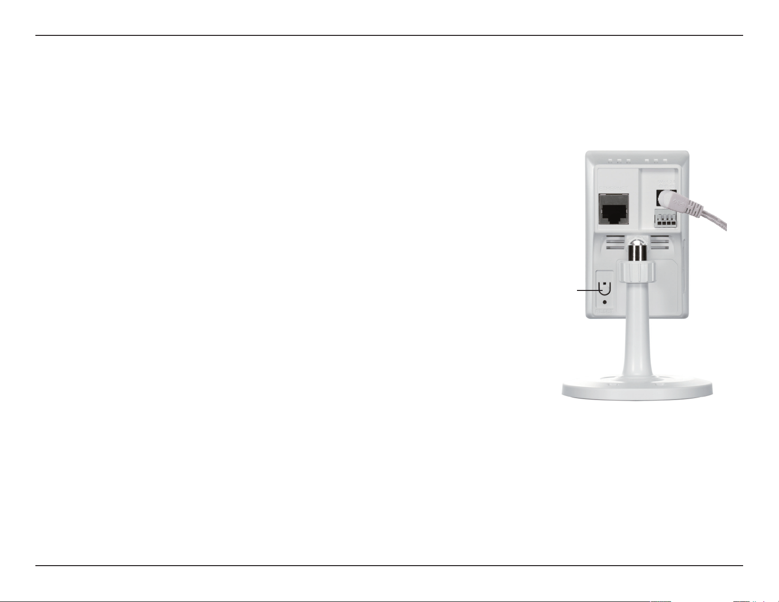
Rear
1 Ethernet Port
RJ45 connector for Ethernet
2 WPS Button
Press this button, then press the WPS button for 5 seconds on your router to set up
a wireless connection automatically
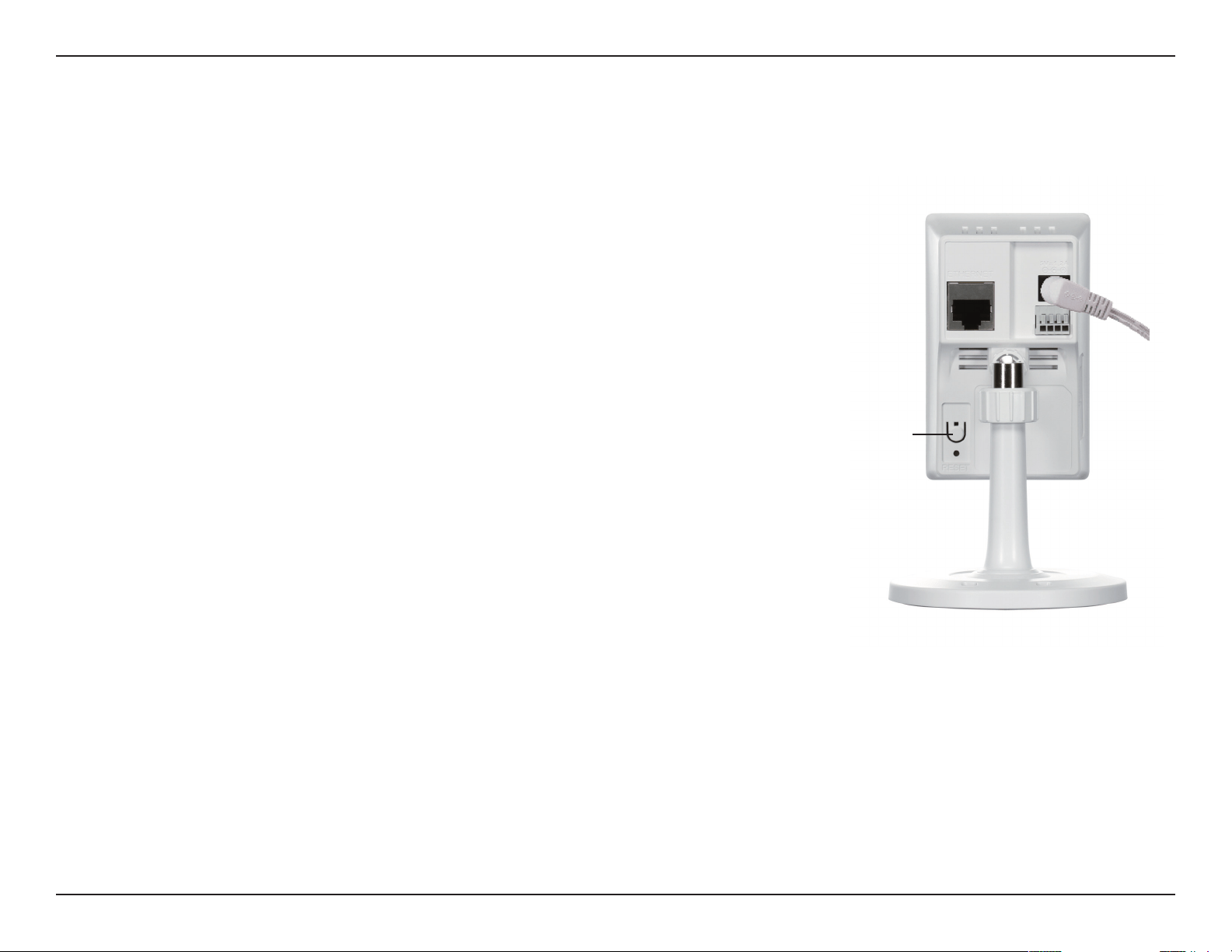
3 Reset Button
Press and hold this button for 10 seconds to reset the camera
4 Power Connector
Connects to the included DC 5 V power adapter
5 DI/DO Connector
I/O connectors for external devices
6 Adjustment Ring Tighten or loosen the adjustment ring to adjust the camera's position
1
3
4
5
6
2
10D-Link DCS-2132L User Manual
Section 1: Product Overview
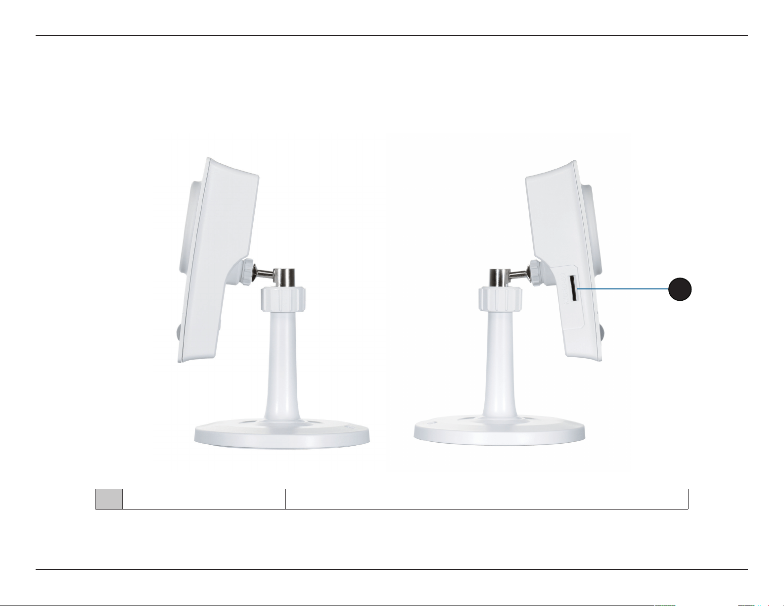
Sides
1 Micro SD Card Slot
Insert a MicroSD card for Local storage for storing recorded image and video
1

11D-Link DCS-2132L User Manual
Section 2: Installation
This D-Link device can connect to your wireless network from anywhere within the operating range of your wireless network. However, the number,
thickness and location of walls, ceilings, or other objects that the wireless signals must pass through, may limit the range. Typical ranges vary
depending on the types of materials and background RF (radio frequency) noise in your home or business. The key to maximizing wireless range
is to follow these basic guidelines:
1. Minimize the number of walls and ceilings between your adapter and other network devices (such as your Network Camera) - each wall or
ceiling can reduce your adapter’s range from 3-90 feet (1-30 meters).
2. Be aware of the direct line between network devices. A wall that is 1.5 feet thick (.5 meters), at a 45-degree angle appears to be almost 3 feet
(1 meter) thick. At a 2-degree angle, it looks over 42 feet (14 meters) thick. Position your devices so that the signal will travel straight through
a wall or ceiling (instead of at an angle) for better reception.
3. Building Materials make a dierence. A solid metal door or aluminum studs may weaken the wireless signal. Try to position your access points,
wireless routers, and other networking devices where the signal passes through drywall or open doorways. Materials and objects such as
glass, steel, metal, walls with insulation, water (sh tanks), mirrors, le cabinets, brick, and concrete will degrade your wireless signal.
4. Keep your product at least 3-6 feet or 1-2 meters away from electrical devices or appliances that generate RF noise.
5. If you are using 2.4GHz cordless phones or other radio frequency sources (such as microwave ovens), your wireless connection may degrade
dramatically or drop completely. Make sure your 2.4GHz phone base is as far away from your wireless devices as possible. The base transmits
a signal even if the phone in not in use.
Installation
Wireless Installation Considerations

12D-Link DCS-2132L User Manual
Section 2: Installation
Zero Conguration Setup
If you have a D-Link Cloud Router, you can take advantage of Zero Conguration. Zero Conguration automatically congures
your camera's settings for you, and adds it to your mydlink account automatically. This type of setup allows you to set up your
camera by simply plugging it in and connecting it to your router.
Connect your camera to your mydlink enabled cloud router and Zero Conguration will automatically congure your
DCS-2132L and automatically add the camera to your mydlink account. You can now remotely access your camera from the
mydlink.com website to manage and monitor your DCS-2132L.
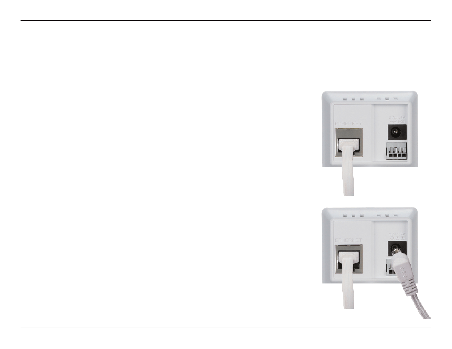
Connect the Ethernet Cable
If using an Ethernet connection: Connect the included Ethernet cable to the
Ethernet port located on the back of the DCS-2132L and connect it to your router.
Attach the External Power Supply
Attach the external power supply to the DC Power receptor located on the rear
panel of the DCS-2132L and connect it to your wall outlet or power strip.
13D-Link DCS-2132L User Manual
Section 2: Installation
To create a WPS connection:
Step 1
Press and hold the WPS button for approximately 5-6 seconds. The blue WPS
status LED above the button will blink.
Step 2
Within 60 seconds press the WPS button on your router. On some routers, you
may need to log in to the web interface and click on an on-screen button to
activate the WPS feature. If you are not sure where the WPS button is on your
router, please refer to your router’s User Manual.
The DCS-2132L will automatically create a wireless connection to your router.
While connecting, the status LED will ash. When the connection process is
complete, the status LED will turn solid.
Note: If your router does not support WPS, you can still use the wired connection
method on the previous page. After Zero Conguration setup is complete, your
router's wireless settings will be automatically transferred to the camera.
Optional: WPS Wireless Connection
Alternatively, if your router supports WPS, you can use the WPS button on the
camera to easily create a secure wireless connection to your network.
WPS Button

14D-Link DCS-2132L User Manual
Section 2: Installation
A summary and conrmation notication will appear with the automatically
congured details. Make a note of the details and click OK to add the camera to
your account.
Check Your mydlink Account
From any computer, open a web browser, go to http://www.mydlink.com and log
into your account. Once mydlink detects your camera, a New Device Found!
notice will appear in the bottom-left corner. Click on the device name to continue.

15D-Link DCS-2132L User Manual
Section 2: Installation
Zero Conguration is now complete and your camera has been added to your
mydlink account. You can now view your camera on the mydlink Live View tab.
If you wish to connect your camera to your router wirelessly, you can simply
disconnect the Ethernet cable and move the camera to its intended location; your
router's wireless settings have been automatically transferred to the camera, and
no further conguration is required.
Your camera is now set up, and you can skip to "mydlink" on page 26 to learn more
about the mydlink features of this camera, or to "Conguration" on page 35 for
advanced conguration of your camera.
16D-Link DCS-2132L User Manual
Section 2: Installation
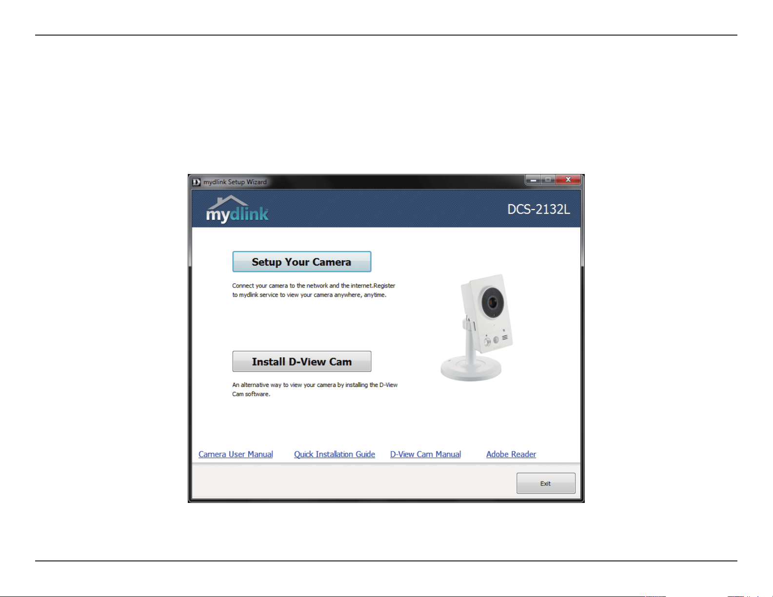
Insert the Installation CD-ROM into your computer’s optical drive to start the autorun program.
The CD-ROM will open the Camera Installation Wizard. Simply click Setup Your Camera to go through the Installation Wizard,
which will guide you through the installation process from connecting your hardware to conguring your camera.
Camera Installation Wizard
17D-Link DCS-2132L User Manual
Section 2: Installation
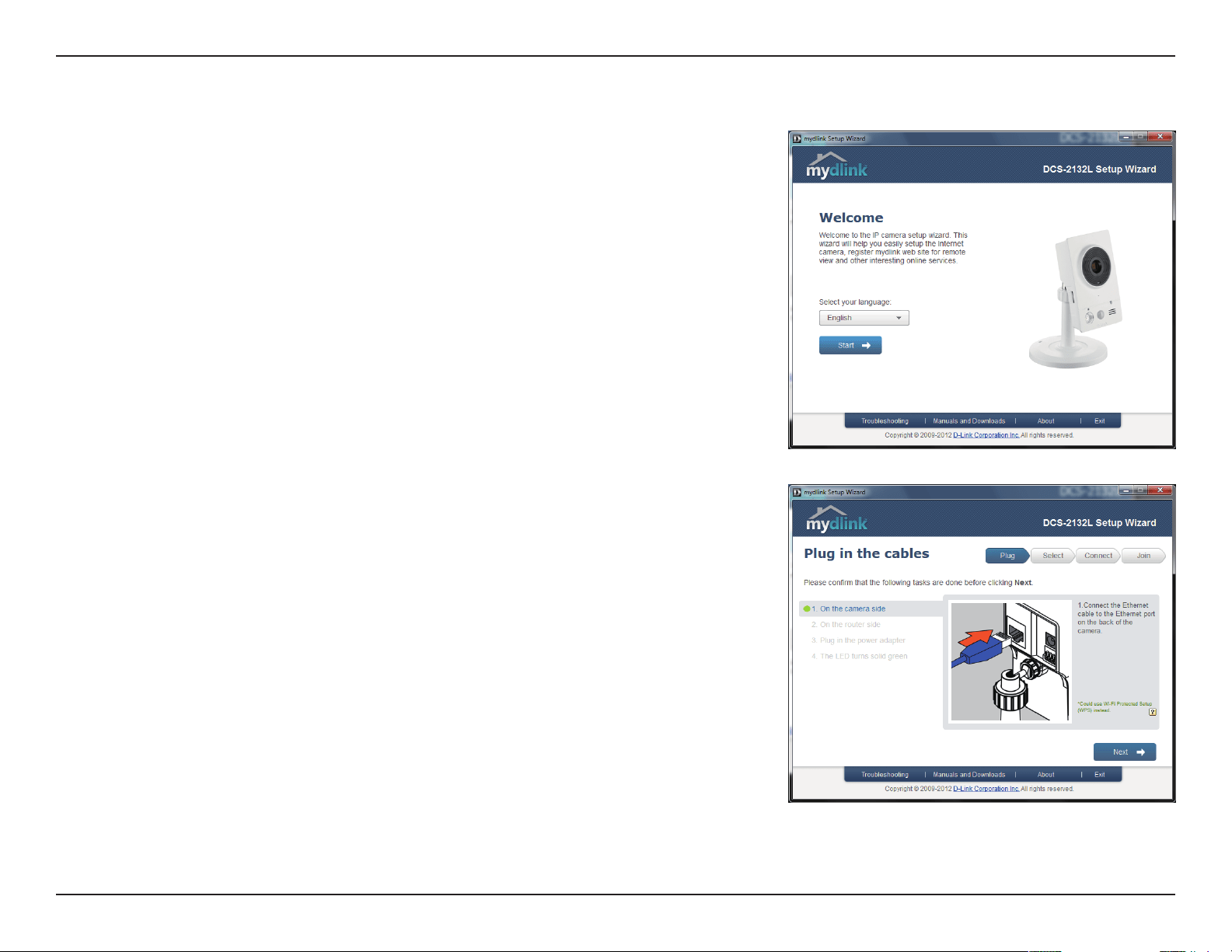
Connect the included Ethernet cable to the network cable connector located on
the panel at the rear of the DCS-2132L and attach it to the network.
Click Next to continue.
Select your preferred language for the installation from the drop down menu
and click on Start to continue.
18D-Link DCS-2132L User Manual
Section 2: Installation
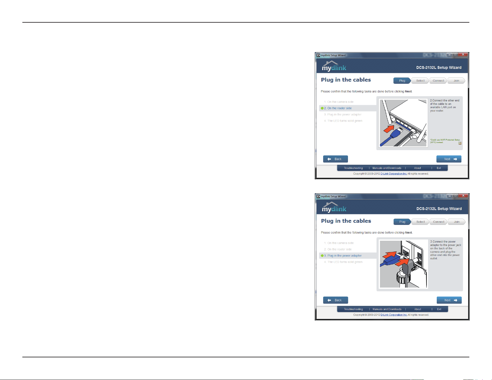
Connect the other end of the same Ethernet cable to a router.
Click Next to continue.
Attach the external power supply to the power connector located on the rear
panel of the DCS-2132L and connect it to your wall outlet or power strip.
Click Next to continue.
19D-Link DCS-2132L User Manual
Section 2: Installation
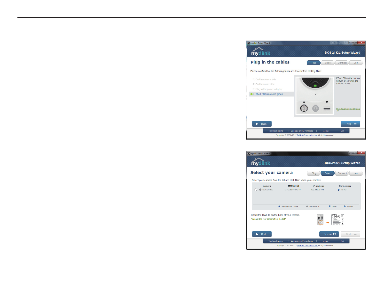
The LED on the front of the DCS-2132L will blink, then turn solid green once it
successfully connects to your network. Click Next to proceed.
If the LED continues to blink, check your connections or click on the "What should
I do if the LED stays red?" link for more information.
Select your camera from the list, then click Next. If you have multiple cameras, you
can identify them by the MAC ID printed on the label on the back of your camera.
20D-Link DCS-2132L User Manual
Section 2: Installation
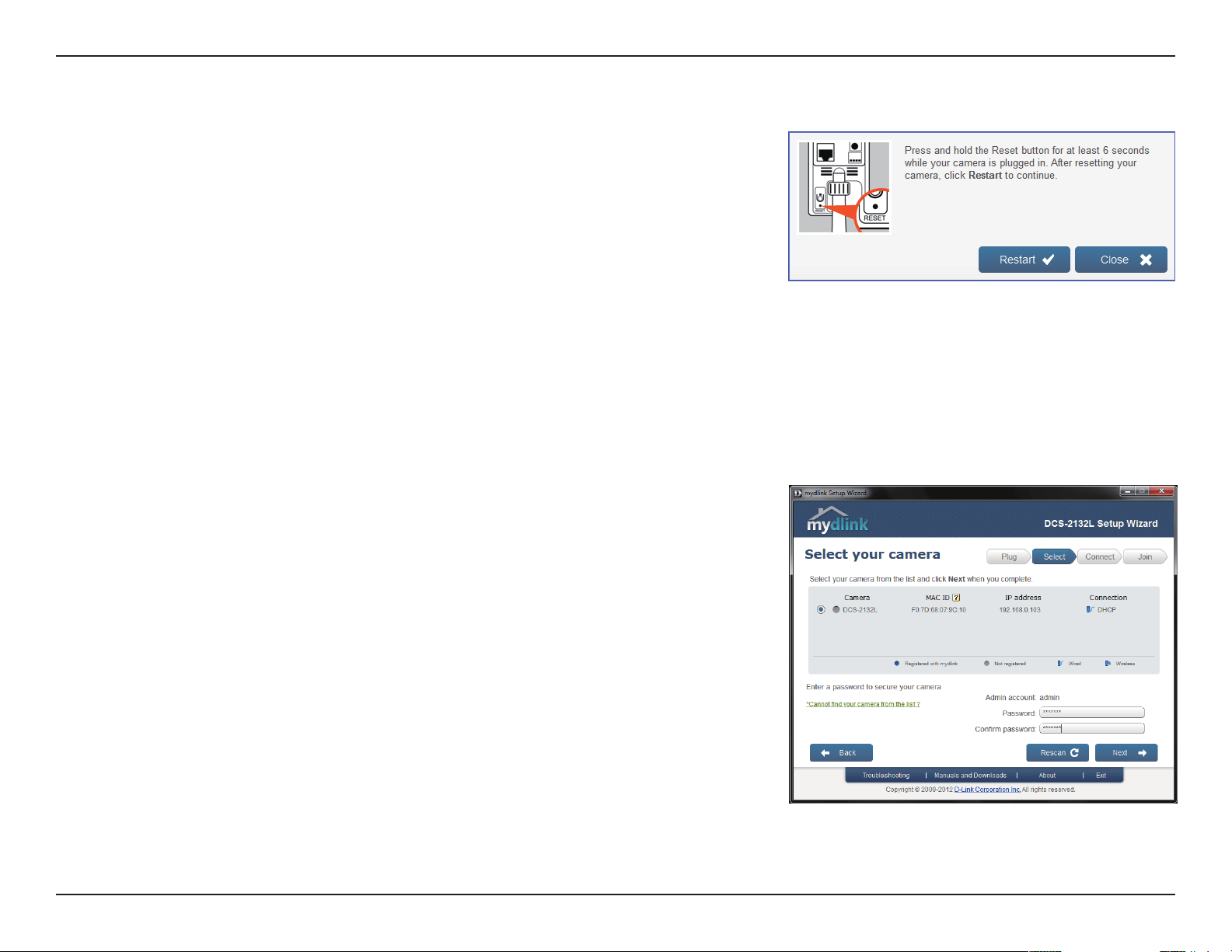
If you wish to remove the camera from a previously registered mydlink account,
press and hold the reset button on the rear panel for at least 6 seconds and click
Restart to restart the wizard.
After you have selected your camera from the list, you will be asked to create
and conrm a password for it. The password is case sensitive and must contain
at least 2 letters.
Click Next to continue.
21D-Link DCS-2132L User Manual
Section 2: Installation
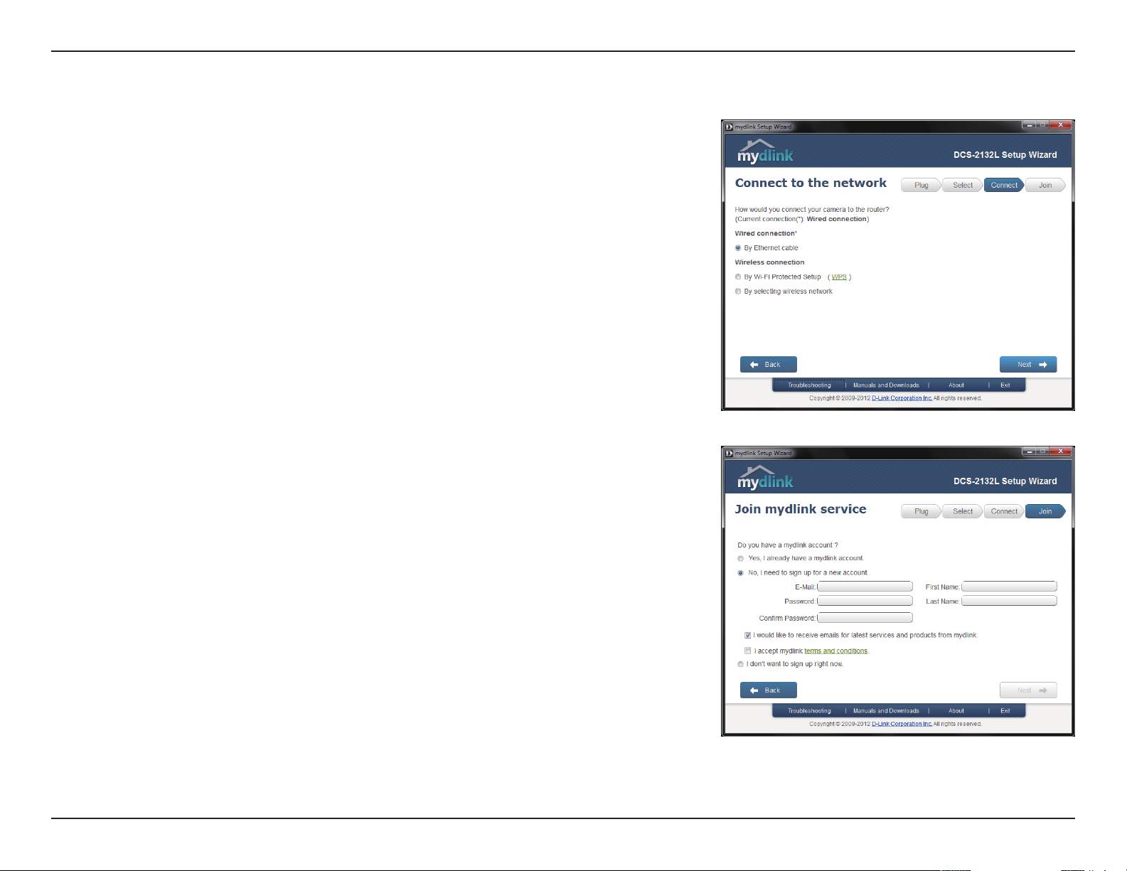
To move the camera to a wireless connection by using WPS or by selecting a
wireless network, select the appropriate option then follow the steps displayed.
Otherwise, click Next to continue.
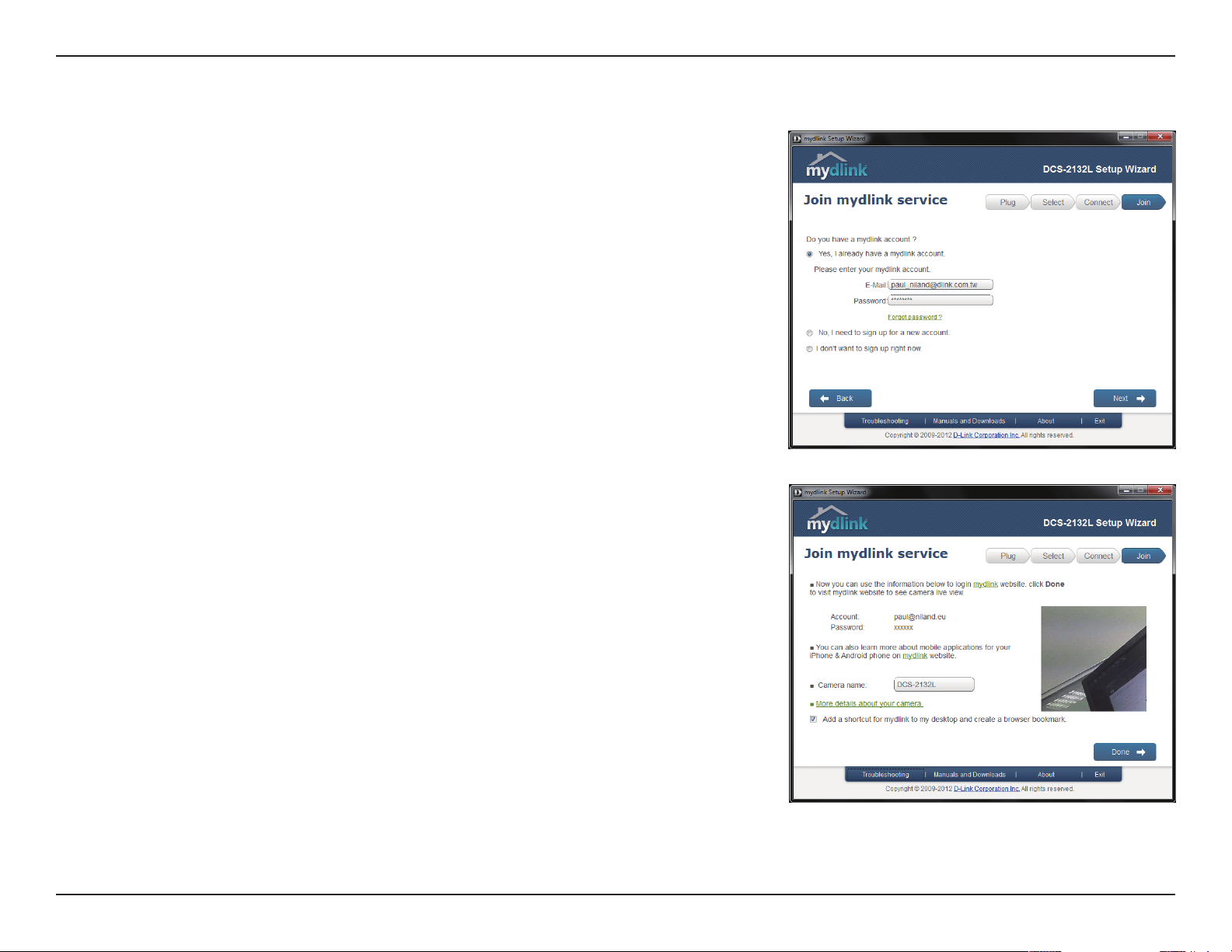
Complete the mydlink account registration form with your details making sure to
select the I accept mydlink terms and conditions box, and click the Next button.
22D-Link DCS-2132L User Manual
Section 2: Installation
If you already have a mydlink account, enter your login details and click Next to
proceed.
Conrm your mydlink account details and give the camera a unique name and
click Done.
23D-Link DCS-2132L User Manual
Section 2: Installation
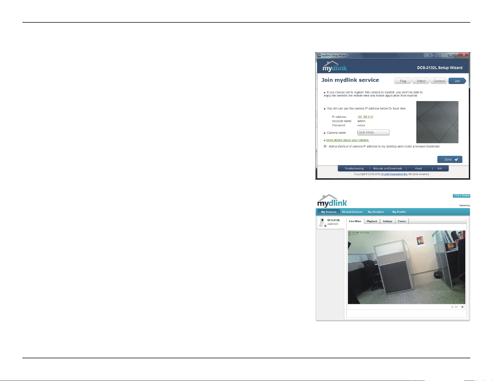
Conrm your camera login details and IP address details and click Done.
Your DCS-2132L camera is now set up. Log on to your mydlink account and
explore the exciting benets available to you.
Your camera is now set up, and you can skip to "mydlink" on page 26 to learn more
about the mydlink features of this camera, or to "Conguration" on page 35 for
advanced conguration of your camera.
24D-Link DCS-2132L User Manual
Section 2: Installation
Connect the Ethernet Cable
Connect the included Ethernet cable to the network cable connector located on
the panel at the rear of the DCS-2132L and attach it to the network.
Attach the External Power Supply
Attach the external power supply to the DC Power receptor located on the rear
panel of the DCS-2132L and connect it to your wall outlet or power strip.
Manual Hardware Installation
If you wish to set up your camera without using the Camera Setup Wizard, please follow these steps.
Note: In order to use the mydlink features of this product, you will need to go through the Camera Setup Wizard.
25D-Link DCS-2132L User Manual
Section 2: Installation
To create a WPS connection:
Step 1
Press and hold the WPS button for approximately 5-6 seconds. The blue WPS
status LED above the button will blink.
Step 2
Within 60 seconds press the WPS button on your router. On some routers, you
may need to log in to the web interface and click on an on-screen button to
activate the WPS feature. If you are not sure where the WPS button is on your
router, please refer to your router’s User Manual.
The DCS-2132L will automatically create a wireless connection to your router.
While connecting, the status LED will ash. When the connection process is
complete, the status LED will turn solid.
WPS - Push Button Setup
WPS Button
If your router supports WPS, you can use the WPS button on the camera to easily create a secure wireless connection to your
network.
26D-Link DCS-2132L User Manual
Section 3: mydlink
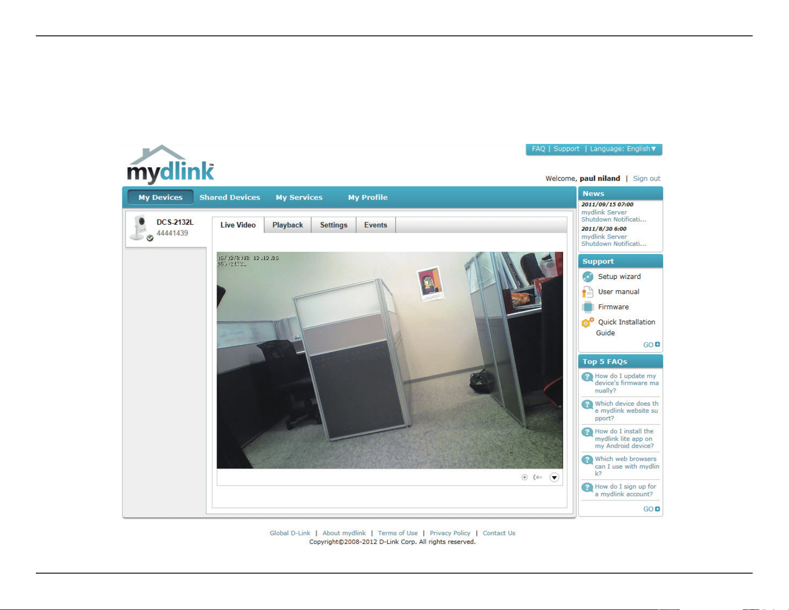
mydlink
After registering your DCS-2132L camera with a mydlink account in the Camera Installation Wizard. You will be able to remotely
access your camera from the www.mydlink.com website. After signing in to your mydlink account, you will see a screen similar
to the following:
27D-Link DCS-2132L User Manual
Section 3: mydlink
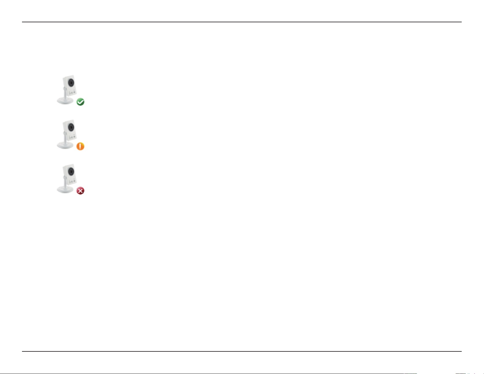
Camera Status
If your camera is oine, try the following:
• Check to make sure that the Internet connection to your camera is working properly.
• Try restarting your Internet router.
• Check your camera’s cable connections and make sure they are secure.
• Check to make sure that the LED on your camera is lit solid green.
If you still cannot access your camera, reset your camera and run the Camera Installation Wizard again from the CD-ROM
included in your package.
Here, you can see the online status of each of your cameras. Your online status may be one of the following:
A red X indicates that your camera is oine and currently cannot be accessed remotely.
A green checkmark indicates that your camera is online and ready to use.
A yellow exclamation point indicates that your camera is online, but the camera password
has changed. You will need to enter your new camera password to access your camera
again.
28D-Link DCS-2132L User Manual
Section 3: mydlink
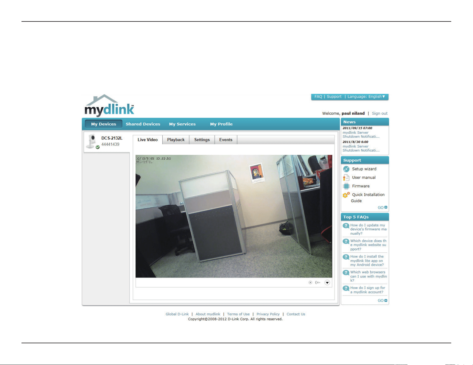
Live Video
In the main part of the screen, the Live Video tab will be selected by default. If the camera is available, a Live Video feed will be
displayed. Video will be shown at VGA resolution (640x480) if viewing your camera from a PC on the same local network, or at
QVGA resolution (320x240) if viewing your camera from a PC on a remote network.
29D-Link DCS-2132L User Manual
Section 3: mydlink
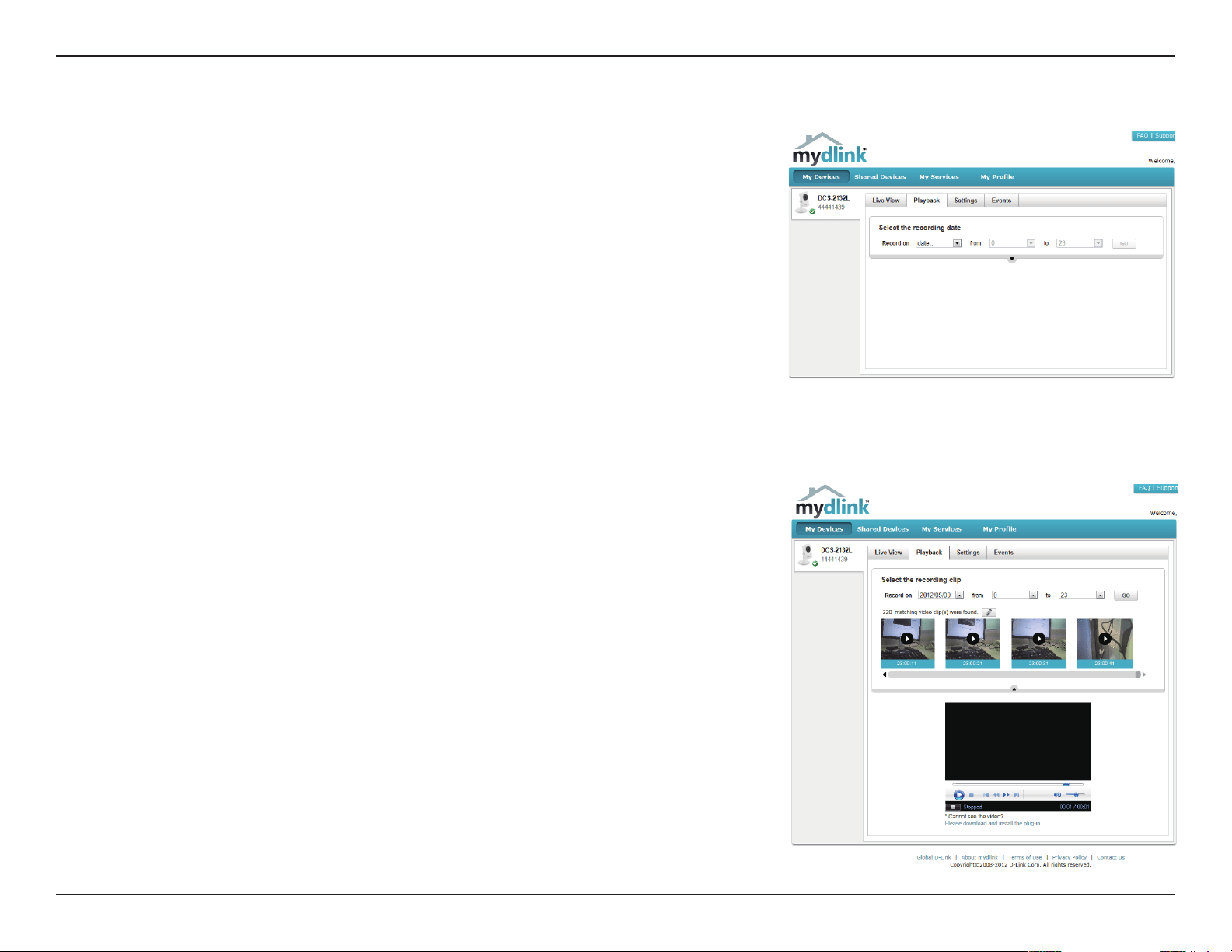
Playback
Select the date of the footage you wish to preview from the drop down menu,
then choose from the recordings available for playback.
The Playback tab allows you to review pre-recorded footage captured to an
inserted microSD card.
30D-Link DCS-2132L User Manual
Section 3: mydlink
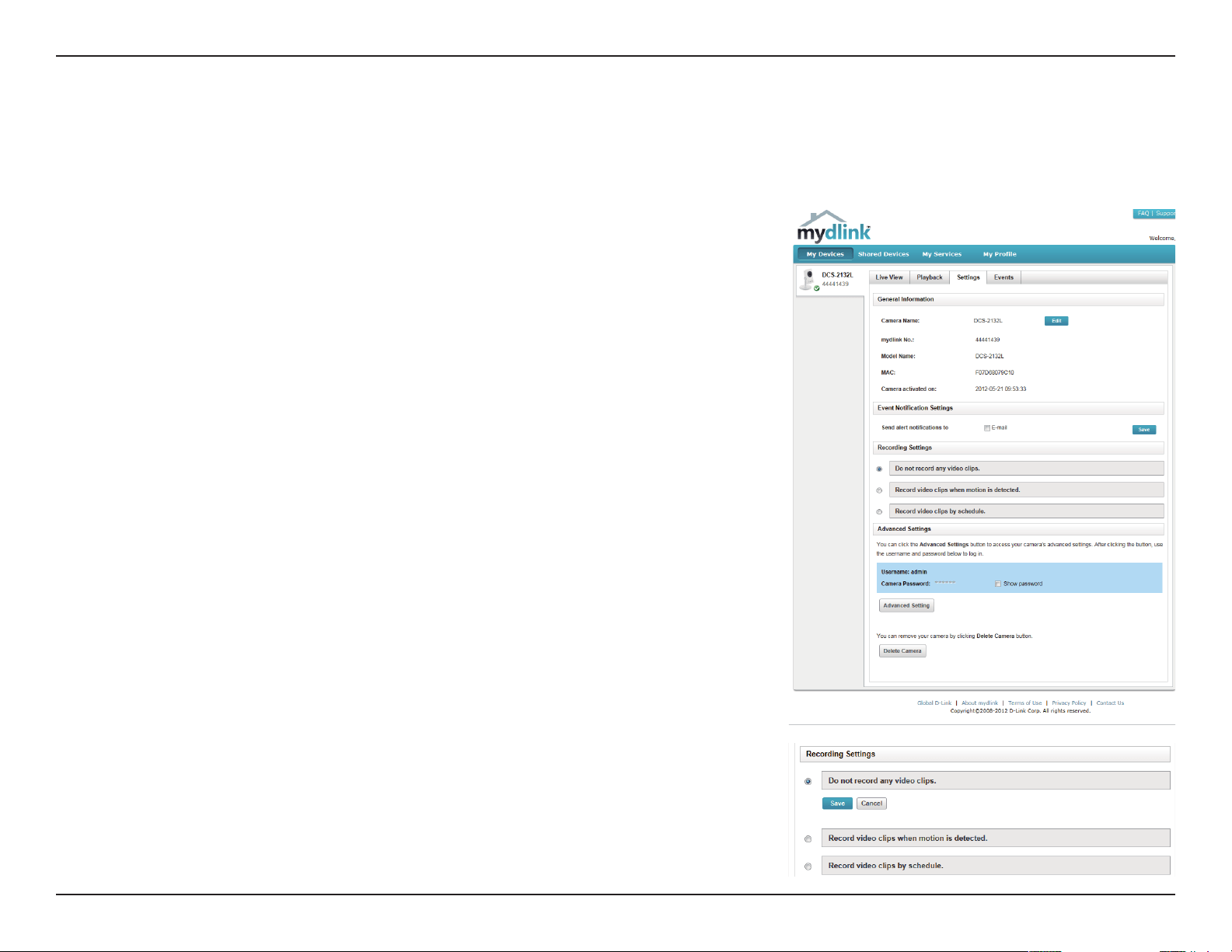
Settings
The Settings tab contains several options for you to control how your DCS-2132L
operates.
Click on the Edit button to change how the camera name appears.
This is the unique mydlink number for your device.
This shows the model name of the camera.
The shows the Media Access Control (MAC) address of the camera.
The date the camera was registered to the mydlink service.
Email notication of events can be switched on or o.
Camera Name:
mydlink No:
Model name:
MAC:
Camera Activated on:
Event Notication
Settings:
Each of the recording settings will open a further menu.Recording Settings:
31D-Link DCS-2132L User Manual
Section 3: mydlink
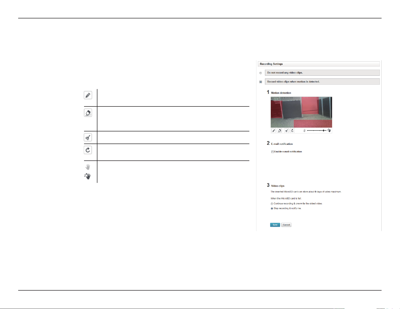
Select this option to enable the automatic recording when motion
is detected.
Add Detection Area: Click on this icon to draw areas that
will trigger automatic recording when motion is detected.
Remove Detection Area: Click on this icon to erase areas
from regions that trigger automatic recording when
motion is detected.
Clear Detection Area: This will remove all detection areas
Refresh Snapshot: This will refresh the current snapshot
of the monitored area.
Increase/Decrease Sensitivity Increase the motion
detection sensitivity
Toggles notication by email on or o.
In the event that the microSD card can not store further recordings,
the user can choose to record over previous recordings or to be
notied and cease recording.
Record video clips
when motion is
detected:
Email Notication:
Video Clips Recording
Mode:
Recording Settings
32D-Link DCS-2132L User Manual
Section 3: mydlink
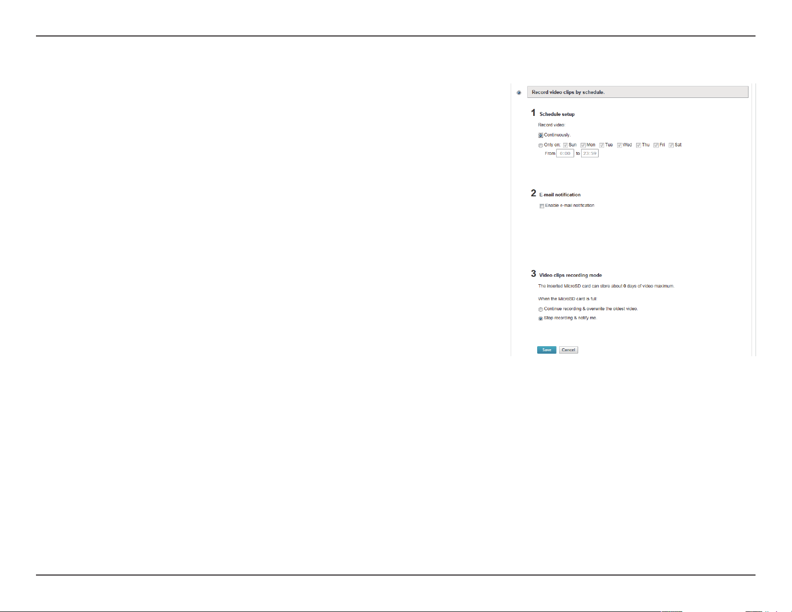
Toggles notication by email on or o.Email Notication:
This option enables either continuous or recurring scheduled
recording.
Record Video Clips by
Schedule:
In the event that the microSD card can not store further recordings,
the user can choose to record over previous recordings or to be
notied and cease recording.
Video Clips Recording
Mode:
33D-Link DCS-2132L User Manual
Section 3: mydlink
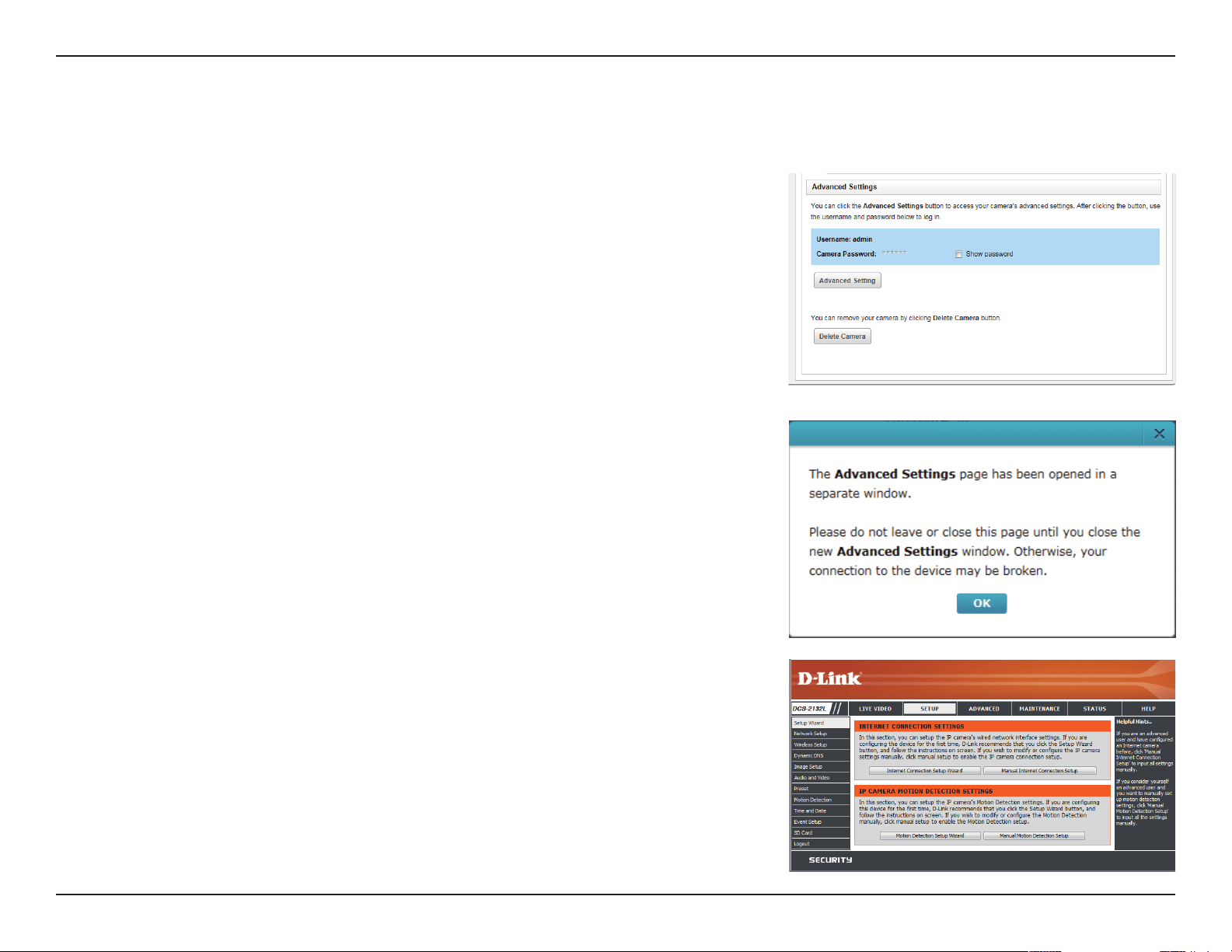
Checking this box will show the password.
Clicking on the Advanced Setting button will open a secondary
window allowing full conguration of the DCS-2132L
Show password:
Advanced Setting:
Advanced Settings
34D-Link DCS-2132L User Manual
Section 3: mydlink
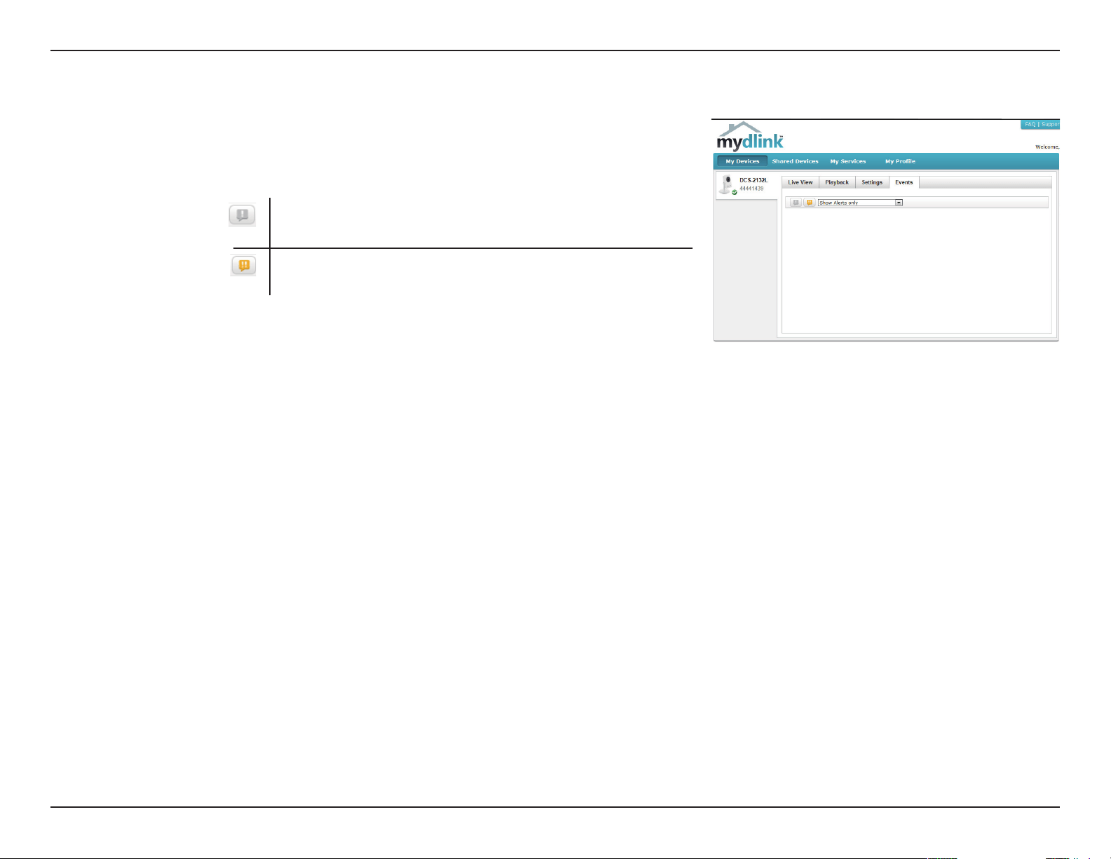
Events
Select this option to enable the automatic recording when motion
is detected.
Mark Page as Read: Clicking this button will mark the
current page of event notications as read.
Mark all as Read: Clicking this button will mark all event
notications as read.
Record video clips
when motion is
detected:
35D-Link DCS-2132L User Manual
Section 4: Conguration
Conguration
Using the Conguration Interface
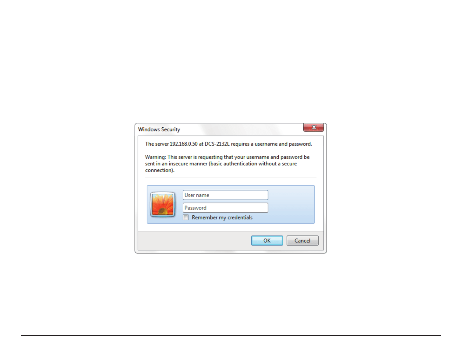
After completing the Camera Installation Wizard, you are ready to use your camera. The camera’s built-in Web conguration utility is designed to
allow you to easily access and congure your DCS-2132L. At the end of the wizard, click Go To Camera, or enter the IP address of your camera into
a web browser, such as Mozilla Firefox. To log in, use the User name admin and the password you created in the Installation Wizard. If you did not
create a password, the default password is blank. After entering your password, click OK.
36D-Link DCS-2132L User Manual
Section 4: Conguration
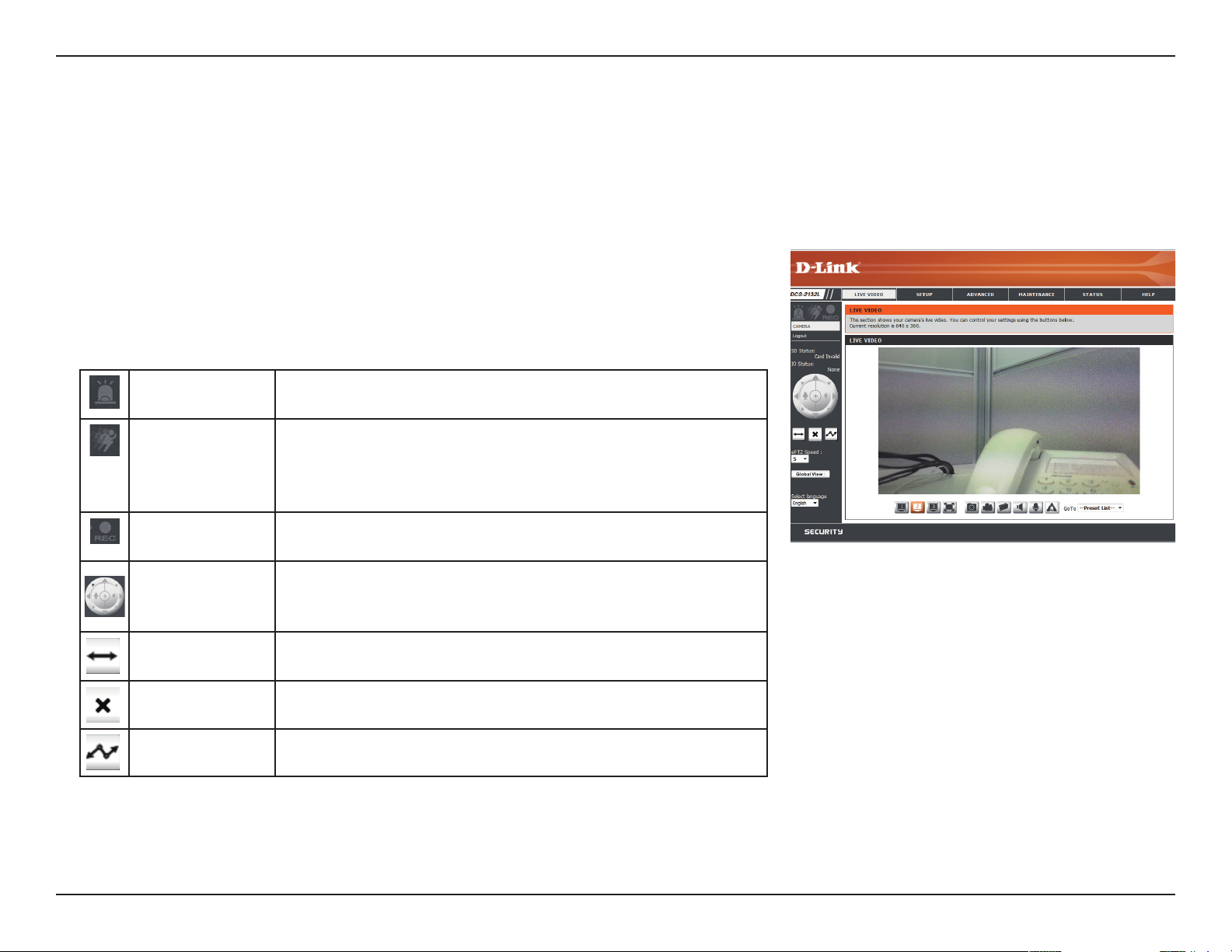
Live Video
This section shows your camera’s live video. You may select any of the available icons listed below to operate the camera. You may also select your
language using the drop-down menu on the left side of the screen.
You can zoom in and out on the live video image using your mouse. Right-click to zoom out or left-click to zoom in on the image.
Digital Input
Indicator
This indicator will change color when a digital input signal is
detected.
Motion Trigger
Indicator
This indicator will change color when a trigger event occurs.
Note: The video motion feature for your camera must be
enabled.
Recording
Indicator
When a recording is in progress, this indicator will change
color.
Control Pad
This control pad can be used to electronically pan, tilt, and
zoom (ePTZ) within the camera's predened view area, if one
has been dened.
Auto Pan Starts the automatic panning function. The ROI will pan from
back and forth within the FOV
Stop Stops automatic panning.
Preset Path Starts the camera's motion along the predened path.
You may select a value between 0 and 64. 0 is the slowest and 64 is the
fastest.
ePTZ Speed:
This option displays the status of the SD card. If no SD card has been
inserted, this screen will display the message "Card Invalid."
This option displays the status of your I/O device if a device has been
connected.
SD Status:
IO Status:
37D-Link DCS-2132L User Manual
Section 4: Conguration
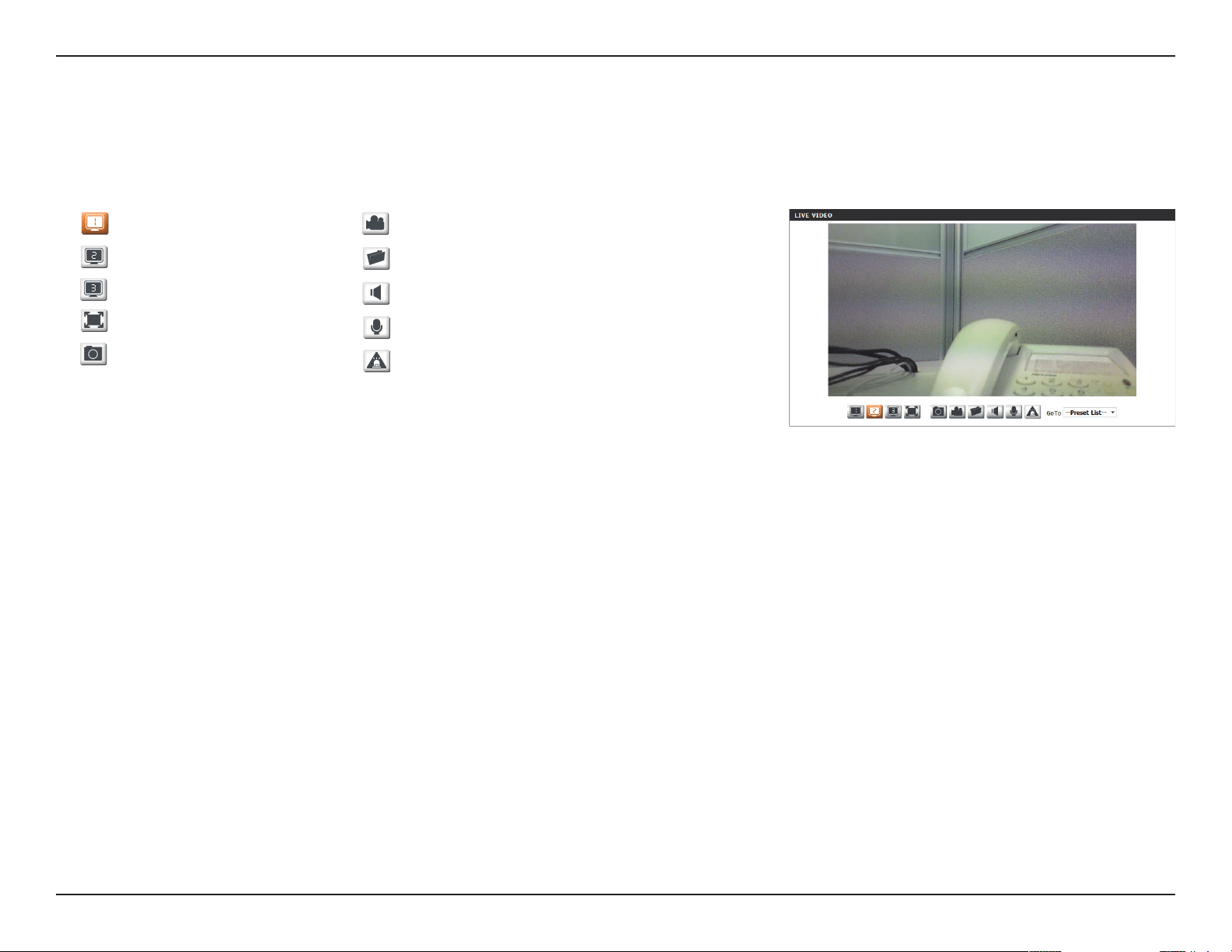
If any presets have been dened, selecting a preset from this list will
display it.
Go To:
(Preset List)
Video Prole 1
Video Prole 2
Video Prole 3
Full screen mode
Taking a Snapshot
Record a Video Clip
Set a Storage Folder
Listen/Stop Audio In (from microphone)
Start/Stop Audio Out (to speaker)
Start/Stop Digital Output
This window indicates the total eld of view (FOV) of the camera. The
red box indicates the visible region of interest (ROI).
You may select the interface language using this menu.
Global View:
Language:
38D-Link DCS-2132L User Manual
Section 4: Conguration
Setup
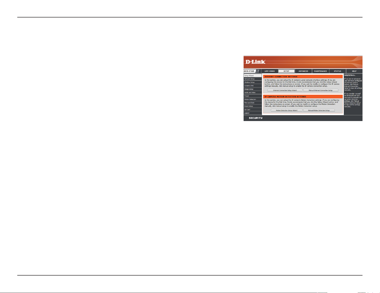
Setup Wizard
To congure your Network Camera, click Internet Connection Setup Wizard. Alternatively,
you may click Manual Internet Connection Setup to manually congure your Network
Camera and skip to "Network Setup" on page 44.
To quickly congure your Network Camera’s motion detection settings, click Motion
Detection Setup Wizard. If you want to enter your settings without running the wizard, click
Manual Motion Detection Setup and skip to"Motion Detection" on page 55.
39D-Link DCS-2132L User Manual
Section 4: Conguration
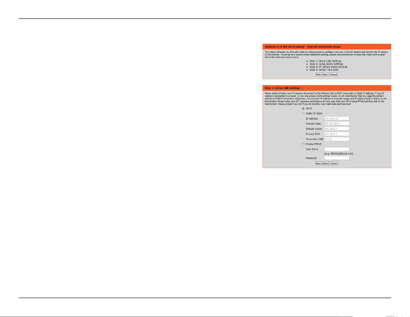
Internet Connection Setup Wizard
This wizard will guide you through a step-by-step process to congure your new D-Link
Camera and connect the camera to the internet. Click Next to continue.
Note: Select DHCP if you are unsure of which settings to choose.
Click Next to continue.
40D-Link DCS-2132L User Manual
Section 4: Conguration
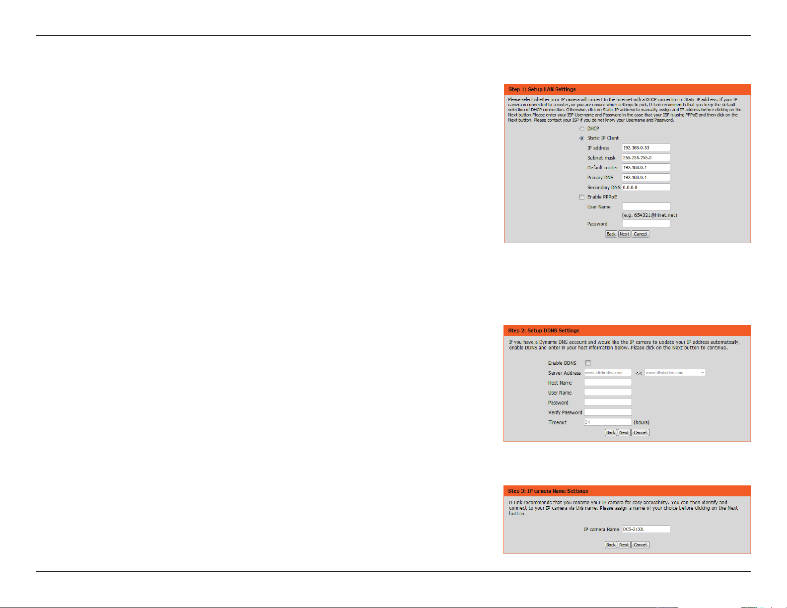
Select Static IP if your Internet Service Provider has provided you with connection settings, or
if you wish to set a static address within your home network. Enter the correct conguration
information and click Next to continue.
If you are using PPPoE, select Enable PPPoE and enter your user name and password,
otherwise click Next to continue.
If you have a Dynamic DNS account and would like the camera to update your IP address
automatically, Select Enable DDNS and enter your host information. Click Next to continue.
Enter a name for your camera and click Next to continue.
41D-Link DCS-2132L User Manual
Section 4: Conguration
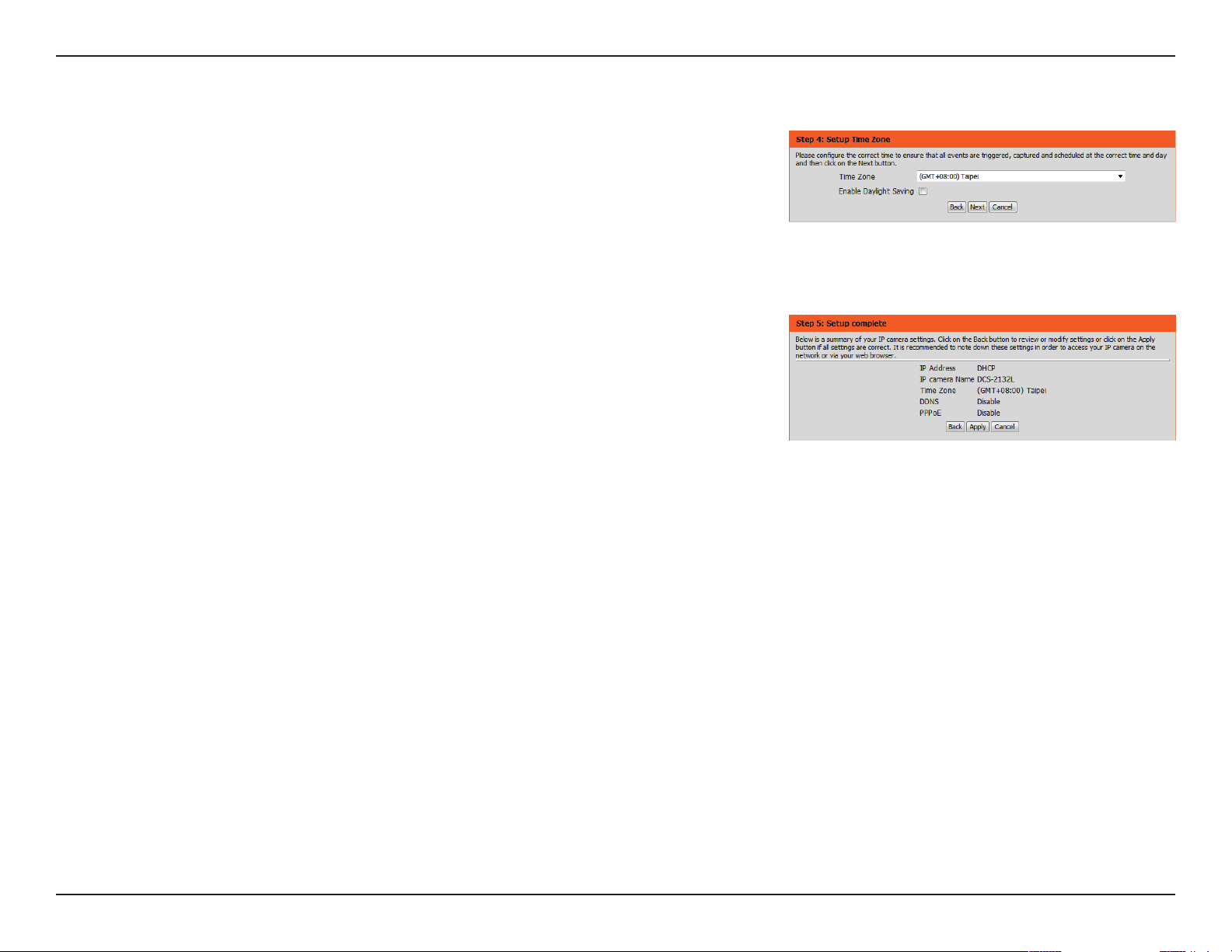
Congure the correct time to ensure that all events will be triggered as scheduled. Click Next
to continue.
If you have selected DHCP, you will see a summary of your settings, including the camera's IP
address. Please write down all of this information as you will need it in order to access your
camera.
Click Apply to save your settings.
42D-Link DCS-2132L User Manual
Section 4: Conguration
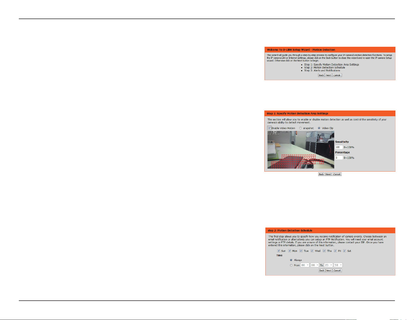
This wizard will guide you through a step-by-step process to congure your camera's
motion detection functions.
Click Next to continue.
Step 1
This step will allow you to enable or disable motion detection, specify the detection sensitivity,
and adjust the camera’s ability to detect movement.
You may specify whether the camera should capture a snapshot or a video clip when motion
is detected.
Please see the Motion Detection section on "Motion Detection" on page 55for information
about how to congure motion detection.
Step 2
This step allows you to enable motion detection based on a customized schedule. Specify the
day and hours. You may also choose to always record whenever motion is detected.
Motion Detection Setup Wizard
43D-Link DCS-2132L User Manual
Section 4: Conguration
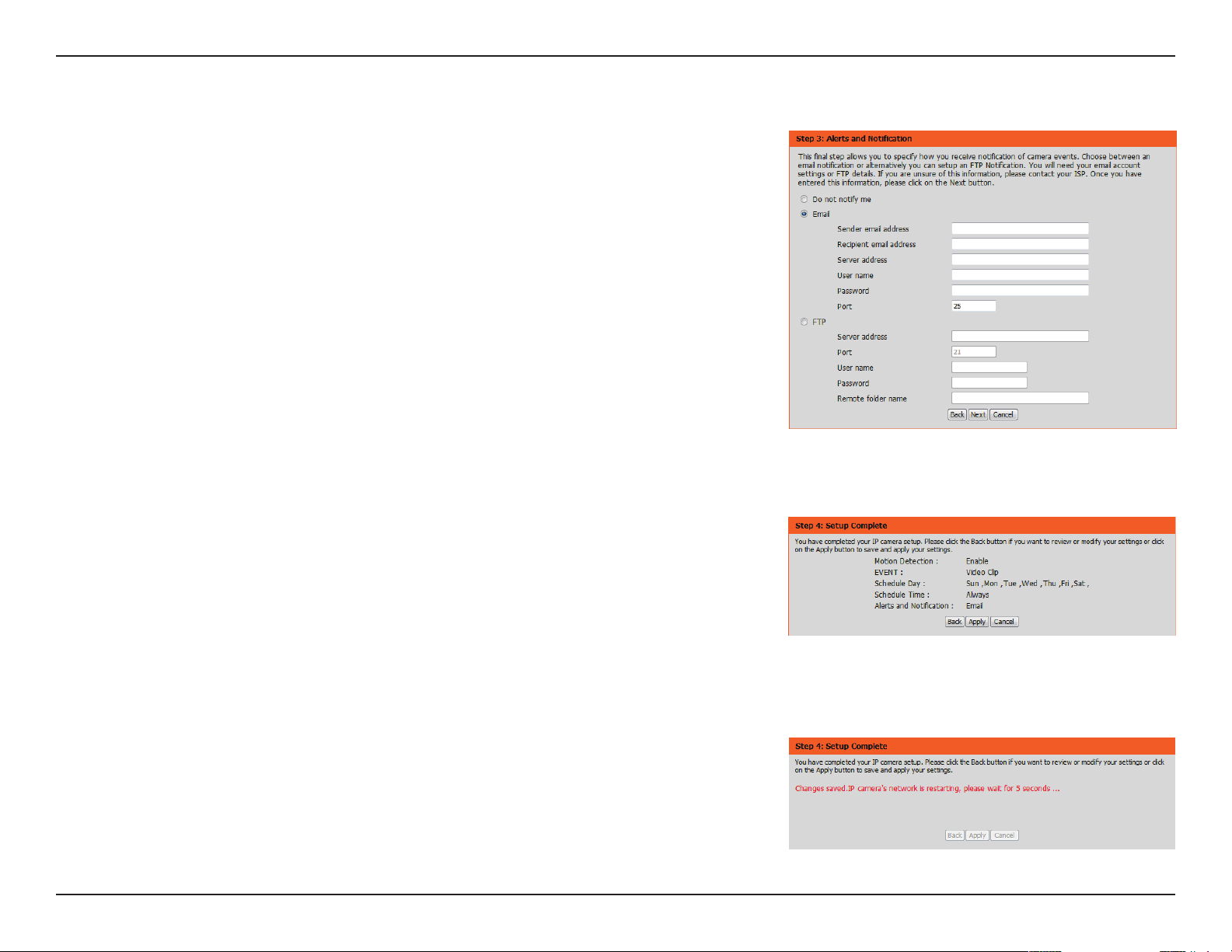
Step 3
This step allows you to specify how you will receive event notications from your camera. You
may choose not to receive notications, or to receive notications via e-mail or FTP.
Please enter the relevant information for your e-mail or FTP account.
Click Next to continue.
Step 4
You have completed the Motion Detection Wizard.
Please verify your settings and click Apply to save them.
Please wait a few moments while the camera saves your settings and restarts.
44D-Link DCS-2132L User Manual
Section 4: Conguration
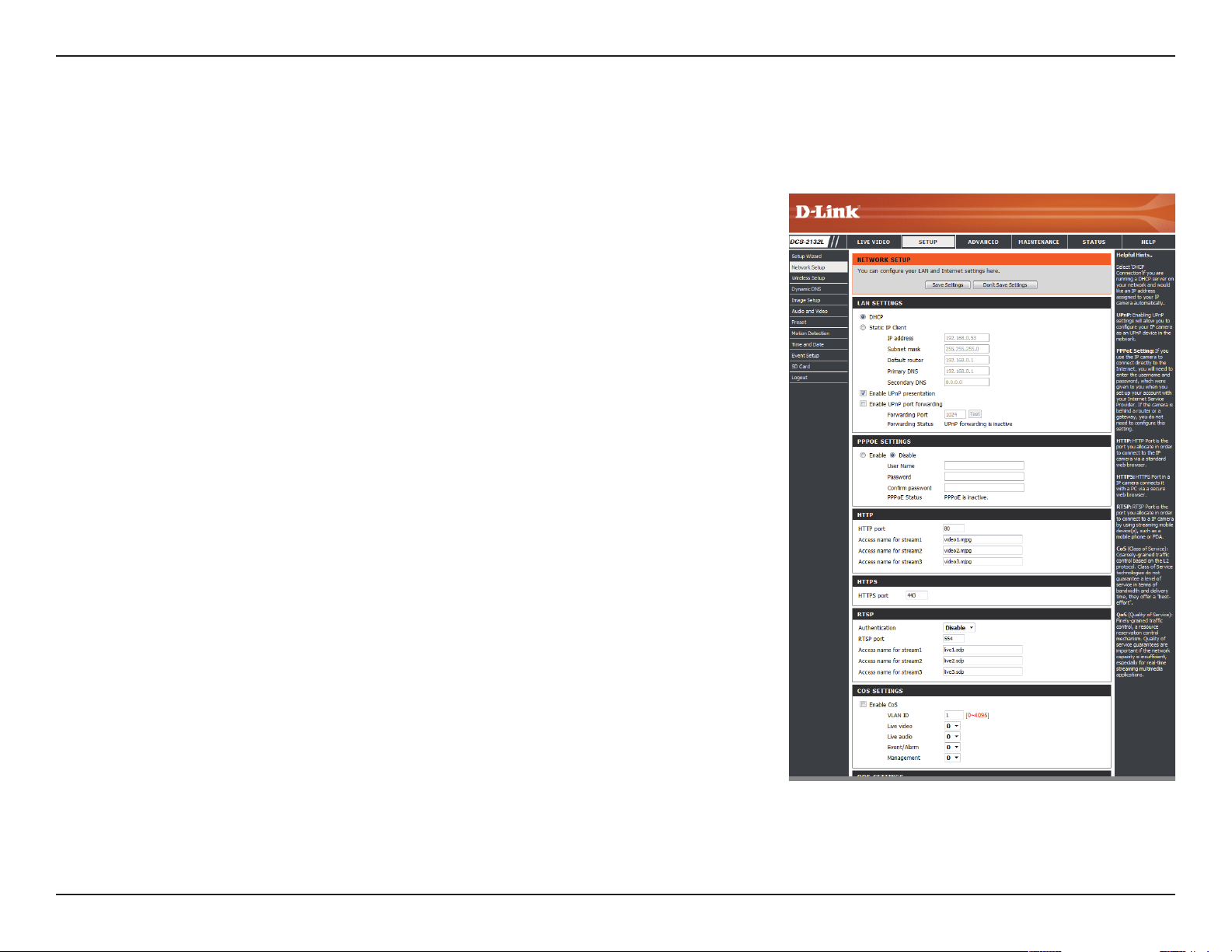
Network Setup
Use this section to congure the network connections for your camera. All relevant information must be entered accurately. After making any
changes, click the Save Settings button to save your changes.
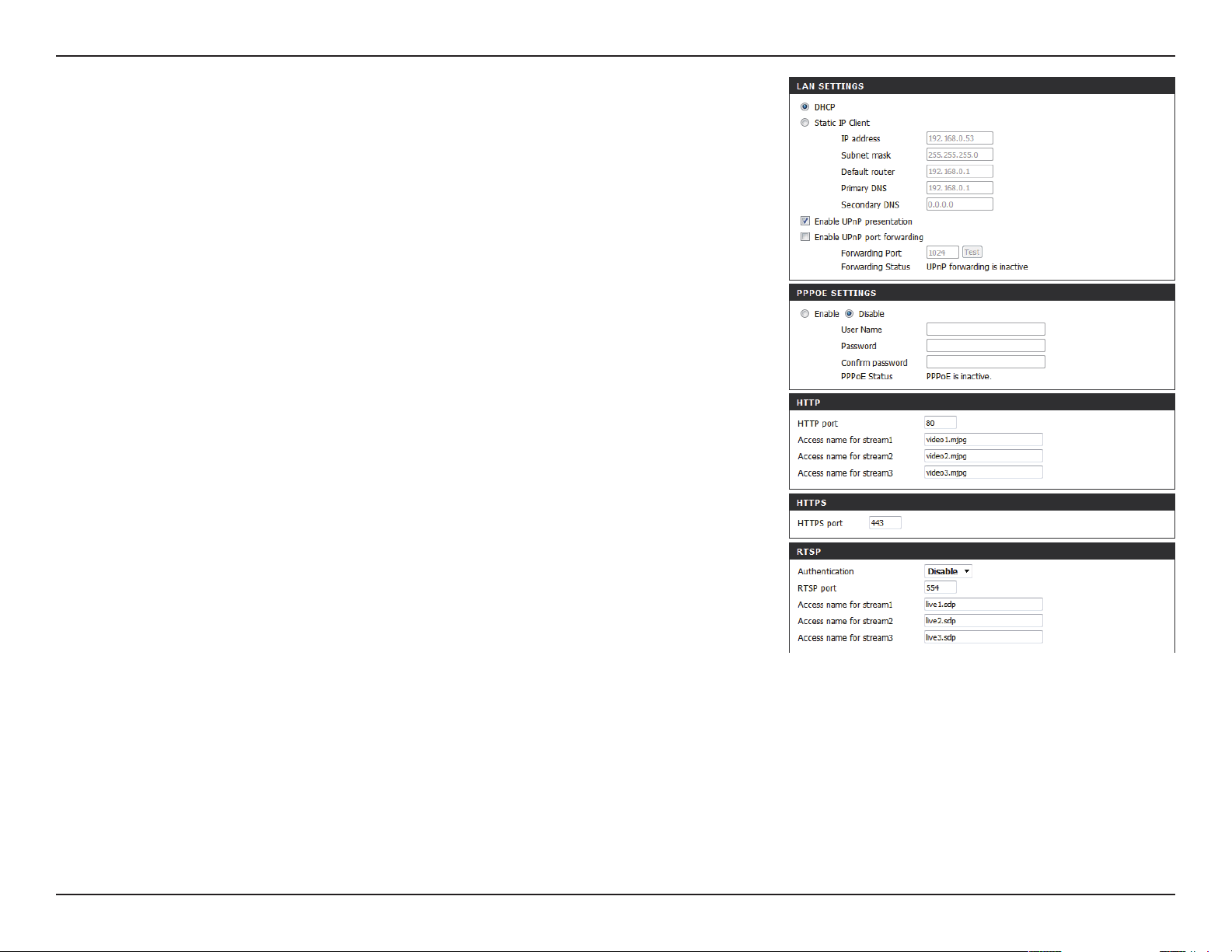
LAN Settings:
DHCP:
Static IP Address:
IP Address:
Subnet Mask:
Default Gateway:
Primary DNS:
Secondary DNS:
This section lets you congure settings for your local
area network.
Select this connection if you have a DHCP server running
on your network and would like your camera to obtain
an IP address automatically.
If you choose DHCP, you do not need to ll out the IP
address settings.
You may obtain a static or xed IP address and other
network information from your network administrator
for your camera. A static IP address may simplify access
to your camera in the future.
Enter the xed IP address in this eld.
This number is used to determine if the destination is in
the same subnet. The default value is 255.255.255.0.
The gateway used to forward frames to destinations in a
dierent subnet. Invalid gateway settings may cause the
failure of transmissions to a dierent subnet.
The primary domain name server translates names to IP
addresses.
The secondary DNS acts as a backup to the primary DNS.
45D-Link DCS-2132L User Manual
Section 4: Conguration
Enable UPnP Presentation:
Enable UPnP Port Forwarding:
Enable PPPoE:
User Name / Password:
HTTP Port:
Access Name for Stream 1~3:
HTTPS Port:
RTSP Port:
Enabling this setting allows your camera to be
congured as a UPnP device on your network.
Enabling this setting allows the camera to add port
forwarding entries into the router automatically on a
UPnP capable network.
Enable this setting if your network uses PPPoE.
Enter the username and password for your PPPoE
account. Re-enter your password in the Conrm
Password eld. You may obtain this information from
your ISP.
The default port number is 80.
The default name is video#.mjpg, where # is the number
of the stream.
You may use a PC with a secure browser to connect to
the HTTPS port of the camera. The default port number
is 443.
The port number that you use for RTSP streaming to
mobile devices, such as mobile phones or PDAs. The
default port number is 554. You may specify the address
of a particular stream. For instance, live1.sdp can be
accessed at rtsp://x.x.x.x/video1.sdp where the x.x.x.x
represents the ip address of your camera.
46D-Link DCS-2132L User Manual
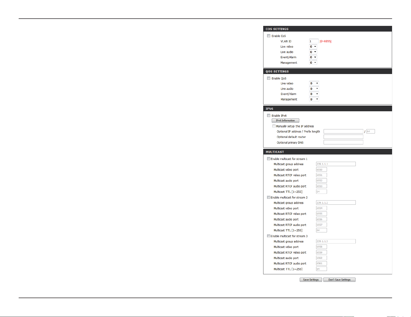
Section 4: Conguration
Enable CoS:
Enable QoS:
Enable IPV6:
Enable Multicast for stream
Enabling the Class of Service setting implements a
best-eort policy without making any bandwidth
reservations.
Enabling QoS allows you to specify a trac priority
policy to ensure a consistent Quality of Service during
busy periods. If the Network Camera is connected to a
router that itself implements QoS, the router's settings
will override the QoS settings of the camera.
Enable the IPV6 setting to use the IPV6 protocol.
Enabling the option allows you to manually set up
the address, specify an optional IP address, specify an
optional router and an optional primary DNS.
The DCS-2132L allows you to multicast each of the
available streams via group address and specify the TTL
value for each stream. Enter the port and TTL settings
you wish to use if you do not want to use the defaults.
47D-Link DCS-2132L User Manual
Section 4: Conguration
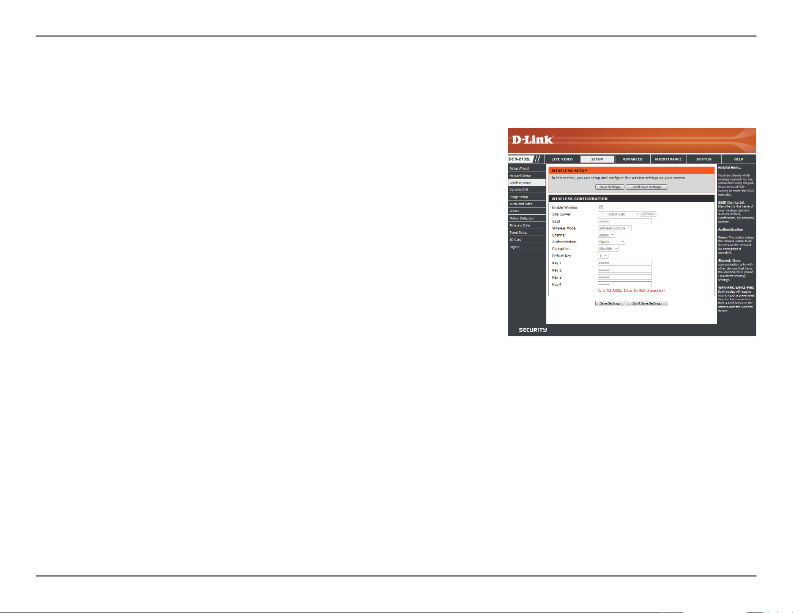
Wireless Setup
This section allows you to set up and congure the wireless settings on your camera. After making any changes, click the Save Settings button to
save your changes.
Site Survey:
SSID:
Wireless Mode:
Channel:
Authentication:
Encryption:
Key:
Click the Rescan button to scan for available wireless
networks. After scanning, you can use the drop-down
box to select an available wireless network. The related
information (SSID, Wireless Mode, Channel, Authentication,
Encryption) will be automatically lled in for you.
Enter the SSID of the wireless access point you wish to
use.
Use the drop-down box to select the mode of the
wireless network you wish to connect to. Infrastructure
is normally used to connect to an access point or router.
Ad-Hoc is usually used to connect directly to another
computer.
If you are using Ad Hoc mode, select the channel of the
wireless network you wish to connect to, or select Auto.
Select the authentication you use on your wireless
network - Open, Shared, WPA-PSK, or WPA2-PSK.
If you use WPA-PSK or WPA2-PSK authentication, you
will need to specify whether your wireless network
uses TKIP or AES encryption. If you use Open or Shared
authentication, WEP encryption should be the setting.
If you use WEP, WPA-PSK, or WPA2-PSK authentication,
enter the Key (also known as password) used for your
wireless network.
48D-Link DCS-2132L User Manual
Section 4: Conguration
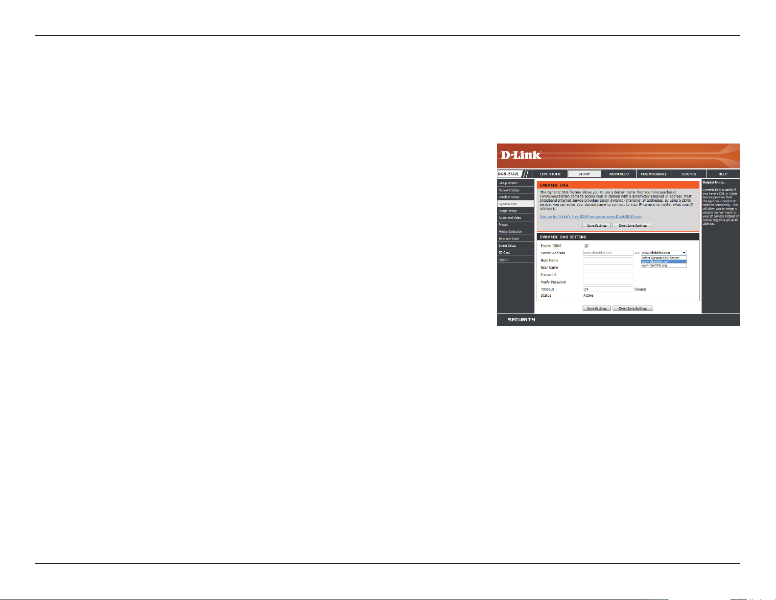
Dynamic DNS
DDNS (Dynamic Domain Name Server) will hold a DNS host name and synchronize the public IP address of the modem when it has been modied.
A user name and password are required when using the DDNS service. After making any changes, click the Save Settings button to save your
changes.
Enable DDNS:
Server Address:
Host Name:
User Name:
Password:
Timeout:
Status:
Select this checkbox to enable the DDNS function.
Select your Dynamic DNS provider from the pull down
menu or enter the server address manually.
Enter the host name of the DDNS server.
Enter the user name or e-mail used to connect to your
DDNS account.
Enter the password used to connect to your DDNS
server account.
Enter the DNS timeout values you wish to use.
Indicates the connection status, which is automatically
determined by the system.
49D-Link DCS-2132L User Manual
Section 4: Conguration
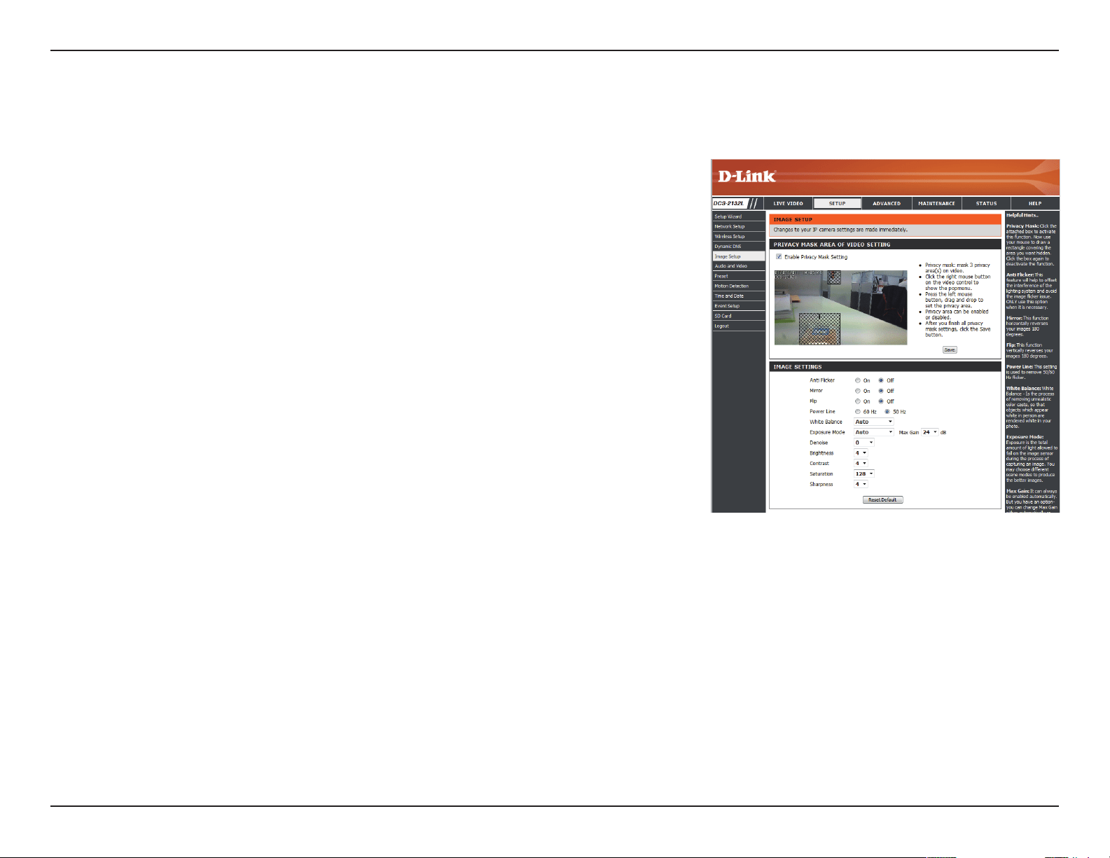
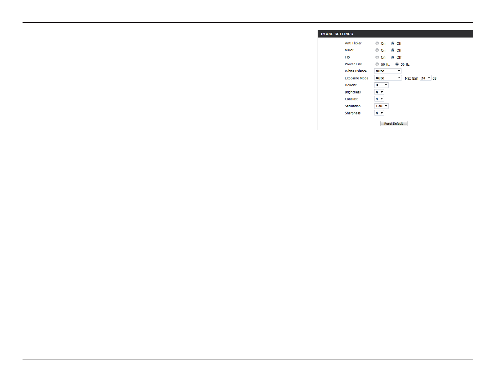
Image Setup
In this section, you may congure the video image settings for your camera. A preview of the image will be shown in Live Video.
Enable Privacy Mask:
Anti Flicker:
Mirror:
Flip:
Power Line:
White Balance:
The Privacy Mask setting allows you to specify up to 3
rectangular areas on the camera's image to be blocked/
excluded from recordings and snapshots.
You may click and drag the mouse cursor over the
camera image to draw a mask area. Right clicking on the
camera image brings up the following menu options:
Disable All: Disables all mask areas
Enable All: Enables all mask areas
Reset All: Clears all mask areas.
If the video ickers, try enabling this setting.
This will mirror the image horizontally.
This will ip the image vertically. When turning Flip on,
you may want to consider turning Mirror on as well.
Select the frequency used by your power lines to avoid
interference or distortion.
Use the drop-down box to change white balance settings
to help balance colors for dierent environments. You
can choose from Auto, Outdoor, Indoor, Fluorescent,
and Push Hold.
50D-Link DCS-2132L User Manual
Section 4: Conguration
Exposure Mode:
Denoise:
Brightness:
Contrast:
Saturation:
Sharpness:
Reset Default:
Changes the exposure mode. Use the drop-down
box to set the camera for Indoor, Outdoor, or Night
environments, or to Moving to capture moving objects.
The Low Noise option will focus on creating a high-
quality picture without noise. You can also create 3
dierent custom exposure modes. The Max Gain setting
will allow you to control the maximum amount of gain
to apply to brighten the picture.
This setting controls the amount of noise reduction that
will be applied to the picture.
Adjust this setting to compensate for backlit subjects.
Adjust this setting to alter the color intensity/strength.
This setting controls the amount of coloration, from
grayscale to fully saturated.
Specify a value from 0 to 8 to specify how much
sharpening to apply to the image.
Click this button to reset the image to factory default
settings.
51D-Link DCS-2132L User Manual
Section 4: Conguration
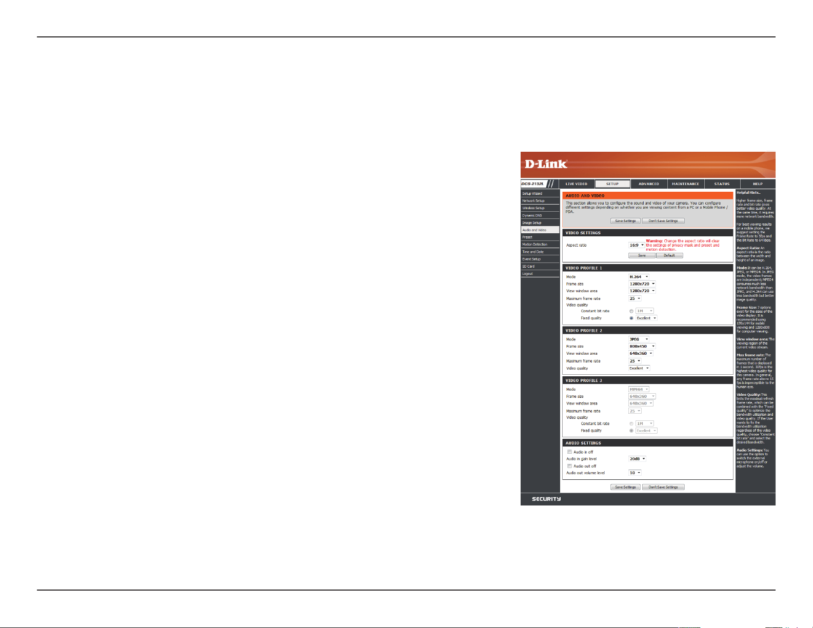
Audio and Video
You may congure up to 3 video proles with dierent settings for your camera. Hence, you may set up dierent proles for your computer and
mobile display. In addition, you may also congure the two-way audio settings for your camera. After making any changes, click the Save Settings
button to save your changes.
Number of active proles:
Aspect ratio:
Mode:
Frame size / View window area:
You can use the drop-down box to set up to 2 active
proles.
Set the aspect ratio of the video to 4:3 standard or 16:9
widescreen.
Set the video codec to be used to JPEG, MPEG-4, or
H.264.
Frame size determines the total capture resolution, and
View window area determines the Live Video viewing
window size. If the Frame size is larger than the Live
Video size, you can use the ePTZ controls to look around.
16:9 1280 x 800, 1280 x 720, 800 x 450,
640 x 360, 480 x 270, 320 x 176,
176 x 144
4:3 1024 x 768, 800 x 600, 640 x 480,
480 x 360, 320 x 240, 176 x 144
Note: If your View window area is the same as your Frame
size, you will not be able to use the ePTZ function.
52D-Link DCS-2132L User Manual
Section 4: Conguration
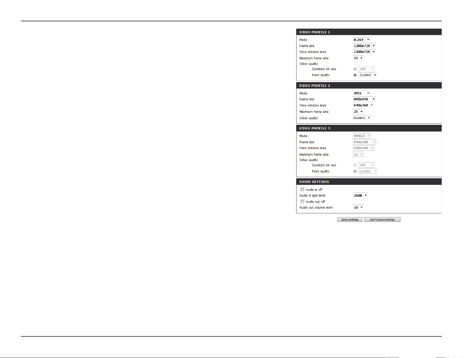
Maximum frame rate:
Video Quality:
Constant bit rate:
Fixed quality:
Audio in o:
Audio in gain level:
Audio out o:
Audio out volume level:
A higher frame rate provides smoother motion for
videos, and requires more bandwidth. Lower frame
rates will result in stuttering motion, and requires less
bandwidth.
This limits the maximum frame rate, which can be
combined with the "Fixed quality" option to optimize
the bandwidth utilization and video quality. If xed
bandwidth utilization is desired regardless of the video
quality, choose "Constant bit rate" and select the desired
bandwidth.
The bps will aect the bit rate of the video recorded
by the camera. Higher bit rates result in higher video
quality.
Select the image quality level for the camera to try to
maintain. High quality levels will result in increased bit
rates.
Selecting this checkbox will mute incoming audio.
This setting controls the amount of gain applied to
incoming audio to increase its volume.
Selecting this checkbox will mute outgoing audio.
This setting controls the amount of gain applied to
outgoing audio to increase its volume.
53D-Link DCS-2132L User Manual
Section 4: Conguration
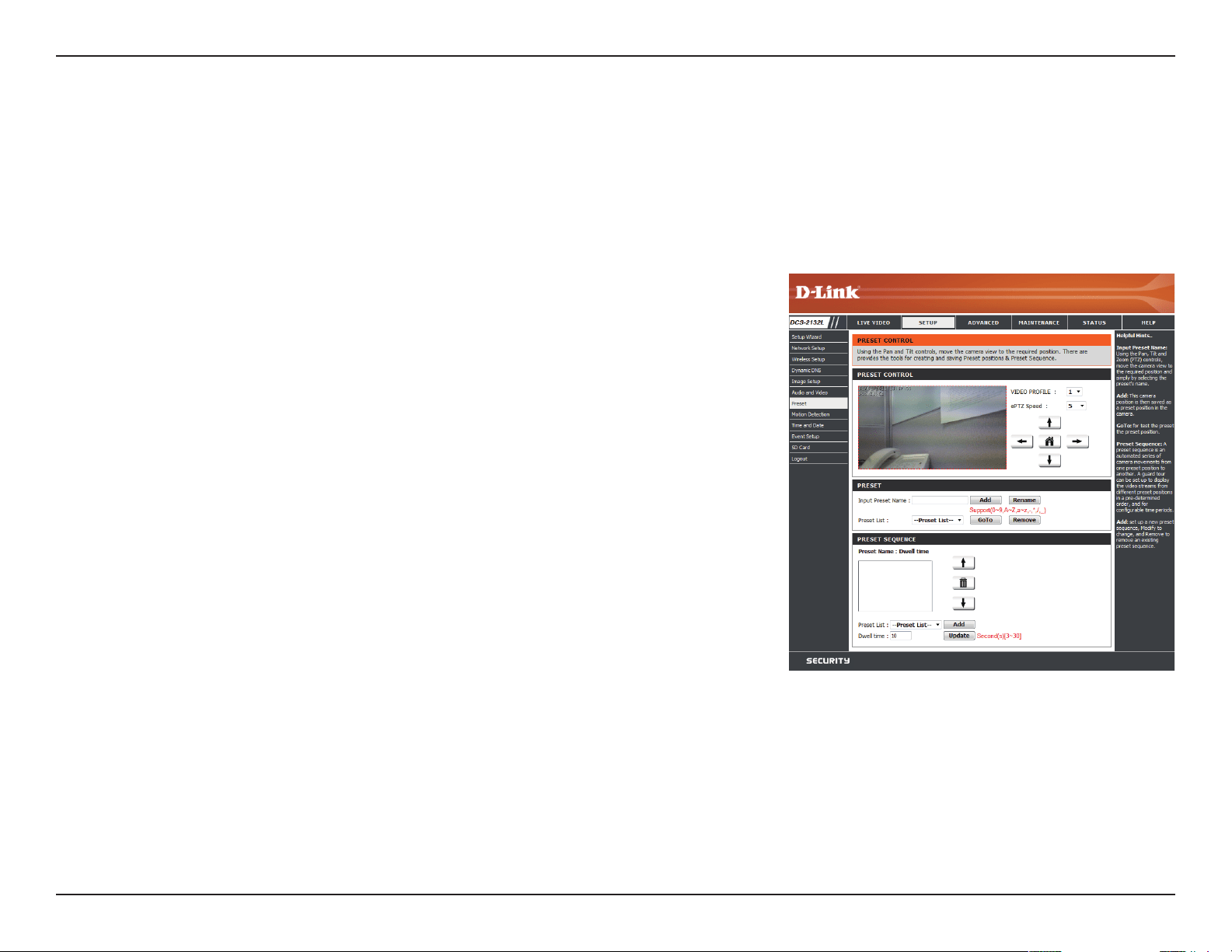
Preset
This screen allows you to set preset points for the ePTZ function of the camera, which allows you to look around the camera's viewable area by
using a zoomed view. Presets allow you to quickly go to and view a specic part of the area your camera is covering, and you can create preset
sequences, which will automatically change the camera's view between the dierent presets according to a dened order and timing you can set.
Note: If your View window area is the same as your Frame size, you will not be able to use the ePTZ function.
Video Prole:
ePTZ Speed:
Arrow Buttons and Home Button:
Input Preset Name:
Preset List:
Preset Sequence:
This selects which video prole to use.
You may select a value between 0 and 64. 0 is the slowest
and 64 is the fastest.
Use these buttons to move to a specic part of the
viewing area, which you can then set as a preset. Click
the Home button to return to the center of the viewing
area.
Enter the name of the preset you want to create, then
click the Add button to make a new preset. If an existing
preset has been selected from the Preset List, you can
change its name by typing in a new name, then clicking
the Rename button.
Click this drop-down box to see a list of all the presets
that have been created. You can select one, then click
the GoTo button to change the displayed camera view
to the preset. Clicking the Remove button will delete
the currently selected preset.
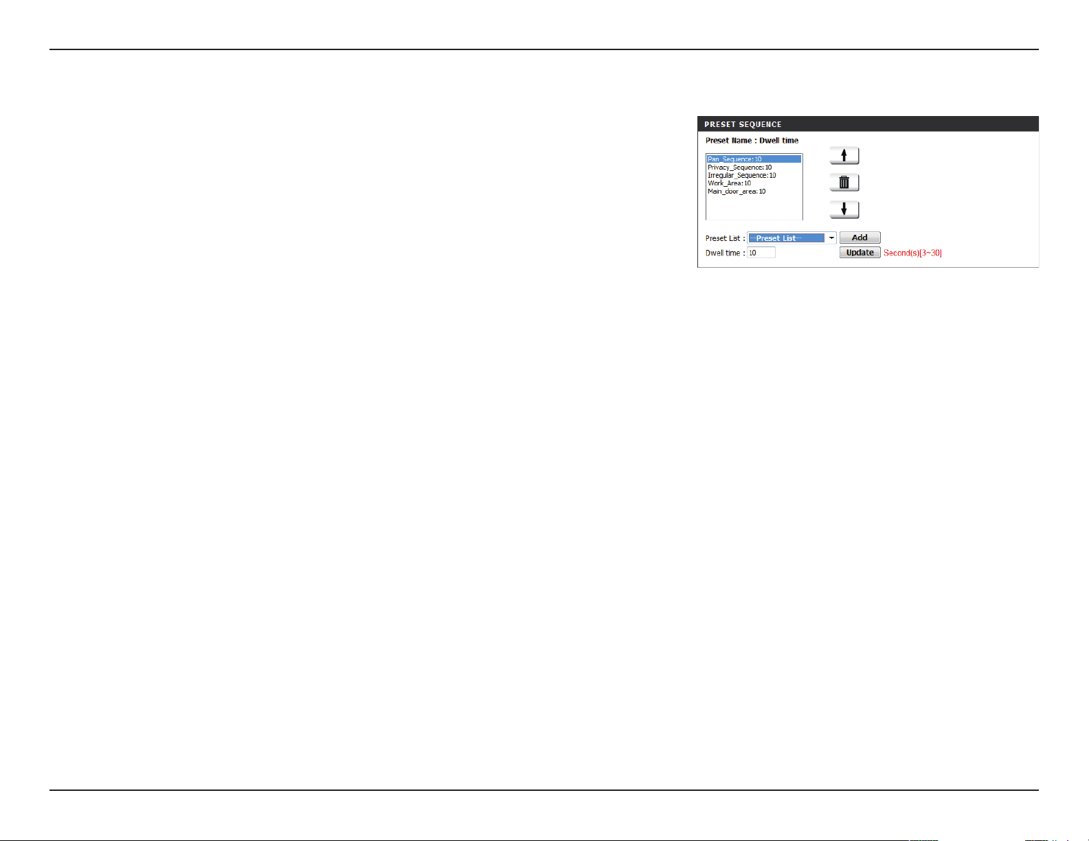
This section allows you to create a preset sequence,
which automatically moves the camera's view between
a set of preset views.
54D-Link DCS-2132L User Manual
Section 4: Conguration
Preset List: To add a preset to the sequence, select it from the drop-
down box at the bottom of this window, set the Dwell
time to determine how long the camera view will stay at
that preset, then click the Add button. The preset name
will appear in the list, followed by the dwell time to view
that preset for.
You can rearrange your presets in the sequence by
selecting a preset in the sequence, then clicking the
arrow buttons to move it higher or lower in the current
sequence.
Clicking the trash can button will remove the currently
selected preset from the sequence.
If you want to change the dwell time for a preset, select
it from the list, enter a new dwell time, then click the
Update button.
55D-Link DCS-2132L User Manual
Section 4: Conguration
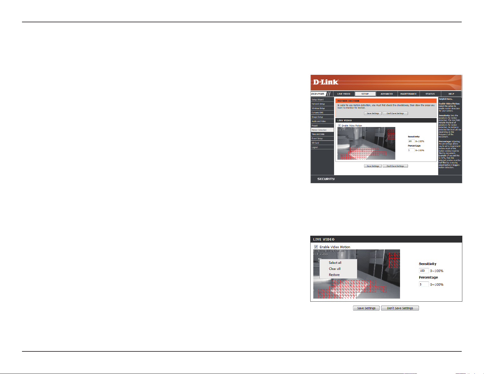
Motion Detection
Enabling Video Motion will allow your camera to use the motion detection feature. You may draw a nite motion area that will be used for
monitoring. After making any changes, click the Save Settings button to save your changes.
Enable Video Motion:
Sensitivity:
Percentage:
Draw Motion Area:
Erase Motion Area:
Select this box to enable the motion detection feature
of your camera.
Species the measurable dierence between two
sequential images that would indicate motion. Please
enter a value between 0 and 100.
Species the amount of motion in the window being
monitored that is required to initiate an alert. If this is set
to 100%, motion is detected within the whole window
will trigger a snapshot.
Draw the motion detection area by dragging your mouse
in the window (indicated by the red square).
To erase a motion detection area, simply click on the red
square that you wish to remove.
Right clicking on the camera image brings up the
following menu options:
Select All: Draws a motion detection area over the
entire screen.
Clear All: Clears any motion detection areas that have
been drawn.
Restore: Restores the previously specied motion
detection areas.

56D-Link DCS-2132L User Manual
Section 4: Conguration
Time and Date
This section allows you to automatically or manually congure, update, and maintain the internal system clock for your camera. After making any
changes, click the Save Settings button to save your changes.
Time Zone:
Enable Daylight Saving:
Auto Daylight Saving:
Set Date and Time Manually:
Oset:
Synchronize with NTP Server:
NTP Server:
Set the Date and Time Manually:
Copy Your Computer's Time
Settings:
Select your time zone from the drop-down menu.
Select this to enable Daylight Saving Time.
Select this option to allow your camera to congure the
Daylight Saving settings automatically.
Selecting this option allows you to congure the Daylight
Saving date and time manually.
Sets the amount of time to be added or removed when
Daylight Saving is enabled.
Enable this feature to obtain time automatically from an
NTP server.
Network Time Protocol (NTP) synchronizes the DCS-
2132L with an Internet time server. Choose the one that
is closest to your location.
This option allows you to set the time and date manually.
This will synchronize the time information from your PC.
57D-Link DCS-2132L User Manual
Section 4: Conguration
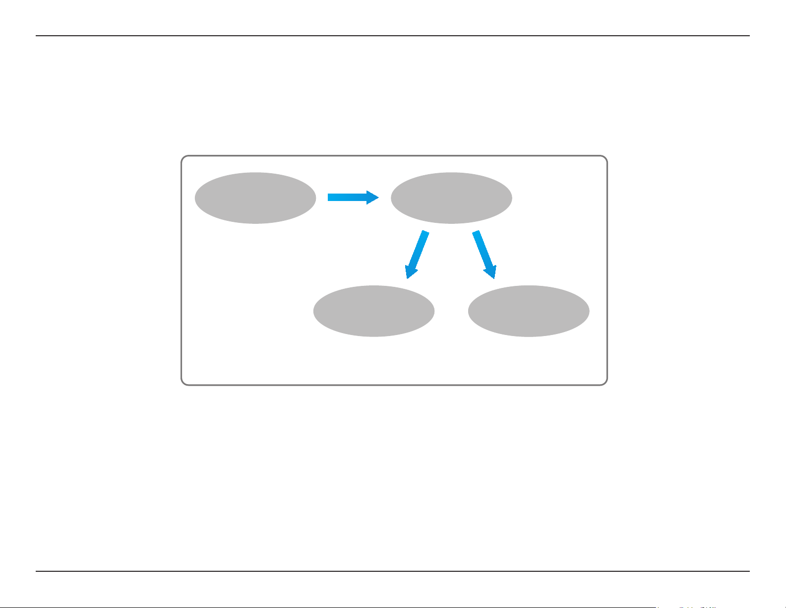
Event Setup
In a typical application, when motion is detected, the DCS-2132L sends images to a FTP server or via e-mail as notications. As shown in the
illustration below, an event can be triggered by many sources, such as motion detection or external digital input devices. When an event is
triggered, a specied action will be performed. You can congure the Network Camera to send snapshots or videos to your e-mail address or FTP
site.
ex.
Motion detection,
Periodically, Digital input,
System reboot
Event Condition
ex.
Snapshot, Video Clips
ex.
Email, FTP
Media
(what to send)
Server
(where to send)
Action
To start plotting an event, it is suggested to congure server and media columns rst so that the Network Camera will know what action shall be
performed when a trigger is activated.
58D-Link DCS-2132L User Manual
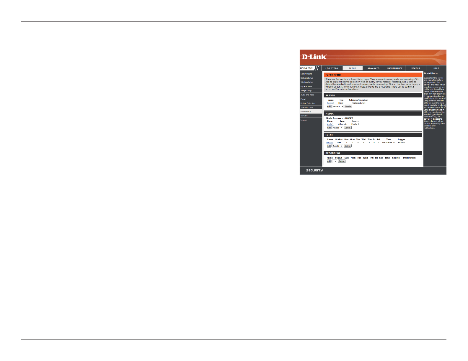
Section 4: Conguration
The Event Setup page includes 4 dierent sections.
• Event
• Server
• Media
• Recording
1. To add a new item - "event, server or media," click Add. A screen will appear and allow you
to update the elds accordingly.
2. To delete the selected item from the pull-down menu of event, server or media, click Delete.
3. Click on the item name to pop up a window for modifying.
59D-Link DCS-2132L User Manual
Section 4: Conguration
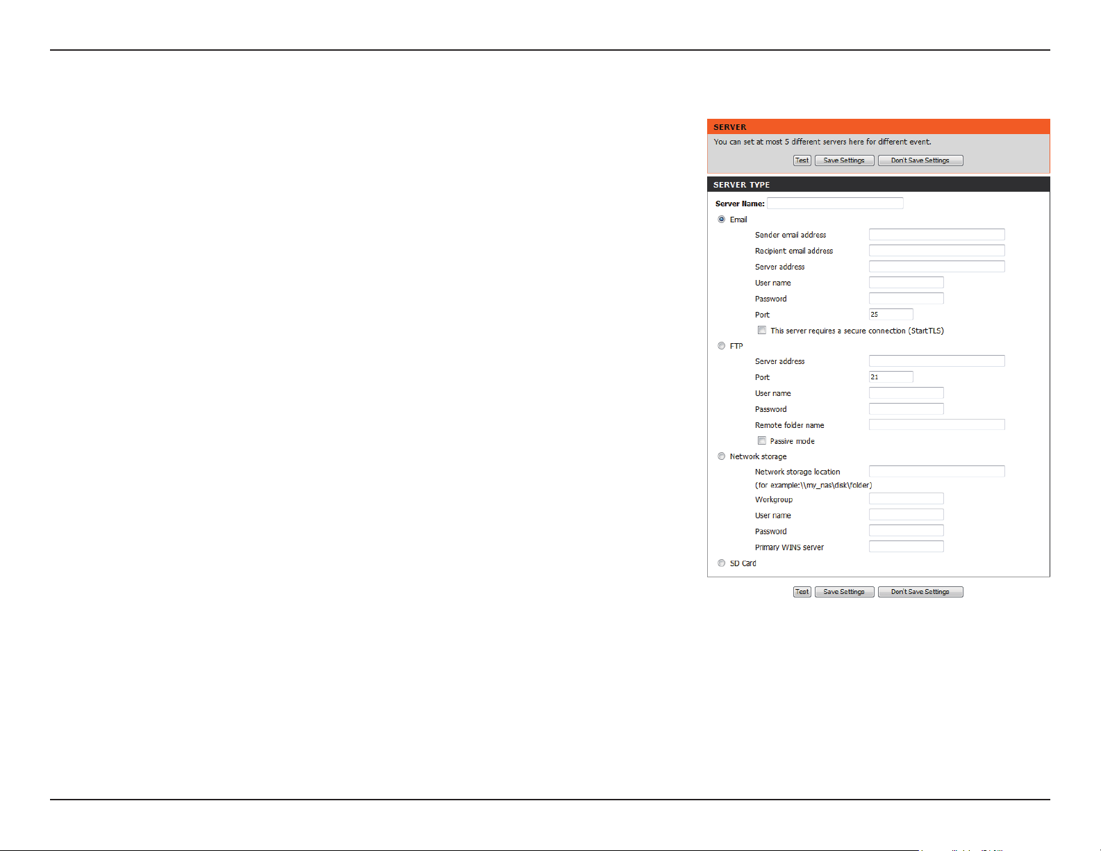
Add Server
Server Name:
E-mail:
FTP:
Network Storage:
SD Card:
Enter the unique name of your server.
Enter the conguration for the target e-mail server
account.
Enter the conguration for the target FTP server account.
Specify a network storage device. Only one network
storage device is supported.
Use the camera's onboard SD card storage.
You can congure up to 5 servers to save snapshots and/or video to. After making any
changes, click the Save Settings button to save your changes.
60D-Link DCS-2132L User Manual
Section 4: Conguration
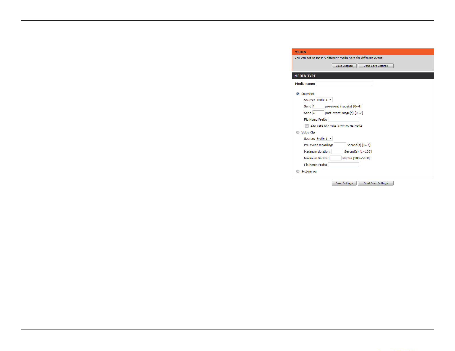
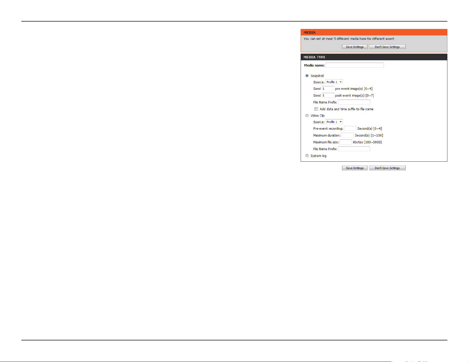
Add Media
Media Name:
Snapshot:
Source:
Send pre-event image(s) [0~4]:
Send post-event image(s) [0~7]:
File name prex:
Add date and time sux to le
name:
Enter a unique name for media type you want to create.
Select this option to set the media type to snapshots.
Set the video prole to use as the media source. Refer
to Audio and Video on "Audio and Video" on page 51 for
more information on video proles.
Set the number of pre-event images to take. Pre-event
images are images taken before the main event snapshot
is taken.
Set the number of post-event images to take. Post-event
images are images taken after the main event snapshot
is taken. You can set up to 7 post-event images to be
taken.
The prex name will be added on the le name.
Check it to add timing information as le name sux.
There are three types of media, Snapshot, Video Clip, and System Log. After making any
changes, click the Save Settings button to save your changes.
61D-Link DCS-2132L User Manual
Section 4: Conguration
Video clip:
Source:
Pre-event recording:
Maximum duration:
Maximum le size:
File name prex:
System log:
Select this option to set the media type to video clips.
Set the video prole to use as the media source. Refer to
"Audio and Video" on page 51 for more information on
video proles.
This sets how many seconds to record before the main
event video clip starts. You can record up to 4 seconds of
pre-event video.
Set the maximum length of video to record for your
video clips.
Set the maximum le size to record for your video clips.
This is the prex that will be added to the lename of
saved video clips.
Select this option to set the media type to system logs.
This will save the event to the camera system log, but
will not record any snapshots or video.
62D-Link DCS-2132L User Manual
Section 4: Conguration
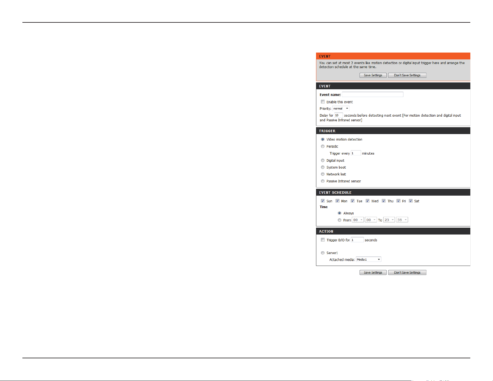
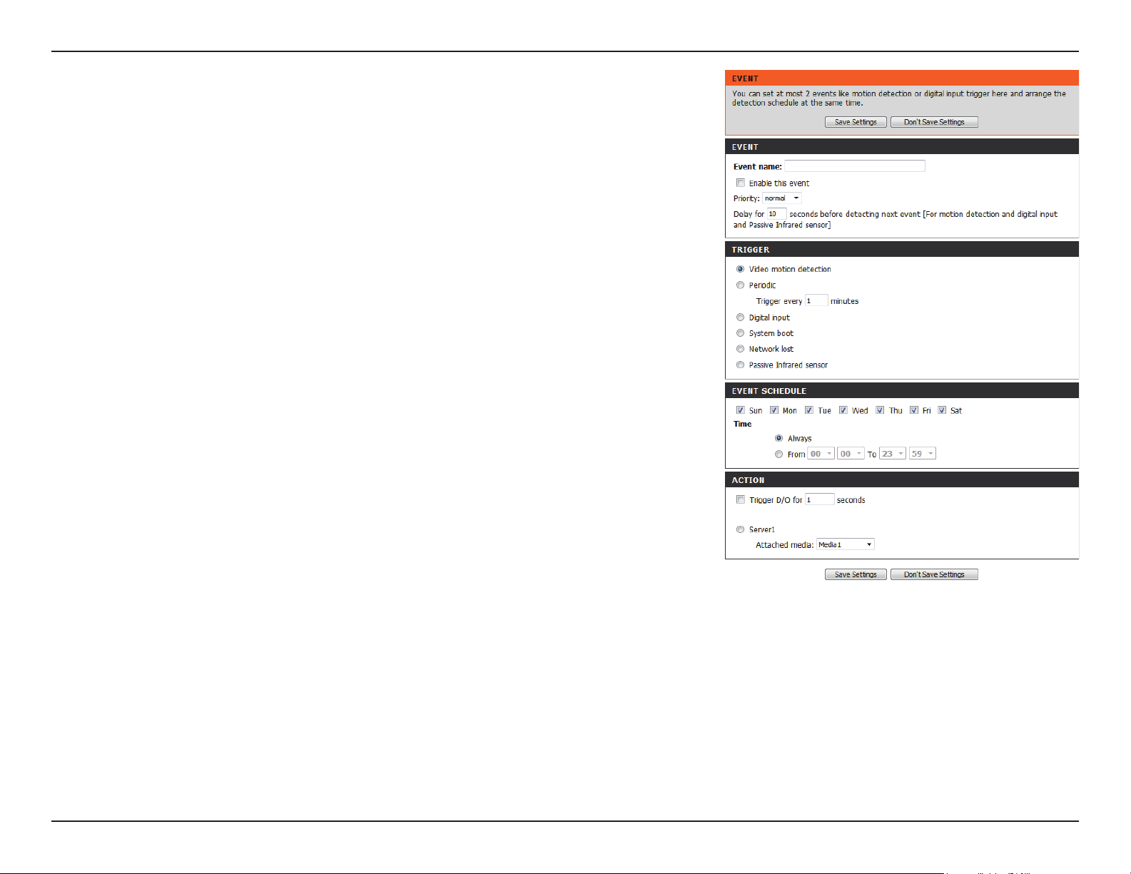
Add Event
Create and schedule up to 2 events with their own settings here. After making any changes,
click the Save Settings button to save your changes.
Event name:
Enable this event:
Priority:
Delay:
Trigger:
Video Motion Detection:
Periodic:
Digital input:
System Boot:
Network Lost:
Passive Infrared Sensor:
Enter a name for the event.
Select this box to activate this event.
Set the priority for this event. The event with higher
priority will be executed rst.
Select the delay time before checking the next event. It
is being used for both events of motion detection and
digital input trigger.
Specify the input type that triggers the event.
Motion is detected during live video monitoring. Select
the windows that need to be monitored.
The event is triggered in specied intervals. The trigger
interval unit is in minutes.
The external trigger input to the camera.
Triggers an event when the system boots up.
Triggers an event when the network connection is lost.
Triggers an event when the PIR sensor is activated by
moving infrared objects even in dark environment.
63D-Link DCS-2132L User Manual
Section 4: Conguration
Time:
Trigger D/O:
Server:
Select Always or enter the time interval.
Select to trigger the digital output for a specic number
of seconds when an event occurs.
Specify the location where the event information should
be saved to.
64D-Link DCS-2132L User Manual
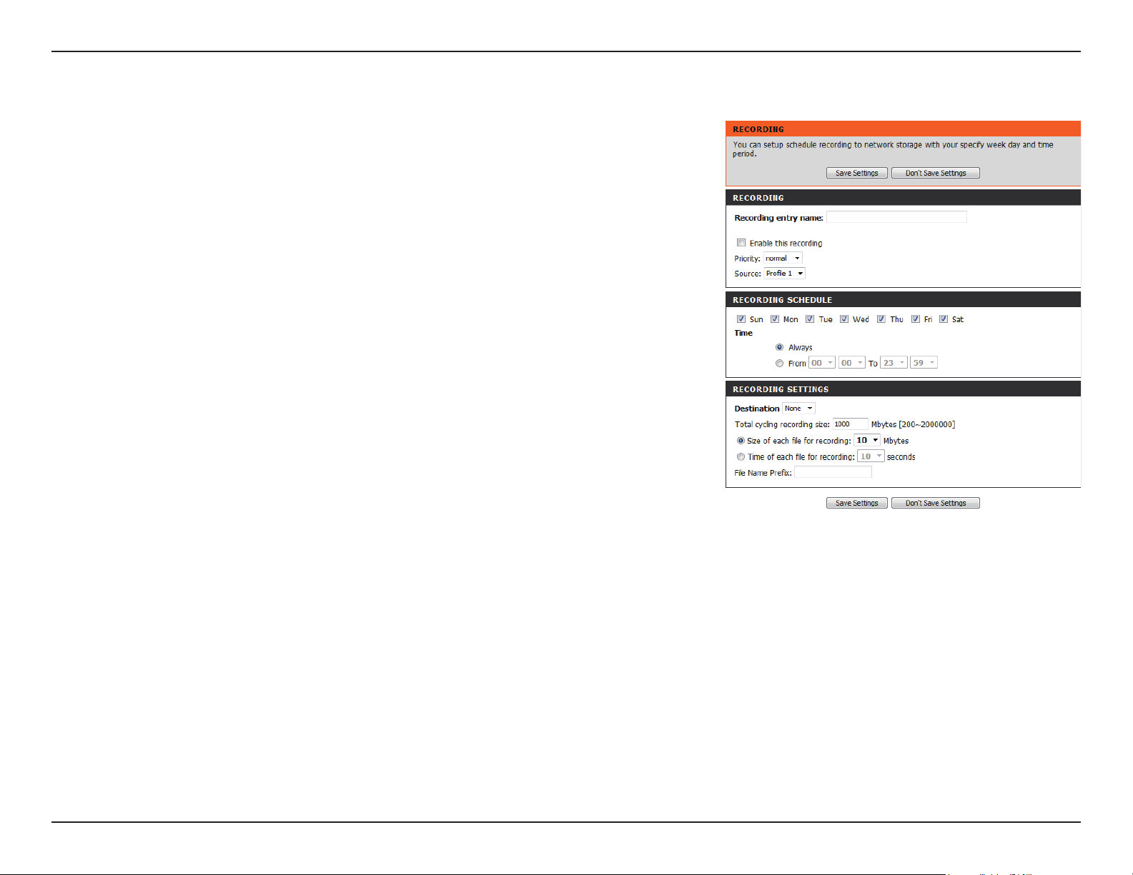
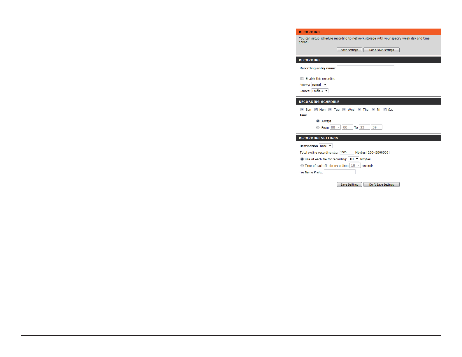
Section 4: Conguration
Add Recording
Recording entry name:
Enable this recording:
Priority:
Source:
Recording schedule:
Recording settings:
Destination:
Total cycling recording size:
The unique name of the entry.
Select this to enable the recording function.
Set the priority for this entry. The entry with a higher
priority value will be executed rst.
The source of the stream.
Scheduling the recording entry.
Conguring the setting for the recording.
Select the folder where the recording le will be stored.
Please input a HDD volume between 1MB and 2TB for
recording space. The recording data will replace the
oldest record when the total recording size exceeds this
value. For example, if each recording le is 6MB, and the
total cyclical recording size is 600MB, then the camera
will record 100 les in the specied location (folder) and
then will delete the oldest le and create new le for
cyclical recording.
Please note that if the free HDD space is not enough, the
recording will stop. Before you set up this option please
make sure your HDD has enough space, and it is better to
not save other les in the same folder as recording les.
Here you can congure and schedule the recording settings. After making any changes,
click the Save Settings button to save your changes.
65D-Link DCS-2132L User Manual
Section 4: Conguration
Size of each le for recording:
Time of each le for recording:
File Name Prex:
If this is selected, les will be separated based on the le
size you specify.
If this is selected, les will be separated based on the
maximum length you specify.
The prex name will be added on the le name of the
recording le(s).
66D-Link DCS-2132L User Manual
Section 4: Conguration
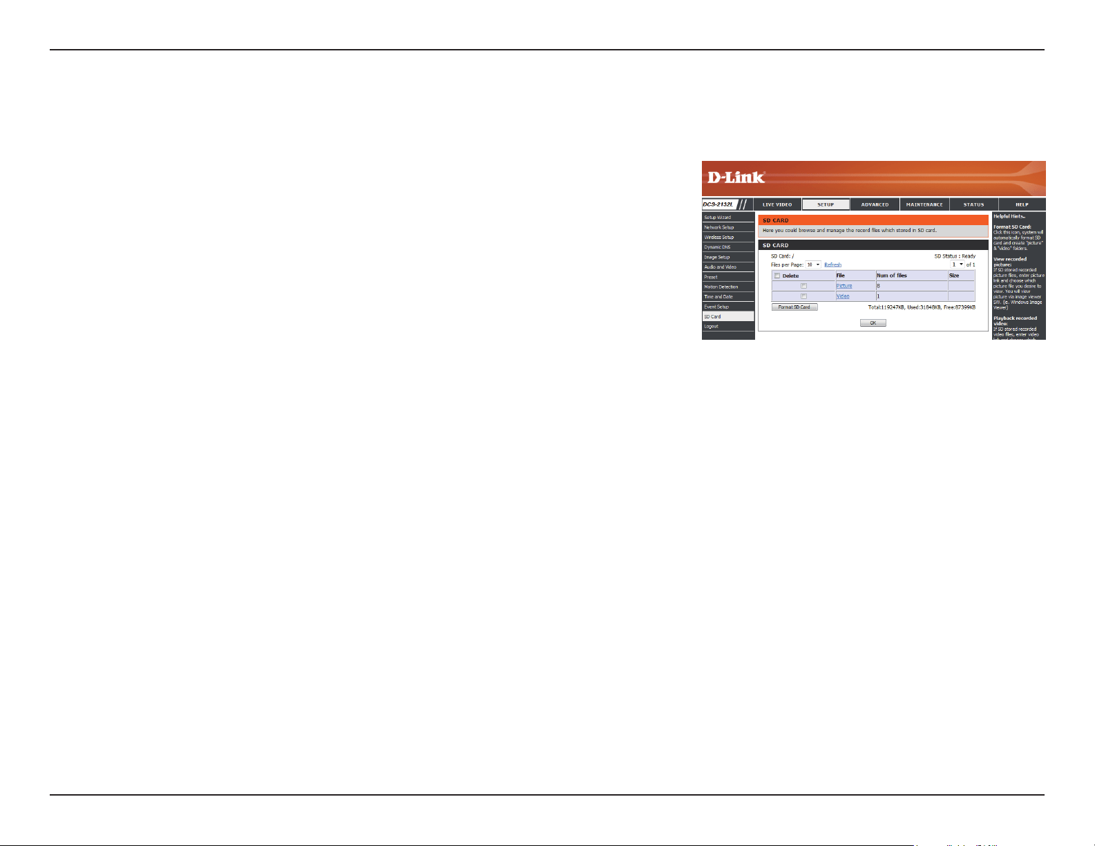
SD Card
Format SD Card:
View Recorded Picture:
Playback Recorded Video:
Refresh:
Click this icon to automatically format the SD card and
create "picture" & "video" folders.
If the picture les are stored on the SD card, click on the
picture folder and choose the picture le you would like
to view.
If video les are stored on the SD card, click on the video
folder and choose the video le you would like to view.
Reloads the le and folder information from the SD card.
Here you may browse and manage the recorded les which are stored on the SD card.
67D-Link DCS-2132L User Manual
Section 4: Conguration
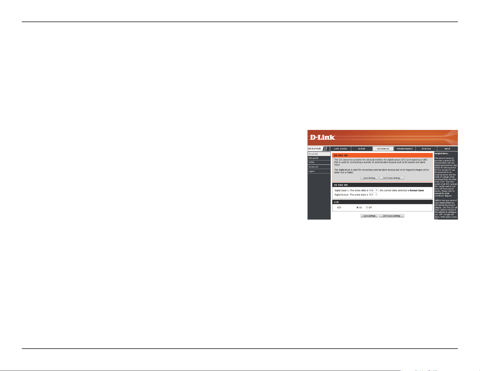
Advanced
This screen allows you to control the behavior of digital input and digital output devices. The I/O connector provides the physical interface for
digital output (DO) and digital input (DI) that is used for connecting a variety of external alarm devices such as IR-Sensors and alarm relays. The
digital input is used for connecting external alarm devices and once triggered images will be taken and e-mailed. After making any changes, click
the Save Settings button to save your changes.
Digital Input/Output
Select D/I or D/O Mode:
LED:
The camera will send a signal when an event is triggered,
depending upon the type of device connected to the DI
circuit.
N.C. stands for Normally Closed. This means that the
normal state of the circuit is closed. Therefore events are
triggered when the device status changes to "Open."
N.O. stands for Normally Open. This means that the
normal state of the circuit is open. Therefore events are
triggered when the device status changes to "Closed."
You may specify whether or not to illuminate the status
LED on the camera.
68D-Link DCS-2132L User Manual
Section 4: Conguration
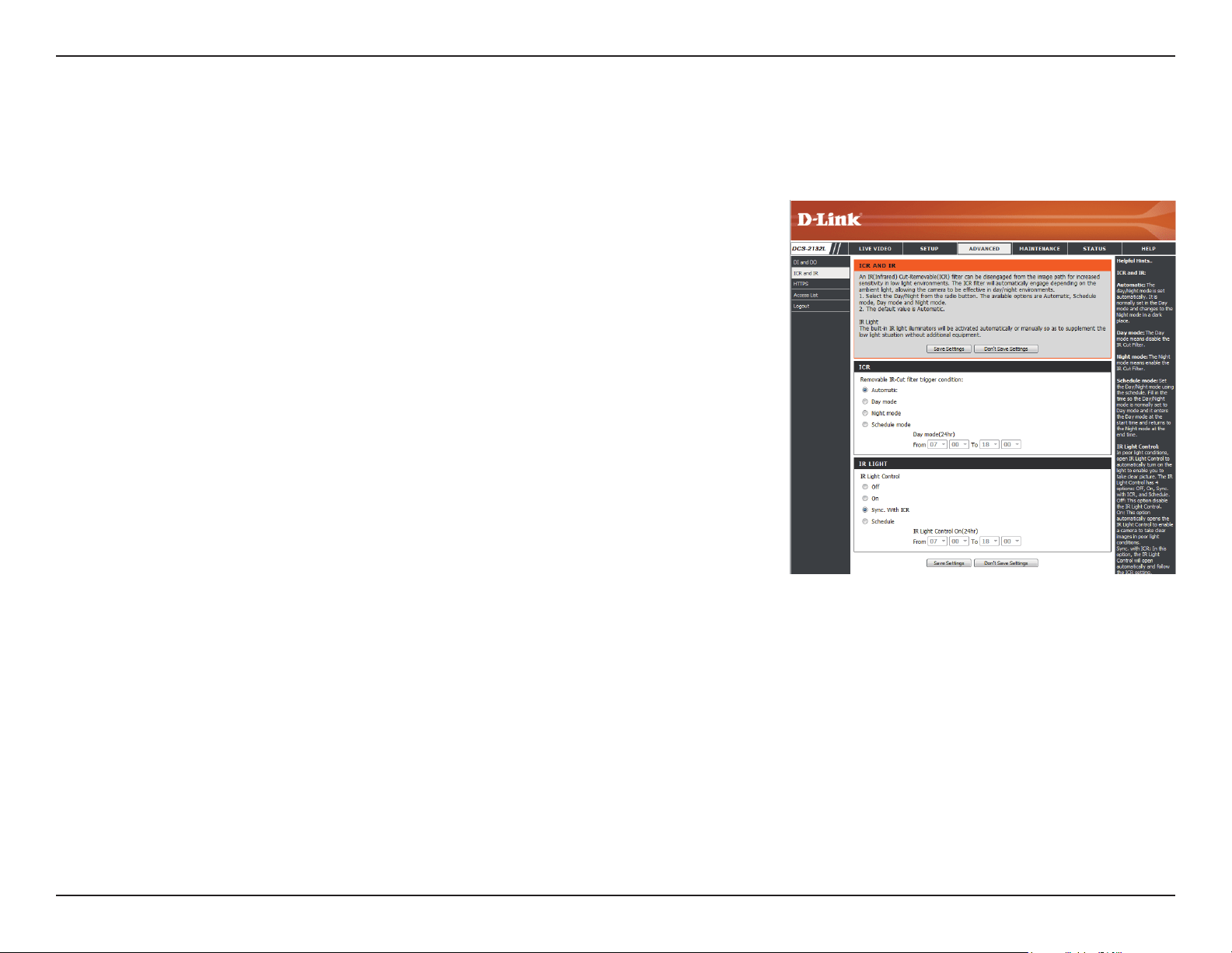
ICR and IR
Here you can congure the ICR and IR settings. An IR(Infrared) Cut-Removable(ICR) lter can be disengaged for increased sensitivity in low light
environments.
Automatic:
Day Mode:
Night Mode:
Schedule Mode:
IR Light Control:
O:
On:
Sync:
Schedule:
The Day/Night mode is set automatically. Generally, the
camera uses Day mode and switches to Night mode
when needed.
Day mode enables the IR Cut Filter.
Night mode disables the IR Cut Filter.
Set up the Day/Night mode using a schedule. The camera
will enter Day mode at the starting time and return to
Night mode at the ending time.
The camera can enable or disable the IR (infrared) light
according to your preferences. This setting provides
additional controls depending on your specic application.
The IR light will always be o.
The IR light will always be on.
The IR light will turn on when the ICR sensor is on.
The IR light will turn on or o according to the schedule
that you specify below.
69D-Link DCS-2132L User Manual
Section 4: Conguration
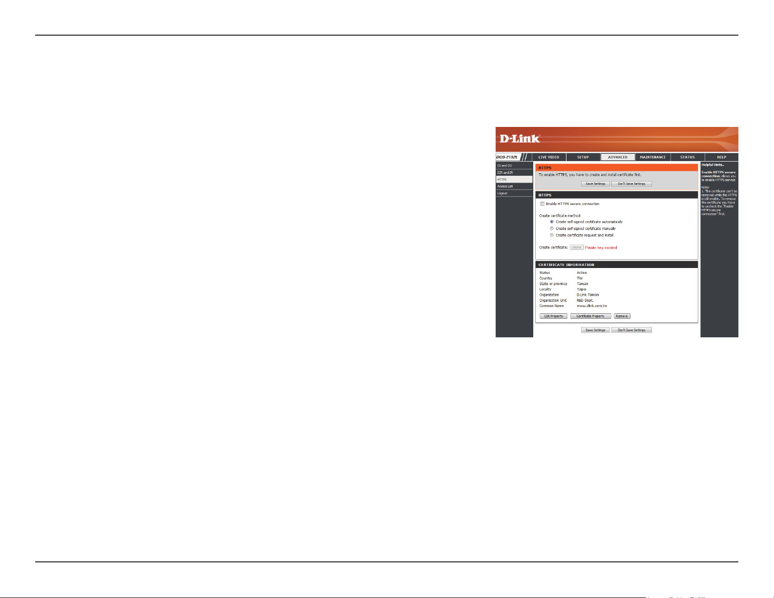
HTTPS
This page allows you to install and activate an HTTPS certicate for secure access to your camera. After making any changes, click the Save Settings
button to save your changes.
Enable HTTPS Secure Connection:
Create Certicate Method:
Status:
Note:
Enable the HTTPS service.
Choose the way the certicate should be created. Three
options are available:
Create a self-signed certicate automatically
Create a self-signed certicate manually
Create a certicate request and install
Displays the status of the certicate.
The certicate cannot be removed while the HTTPS is
still enabled. To remove the certicate, you must rst
uncheck Enable HTTPS secure connection.
70D-Link DCS-2132L User Manual
Section 4: Conguration
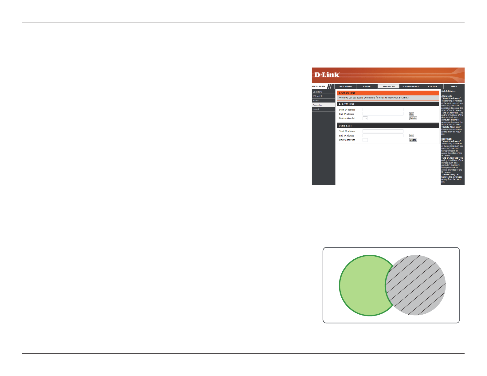
Access List
Here you can set access permissions for users to view your DCS-2132L.
Allow list:
Start IP address:
End IP address:
Delete allow list:
Deny list:
Delete deny list:
The list of IP addresses that have the access right to the
camera.
The starting IP Address of the devices (such as a computer)
that have permission to access the video of the camera.
Click Add to save the changes made.
Note: A total of seven lists can be congured for both
columns.
The ending IP Address of the devices (such as a computer)
that have permission to access the video of the camera.
Remove the customized setting from the Allow List.
The list of IP addresses that have no access rights to the
camera.
Remove the customized setting from the Delete List.
For example:
When the range of the Allowed List is set from 1.1.1.0
to 192.255.255.255 and the range of the Denied List is
set from 1.1.1.0 to 170.255.255.255. Only users with IPs
located between 171.0.0.0 and 192.255.255.255 can
access the Network Camera.
Alowed
List
Denied
List
71D-Link DCS-2132L User Manual
Section 4: Conguration
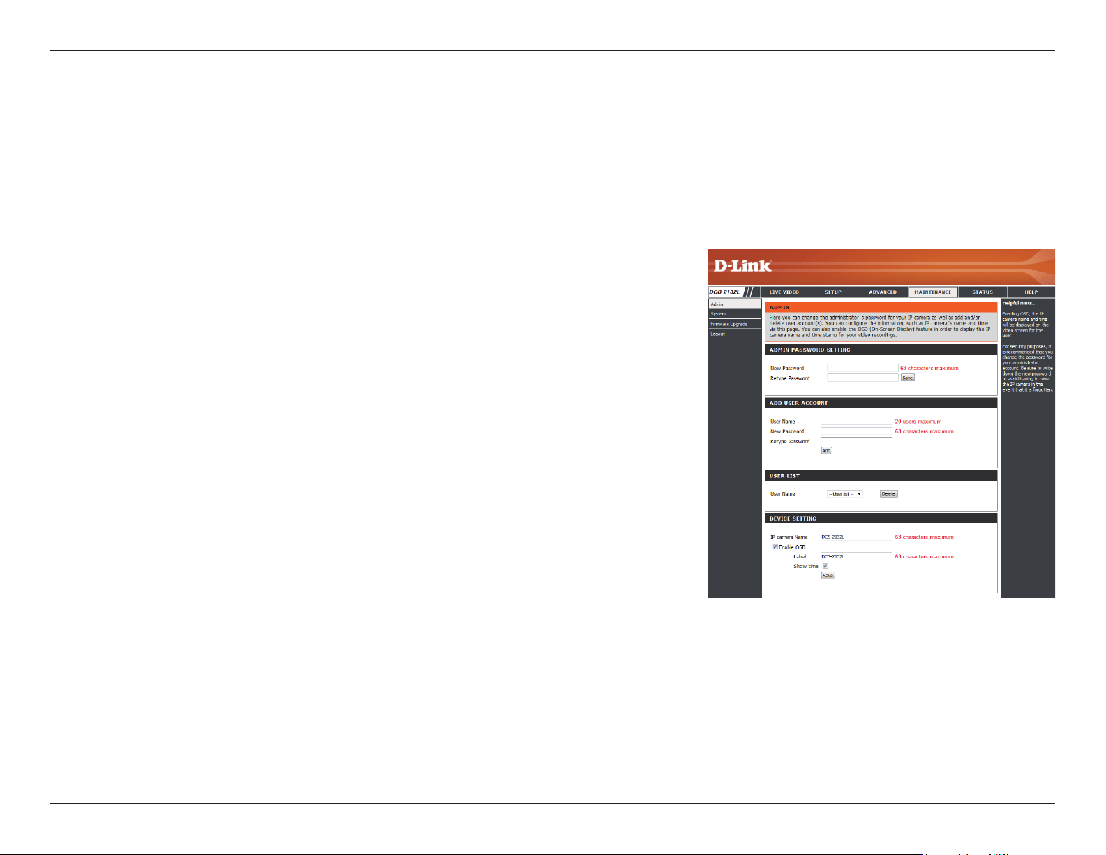
Maintenance
You may modify the name and administrator’s password of your camera, as well as add and manage the user accounts for accessing the camera.
You may also use this section to create a unique name and congure the OSD settings for your camera.
Admin Password Setting:
Add User Account:
User Name:
Password:
User List:
Camera Name:
Enable OSD:
Label:
Show Time:
Set a new password for the administrator’s account.
Add new user account.
The user name for the new account.
The password for the new account.
All the existing user accounts will be displayed here. You
may delete accounts included in the list, but you may
want to reserve at least one as a guest account.
Create a unique name for your camera that will be added
to the le name prex when creating a snapshot or a
video clip.
Select this option to enable the On-Screen Display
feature for your camera.
Enter a label for the camera, which will be shown on the
OSD when it is enabled.
Select this option to enable the time-stamp display on
the video screen.
Device Management
72D-Link DCS-2132L User Manual
Section 4: Conguration
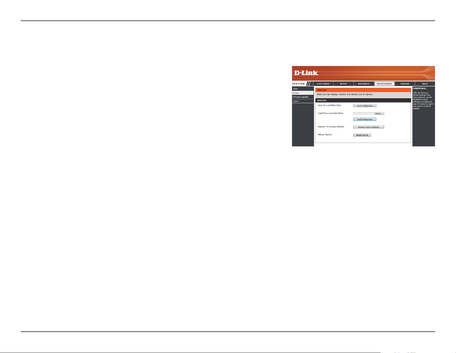
System
In this section, you may backup, restore and reset the camera conguration, or reboot the camera.
Save To Local Hard Drive:
Local From Local Hard Drive:
Restore to Factory Default:
Reboot Device:
You may save your current camera conguration as a le
on your computer.
Locate a pre-saved conguration by clicking Browse and
then restore the pre-dened settings to your camera by
clicking Load Conguration.
You may reset your camera and restore the factory
settings by clicking Restore Factory Defaults.
This will restart your camera.
73D-Link DCS-2132L User Manual
Section 4: Conguration
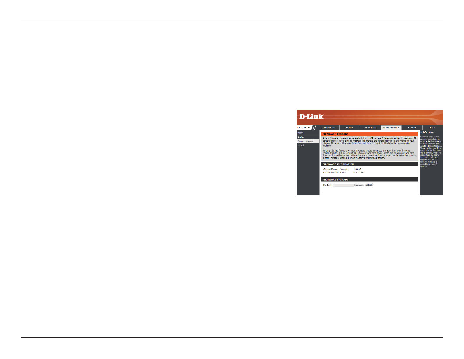
Firmware Upgrade
The camera's current rmware version will be displayed on this screen. You may visit the D-Link Support Website to check for the latest available
rmware version.
To upgrade the rmware on your DCS-2132L, please download and save the latest rmware version from the D-Link Support Page to your local
hard drive. Locate the le on your local hard drive by clicking the Browse button. Select the le and click the Upload button to start upgrading the
rmware.
Current Firmware Version:
Current Product Name:
File Path:
Upload:
Displays the detected rmware version.
Displays the camera model name.
Locate the le (upgraded rmware) on your hard drive
by clicking Browse.
Uploads the new rmware to your camera.
74D-Link DCS-2132L User Manual
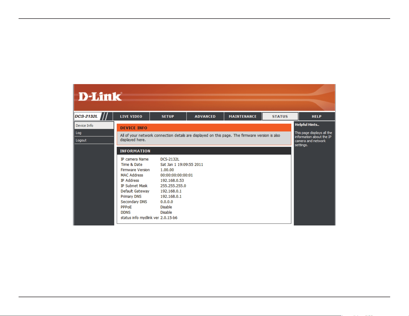
Section 4: Conguration
Status
This page displays detailed information about your device and network connection.
Device Info
75D-Link DCS-2132L User Manual
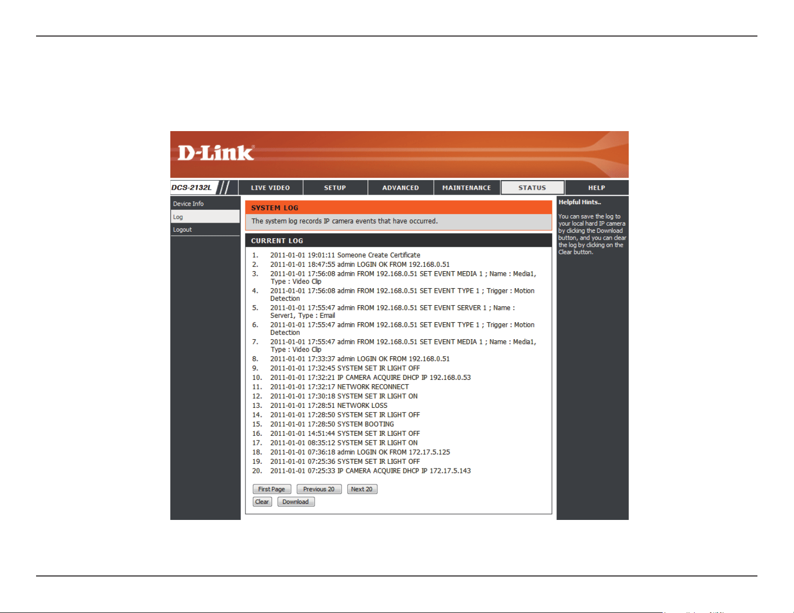
Section 4: Conguration
This page displays the log information of your camera. You may download the information by clicking Download. You may also click Clear to delete
the saved log information.
Logs
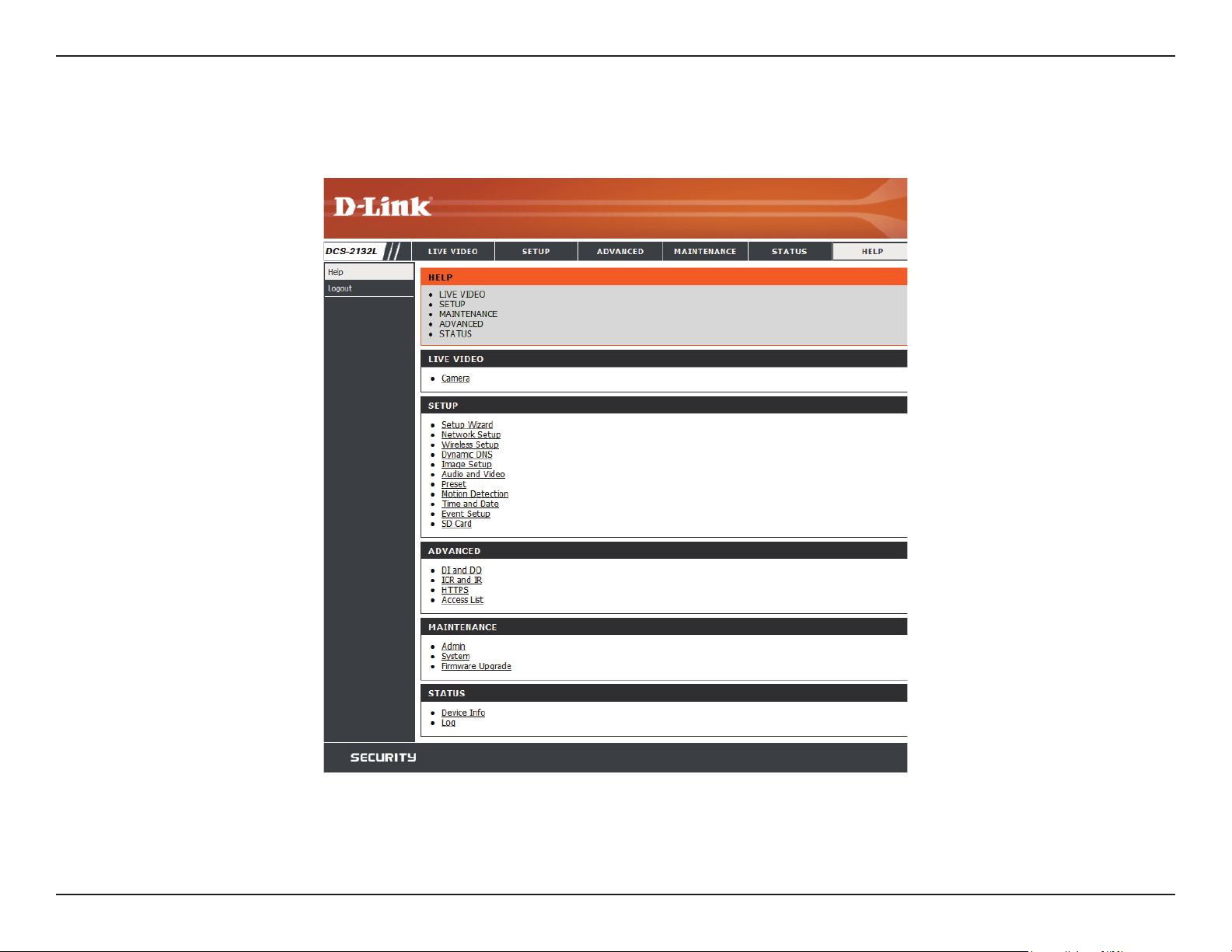
76D-Link DCS-2132L User Manual
Section 4: Conguration
This page provides helpful information regarding camera operation.
Help
77D-Link DCS-2132L User Manual
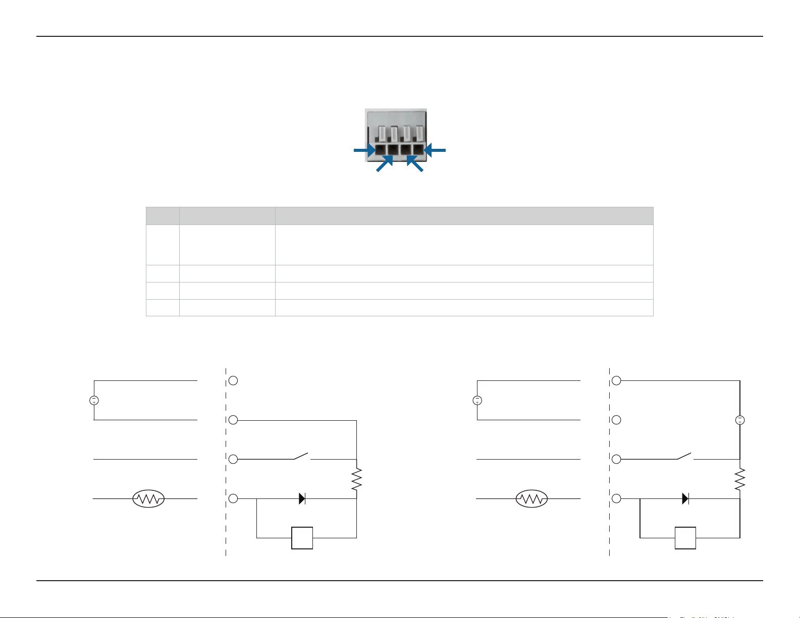
Appendix A: DI/DO Specications
DI/DO Specications
Pin 1 Pin 4
Pin 3Pin 2
PIN FUNCTION
NOTE
1 Digital Out (DO) Uses an open-drain NFET transistor with the source connected to GND in camera. If used
with an external relay, a diode must be connected in parallel with the load for protection
against voltage transients. Max loading is 100 mA.
2 Digital In (DI) A switch from DI to DC 5 V, activated by setting NO. or NC.
3 DC5V OUTPUT DC 5 V Output / Max. 100 mA
4 GND GND
Internal 5V Power External 3~12V Power
DO
DI
5V
DND
N.C / N.O
100 mA
ALARM
Reed switch
Diode
DC Power 5V
R
DO
DI
5V
DND
N.C / N.O
ALARM
Reed switch
Diode
DC Power 5V
R
DC Power 3V~12V
100 mA

78D-Link DCS-2132L User Manual
Appendix B: Technical Specications
Technical Specications
Camera Camera Hardware
Prole
1/4” Megapixel progressive CMOS sensor
5 meter IR illumination distance
Minimum illumination: 0 lux with IR LED on
Built-in Infrared-Cut Removable (ICR) Filter module
Built-in PIR sensor (5 meter)
Built-in microphone and speaker
10x digital zoom
Focal length: 3.45 mm
Aperture: F2.0
Angle of view:
(H) 57.8°
(V) 37.8°
(D) 66°
Image Features
Congurable image size, quality, frame rate, and bit rate
Time stamp and text overlays
Congurable motion detection windows
Congurable privacy mask zones
Congurable shutter speed, brightness, saturation, contrast,
and sharpness
Video Compression
Simultaneous H.264/MPEG-4/MJPEG format compression
H.264/MPEG-4 multicast streaming
JPEG for still images
Video Resolution 16:9 - 1280 x 800, 1280 x 720, 800 x 450, 640 x 360, 480 x 270, 320
x 176, 176 x 144
4:3 - 1024 x 768, 800 x 600, 640 x 480, 480 x 360, 320 x 240, 176 x
144
Audio Support G.726, G.711
External Device
Interface
10/100 BASE-TX Fast Ethernet port
IEEE 802.11n 2.4GHz single band wireless
DI/DO port
MicroSD/SDHC card slot
Network Network Protocols
IPv6
IPv4
TCP/IP
UDP
ICMP
DHCP client
NTP client (D-Link)
DNS client
DDNS client (D-Link)
SMTP client
FTP client
HTTP / HTTPS
Samba Client
PPPoE
UPnP port forwarding
RTP / RTSP/ RTCP
IP ltering
QoS
CoS
Multicast
IGMP
ONVIF compliant
Security
Administrator and user group protection
Password authentication
HTTP and RTSP digest encryption

79D-Link DCS-2132L User Manual
Appendix B: Technical Specications
System
Management
System
Requirements for
Web Interface
Operating System: Microsoft Windows 7/Vista/XP/2000
Browser: Internet Explorer, Firefox, Netscape, Opera
Event Management
Motion detection
Event notication and uploading of snapshots/video clips via
e-mail or FTP
Supports multiple SMTP and FTP servers
Multiple event notications
Multiple recording methods for easy backup
Remote
Management
Take snapshots/video clips and save to local hard drive or NAS
via web browser
Conguration interface accessible via web browser
Mobile Support Windows 7/Vista/XP system, Pocket PC, or mobile phone mydlink mobile app for iOS and Android mobile devices
D-ViewCam™ System
Requirements
Operating System: Microsoft Windows 7/Vista/XP
Web Browser: Internet Explorer 7 or higher
Protocol: Standard TCP/IP
D-ViewCam™
Software Functions
Remote management/control of up to 32 cameras
Viewing of up to 32 cameras on one screen
Supports all management functions provided in web interface
Scheduled motion triggered, or manual recording options
General Weight
116g
External Power
Adaptor
Input: 100 to 240 V AC, 50/60 Hz Output: 5 V DC, 1.2 A, 50/60 Hz
Power Consumption
3.65 watts
Temperature
Operating: 0 to 40 °C (32 to 104 °F) Storage: -20 to 70 °C (-4 to 158 °F)
Humidity Operating: 20% to 80% non-condensing Storage: 5% to 95% non-condensing
Certications
CE
CE LVD
FCC
C-Tick
80D-Link DCS-2132L User Manual
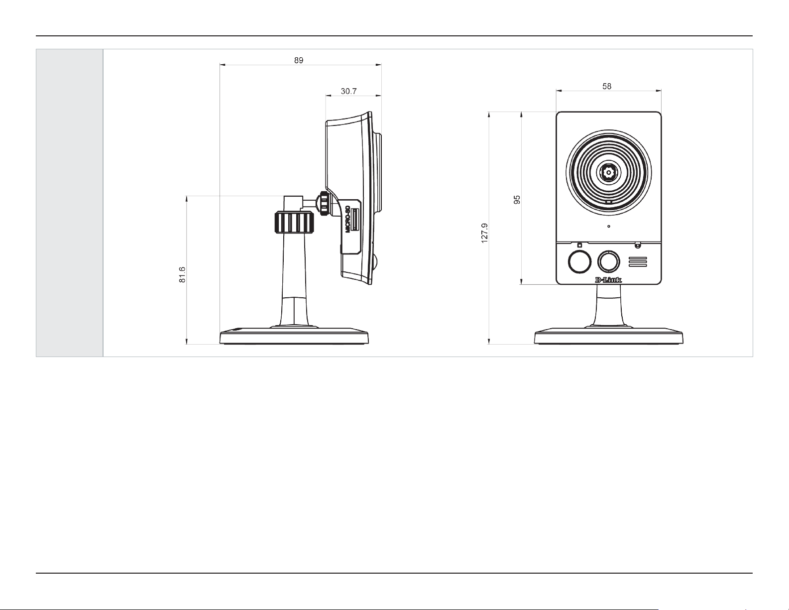
Appendix B: Technical Specications
Dimensions
•

81D-Link DCS-2132L User Manual
Appendix C: Safety Statements
CE Mark Warning:
This is a Class B product. In a domestic environment, this product may cause radio interference, in which case the user may be required to take
adequate measures.
FCC Statement:
This equipment has been tested and found to comply with the limits for a Class B digital device, pursuant to part 15 of the FCC Rules. These limits are
designed to provide reasonable protection against harmful interference in a residential installation. This equipment generates, uses, and can radiate
radio frequency energy and, if not installed and used in accordance with the instructions, may cause harmful interference to radio communication.
However, there is no guarantee that interference will not occur in a particular installation. If this equipment does cause harmful interference to radio
or television reception, which can be determined by turning the equipment o and on, the user is encouraged to try to correct the interference by
one or more of the following measures:
• Reorient or relocate the receiving antenna.
• Increase the separation between the equipment and receiver.
• Connect the equipment into an outlet on a circuit dierent from that to which the receiver is connected.
• Consult the dealer or an experienced radio/TV technician for help.
FCC Caution:
Any changes or modications not expressly approved by the party responsible for compliance could void the user’s authority to operate this
equipment.
This device complies with Part 15 of the FCC Rules. Operation is subject to the following two conditions:
(1) This device may not cause harmful interference, and (2) this device must accept any interference received, including interference that may cause
undesired operation.
Safety Statements

82D-Link DCS-2132L User Manual
Appendix C: Safety Statements
IMPORTANT NOTICE:
FCC Radiation Exposure Statement:
This equipment complies with FCC radiation exposure limits set forth for an uncontrolled environment. This equipment should be installed and
operated with minimum distance 20cm between the radiator & your body. This transmitter must not be co-located or operating in conjunction
with any other antenna or transmitter.
The availability of some specic channels and/or operational frequency bands are country dependent and are rmware programmed at the factory
to match the intended destination. The rmware setting is not accessible by the end user.
For detailed warranty information applicable to products purchased outside the United States, please contact the corresponding local D-Link
oce.
Industry Canada Notice:
This device complies with RSS-210 of the Industry Canada Rules. Operation is subject to the following two conditions:
(1) This device may not cause harmful interference, and (2) this device must accept any interference received, including interference that may cause
undesired operation.
IMPORTANT NOTE:
Radiation Exposure Statement:
This equipment complies with IC radiation exposure limits set forth for an uncontrolled environment. This equipment should be installed and
operated with minimum distance 20cm between the radiator & your body.
This device has been designed to operate with an antenna having a maximum gain of 2 dB. Antenna having a higher gain is strictly prohibited per
regulations of Industry Canada. The required antenna impedance is 50 ohms.