Loading ...
Loading ...
Loading ...
12
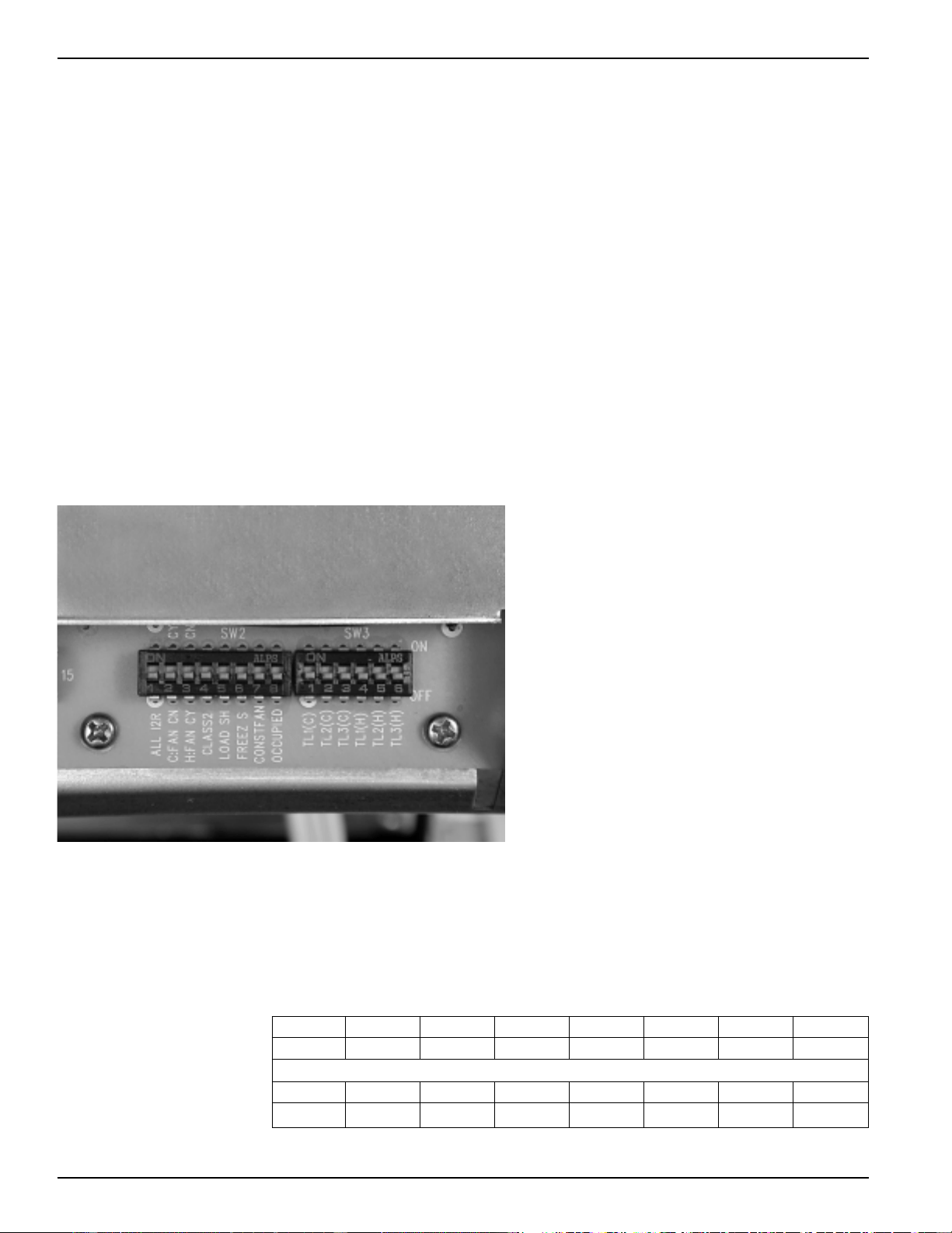
Auxiliary Control Switches
These switches are located behind the room cabinet under the control panel.
2500 and 3500 Series
Switches Description
(1) ALL I2R Heat pump override - Down - heat pump operation
Up - resistance heat only (not used on 2500 series)
(2) C:FAN Fan control for cooling operation - Down - Fan Continuous
Up - Fan Cycle
(3) H:FAN Fan control for heating operation - Down - Fan Cycle
Up - Fan Continuous
(4) CLASS 2 Remote Thermostat Mode Down - Unit Control
Up - Remote Thermostat
(5) LOAD SHED Load Shedding when connected to Central Desk Control System
Down - Fan shuts off with unit Up - Fan under “Smart Fan” settings
(6) FREEZ S Freeze Sentinel Override - Down - Freeze Sentinel ON
Up - Freeze Sentinel OFF
(7) CONST FAN Constant Fan - Fan runs when unit is in STOP mode
(8) OCCUPIED Occupancy Sensor Mode - Down - Unit Control
Up - Occupancy Sensor Connected
Temp L1 - Temp L3 Cooling temperature limiting (See table at bottom of page)
Temp L4 - Temp L6 Heating temperature limiting (See table at bottom of page)
Cooling Temperature Limits
Switches Up NONE 1 1,2 2 2,3 1,2,3 1,3 3
60 64 66 68 70 72 74 76
Heating Temperature Limits
Switches Up 6 4,6 4,5,6 5,6 5 4,5 4 NONE
65 70 72 74 76 78 80 85
Cooling and Heating temperature limits are set independently.
Temperature limiting switches in factory set down position except as noted.
LC Minimum Temperature
LC Minimum Temperature
2020 Data Manual 2002 11/7/02 3:19 PM Page 12
Loading ...
Loading ...
Loading ...