Loading ...
Loading ...
Loading ...
36
Instructions for the installer
Suitable location
A gas-powered cooking appliance produces heat
and himidity in the area in which it is installed. For
this reason you should ensure good ventilation either
by keeping all natural air passages open or by in-
stalling an extractor hood with an ehaust flue (Fig.
3-4). Intensive and prolonged use of the appliance
may require extra ventilation, such the opening of
a window or an increase in speed of the electric fan,
if you have one.
If your appliance is not fitted with a thermocouple
(safety device) the ventilation hole shown in Fig. 3
should be at least 200 cm
2
.
Fig. 3
If a hood cannot be installed, an electric fan
should be fitted to an outside wall or window as
long there are air vents in the area.
The electric fan should be able to carry out a com-
plete change of air in the kitchen 3-5 times every
hour.
The installer should follow the relavant national
standards.
Fig. 4
Electrical connection
Check the data on the rating plate, located on the outside of the unit, to ensure that the
supply and input voltage are suitable.
Before connection, check the earthing system.
By Law, this appliance must be earthed. If this regulation is not complied with, the
Manufacturer will not be responsible for any damage caused to persons or property.
If a plug is not already attached, fit a plug appropriate to the load indicated on the rating
plate. The earth wire is coloured yellow/green.
Where the Hob is connected direct to the electricity supply, a circuit breaker must be
fitted with at least a 3 mm contact spacing when in the open position.
It if is necessary to replace the connecting cable, the earth wire (yellow/green) must,
by law, be approximately 10 mm longer than the live and neutral wires. Cable type
H05RR-F, H05VV-F, H05V2V2-F must be used.
The cables should be 1,5 mm
2
section for products with electrically heated elements,
35
INSTALLATION
Instructions for the installer
The Purchaser is responsible for the installation of the hob. The Manufacturer does not
accept any responsibility for any damage or loss resulting from incorrect installation,
and as such this will not covered by the Manufacturer’s Guarantee.
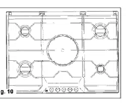
The hob may be installed in any worktop which is heat resistant to a temperature of
100° C, and has a thickness of 25 - 40 mm. The dimensions of the insert to be cut out
of the worktop are in shown in Fig. 1.
If the Hob is fitted next to a cabinet on either side,
the distance between the Hob and the cabinet
must be at least 150 mm (see Fig. 2); while the
distance between the hob and the rear wall must
be at least 55 mm.
When there is an accessible space between the
built-in hob and the cavity below, a dividing wall
made of insulating material should be inserted
(wood or a similar material).
The wall should be at least 10 mm away from bot-
tom of the drawer. (fig. 2)
The Hob unit is fitted by attaching the Fixing Clamps supplied, using the holes at the base
of the unit.
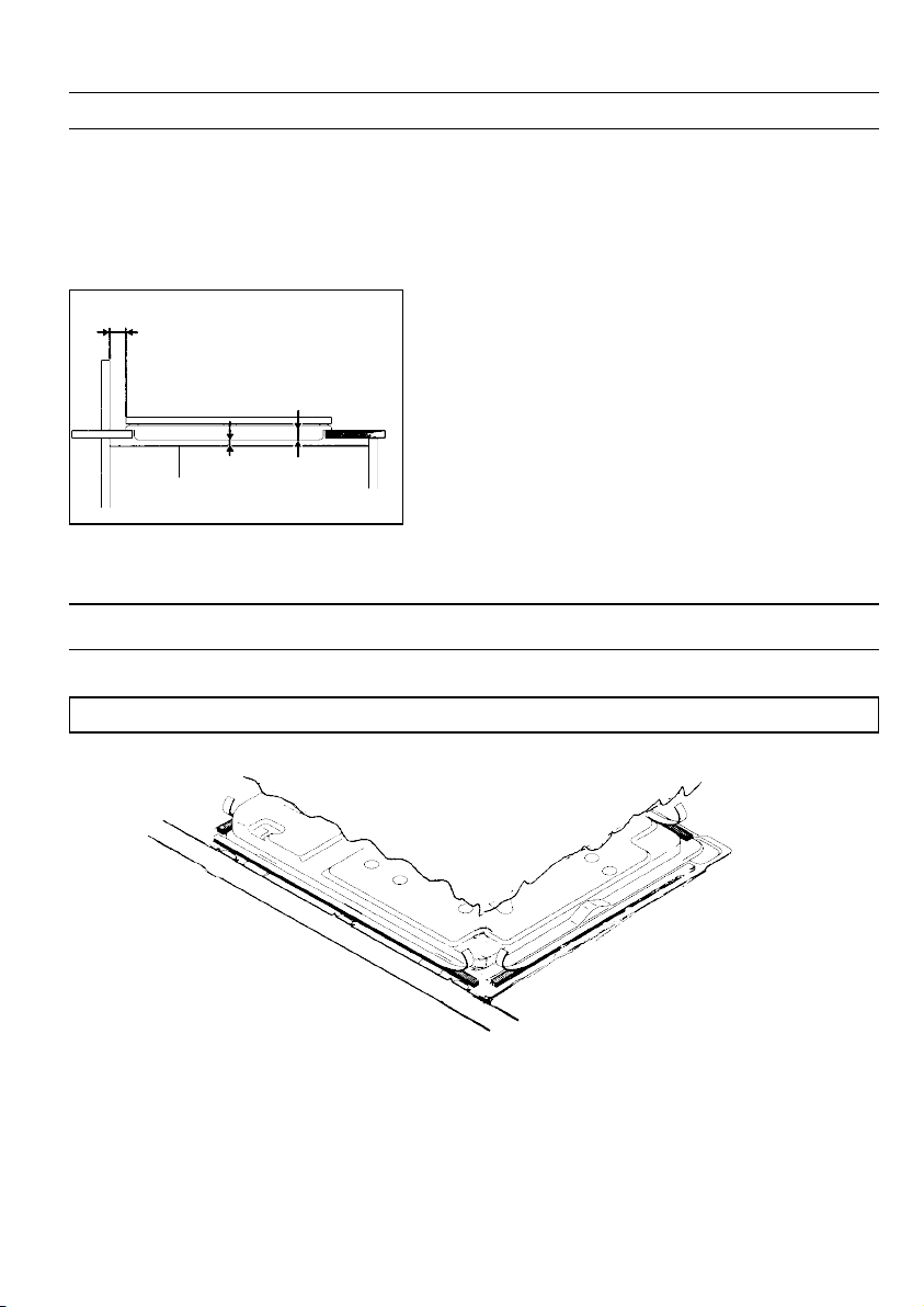
Applying the sealant
Important - The diagram below shows how the sealant should be applied.
This appliance has been designed for non-professional, i.e. domestic, use.
Appropriate checks and tests have ensured that, even in the most extreme conditions,
the temperatures reached are within acceptable limits. The Hob is thermally insula-
ted (in line with Regulation EN) and may be installed: next to panels higher than
the worktop, for type «Y», or next to panels not higher than the worktop for type
«X». See technical characteristics table «Degree of protection».
Fig. 2
Partition panel
150 mm
min.
30 mm
10 mm
Loading ...
Loading ...
Loading ...