
1
SERVICE MANUAL
SHARP CORPORATION
AH-X08BE/10BE/13BE
AY-X08BE/10BE/13BE
AY-X08BE-C/10BE-C
AU-X08BE/10BE/13BE
AE-X08BE/10BE/13BE
AE-X08BE-C/10BE-C
S7223AYX08BEC
SPLIT TYPE
ROOM AIR CONDITIONERS
In the interests of user-safety (Required by safety regulations in some
countries) the set should be restored to its original condition and only
parts identical to those specified should be used.
Page
SPECIFICATIONS ............................................................................................................................................. 2
EXTERNAL DIMENSIONS .................................................................................................................................5
WIRING DIAGRAMS ..........................................................................................................................................7
ELECTRICAL PARTS .......................................................................................................................................13
BLOCK DIAGRAM ............................................................................................................................................14
MICROCOMPUTER CONTROL SYSTEM .......................................................................................................16
FUNCTIONS .....................................................................................................................................................25
FUNCTION AND OPERATION OF PROTECTIVE PROCEDURES ................................................................ 31
BREAKDOWN DIAGNOSIS PROCEDURE .....................................................................................................33
REFRIGERATION CYCLE ..............................................................................................................................35
PERFORMANCE CURVES ..............................................................................................................................37
DISASSEMBLING PROCEDURE .....................................................................................................................39
OPTION ............................................................................................................................................................46
REPLACEMENT PARTS LIST .........................................................................................................................47
TABLE OF CONTENTS
INDOOR UNIT
AH-X08BE/10BE/13BE
AY-X08BE/10BE/13BE
AY-X08BE-C/10BE-C
OUTDOOR UNIT
AU-X08BE/10BE/13BE
AE-X08BE/10BE/13BE
AE-X08BE-C/10BE-C
MODELS

2
AH-X08BE/10BE/13BE
AY-X08BE/10BE/13BE
AY-X08BE-C/10BE-C
AU-X08BE/10BE/13BE
AE-X08BE/10BE/13BE
AE-X08BE-C/10BE-C
SPECIFICATIONS
MODEL
I
NDOOR UNIT
OUTDOOR UNIT
INDOOR UNIT
OUTDOOR UNIT
INDOOR UNIT
OUTDOOR UNIT
ITEMS AH-X08BE AU-X08BE AH-X10BE AU-X10BE AH-X13BE AU-X13BE
Cooling capacity
(Min. ~ Max.)
kW 2.2(0.9
_
2.7) 2.8(0.9
_
3.3) 3.6(0.9
_
4.2)
Moisture removal Liters/h 0.6 0.7 1.3
Electrical data
Phase Single
Rated frequency Hz 50
Rated voltage range V 198 to 264
Rated voltage V 220 - 240
Rated current A 3.4
_
3.1 4.3
_
4.0 5.5
_
5.1
Rated input W 730 930 1200
Power factor % 98
_
98 98
_
97 99
_
98
Type Hermetically sealed rotary type
Compressor Model 2RV110N5EA04 HV237A1-S15DK
Oil charge ATMOS M60 or SUNISO 4GDID 260 cm
3
SUNISO 4GSD 455 cc
Evaporator Bare tube type Grooved tube type Grooved tube type
Refrigerant system Condenser Louver Fin and Grooved tube type
Control Capillary tube
Refrigerant volume
550g 550g 830g
Noise level
High dB(A) 33 43 36 43 38 48
(at cooling)
Med. dB(A) 29 – 32 – 33 -
Low dB(A) 27 – 27 – 29 -
Fan system
Drive Direct drive
Air flow quantity High m
3
/min. 7.5 28 8.7 28 9.3 30
(at cooling) Med. m
3
/min. 6.8 – 7.8 – 8.1 –
Low m
3
/min. 6.0 – 6.0 – 6.6 –
Fan
Cross flow fan Propeller fan Cross flow fan Propeller fan Cross flow fan Propeller fan
Connections
Refrigerant coupling Flare type
Refrigerant tube size Gas, Liquid 3/8", 1/4" 1/2", 1/4"
Drain piping mm O.D ø 18
Others
Compressor: Thermal protector
Safety device Fan motors: Thermal fuse
Fuse, Micro computer control
Air filters Polypropylene net (Washable)
Width mm 815 780 815 780 815 780
Net dimensions Height mm 278 540 278 540 278 540
Depth mm 198 269 198 269 198 269
Net weight kg 9 31 9 33 10 38
Note: The condition of star " " marked item are ‘ISO5151’ : 1994(E), condition T1.
3
AH-X08BE/10BE/13BE
AY-X08BE/10BE/13BE
AY-X08BE-C/10BE-C
AU-X08BE/10BE/13BE
AE-X08BE/10BE/13BE
AE-X08BE-C/10BE-C
MODEL
I
NDOOR UNIT
OUTDOOR UNIT
INDOOR UNIT
OUTDOOR UNIT
ITEMS AY-X08BE AE-X08BE
AY-X08BE-C AE-X08BE-C
Cooling capacity
(Min. ~ Max.)
kW 2.2(0.7
_
2.7) 2.2(0.9
_
2.7)
Heating capacity
(Min. ~ Max.)
kW 3.2(0.7
_
3.6) 3.2(0.9
_
3.6)
Moisture removal(at cooling) Liters/h 0.7 0.7
Electrical data
Phase Single
Rated frequency Hz 50
Rated voltage range V 198 to 264
Rated voltage V 220 - 240
Cool A 3.4
_
3.1 3.4
_
3.1
Rated current Heat A 4.2
_
3.9 4.2
_
3.9
Cool W 730 730
Rated input Heat W 910 910
Cool % 98
_
98 98
_
98
Power factor Heat % 98
_
97 98
_
97
Type Hermetically sealed rotary type
Compressor Model HV166A1-S10DK 44A072QV2JD
Oil charge 455cc (SUNISO 4GSD)
280cc (SUNISO 4GSD-T)
Evaporator Louver Fin and Grooved tube type
Refrigerant system Condenser Corrugate Fin and Grooved tube type
Control Capillary tube
Refrigerant volume
760g 760g
De-lce system Micro computer controled reversed systems
Noise level
High dB(A) 33 43 33 43
(at cooling)
Med. dB(A) 29 – 29 –
Low dB(A) 27 – 27 –
Fan system
Drive Direct drive
Air flow quantity High m
3
/min. 7.5 28 7.5 28
(at cooling) Med. m
3
/min. 6.8 – 6.8 –
Low m
3
/min. 6.0 – 5.5 –
Fan
Cross flow fan Propeller fan Cross flow fan Propeller fan
Connections
Refrigerant coupling Flare type
Refrigerant tube size Gas, Liquid 3/8", 1/4"
Drain piping mm O.D ø 18
Others
Compressor: Thermal protector
Safety device Fan motors: Thermal fuse
Fuse, Micro computer control
Air filters Polypropylene net (Washable)
Width mm 815 780 815 780
Net dimensions Height mm 278 540 278 540
Depth mm 198 269 198 269
Net weight kg 9 35 9 36
Note: The condition of star "
" marked item are ‘ISO5151’ : 1994(E), condition T1.
4
AH-X08BE/10BE/13BE
AY-X08BE/10BE/13BE
AY-X08BE-C/10BE-C
AU-X08BE/10BE/13BE
AE-X08BE/10BE/13BE
AE-X08BE-C/10BE-C
MODEL
I
NDOOR UNIT
OUTDOOR UNIT
INDOOR UNIT
OUTDOOR UNIT
INDOOR UNIT
OUTDOOR UNIT
ITEMS AY-X10BE AE-X10BE
AY-X10BE-C AE-X10BE-C
AY-X13BE AE-X13BE
Cooling capacity
(Min. ~ Max.)
kW 2.8(0.7
_
3.3) 2.8(0.9
_
3.3) 3.6(0.9
_
4.2)
Heating capacity
(Min. ~ Max.)
kW 3.7(0.7
_
5.0) 3.7(0.9
_
5.0) 4.8(1.0
_
6.2)
Moisture removal(at cooling) Liters/h 0.8 0.8 1.3
Electrical data
Phase Single
Rated frequency Hz 50
Rated voltage range V 198 to 264
Rated voltage V 220 - 240
Cool A 4.3
_
4.0 4.3
_
4.0 5.5
_
5.1
Rated current Heat A 4.8
_
4.4 4.8
_
4.4 6.8
_
6.2
Cool W 930 930 1200
Rated input Heat W 1050 1050 1480
Cool % 98
_
97 98
_
97 99
_
98
Power factor Heat % 99
_
99 99
_
99 99
_
99
Type Hermetically sealed rotary type
Compressor Model HV237A1-S15DK HV187X1-S12F3 HV237A1-S15DK
Oil charge 455cc (SUNISO 4GSD) 370cc (SUNISO 4GSD) 455cc (SUNISO 4GSD)
Evaporator Louver Fin and Grooved tube type
Refrigerant system Condenser Corrugate Fin and Grooved tube type
Control Capillary tube
Refrigerant volume
850g 850g 880g
De-lce system Micro computer controled reversed systems
Noise level
High dB(A) 36 43 36 43 38 48
(at cooling)
Med. dB(A) 32 – 32 – 33 -
Low dB(A) 27 – 27 – 29 -
Fan system
Drive Direct drive
Air flow quantity High m
3
/min. 9.8 27.7 9.8 27.7 9.3 30
(at cooling) Med. m
3
/min. 8.2 – 8.2 – 8.1 –
Low m
3
/min. 6.1 – 6.1 – 6.6 –
Fan
Cross flow fan Propeller fan Cross flow fan Propeller fan Cross flow fan Propeller fan
Connections
Refrigerant coupling Flare type
Refrigerant tube size Gas, Liquid 3/8", 1/4" 1/2", 1/4"
Drain piping mm O.D ø 18
Others
Compressor: Thermal protector
Safety device Fan motors: Thermal fuse
Fuse, Micro computer control
Air filters Polypropylene net (Washable)
Width mm 815 780 815 780 815 780
Net dimensions Height mm 278 540 278 540 278 540
Depth mm 198 269 198 269 198 269
Net weight kg 10 35 10 36 10 39
Note: The condition of star "
" marked item are ‘ISO5151’ : 1994(E), condition T1.

5
AH-X08BE/10BE/13BE
AY-X08BE/10BE/13BE
AY-X08BE-C/10BE-C
AU-X08BE/10BE/13BE
AE-X08BE/10BE/13BE
AE-X08BE-C/10BE-C
269
179.5
182.5
136
81
780
70
540
310
335
540
12
37.5
4.5
58
158
16
EXTERNAL DIMENSIONS
Figure E-1. INDOOR UNIT
Figure E-2. OUTDOOR UNIT
Length unit (mm)
19.5
58
CRMC-A442JBE0
R03(AAA) 2PCS.
SHARP CORPORATION
INVERTER AIR CONDITIONER
182
815
278
198
1100
6
AH-X08BE/10BE/13BE
AY-X08BE/10BE/13BE
AY-X08BE-C/10BE-C
AU-X08BE/10BE/13BE
AE-X08BE/10BE/13BE
AE-X08BE-C/10BE-C
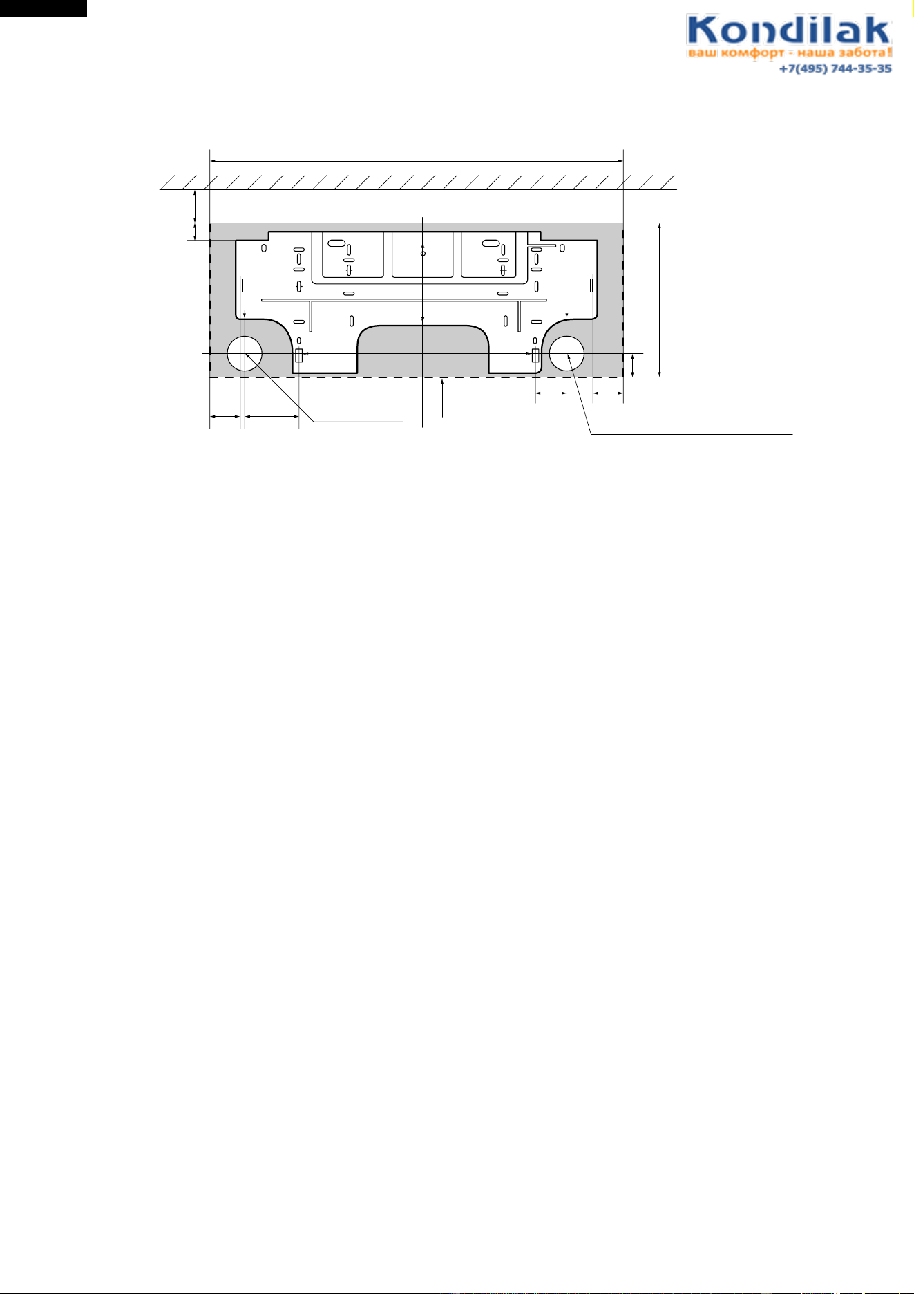
Figure E-3. INSTALLATION DIMENSIONS
815 (unit size)
More than 50mm
E
Center of wall hole:
Leftward piping
Center of wall hole: Backward piping
Outline of indoor unit
55 95
80 55
AJ
IF
E
D
D
FA
C
J
H
I
GB
21
278 (unit size)
38
Ceiling
E
7
AH-X08BE/10BE/13BE
AY-X08BE/10BE/13BE
AY-X08BE-C/10BE-C
AU-X08BE/10BE/13BE
AE-X08BE/10BE/13BE
AE-X08BE-C/10BE-C
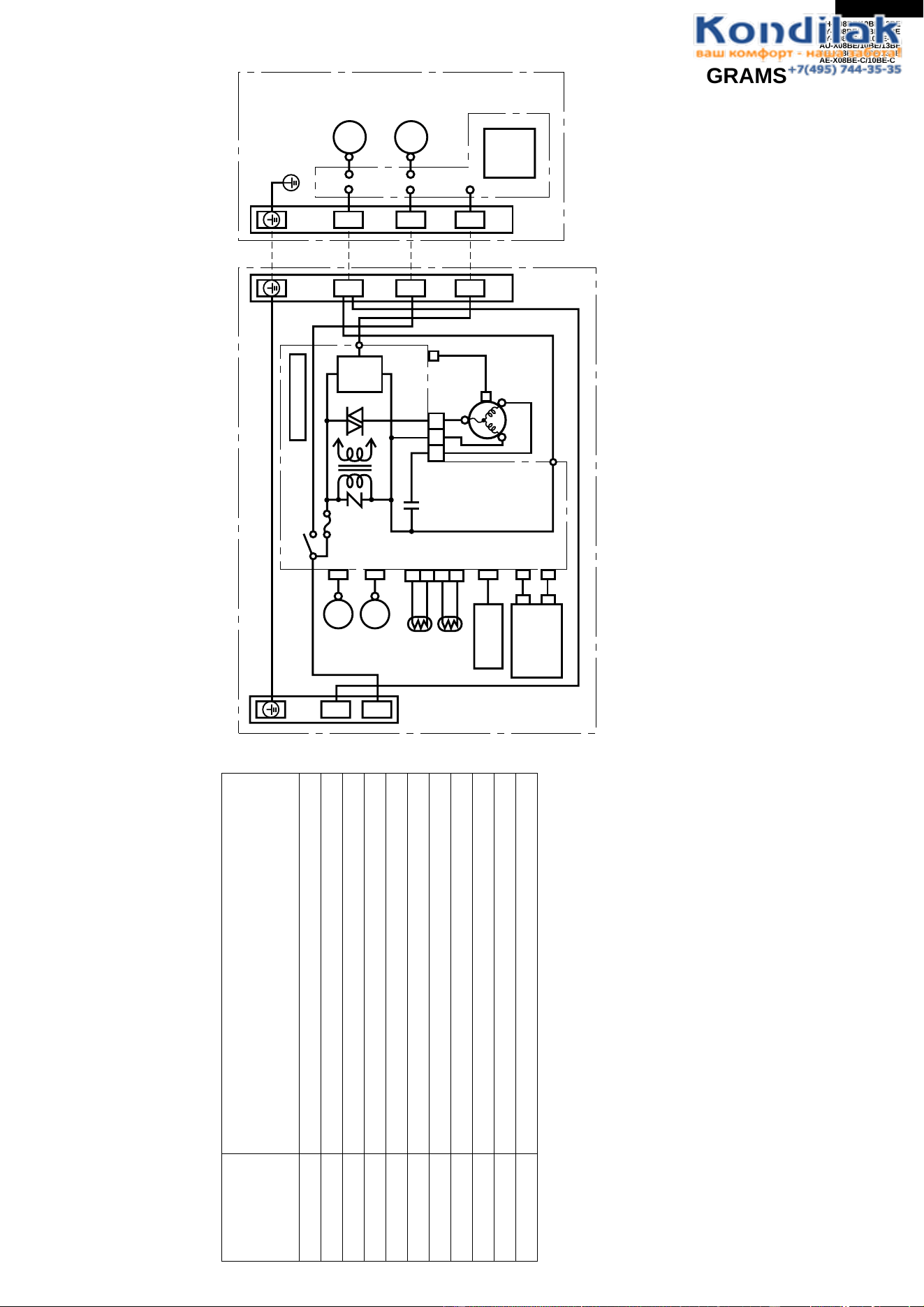
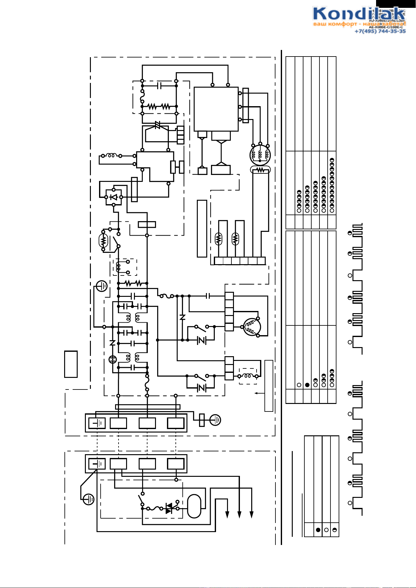
Figure W-1. Wiring Diagram for AH-X08BE/X10BE/X13BE and AY-X08BE/X08BE-C/X10BE/X10BE-C/X13BE
WIRING DIAGRAMS
TERMINAL BOARD 1
GREEN-YELLOW
POWER
SUPPLY
SINGLE
PHASE
INDOOR UNIT
OUTDOOR UNIT
BROWN In Out
C1
RY1
WPE1
250V
3A
CONTROL BOARD UNIT
LOUVER
(UPPER)
LOUVER
(LOWER)
ROOM TEMP.
THERMISTOR
PIPE TEMP.
THERMISTOR
TH1
TH2
3
4
1
2
CN3
YELLOW
ORANGE
RECEIVER
BOARD UNIT
DISPLAY
BOARD
UNIT
BCN2
BCN3
CN101
CN102
CN2
CN7
BCN1
TRANS1
SSR1
S
SERIAL
SIGNAL
CIRCUIT
FAN MOTOR
CAPACITOR
430V 2µF
CN6
CN1
TERMINAL BOARD 2
TERMINAL BOARD
BLACK
RED
BLUE
BLUE
5
3
1
N
BLACK
FAN MOTOR
BLUE
RED
COMPRESSOR
FAN MOTOR
UNIT
TO
UNIT
CORD
CONTROL
BOARD
UNIT
N
1
11
NN
22
R.P.M.
SIGNAL
INTERNAL
THERMAL
FUSE
LED INDICATION FOR SELF-DIAGNOSIS
Abnormal contents
Temperature
Indicator
Blinking No.
1
2
3
4
5
6
7
14
17
18
19
Short circuit of the outdoor thermistor
Overheat of the compressor
Abnormal AC current
Compressor lock
Open circuit of the outdoor thermistor
AC overcurrent
Power module
(
IPM
)
abnormality
Open circuit of serial signal line
Short circuit of serial signal line
Abnormal fan motor of indoor unit
Abnormal power factor module
(
AFM
)
Indication of the abnormal condition >
LED indicator will blink, if the set
is in abnormal condition.
M
M
M
M
8
AH-X08BE/10BE/13BE
AY-X08BE/10BE/13BE
AY-X08BE-C/10BE-C
AU-X08BE/10BE/13BE
AE-X08BE/10BE/13BE
AE-X08BE-C/10BE-C
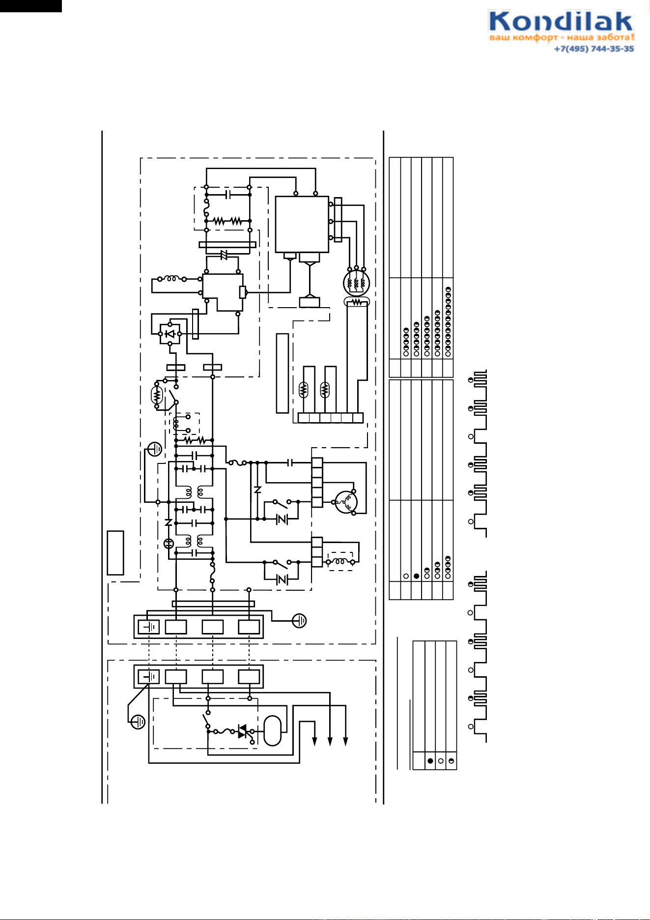
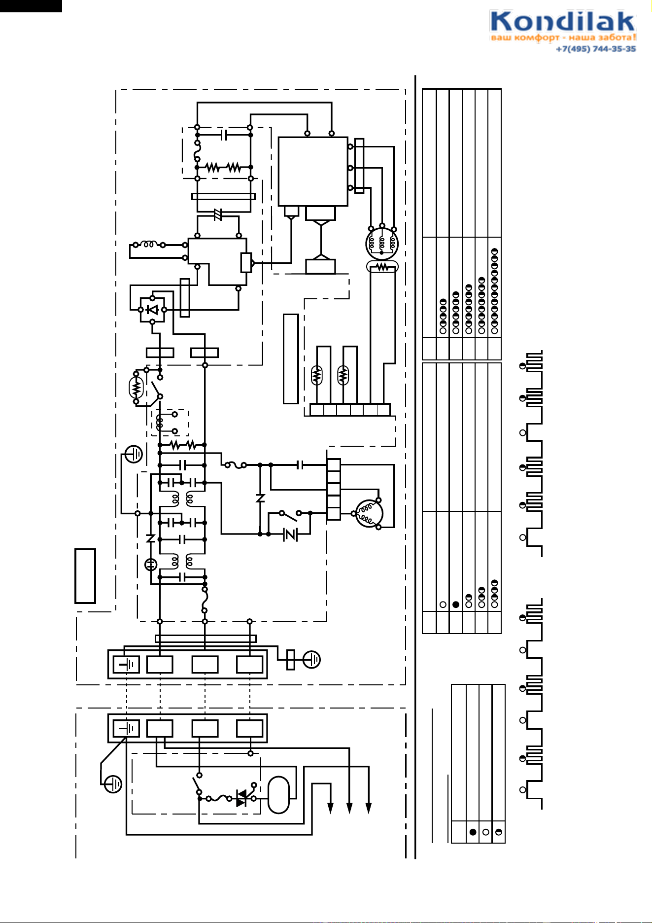
Figure W-2. Wiring Diagram for AE-X08BE/X10BE
+
+
-
-
+
+-
-
+
+
-
-
N
1
2
INDOOR UNIT
TERMINAL
BOARD
CONTROL
BOARD
UNIT
POWER
SUPPLY
FAN
MOTOR
TERMINAL BOARD
UNIT TO UNIT CORD
SINGLE PHASE
220-240V 50Hz
BL
T2
BR
T3
RE
FC3
FC4
BULK HEAD
RE
T1
WPE1
C1
C2
15A
250V
SA1
RY1
T4
G(Y)
L1
CN11
CT1
The voltage is high at C8 (electronic capacitors) on outdoor unit.
For mentenance discharge at C8 to prevent electric shock.
In case that WPE2 has been fused, the voltage is kept high at C8.
CAUTION
BK
:
BLACK RE
:
RED YE
:
YELLOW
BL
:
BLUE WH
:
WHITE G:GREEN
BR
:
BROWN OR
:
ORANGE
GR
:
GRAY G
(
Y
):
GREEN-YELLOW
U
(
R
)
V
(
S
)
W
(
C
)
BL
GR
OR
FAN
MOTOR
BL
BL
PTC
MRY1
IN OUT
GR
T6
T5
BK
FC6
FC7
FC5
T9
T7
T8
YE
WH WH
RERE
C8
OUTDOOR UNIT
POWER
TRANSISTOR
MODULE
(
QM1
)
UVW
RE
WH
BK
COMPRESSOR
THERMISTOR
PIPE TEMP.
THERMISTOR
OUTDOOR
TEMP.
THERMISTOR
COMPRESSOR TEMP.
CN8
TH2
TH1
TH3
RE
OR
G
3
1
3
1
5
LED INDICATION OF SELF-DIAGNOSIS
ON OUTDOOR UNIT
LED BLINKING
LED turns on
Slow flashing
(
1 time for 2 seconds
)
Quick flashing
(
3 times for 2 seconds
)
Example: NO.2 Compressor lock
on
off
1.0sec 0.6sec 1.0sec 0.6sec 1.0sec 0.6sec
NO.3 Overheat of the compressor
1.0sec 0.6sec 0.6sec 1.0sec 0.6sec 0.6sec
1
2
3
4
5
NO. LED indication pattern
Mulfunction part or abnormal condition
Normal
Compressor lock
Abnormal signal line
Overheat of the compressor
QM1(IPM) Abnormality
Short circuit of the thermistor
7
8
6
NO. LED indication pattern
Mulfunction part or abnormal condition
Open circuit of the thermistor
AC overcurrent
9
Power factor module error
AC abnormal current
BK
1
2
3
4
5
6
NR1
NR2
CNR1
RY2
CNR2
N
1
2
L3
L4
WPE3
3A
250V
CN3CN4
CONTROL BOARD UNIT
DIODE BRIDGE
DB1
BL
C5
WPE2
10A
250V
BL
BR
FC2
BL
YE
FC1
T10
C10
~~
C
AM
4 WAY
VALVE
except cooling only models
ACTIVE
FILTER
AF1
I
I
0
0
LL
CONTROL
BOX
FAN MOTOR
CAPACITOR
1.5
µ
F 430V
C8: 1200
µ
F 420V
C31
9
AH-X08BE/10BE/13BE
AY-X08BE/10BE/13BE
AY-X08BE-C/10BE-C
AU-X08BE/10BE/13BE
AE-X08BE/10BE/13BE
AE-X08BE-C/10BE-C
Figure W-3. Wiring Diagram for AE-X08BE-C
+
-
+
-
N
1
2
INDOOR UNIT
TERMINAL
BOARD
CONTROL
BOARD
UNIT
POWER
SUPPLY
FAN
MOTOR
TERMINAL BOARD
UNIT TO UNIT CORD
SINGLE PHASE
220-240V 50Hz
BL
T2
BR
T3
RE
FC4
BULK HEAD
RE
T1
WPE1
C1
C2
C3
C4
C33
C34
15A
250V
SA1
RY1
T4
CN11
CT1
The voltage is high at C8 (electronic capacitors) on outdoor unit.
For mentenance discharge at C8 to prevent electric shock.
In case that WPE2 has been fused, the voltage is kept high at C8.
CAUTION
BK
:
BLACK RE
:
RED YE
:
YELLOW
BL
:
BLUE WH
:
WHITE G:GREEN
BR
:
BROWN OR
:
ORANGE
GR
:
GRAY G
(
Y
):
GREEN-YELLOW
BL
GR
G
(
Y
)
G
(
Y
)
FAN
MOTOR
BL
PTC1
MRY1
IN OUT
GR
T6
T5
BK
T9
T7
T8
YE
RE
C8
OUTDOOR UNIT
POWER
TRANSISTOR
MODULE
(
QM1
)
UVW
RE
WH
BK
COMPRESSOR
THERMISTOR
PIPE TEMP.
THERMISTOR
OUTDOOR
TEMP.
THERMISTOR
COMP. TEMP.
CN8
TH2
TH1
TH3
RE
OR
G
3
1
5
LED INDICATION OF SELF-DIAGNOSIS
ON OUTDOOR UNIT
LED BLINKING
LED turns on
Slow flashing
(
1 time for 2 seconds
)
Quick flashing
(
3 times for 2 seconds
)
Example: NO.2 Compre ssor lock
on
off
1.0sec 0.6sec 1.0sec 0.6sec 1.0sec 0.6sec
NO.3 Overheat of the compressor
1.0sec 0.6sec 0.6sec 1.0sec 0.6sec 0.6sec
1
2
3
4
5
NO. LED indication pattern
Mulfunction part or abnormal condition
Normal
Compressor lock
Abnormal signal line
Overheat of the compressor
Power module
(
QM1
)
abnornality
Short circuit of the thermistor
7
8
6
NO. LED indication pattern
Mulfunction part or abnormal condition
Open circuit of the thermistor
AC overcurrent
AC abnormal current
BK
1
2
3
4
5
6
NR1
NR2
CNR1
N
1
2
L3
L4
WPE3
3A
250V
CN3
CONTROL BOARD UNIT
DIODE BRIDGE
DB1
BL
C5
WPE2
10A
250V
BL
OR
BL
YE
FC1
T10
C10
C
AM
CONTROL
BOX
FAN MOTOR
CAPACITOR
1.5
μ
F 430V
C31
+
-
L1
WH
C8:1000
μ
F 420V
BL
〜〜
9
Power factor module error
R
C
S
FC6
FC7
AF1
L-
L+
I-
I+
ACTIVE
FILTER
FC5
O-
O+
WH
RE
BR
FC2
3
1
RY2
CNR2
4-WAY
VALVE
10
AH-X08BE/10BE/13BE
AY-X08BE/10BE/13BE
AY-X08BE-C/10BE-C
AU-X08BE/10BE/13BE
AE-X08BE/10BE/13BE
AE-X08BE-C/10BE-C
Figure W-4. Wiring Diagram for AE-X10BE-C
+
-
+
-
N
1
2
INDOOR UNIT
TERMINAL
BOARD
CONTROL
BOARD
UNIT
POWER
SUPPLY
FAN
MOTOR
TERMINAL BOARD
UNIT TO UNIT CORD
SINGLE PHASE
220-240V 50Hz
BL
T2
BR
T3
RE
FC4
BULK HEAD
RE
T1
WPE1
C1
C2
C3
C4
C33
C34
15A
250V
SA1
RY1
T4
CN11
CT1
The voltage is high at C8 (electronic capacitors) on outdoor unit.
For mentenance discharge at C8 to prevent electric shock.
In case that WPE2 has been fused, the voltage is kept high at C8.
CAUTION
BK
:
BLACK RE
:
RED YE
:
YELLOW
BL
:
BLUE WH
:
WHITE G:GREEN
BR
:
BROWN OR
:
ORANGE
GR
:
GRAY G
(
Y
):
GREEN-YELLOW
BL
GR
G
(
Y
)
G
(
Y
)
FAN
MOTOR
BL
PTC1
MRY1
IN OUT
GR
T6
T5
BK
T9
T7
T8
YE
RE
C8
OUTDOOR UNIT
POWER
TRANSISTOR
MODULE
(
QM1
)
UVW
RE
WH
BK
COMPRESSOR
THERMISTOR
PIPE TEMP.
THERMISTOR
OUTDOOR
TEMP.
THERMISTOR
COMP. TEMP.
CN8
TH2
TH1
TH3
RE
OR
G
3
1
5
LED INDICATION OF SELF-DIAGNOSIS
ON OUTDOOR UNIT
LED BLINKING
LED turns on
Slow flashing
(
1 time for 2 seconds
)
Quick flashing
(
3 times for 2 seconds
)
Example: NO.2 Compre ssor lock
on
off
1.0sec 0.6sec 1.0sec 0.6sec 1.0sec 0.6sec
NO.3 Overheat of the compressor
1.0sec 0.6sec 0.6sec 1.0sec 0.6sec 0.6sec
1
2
3
4
5
NO. LED indication pattern
Mulfunction part or abnormal condition
Normal
Compressor lock
Abnormal signal line
Overheat of the compressor
Power module
(
QM1
)
abnornality
Short circuit of the thermistor
7
8
6
NO. LED indication pattern
Mulfunction part or abnormal condition
Open circuit of the thermistor
AC overcurrent
AC abnormal current
BK
1
2
3
4
5
6
NR1
NR2
CNR1
N
1
2
L3
L4
WPE3
3A
250V
CN3
CONTROL BOARD UNIT
DIODE BRIDGE
DB1
BL
C5
WPE2
10A
250V
BL
OR
BL
YE
FC1
T10
C10
C
AM
CONTROL
BOX
FAN MOTOR
CAPACITOR
1.5
μ
F 430V
C31
+
-
L1
WH
C8:1000
μ
F 420V
BL
〜〜
9
Power factor module error
U(R)
W(C)
V(S)
FC6
FC7
AF1
L-
L+
I-
I+
ACTIVE
FILTER
FC5
O-
O+
WH
RE
BR
FC2
3
1
RY2
CNR2
4-WAY
VALVE
11
AH-X08BE/10BE/13BE
AY-X08BE/10BE/13BE
AY-X08BE-C/10BE-C
AU-X08BE/10BE/13BE
AE-X08BE/10BE/13BE
AE-X08BE-C/10BE-C
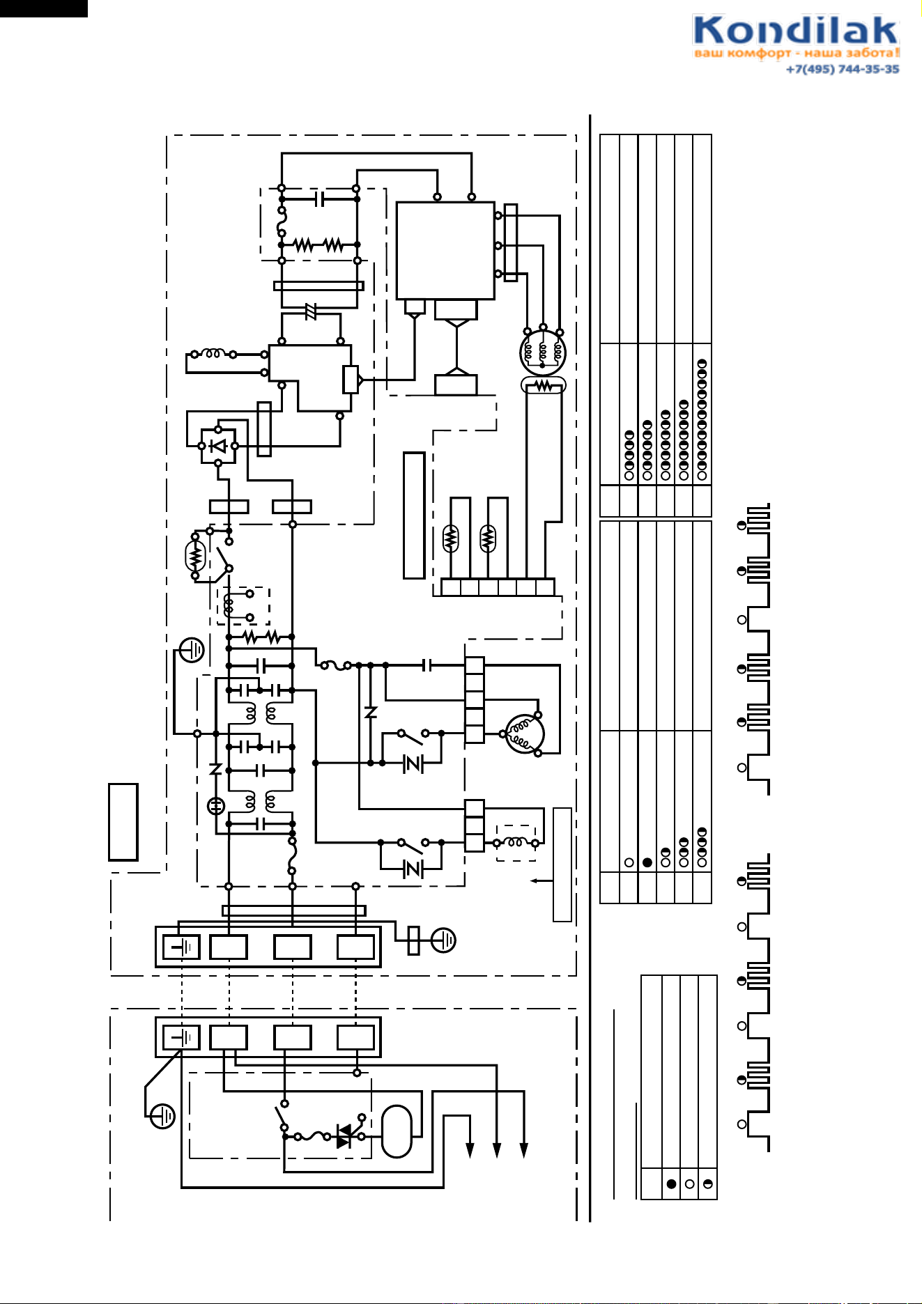
Figure W-5. Wiring Diagram for AU-X13BE and AE-X13BE
+
+
-
-
+
+-
-
+
+
-
-
N
1
2
INDOOR UNIT
TERMINAL
BOARD
CONTROL
BOARD
UNIT
POWER
SUPPLY
FAN
MOTOR
TERMINAL BOARD
UNIT TO UNIT CORD
SINGLE PHASE
220-240V 50Hz
BL
T2
BR
T3
RE
FC3
FC4
BULK HEAD
RE
T1
WPE1
C31
C1
C2
20A
250V
SA1
RY1
G(Y) T4
L1
CN11
CN14
CT1
The voltage is high at C8 (electronic capacitors) on outdoor unit.
For mentenance discharge at C8 to prevent electric shock.
In case that WPE2 has been fused, the voltage is kept high at C8.
CAUTION
BK
:
BLACK RE
:
RED YE
:
YELLOW
BL
:
BLUE WH
:
WHITE G:GREEN
BR
:
BROWN OR
:
ORANGE
GR
:
GRAY G
(
Y
):
GREEN-YELLOW
U
(
R
)
V
(
S
)
W
(
C
)
BL
GR
OR
FAN
MOTOR
BL
BL
PTC
MRY1
IN OUT
GR
T6
T5
BK
FC5
T9
T7
T8
YE
WH WH
RE
RE
RE
C8
OUTDOOR UNIT
POWER
TRANSISTOR
MODULE
(
QM1
)
UVW
RE
WH
BK
COMPRESSOR
THERMISTOR
PIPE TEMP.
THERMISTOR
OUTDOOR
TEMP.
THERMISTOR
COMPRESSOR TEMP.
CN8
FAN MOTOR
CAPACITOR
2µF 430V
TH2
TH1
TH3
RE
OR
G
3
1
3
1
5
LED INDICATION OF SELF-DIAGNOSIS
ON OUTDOOR UNIT
LED BLINKING
LED turns on
Slow flashing
(
1 time for 2 seconds
)
Quick flashing
(
3 times for 2 seconds
)
Example: NO.2 Compressor lock
on
off
1.0sec 0.6sec 1.0sec 0.6sec 1.0sec 0.6sec
NO.3 Overheat of the compressor
1.0sec 0.6sec 0.6sec 1.0sec 0.6sec 0.6sec
1
2
3
4
5
NO. LED indication pattern
Mulfunction part or abnormal condition
Normal
Compressor lock
Abnormal signal line
Overheat of the compressor
QM1(IPM) Abnormality
Short circuit of the thermistor
7
8
6
NO. LED indication pattern
Mulfunction part or abnormal condition
Open circuit of the thermistor
AC overcurrent
9
Power factor module error
AC abnormal current
BK
1
2
3
4
5
6
NR1
NR2
CNR1
RY2
CNR2
N
1
2
L3
L4
WPE3
3A
250V
CN3CN4
CONTROL BOARD UNIT
DIODE BRIDGE
DB1
BL
C5
WPE2
20A
250V
BL
BR
FC2
BL
YE
FC1
T10
C10
~~
C
AM
4 WAY
VALVE
except cooling only models
ACTIVE
FILTER
AF1
CN12
CN13
I
I
0
0
LL
14
CONTROL
BOX
C8: 1300µF 450V
12
AH-X08BE/10BE/13BE
AY-X08BE/10BE/13BE
AY-X08BE-C/10BE-C
AU-X08BE/10BE/13BE
AE-X08BE/10BE/13BE
AE-X08BE-C/10BE-C
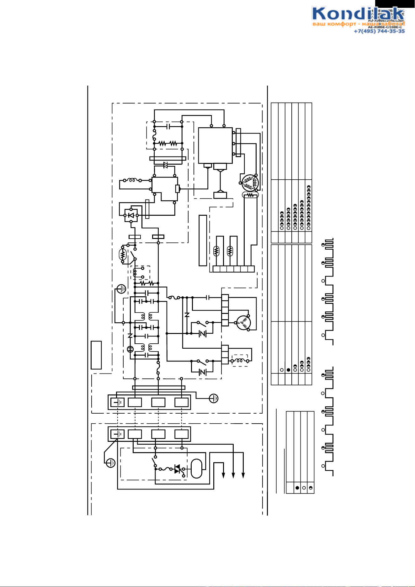
Figure W-6. Wiring Diagram for AU-X08BE/X10BE
+
+
-
-
+
+-
-
+
+
-
-
N
1
2
INDOOR UNIT
TERMINAL
BOARD
CONTROL
BOARD
UNIT
POWER
SUPPLY
FAN
MOTOR
TERMINAL BOARD
UNIT TO UNIT CORD
SINGLE PHASE
220-240V 50Hz
BL
T2
BR
T3
RE
FC3
FC4
BULK HEAD
RE
T1
WPE1
C1
C2
15A
250V
SA1
RY1
T4
G(Y)
L1
CN11
CT1
The voltage is high at C8 (electronic capacitors) on outdoor unit.
For mentenance discharge at C8 to prevent electric shock.
In case that WPE2 has been fused, the voltage is kept high at C8.
CAUTION
BK
:
BLACK RE
:
RED YE
:
YELLOW
BL
:
BLUE WH
:
WHITE G:GREEN
BR
:
BROWN OR
:
ORANGE
GR
:
GRAY G
(
Y
):
GREEN-YELLOW
U
(
S
)
V
(
R
)
W
(
C
)
BL
GR
OR
FAN
MOTOR
BL
BL
PTC
MRY1
IN OUT
GR
T6
T5
BK
FC6
FC7
FC5
T9
T7
T8
YE
WH WH
RERE
C8
OUTDOOR UNIT
POWER
TRANSISTOR
MODULE
(
QM1
)
UVW
RE
WH
BK
COMPRESSOR
THERMISTOR
PIPE TEMP.
THERMISTOR
OUTDOOR
TEMP.
THERMISTOR
COMPRESSOR TEMP.
CN8
TH2
TH1
TH3
RE
OR
G
3
1
5
LED INDICATION OF SELF-DIAGNOSIS
ON OUTDOOR UNIT
LED BLINKING
LED turns on
Slow flashing
(
1 time for 2 seconds
)
Quick flashing
(
3 times for 2 seconds
)
Example: NO.2 Compressor lock
on
off
1.0sec 0.6sec 1.0sec 0.6sec 1.0sec 0.6sec
NO.3 Overheat of the compressor
1.0sec 0.6sec 0.6sec 1.0sec 0.6sec 0.6sec
1
2
3
4
5
NO. LED indication pattern
Mulfunction part or abnormal condition
Normal
Compressor lock
Abnormal signal line
Overheat of the compressor
QM1(IPM) Abnormality
Short circuit of the thermistor
7
8
6
NO. LED indication pattern
Mulfunction part or abnormal condition
Open circuit of the thermistor
AC overcurrent
9
Power factor module error
AC abnormal current
BK
1
2
3
4
5
6
NR1
NR2
CNR1
N
1
2
L3
L4
WPE3
3A
250V
CN3
CONTROL BOARD UNIT
DIODE BRIDGE
DB1
BL
C5
WPE2
10A
250V
BL
BR
FC2
BL
YE
FC1
T10
C10
~~
C
AM
ACTIVE
FILTER
AF1
I
I
0
0
LL
CONTROL
BOX
FAN MOTOR
CAPACITOR
1.5
µ
F 430V
C8: 1000
µ
F 420V
C31
13
AH-X08BE/10BE/13BE
AY-X08BE/10BE/13BE
AY-X08BE-C/10BE-C
AU-X08BE/10BE/13BE
AE-X08BE/10BE/13BE
AE-X08BE-C/10BE-C
For Model AH-X08BE/X10BE/X13BE, AY-X08BE/X08BE-C/X10BE/X10BE-C/X13BE
DESCRIPTION MODEL REMARKS SITE
Indoor fan motor ML-A901 220 - 240V, 50Hz AH, AY
Indoor fan motor capacitor – 430V, 2µF AH, AY
Transformer – Primary; AC 220 - 240V, 50Hz AH, AY
Secondary; AC19V, 50Hz
WPE1 – QFS-GA027JBE0 (250V, 3A) AH, AY
or QFS-GA040JBZZ (250V, 3A)
For Model AE-X10BE/X10BE-C
Compressor HV237A1-S15DK 3-PHASE Induction motor AE-X10BE
Compressor HV187X1-S12F3 3-PHASE Induction motor
AE-X10BE-C
Outdoor fan motor ML-A902 220 - 240V, 50Hz 220V, 60Hz –
Outdoor fan motor capacitor – 430V, 1.5µF –
WPE1 – QFS-GA033JBZZ(250V, 15A) –
WPE2 – QFS-GA015JBE0(250V, 10A) –
WPE3 – QFS-GA027JBE0 (250V, 3A) –
or QFS-GA040JBZZ (250V, 3A)
For Model AE-X08BE/X08BE-C
Compressor HV166A1-S10DK 3-PHASE Induction motor AE-X08BE
Compressor 44A07QV2JD 3-PHASE Induction motor
AE-X08BE-C
Outdoor fan motor ML-A902 220 - 240V, 50Hz 220V, 60Hz –
Outdoor fan motor capacitor – 430V, 1.5µF –
WPE1 – QFS-GA033JBZZ(250V, 15A) –
WPE2 – QFS-GA015JBE0(250V, 10A) –
WPE3 – QFS-GA027JBE0 (250V, 3A) –
or QFS-GA040JBZZ (250V, 3A)
For Model AU-X08BE/X10BE
Compressor 2RV110N5EA04 3-PHASE Induction motor –
Outdoor fan motor ML-A902 220 - 240V, 50Hz 220V, 60Hz –
Outdoor fan motor capacitor – 430V, 1.5µF –
WPE1 – QFS-GA033JBZZ(250V, 15A) –
WPE2 – QFS-GA015JBE0(250V, 10A) –
WPE3 – QFS-GA027JBE0 (250V, 3A) –
or QFS-GA040JBZZ (250V, 3A)
For Model AU-X13BE/AE-X13BE
Compressor HV237A1-S15DK 3-PHASE Induction motor AU, AE
Outdoor fan motor ML-A903 220 - 240V, 50Hz 220V, 60Hz AU, AE
Outdoor fan motor capacitor – 430V, 2.0µF AU, AE
WPE1 – QFS-GA014JBE0(250V, 20A) AU, AE
WPE2 – QFS-GA019JBE0(250V, 20A) AU, AE
WPE3 – QFS-GA027JBE0 (250V, 3A) AU, AE
or QFS-GA040JBZZ (250V, 3A) AU
ELECTRICAL PARTS
14
AH-X08BE/10BE/13BE
AY-X08BE/10BE/13BE
AY-X08BE-C/10BE-C
AU-X08BE/10BE/13BE
AE-X08BE/10BE/13BE
AE-X08BE-C/10BE-C
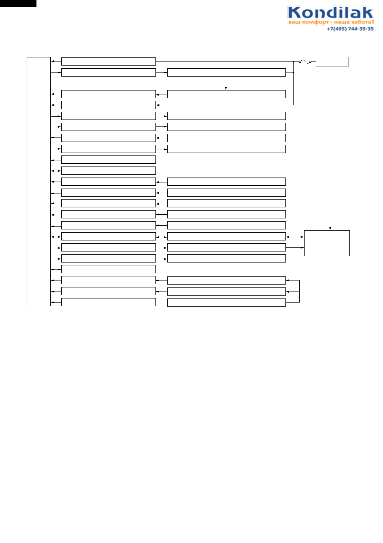
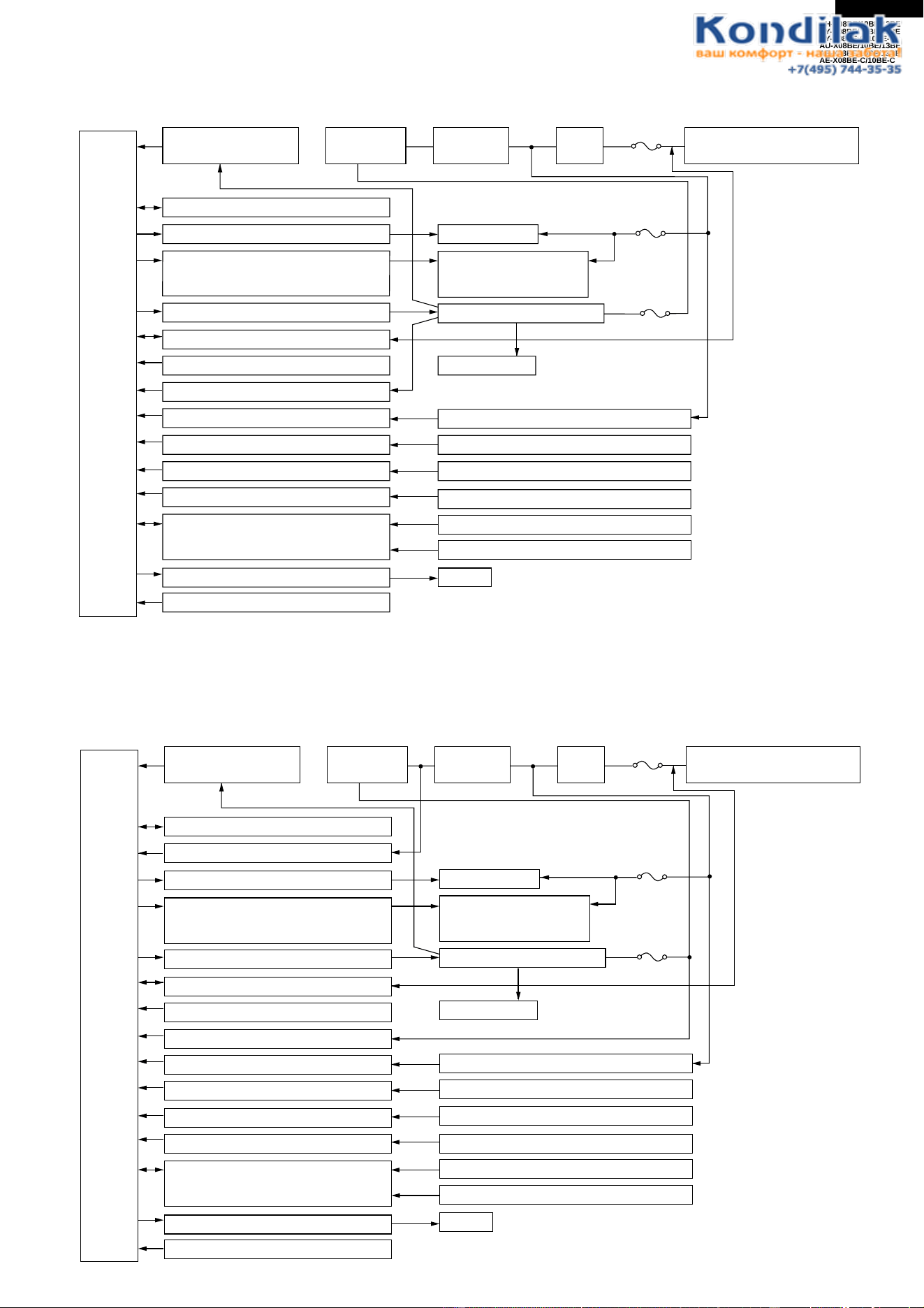
BLOCK DIAGRAMS
INDOOR UNIT
AC power
CPU
3 A
WPE1
DC power supply circuit
Fan motor phase control circuit
Rotation pulse input circuit
AC clock circuit
Louvre motor drive circuit(upper)
Louvre motor drive circuit(lower)
Remote controller signal reception circuit
Buzzer drive circuit
CPU reset circuit
CPU oscillator circuit
Room temp. detect circuit
Heat exchanger pipe thermo circuit
Compensation circuit/ select circuit
Compensation circuit
Switchover circuit
Serial I/O circuit
Compressor relay drive circuit
LED drive circuit
Auto restart circuit
Test run circuit
Auxiliary mode
Power on circuit
Room fan motor
Fan motor pulse detect
Flow direction control (louver motor upper)
Flow direction control (louver motor lower)
Wireless remote control operation
Audible operation confirmation
Room temp. thermistor
Heat exchanger pipe thermistor
Blower temperature, fan speed, model select
Outdoor ratings
Wireless, preheat
Indoor/outdoor control signal I/O
Outdoor unit power supply on/off control
LED display
Test run (forced operation)
Auxiliary mode button ON/OFF
Self diagnostics, fault diagnosis
Unit-unit wiring
(AC power and
serial signals)
15
AH-X08BE/10BE/13BE
AY-X08BE/10BE/13BE
AY-X08BE-C/10BE-C
AU-X08BE/10BE/13BE
AE-X08BE/10BE/13BE
AE-X08BE-C/10BE-C
CPU
15 A
protection
Outdoor fan
4-way valve(except for
the AU-X08BE/X10BE)
Power transistor module
Compressor
Current transformer
Compressor thermistor
Heat exchanger pipe thermistor
Outdoor temperature thermistor
Heat exchanger pipe thermistor(option)
Outdoor temperature thermistor(option)
LED
3 A
protection
10 A
protection
Power supply circuit
(built into IPM)
CPU oscillator circuit
Outdoor fan relay drive circuit
4-way valve relay drive circuit
(except for the AU-X08BE/X10BE)
Power transistor module drive circuit
Serial I/O circuit
CPU reset circuit
DC overcurrent detection circuit
AC overcurrent detection circuit
Compressor thermo circuit
Heat exchanger pipe thermo circuit
Outdoor temp. thermo. circuit
Winter kit circuit (option)
LED drive circuit
Test mode circuit
Active filter
circuit
Filter
circuit
Smoothing
circuit
Unit-unit wiring (AC power
and serial signals)
CPU
20 A
protection
Outdoor fan
4-way valve(except for
the AU-X13BE)
Power transistor module
Compressor
Current transformer
Compressor thermistor
Heat exchanger pipe thermistor
Outdoor temperature thermistor
Heat exchanger pipe thermistor(option)
Outdoor temperature thermistor(option)
LED
3 A
protection
20 A
protection
Power supply circuit
(built into IPM)
CPU oscillator circuit
DC overvoltage detection circuit
Outdoor fan relay drive circuit
4-way valve relay drive circuit
(except for the AU-X13BE)
Power transistor module drive circuit
Serial I/O circuit
CPU reset circuit
DC overcurrent detection circuit
AC overcurrent detection circuit
Compressor thermo circuit
Heat exchanger pipe thermo circuit
Outdoor temp. thermo. circuit
Winter kit circuit (option)
LED drive circuit
Test mode circuit
Active filter
circuit
Filter
circuit
Smoothing
circuit
Unit-unit wiring (AC power
and serial signals)
OUTDOOR UNIT for AU-X08BE/X10BE and AE-X08BE/X08BE-C/X10BE/X10BE-C
OUTDOOR UNIT for AU-X13BE and AE-X13BE
16
AH-X08BE/10BE/13BE
AY-X08BE/10BE/13BE
AY-X08BE-C/10BE-C
AU-X08BE/10BE/13BE
AE-X08BE/10BE/13BE
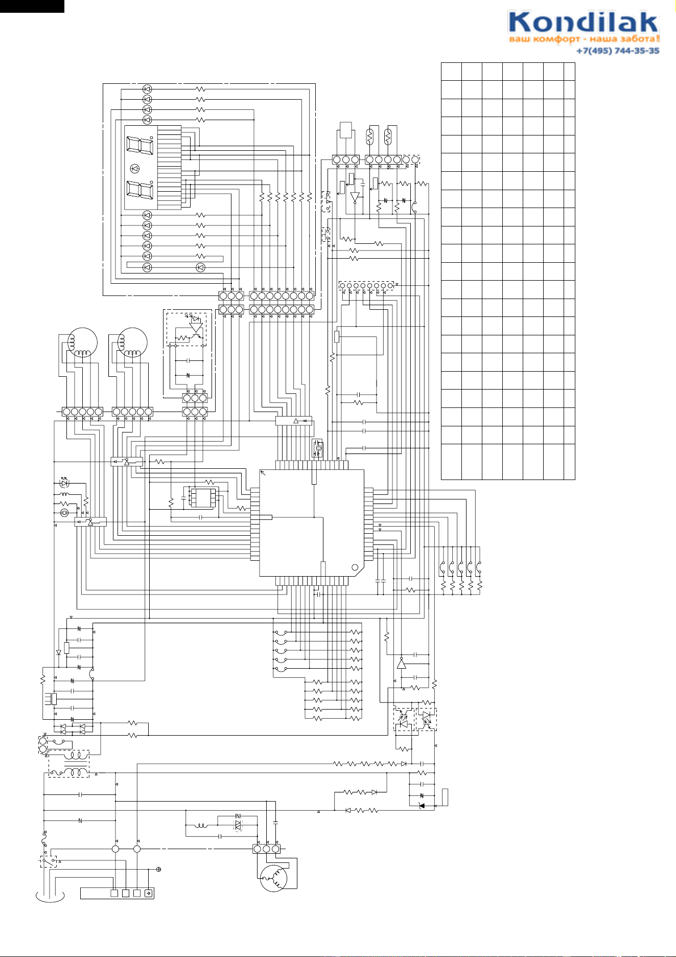
AE-X08BE-C/10BE-C
MICROCOMPUTER CONTROL SYSTEM
Figure L-1. Electronic Control Circuit Diagram for AH-X08BE/X10BE/X13BE and AY-X08BE/X08BE-C/X10BE/X10BE-C/X13BE
(CN9)
LED101
LED104
LED103
LED102
LED110
LED109
LED108
LED107
LED106
LED105
R101
R102
R103
R104
R105
R106
R107
R108
R109
1/2W
1/2W
1/2W
1/2W
220
220
300
220
220
220
220
220
100
1/2W
1/2W
1/2W
1/2W
1/2W
LED111
1/2W
1/2W
1/2W
330
R114
R40
3.3K
50V
50V
C21
C22 1000p
1000p
BCN3
BCN2
R58~R62
(SW2)
MOTOR
FAN
IC
HOLE
3
2
1
P00
P01
P02
P03
P04
P05
P06
P07
P10
P11
P12
P13
P14
P16
P17 33
34
35
36
37
38
39
40
41
42
43
44
45
46
47
48
52
53
54
55
56
57
58
59
60
61
62
63
64 P63
P64
P65
P66
P67
AVss
Vref
Vcc
P30
P31
P32
P33
P34
51
50
49
P35
P36
P20
P21
P22
32
31
30
P23
P24
P25
P26
P27
Vss
Xout
Xin
P40
P41
RESET
CNVss(Vpp)
P42
29
28
27
26
25
24
23
22
21
20
19
18
17
P62
P61
P60
P57
P56
P55
P54
P53
P52
P51
P50
P45
P43
1
2
3
4
5
6
7
8
9
10
11
12
13
14
15
16
NC
M3803**
IC1
(PATTERN SIDE)
PC2
PC1
4
2
4
3
1
2
4.7K
100K
+
0.047µ
50V
250V
0.01µ
680 680
2W 2W
680 680
2W 2W
680
2W
22K
P15
1
10K
10K
0.1µ
25V
8M
6
5
4
3
2
1
PIPE TEMP.
TH2
10kΩ(25˚C)
15kΩ(25˚C)
ROOM TEMP.
TH1
C2
0.22µ
250V
NR1
IN
T
250V
OUT
RY1
WPE
N
N
2S
1
NIT
UTDOOR
O
TERMINAL
BOARD
KID65783AP
IC6
10
SW1
5V
GND
12V
-24V
33K
33K
33K
33K
33K
16V
C26
0.01µ
R41
1.8K
33K
33K
33K
1000P
3
2
3
1
2
R23
3.3K
CN6
100µ
C810V
+
FAN L
FAN M
FAN H
RATE HEAT
TEA
MODEL 5
MODEL 4
MODEL 3
MODEL 2
MADEL 1
R42
R43
R44
R45
R46
R47
R48
R49
R50
R51
R52
R53
R54
R55
R56
JP 1
JP 2
JP 3
JP 4
JP 5
R67 R66
12K 12K
2W
D9
D8
R65R64
11K
2W 2W
11K
2W
C30
100µ
35V
C29
ZD1
R63
C28
D7
R57
C27
R38
R37
R36
R35
R34
JP8
JP7
JP6
R30
380
R29
680
C19
+
+
C18
10µ
16V16V
10µ
10K
(F)
R27
10K
(F)
R26
R21
R20
R19
C13
C12
C11
IC7
IC8
OSC1
FRONT
1/2W
R9
R8
C9
C10
1000p
50V
25V
0.1µ
R5
RY1
R4
BZ1
BUSY
1
12V
2
5V
3
4
CLOCK
5
SERIAL
OE
6
7
RESET
GND
8
HOT KEEP
PREHEAT
WIRELESS
2.7K
50V
1000p
1000p
50V
P37
P44
P46
P47
4
3
2
1
7
6
5
8
1
1K
FUSE
THERMAL
SSR1
470
1.8K
16
9
10K
3
1
OWER
UPPLY
INGLE
HASE
21
JP10
33KR2
TRANS1
D1~4
33K
R3
+
C450V
0.1µ
7812
IC2
35V C3
1000µ
IN
0.1µ
25V
OUT
C5
+
47µ
25V
100 1/2W
R1
JP11
+
C6
25V
47µ
0.1µ
25V C7
IN
IC3
D5
7805
25V
0.1µ
R31
IC4
8
NC
9
118
13
11
C31
250V
0.01µ
SSR1
CNR1
L1
430V
C1
2µ
FUSE
THERMAL
MOTOR
FAN
5
3
1
CN1
C32
C33
680
R6
CN101
22
33
11
88
11
22
33
44
55
66
77
CN102
NC
NC
10(B2)
11(A2)
12(F2)
15(B1)
18(F1)
17(G1)
16(A1)
14(CM1)
13(CM2)
9(H2)
8(C2)
7(G2)
6(D2)
5(E2)
4(H1)
3(C1)
2(D1)
1(E1)
H2
H1
CM1,2
D2
G2
A2
E2
F2
B2
C2
D1
G1
A1
C1
B1
E1
F1
33K
33K
R33
R32
JP9
JP99
TEST
POWE ON
R39
20K
C24 16V
0.01µ
1
3
2
C2550V
1000P
330
W115
1/2W
LED121
R1163301/2W
1/2W
R111
330
R112
R110
330
330
1/2W R113330
25V
0.1µ
680
680
Q1
Q2
R68
R69
3A
33K
CN7
0.1µ
25V
33µ
10V
+
5V
GND
C201
C202
IC201
BCN201
BCN1
11
33
22
6.8K
8
IC59
1
16
10K
R7
CN3
1
2
3
4
5
LOUVER
MOTOR
UPPER
LOWER
LOUVER
MOTOR
4
5
1
CN2
2
3
∆ :TEST POINT
(NOTE)
LED101 : OPERATION
LED102 : TIMER
LED103 : ROOM TEMP.
LED104 : OUTDOOR TEMP.
SW1 : AUX.(TEST RUN)
SW2 : POWER SELECTION
LED105 : POWER MONITOR ECO
LED106 : POWER MONITOR 1
LED107 : POWER MONITOR 2
LED108 : POWER MONITOR 3
LED109 : POWER MONITOR 4
LED110 : POWER MONITOR POWER
H
L
50V
C34
JP34
C1716V
0.01µ
JP23680
USENONE
SW2
USE
NONE
NONENONE NONENONEUSE
15K13K13K 15K15K13K13K15K13K
NONE NONE USENONE NONE NONENONE
USEUSENONE NONENONENONE USENONENONE
13K 15K 13K 13K 15K 15K13K 13K 15K
USE NONE NONE
NONENONEUSEUSE
15K13K13K 15K15K13K13K15K13K
NONE NONE USENONE NONE NONENONE NONE
NONENONENONE NONENONENONE USEUSENONENONENONE
13K 24K 15K13K 13K 15K 15K13K 13K 130K
AH-X08BE
AH-X13BE
AH-X10BE
AY-X08BE
AY-X13BE
AY-X10BE
MODEL
JP1 JP2 JP3 JP4 JP5 JP6 JP7 JP8 JP9 R51R50R49R48R47R46R45R44R43R42JP99
15K13K13K 15K15K13K13K 15K15K13K
NONEUSE NONE NONE NONE USE USENONE NONE NONE
15K13K13K 15K15K13K13K 15K15K13K
NONE NONE NONE USE USENONE NONE NONE
17
AH-X08BE/10BE/13BE
AY-X08BE/10BE/13BE
AY-X08BE-C/10BE-C
AU-X08BE/10BE/13BE
AE-X08BE/10BE/13BE
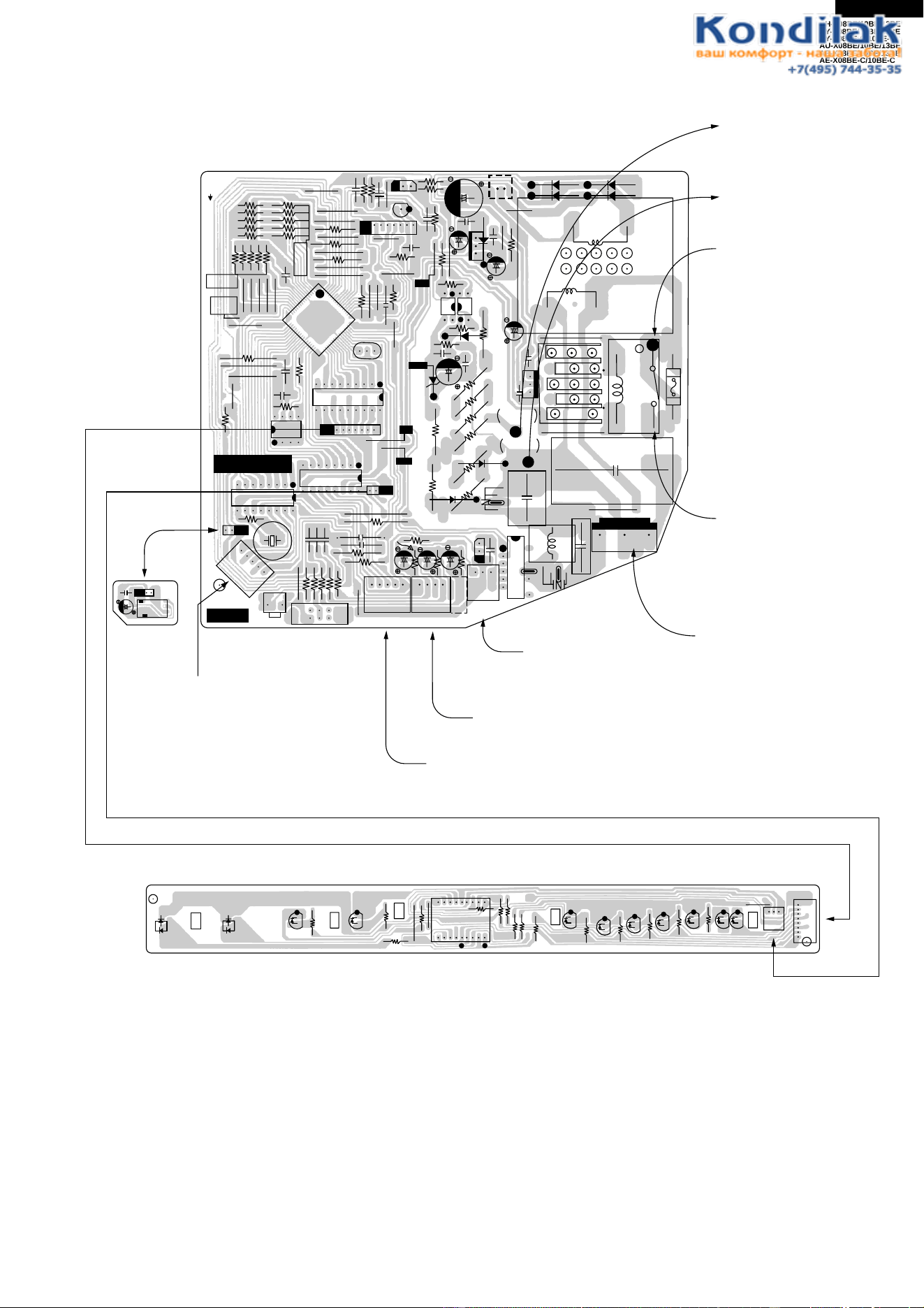
AE-X08BE-C/10BE-C
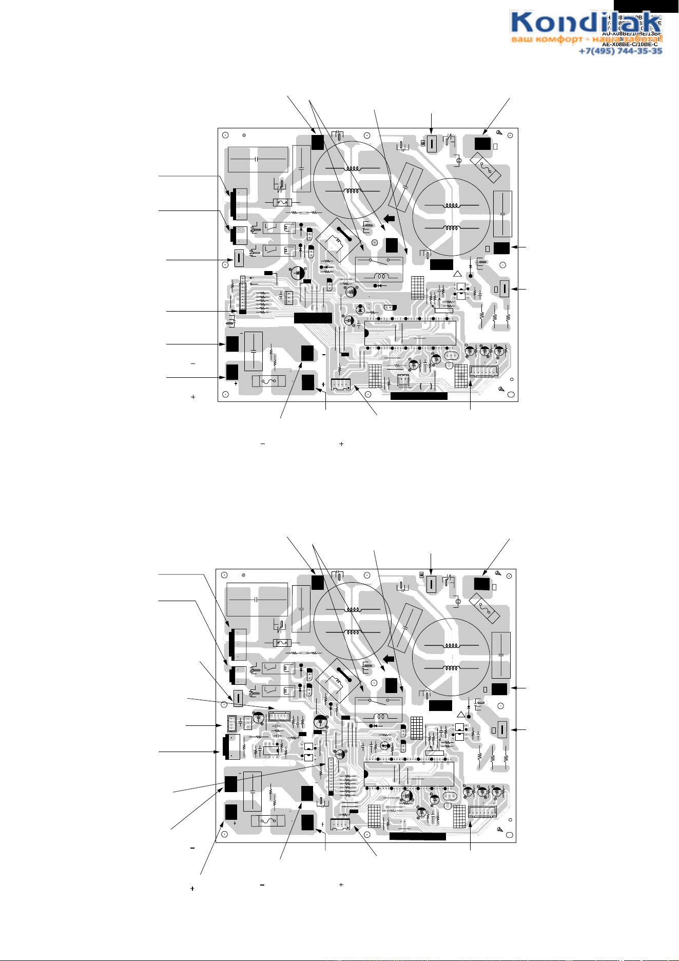
Figure L-2 Printed Wiring Board for AH-X08BE/X10BE/X13BE and AY-X08BE/X08BE-C/X10BE/X10BE-C/X13BE
QPWBFB389JBZZ
HEAT
COOL
RATE
FAN H
FAN M
FAN L
R43
R51
R47
R49
R45
1
JP1
R53
R54
R55
R56
C27
JP2
JP24
R6
JP22
JP21
C9
R8
JP20
C10
R9
R7
JP3
JP4
JP5
2345
MODEL
SELECT
1
18
16
BZ1
R4
BCN1
CN2
9
1
1
5
SW1
SW2
3
4IC8
IC4
58
DPWBF
JB
R69
R68
C11
C12
R5
JP17
BCN2
31
R20
R30
C21
C22
C23
R31
R20
R19
LOUVER LOW
JP16
JP15
H
L
LOUVER UP
CN3
THERMISTOR
CN7
1
51 4
1
19
10
18
18
IC5
BCN3
JP18
JP19
IC6
OSC1
8
916
IC1
1
16
33
32
17
48
49
49
JP24
JP6
JP7
JP8
JP31
JP33
R35
R36
R34
JP27
R42
R44
R46
R48
R50
C26
R41
R40
C25
JP32
C7
R39
R37
C24
JP29
R31
PC2
PC1
JP23
C17
C29
C3
R58
C32
C2
NR1
R65
R64
C34
Q2
32 1
R28
C20
R27
C19
R26
C18
JP34
2
8
9
15
C31
RY1
IC3
WPE1 3A 250V
BLACK
C4
C30
ZD1
JP99
R32
JP9
C8
JP28
D5
IC3
C6
R1
JP11
TRANS1
Q1
R3
R2
C3
(CN8)
1
12 3
3
8
IC7
C33
JP10
CN9
JP30
C13
R21
JP25
R38
2
3
3
D7
R63
C28
R57
3
4
1
2
JP14
TERMINAL
BOARD
TERMINAL
BOARD
JP13
BROWN
IN
OUT
S
RED
N
BLUE
L1
SSR1
1
CN1
FAN M
5
JP12
CNR1
FAN M
CN6
R23
R66
R67
R62
R61
R60
R59
D9
D8
1
D2
D4
D1
D3
C1
3
L
GND
+12V
-24V
+5V
BCN201
C202
C201
1
3
IC201
FP389-DISPLAY
JP101
CN102
81
LED111
LED110
LED109
LED108
LED107
LED106
LED105
R109
R108
R107
R106
R105
R111
R113
R112
R110
R116
R115
JP102
JP103
R102
LED104
R103
LED103
R101
CN101
13
R114
1018
9
1
LED121
R101
LED102
LED101
TO TERMINAL " 2 " OF
TERMINAL BOARD 4P
(RED)
TO TERMINAL " N " OF
TERMINAL BOARD 4P
(BLUE)
FROM
TERMINAL " 1 " OF
TERMINAL BOARD 3P
(BROWN)
FROM
TERMINAL " 1 " OF
TERMINAL BOARD 4P
(BLACK)
FROM
FAN
MOTOR
FROM
FAN
MOTOR
FROM
THERMISTOR
FROM
LOUVER MOTOR UPPER
(TOP)
FROM
LOUVER MOTOR LOWER
(BOTTOM)
18
AH-X08BE/10BE/13BE
AY-X08BE/10BE/13BE
AY-X08BE-C/10BE-C
AU-X08BE/10BE/13BE
AE-X08BE/10BE/13BE
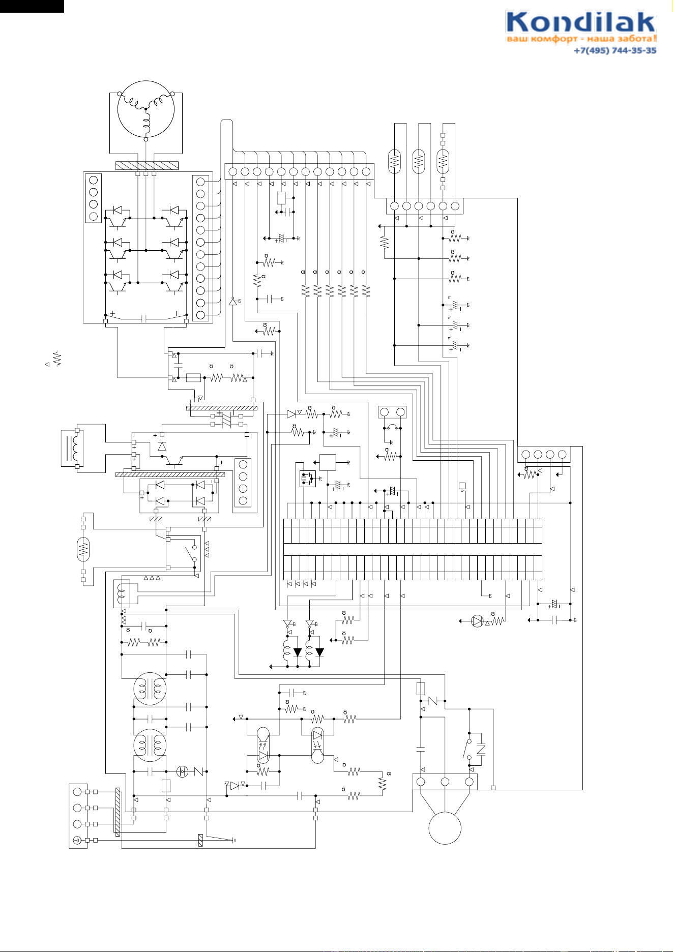
AE-X08BE-C/10BE-C
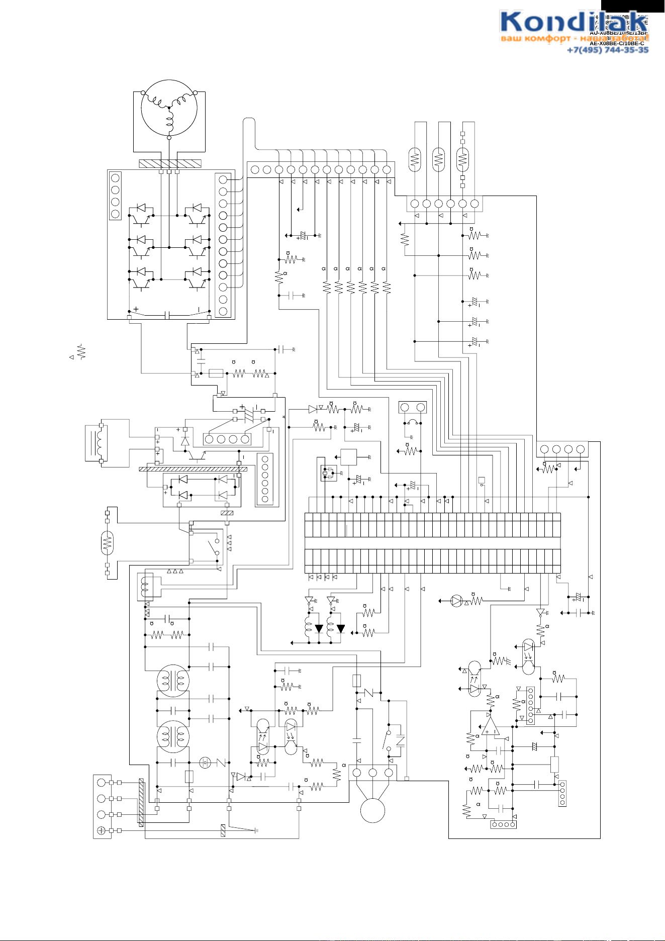
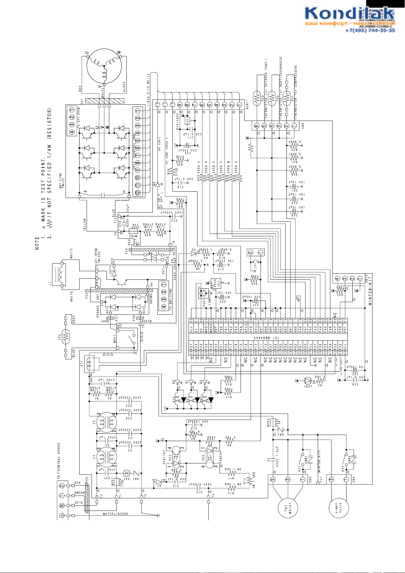
Figure L-3. Electronic Control Circuit Diagram for AU-X08BE/X10BE
TB (TERMINAL BOAOD)
N12
1
2
3
4
BLUE
BROWN
RED
FC4
FC3
GREEN/YELLOW
T2
T1
T4
T3
L3 L4
C31
275V 1µF
C4
250V 2200pF
1
2
3
4
C2
275V 1µF
C3
250V 2200pF
C34
250V 2200pF
WPE1
250V
15A
C1
275V 1µF
C33
250V 2200pF
R2 R1
1/4W
510K
1/4W
510K
CT1
TO QM1 (IPM)
T5
T6
MRY1
PTC
BLU
GRAY
GRAY
WHITE
WHITE
L1
IN
IN
LL
ORANGE
AC1
FC2
FC5
FC7
FC6
AC2
BLACK
BROWN
4321
OUT
OUT
AF1 (PFM)
TM-05C
RED
RED
BLUE
BLUE
C8
420V 1000µF
C30
25V 100µF
C11
25V 0.1µF
C18
50V 0.1µF
R35
510
R41
10K
R36
510
BLU
NOTE
1. MARK IS TEST POINT.
2. IF NOT SPECIFIED 1/4W (RESISTOR)
YELLOW
T9
T10
T7
C10
630V 0.33µF
R39
1/2W
270K
250V
10A
WPE2
13V
5V
5V
R40
1/2W
270K
T8
C32
250V 2200pF
1 : Red 2-12 : White
12
11
10
9
8
7
6
5
4
3
2
1
12 11 10
987654321
CN11 (CONTROL PWB)
U
V
W
4321
QM1 (IPM)
TM-32
TO AF1 (PFM)
FC1
RED
WHITE
BLACK
U
V
W
IC2
Q4
AF ON H
AF OFF L
(AF CONT)
(AF ARM) ERROR H
R33
R32
R31
R30
R29
R28
390 U
390 X
390 V
390 Y
390 W
390 Z
6
5
4
3
2
1
BCN11
CN8
TH3
(THERMISTOR for OUTDOOR TEMP.)
TH2
(THERMISTOR for HEAT-EXCHANGER)
TH1
(THERMISTOR for COMPRESSOR)
R38
6.8K F
C26
16V 10 F
5V
C22
16V 10 F
C21
16V 10 F
R21
6.8K F
R20
6.8K F
C15
10V 220µF
R10
6.8K F
R8
2.70K F
R9
1.00K F
D2
1
2
3
1
2
3
5V
C23
50V 1µF
PST
993D
IC3
OSC1
10MHz
5V
5V
C17
10V 100µF
2
1
F
R46
10K
JP1
R34
10K
5V
NC
WINTER-KIT
4
3
2
1
CN10
5V
33
34
35
36
37
38
39
40
41
42
43
44
45
46
47
48
49
50
51
52
53
54
55
56
57
58
59
60
61
62
63
64
32
31
30
29
28
27
26
25
24
23
22
21
20
19
18
17
16
15
14
13
12
11
10
09
08
07
06
05
04
03
02
01
P27
P26
P25
P24
P23
P22
P21
P20
P17
P16
P15
P14
P13
P12
P11
P10
P07
P06
P05
P04
P03
P02
P01
P00
V
SS
P37
P36
P35
P34
P33
P32
V
CC
V
SS
XI
X0
MOD1
MOD2
RST
P60
P61
P62
P63
P64
AV
SS
AVR
AV
CC
AN7
AN6
AN5
AN4
AN3
AN2
AN1
AN0
P40
P41
P42
P43
P44
P45
P46
P47
P30
P31
NC
NC
NC
NC
NC
NC
NC
NC
NC
NC
NC
NC
NC
NC
NC
NC
NC
IC1 MB89855
C16
25V 0.1µF
C20
10V 100µF
5V
(AF CONT)
(AF ARM) ERROR H
R3
2.2K
5V
LED1
C5
430V 1.5µF
WPE3
250V
3A
NR2
Fan
Motor
5
3
1
CN3
T11
RY1
CNR1
(WINTER KIT)
C12
250V 4700pF
C14
50V 1000pF
C13
25V 0.01µF
R4
D1
3.3K
R6
2.7K
R5
5.6K
R7
4.7K
PC817X7
PC1
PC2
PC853H
1
23
4
1
23
4
5V
R11
2W 1.0K
R12
2W 1.0K
R13
2W 1.0K
R17
10K
R16
10K
13V
RY1
D6
Q1
MRY1
D8
Q3
5V
NR1
SA1
19
AH-X08BE/10BE/13BE
AY-X08BE/10BE/13BE
AY-X08BE-C/10BE-C
AU-X08BE/10BE/13BE
AE-X08BE/10BE/13BE
AE-X08BE-C/10BE-C
Figure L-4. Electronic Control Circuit Diagram for AU-X13BE
TB (TERMINAL BOAOD)
N12
1
2
3
4
BLUE
BROWN
RED
FC4
FC3
GREEN/YELLOW
T2
T1
T4
T3
L3 L4
C31
275V 1µF
C4
250V 2200pF
C12
250V 4700pF
C14
50V 1000pF
C1
275V 1µF
C13
25V 0.01µF
C5
430V 2µF
C46
25V 100µF
C45
25V 0.1µF
C41
25V 0.1µF
C43
25V 0.1µF
C16
25V 0.1µF
1
2
3
4
C2
275V 1µF
C3
250V 2200pF
C34
C33
250V 2200pF
250V 2200pF
WPE1
250V
20A
WPE3
250V
3A
NR1
NR2
SA1
R2 R1
1/4W
510K
1/4W
510K
R4
D1
3.3K
R6
2.7K
R5
5.6K
R7
4.7K
PC817X7
PC1
PC2
PC853H
1
23
4
PC4
PC817X
PC3
PC817X
1
23
4
1
2
3
4
1
23
1
2
3
1
2
3
4
1
23
4
5V
R11
2W 1.0K
R17
10K
R16
10K
R60
10K
R58
10K
R34
10K
R12
2W 1.0K
R13
2W 1.0K
Fan
Motor
5
3
1
CN3
T11
RY1
CNR1
(WINTER KIT)
13V
RY1
D6
Q1
MRY1
D8
Q3
5V
C40
50V 0.01µF
C44
50V 0.01µF
1
2
3
4
R51
1/ 2W
270K
R50
1/2W
270K
R53
34.8K F
R54
15.8K F
R52
6.8K F
R56
3.3K
R59
390
R57
560 F
R3
2.2K
R55
1M
IC4
IC2
18V
18V
18V
18V
5V
18V 5V
5V
5V
5V
5V
5V
LED1
FROM C8
(CN12)
TO IPM (CN14)
1234
123456
TO PFM
(CN13)
8
1
2
3
C20
10V 100µF
C17
10V 100µF
C15
10V 220µF
C30
25V 100µF
C18
50V 0.1µF
C23
50V 1µF
5V
Q4
AF ON H
AF OFF L
(AF CONT)
(AF ARM) ERROR H
33
34
35
36
37
38
39
40
41
42
43
44
45
46
47
48
49
50
51
52
53
54
55
56
57
58
59
60
61
62
63
64
32
31
30
29
28
27
26
25
24
23
22
21
20
19
18
17
16
15
14
13
12
11
10
09
08
07
06
05
04
03
02
01
P27
P26
P25
P24
P23
P22
P21
P20
P17
P16
P15
P14
P13
P12
P11
P10
P07
P06
P05
P04
P03
P02
P01
P00
V
SS
P37
P36
P35
P34
P33
P32
V
CC
VSS
XI
X0
MOD1
MOD2
RST
P60
P61
P62
P63
P64
AV
SS
AVR
AV
CC
AN7
AN6
AN5
AN4
AN3
AN2
AN1
AN0
P40
P41
P42
P43
P44
P45
P46
P47
P30
P31
NC
NC
NC
NC
NC
NC
NC
NC
NC
NC
NC
NC
NC
NC
NC
NC
NC
IC1 MB89855
NC
WINTER-KIT
4
3
2
1
2
1
CN10
5V
F
R46
10K
R10
6.8K F
R38
6.8K F
R35
510
R36
510
R8
2.70K F
R9
1.00K F
JP1
PST
993D
IC3
OSC1
10MHz
654321
4321
12 11
FROM PWB (CN13)
T5
T6
MRY1
CT1
PTC
BLU
BLU
BLU
GRAY
GRAY
WHITE WHITE
L1
IN
IN
LL
ORANGE
AC1
FC2
FC5
AC2
BLACK
BROWN
1
2
3
4
OUT
OUT
AF1 (PFM)
SACT32010C
RED
RED
RED
NOTE
1. MARK IS TEST POINT.
2. IF NOT SPECIFIED 1/4W (RESISTOR)
YELLOW
QM1 (IPM)
TM-38
T9
T10
T7
T8
(CN12)
TO PWB
BLUE
BLUE
C8
450V 1300 F
C10
630V 0.33µF
C32
250V 2200pF
R39
1/2W
270K
250V
20A
WPE2
10
987654321
FROM PWB (CN14)
FC1
RED
WHITE
BLACK
1 : Red 2-10 : White
U
V
W
U
V
W
D2
R33
R32
R31
R30
R29
R28
430 U
430 X
430 V
430 Y
430 W
430 Z
C26
16V 10µF
12
11
10
9
8
7
6
5
4
3
2
1
6
5
4
3
2
1
13V
5V
5V
C22
16V 10µF
C21
16V 10µF
R21
6.8K F
R20
6.8K F
BCN11
CN8
TH3
(THERMISTOR for OUTDOOR TEMP.)
TH2
(THERMISTOR for HEAT-EXCHANGER)
TH1
(THERMISTOR for COMPRESSOR)
R40
1/2W
270K
CN11 (CONTROL PWB)
20
AH-X08BE/10BE/13BE
AY-X08BE/10BE/13BE
AY-X08BE-C/10BE-C
AU-X08BE/10BE/13BE
AE-X08BE/10BE/13BE
AE-X08BE-C/10BE-C
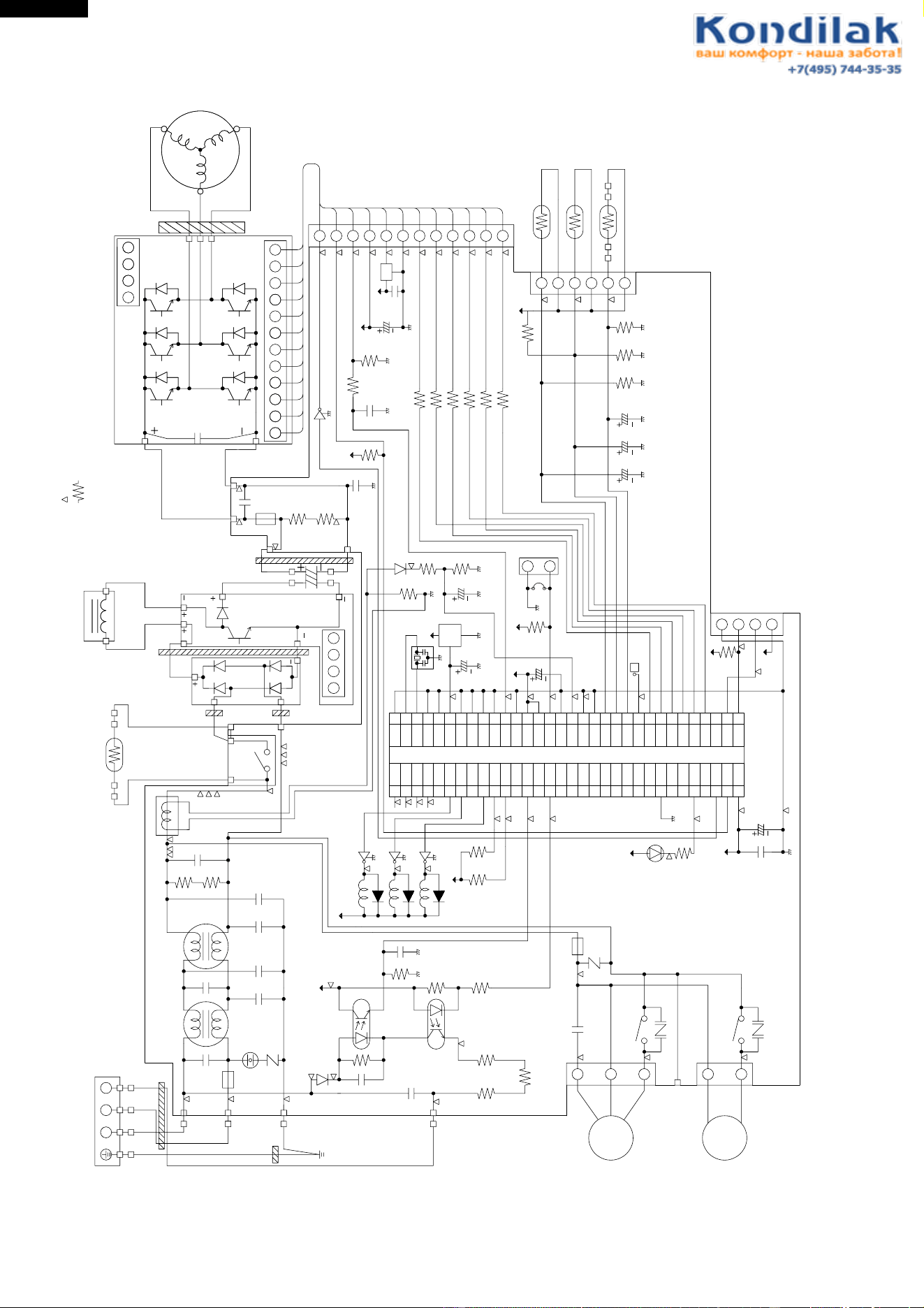
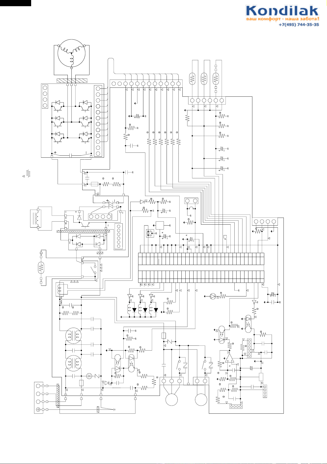
Figure L-5. Electronic Control Circuit Diagram for AE-X08BE/X10BE
TB (TERMINAL BOAOD)
N12
1
2
3
4
BLUE
BROWN
RED
FC4
FC3
GREEN/YELLOW
T2
T1
T4
T3
L3 L4
C31
275V 1µF
C4
250V 2200pF
1
2
3
4
C2
275V 1µF
C3
250V 2200pF
C34
250V 2200pF
WPE1
250V
15A
C1
275V 1µF
C33
250V 2200pF
R2 R1
1/4W
510KΩ
1/4W
510KΩ
CT1
TO QM1 (IPM)
T5
T6
MRY1
PTC
BLU
GRAY
GRAY
WHITE WHITE
L1
IN
IN
LL
ORANGE
AC1
FC2
FC5
FC7
FC6
AC2
BLACK
BROWN
4321
OUT
OUT
AF1 (PFM)
TM-05C
RED
RED
BLUE
BLUE
C8
420V 1200µF
C30
25V 100µF
C11
25V 0.1µF
C18
50V 0.1µF
R35
510Ω
R41
10KΩ
R36
510Ω
BLU
NOTE
1. MARK IS TEST POINT.
2. IF NOT SPECIFIED 1/4W (RESISTOR)
YELLOW
T9
T10
T7
C10
630V 0.33µF
R39
1/2W
270KΩ
250V
10A
WPE2
13V
5V
5V
R40
1/2W
270KΩ
T8
C32
250V 2200pF
1 : Red 2-12 : White
12
11
10
9
8
7
6
5
4
3
2
1
12 11 10 9 8 7 6 5 4 3 2 1
CN11 (CONTROL PWB)
U
V
W
4321
QM1 (IPM)
TM-32
TO AF1 (PFM)
FC1
RED
WHITE
BLACK
U
V
W
IC2
Q4
AF ON H
AF OFF L
(AF CONT)
(AF ARM) ERROR H
R33
R32
R31
R30
R29
R28
390Ω U
390Ω X
390Ω V
390Ω Y
390Ω W
390Ω Z
6
5
4
3
2
1
BCN11
CN8
TH3
(THERMISTOR for OUTDOOR TEMP.)
TH2
(THERMISTOR for HEAT-EXCHANGER)
TH1
(THERMISTOR for COMPRESSOR)
R38
6.8KΩF
C26
16V 10µF
5V
C22
16V 10µF
C21
16V 10µF
R21
6.8KΩF
R20
6.8KΩF
C15
10V 220µF
R10
6.8KΩF
R8
2.70KΩF
R9
1.00KΩF
D2
1
2
3
1
2
3
5V
C23
50V 1µF
PST
993D
IC3
OSC1
10MHz
5V
5V
C17
10V 100µF
2
1
F
R46
10KΩ
JP1
R34
10KΩ
5V
NC
WINTER-KIT
4
3
2
1
CN10
5V
33
34
35
36
37
38
39
40
41
42
43
44
45
46
47
48
49
50
51
52
53
54
55
56
57
58
59
60
61
62
63
64
32
31
30
29
28
27
26
25
24
23
22
21
20
19
18
17
16
15
14
13
12
11
10
09
08
07
06
05
04
03
02
01
P27
P26
P25
P24
P23
P22
P21
P20
P17
P16
P15
P14
P13
P12
P11
P10
P07
P06
P05
P04
P03
P02
P01
P00
V
SS
P37
P36
P35
P34
P33
P32
V
CC
V
SS
XI
X0
MOD1
MOD2
RST
P60
P61
P62
P63
P64
AV
SS
AVR
AV
CC
AN7
AN6
AN5
AN4
AN3
AN2
AN1
AN0
P40
P41
P42
P43
P44
P45
P46
P47
P30
P31
NC
NC
NC
NC
NC
NC
NC
NC
NC
NC
NC
NC
NC
NC
NC
NC
IC1 MB89855
C16
25V 0.1µF
C20
10V 100µF
5V
(AF CONT)
(AF ARM) ERROR H
R3
2.2KΩ
5V
LED1
C5
430V 1.5µF
WPE3
250V
3A
NR2
Fan
Motor
4-WAY
Valve
5
3
1
3
1
CN3
T11
CN4
RY1
CNR1
RY2
CNR2
(WINTER KIT)
C12
250V 4700pF
C14
50V 1000pF
C13
25V 0.01µF
R4
D1
3.3KΩ
R6
2.7KΩ
R5
5.6KΩ
R7
4.7KΩ
PC817X7
PC1
PC2
PC853H
1
23
4
1
23
4
5V
R11
2W 1.0KΩ
R12
2W 1.0KΩ
R13
2W 1.0KΩ
R17
10KΩ
R16
10KΩ
13V
RY2
D7
Q2
RY1
D6
Q1
MRY1
D8
Q3
5V
NR1
SA1
21
AH-X08BE/10BE/13BE
AY-X08BE/10BE/13BE
AY-X08BE-C/10BE-C
AU-X08BE/10BE/13BE
AE-X08BE/10BE/13BE
AE-X08BE-C/10BE-C
Figure L-6. Electronic Control Circuit Diagram for AE-X08BE-C/X10BE-C
22
AH-X08BE/10BE/13BE
AY-X08BE/10BE/13BE
AY-X08BE-C/10BE-C
AU-X08BE/10BE/13BE
AE-X08BE/10BE/13BE
AE-X08BE-C/10BE-C
Figure L-7. Electronic Control Circuit Diagram for AE-X13BE
TB (TERMINAL BOAOD)
N12
1
2
3
4
BLUE
BROWN
RED
FC4
FC3
GREEN/YELLOW
T2
T1
T4
T3
L3 L4
C31
275V 1µF
C4
250V 2200pF
C12
250V 4700pF
C14
50V 1000pF
C1
275V 1µF
C13
25V 0.01µF
C5
430V 2µF
C46
25V 100µF
C45
25V 0.1µF
C41
25V 0.1 F
C43
25V 0.1µF
C16
25V 0.1µF
1
2
3
4
C2
275V 1µF
C3
250V 2200pF
C34
C33
250V 2200pF
250V 2200pF
WPE1
250V
20A
WPE3
250V
3A
NR1
NR2
SA1
R2 R1
1/4W
510K
1/4W
510K
R4
D1
3.3K
R6
2.7K
R5
5.6K
R7
4.7K
PC817X7
PC1
PC2
PC853H
1
23
4
PC4
PC817X
PC3
PC817X
1
23
4
1
2
3
4
1
23
1
2
3
1
2
3
4
1
23
4
5V
R11
2W 1.0K
R17
10K
R16
10K
R60
10K
R58
10K
R34
10K
R12
2W 1.0K
R13
2W 1.0K
Fan
Motor
4-WAY
Valve
5
3
1
3
1
CN3
T11
CN4
RY1
CNR1
RY2
CNR2
(WINTER KIT)
13V
RY2
D7
Q2
RY1
D6
Q1
MRY1
D8
Q3
5V
C40
50V 0.01µF
C44
50V 0.01µF
1
2
3
4
R51
1/2W
270K
R50
1/2W
270K
R53
34.8K F
R54
15.8K F
R52
6.8K F
R56
3.3K
R59
390
R57
560 F
R3
2.2K
R55
1M
IC4
IC2
18V
18V
18V
18V
5V
18V 5V
5V
5V
5V
5V
5V
LED1
FROM C8
(CN12)
TO IPM (CN14)
1234
123456
TO PFM
(CN13)
8
1
2
3
C20
10V 100µF
C17
10V 100 F
C15
10V 220µF
C30
25V 100µF
C18
50V 0.1µF
C23
50V 1 F
5V
Q4
AF ON H
AF OFF L
(AF CONT)
(AF ARM) ERROR H
33
34
35
36
37
38
39
40
41
42
43
44
45
46
47
48
49
50
51
52
53
54
55
56
57
58
59
60
61
62
63
64
32
31
30
29
28
27
26
25
24
23
22
21
20
19
18
17
16
15
14
13
12
11
10
09
08
07
06
05
04
03
02
01
P27
P26
P25
P24
P23
P22
P21
P20
P17
P16
P15
P14
P13
P12
P11
P10
P07
P06
P05
P04
P03
P02
P01
P00
V
SS
P37
P36
P35
P34
P33
P32
V
CC
V
SS
XI
X0
MOD1
MOD2
RST
P60
P61
P62
P63
P64
AV
SS
AVR
AV
CC
AN7
AN6
AN5
AN4
AN3
AN2
AN1
AN0
P40
P41
P42
P43
P44
P45
P46
P47
P30
P31
NC
NC
NC
NC
NC
NC
NC
NC
NC
NC
NC
NC
NC
NC
NC
NC
IC1 MB89855
NC
WINTER-KIT
4
3
2
1
2
1
CN10
5V
F
R46
10K
R10
6.8K F
R38
6.8K F
R35
510
R36
510
R8
2.70K F
R9
1.00K F
JP1
PST
993D
IC3
OSC1
10MHz
654321
4321
12 11
FROM PWB (CN13)
T5
T6
MRY1
CT1
PTC
BLU
BLU
BLU
GRAY
GRAY
WHITE WHITE
L1
IN
IN
LL
ORANGE
AC1
FC2
FC5
AC2
BLACK
BROWN
1
2
3
4
OUT
OUT
AF1 (PFM)
SACT32010C
RED
RED
RED
NOTE
1. MARK IS TEST POINT.
2. IF NOT SPECIFIED 1/4W (RESISTOR)
YELLOW
QM1 (IPM)
TM-38
T9
T10
T7
T8
(CN12)
TO PWB
BLUE
BLUE
C8
450V 1300µF
C10
630V 0.33µF
C32
250V 2200pF
R39
1/2W
270K
250V
20A
WPE2
10
987654321
FROM PWB (CN14)
FC1
RED
WHITE
BLACK
1 : Red 2-10 : White
U
V
W
U
V
W
D2
R33
R32
R31
R30
R29
R28
430 U
430 X
430 V
430 Y
430 W
430 Z
C26
16V 10µF
12
11
10
9
8
7
6
5
4
3
2
1
6
5
4
3
2
1
13V
5V
5V
C22
16V 10µF
C21
16V 10µF
R21
6.8K F
R20
6.8K F
BCN11
CN8
TH3
(THERMISTOR for OUTDOOR TEMP.)
TH2
(THERMISTOR for HEAT-EXCHANGER)
TH1
(THERMISTOR for COMPRESSOR)
R40
1/2W
270K
CN11 (CONTROL PWB)
23
AH-X08BE/10BE/13BE
AY-X08BE/10BE/13BE
AY-X08BE-C/10BE-C
AU-X08BE/10BE/13BE
AE-X08BE/10BE/13BE
AE-X08BE-C/10BE-C
Figure L-8 Printed Wiring Board for AU-X08BE/X10BE and AE-X08BE/X10BE
Figure L-9 Printed Wiring Board for AU-X13BE and AE-X13BE
T5(DB1~)
(BLACK)
C5
NR2
WPE3
R2
R1
CT1
3A 250V
RY1
CNR1
CNR2
RY2
WINTER KIT
(OPTION)
T11
(GRAY)
T10
T9
WPE2
10A
250V
(BLUE)
(YELLOW)
IPM
13V
R33
R32
R31
R30
R29
R28
BCN11 (IPM)
JP2
C32
C10
R40
R39
JP20
JP1
R46
R34
JP14
JP15
JP16
JP12
LED1
JP10
Q3
C33
Q2
Q1
C1
SA1
D7
D6
JP9
JP8
JP7
JP4
JP6
JP5
JP3
IC2
C11
C16
JP21
JP17
JP18
R41
(4-WAY VALVE)
CN4
(FAN MOTOR)
CN3
1
3
1
5
10
12
E&J
V&W2
IPM
(RED)
(BLUE)
T7
CB
T8
CB
WINTER KIT (OPTION)
CN10
JP22
JP19
C17
R35
JP25
C18
C23
R20
C21
R13
R12
R11
C22
C26
R21
R38
R36
F
JP23
JP24
CN912
14
TERMINAL
FUSE
ONLY
W2
IC3
OSC1
R4
C12
C31
D1
R16
C13
R17
JP16
C14
R1
R6
R5
PC2
PC1
C3
3
4
1
2
2
1
4
3
L3
C4
L4
C34
C2
NR1
WPE1
15A 250V
OUT
32
33
IC1
1
CN8
(THERMISTOR)
16
64
R3
C15
R10
D8
JP11
C30
R8
D2
R9
E
C
B
E
C
B
E
C
B
C20
BCE
Q4
Cool/40Hz
QPWBFB397JBZZ
DPWBFA JBKZ
0
MRY1
PTC
(BLUE)
IN
(GRAY)
(DB1~)
(RED)
(BLUE)
(BROWN)
(GREEN/
YELLOW)
T3
T2
2
N
1
T1
T4
DIP
T6(GRAY)
PTC
5V
GND
FROM
FAN MOTOR
FROM
4 WAY VALVE
(EXCEPT FOR
AU-X08BE AND
AUX10BE)
TO
POWER TRANSISTOR
MODULE QM1
OPTION
(FROM WINTER KIT)
FROM
POWER TRANSISTOR
MODULE QM1 " "
FROM
POWER TRANSISTOR
MODULE QM1 " "
FROM
ELECTLYTIC
CAPACITOR
C8 " "
FROM
ELECTLYTIC
CAPACITOR
C8 " "
FROM
THERMISTOR
OPTION
(WINTER KIT)
FROM
TERMINAL
BOARD " N "
FROM
TERMINAL
BOARD " 2 "
FROM
TERMINAL
BOARD " 1 "
FROM
CONTROL BOX
FROM
DIODE BRIDGE
DB1 " ~ "
FROM
DIODE BRIDGE
DB1 " ~ "
FROM
PTC1
T5(DB1~)
(BLACK)
C5
NR2
WPE3
R2
R1
CT1
3A 250V
RY1
CNR2
CNR1
RY2
WINTER KIT
(OPTION)
T11
(GRAY)
T10
T9
WPE2
20A
250V
(BLUE)
(YELLOW)
IPM
R33
R32
R31
R30
R29
R28
C10
C40
R52
OUT
C45
CN14
1
41
CN12
4
IN
IC2
C45
JP23
R50
R40
R39
JP1
R46
C33
Q2
Q1
C1
SA1
D7
D6
JP2
JP17
JP19
JP18
(4-WAY VALVE)
CN4
(FAN MOTOR)
CN3
1
3
1
5
IPM
(RED)
(BLUE)
T7
CB
T8
CB
WINTER KIT (OPTION)
CN10
JP16
JP20
C17
R35
R36
JP25
C18
C23
R20
C21
R13
R12
R11
C22
C26
R21
R38
F
JP21
R10
JP22
14
IC3
C15
OSC1
R4
C12
C31
D1
R16
C13
R17
JP12
R7
C14
JP13
R6
R5
R5
PC2
PC1
C3
3
4
1
2
2
1
4
3
L3
C4
L4
C34
C2
NR1
WPE1
25A 250V
OUT
32
33
32
IC1
1
CN8
(THERMISTOR)
16
64
C20
LED1
R59
D8
C30
E
C
B
E
C
B
B
C
E
B
C
E
Q4
R3
R41
C12
JP7
JP6
R9
D2
R8
JP3
R57
C44
R58
JP5
JP4
R60
121
BCN11 (IPM)
JP8
JP9
JP10
JP11
C16
Q3
Cool/40Hz
QPWBFB388JBZZ
DPWBFA
JBKZ
0
MRY1
PTC
(BLUE)
IN
(GRAY)
(DB1~)
(RED)
(BLUE)
(BROWN)
(GREEN/
YELLOW)
T3
T2
2
N
1
T1
T4
DIP
T6(GRAY)
PTC
2
1
4
3
3
4
1
2
PC4
PC3
R34
C32
JP14
JP15
GND
R53
C41
14
8
IC4
5
R54
C43
61
CN13
18V
13V
R51
5V
FROM
FAN MOTOR
FROM
4 WAY VALVE
(EXCEPT FOR
AU-X13BE)
FROM
ELECTLYTIC
CAPACITOR C8
OPTION
(FROM WINTER KIT)
TO
ACTIVE FILTER
MODULE AF1
TO
TRANSISTOR
MODULE QM1
FROM
POWER TRANSISTOR
MODULE QM1 " "
FROM
POWER TRANSISTOR
MODULE QM1 " "
FROM
ELECTLYTIC
CAPACITOR
C8 " "
FROM
ELECTLYTIC
CAPACITOR
C8 " "
FROM
THERMISTOR
OPTION
(WINTER KIT)
FROM
TERMINAL
BOARD " N "
FROM
TERMINAL
BOARD " 2 "
FROM
TERMINAL
BOARD " 1 "
FROM
CONTROL BOX
FROM
DIODE BRIDGE
DB1 " ~ "
FROM
DIODE BRIDGE
DB1 " ~ "
FROM
PTC1
TO
TRANSISTOR
MODULE QM1
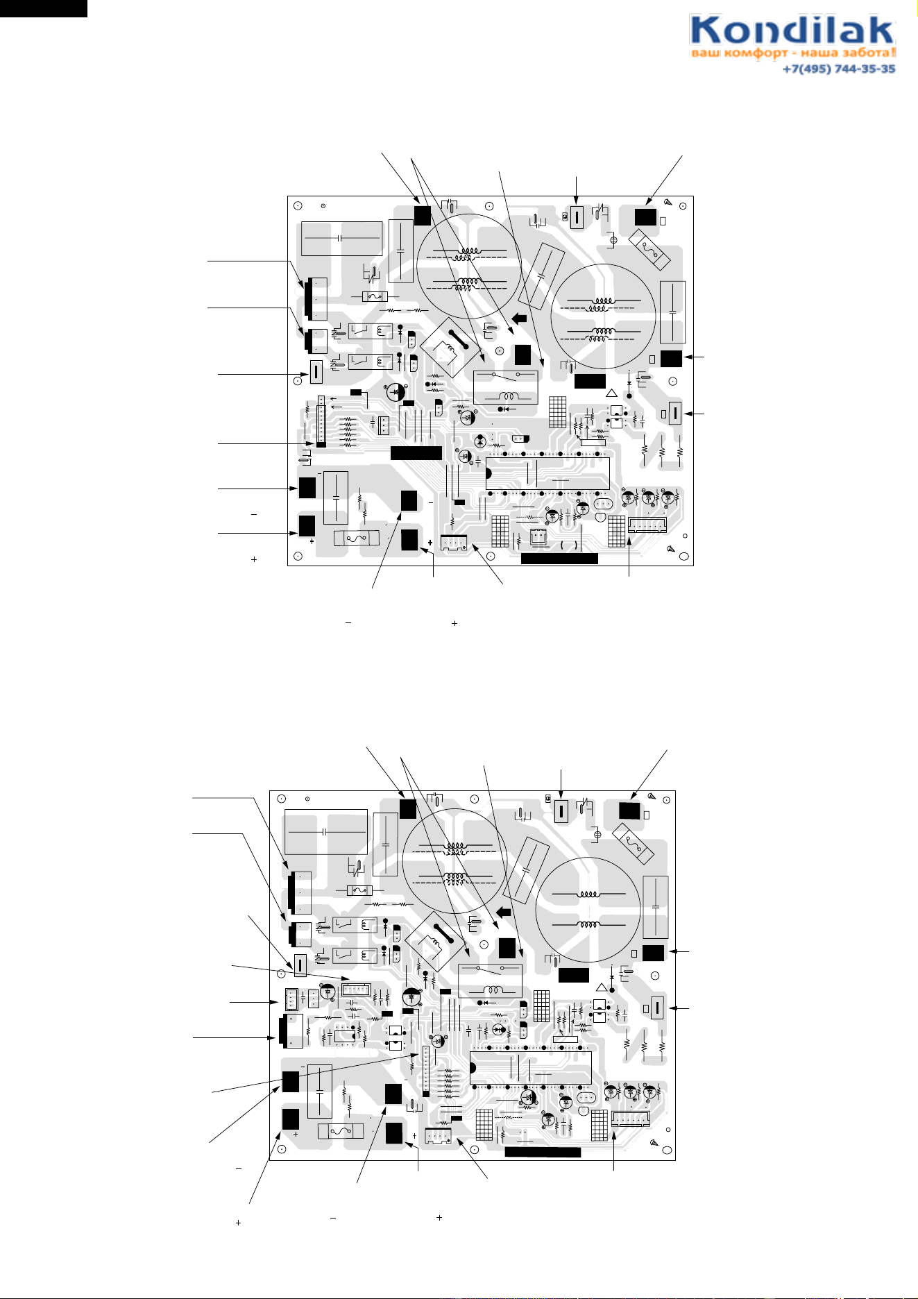
24
AH-X08BE/10BE/13BE
AY-X08BE/10BE/13BE
AY-X08BE-C/10BE-C
AU-X08BE/10BE/13BE
AE-X08BE/10BE/13BE
AE-X08BE-C/10BE-C
Figure L-10 Printed Wiring Board for AU-X08BE/X10BE and AE-X08BE-C/X10BE-C
Figure L-11 Printed Wiring Board for AU-X13BE and AE-X13BE
T5(DB1~)
(BLACK)
C5
NR2
WPE3
R2
R1
CT1
3A 250V
RY1
CNR1
CNR2
RY2
WINTER KIT
(OPTION)
T11
(GRAY)
T10
T9
WPE2
10A
250V
(BLUE)
(YELLOW)
IPM
13V
R33
R32
R31
R30
R29
R28
BCN11 (IPM)
JP2
C32
C10
R40
R39
JP20
JP1
R46
R34
JP14
JP15
JP16
JP12
LED1
JP10
Q3
C33
Q2
Q1
C1
SA1
D7
D6
JP9
JP8
JP7
JP4
JP6
JP5
JP3
IC2
C11
C16
JP21
JP17
JP18
R41
(4-WAY VALVE)
CN4
(FAN MOTOR)
CN3
1
3
1
5
10
12
E&J
V&W2
IPM
(RED)
(BLUE)
T7
CB
T8
CB
WINTER KIT (OPTION)
CN10
JP22
JP19
C17
R35
JP25
C18
C23
R20
C21
R13
R12
R11
C22
C26
R21
R38
R36
F
JP23
JP24
CN912
14
TERMINAL
FUSE
ONLY
W2
IC3
OSC1
R4
C12
C31
D1
R16
C13
R17
JP16
C14
R1
R6
R5
PC2
PC1
C3
3
4
1
2
2
1
4
3
L3
C4
L4
C34
C2
NR1
WPE1
15A 250V
OUT
32
33
IC1
1
CN8
(THERMISTOR)
16
64
R3
C15
R10
D8
JP11
C30
R8
D2
R9
E
C
B
E
C
B
E
C
B
C20
BCE
Q4
Cool/40Hz
QPWBFB397JBZZ
DPWBFA JBKZ
0
MRY1
PTC
(BLUE)
IN
(GRAY)
(DB1~)
(RED)
(BLUE)
(BROWN)
(GREEN/
YELLOW)
T3
T2
2
N
1
T1
T4
DIP
T6(GRAY)
PTC
5V
GND
FROM
FAN MOTOR
FROM
4 WAY VALVE
(EXCEPT FOR
AU-X08BE AND
AUX10BE)
TO
POWER TRANSISTOR
MODULE QM1
OPTION
(FROM WINTER KIT)
FROM
POWER TRANSISTOR
MODULE QM1 " "
FROM
POWER TRANSISTOR
MODULE QM1 " "
FROM
ELECTLYTIC
CAPACITOR
C8 " "
FROM
ELECTLYTIC
CAPACITOR
C8 " "
FROM
THERMISTOR
OPTION
(WINTER KIT)
FROM
TERMINAL
BOARD " N "
FROM
TERMINAL
BOARD " 2 "
FROM
TERMINAL
BOARD " 1 "
FROM
CONTROL BOX
FROM
DIODE BRIDGE
DB1 " ~ "
FROM
DIODE BRIDGE
DB1 " ~ "
FROM
PTC1
T5(DB1~)
(BLACK)
C5
NR2
WPE3
R2
R1
CT1
3A 250V
RY1
CNR2
CNR1
RY2
WINTER KIT
(OPTION)
T11
(GRAY)
T10
T9
WPE2
20A
250V
(BLUE)
(YELLOW)
IPM
R33
R32
R31
R30
R29
R28
C10
C40
R52
OUT
C45
CN14
1
41
CN12
4
IN
IC2
C45
JP23
R50
R40
R39
JP1
R46
C33
Q2
Q1
C1
SA1
D7
D6
JP2
JP17
JP19
JP18
(4-WAY VALVE)
CN4
(FAN MOTOR)
CN3
1
3
1
5
IPM
(RED)
(BLUE)
T7
CB
T8
CB
WINTER KIT (OPTION)
CN10
JP16
JP20
C17
R35
R36
JP25
C18
C23
R20
C21
R13
R12
R11
C22
C26
R21
R38
F
JP21
R10
JP22
14
IC3
C15
OSC1
R4
C12
C31
D1
R16
C13
R17
JP12
R7
C14
JP13
R6
R5
R5
PC2
PC1
C3
3
4
1
2
2
1
4
3
L3
C4
L4
C34
C2
NR1
WPE1
25A 250V
OUT
32
33
32
IC1
1
CN8
(THERMISTOR)
16
64
C20
LED1
R59
D8
C30
E
C
B
E
C
B
B
C
E
B
C
E
Q4
R3
R41
C12
JP7
JP6
R9
D2
R8
JP3
R57
C44
R58
JP5
JP4
R60
121
BCN11 (IPM)
JP8
JP9
JP10
JP11
C16
Q3
Cool/40Hz
QPWBFB388JBZZ
DPWBFA
JBKZ
0
MRY1
PTC
(BLUE)
IN
(GRAY)
(DB1~)
(RED)
(BLUE)
(BROWN)
(GREEN/
YELLOW)
T3
T2
2
N
1
T1
T4
DIP
T6(GRAY)
PTC
2
1
4
3
3
4
1
2
PC4
PC3
R34
C32
JP14
JP15
GND
R53
C41
14
8
IC4
5
R54
C43
61
CN13
18V
13V
R51
5V
FROM
FAN MOTOR
FROM
4 WAY VALVE
(EXCEPT FOR
AU-X13BE)
FROM
ELECTLYTIC
CAPACITOR C8
OPTION
(FROM WINTER KIT)
TO
ACTIVE FILTER
MODULE AF1
TO
TRANSISTOR
MODULE QM1
FROM
POWER TRANSISTOR
MODULE QM1 " "
FROM
POWER TRANSISTOR
MODULE QM1 " "
FROM
ELECTLYTIC
CAPACITOR
C8 " "
FROM
ELECTLYTIC
CAPACITOR
C8 " "
FROM
THERMISTOR
OPTION
(WINTER KIT)
FROM
TERMINAL
BOARD " N "
FROM
TERMINAL
BOARD " 2 "
FROM
TERMINAL
BOARD " 1 "
FROM
CONTROL BOX
FROM
DIODE BRIDGE
DB1 " ~ "
FROM
DIODE BRIDGE
DB1 " ~ "
FROM
PTC1
TO
TRANSISTOR
MODULE QM1
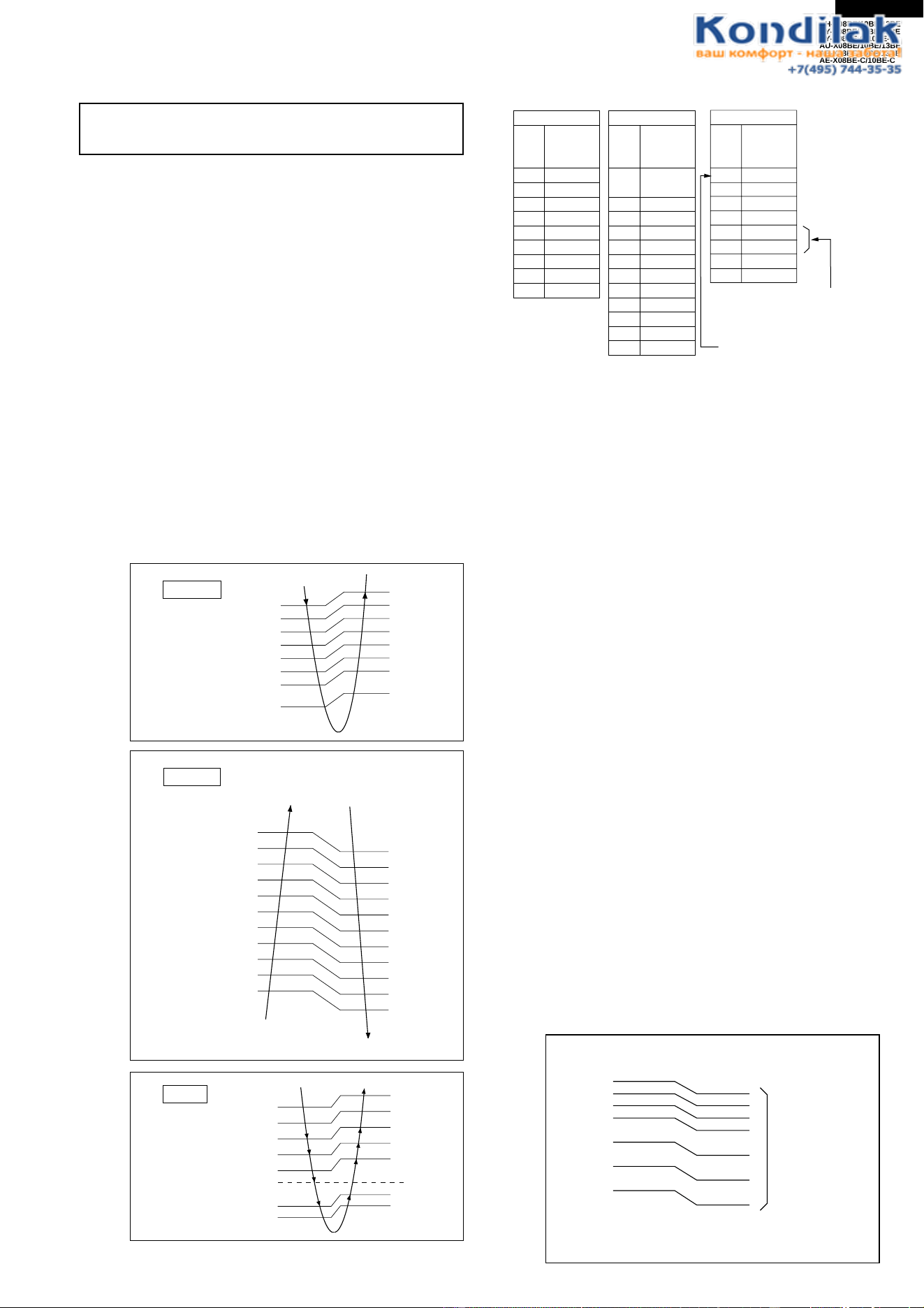
25
AH-X08BE/10BE/13BE
AY-X08BE/10BE/13BE
AY-X08BE-C/10BE-C
AU-X08BE/10BE/13BE
AE-X08BE/10BE/13BE
AE-X08BE-C/10BE-C
AH-X08BE/X10BE/X13BE are not provided with the
heating function.
1. INDOOR UNIT
1-1 Temperature Adjustment
a. Normal control
Proportional control (P control)
When the temperature zone changes, this control
changes the frequency by one rank to move closer
to the set value.
Integral control (I control)
When the temperature zone has set time in the
same zone, this control changes the frequency
by one rank to move closer to the set value.
(Excluding the h zone.)
b. Initial control
The initial frequency is determined as shown in
the tables below based on the difference between
the temperature adjustment setting at the
beginning of operation and the room temperature.
After operation begins, normal control is performed
and therefore the correspondences in the tables
below will not hold.
FUNCTIONS
c. Temperature adjustment
The temperature adjustment range is changed by
changing the operating mode with the operation switch.
(1) Heating
If the room temperature is in the z zone when
operation begins, proportional/integral control is
not performed, and the machine runs at frequency
code c full power until the i zone is reached. When
the i zone is reached, the frequency changes to
the frequency code determined by fuzzy calculation,
and after that proportional/integral control is
performed.
(2) Cooling
If the room temperature is in the c zone when
operation begins,proportional/integral control is not
performed, and the machine runs at frequency
code 9 power until the i zone is reached. When the
h zone is reached, the frequency changes to the
frequency code determined by fuzzy calculation,
and after thatproportional/integral control is
performed.
(3) Dry
After operation begins, 2 minutes (running at the h
zone) of the room temperature is stored in memory,
and that becomes the set value.
(4) Circulation
The frequency code 0 is sent to the outdoor
machine, and only the fan of the indoor machine
runs, the compressor does not run.
1-2 Indoor fan control
This control uses the thermistor for the indoor heat
exchanger to control cold air blowing prevention, the
indoor fan, and overheating prevention.
c
d
e
f
g
h
i
j
k
+3.33
+2.66
SET VALUE
-0.66
-1.66
+0.66
+2.00
Cooling
+1.33
k
j
i
h
g
f
e
d
c
b
a
z
+1.33
+0.66
-1.33
-2.00
SET VALUE
-3.33
-2.67
-4.00
-4.66
-5.33
Heating
-0.66
e
d
g
f
h
j
i
+2.00
+2.66
+1.33
-1.00
+0.66
-1.33
Dry
MEMORY SET VALUE
Cooling
Room
temp.
zone
Frequency
Code
c9
d8
e7
f5
g3
h2
i1
j OFF
k
OFF
Heating
Room
temp.
zone
Frequency
Code
k
OFF
(Hot keep fan)
j1
i1
h2
g3
f4
e5
d6
e7
f5
g3
h2
i1
Dry
Room
temp.
zone
Frequency
Code
e4
d5
f3
g2
h2
h1
1
2
i1
j
0
c
b
a
z
8
A
B
C
Full power
operation only
Although the initial value
of the h zone is 1, it changes
to 2 after a lapse of 15 minutes.
53
50
47
44
38
32
26
H
G
F
E
D
C
B
A
(˚C)
Cold air blowing
prevention line
Temperature of indoor heat exchanger
Differential
3˚C
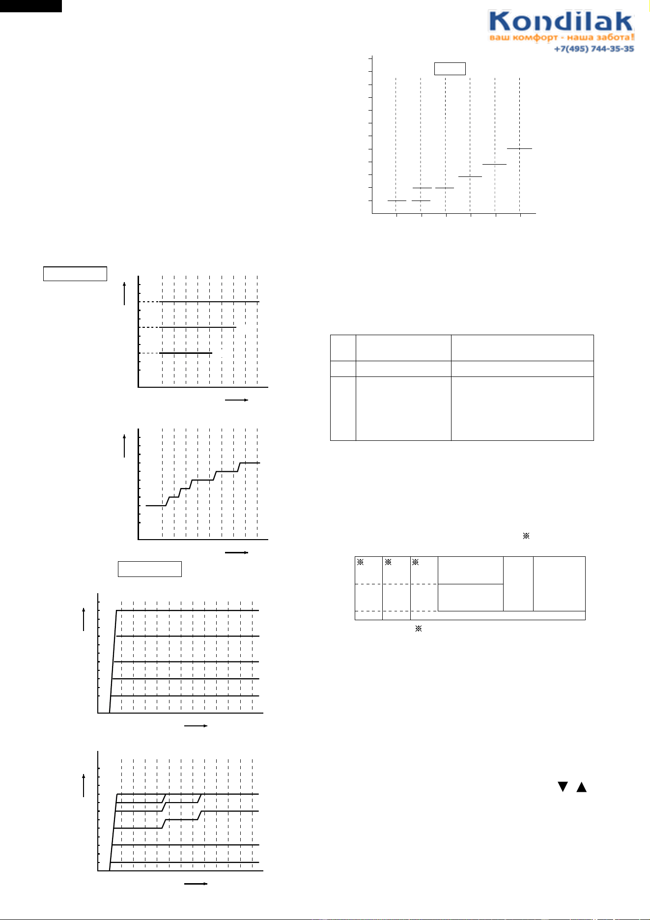
26
AH-X08BE/10BE/13BE
AY-X08BE/10BE/13BE
AY-X08BE-C/10BE-C
AU-X08BE/10BE/13BE
AE-X08BE/10BE/13BE
AE-X08BE-C/10BE-C
(1) Control for indoor freezing prevention
If the temperature of the indoor heat exchanger stays
below approximately 0°C for four minutes during
cooling or dry, this control stops the compressor. Over
2˚C the compressor will run again.
(2) Control for cold air blowing prevention
When heating begins, this control stops the indoor fan
until the temperature of the indoor heat exchanger
reaches 26°C. It also stops the fan if the temperature
goes below 23°C during operation.
(3) Indoor fan and operating frequency
The indoor fan has 12 speeds, and changing is done
in four stages, "Auto", "High", "Med", and "Low". The
relations between the indoor fan speed, air quantity
setting, operating frequency, and indoor heat
exchanger are shown in the following charts.
1-3 Hot keep
If the room temperature is in the j or k zone during
heating, the compressor is turned on and off to
prevent overheating.
The fan goes off 30 seconds after the compressor
goes off.
Zone
Compressor
intermittent time
Fan
After "3 min. on - 3 min.off" is
repeated 4 times, the compressor
goes off, and only the fan
continues to repeat “3 min. on - 8
min.off”.
J
K
3 min. on - 3 min. off
3 min. on - 8 min. off
Same as Compressor
1-4 Automatic operation
The operating mode and temperature setting are
determined by the room temperature and the external
air temperature.
The operating mode will changeover automatically
with the following condition.
OFF
1
2
3
4
5
6
7
8
9
10
11
123456789OFF
Fan speed
Frequency cord
Fan speed : High / Med / Low
High
Med
Low
OFF
1
2
3
4
5
6
7
8
9
10
11
123456789OFF
Fan speed
Frequency cord
Fan speed : Automatic
COOLING
OFF
1
2
3
4
5
6
7
8
9
10
11
123456789OFF
Fan speed
Frequency cord
Fan speed : High / Med / Low
12
A B C
A
B
C
Low
D - H
Med
D - H
High
D - H
OFF
1
2
3
4
5
6
7
8
9
10
11
123456789OFF
Fan speed
Frequency cord
Fan speed : Automatic
12
A B C
A
B
C
D
E, F, G, H
HEATING
1. From cooling to heating
Cooling mode will changeover to heating mode when
condition of indoor temperature 1.7˚C lower than the
set temperature conditions for 5 minutes.
2. From heating to cooling
Heating mode will change over to cooling mode when
condition of indoor temperature 1.3˚C higher than the
set temperature conditions for 25 minutes under Hot
keep condition.
3. When the set temperature is adjusted within the
range of ±2˚C by the remote control's key. ( ),
the changeover judgement room temp. will also be
shifted within the range of ±2˚C.
1-5 ON-timer
The ON-timer is set by pressing the ON-timer button.
In order to attain the set temperature at the set time,
the operation starting time is corrected by fuzzy
computing one hour before the set time.
Heating
(24˚C)
Heating
(23˚C)
Cooling
(24˚C)
Cooling
(24˚C)
(Room temperature
- 2°C)
Cooling
(25˚C)
Cooling
(26˚C)
(Dry)
Room
temperature
(˚C)
When the cooling operation only can use winter kit
21
29
01018 28 34
Outdoor
temperature (°C)
Cooling
(25˚C)
Cooling
(26˚C)
Heating
(22˚C)
12
11
10
9
8
7
6
5
4
3
2
1
01234
5
f
e
d
(Full power only)
j
i
h1 h2, g
Dry
Operating frequency code
Fan speed
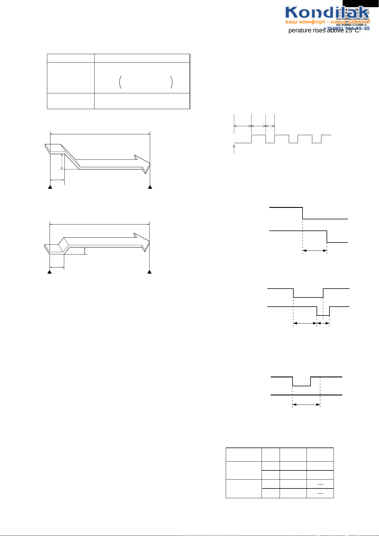
27
AH-X08BE/10BE/13BE
AY-X08BE/10BE/13BE
AY-X08BE-C/10BE-C
AU-X08BE/10BE/13BE
AE-X08BE/10BE/13BE
AE-X08BE-C/10BE-C
ON
OFF
ON
ON
Air conditioner
operation
Compressor
relay
100 sec.
compressor chamber temperature rises above 25°C.
Preheat does not operate for 2 hours after heating
is stopped. After that, it goes on for 180 minutes
and then stops for 30 minutes, repeatedly.
1-12 Power ON start
If a jumper wire is inserted into the place indicated
JP99 on the indoor control board, and the power
plug is inserted. cooling or heating will be
automatically determined by the room temperature
sensor on the main unit, and operation will begin.
1-6 OFF-timer
The OFF-timer is set by pressing the OFF-timer
button. Operation is as follows:
Cooling
Heating
Set temperature
By fuzzy computing
Set the shift up time
Cooling setting + 1°C
Heating setting - 3°C
Final
Dry Same as above
(Final setting + 1°C)
*During Cooling / Dry
1°C
Stops
Timer set time
1
hour
Timer operation starts
Room
temperature
3°C
Room
temperature
Timer set time
1
hour
Timer operation starts Stops
1-7 Swing louvres
Louvres are moved by a stepping motors to perform
swing and fixing in the set position. If the "FLOW
DIRECTION" button is pressed during swing, they
will stop. If the "FLOW DIRECTION" button is pressed
while they are stopped, they will swing.
1-8 Restart control
Once the compressor stops, this control prevents it
from starting again for 3 minutes. It also prevents
starting for 80 seconds immediately following plugging
into the power outlet.
1-9 One-hour operation
If this button is pressed when operation is stopped,
operation will begin and then stop after 1 hour. If
pressed when it is operating, will stop after one hour.
1-10 Full power operation
Immediately begins cooling or heating at maximum
power and air flow.
(During heating) Operates at setting of 32°C.
(During cooling) Operates at setting of 18°C.
1-11 Preheat
When heating is stopped, supplies a small amount
of power to the compressor to make heating start
more quickly. Operates when the indoor temperature
sensor and external air sensor detect that the room
temperature and outdoor temperature are low (below
18°C and 5°C, respectively). Stops when the
30
min
180
min
At least
120 min
Air conditioner OFF
ON
OFF
OFF
Air conditioner
operation
Compressor
relay
100 sec.
ON
ON
ON
OFF
ON
OFF
Air conditioner
operation
Compressor
relay
100 sec.
80 sec.
ON
*During Heating
1-13 Compressor relay
(1) It is ON during operation, and when operation is
stopped, goes OFF after a delay of 100 seconds
(not immediately).
Power
select
Cooling Heating
H 7.9A 10.5A
7.7A 7.2A
7.9A
7.7A
L
AY-X13BE
AH-X13BE
H
L
(3) If air conditioner operation is turned on again
during the 100 second delay before the
compressor relay goes off, the compressor relay
will stay on.
(2) The minimum OFF time of the relay is 80 seconds.
It will not go ON again before 80 seconds elapses.
1-14 Power selector (AY-X13BE, AH-X13BE)
Operation power "H " (High) or "L" (Low) can be
selected by switching the POWER SELECTOR
slide switch located above the AUX. button.
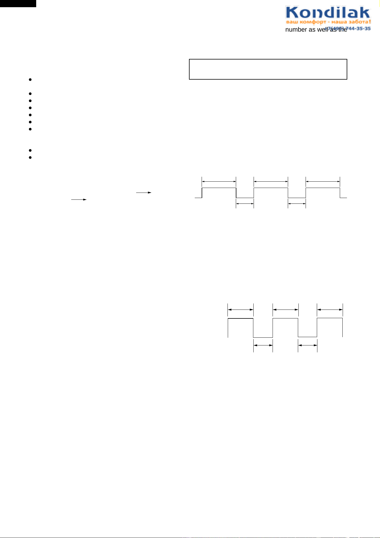
28
AH-X08BE/10BE/13BE
AY-X08BE/10BE/13BE
AY-X08BE-C/10BE-C
AU-X08BE/10BE/13BE
AE-X08BE/10BE/13BE
AE-X08BE-C/10BE-C
informed by the flashing number as well as the
lighting pattern of the operation lamp which
flashes with the timer lamp.(For details, refer to
Error diagnostic method.)
AU-X08BE/10BE/13BE are not provided with
the heating function.
2. OUTDOOR UNIT
2-1 Defrost operation
(AE-X08BE/X08BE-C/X10BE/X10BE-C/13BE)
(1) Overview
Defrosting begins during heating if the conditions for
compressor operation time and outdoor heat
exchanger temperature are met.
When defrosting begins, the indoor and outdoor fans
stop. Defrosting stops when the temperature of the
outdoor heat exchanger goes above approximately
5˚C or defrosting time exceeds 13 minutes.
1-15 Auto Restart
When power failure occures, after power is
recovered, the unit will automatically restart in the
same setting which were active before the power
failure.
Operating mode (Cool, Heat, Dry)
Temperature adjustment (within 2˚C range)
automatic operation
Temperature setting
Fan setting
Air flow direction
Power ON/OFF
Automatic operation mode setting
Swing louver
Setting not memorized
Timer setting
Full power setting
1-16 Indoor/outdoor temperature display
Every time the Temperature check button is
pressed on the remote control, the display changes
in the order of indoor temperature outdoor
temperature no display. The temperature is
displayed on the temperature indicator on the main
unit to be referred to for energy saving.
(When the unit is not running, the display changes
between indoor temperature and no display.)Indoor
temperature is the temperature of the suction air
measured by the room thermistor, and outdoor
temperature is that measured by the outdoor
temperature thermistor. When indoor temperature
is displayed, the indoor LED on the main unit is lit,
and when outdoor temperature is displayed, the
outdoor LED is lit. For 90 seconds after the
operation starts, - - is displayed instead of the
actual outdoor temperature since it is still being
measured.Because of the effect of the exchanger,
the unit cannot confirm the exact indoor
temperature right after the operation is terminated.
Therefore, for one hour since the operation is
stopped, the indoor temperature immediately
before the operation is stopped is displayed. After
over one hour since it is stopped, the unit displays
the actual room temperature at that point.
1-17 Error diagnostic display
(a) Indoor unit
(1) When an error is detected, all relays are
turned off. At the same time, the details of the
error are displayed by flashing the number
corresponding to the type of the error. The
details can also be displayed by pressing down
the emergency operation switch for 5 seconds
or more in the state of operation stop.However,
if the operation is continued only in the serial
open state and the state remains unchanged
after that, the main relay is turned off in 8
minutes. In the serial short state, the error is
not displayed and the operation is continued. If
the unit stays in the same state, the main relay
is turned off in 8 minutes. Although the error is
not displayed, it is memorized and can be
displayed when it is recalled.
(2) If the operation is stopped and the emergency
operation button is pressed down for 5 seconds
or more, the self-diagnosis memory can be
recalled.
(3) Details of self-diagnosis (error mode) are
Defrost
mask time
Defrost
mask time
Defrost
mask time
Heating
begins
Defrosting
Max. 13 min.
Defrosting
Max. 13 min.
More than
20 min.
More than
20 min.
Defrosting
Max. 12 min.
Heating
operation
start
Defrosting
Max. 12 min.
More than
20 min.
(3) During defrosting
When defrosting begins, the compressor stops.
Approximately 1 minutes later, the compressor
reactivates in the refrigeration cycle, and the outdoor
heat exchanger is defrosted.
Each mode is as follows:
The outdoor fan is stopped
The operating frequency is as shown in the table
below The indoor fan is stopped
(4) Defrost stop
When defrosting time exceeds 13 minutes When the
temperature of the outdoor heat exchanger rises
above approximately 5˚C Defrost stop is determined
by either of the above conditions, and the compressor
is stopped. At the same time, the outdoor fan go ON.
The compressor is reactivated in the heating cycle 1
minute after it was stopped, and normal control
resumes.
2) Defrosting
If the compressor operation time is more than 20
minutes in the heating mode and the outdoor air
temperature and outdoor heat exchange temperature
satisfy the defrosting conditions, the defrosting
operation is started.
When the outdoor sheat-exchanger temperature
reaches approx. 5°C or above or when the defrosting
time exceeds 12 minutes, the defrosting operation is
quit.
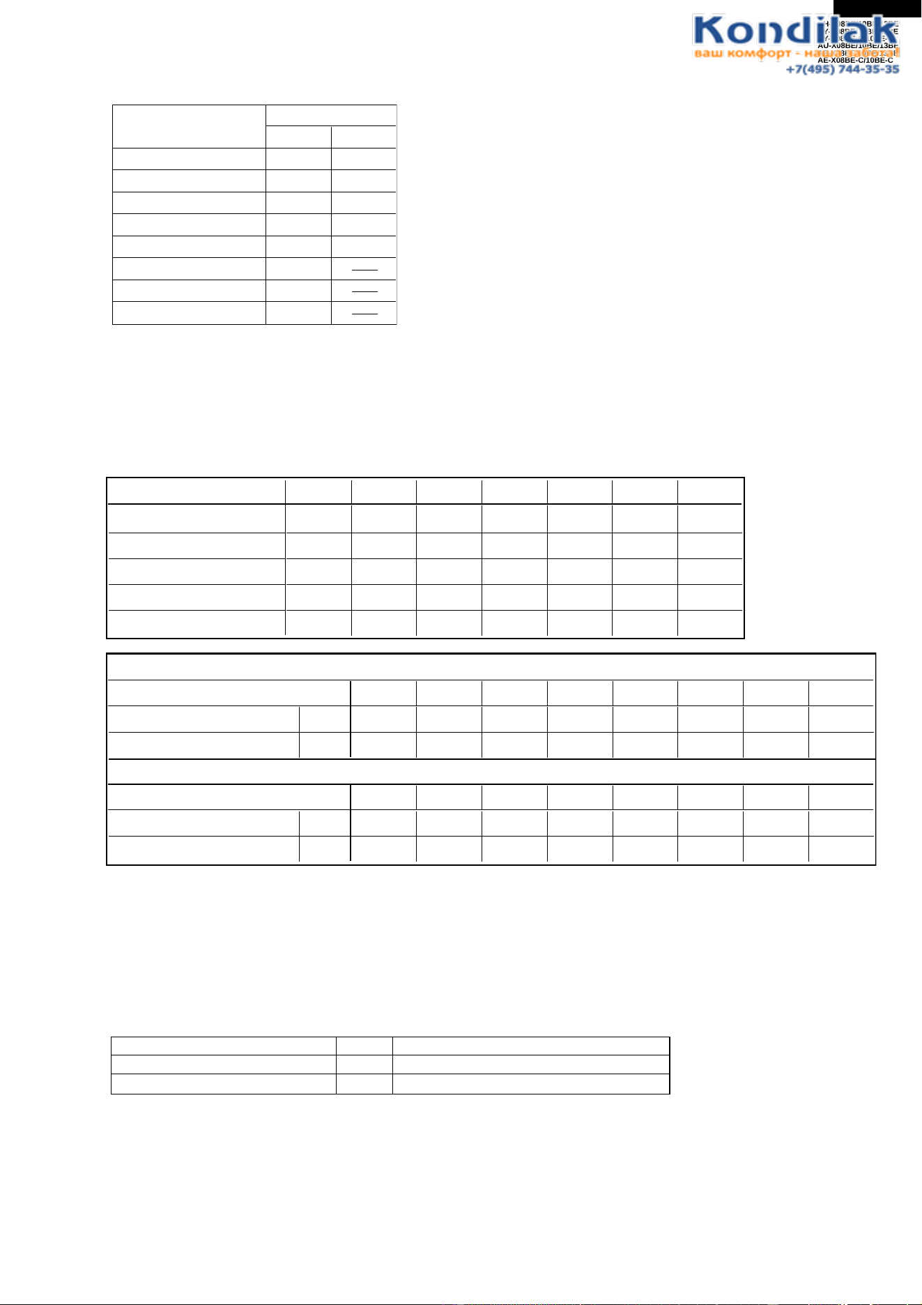
29
AH-X08BE/10BE/13BE
AY-X08BE/10BE/13BE
AY-X08BE-C/10BE-C
AU-X08BE/10BE/13BE
AE-X08BE/10BE/13BE
AE-X08BE-C/10BE-C
2-2 Frequency control
(1) AC current peak control
(2) Control for prevention of indoor heat exchanger overheating. If the temperature of the indoor heat exchanger
exceeds the overheating prevention line 1 or 2 during heating, the operating frequency is lowered by approximately
5 to 10 Hz. After that, the frequency is lowered by approximately 5Hz once every 60 seconds or 10 Hz once every
120 seconds. When the temperature of the indoor heat exchanger goes below the overheating prevention line 1,
the frequency is raised by approximately 5 Hz once every 60 seconds, and normal operation is restored.
If the frequency is lowered to minimum frequency without the temperature of the outdoor heat exchanger
decreasing and this condition lasts for 1 minute, the compressor will be stopped.
(3) Control for prevention of outdoor heat exchanger overheating. If the temperature of the outdoor heat exchanger
exceeds the overheating prevention lone 1 or 2 during cooling, the operating frequency is lowered by approximately
5 to 15 Hz.
After that, the frequency is lowered by approximately 5 once every 60 seconds or approximately 15Hz once every
120 seconds. When the temperature of the outdoor heat exchanger goes below the overheating prevention clear
line, the frequency is raised by approximately 5 Hz once every 60 seconds, and normal operation is restored. If the
frequency is lowered to minimum frequency without the temperature of the outdoor heat exchanger decreasing and
this condition lasts for 1 minute, the compressor will be stopped.
4) Control for prevention of discharge overheating
If the discharge temperature exceeds approximately (AU-X13BE:101°C except AU-X13BE:105°C) during compressor
operation, the operating frequency is lowered by approximately 5 Hz. After that, the frequency is lowered by
approximately 5 Hz once every 60 seconds. When the discharge temperature goes below approximately (AU-
X13BE:100°C except AU-X13BE:104°C) , the frequency is raised by approximately 5 Hz once every 60 seconds,
and normal operation is restored.
If the frequency is lowered to minimum frequencywithout the discharge temperature decreasing and this condition
lasts for 1 minute, the compressor will be stopped.
Frequency A B C D E F G
AE-X08BE 92 88 83 75 50 43 37
AE-X10BE 120 113 107 100 50 43 37
AE-X13BE 120 113 107 100 50 43 37
AE-X08BE-C 101 100 90 85 50 45 40
AE-X10BE-C 114 109 103 97 50 43 37
A~ A~B B~C C~D D~E E~F F~G ~G
A~ A~B B~C C~D D~E E~F F~G ~G
During normal operation
[°C]
[°C]
[°C]
[°C]
46.11 49.59 51.87 53.29 54.26 53.29 52.34 51.41
During full power operation 49.14 51.87 54.75 56.25 58.32 56.76 55.74 54.26
During normal operation 48.26 51.87 51.87 55.24 56.25 55.24 54.26 53.29
During full power operation 51.41 51.87 53.77 58.32 59.94 58.32 57.27 56.25
Operating Frequency
Operating Frequency
Overheating prevention line 1(Lower 5Hz)
Overheating prevention line 2(Lower 10Hz)
56˚C
58˚C
55˚C
Lower 5Hz once every 60 seconds
Lower 15Hz once every 120 seconds
Overheating prevention line 1
Overheating prevention line 1
Overheating prevention line 1
Model
Set valve
Cool Heat
6.0A 7.5A
5.0A 5.5A
7.0A 8.5A
5.0A
5.5A
7.0A
AE-X08BE
AE-X10BE
4.3A 4.5A
AE-X08BE-C
5.2A 5.7A
AE-X10BE-C
AE-X13BE
AU-X08BE
AU-X10BE
AU-X13BE

30
AH-X08BE/10BE/13BE
AY-X08BE/10BE/13BE
AY-X08BE-C/10BE-C
AU-X08BE/10BE/13BE
AE-X08BE/10BE/13BE
AE-X08BE-C/10BE-C
(5) Control for prevention of indoor heat exchanger freezing
If the temperature of the indoor heat exchanger goes below approximately 5°C during cooling(only Full power
operation), the operating frequency is lowered by approximately 5 Hz. After that, the frequency is lowered by
approximately 5 Hz once every 60 seconds. When the temperature of the indoor heat exchanger rises above
approximately 5°C, the frequency is raised by approximately 5 Hz once every 60 seconds, and normal operation is
restored.
If the temperature of the indoor heat exchanger goes down to approximately 0°C and this condition continues for
4 minutes, the compressor is stopped.
When the temperature rises above approximately 2˚C, normal operation is restored.
2-3 Overcurrent protection
(1) Compressor lock detection
If the set value (AE-X08BE/X10BE/X13BE: 2.7A,AE-X08BE-C/X10BE-C: 2.7A, AU-X08BE/X10BE/X13BE: 2.7A)
of AC current is exceeded in 6 seconds when operation begins, operation is stopped. In this case, the compressor
outdoor fan does not stop, and 170 seconds after operation is stopped, another try will be made. Three retries are
allowed. On the fourth retry, a complete stop request signal is sent to the indoor unit, and the outdoor unit will
remain stopped until reset is performed. At this time, the 3-minute delay for control of the outdoor unit will not
function; therefore, do not cancel by removing the plug and cutting the power.
(2) DC overcurrent detection, AC overcurrent detection
To protect against overcurrent due to sudden changes in load, the compressor is stopped if the set value (AE-
X08BE/X10BE. AE-X08BE-C/X10BE-C. AU-X08BE/10BE: 26A, AE-X13BE. AU-X13BE: 47A) DC is exceeded in
the DC section, or the set value (AE-X08/10BE. AE-X08-C/10BE-C. AU-X08/10BE: 11A, AE-X13BE. AU-X13BE:
13A) AC is exceeded in the AC section. In this case, the outdoor fan does not stop, and 170 seconds after
operation is stopped, another try will be made. Three retries are allowed. On the fourth retry, a complete stop
request signal is sent to the indoor unit, and the outdoor unit will remain stopped until reset is performed. At this
time, the 3-minute delay for control of the outdoor unit will not function; therefore, do not cancel by removing the
plug and cutting the power.
2-4 Compressor protector control
If the temperature of the compressor chamber exceeds 114°C, the compressor is stopped. In this case, the outdoor
fan does not stop, and when the compressor chamber temperature decreases to 100°C three minutes after
operation is stopped, another try will be made. Three retries are allowed. On the fourth retry, a complete stop
request signal is sent to the indoor unit, and the outdoor unit will remain stopped until reset is performed. At this
time, the 3-minute delay for control of the outdoor unit will not function; therefore, do not cancel by removing the
plug and cutting the power.
2-5 Power transistor module protector
If the temperature of the chips in the power transistor module exceeds 105 °C, the compressor is stopped.
In this case, the outdoor fan does not stop, and when the temperature of the chips in the power transistor module
decreases to 105 °C 170 seconds seconds after operation is stopped, another try will be made.
Three retries are allowed. On the fourth retry, a complete stop request signal is sent to the indoor unit, and the
outdoor unit will remain stopped until reset is performed. At this time, the 3-minute delay for control of the outdoor
unit will not function; therefore, do not cancel by removing the plug and cutting the power.
2-6 Power factor module
(AE-X08BE/X08BE-C, AE-X10BE/X10BE-C, AU-X08BE, AU-X10BE)
If a voltage error (over 400 V), current error (over 17 A), or temperature error (over 90°C) is detected in the power
factor module, 170 seconds the compressor is stopped.
(AE-X13BE, AU-X13BE)
If a voltage error (over 420V) is detected at power factor module output voltage, 170seconds the compressor is
stopped.
In this case, the outdoor fan does not stop, and 170 seconds after operation is stopped, another try will be made.
Three retries are allowed. On the fourth retry, a complete stop request signal is sent to the indoor unit, and the
outdoor unit will remain stopped until reset is performed. At this time, the 3-minute delay for control of the outdoor
unit will not function; therefore, do not cancel by removing the plug and cutting the power.
2-7 Serial signals
(1) Serial signals consist of all 96-bit signals.
(2) If the outdoor unit does not receive a serial signal, it will stop approximately 30 seconds later. Note that this is true
only of normal operation; in test mode, it does not stop and operation takes place based on the test mode
commands.
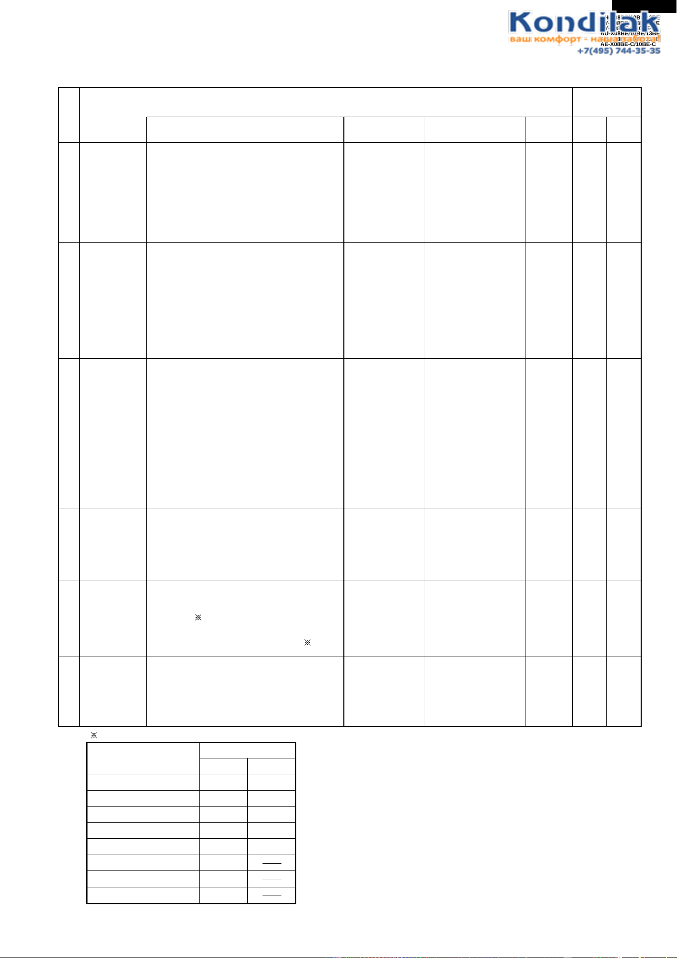
31
AH-X08BE/10BE/13BE
AY-X08BE/10BE/13BE
AY-X08BE-C/10BE-C
AU-X08BE/10BE/13BE
AE-X08BE/10BE/13BE
AE-X08BE-C/10BE-C
FUNCTION AND OPERATION OF PROTECTIVE PROCEDURES
Model
Set valve
Cool Heat
6.0A 7.5A
5.0A 5.5A
7.0A 8.5A
5.0A
5.5A
7.0A
AE-X08BE
AE-X10BE
4.3A 4.5A
AE-X08BE-C
5.2A 5.7A
AE-X10BE-C
AE-X13BE
AU-X08BE
AU-X10BE
AU-X13BE
Function
NO
Description Detection
time
Restart
condition
Restart
times
Indoor
Outdoor
Operation Self diagnostic
display
1
2
3
4
5
6
Indoor fan
lock
Indoor fan
rpm error
Indoor
freezing
guard
Indoor
overheating
control
DC
overcurrent
AC
overcurrent
Compressor
lock
Stops operation if no revolution pulse
signal is input from the indoor fan motor for
one minute.
Stops operation if the revolution pulse
signal from the indoor fan indicates low
rpm (approximately 300 rpm or less).
Lowers the operating frequency if the
temperature of the indoor heat exchanger
goes below 5°C during cooling. Stops the
compressor if the temperature stays below
0°C for 4 minutes.
Lowers the operating frequency if the
temperature of the indoor heat exchanger
rises above the overheating temperature
during heating. Stops the compressor if the
temperature stays above the overheating
temperature for 1 minute at minimum
frequency or less.
Set values for overheating temperature
During normal operation: 46°C to 54°C
During full power operation: 49°C to
58°C
Stops the compressor if a current of
approximately 47/26A or more flows in the
power transistor module. Also stops the
compressor if the temperature of the
power transistor module is exceeds 105°C.
Lowers the operating frequency if the
compressor AC current exceeds
set valve( ).Show "2-2(1)AC peak control"
Stops the compressor if the current
exceeds at 40Hz or less set valve( ).
Stops the compressor if the compressor
AC current exceeds (AE-X08BE/X10BE.
AE-X08BE-C/X10BE-C. AU-X08BE/10BE:
26A, AE-X13BE. AU-X13BE: 47A)
immediately after activating the
When indoor
fan is revolving
During cooling
and dry
During heating
During
compressor
operation
During
compressor
operation
Immediately
after
compressor
activation.
Operation OFF
Automatically
restarts when the
exchange
temperature rises
above the freezing
prevention
temperature (above
2°C)
Automatically
restarts when the
exchange
temperature goes
below the
overheating
temperature.
Automatically
restarts after safety
time (170 seconds)
Automatically
restarts after safety
time (170 seconds)
Automatically
restarts after safety
time (170 seconds)
No limit
No limit
No limit
4 times
4 times
4 times
Yes
No
No
Yes
Yes
Yes
No
No
No
Yes
Yes
Yes
( )
32
AH-X08BE/10BE/13BE
AY-X08BE/10BE/13BE
AY-X08BE-C/10BE-C
AU-X08BE/10BE/13BE
AE-X08BE/10BE/13BE
AE-X08BE-C/10BE-C
Function
NO
Description Detection
time
Restart
condition
Restart
times
Indoor
Outdoor
Operation Self diagnostic
display
7
8
9
10
11
12
13
14
Compressor
overheating
control
Compressor
high
temperature
error
Outdoor heat
exchanger
overheating
control
Outdoor
thermistor
short
Outdoor
thermistor
open
AC abnormal
current error
Serial signal
error
Power factor
module
(Active filter)
error
Lowers the operating frequency if the
temperature of the compressor chamber
thermistor (TH1) rises above 105°C or
101°C.
Stops the compressor if the thermistor
stays above 105°C or 101°C for 1 minutes
at minimum frequency or less.
Stops the compressor if the compressor
chamber thermistor is above 114°C.
(Or when TH1 shorts)
Lowers the operating frequency if the
temperature of the outdoor heat exchanger
rises above 56°C during cooling. Stops the
compressor if the temperature stays above
56°C for 1 minute at minumum frequency.
Stops the compressor if an outdoor
thermistor (excluding TH1) shorts.
Stops the compressor if the circuit of an
outdoor thermistor breaks.
Stops the compressor if if the operating
frequency is above 70 Hz and the
compressor current is below 1.0 A.
Turns the compressor relay off if the indoor
unit does not receive a serial signal from
the outdoor unit for 8 minutes.
Stops the compressor if the outdoor unit
does not receive a serial signal from the
indoor unit for 30 seconds.
When an power factor module error input
is detected.
During
compressor
operation
During
operation
During
compressor
operation
When
compressor is
activated
When
compressor is
activated
During
compressor
operation
During
operation
During
operation
During
compressor
operation
Automatically
restarts after safety
time (170 seconds)
Automatically
restarts when
thermistor (TH1)
temperature falls
below 100°C
(approximately 30
minutes)
Automatically
restarts after safety
time (170 seconds)
Automatically
restarts after safety
time (170 seconds)
Automatically
restarts after safety
time (170 seconds)
Automatically
restarts after safety
time (170 seconds)
Automatically
restarts less than 8
minutes after
operation stops
Restarts after
reception of serial
signal
Automatically
restarts after safety
time (170 seconds)
No limit
4 times
No limit
4 times
4 times
4 times
No limit
No limit
4 times
No
Yes
No
Yes
Yes
Yes
Yes
Yes
No
Yes
No
Yes
Yes
Yes
Yes
Yes
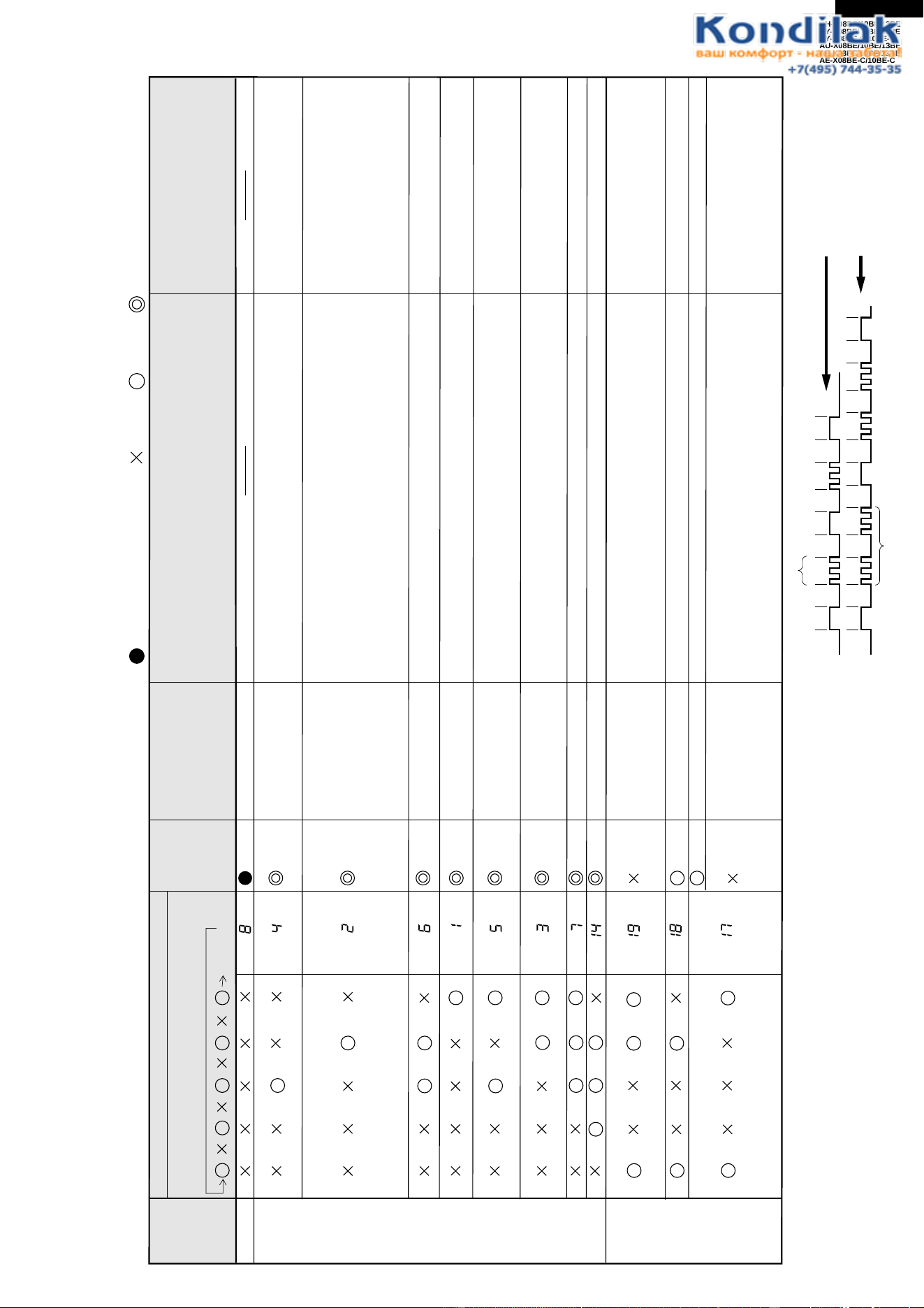
33
AH-X08BE/10BE/13BE
AY-X08BE/10BE/13BE
AY-X08BE-C/10BE-C
AU-X08BE/10BE/13BE
AE-X08BE/10BE/13BE
AE-X08BE-C/10BE-C
: Blinks at 2-second intervals : OFF : ON : Blinks 3 times at 0.2-second intervals
Indoor and outdoor unit
completely stopped
Indoor unit
operating
Outdoor unit
completely stopped
Display by indoor unit operation lamp
Displayed in a pattern which comes on at the same
time as the timer lamp
4 seconds off
What to check, procedure
Display by
outdoor
unit lamp
LED 1
Diagnosis
Solution
Condition
of indoor
and
outdoor
unit
Normal
Once
Twice
3 times
4 times
5 times
6 times
7 times
Compressor lock error
DC overcurrent error
AC overcurrent error
Normal
Serial short
Serial open
Does compressor active ? Does it go off immediately after active ?
1. Check the circuit in the power transistor module.
2. Is the outdoor fan revolving ?
1. Is the discharge outlet of the outdoor unit clogged ?
1. Check the wiring between units.
1. Check the wiring between units.
1. Check the wiring between units.
2. Check the fuse in the outdoor unit.
3. Indoor control board.
4. Outdoor control board.
1. Measure the resistance of thermistor TH2 on the outdoor unit
(see Figure 2).
1. Replace power transistor
module
1. Clear the discharge outlet.
11 times Power factor module error
1. CHeck wiring of power factor module.
1. Replace the power factor module.
1. Rewire.
1. Rewire.
Indoor fan out of order
1. Is the fan motor locked ?
2. Is the wiring connector firmly fitted ?
3. Is the speed signal applied to the motor ?
Overheat of the comp-
ressor error
(protector operating) or
outdoor compressor
thermistor TH1 short
Outdoor power supply
does't turn on.
Wiring mistake.
1. Rewire.
2. Replace the fuse, replace the
outdoor board assembly.
3. Replace the board.
4. Replace the board.
1. Replace fan motor
2. Reattach.
3. Replace the indoor control board
assembly.
1. Replace the outdoor control board
assembly
(Current transformer wire break.)
1. Reattach.
2. Replace the outdoor thermistor
assembly.
1. Replace the outdoor thermistor
assembly.
1. Clear the discharge outlet.
2. Assure power supply voltage.
3. Refill to rated amount.
4. Replace the outdoor ther-mistor
assembly.
5. Replace the indoor control board
assembly or only TH2.
1. Apply an external shock to the
compressor.
2. Replace the compressor.
1. Can voltage be detected at the current transformer on the outdoor
unit control board?
1. Are the connectors of the outdoor unit thermistors well attached ?
2. Measure the resistance of thermistors TH1 and TH2 on the
outdoor unit (see Figure 2).
1. Is the discharge outlet of the outdoor unit clogged ?
2. Is the power supply voltage at least 198 V at full power operation ?
3. Check for refrigerant leaks at the tubing connections.
4. Measure the resistance of compressor thermistor TH1 on the
outdoor unit (see Figure 2).
5. Measure the resistance of heat exchanger pipe thermistor TH2 on
the indoor unit (see Figure 1).
AC abnormal current
error
Open circuit of the
thermistor error
Short circuit of the
thermistor error
1
sec..
1
sec
0.6
sec.
1
sec.
1
sec.
1
sec.
1
sec.
1
sec.
0.6
sec.
1
sec.
1
sec.
1
sec.
1
sec.
1
sec.
1
sec.
Compressor lod
1
sec.
1
sec.
1
sec.
Overheat of the compressor
0.6
sec.
0.6
sec.
1
sec.
0.6
sec.
1
sec.
0.6
sec.
1 time
2 times
ON
OFF
ON
OFF
BREAK DOWN DIAGNOSIS PROCEDURE
Self-diagnostic procedure using display mode
If the timer lamp blinks during operation, the problem can be diagnosed using
the following table.
Note: 1. Normal : Only the timer lamp blinks. Error : Displayed by blinking of run
lamp (above table).
2. If the power plug is removed from the outlet or the breaker is switched to
"OFF", the self-diagnostic memory will be erased.
3. Example of outdoor unit LED 1 blinking :
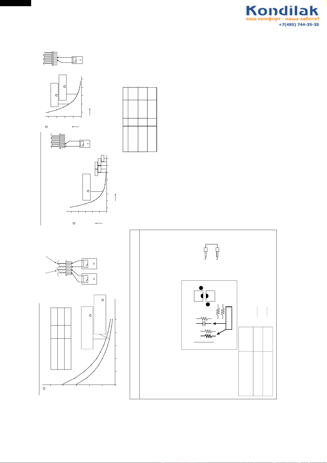
34
AH-X08BE/10BE/13BE
AY-X08BE/10BE/13BE
AY-X08BE-C/10BE-C
AU-X08BE/10BE/13BE
AE-X08BE/10BE/13BE
AE-X08BE-C/10BE-C
100
80
60
40
20
0
-100 10203040
Resistance
Thermistor
Room temperature
Heat exchange
Color
Yellow
Orange
To measure the resistance, first remove
the connector as shown at right.
Room temperature
thermistor TH1
Tester
Signal
CN7
CN7
Figure 1 Temperature properties of indoor thermistors
500K
400K
300K
200K
100K
0
-20 0 20 60 80 100 120
3.06K5.78K
4.17K 2.28K
1.72K
16
40K
30K
20K
10K
0
-20 0 20 60
40
16
Figure 2 Temperature properties of outdoor thermistors
Connector
CN8
TH2 Heat exchange thermistor
TH3 Outdoor temp. thermistor
TH1 compressor thermistor
TH2,TH3
Connector
CN8
Temperature (°C)
Temperature (°C)
Tester
Tester
Thermistor To measure the
resistance, first
remove the
connector from the
board.
ColorNo. Connector
Compressor
thermistor
Heat exchanger
pipe thermistor
Outdoor temp.
thermistor
TH1
TH2
TH3
No. 1 to 2
No. 3 to 4
Red
Orange
No. 5 to 6
Green
Microcomputer
terminal
Input
signal
To Outdoor control board
Adaptor
(C14 )
(GND)
(R17)
Pin No. 43
Pin No. 42
0
1
0 Low input
1 High input
K
Heat exchange thermistor
TH2 (orange)
25°C resistance 15 K
Room temperature
thermistor TH1 (yellow)
25°C resistance 10 K
25°C resistance
45 K
Resistance ( )
Resistance ( )
0°C resistance
14.5 K
25°C resistance
4.431 K
Heat exchange
thermistor TH2
Tester
41
Cautions when attaching or removing the board
When operating only the outdoor unit (cooling 40 Hz fixed mode) To make
only the outdoor unit run in cooling mode, short the places marked with
arrows below with an adaptor, and apply a voltage of 220 ~ 240 V AC to 1
and N on the terminal board.
(Avoid operating the outdoor unit alone for long periods of time.)
PC1
PC2
R6
R5
R7
R16
R17
JP21
C14
Cool / 40Hz
3
4
1
2
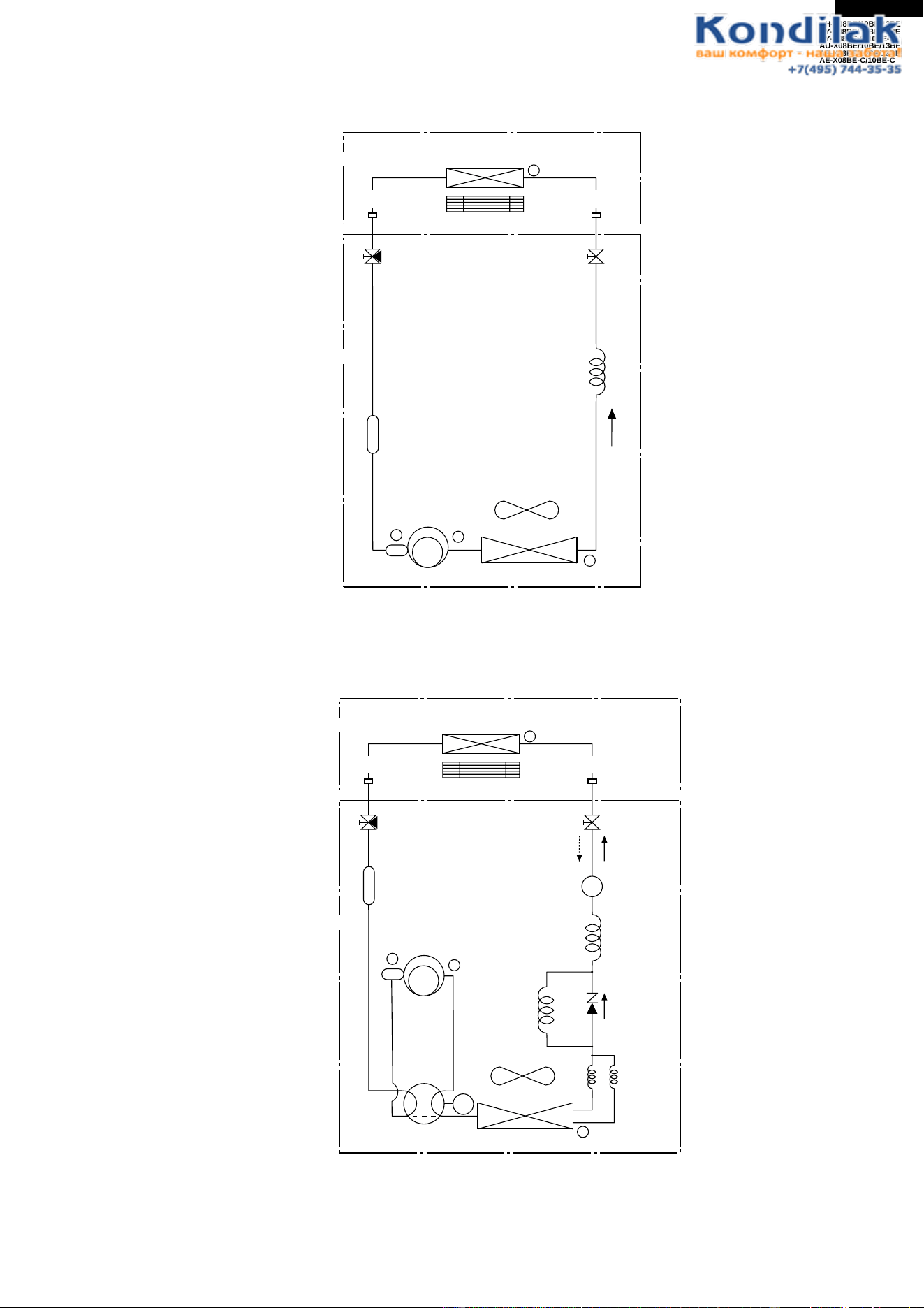
35
AH-X08BE/10BE/13BE
AY-X08BE/10BE/13BE
AY-X08BE-C/10BE-C
AU-X08BE/10BE/13BE
AE-X08BE/10BE/13BE
AE-X08BE-C/10BE-C
REFRIGERATION CYCLE
Figure R-1. Refrigeration Cycle for AH-X08BE/10BE/13BE
Figure R-2. Refrigeration Cyclefor AY-X08BE/X08BE-C/10BE/10BE-C/13BE
1
2
Capillary tube
3
Outdoor unit
Condenser
Evaporator
Indoor unit
Compressor
Flare coupling Flare coupling
Silencer
4
3-way
valve
2-way
valve
Accumulator
s
1
4
C
2
Capillary
tube A
Capillary
tube B
Capillary
tube C
(2 pieces)
Accumulator
3
Strainer
Heating Cooling
Outdoor unit
Condenser
Evaporator
Indoor unit
Reverse valve
Comp-
ressor
Flare coupling Flare coupling
3-way
valve
2-way
valve
Silencer
Coil
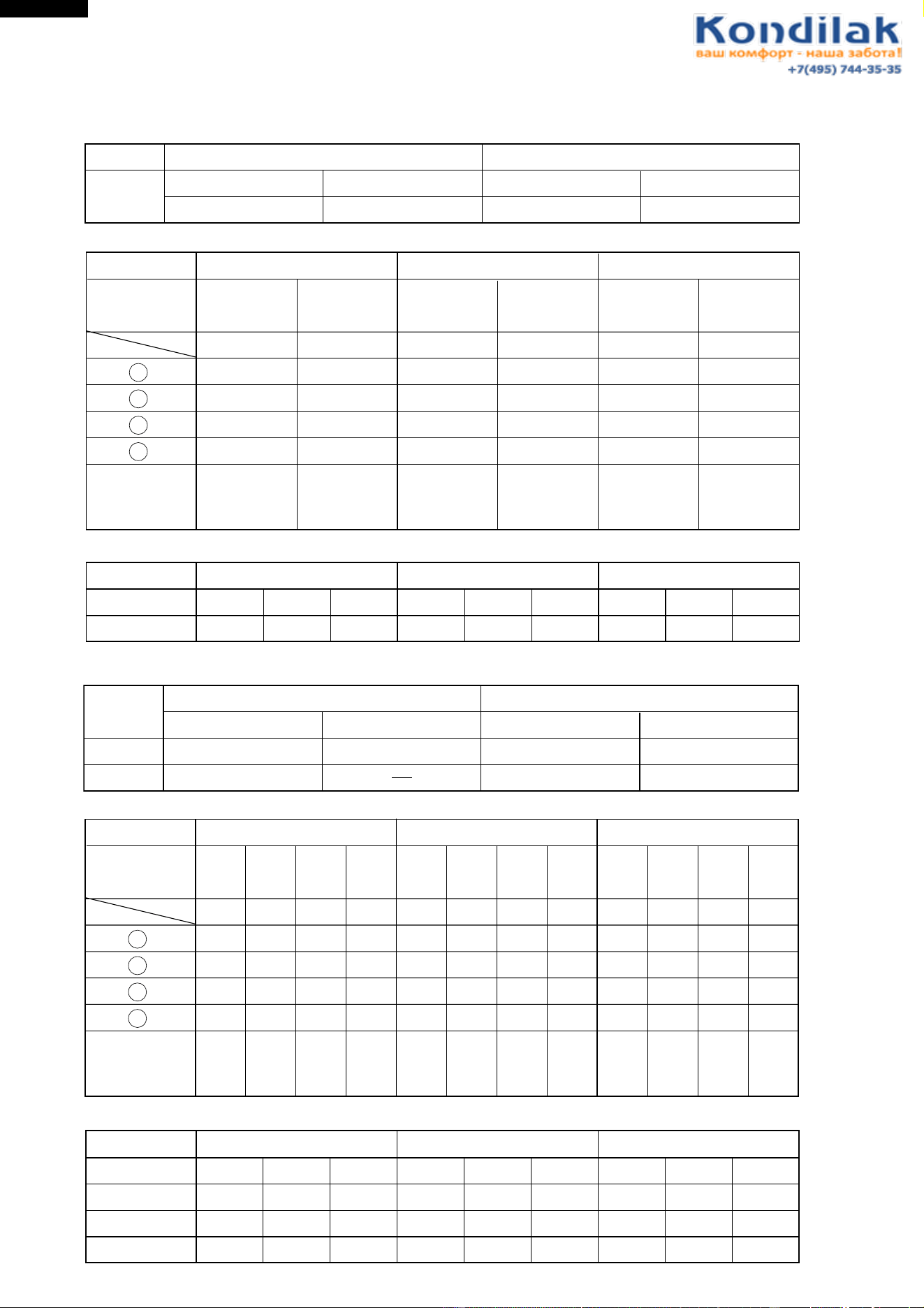
36
AH-X08BE/10BE/13BE
AY-X08BE/10BE/13BE
AY-X08BE-C/10BE-C
AU-X08BE/10BE/13BE
AE-X08BE/10BE/13BE
AE-X08BE-C/10BE-C
Indoor side
Standard conditions:
Dry-bulb Temp. (˚C) Relative Humidity (%)
27Cooling 47
Outdoor side
Dry-bulb Temp. (˚C) Relative Humidity (%)
35 40
AH-X08BE / AH-X10BE / AH-X13BE
Temperature at each part and pressure in 3-way valve
Operation
mode
Model
Cool
(Max.)
1
2
3
4
3-way valve
pressure
(MPaG)
90˚C
40˚C
11˚C
5˚C
0.44
84
97˚C
40˚C
13˚C
10˚C
0.45
101
100˚C
40˚C
13˚C
12˚C
0.46
95
70˚C
41˚C
13˚C
8˚C
0.55
50 settle
73˚C
45˚C
14˚C
11˚C
0.60
50 settle
Cool
Cool
(Max.)
Cool
Cool
(Max.)
Cool
70˚C
42˚C
14˚C
10˚C
0.63
50 settle
No.
Hz
Dimension of Capillary tube
AH-X08BE
AH-X10BE
AH-X13BE
Model
ø2.7
ø2.7
ø2.7
O.D
ø1.4 ø1.5
ø1.6
500
600
I.D L
O.D
I.D L
O.D
I.D L
500
Capillary tube
AH-X10BEAH-X08BE AH-X13BE
Indoor side
Standard conditions:
Dry-bulb Temp. (˚C) Relative Humidity (%)
20Heating
Outdoor side
Dry-bulb Temp. (˚C) Relative Humidity (%)
787
27Cooling 47 35 40
AY-X08BE / AY-X08BE-C / AY-X10BE / AY-X10BE-C / AY-X13BE
Temperature at each part and pressure in 3-way valve
Operation
mode
Cool
(Max.)
Heat
(Max.)
Cool Heat Cool
(Max.)
Heat
(Max.)
Cool Heat Cool
(Max.)
Heat
(Max.)
Cool Heat
Model
1
2
3
4
3-way valve
pressure
(MPaG)
99˚C
42˚C
11˚C
16˚C
0.47 1.79 0.53 1.42 0.49 1.76 0.59 1.28 0.45 1.80 0.64 1.20
65
102˚C
0˚C42˚C
35˚C
3˚C
more
than 67
83˚C
13˚C
12˚C
50 settle
74˚C
2˚C
3˚C
1˚C
50 settle
100˚C
43˚C
14˚C
16˚C
78
96˚C
0˚C
31˚C
3˚C
more
than 85
72˚C
43˚C
15˚C
10˚C
50 settle
59˚C
2˚C
32˚C
2˚C
50 settle
96˚C
42˚C
13˚C
13˚C
98
100˚C
2˚C
35˚C
3˚C
more
than 107
73˚C
41˚C
15˚C
11˚C
50 settle
58˚C
3˚C
31˚C
3˚C
50 settle
No.
Hz
Dimension of Capillary tube
AY-X08BE/X08BE-C AY-X10BE/X10BE-C
AY-X13BE
Model
ø2.7
ø2.7
ø2.7
O.D
ø1.6 ø1.6
ø1.6
150
150
I.D L
O.D
I.D L
O.D
I.D L
150
Capillary tube C
ø2.7
ø2.7
ø2.7
ø1.4 ø1.5
ø1.6
400
400
300
Capillary tube B
ø2.7
ø2.7
ø2.7
ø1.4 ø1.5
ø1.6
500
600
300
Capillary tube A
AY-X10BE/X10BE-CAY-X08BE/X08BE-C AY-X13BE
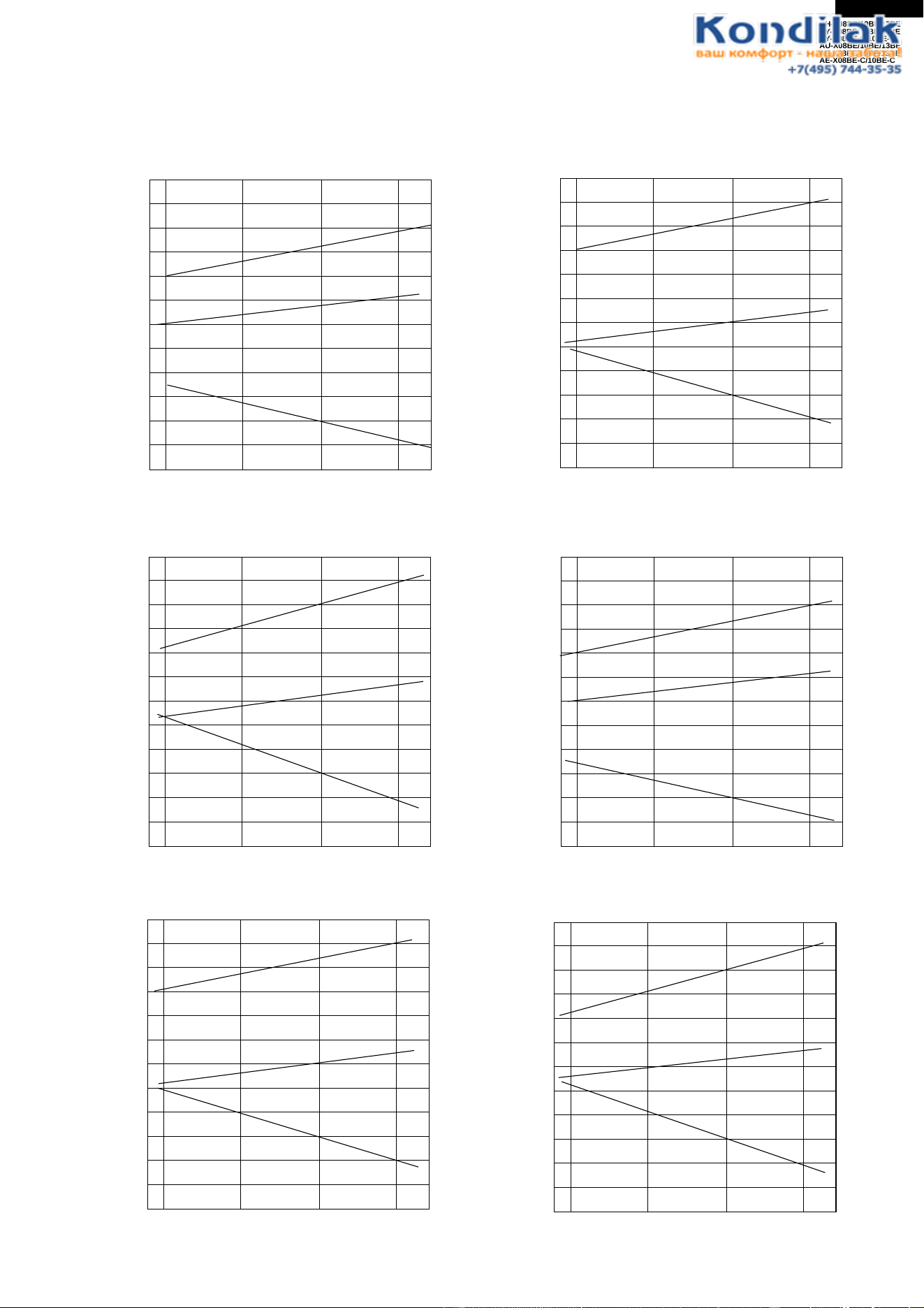
37
AH-X08BE/10BE/13BE
AY-X08BE/10BE/13BE
AY-X08BE-C/10BE-C
AU-X08BE/10BE/13BE
AE-X08BE/10BE/13BE
AE-X08BE-C/10BE-C
25 30 35 40
3.2
3.4
3.6
3.8
4.0
10
12
14
1000
1100
1200
1300
(Running frequency: 79Hz)
Cooling capacity(kW)
Outside air temp.(˚C)
Input(W)
Outlet air temp.(˚C)
25 30 35 40
2.4
2.6
2.8
3.0
3.2
12
14
16
700
800
900
1000
(Running frequency: 62Hz)
Cooling capacity(kW)
Outside air temp.(˚C)
Input(W)
Outlet air temp.(˚C)
25 30 35 40
2.0
2.2
2.4
2.6
10
12
14
600
700
800
900
Cooling capacity(kW)
Outside air temp.(˚C)
Input(W)
Outlet air temp.(˚C)
(Running frequency: 63HZ)
PERFORMANCE CURVES
NOTE: 1) Indoor fan speed: Hi
2) Vertical adjustment louver "45˚", Horizontal adjustment louver "front"
3) Indoor air temp. : Cooling 27˚C, Heating 20˚C
Figure P-1. At Cooling for AH-X08BE
Figure P-2. At Cooling for AH-X10BE
Figure P-3. At Cooling for AH-X13BE Figure P-4. At Cooling for AY-X08BE/X08BE-C
Figure P-5. At Cooling for AY-X10BE/X10BE-C
Figure P-6. At Cooling for AY-X13BE
25 30 35 40
2.0
2.2
2.4
2.6
10
12
14
600
700
800
900
Cooling capacity(kW)
Outside air temp.(˚C)
Input(W)
Outlet air temp.(˚C)
(Running frequency: 49Hz)
25 30 35 40
2.4
2.6
2.8
3.0
3.2
12
14
16
700
800
900
1000
(Running frequency: 77Hz)
Cooling capacity(kW)
Outside air temp.(˚C)
Input(W)
Outlet air temp.(˚C)
25 30 35 40
3.2
3.4
3.6
3.8
4.0
10
12
14
1000
1100
1200
1300
(Running frequency: 76Hz)
Cooling capacity(kW)
Outside air temp.(˚C)
Input(W)
Outlet air temp.(˚C)
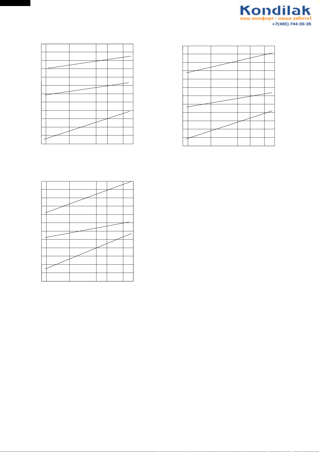
38
AH-X08BE/10BE/13BE
AY-X08BE/10BE/13BE
AY-X08BE-C/10BE-C
AU-X08BE/10BE/13BE
AE-X08BE/10BE/13BE
AE-X08BE-C/10BE-C
-5 0 5 7 10
3.0
3.5
4.0
4.5
5.0
5.5
30
35
40
45
1200
1300
1400
1500
1600
(Running frequency: 95Hz)
Heating capacity(kW)
Outside air temp.(˚C)
Input(W)
Outlet air temp.(˚C)
Figure P-7. At Heating for AY-X08BE/X08BE-C Figure P-8. At Heating for AY-X10BE/X10BE-C
Figure P-9. At Heating for AY-X13BE
-5 0 7510
2.4
2.8
3.2
3.6
35
40
45
700
800
900
1000
(Running frequency: 63Hz)
Heating capacity(kW)
Outside air temp.(˚C)
Input(W)
Outlet air temp.(˚C)
-5 0 5 7 10
2.5
3.0
3.5
4.0
30
35
40
45
800
900
1000
1100
(Running frequency: 74Hz)
Heating capacity(kW)
Outside air temp.(˚C)
Input(W)
Outlet air temp.(˚C)
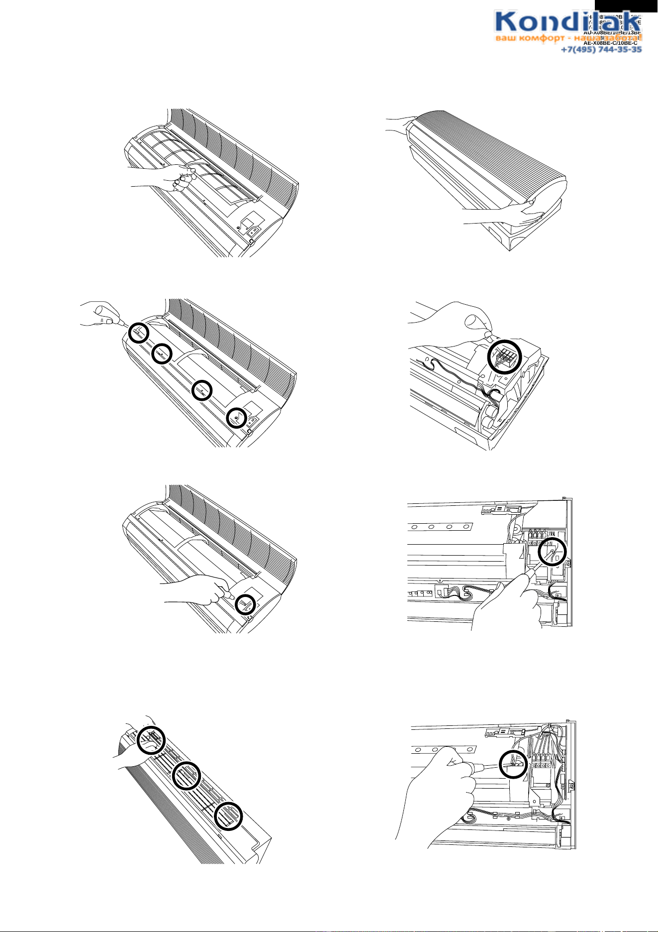
39
AH-X08BE/10BE/13BE
AY-X08BE/10BE/13BE
AY-X08BE-C/10BE-C
AU-X08BE/10BE/13BE
AE-X08BE/10BE/13BE
AE-X08BE-C/10BE-C
DISASSEMBLING PROCEDURE
FOR INDOOR UNIT [AY-X08BE/X08BE-C/X10BE/X10BE-C/X13BE AND AH-X08BE/X10BE/X13BE]
CAUTION : DISCONNECT THE UNIT FROM THE POWER SUPPLY BEFORE ANY SERVICING
1. Open the opne panel, and remove 2 air filters.
2. Remove 4 screws fixing the front panel.
3. Remove the screw fixing the cord clamp.
Note: During reassembly, install the holder after
installing the front panel. This will make it
easier to assemble the front panel.
4. Close the open panel. Pushing the nail of the front
panel.
5. Pull the front panel up.
6. Remove the unit-to-unit wiring from the terminal
board.
7. Remove a screw fixing the control box cover, and
remove it.
8. Remove a screw fixing the ground wire.
Note: During reassembly, take care for the
direction of the lead wire.
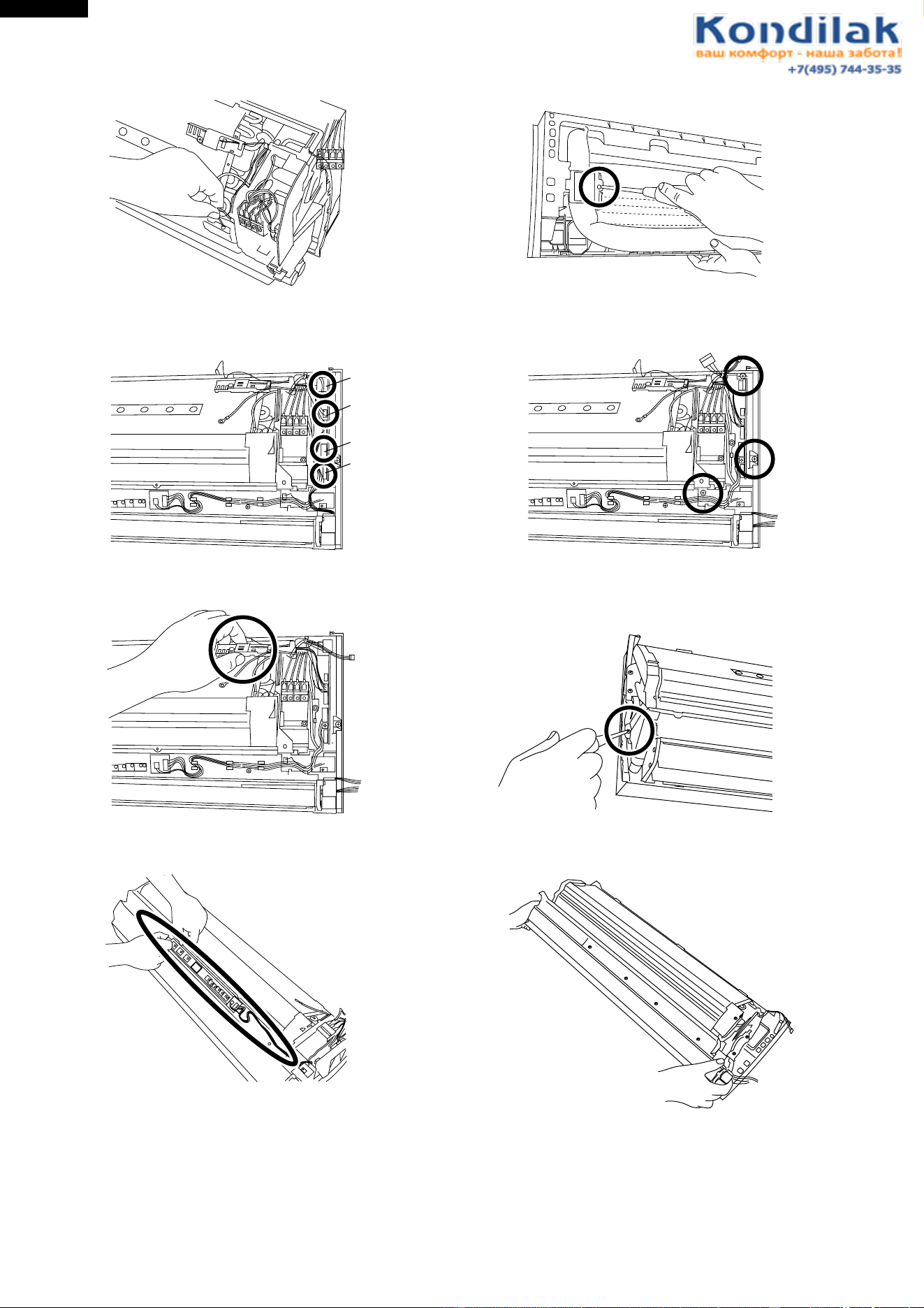
40
AH-X08BE/10BE/13BE
AY-X08BE/10BE/13BE
AY-X08BE-C/10BE-C
AU-X08BE/10BE/13BE
AE-X08BE/10BE/13BE
AE-X08BE-C/10BE-C
9. Remove the thermistor of the evaporator.
10. Remove 4 connectors.
11. Remove the thermistor holder from the evaporator.
12. Remove the display from the drain pan.
13. Remove the screw fixing the pipe holder.
14. Remove 3 screws fixing the control box, and remove
the control box.
15. Remove a screw fixing the drain pan.
16. Pull drain pan toward you.
CN1
CN6
CN3
CN2
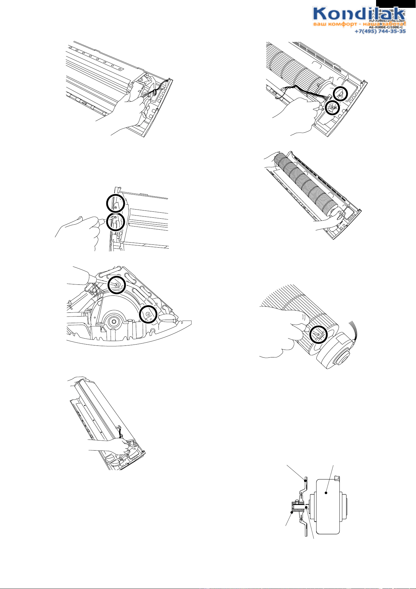
41
AH-X08BE/10BE/13BE
AY-X08BE/10BE/13BE
AY-X08BE-C/10BE-C
AU-X08BE/10BE/13BE
AE-X08BE/10BE/13BE
AE-X08BE-C/10BE-C
17. Remove the drain cover from the evaporator.
Note: During reassembly, verify that the dew on
the pipe is led to the drain pan.
18. Remove 4 screws fixing the evaporator.
19. Remove the evaporator from the cabinet.
20. Remove 2 screws fixing the motor cover, and pull up
the fan.
21. Loose a screw fixing fan.
[Cautionary points for assembling the fan]
a. When inserting the motor shaft into the metal fan
boss, take care to prevent injuring the inner surface of
the metal fan boss.
b. Before fastening the motor shaft and fan, insert the
motor shaft into contact with the bottom of the metal
fan boss.
Fan motor
Motor shaft
Fan boss
Cross flow fan
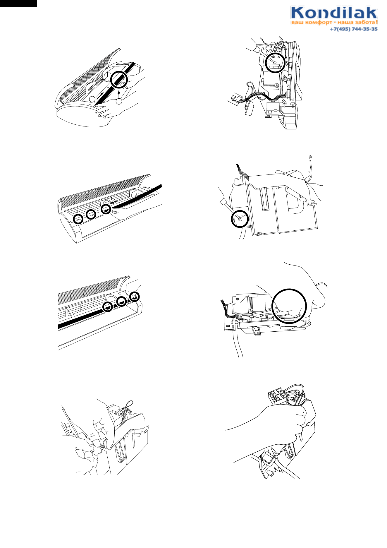
42
AH-X08BE/10BE/13BE
AY-X08BE/10BE/13BE
AY-X08BE-C/10BE-C
AU-X08BE/10BE/13BE
AE-X08BE/10BE/13BE
AE-X08BE-C/10BE-C
How to remove the display cover
1. Push the center of display cover from the back.
2. Slide the display cover to the right.
How to assemble the display cover
1. Slide the left end of the display cover through 3 hooks
on the front panel along the guide from the center of
the front panel.
2. After the left half is inseted completely, press the
display cover and snap in the 3 hooks on the right.
How to remove the control box
2. Remove the screw fixing the terminal board.
1
2
1. Remove the photo detector unit.
(Press and spread the upper hook, and the photo
detector unit will be ready for removal.)
3. Remove a screw fixing the cord holder.
4. Remove 2 screws fixing the board (transformer).
5. Pull the board.
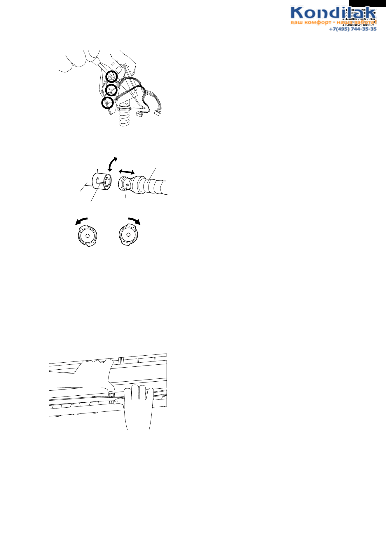
43
AH-X08BE/10BE/13BE
AY-X08BE/10BE/13BE
AY-X08BE-C/10BE-C
AU-X08BE/10BE/13BE
AE-X08BE/10BE/13BE
AE-X08BE-C/10BE-C
Drain pan and related
1. Remove 3 screws fixing motors.
2. Turn the cap area of the drain hose counterclockwise,
and remove it from the drain pan.
During installation, turn the drain hose to the state of
the “engagement position”.
After reinstallation, verify that it is securely fastened.
How to remove the horizontal louver
Slightly pull down the hinge area, defelect thge louver,
and unhook it from the hinge. Remove the shaft from
each of the left and right sides.
Drain pan
Drain Hose
Groove
Projection
To disconned To reconnect
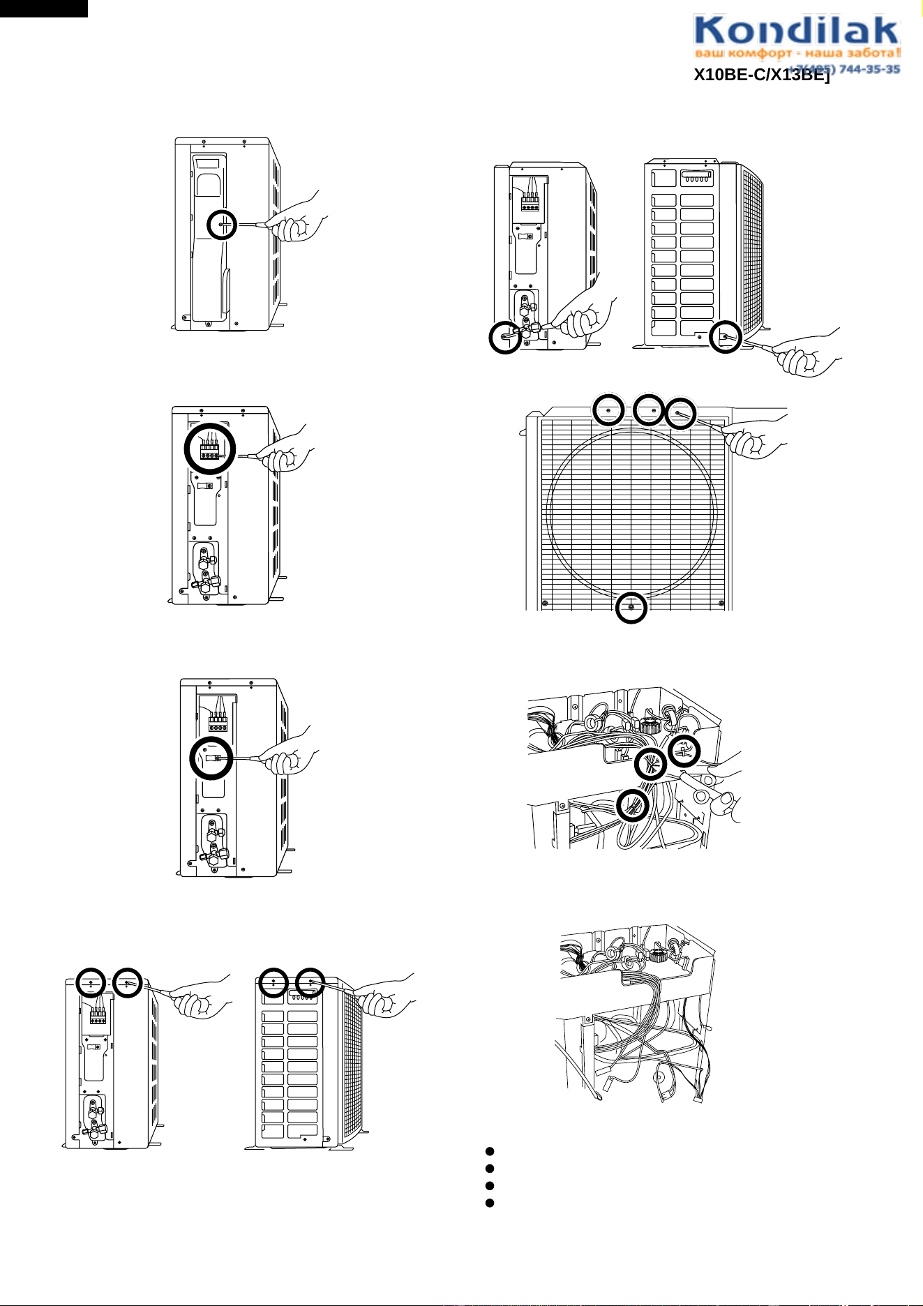
44
AH-X08BE/10BE/13BE
AY-X08BE/10BE/13BE
AY-X08BE-C/10BE-C
AU-X08BE/10BE/13BE
AE-X08BE/10BE/13BE
AE-X08BE-C/10BE-C
FOR OUTDOOR UNIT [AU-X08BE/X010BE/X13BE, AE-X08BE/X08BE-C/X010BE/X10BE-C/X13BE]
CAUTION : DISCONNECT THE UNIT FROM THE POWER SUPPLY BEFORE ANY SERVICING
1. Loose a screw fixing the side cover.
Right side view Left side view
Right side view Left side view
Front view
2. Loose the unit to unit cord.
3. Loose a screw fixing the cord clamp.
4. Loose 4 screws fixing the top panel.
5. Loose 6 screws fixing the front panel.
6. Cut 3 nylon bands.
7. Disconnect following connectors and each wire.
Choke coil(two terminal)
Fan motor
Thermistor
Reverse valve
(AE-X08BE/X08BE-C/10BE/X10BE-C/13BE)
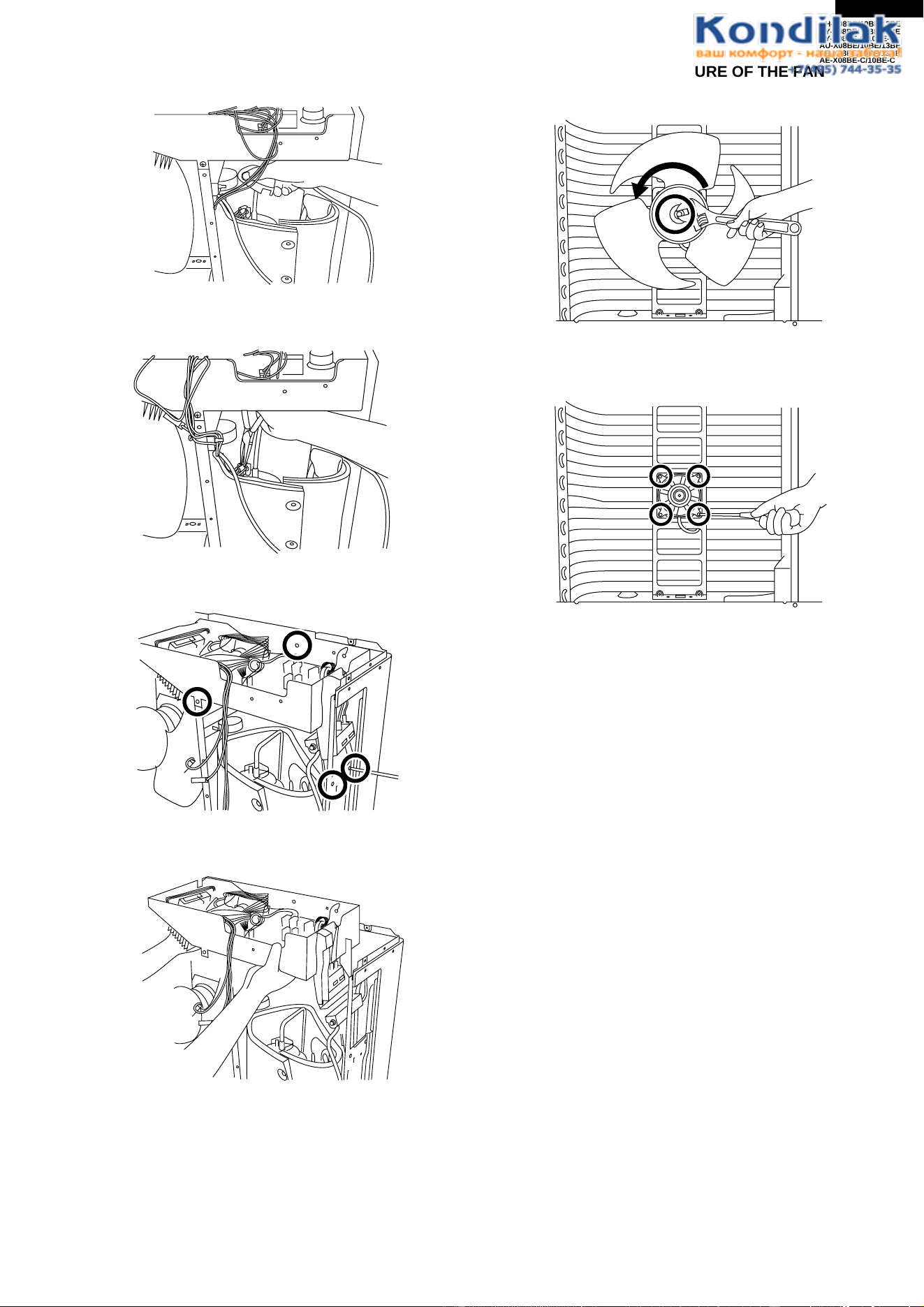
45
AH-X08BE/10BE/13BE
AY-X08BE/10BE/13BE
AY-X08BE-C/10BE-C
AU-X08BE/10BE/13BE
AE-X08BE/10BE/13BE
AE-X08BE-C/10BE-C
8. Remove the terminal cover of compressor.
9. Remove 3 terminals of compressor..
10. Loose 4 screws fixing the control box.
11. Take out the control box.
DISASSEMBLING PROCEDURE OF THE FAN
1. Loose the fan nut and fan can take out.
2. Fan motor is secured by 4 screws.
Loose
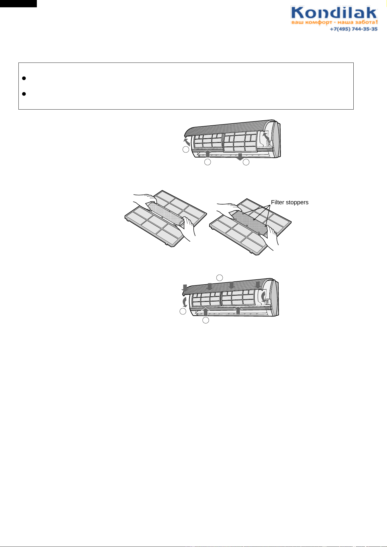
46
AH-X08BE/10BE/13BE
AY-X08BE/10BE/13BE
AY-X08BE-C/10BE-C
AU-X08BE/10BE/13BE
AE-X08BE/10BE/13BE
AE-X08BE-C/10BE-C
OPTION
HOW TO REPLACE THE AIR PURIFYING FILTER (AZ-F900B; Electrostatic Type (2-sheet package))
Precautions
The filters are sealed in a plastic bag to keep thier dust collection effect. Do not open the bag until using the
filters. (Otherwise the filters’ life may get shorter.)
Do not expose the filters to direct sunlight.
(Otherwise they may deteriorate.)
1. REMOVE THE AIR FILTERS.
1) Open the front panel
2) Push the air filter up slightly to unhook them.
2. CHECK THE AIR PURIFYING FILTERS.
1) Take of the old air purifying filters from the air filters. Snap out in the arrow marked direction.
2) Set the new air purifying filters with filter stopperts located on the air filters.
3. REINSTALL THE AIR FILTERS
1) Reinstall the air filters in the original positions.
2) Close the front panel.
3) Push the center part of the panel firmly to lock it in place.
REPLACEMENT INTERVALS GUIDELINE
Replace the air purifying filters at the intervals of 3-6 months.
The dirty filters are not washable for reuse.
The filters are available at your nearest dealer.
1
2
3
3
1
2
;;;;;;;;;;;;;;;;;;;
;;;;;;;;;;;;;;;;;;;
;;;;;;;;;;;;;;;;;;;
;;;;;;;;;;;;;;;;;;;
;;;;;;;;;;;;;;;;;;;
;;;;;;;;;;;;;;;;;;;
;;;;;;;;;;;;;;;;;;;
;;;;;;;;;;;;;;;;;;;
;;;;;;;;;;;;;;;;;;;
;;;;;;;;;;;;;;;;;;;
;;;;;;;;;;;;;;;;;;;
;;;;;;;;;;;;;;;;;;;
;;;;;;;;;;;;;;;;;;;
;;;;;;;;;;;;;;;;;;
;;;;;;;;;;;;;;;;;;
;;;;;;;;;;;;;;;;;;
;;;;;;;;;;;;;;;;;;
;;;;;;;;;;;;;;;;;;
;;;;;;;;;;;;;;;;;;
;;;;;;;;;;;;;;;;;;
;;;;;;;;;;;;;;;;;;
;;;;;;;;;;;;;;;;;;
;;;;;;;;;;;;;;;;;;
;;;;;;;;;;;;;;;;;;
Filter stoppers
47
AH-X08BE/10BE/13BE
AY-X08BE/10BE/13BE
AY-X08BE-C/10BE-C
AU-X08BE/10BE/13BE
AE-X08BE/10BE/13BE
AE-X08BE-C/10BE-C
REF. NO. PART NO. DESCRIPTION Q'TY CODE
REPLACEMENT PARTS LIST [AH-X08BE/10BE/13BE,AY-X08BE/X08BE-C/10BE/X10BE-C/13BE]
CABINET AND UNIT PARTS
1- 1 CMOT-A389JBKZ Fan motor sub assembly 1 BG
1- 2 PGUMSA046JBE0 Damper rubber 1 AD
1- 3 CHLD-A067JBK0 Bearing assembly 1 AL
1- 4 DCHS-A399JBKZ Cabinet sub assembly
[AY-X08BE/X08BE-C, AH-X08BE/X10BE]
1BD
1- 4 DCHS-A401JBKZ Cabinet sub assembly [AY-X10BE/X10BE-C/13BE, AH-X13BE] 1 BC
1- 5 NFANCA089JBEZ Cross flow fan 1 BD
1- 6 DSRA-A234JBKZ Drain pan sub assembly 1 BB
1- 7 CMOTLA901JBEZ Fan motor 1 BG
1- 8 MJNTPA082JBFA Louver link 2 AC
1- 9 MLOV-A299JBFA Vertical louver 12 AC
1-10 MLOV-A297JBFA Horizontal louver A 1 AK
1-11 MLOV-A298JBFA Horizontal louver B 1 AK
1-12 QW-VZC406JBE0 Lead wire (for Fan motor) 1 AK
1-13 LHLD-A197JBFP Louver holder 2 AX
1-14 NBRG-A026JBFA Louver bushing 2 AB
1-15 LHLD-A476JBFZ Display cover 1 AK
1-16 PHOS-A025JBE0 Drain hose 1 AL
1-17 PPACGA010JBE0 O ring 1 AB
1-18 PGID-A097JBFZ Drain cover 2 AF
1-19 RMOT-A061JBE0 Louver motor 2 AS
1-20 PGUMMA110JBE0 Drain plug 1 AD
1-21 CWAK-C101JBKZ Front panel assembly 1 BL
1-22 PPLT-A212JBFZ Side cover R 1 AL
1-23 PPLT-A213JBFZ Side cover L 1 AL
1-24 PCOV-A615JBRA Display cover 1 BC
1-25 PFILMA145JBEA Air filter 2 AL
1-26 DHLD-A010JBKZ Tube holder assembly 1 AK
1-27 HPNL-A514JBFA Open panel 1 AQ
1-28 TSPC-D601JBRA Name label [AH-X08BE] 1 AF
1-28 TSPC-D599JBRA Name label [AH-X10BE] 1 AF
1-28 TSPC-D600JBRA Name label [AH-X13BE] 1 AE
1-28 TSPC-D598JBRA Name label [AY-X08BE] 1 AC
1-28 TSPC-E063JBRA Name label [AH-X08BE-C] 1 AC
1-28 TSPC-D588JBRA Name label [AY-X10BE] 1 AC
1-28 TSPC-E064JBRA Name label [AY-X10BE-C] 1 AC
1-28 TSPC-D591JBRA Name label [AY-X13BE] 1 AC
1-29 PFPFPB901JBEZ Cabinet insulator [AY-X08BE/X08BE-C, AH-X08BE/X10BE) 1 AH
1-30 QW-VZE013JBZZ Lead wire(upper) 1 AG
1-31 GWAK-A257JBFA Front panel 1 AX
1-32 PCOV-A614JBFZ Drain cover 1 AG
1-33 TLABCB374JBRZ Wiring diagram 1 AC
1-34 QW-VZD893JBZZ Lead wire (Lower) 1 AG
1-35 LHLD-A303JBFA Tube cover 1 AD
1-36 PSEL-C125JBEZ Panel insulator 1 AF
1-37 HDEC-B108JBEZ Sheet 2 AF
1-38 HDEC-B112JBEZ Sheet 1 AN
1-39 PSEL-C055JBEZ Evaporator seal [AY-X10BE/X10BE-C/X13BE, AH-X13BE] 1 AC
1-40 PSHE-A126JBE0 Evaporator seal 1 AG
1-41 LSPR-A007JBE0 Seet spring 2 AD
1-42 PSEL-C136JBEZ Insulator [AY-X10BE/X10BE-C/X13BE, AH-X13BE] 1 AC
1-43 PFPFPB962JBEZ Insulator 1 AC
1-44 PFPFPB967JBEZ Sidecover insulator 1 AC
CONTROL BOX
2- 1 RTHM-A300JBE0 Thermistor 1 AP
2- 2 PBOX-A342JBFZ Control box 1 AQ
2- 3 PBOX-A341JBFZ Terminal cover 1 AH
2- 4 LHLD-A500JBFZ Thermistor holder 1 AC
2- 5 PCOV-A300JBF0 Thermo holder cover 1 AB
2- 6 HPNLCA776JBFA Control box cover 1 AG
2- 7 HPNLCA777JBEA Control panel 1 AD
2- 8 PCOV-A618JBFA LED holder 1 AE
2- 9 PCOV-A619JBFA LED holder B 1 AE
2-10 DPWBFA205JBKZ Control board unit [AH-X08BE] 1 BR
2-10 DPWBFA200JBKZ Control board unit [AH-X10BE] 1 BR
2-10 DPWBFA201JBKZ Control board unit [AH-X13BE] 1 BR
2-10 DPWBFA199JBKZ Control board unit [AY-X08BE/X08BE-C] 1 BR
2-10 DPWBFA196JBKZ Control board unit [AY-X10BE/X10BE-C] 1 BR
2-10 DPWBFA197JBKZ Control board unit [AY-X13BE] 1 BR
2-11 QACC-A158JBE0 Power supply cord 1 AT
2-12 QTANZA002JBZZ Terminal board (3pin) 1 AN
2-13 QTANZA001JBZZ Terminal board (4pin) 1 AQ
2-14 PCOV-A609JBWZ Control box cover 1 AC
2-15 RIC--A025BDE0 IC (IC4, IC5) 2 AE
48
AH-X08BE/10BE/13BE
AY-X08BE/10BE/13BE
AY-X08BE-C/10BE-C
AU-X08BE/10BE/13BE
AE-X08BE/10BE/13BE
AE-X08BE-C/10BE-C
REF. NO. PART NO. DESCRIPTION Q'TY CODE
HOW TO ORDER REPLACEMENT PARTS
To have your order filled prompty and correctly, please furnish the following information.
1. MODEL NUMBER 2. REF. NO. 3. PART NO. 4. DESCRIPTION
2-16 VHPGL6ZS27+-6 LED (LED102) 1 AG
2-17 VHPSL326422-6 LED (LED121) 1 AP
2-18 PCOV-A611JBWZ Control box cover 1 AF
2-19 PCOV-A610JBWZ Terminal cover 1 AE
2-20 RRMCUA001JBZZ Photo detector unit (IC201) 1 AK
2-21 QFS-GA040JBZZ Fuse 3A 250V (WPE1) 1 AE
2-22 VHIKID65783-1 IC (IC6) 1 AK
2-23 RIC--A022BDE0 IC (IC3) 1 AE
2-24 VHIBR24C01A-6 IC (IC8) 1 AF
2-25 RH-TZA098JBE0 Transistor (Q1, Q2) 2 AB
2-26 RH-VZA020JBE0 Varistor (CNR1) 1 AE
2-27 RH-VXA002JBZZ Varistor (NR1) 1 AF
2-28 RH-IZA149JBE0 IC (IC2) 1 AE
2-29 VHPGL6ZE27+-6 LED (LED103 - 111) 9 AG
2-30 RRLYDA010JBZZ Relay (RY1) 1 AN
2-31 RTRN-A287JBZZ Transformer (TRANS 1) 1 AT
2-32 VHPGL6ZR27+-6 LED (LED101) 1 AF
2-33 VHRPC817X7/1B Photo coupler (PC1) 1 AD
2-34 VHRPC853H//-6 Photo coupler (PC2) 1 AG
2-35 VHRS201D01/-6 Solid state relay (SSR1) 1 AK
2-36 VHD1SR139-6-1 Diode (D7-D9) 3 AB
2-37 VHD1SR35-4A-1 Diode (D1-D5) 5 AC
2-38 VHEHZ24-2//-1 Zenner diode (ZD1) 1 AB
CYCLE PARTS
3- 1 CPIPCA678JBKZ Tube assembly [AH-X08BE/10BE, AY-X08BE/X08BE-C] 1 BG
3- 1 CPIPCA679JBKZ Tube assembly [AH-X13BE, AY-X13BE] 1 BH
3- 1 CPIPCA690JBKZ Tube assembly [AY-X10BE/X10BE-C] 1 BH
3- 2 PSEN-A004JBK0 Flare nut assembly (1/4") 1 AE
3- 3 PSEN-A005JBK0 Flare nut assembly (3/8") 1 AG
3- 3 PSEN-A016JBK0 Flare nut assembly (1/2") 1 AR
3- 4 PVLV-0341JBE0 Flare union (1/4") 1 AG
3- 5 PVLV-0342JBE0 Flare union (3/8") 1 AH
3- 5 PVLV-0406JBE0 Flare union (1/2") 1 AK
3- 6 DEVA-A128JBKZ Evaporator sub assembly [AY-X10BE/X10BE-C] 1 BT
3- 6 DEVA-A123JBKZ Evaporator sub assembly [AH-X08BE] 1 BR
3- 6 DEVA-A122JBKZ Evaporator sub assembly [AH-X13BE/AY-X13BE] 1 BT
3- 6 DEVA-A121JBKZ Evaporator sub assembly [AH-X10BE/AY-X08BE/X08BE-C] 1 BS
ACCESSORY PARTS
4- 1 CRMC-A529JBEZ Remote control [AH-X08BE/X10BE/X13BE] 1 BD
4- 1 CRMC-A528JBEZ Remote control [AY-X08BE/X08BE-C/X10BE/X10BE-C/X13BE] 1 BB
4- 2 UBATUA027JBE0 Battery pack 1 AE
4- 3 LHLD-A477JBFA
Cord holder(for covering the terminal board of indoor unit)
1AE
4- 4 XTTSD40P16000 Tapping screw (for fixing the cord holder) 1 AA
4- 5 LX-NZA207JBEZ Special nut (for fixing long screw steadily) 9 AE
4- 6 LPFT-A029JBF0 Drain joint [AY-X08BE/X08BE-C/X10BE/X10BE-C/X13BE] 1 AD
4- 7 PPLTNA058JBWZ Mounting angle 1 AS
4- 8 XTTSD45P30000 Long screw 8 AA
4- 9 TINSEA262JBRZ Operation manual 1 AM
4-10 TINS-A664JBRZ Installation manual 1 AE
4-11 TINS-A665JBRZ Installation manual 1 AE
4-12 LX-BZA106JBE0 Special screw (for hanging remote controller) 1 AE
SCREWS
5- 1 LX-BZA075JBE0 Special screw (for earth) 1 AA
PACKING PARTS
6- 1 CPADBA038JBKZ Packing pad assembly 2 AK
6- 2 SPAKCA745JBEZ Packing case [AH-X08BE] 1 AR
6- 2 SPAKCA743JBEZ Packing case [AH-X10BE] 1 AR
6- 2 SPAKCA744JBEZ Packing case [AH-X13BE] 1 AR
6- 2 SPAKCA742JBEZ Packing case [AY-X08BE] 1 AR
6- 2 SPAKCA972JBEZ Packing case [AY-X08BE-C] 1 AQ
6- 2 SPAKCA740JBEZ Packing case [AY-X10BE] 1 AR
6- 2 SPAKCA971JBEZ Packing case [AY-X10BE-C] 1 AR
6- 2 SPAKCA741JBEZ Packing case [AY-X13BE] 1 AR
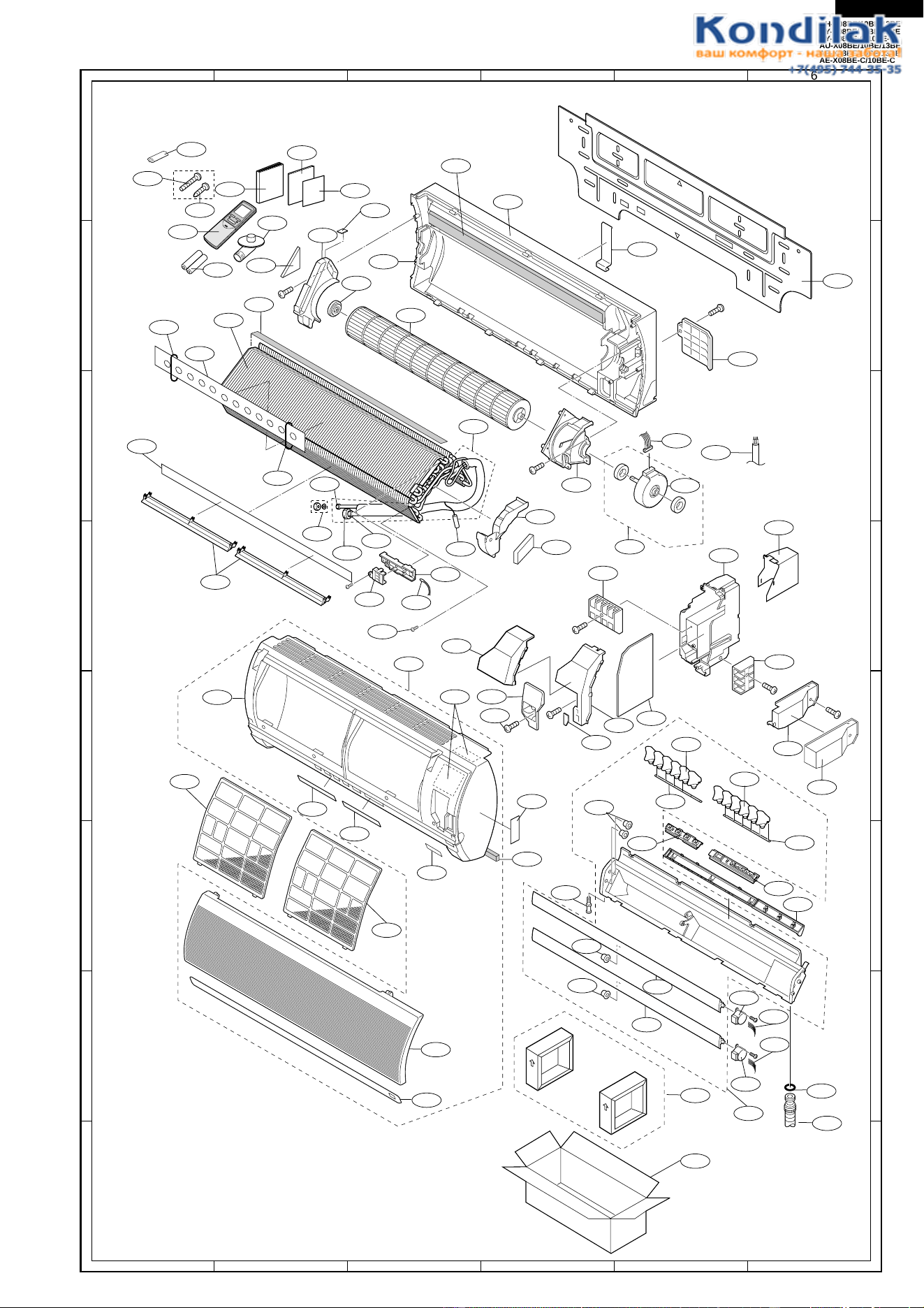
49
AH-X08BE/10BE/13BE
AY-X08BE/10BE/13BE
AY-X08BE-C/10BE-C
AU-X08BE/10BE/13BE
AE-X08BE/10BE/13BE
AE-X08BE-C/10BE-C
A
B
C
D
E
F
G
H
A
123456
123456
B
C
D
E
F
G
H
1-4
4-1
4-2
4-6
1-35
1-23
1-44
3-6
1-39
1-41
1-40
1-42
1-41
1-18
1-5
1-4
1-29
1-3
1-26
4-7
2-11
1-22
1-1
1-12
1-32
1-2
2-1
3-1
2-4
2-5
3-2
3-5
3-3
3-4
2-1
5-1
1-7
2-13
2-2
2-18
2-14
1-21
4-3
4-4
2-6
2-7
1-16
1-30
1-19
1-19
1-13
1-20
1-14
1-13
1-11
1-17
1-10
1-6
1-27
6-1
6-2
1-24
1-25
1-31
1-37
1-38
1-28
1-33
1-36
1-37
1-25
2-3
2-19
2-12
2-10
4-9
4-11
4-8
4-12
4-5
4-10
4-43
2-9
1-15
1-34
1-8
1-8
2-8
1-9
1-9
INDOOR UNIT FOR AY-X08BE/08BE-C/X10BE/10BE-C/X13BE AND
AH-X08BEX10BE/X13BE
50
AH-X08BE/10BE/13BE
AY-X08BE/10BE/13BE
AY-X08BE-C/10BE-C
AU-X08BE/10BE/13BE
AE-X08BE/10BE/13BE
AE-X08BE-C/10BE-C
REPLACEMENT PARTS LIST [AU-X08BE/X10BE/X13BE,AE-X08BE/X08BE-C/X10BE/X10BE-C/X13BE]
REF. NO. PART NO. DESCRIPTION Q'TY CODE
CONTROL BOX PARTS
1- 1 CMOTLA902JBEZ Fan motor
[AE-X08BE/X08BE-C/X10BE/X10BE-C, AU-X08BE/X10BE]
1BK
1- 1 CMOTLA903JBEZ Fan motor [AE-X13BE, AU-X13BE] 1 BL
1- 2 RTRN-A256JBE0 Current transfoemer CT1 1 AG
1- 3 RFIL-A100JBZZ Coil [AE-X08BE/X10BE, AU-X08BE/X10BE] 2 AY
1- 3 RFIL-A102JBZZ Coil [AE-X13BE, AU-X13BE] 2 AV
1- 3a RFIL-A104JBZZ Coil [AE-X08BE-C/X10BE-C, AU-X08BE/X10BE] 1 AR
1- 3a RFIL-A106JBZZ Coil [AE-X13BE, AU-X13BE] 1 AV
1- 3b RFIL-A105JBZZ Coil
[AE-X08BE-C/X10BE-C,AU-X08BE/X10BE,AE-X13BE,AU-X13BE]
1AR
1- 4 DPWBFA195JBKZ Electric control board [AE-X08BE/X10BE] 1 BS
1- 4 DPWBFA282JBKZ Electric control board [AE-X08BE-C/X10BE-C] 1 BP
1- 4 DPWBFA198JBKZ Electric control board [AE-X13BE] 1 BG
1- 4 DPWBFA240JBKZ Electric control board [AE-X13BE] 1 BQ
1- 4 DPWBFA202JBKZ Electric control board [AU-X08BE/X10BE] 1 BS
1- 4 DPWBFA239JBKZ Electric control board [AU-X08BE/X10BE] 1 BP
1- 4 DPWBFA203JBKZ Electric control board [AU-X13BE] 1 BS
1- 5 QTANZA001JBZZ Terminal board (4P) 1 AQ
1- 6 RIC--A022BDE0
Integrated circuit IC2 [AE-X08BE/X08BE-C/X10BE/X10BE-C,AU-X08BE/X10BE]
1AE
1- 6 VHIK7818API-1
Integrated circuit IC2 [AE-X13BE,AU-X13BE]
1AF
1- 7 VSKRC245M//-3 Transistor Q3 1 AC
1- 8 VHRPC817X7/1B Photo coupler PC1 1 AE
1- 8 VHRPC817X7/1B Photo coupler PC3, PC4 [AE-X13BE, AU-X13BE] 2 AE
1- 9 VHRPC853H//-6 Photo coupler PC2 1 AG
1-10 RC-EZA250JBZZ Capacitor
[AE-X08BE/X08BE-C/10BE/X10BE-C, AU-X08BE/10BE]
1AC
1-10 RC-EZA249JBZZ Capacitor
[AE-X13BE, AU-X13BE]
1BP
1-11 RH-DZA117JBE0 Diode bridge
[AE-X08BE/X08BE-C/10BE/X10BE-C, AU-X08BE/10BE]
1AM
1-11 RH-DZA087JBE0 Diode bridge [AE-X13BE, AU-X13BE] 1 AQ
1-12 RH-HZ0011JBE0 PTC thermistor 1 AN
1-13 RH-TZA145JBE0
Power transistor module(IPM)[AE-X08BE/X08BE-C/10BE/X10BE-C,AU-X08BE/10BE]
1BU
1-13 VHITM38++++-1
Power transistor module(IPM)[AE-X13BE, AU-X13BE]
1BY
1-14 PDAI-A126JBWZ Terminal plate 1 AE
1-15 VHITM-05C//-6 Active filter
[AE-X08BE/X08BE-C/X10BE/X10BE-C, AU-X08BE/X10BE]
1BP
1-15 RH-TXA003JBZZ Active filter [AE-X13BE, AU-X13BE] 1 BS
1-16 RTHM-A022JBE0 Compressor thermistor 1 AN
1-17 RH-HXA010JBZZ Thermistor 1 AX
1-18 RTRN-A199JBE0 Choke coil
[AE-X08BE/X08BE-C/X10BE/X10BE-C, AU-X08BE/X10BE]
1BE
1-18 RTRN-A286JBEZ Choke coil [AE-X13BE, AU-X13BE] 1 BF
1-19 PBOX-A343JBWZ Control box 1 AR
1-20 LBND-A042JBE0 Wire fixing band 4 AC
1-21 PSPA-A151JBZZ Spacer 5 AE
1-22 LHLD-A479JBFZ Heat sink holder 1 AE
1-23 PRDAFA140JBEZ
Heat sink for powertransistor module[AE-X08BE/X08BE-C/10BE/X10BE-C,AU-X08BE/10BE]
1AX
1-23 PRDAFA142JBEZ
Heat sink for powertransistor module [AE-X13BE, AU-X13BE]
1AX
1-24 QW-VZD962JBZZ Lead wire (CN14-QM1) [AE-X13BE, AU-X13BE] 1 AE
1-25 PSHE-A190JBEZ Protect sheet 1 AL
1-26 PSEL-C061JBEZ Insulator 1 AE
1-27 PSPA-A144JBE0 Spacer 2 AC
1-28 RFIL-A064JBE0 Ferrite core 4 AF
1-29 QW-VZD961JBZZ Lead wire (CN13-AF1) [AE-X13BE, AU-X13BE] 1 AG
1-30 QW-VZD871JBZZ Lead wire (L1+) 1 AG
1-30-1 QW-VZE041JBZZ Lead wire (L1-) 1 AE
1-31 QW-VZD857JBZZ Lead wire (Earth) 1 AC
1-32 QW-VZD868JBZZ Lead wire (MRY1 - DB1) 1 AG
1-33 QW-VZD861JBZZ Lead wire (MRY1 - PTC) 1 AF
1-34 QW-VZD958JBZZ Lead wire (DB1+-AF(I+)) 1 AK
1-35 QW-VZD866JBZZ Lead wire (T3 - TB2) 1 AF
1-36 QW-VZD873JBZZ Lead wire (T10 - IPM(-)) 1 AF
1-37 QW-VZD867JBZZ Lead wire (T5 - DB1)) 1 AG
1-38 QW-VZD864JBZZ Lead wire (T2 - TBN) 1 AF
1-39 QW-VZD865JBZZ Lead wire (T1 - TB1) 1 AF
1-40 QW-VZD859JBZZ Lead wire (C8(+) - T7) 1 AE
1-41 QW-VZD870JBZZ
Lead wire (C8(+) - AF(0+))[AE-X08BE/X08BE-C/X10BE/X10BE-C, AU-X08BE/X10BE]
1AG
1-42 QW-VZD960JBZZ Lead wire (C8-AF) [AE-X13BE, AU-X13BE] 1 AL
1-43 QW-VZD869JBZZ
Lead wire (C8(-) - AF(0-))[AE-X08BE/X08BE-C/X10BE/X10BE-C, AU-X08BE/X10BE]
1AF
1-44 QW-VZD860JBZZ Lead wire (C8(-) - T8) 1 AE
1-45 QW-VZD872JBZZ Lead wire (T9 - IPM(+)) 1 AE
1-46 QW-IZA007JBZZ Lead wire (Compressor wire) [AE-X08BE/X10BE] 1 AP
1-46 QW-IZA017JBZZ Lead wire (Compressor wire) [AE-X08BE/X10BE] 1 AP
1-46 QW-IZA019JBZZ Lead wire (Compressor wire) [AE-X13BE, AU-X13BE] 1 AP
1-46 QW-IZA022JBZZ Lead wire (Compressor wire) [AE-X10BE-C] 1 AM
1-46 QW-IZA023JBZZ Lead wire (Compressor wire) [AE-X08BE-C] 1 AS
1-47 QW-VZD420JBE0 Lead wire (AF lead wire 4P)
[AE-X08BE/X08BE-C/X10BE/X10BE-C]
1AE
1-48 RH-IXA726JBZZ Microcomputer IC1 1 AW
1-49 RH-IZA140JBE0 Integrated circuit IC3 1 AE
1-50 RH-TZA098JBE0 Transistor Q1, Q2, Q4 3 AB
1-51 RH-VZA020JBE0 Varistor CNR1, CNR2 2 AB
51
AH-X08BE/10BE/13BE
AY-X08BE/10BE/13BE
AY-X08BE-C/10BE-C
AU-X08BE/10BE/13BE
AE-X08BE/10BE/13BE
AE-X08BE-C/10BE-C
1-52 RH-VXA002JBZZ Varistor NR1, NR2 2 AD
1-53 RH-VZA042JBE0 Surge absorber SA1 1 AH
1-54 LBNDKA098JBWZ
Capacitor clamp [AE-X08BE/X08BE-C/10BE/X10BE-C, AU-X08BE/10BE]
1AP
1-54 LBNDKA099JBWZ
Capacitor clamp [AE-X13BE, AU-X13BE]
1AS
1-55 PSEL-C122JBEZ Insulator 1 AC
1-56 PSEL-C123JBEZ Insulator 1 AC
1-57 PSEL-C124JBEZ Insulator 1 AC
CABINET AND UNIT PARTS
2- 1 LANGKA124JBPZ Fan motor angle 1 AR
2- 2 LANGKA127JBPZ
Fan motor angle sub [AE-X08BE/X08BE-C/X10BE/X10BE-C, AU-X13BE]
1AE
2- 2 LANGKA128JBPZ
Fan motor angle sub [AU-X08BE/X10BE]
1AG
2- 2 LANGKA123JBPZ
Fan motor angle sub [AE-X13BE]
1AE
2- 3 GCAB-A196JBTA Rear cabinet 1 BD
2- 3 GCAB-A203JBTA Rear cabinet [AU-X13BE] 1 BC
2- 4 LHLD-0261JBM0 Cord holder 1 AB
2- 5 PFPFPB911JBEZ Motor angle cushion 1 AC
2- 6 GCAB-A195JBTA Front panel 1 BC
2- 7 GGADFA037JBFA Fan guard 1 AT
2- 8 PSEL-C045JBEZ Motor angle cushion 1 AB
2- 9 PSEL-C048JBEZ F panel insulator 1 AC
2-10 PSEL-C049JBEZ F panel insulator 1 AC
2-11 PSEL-C050JBEZ Bulkhead insulator 1 AG
2-12 TLABBA148JBRA Sharp badge 1 AH
2-13 CCHS-A735JBTA Base pan assembly [AE-X08BE/X10BE/X13BE, AU-X13BE] 1 BD
2-13 CCHS-A739JBTA Base pan assembly [AU-X08BE/X10BE] 1 BD
2-13 CCHS-A770JBTA Base pan assembly [AE-X10BE-C] 1 BC
2-13 CCHS-A779JBTA Base pan assembly [AE-X08BE-C] 1 BD
2-14 PFTA-A092JBFA Side cover 1 AQ
2-15 PCOV-A616JBPZ Protect cover 1 AE
2-16 MSPR-A027JBE0
Thermistor spring [AE-X08BE/X08BE-C/X10BE/X10BE-C, AU-X08BE]
1AB
2-16 MSPR-A026JBE0
Thermistor spring [AE-X13BE, AU-X08BE/10BE]
1AB
2-17 MSPR-A046JBE0 Protector spring [AU-X13BE, AE-X08BE/X10BE/X13BE] 1 AC
2-17 MSPR-A066JBE0 Protector spring [AU-X08BE/X10BE] 1 AD
2-17 MSPR-A104JBE0 Protector spring [AE-X08BE-C] 1 AQ
2-18 NFANPA094JBEZ Propeller fan 1 AX
2-19 PSKR-A223JBWZ Bulkhead
[AU-X08BE/X10BE, AE-X08BE/X08BE-C/X10BE/X10BE-C]
1AR
2-19 PSKR-A211JBWZ Bulkhead [AE-X13BE] 1 AQ
2-19 PSKR-A212JBWZ Bulkhead [AU-X13BE] 1 AR
2-21 TSPC-D605JBRZ Name badge [AU-X08BE] 1 AG
2-21 TSPC-D603JBRZ Name badge [AU-X10BE] 1 AG
2-21 TSPC-D604JBRZ Name badge [AU-X13BE] 1 AG
2-21 TSPC-D682JBRZ Name badge [AE-X08BE] 1 AG
2-21 TSPC-E038JBRZ Name badge [AE-X08BE-C] 1 AD
2-21 TSPC-D589JBRZ Name badge [AE-X10BE] 1 AD
2-21 TSPC-E039JBRZ Name badge [AE-X10BE-C] 1 AD
2-21 TSPC-D593JBRZ Name badge [AE-X13BE] 1 AE
2-22 PSEL-C051JBEZ Side cover seal 1 AE
2-23 FFTA-A014JBKZ Side cover assembly 1 AT
2-24 TLABCB375JBRZ Wiring diagram [AE-X08BE/10BE] 1 AC
2-24 TLABCB543JBRZ Wiring diagram [AE-X08BE-C] 1 AE
2-24 TLABCB537JBRZ Wiring diagram [AE-X10BE-C] 1 AE
2-24 TLABCB544JBRZ Wiring diagram [AU-X08BE/X10BE] 1 AE
2-24 TLABCB430JBRZ Wiring diagram [AE-X13BE, AU-X13BE] 1 AE
2-25 DCAB-A093JBKZ Top cover assembly [AE-X08BE/X10BE] 1 AY
2-25 DCAB-A114JBKZ Top cover assembly [AE-X08BE-C] 1 AY
2-25 DCAB-A110JBKZ Top cover assembly [AE-X10BE-C] 1 AY
2-25 DCAB-A107JBKZ Top cover assembly [AU-X08BE/X10BE] 1 AX
2-25 DCAB-A115JBKZ Top cover assembly [AU-X08BE/X10BE] 1 AY
2-25 DCAB-A104JBKZ Top cover assembly [AE-X13BE, AU-X13BE] 1 AZ
2-26 PSEL-C060JBEZ Insulator for rear cabinet 1 AB
2-27 GCAB-A197JBTA Top cover 1 AX
2-28 JHNDPA011JBFA Holder 1 AS
2-29 PSEL-C046JBEZ Bulkhead insulator 1 AC
2-29 PSEL-C091JBEZ Bulkhead insulator [AU-X13BE] 1 AE
2-30 PSEL-C119JBEZ Box insulator 1 AE
2-31 PSEL-C047JBEZ Box insulator 1 AF
2-32 PSEL-C062JBEZ Box insulator 1 AG
2-33 CHLD-A093JBK0 Holder assembly 1 AL
2-34 PSEL-C121JBEZ Side cover seal 1 AC
2-35 PSEL-C120JBEZ Side cover seal 1 AC
CYCLE PARTS
3- 1 CVLV-A581JBKZ Reverse valve assembly [AE-X08BE] 1 BQ
3- 1 CVLV-A621JBKZ Reverse valve assembly [AE-X08BE-C] 1 BN
3- 1 CVLV-A572JBKZ Reverse valve assembly [AE-X10BE] 1 BV
3- 1 CVLV-A620JBKZ Reverse valve assembly [AE-X10BE-C] 1 BP
3- 1 CVLV-A574JBKZ Reverse valve assembly [AE-X13BE] 1 BW
REF. NO. PART NO. DESCRIPTION Q'TY CODE
52
AH-X08BE/10BE/13BE
AY-X08BE/10BE/13BE
AY-X08BE-C/10BE-C
AU-X08BE/10BE/13BE
AE-X08BE/10BE/13BE
AE-X08BE-C/10BE-C
REF. NO. PART NO. DESCRIPTION Q'TY CODE
3- 2 DCPY-A218JBKZ Capillary tube assembly [AE-X08BE/X08BE-C] 1 BF
3- 2 DCPY-A212JBKZ Capillary tube assembly [AE-X10BE/X10BE-C] 1 BF
3- 2 DCPY-A217JBKZ Capillary tube assembly [AE-X13BE] 1 BF
3- 2 DCPY-A221JBKZ Capillary tube assembly [AU-X08BE] 1 BF
3- 2 DCPY-A219JBKZ Capillary tube assembly [AU-X10BE] 1 BE
3- 2 DCPY-A220JBKZ Capillary tube assembly [AU-X13BE] 1 BF
3- 3 PCON-A455JBPZ Condensor [AE-X08BE/X08BE-C/X10BE/X10BE-C] 1 BT
3- 3 PCON-A445JBPZ Condensor [AE-X13BE] 1 BS
3- 3 PCON-A451JBPZ Condensor [AU-X08BE/X10BE] 1 BS
3- 3 PCON-A449JBPZ Condensor [AU-X13BE] 1 BT
3- 4 DVLV-A461JBKZ 3 way valve unit [AE-X08BE/X10BE, AU-X08BE/X10BE] 1 AY
3- 4 DVLV-A520JBKZ 3 way valve unit [AE-X08BE-C/X10BE-C] 1 AW
3- 4 DVLV-A466JBKZ 3 way valve unit [AE-13BE, AU-X13BE] 1 BA
3- 5 LX-NZA147JBE0 Service nut [AE-X08BE/X10BE, AU-X08BE/X10BE] 1 AK
3- 5 LX-NZA037JBE0 Service nut [AE-X13BE, AU-X13BE] 1 AG
3- 6 LX-NZA146JBE0 Bonnet 2 AF
3- 7 DVLV-A462JBKZ 2 way valve unit 1 AW
3- 7 DVLV-A521JBKZ 2 way valve unit [AE-X08BE-C/X10BE-C] 1 AT
3- 8 FCMPRA065JBK0
Compressor ass'y(Including for Ref.No.3-9,3-10,3-11)[AE-X10BE/X13BE,AU-X13BE]
1CM
3- 8 FCMPRA075JBK0
Compressor ass'y(Including for Ref.No.3-9,3-10,3-11)[AE-X08BE]
1CH
3- 8 FCMPRA103JBKZ
Compressor ass'y(Including for Ref.No.3-9,3-11~3-14,2-17)[AU-X08BE/10BE]
1CD
3- 8 FCMPRA110JBKZ
Compressor ass'y(Including for Ref.No.3-9,3-11,3-12,3-14,2-17)[AE-X08BE-C]
1CE
3- 8 FCMPRA120JBKZ
Compressor ass'y(Including for Ref.No.3-9,3-10,3-11)[AE-X10BE-C]
1CE
3- 9 PCMPRA267JBE0 Compressor [AE-X10BE/X13BE, AU-X13BE] 1 CK
3- 9 PCMPRA285JBE0 Compressor [AE-X08BE] 1 CK
3- 9 PCMPRA331JBEZ Compressor [AU-X08BE/10BE] 1 CC
3- 9 PCMPRA338JBEZ Compressor [AE-X08BE-C] 1 CA
3- 9 PCMPRA350JBEZ Compressor [AE-X10BE-C] 1 CB
3-10 LBSHCA005JBE0 Terminal bushing [AU-X13BE, AE-X08/X10/X10BE-C/X13BE] 1 AA
3-11 PCOV-0562JBE0 Terminal cover [AU-X13BE, AE-X08/X10/X10BE-C/X13BE] 1 AD
3-11 PCOV-A010JBE0 Terminal cover [AU-X08/X10BE] 1 AF
3-11 PCOV-A321JBE0 Terminal cover [AE-X08BE-C] 1 AR
3-12 PSEL-A403JBE0 Terminal gasket [AU-X08/X10BE] 1 AB
3-12 PSEL-A971JBE0 Terminal gasket [AE-X08BE-C] 1 AN
3-13 PSEL-A150JBE0 Gasket washer [AU-X08/X10BE] 1 AA
3-14 LX-NZA002JBE0 Special nut 1 AA
3-14 LX-NZA136JBE0 Special nut [AE-X08BE-C] 1 AL
3-15 GLEG-A001JBE0 Compressor cushion [AU-X08BE/X10BE] 3 AC
3-15 GLEG-A029JBE0 Compressor cushion [
AE-X08BE/X10BE/X10BE-C/X13BE, AU-X13BE
]3 AE
3-15 GLEG-A076JBE0 Compressor cushion [AU-X08BE-C] 3 AK
3-16 PSPF-A767JBEZ Compressor cover [AE-X08BE/X08BE-C/X10BE/X13BE] 1 AV
3-16 PSPF-A780JBEZ Compressor cover [AU-X08BE/X10BE/X13BE] 1 AT
3-16 PSPF-A828JBEZ Compressor cover [AE-X10BE-C] 1 AQ
3-17 PSPF-A768JBEZ Compressor cover [AE-X08/X10/X13BE] 1 AG
3-17 PSPF-A779JBEZ Compressor cover [AU-X08/X10/X13BE] 1 AG
3-17 PSPF-A829JBEZ Compressor cover [AE-X10BE-C] 1 AF
3-17 PSPF-A830JBEZ Compressor cover [AE-X08BE-C] 1 AF
3-18 PSEN-A004JBK0 Flare nut ass'y
[AU-X08/X10BE, AE-X08BE/X10BE, AU-X13BE,AE-X13BE]
1AE
3-19 PSEN-A005JBK0 Flare nut ass'y
[AU-X08/X10BE, AE-X08BE/X10BE]
1AG
3-19 PSEN-A016JBK0 Flare nut ass'y
[AU-X13BE, AE-X13BE]
1AR
3-19 PSEN-A044JBKZ Flare nut ass'y
[AE-X08BE-C/X10BE-C]
1AG
3-19 PSEN-A045JBKZ Flare nut ass'y
[AE-X08BE-C/X10BE-C]
1AK
3-20 PGUM-A135JBEZ Compressor sheet 1 AG
3-21 PSPF-A797JBE0 Compressor cover 1 AG
3-22 PMUF-A026JBE0 Muffler [AE-X08BE/08BE-C/10BE/10BE-C, AU-X08BE/X10BE] 1 AL
3-22 PMUF-A054JBEZ Muffler [AE-X13BE, AU-X13BE] 1 AT
3-23 PVLVXA030JBE0 Reverse valve [AE-X08BE/X10BE] 1 BC
3-23 PVLVXA039JBE0 Reverse valve [AE-X13BE] 1 BD
3-23 PVLVXA044JBEZ Reverse valve [AE-X08BE-C/X10BE-C] 1 BG
3-24 LX-NZA146JBE0 Bonnet [AE-X08BE/X10BE, AU-X08BE/X10BE] 1 AF
3-24 LX-NZA037JBE0 Bonnet [AE-X13BE, AU-X13BE] 1 AG
SCREWS AND NUTS
4- 1 LX-BZA091JBE0 Special screw 32 AA
4- 2 LX-BZA072JBE0 Special screw (for 2/3 way valve unit) 4 AB
4- 3 XTTSA40P14000 Tapping screw 1 AA
4- 4 LX-BZA166JBE0 Special screw 3 AB
4- 5 LX-NZA026JBE0 Special nut (for compressor) 3 AC
4- 6 LX-BZA075JBE0 Special screw 2 AA
4- 7 LX-BZA091JBE0 Special screw 7 AA
4- 8 LX-BZA075JBE0 Special screw (for Earth) 1 AA
4- 9 XBPSD40P20JS0 Machine screw (for IPM) 5 AB
4-10 LX-NZA135JBE0 Special nut (for propeller fan) 1 AC
4-11 XBPSD40P20J00 Machine screw (for DB1) 1 AA
4-12 XCTSD40P12000 Tapping screw
(for Terminal board ass'y angle, for capacitor clamp)
2AA
4-13 XTPSD30P12XS0 Tapping screw 3mm x 16mm (for PWB assembly) 2 AC
4-14 LX-BZA076JBE0 Tapping screw 3mm x 16mm (for Top cover) 8 AA
4-15 XTTSD40P16000 Tapping screw (for Heatsink) 1 AA
4-16 LX-BZA091JBE0 Special screw (for Heatsink holder) 1 AA

53
AH-X08BE/10BE/13BE
AY-X08BE/10BE/13BE
AY-X08BE-C/10BE-C
AU-X08BE/10BE/13BE
AE-X08BE/10BE/13BE
AE-X08BE-C/10BE-C
REF. NO. PART NO. DESCRIPTION Q'TY CODE
4-17 XCTSD40P16000 Tapping screw (for Terminal board ass'y) 1 AA
PACKING PARTS
6- 1 CPADBA031JBKZ Bottom pad assembly 1 AS
6- 2 SPAKCA697JBEZ Packing case [AE-X08BE] 1 AX
6- 2 SPAKCA963JBEZ Packing case [AE-X08BE-C] 1 AX
6- 2 SPAKCA681JBEZ Packing case [AE-X10BE] 1 AX
6- 2 SPAKCA964JBEZ Packing case [AE-X10BE-C] 1 AX
6- 2 SPAKCA687JBEZ Packing case [AE-X13BE] 1 AY
6- 2 SPAKCA700JBEZ Packing case [AU-X08BE] 1 AX
6- 2 SPAKCA698JBEZ Packing case [AU-X10BE] 1 AX
6- 2 SPAKCA699JBEZ Packing case [AU-X13BE] 1 AX
HOW TO ORDER REPLACEMENT PARTS
To have your order filled prompty and correctly, please furnish the following information.
1. MODEL NUMBER 2. REF. NO.
3. PART NO. 4. DESCRIPTION
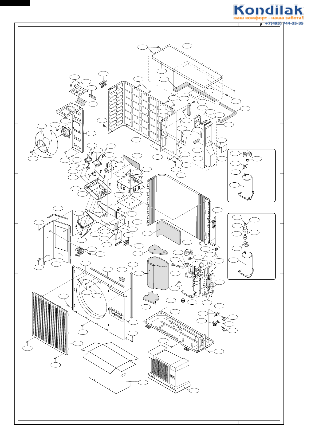
54
AH-X08BE/10BE/13BE
AY-X08BE/10BE/13BE
AY-X08BE-C/10BE-C
AU-X08BE/10BE/13BE
AE-X08BE/10BE/13BE
AE-X08BE-C/10BE-C
A
B
C
D
E
F
G
H
A
123456
123456
B
C
D
E
F
G
H
OUTDOOR UNIT FOR AE-X08BE/X08BE-C/X10BE/X10BE-C/X13BE AND AU-X08BE/X10BE/X13BE
2-33
2-23
2-30
4-4
2-14
2-4
2-3
2-25
2-31
1-26
3-3
4-1
4-1
4-1
3-17
3-21
2-9
4-1
4-1
3-20
2-10
2-6
2-19
1-46
2-13
3-9
3-19
3-4
3-7
3-18
3-15
1-4
4-13
1-3-b
1-3-a
1-23
1-55
2-29
4-1
4-6
1-54
4-12
1-10
1-25
4-6
1-19
1-5
4-17
1-27
1-15
4-1
4-1
4-9
4-9
1-13
1-11
4-11
1-12
1-22
4-7
1-14
1-57
1-56
4-12
3-16
2-11
2-12
4-14
4-1
4-1
4-2
4-2
2-7
4-1
4-1
4-14
4-1
4-5
1-17
3-2
3-1
3-2
2-16
1-18
4-15
2-28
4-1
4-1
4-4
2-2
1-1
2-18
4-10
2-1
4-14
2-5
4-1
2-8
2-32
2-22
1-17
4-3
4-14
2-15
2-35
2-34
2-24
2-26
2-27
4-14
4-14
1-21
4-4
4-1
1-16
2-17
3-11
3-10
3-22
6-2
Front side
6-1
AE-X08BE/X10BE
AE-X10BE-C
AU-X13BE
3-9
1-16
2-17
3-11
3-10
1-16
3-11
3-12
3-14
3-13
AE-X08BE-C
AU-X08BE/X10BE
3-9
2-17
2-21

AH-X08BE/10BE/13BE
AY-X08BE/10BE/13BE
AY-X08BE-C/10BE-C
AU-X08BE/10BE/13BE
AE-X08BE/10BE/13BE
AE-X08BE-C/10BE-C
MEMO

AH-X08BE/10BE/13BE
AY-X08BE/10BE/13BE
AY-X08BE-C/10BE-C
AU-X08BE/10BE/13BE
AE-X08BE/10BE/13BE
AE-X08BE-C/10BE-C
2002 SHARP CORP. (7) Printed in the Netherlands