
2
En
WARNING: TO PREVENT FIRE OR SHOCK
HAZARD, DO NOT EXPOSE THIS APPLIANCE TO
RAIN OR MOISTURE.
IMPORTANT
The lightning flash with arrowhead symbol,
within an equilateral triangle, is intended to
alert the user to the presence of uninsulated
"dangerous voltage" within the product's
enclosure that may be of sufficient magnitude
to constitute a risk of electric shock to persons.
The exclamation point within an equilateral
triangle is intended to alert the user to the
presence of important operating and
maintenance (servicing) instructions in the
literature accompanying the appliance.
CAUTION:
TO PREVENT THE RISK OF ELECTRIC SHOCK,
DO NOT REMOVE COVER (OR BACK). NO
USER-SERVICEABLE PARTS INSIDE. REFER
SERVICING TO QUALIFIED SERVICE
PERSONNEL.
RISK OF ELECTRIC SHOCK
DO NOT OPEN
CAUTION
Information to User
Alteration or modifications carried out without appropriate authorization may invalidate the user's right to
operate the equipment.
THE STANDBY/ON BUTON IS SECONDARY
CONNECTED AND THEREFORE DOES NOT
SEPARATE THE UNIT FROM MAINS POWER
IN STANDBY POSITION.
NOTE: This equipment has been tested and found to comply with the limits for a Class B digital device,
pursuant to Part 15 of the FCC Rules. These limits are designed to provide reasonable protection against harmful
interference in a residential installation. This equipment generates, uses, and can radiate radio frequency energy
and, if not installed and used in accordance with the instructions, may cause harmful interference to radio
communications. However, there is no guarantee that interference will not occur in a particular installation. If
this equipment does cause harmful interference to radio or television reception, which can be determined by
turning the equipment off and on, the user is encouraged to try to correct the interference by one or more of the
following measures:
– Reorient or relocate the receiving antenna.
– Increase the separation between the equipment and receiver.
– Connect the equipment into an outlet on a circuit different from that to which the receiver is connected.
– Consult the dealer or an experienced radio/TV technician for help.
IMPORTANT NOTICE
The serial number for this equipment is located on the
rear panel. Please write this serial number on your en-
closed warranty card and keep it in a secure area. This
is for your security.
[For Canadian model]
This Class B digital apparatus complies with
Canadian ICES-003.
[Pour le modèle Canadien]
Cet appareil numérique de la classe B est
conforme à la norme NMB-003 du Canada.
[For Canadian model]
CAUTION: TO PREVENT ELECTRIC SHOCK DO NOT
USE THIS (POLARIZED) PLUG WITH AN EXTENSION
CORD, RECEPTACLE OR OTHER OUTLET UNLESS THE
BLADES CAN BE FULLY INSERTED TO PREVENT BLADE
EXPOSURE.
ATTENTION: POUR PREVENIR LES CHOCS
ELECTRIQUES NE PAS UTILISER CETTE FICHE
POLARISEE AVEC UN PROLONGATEUR, UNE PRISE DE
COURANT OU UNE AUTRE SORTIE DE COURANT,
SAUF SI LES LAMES PEUVENT ETRE INSERESS A
FOND SANS EN LAISSER AUCUNE PARTIE A
DECOUVERT.
Manufactured under license from Dolby Labo-
ratories. "Dolby", "Pro Logic" and the double-D
symbol are trademarks of Dolby Laboratories.
Confidential Unpublished Works. © 1992-1997
Dolby Laboratories, Inc. All rights reserved.
"DTS" ,"ES" and "DTS Digital Surround" are
trademarks of Digital Theater Systems, Inc.
Manufactured under license from Digital
Theater Systems, Inc.
If the socket outlets on the associated equipment are not
suitable for the plug supplied with the product, the plug must
be removed and an appropriate one fitted. Replacement and
mounting of an AC plug on the power supply cord of this unit
should be perfomed only by qualified service personnel. The
cut-off plug must be disposed of as an electrical shock hazard
could exist if connected to a socket outlet.
H022AEn
3
En
READ INSTRUCTIONS — All the safety
and operating instructions should be
read before the product is operated.
RETAIN INSTRUCTIONS — The safety and
operating instructions should be retained
for future reference.
HEED WARNINGS — All warnings on the
product and in the operating instructions
should be adhered to.
FOLLOW INSTRUCTIONS — All operating
and use instructions should be followed.
CLEANING — Unplug this product from the
wall outlet before cleaning. The product
should be cleaned only with a polishing
cloth or a soft dry cloth. Never clean
with furniture wax, benzine, insecticides
or other volatile liquids since they may
corrode the cabinet.
ATTACHMENTS — Do not use attachments
not recommended by the product
manufacturer as they may cause
hazards.
WATER AND MOISTURE — Do not use
this product near water — for example,
near a bathtub, wash bowl, kitchen sink,
or laundry tub; in a wet basement; or
near a swimming pool; and the like.
ACCESSORIES — Do not place this product
on an unstable cart, stand, tripod,
bracket, or table. The product may fall,
causing serious injury to a child or adult,
and serious damage to the product. Use
only with a cart, stand, tripod, bracket,
or table recommended by the
manufacturer, or sold with the product.
Any mounting of the product should
follow the manufacturer’s instructions,
and should use a mounting accessory
recommended by the manufacturer.
CART — A product and cart combination
should be moved with care. Quick stops,
excessive force, and uneven surfaces
may cause the product and cart
combination to overturn.
VENTILATION — Slots and openings in the
cabinet are provided for ventilation and
to ensure reliable operation of the
product and to protect it from
overheating, and these openings must
not be blocked or covered. The openings
should never be blocked by placing the
product on a bed, sofa, rug, or other
similar surface. This product should not
be placed in a built-in installation such
as a bookcase or rack unless proper
ventilation is provided or the
manufacturer’s instructions have been
adhered to.
POWER SOURCES — This product should
be operated only from the type of power
source indicated on the marking label. If
you are not sure of the type of power
supply to your home, consult your
product dealer or local power company.
LOCATION – The appliance should be
installed in a stable location.
NONUSE PERIODS – The power cord of
the appliance should be unplugged from
the outlet when left unused for a long
period of time.
GROUNDING OR POLARIZATION
÷ If this product is equipped with a
polarized alternating current line plug (a
plug having one blade wider than the
other), it will fit into the outlet only one
way. This is a safety feature. If you are
unable to insert the plug fully into the
outlet, try reversing the plug. If the plug
should still fail to fit, contact your
electrician to replace your obsolete
outlet. Do not defeat the safety purpose
of the polarized plug.
÷ If this product is equipped with a three-
wire grounding type plug, a plug having
a third (grounding) pin, it will only fit into
a grounding type power outlet. This is a
safety feature. If you are unable to insert
the plug into the outlet, contact your
electrician to replace your obsolete
outlet. Do not defeat the safety purpose
of the grounding type plug.
POWER-CORD PROTECTION — Power-
supply cords should be routed so that
they are not likely to be walked on or
pinched by items placed upon or against
them, paying particular attention to cords
at plugs, convenience receptacles, and
the point where they exit from the
product.
OUTDOOR ANTENNA GROUNDING — If
an outside antenna or cable system is
connected to the product, be sure the
antenna or cable system is grounded so
as to provide some protection against
voltage surges and built-up static
charges. Article 810 of the National
Electrical Code, ANSI/NFPA 70, provides
information with regard to proper
grounding of the mast and supporting
structure, grounding of the lead-in wire
to an antenna discharge unit, size of
grounding conductors, location of
antenna-discharge unit, connection to
grounding electrodes, and requirements
for the grounding electrode. See Figure
A.
LIGHTNING — For added protection for this
product during a lightning storm, or when
it is left unattended and unused for long
periods of time, unplug it from the wall
outlet and disconnect the antenna or
cable system. This will prevent damage
to the product due to lightning and
power-line surges.
POWER LINES — An outside antenna
system should not be located in the
vicinity of overhead power lines or other
electric light or power circuits, or where
it can fall into such power lines or circuits.
When installing an outside antenna
system, extreme care should be taken
to keep from touching such power lines
or circuits as contact with them might
be fatal.
OVERLOADING — Do not overload wall
outlets, extension cords, or integral
convenience receptacles as this can
result in a risk of fire or electric shock.
OBJECT AND LIQUID ENTRY — Never
push objects of any kind into this product
through openings as they may touch
dangerous voltage points or short-out
parts that could result in a fire or electric
shock. Never spill liquid of any kind on
the product.
SERVICING — Do not attempt to service
this product yourself as opening or
removing covers may expose you to
dangerous voltage or other hazards.
Refer all servicing to qualified service
personnel.
DAMAGE REQUIRING SERVICE — Unplug
this product from the wall outlet and
refer servicing to qualified service
personnel under the following
conditions:
÷ When the power-supply cord or plug is
damaged.
÷ If liquid has been spilled, or objects
have fallen into the product.
÷ If the product has been exposed to rain
or water.
÷ If the product does not operate normally
by following the operating instructions.
Adjust only those controls that are
covered by the operating instructions
as an improper adjustment of other
controls may result in damage and will
often require extensive work by a
qualified technician to restore the
product to its normal operation.
÷ If the product has been dropped or
damaged in any way.
÷ When the product exhibits a distinct
change in performance — this indicates
a need for service.
REPLACEMENT PARTS — When
replacement parts are required, be sure
the service technician has used
replacement parts specified by the
manufacturer or have the same
characteristics as the original part.
Unauthorized substitutions may result
in fire, electric shock, or other hazards.
SAFETY CHECK — Upon completion of any
service or repairs to this product, ask
the service technician to perform safety
checks to determine that the product is
in proper operating condition.
WALL OR CEILING MOUNTING — The
product should not be mounted to a
wall or ceiling.
HEAT — The product should be situated
away from heat sources such as
radiators, heat registers, stoves, or other
products (including amplifiers) that
produce heat.
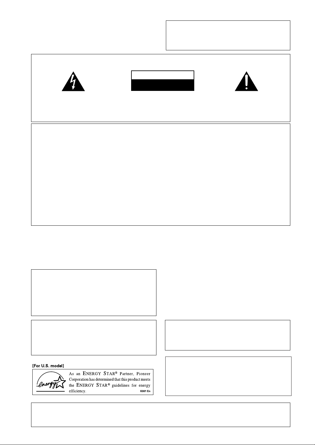
IMPORTANT SAFETY INSTRUCTIONS
GROUND
CLAMP
ANTENNA
DISCHARGE UNIT
(NEC SECTION 810-20)
GROUNDING CONDUCTORS
(NEC SECTION 810-21)
GROUND CLAMPS
POWER SERVICE GROUNDING
ELECTRODE SYSTEM
(NEC ART 250, PART H)
ELECTRIC
SERVICE
EQUIPMENT
Fig. A
ANTENNA
LEAD IN
WIRE
NEC — NATIONAL ELECTRICAL CODE
4
En
01
Introductory Information
Checking the Supplied
Accessories
Please check that you've received the following supplied
accessories:
• AM loop antenna
• FM wire antenna
• Dry Cell Batteries x2
(VSX-D710S/D810S : type AA IEC R6P)
(VSX-D850S : type AA IEC LR6)
• Remote Control Unit
• Operating Instructions
Using this Manual
This manual is for the VSX-D710S/D810S/D850S audio/
video multi-channel receivers.
It is divided into two main sections:
Set up
This section covers installing your receiver and
connecting up all the other components in your home
theater system to it. It also describes how to set up a
multi-channel speaker system to take full advantage of
the great surround sound features of your receiver.
Operation
This section shows you how to use every feature of the
receiver and its remote control unit. It also covers using
the supplied remote control to operate your other home
theater components. To find out more about a specific
button, control or indicator, see Displays & Controls
starting on page 22. This will point you to the relevant
chapter in the manual.
In the Additional Information section (p.50-51) you'll
find a troubleshooting section and specifications.
Installing the Receiver
Please note:
• Do not place objects directly on top of this unit. This
would prevent proper heat dispersal.
• When installing in a rack, shelf, etc., be sure to leave
more than 8 inches (20 cm.) of space above the
receiver.
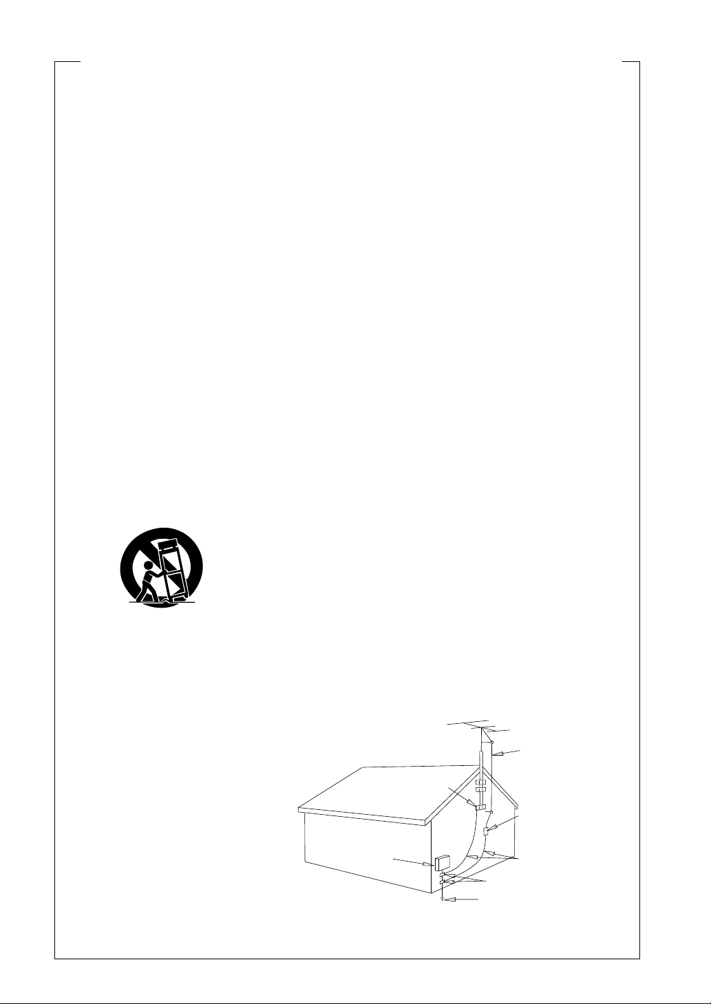
When Making Cable
Connections
Be careful not to arrange cables in a manner that bends
the cables over the top of this unit. If the cables are laid
on top of the unit, the magnetic field produced by the
transformers in this unit may cause a humming noise to
come from the speakers.
Loading the Batteries
Dry Cell Batteries × 2
CAUTION:
Incorrect use of batteries may result in such hazards as
leakage and bursting. Observe the following precautions:
• Never use new and old batteries together.
• Insert the plus and minus sides of the batteries
properly according to the marks in the battery case.
• Batteries of the same shape may have different
voltages. Do not use different batteries together.
• When disposing of used batteries, please comply
with governmental regulations or environmental
public institution’s rules that apply in your country or
area.
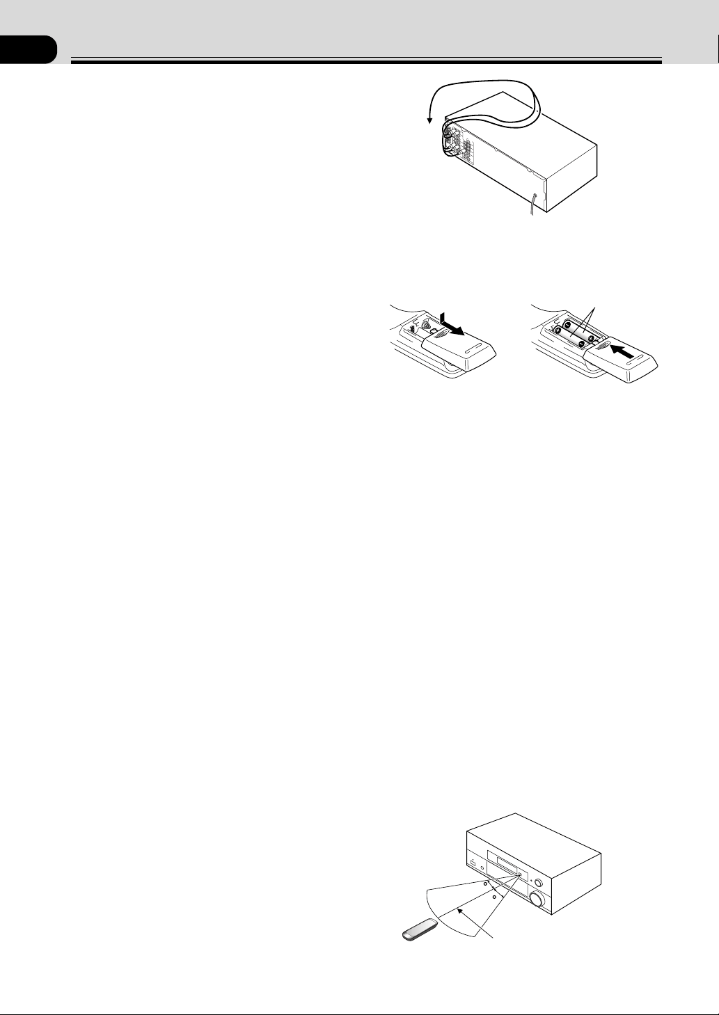
Operating Range of Remote
Control Unit
The remote control may not work properly if:
• There are obstacles between the remote control and
the receiver's remote sensor.
• Direct sunlight or fluorescent light is shining onto the
remote sensor.
• The receiver is located near a device that is emitting
infrared rays.
• The receiver is operated simultaneously with another
infrared remote control unit.
30
30
23ft (7m)

5
En
02
01 Introductory Information 4
Checking the Supplied Accessories 4
Using this Manual 4
Installing the Receiver 4
When Making Cable Connections 4
Loading the Batteries 4
Operating Range of Remote Control Unit 4
02 Contents 5
03 Connecting Your Equipment 6
Audio/Video Cords 6
Digital audio Cords/Optical Cables 6
Connecting Digital Components 6
Example Connection for a DVD/LD or LD Player 7
Connecting Audio Components 8
Connecting DVD 7.1 Channel (5.1 for VSX-D710S)
Components 9
Connecting Video Components 10
Connecting Antennas 11
Connecting Speakers (VSX-D710S) 12
Connecting Speakers (VSX-D810S/D850S) 13
Hints on Speaker Placement 14
Connecting Additional Amplifiers (VSX-D810S/
D850S only) 15
AC Outlet [switched 100 W (0.8 A) max] 15
04 Preparations 16
Setting Up for Surround Sound 16
Setting the Volume Level of Each Channel 21
05 Displays & Controls 22
Front Panel 22
Display 23
Remote Control (VSX-D710S/D810S) 24
Remote Control (VSX-D850S) 26
LCD Display (VSX-D850S only) 26
06 Sound Modes 27
Learning about the Sound Modes 27
Switching ANALOG/DIGITAL Signal Input 29
Playing Sources with Dolby Digital or
DTS Sound 29
Selecting a Sound Mode 30
Contents
Sorround operation 30
ADVANCED THEATER mode
( Dolby/DTS mode) 30
DVD 5.1 ch/7.1ch (5.1 ch for VSX-D710S) input
playback 31
MIDNIGHT Listening Mode 31
Playing other Source 31
07 Using the Tuner 32
Finding a Station 32
Tuning Directly to a Station 32
Memorizing Stations 33
Recalling Memorized Stations 33
08 Making a Recording 34
Making an Audio or a Video Recording 34
Record MONITOR 34
Making a Digital Recording 34
09 Controlling the Rest of Your System 35
Recalling Preset Codes 35
Setting Up Using Preset Code Search (VSX-
D710S/D810S) 36
Setting Up Using Library Search (VSX-D850S)
36
Setting Up Using Brand Name Search (VSX-850
only) 37
Learning Mode: Programming Signals from other
Remote Controls 38
Erasing One of the Remote Control button
Settings 39
Clearing All the Remote Control Settings 39
Direct Function 39
Checking Preset Code 40
Operating other Pioneer Components 40
CD/MD/CD-R/VCR/DVD/LD/DVR Player/
Cassette Deck Controls 41
Cable TV/Satellite TV/TV/DTV Controls 42
Preset Code List 43
10 Additional Information 50
Troubleshooting 50
Specifications 51
Congratulations on buying this fine Pioneer product.
Please read through these operating instructions so you will know how to operate your model
properly. After you have finished reading the instructions, put them away in a safe place for
future reference.
6
En
LR
LR
RL
S
FRONT
LR
FRONT
LR
SURROUNDCENTER
COMPONENT
VIDEO
DIGITAL IN
PCM/2/DTS
DIGITAL
OUT
TO
MONTOR
TV
TO
MONTOR
TV
VCR /
DVR
VIDEO
VIDEO
VCR /
DVR
TO MONITOR TV OUT
CONTROL
IN
AUX
CD
IN
OUT
IN
IN OUT
OUT
CD - R
/ TAPE
/ MD
SURROUND
CENTER
SUB W.
SUB W.
PREOUT
IN
IN
IN
YP
B
P
R
YP
B
P
R
S
IN
S
IN
S
OUT
S
OUT
IN
IN
IN
TV /
SAT
TV /
SAT
DVD/
LD
DVD
/ LD
FRONT
CENTER
PREOUT
(DVD) (CD) (CD-R)
COAX OPT OPT OPT
R
E
C
P
L
A
Y
A B
1 2
1
(TV/SAT) IN
(DVD/LD) IN
2
OUT
FM
UNBAL75Ω
ANTENNA
AM
LOOP
DVD 5.1 CH INPUT
SPEAKERS
DIGITAL OUT
DIGITAL
OUT
COAX
DIGITAL
OUT
DIGITAL
IN
VSX-D710S
03
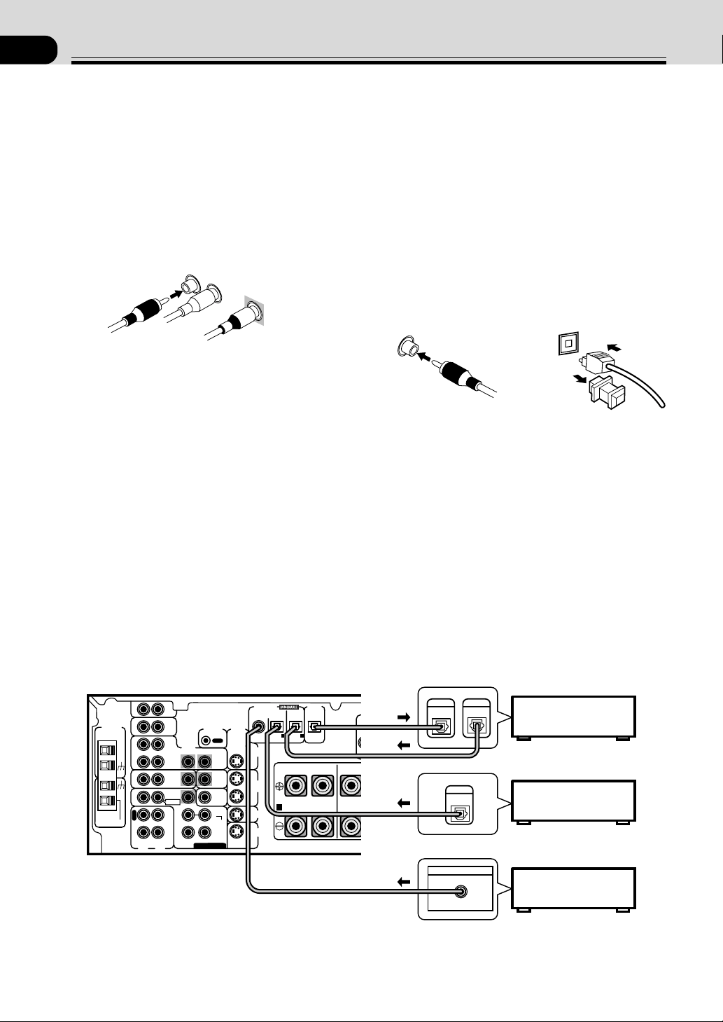
Digital Audio Cords/Optical
Cables
Commercially available digital audio coaxial cords
(standard video cords can also be used) or optical cables
(not supplied) are used to connect digital components to
this receiver.
When you use optical digital input or output terminals,
pull off the caps and insert the plugs. Be sure to insert
completely.
Digital audio cord
(or standard video cord)
Optical cable
Connecting Your Equipment
Audio/Video Cords
Use audio/video cords (not supplied) to make analog
audio and video connections.
Connect red plugs to R (right), white plugs to L (left),
and the yellow plugs to VIDEO.
Be sure to insert completely.
L
R
VIDEO
Connecting Digital Components
In order to use PCM/
22
22
2 Digital/DTS soundtracks, you need to make digital audio connections.
You can do this by either coaxial or optical connections (you do not need to do both). The quality of these two types
of connections is the same but since some digital components only have one type of digital terminal, it is a matter of
matching like with like (for example, the coaxial out from the component to coaxial in on the receiver). The VSX-
D710S has a coaxial input and two optical inputs for a total of three digital inputs. The VSX-D810S has a coaxial
input and three optical inputs for a total of four digital inputs and the VSX-D850S has a coaxial input and four
optical inputs for a total of five digital inputs. Connect your digital components as shown below. There is one digital
out jack which is marked DIGITAL OUT. If you connect this to the optical input on a digital recorder (currently these
include MD, DAT and CD-R) you can make direct digital recordings with this unit.
When connecting your equipment, always make sure the power is turned off and the power cord is disconnected
from the wall outlet.
DVD player
CD player
CD recorder
The arrows indicate the direction of the audio signal.
Before making or changing the connections, switch off the power and disconnect the power cord from the AC wall
outlet.
7
En
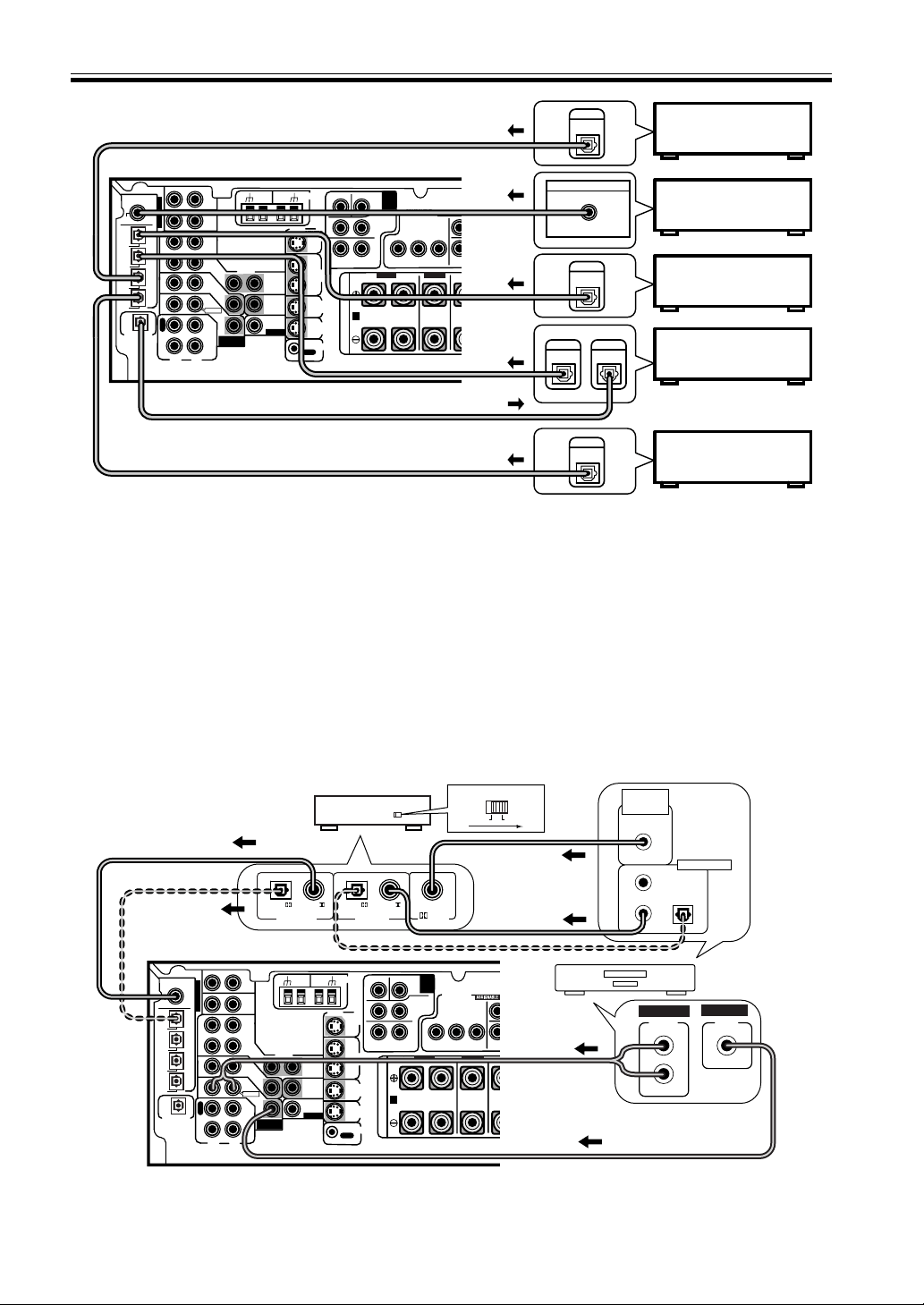
Example Connection for a DVD/LD or LD Player
Since some LDs have soundtracks recorded on the special 2 RF format you need to make special hook ups to ensure
you can play all LDs on your system. If you don't have an LD (or an LD player with your DVD player) you don't need
to worry about this. For the VSX-D710S/D810S/D850S hook up your DVD/LD or LD player directly and make sure
you make both a 2 RF output and either a coaxial or optical digital connection. Of course you must hook up your
DVD/LD or LD player with standard (coaxial or optical) digital connections but if you are able to hook up your player
with a 2 RF output (if your player has one) this will ensure you can use all LDs available. We also recommend
hooking up your digital components to analog audio jacks as well.
Before making or changing the connections, switch off the power and disconnect the power cord from the AC wall
outlet. The diagram is for the VSX-D850S but hook up an RF Demodualtor to the VSX-D710S in the same manner.
L
R
R
R
L
L
L
R
L
R
BACK
LR
VIDEO
AC OUTLET
VIDEO
COMPONENT
VIDEO
FRONT
CENTER
SURROUND
SURROUND
BACK
TO
MONTOR
TV
TO
MONTOR
TV OUT
VCR /
DVR
DIGITAL IN
TO MONITOR TV OUT
CENTER
SUB WOOFER
SURROUND
SURROUND BACK
CONTROL
IN
IN
IN
AUX
IN
CD
IN
(DVD)
(CD)
PCM/
2
/DTS
C
O
A
X
O
P
T
¥
O
P
T
ø
O
P
T
π
O
P
T
[
O
P
T
IN
IN
IN
OUT
OUT
CD - R
/ TAPE
/ MD
SUB
WOOFER
DIGITAL OUT
Y
Y
L
R
L
R
P
B
P
B
P
R
P
R
IN
TV /
SAT
TV /
SAT
DVD
/ LD
DVD/
LD
FRONT
O
U
T
R
E
C
P
L
A
Y
A
(DVD/LD) IN
1
(TV/SAT) IN
2
B
VCR /
DVR
S
IN
S
IN
S
IN
S
OUT
S
OUT
PREOUT
(TV)
(VCR)
(CD-R)
OUT
FM
UNBAL
75Ω
AM
LOOP
ANTENNA
DVD 7.1 CH
INPUT
DVD
7.1 CH
INPUT
PREOUT
FRONT FRONT
SURROUND
CENTER
PREOUT
ASSIGNABLE
S
P
E
A
K
E
R
S
DIGITAL OUT
DIGITAL
OUT
COAX
DIGITAL
OUT
DIGITAL
IN
DIGITAL
OUT
DIGITAL
OUT
VSX-D810S/D850S
VSX-D850S only
DVD player
CD player
CD recorder
TV tuner
(or Satellite tuner)
VCR
Connecting Your Equipment
L
R
R
R
L
L
L
R
L
R
BACK
LR
VIDEO
AC OUTLET
VIDEO
COMPONENT
VIDEO
FRONT
CENTER
SURROUND
SURROUND
BACK
TO
MONTOR
TV
TO
MONTOR
TV OUT
VCR /
DVR
DIGITAL IN
TO MONITOR TV OUT
CENTER
SUB WOOFER
SURROUND
SURROUND BACK
CONTROL
IN
IN
IN
AUX
IN
CD
IN
(DVD)
(CD)
PCM/
2
/DTS
C
O
A
X
O
P
T
¥
O
P
T
ø
O
P
T
π
O
P
T
[
O
P
T
IN
IN
IN
OUT
OUT
CD - R
/ TAPE
/ MD
SUB
WOOFER
DIGITAL OUT
Y
Y
L
R
L
R
P
B
P
B
P
R
P
R
IN
TV /
SAT
TV /
SAT
DVD
/ LD
DVD/
LD
FRONT
O
U
T
R
E
C
P
L
A
Y
A
(DVD/LD) IN
1
(TV/SAT) IN
2
B
VCR /
DVR
S
IN
S
IN
S
IN
S
OUT
S
OUT
PREOUT
(TV)
(VCR)
(CD-R)
OUT
FM
UNBAL
75Ω
AM
LOOP
ANTENNA
DVD 7.1 CH
INPUT
DVD
7.1 CH
INPUT
PREOUT
FRONT FRONT
SURROUND
CENTER
PREOUT
ASSIGNABLE
S
P
E
A
K
E
R
S
RF demodulator RFD-1
DIGITAL IN
PCM/
(OPT.)
PCM/
RF IN
(AC-3)(LD)
DIGITAL OUT
PCM/
(OPT.)
PCM/
OPTICAL
COAXIAL
DIGITAL IN
VSX-D850S
1
23
DIGITAL OUT
(AC-3)(LD)
RF OUT
2
DVD/LD player
or LD player
VIDEO
OUT
VIDEO
STEREO
L
R
ANALOG
MEMO:
Be sure to make either a digital coaxial or digital optical connection as well, but you don't need to make both. Make
sure the RF demodulator digital in switch is set correctly (optical or coaxial depending on the connection). See the
component's instruction manual if you are unsure about its input and output jacks.
The arrows indicate the direction of the audio signal.
8
En
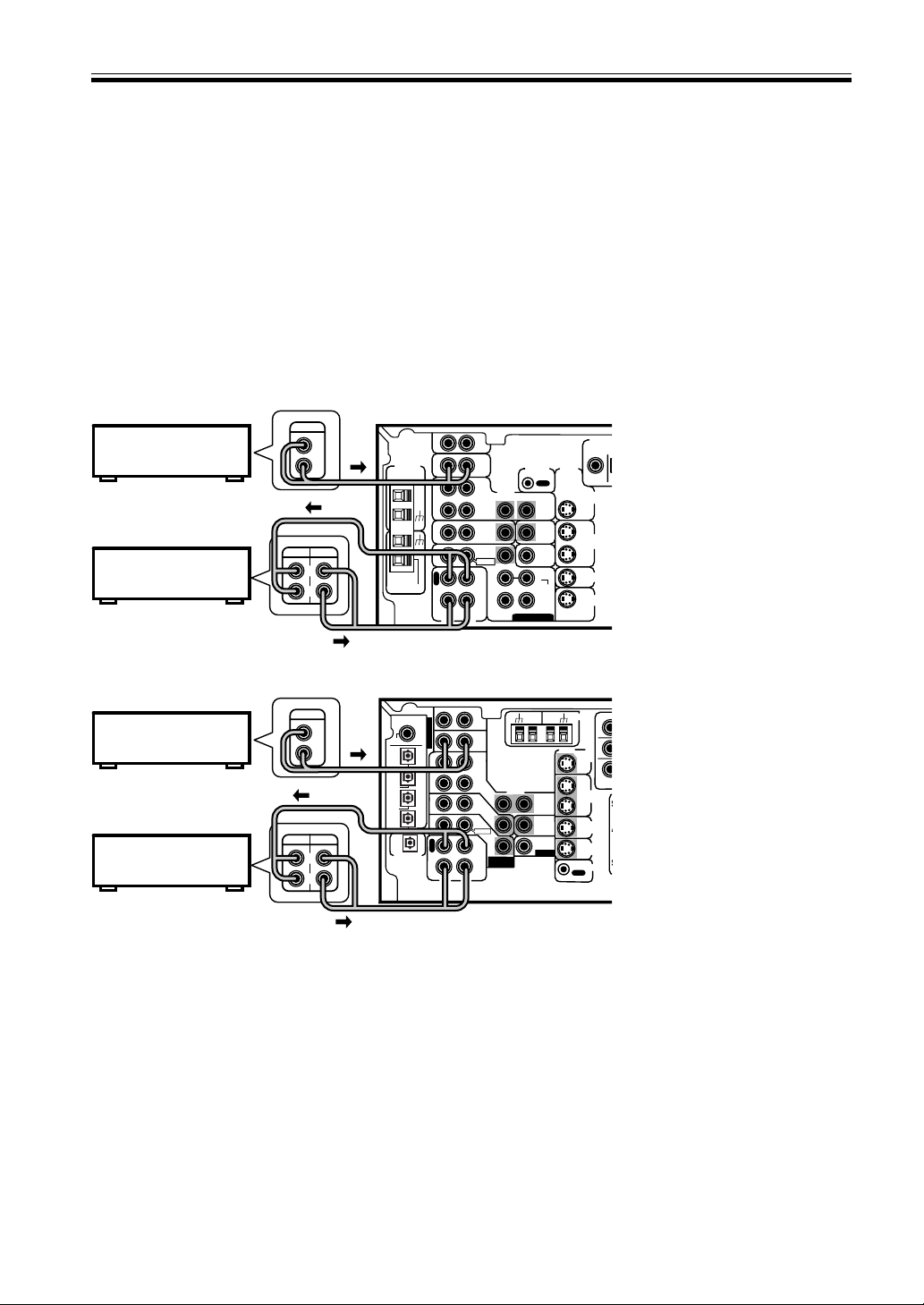
Connecting Your Equipment
Connecting Audio Components
To begin set up, connect your audio components to the jacks as shown below. These are all analog connections and
your analog audio components (like a cassette deck) use these jacks. Remember that for components you want to
record with you need to hook up four plugs (a set of stereo ins and a set of stereo outs), but for components that only
play you only need to hook up one set of stereo plugs (two plugs). To use digital source features you must hook up
your digital components to the digital inputs (see the previous page for more on digital connections) but it is also a
good idea to hook up your digital components to these analog audio jacks. If you want to record to/from digital
components (like an MD) to/from analog components, you must hook up your digital equipment with these analog
connections.
When connecting your equipment, always make sure the power is turned off and the power cord is disconnected
from the wall outlet.
The arrows indicate the direction of the audio signal.
R
R
LR
VIDEO
VIDEO
TO
MONTOR
TV
TO
MONTOR
TV OUT
VCR /
DVR
DIGITAL IN
CENT
E
SU
R
CONTROL
IN
IN
IN
AUX
IN
CD
IN
(DVD)
(CD)
PCM/
2
/DTS
C
O
A
X
O
P
T
¥
O
P
T
ø
O
P
T
π
O
P
T
[
O
P
T
IN
IN
IN
OUT
OUT
CD - R
/ TAPE
/ MD
SUB
WOOFER
DIGITAL OUT
IN
TV /
SAT
TV /
SAT
DVD
/ LD
DVD/
LD
FRONT
O
U
T
R
E
C
P
L
A
Y
VCR /
DVR
S
IN
S
IN
S
IN
S
OUT
S
OUT
PREOUT
(TV)
(VCR)
(CD-R)
OUT
FM
UNBAL
75Ω
AM
LOOP
ANTENNA
DVD 7.1 CH
INPUT
PREOUT
ASSIGNABLE
S
A
S
REC
PLAY
L
R
L
R
OUTPUT
VSX-D810S/D850S
LR
RL
S
DIGITAL
PCM/2/
D
TO
MONTOR
TV
TO
MONTOR
TV
VCR /
DVR
VIDEO
VIDEO
VCR /
DVR
CONTROL
IN
AUX
CD
IN
OUT
IN
IN OUT
OUT
CD - R
/ TAPE
/ MD
SURROUND
CENTER
SUB W.
SUB W.
PREOUT
IN
IN
IN
S
IN
S
IN
S
OUT
S
OUT
IN
IN
IN
TV /
SAT
TV /
SAT
DVD/
LD
DVD
/ LD
FRONT
(DVD)
COAX
R
E
C
P
L
A
Y
OUT
FM
UNBAL75Ω
ANTENNA
AM
LOOP
DVD 5.1 CH INPUT
REC
PLAY
L
R
L
R
OUTPUT
VSX-D710S
CD player
CD recorder
or Cassette deck
Cassette deck placement
Depending on where the cassette
deck is placed, noise may occur
during playback of your cassette
deck which is caused by leakage
flux from the transformer in the
receiver. If you experience noise,
move the cassette deck farther
away from the receiver.
CD player
CD recorder
or Cassette deck
9
En
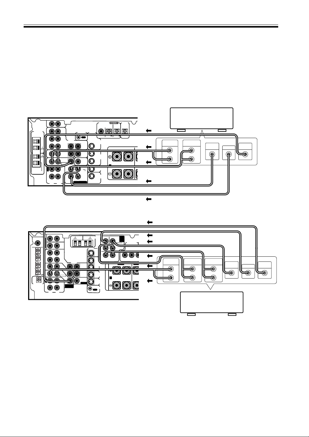
Connecting DVD 7.1 Channel (5.1 ch for VSX-D710S) Components
DVD and LD discs are compatible with both 2 channel and 7.1 channel audio output formats. Connections can be
made from a DVD player/multi-channel decoder equipped with 7.1 analog outputs to the 6.1 analog inputs on this
unit (the surround back channel is mono on the VSX-D810S/D850S models so we refer to it as 6.1 ch). You need to
connect both the left and right surround back channels for the VSX-D810S/D850S models but the sound from this
channel will only be mono. Always make sure that the receiver is switched off and unplugged from the wall outlet
before making or changing any connections.
MEMO:
• The 7.1 channel (5.1 channel for VSX-D710S) input can only be used when DVD 7.1 ch (5.1 channel for VSX-
D710S) input is selected.
• For 6.1 channel output select the SB 1ch setting (see p. 20). In this case you can connect the single surround back
speaker to either the left or right surround back terminals.
Connecting Your Equipment
L
R
R
R
L
L
L
R
L
R
BACK
LR
VIDEO
AC OUTLET
VIDEO
COMPONENT
VIDEO
FRONT
CENTER
SURROUND
SURROUND
BACK
TO
MONTOR
TV
TO
MONTOR
TV OUT
VCR /
DVR
DIGITAL IN
TO MONITOR TV OUT
CENTER
SUB WOOFER
SURROUND
SURROUND BACK
CONTROL
IN
IN
IN
AUX
IN
CD
IN
(DVD)
(CD)
PCM/
2
/DTS
C
O
A
X
O
P
T
¥
O
P
T
ø
O
P
T
π
O
P
T
[
O
P
T
IN
IN
IN
OUT
OUT
CD - R
/ TAPE
/ MD
SUB
WOOFER
DIGITAL OUT
Y
Y
L
R
L
R
P
B
P
B
P
R
P
R
IN
TV /
SAT
TV /
SAT
DVD
/ LD
DVD/
LD
FRONT
O
U
T
R
E
C
P
L
A
Y
A
(DVD/LD) IN
1
(TV/SAT) IN
2
B
VCR /
DVR
S
IN
S
IN
S
IN
S
OUT
S
OUT
PREOUT
(TV)
(VCR)
(CD-R)
OUT
FM
UNBAL
75Ω
AM
LOOP
ANTENNA
DVD 7.1 CH
INPUT
DVD
7.1 CH
INPUT
PREOUT
FRONT FRONT
SURROUND
CENTER
PREOUT
ASSIGNABLE
S
P
E
A
K
E
R
S
CENTER
SUB
WOOFER
VIDEO
OUT
SURROUND
OUTPUT
L
R
SURROUND
BACK OUTPUT
L
R
FRONT
OUTPUT
L
R
VSX-D810S/D850S
LR
LR
RL
S
FRONT
LR
FRONT
LR
SURROUNDCENTER
COMPONENT
VIDEO
DIGITAL IN
PCM/2/DTS
DIGITAL
OUT
TO
MONTOR
TV
TO
MONTOR
TV
VCR /
DVR
VIDEO
VIDEO
VCR /
DVR
TO MONITOR TV OUT
CONTROL
IN
AUX
CD
IN
OUT
IN
IN OUT
OUT
CD - R
/ TAPE
/ MD
SURROUND
CENTER
SUB W.
SUB W.
PREOUT
IN
IN
IN
YP
B
P
R
YP
B
P
R
S
IN
S
IN
S
OUT
S
OUT
IN
IN
IN
TV /
SAT
TV /
SAT
DVD/
LD
DVD
/ LD
FRONT
CENTER
PREOUT
(DVD) (CD) (CD-R)
COAX OPT OPT OPT
R
E
C
P
L
A
Y
A B
1 2
1
(TV/SAT) IN
(DVD/LD) IN
2
OUT
FM
UNBAL75Ω
ANTENNA
AM
LOOP
DVD 5.1 CH INPUT
SPEAKERS
CENTER
SUB
WOOFER
VIDEO
OUT
SURROUND
OUTPUT
L
R
FRONT
OUTPUT
L
R
VSX-D710S
The arrows indicate the direction of the audio signal.
DVD/multi channel
decoder with 5.1 channel
analog output jacks
DVD/multi channel
decoder with 7.1 channel
analog output jacks
10
En
LR
LR
RL
S
FRONT
LR
SURROUNDCENTER
COMPONENT
VIDEO
DIGITAL IN
PCM/2/DTS
DIGITAL
OUT
TO
MONTOR
TV
TO
MONTOR
TV
VCR /
DVR
VIDEO
VIDEO
VCR /
DVR
TO MONITOR TV OUT
CONTROL
IN
AUX
CD
IN
OUT
IN
IN OUT
OUT
CD - R
/ TAPE
/ MD
SURROUND
CENTER
SUB W.
SUB W.
PREOUT
IN
IN
IN
YP
B
P
R
YP
B
S
IN
S
IN
S
OUT
S
OUT
IN
IN
IN
TV /
SAT
TV /
SAT
DVD/
LD
DVD
/ LD
FRONT
CENTER
PREOUT
(DVD) (CD) (CD-R)
COAX OPT OPT OPT
R
E
C
P
L
A
Y
A
1 2
1
(TV/SAT) IN
(DVD/LD) IN
2
OUT
FM
UNBAL75Ω
ANTENNA
AM
LOOP
DVD 5.1 CH INPUT
SPEAKERS
OUTPUT
VIDEO
L
R
OUTPUT
INPUT
VIDEO
L
R
VIDEO
L
R
OUTPUT
VIDEO
L
R
INPUT
VIDEO
VSX-D710S
Connecting Your Equipment
DVD player
(or LD player)
Video deck
TV tuner
(or Satellite tuner)
TV
(monitor)
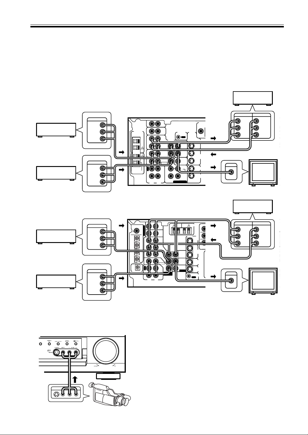
Front
Front video connections are accessed via the front panel
input selector as “VIDEO.”
MEMO:
This receiver also has S-Video and component video inputs
and outputs. These can give you a better picture than the
standard composite video connections. For S-Video
connections use an S-Video cord (not supplied); for
component video connections use a three-way RCA cord (not
supplied).
Note that a signal fed into a video input on this receiver is
only sent to your TV from the corresponding video output.
In other words, if you connect your VCR to this receiver
using a standard video cord, you need to connect the receiver
to your TV using a standard video cord. If your DVD player
is connected using an S-Video cord, make sure that you also
connect the receiver to your TV with an S-Video cord.
Connecting Video Components
Connect your video components to the jacks as shown below. Regarding digital video components (like a DVD
player), you must use the analog video connections pictured on this page for the video signal but in order to use a
digital source (like a DVD) you must hook up their audio to a digital audio input (see p. 6-7). It is also a good idea to
hook up your digital components with analog audio connections as well (see p. 8).
When connecting your equipment always make sure the power is turned off and the power cord is disconnected from
the wall outlet.
L
R
R
R
L
L
R
L
R
BACK
LR
VIDEO
VIDEO
COMPONENT
VIDEO
FRONT
CENT
E
SURROUND
SU
R
TO
MONTOR
TV
TO
MONTOR
TV OUT
VCR /
DVR
DIGITAL IN
TO MONITOR TV OUT
CENTER
SUB WOOFER
SURROUND
SURROUND BACK
CONTROL
IN
IN
IN
AUX
IN
CD
IN
(DVD)
(CD)
PCM/
2
/DTS
C
O
A
X
O
P
T
¥
O
P
T
ø
O
P
T
π
O
P
T
[
O
P
T
IN
IN
IN
OUT
OUT
CD - R
/ TAPE
/ MD
SUB
WOOFER
DIGITAL OUT
Y
Y
L
R
L
R
P
B
P
B
P
R
P
R
IN
TV /
SAT
TV /
SAT
DVD
/ LD
DVD/
LD
FRONT
O
U
T
R
E
C
P
L
A
Y
A
(DVD/LD) IN
1
(TV/SAT) IN
2
VCR /
DVR
S
IN
S
IN
S
IN
S
OUT
S
OUT
PREOUT
(TV)
(VCR)
(CD-R)
OUT
FM
UNBAL
75Ω
AM
LOOP
ANTENNA
DVD 7.1 CH
INPUT
DVD
7.1 CH
INPUT
PREOUT
FRONT
F
SURROUND
CENTER
PREOUT
ASSIGNABLE
S
P
E
A
K
E
R
S
OUTPUT
VIDEO
L
R
OUTPUT
INPUT
VIDEO
L
R
VIDEO
L
R
OUTPUT
VIDEO
L
R
INPUT
VIDEO
VSX-D850S/D810S
DVD player
(or LD player)
Video deck
TV tuner
(or Satellite tuner)
LV
R
VIDEO INPUT
Video camera (etc.)
TV
(monitor)
The arrows indicate the direction of the audio signal.
11
En
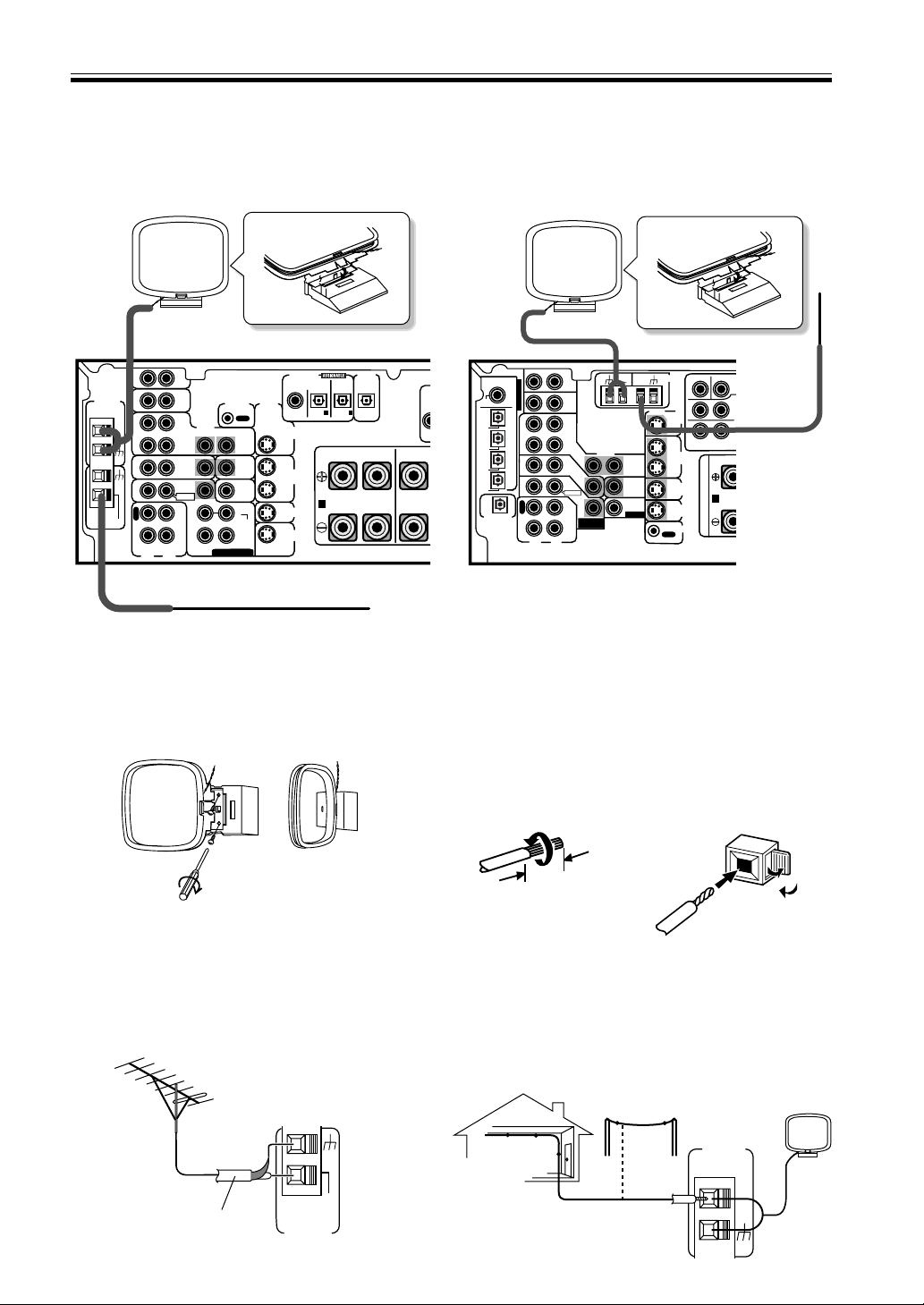
Connecting Antennas
Connect the AM loop antenna and the FM wire antenna as shown below. To improve reception and sound quality,
connect external antennas (see Using external antennas, below). Always make sure that the receiver is switched off
and unplugged from the wall outlet before making or changing any connections.
Connecting Your Equipment
LR
LR
RL
S
FRONT CENTER
DIGITAL IN
PCM/2/DTS
DIGITAL
OUT
TO
MONTOR
TV
TO
MONTOR
TV
VCR /
DVR
VIDEO
VIDEO
VCR /
DVR
CONTROL
IN
AUX
CD
IN
OUT
IN
IN OUT
OUT
CD - R
/ TAPE
/ MD
SURROUND
CENTER
SUB W.
SUB W.
PREOUT
IN
IN
IN
Y
S
IN
S
IN
S
OUT
S
OUT
IN
IN
IN
TV /
SAT
TV /
SAT
DVD/
LD
DVD
/ LD
FRONT
(DVD) (CD) (CD-R)
COAX OPT OPT OPT
R
E
C
P
L
A
Y
A
1 2
OUT
FM
UNBAL75Ω
ANTENNA
AM
LOOP
DVD 5.1 CH INPUT
VSX-D710S
L
R
R
R
L
L
BAC
LR
VIDEO
VIDEO
COMPONENT
VIDEO
TO
MONTOR
TV
TO
MONTOR
TV OUT
VCR /
DVR
DIGITAL IN
TO MONITOR TV OUT
CENTER
SUB WOOFER
SURROUND
SURROUND BACK
CONTROL
IN
IN
IN
AUX
IN
CD
IN
(DVD)
(CD)
PCM/
2
/DTS
C
O
A
X
O
P
T
¥
O
P
T
ø
O
P
T
π
O
P
T
[
O
P
T
IN
IN
IN
OUT
OUT
CD - R
/ TAPE
/ MD
SUB
WOOFER
DIGITAL OUT
Y
Y
P
B
P
R
IN
TV /
SAT
TV /
SAT
DVD
/ LD
DVD/
LD
FRONT
O
U
T
R
E
C
P
L
A
Y
A
(
DV
(T
V
VCR /
DVR
S
IN
S
IN
S
IN
S
OUT
S
OUT
PREOUT
(TV)
(VCR)
(CD-R)
OUT
FM
UNBAL
75Ω
AM
LOOP
ANTENNA
DVD 7.1 CH
INPUT
DVD
7.1 CH
INPUT
FRONT CENTER
PREOUT
ASSIGNABLE
S
P
E
A
K
E
R
S
VSX-D810S/D850S
FM wire antenna
Connect the FM wire antenna and fully extend vertically
along a window frame or other suitable area, etc.
AM loop antenna
Assemble the antenna and connect to the receiver.
Attach to a wall, etc. (if desired) and face in the
direction that gives the best reception.
Antenna snap connectors
Twist the exposed wire strands together and insert into
the hole, then snap the connector shut.
3/8 in. (10mm)
To improve FM reception
Connect an external FM antenna.
FM
UNBAL
75Ω
FM
ANTENNA
AM LOOP
ANTENNA
To improve AM reception
Connect a 15-18 feet length of vinyl-coated wire to the AM
antenna terminal without disconnecting the supplied AM loop
antenna.
For the best possible reception, suspend horizontally outdoors.
Outdoor antenna
15-18 ft. (5–6m)
Indoor antenna
(Vinyl-coated wire)
75 Ω coaxial cable
Using External Antennas
VSX-D710S
VSX-D710S
12
En
Connecting Your Equipment
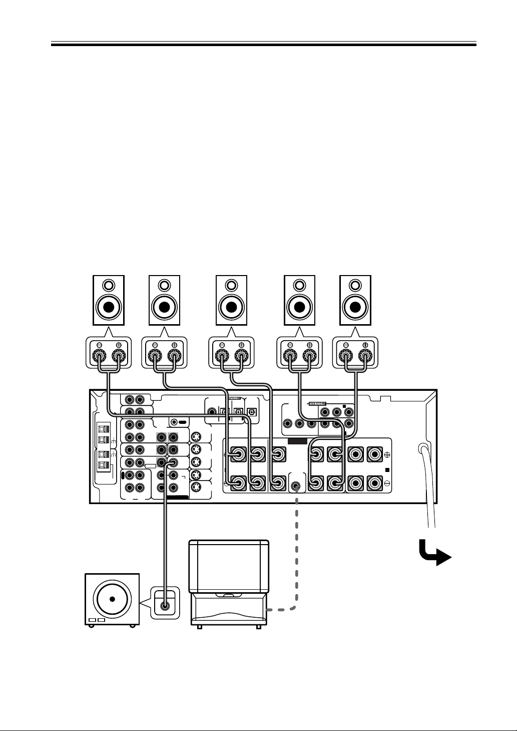
Connecting Speakers (VSX-D710S)
A full complement of six speakers is shown here but, naturally, everyone’s home setup will vary. Simply connect the
speakers you have in the manner described below. The receiver will work with just two stereo speakers (called “front”
speakers in the diagram) but we recommend you use at least three speakers and five is best.
Make sure you connect the speaker on the right to the right terminal and the speaker on the left to the left terminal.
Also make sure the positive and negative (+/–) terminals on the receiver match those on the speakers.
MEMO:
• The receiver has two speaker systems, A & B. A is the main system supporting the full complement of surround
sound speakers. If you switch on both A & B speaker systems, only front speakers and the subwoofer will
be audible. No sound will come from the center or surround speakers but multi channel sources will be
down-mixed to the active speakers so no sound will be lost. Similarly, if you choose just the B system you‘ll only
hear the front speakers connected to the B system and multi channel sources will be down-mixed to these two
speakers.
• Use speakers with a nominal impedance of 8 Ω to 16 Ω.
Be sure to complete all other
connections before connecting this
unit to the AC power source.
Front Speakers (A)
Center Speaker
SURROUND Speakers
Powered
subwoofer
LR
C
SR
SL
When using the speaker on your TV as the center
speaker (‘C’), connect the CENTER PREOUT jack on this
unit to the audio input jack on your TV. In this case, the
center speaker shown is unnecessary.
LR
LR
RL
S
FRONT
LR
FRONT
LR
SURROUNDCENTER
COMPONENT
VIDEO
DIGITAL IN
PCM/2/DTS
DIGITAL
OUT
TO
MONTOR
TV
TO
MONTOR
TV
VCR /
DVR
VIDEO
VIDEO
VCR /
DVR
TO MONITOR TV OUT
CONTROL
IN
AUX
CD
IN
OUT
IN
IN OUT
OUT
CD - R
/ TAPE
/ MD
SURROUND
CENTER
SUB W.
SUB W.
PREOUT
IN
IN
IN
YP
B
P
R
YP
B
P
R
S
IN
S
IN
S
OUT
S
OUT
IN
IN
IN
TV /
SAT
TV /
SAT
DVD/
LD
DVD
/ LD
FRONT
CENTER
PREOUT
(DVD) (CD) (CD-R)
COAX OPT OPT OPT
R
E
C
P
L
A
Y
A B
1 2
1
(TV/SAT) IN
(DVD/LD) IN
2
OUT
FM
UNBAL75Ω
ANTENNA
AM
LOOP
DVD 5.1 CH INPUT
SPEAKERS
INPUT
VSX-D710S
13
En
Connecting Your Equipment
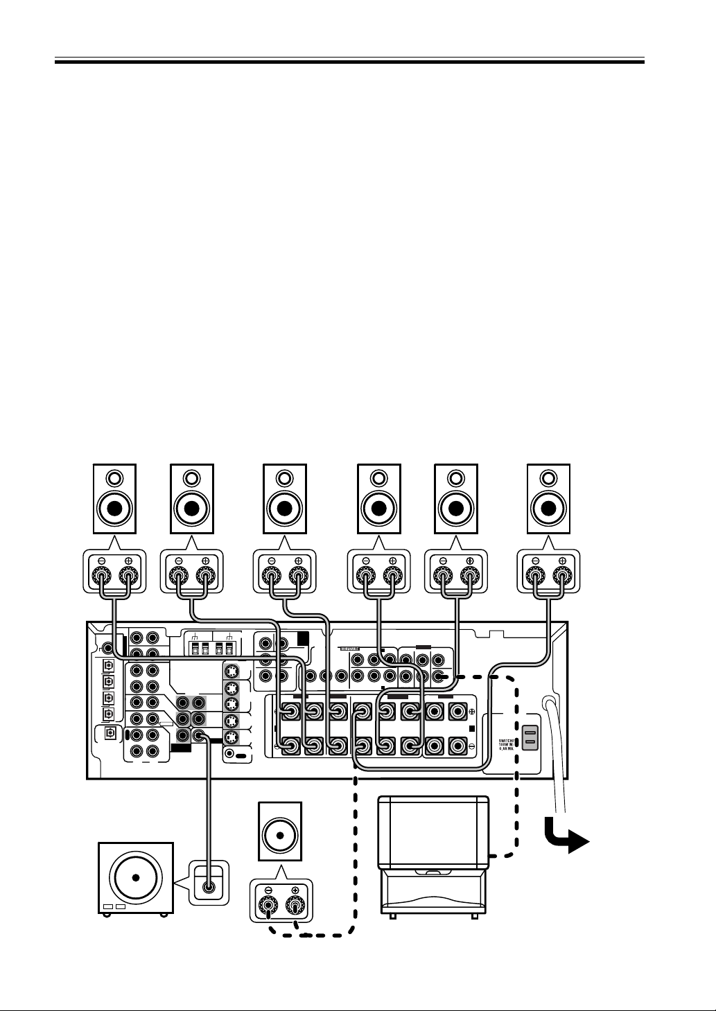
Connecting Speakers (VSX-D810S/D850S)
A full complement of seven speakers is shown here but, naturally, everyone’s home setup will vary. Simply connect
the speakers you have in the manner described below. The receiver will work with just two stereo speakers (called
“front” speakers in the diagram) but we recommend you use at least three speakers. To get the most out of the VSX-
D810S/D850S models hook up all seven speakers, including a surround back speaker, the latest advancement in
home theater. You can only hook up one speaker here as the surround back channel is mono on the VSX-D810S/
D850S models. This is actually 6.1 ch sound but we usually refer to it by its regular name, 7.1 ch sound. The two are
essentially the same thing both offering surround back sound. If you don’t hook up a surround back speaker you can
use that speaker terminal to hook up your subwoofer.
Make sure you connect the speaker on the right to the right terminal and the speaker on the left to the left terminal.
Also make sure the positive and negative (+/–) terminals on the receiver match those on the speakers.
MEMO:
• The receiver has two speaker systems, A & B. A is the main system supporting the full complement of surround
sound speakers. If you switch on both A & B speaker systems, only front speakers and the subwoofer will be
audible. No sound will come from the center or surround speakers but multi channel sources will be down-
mixed to the active speakers so no sound will be lost. Similarly, if you choose just the B system you‘ll only hear the
front speakers connected to the B system and multi channel sources will be down-mixed to these two speakers.
• Use speakers with a nominal impedance of 8 Ω to 16 Ω.
• If you select subwoofer (SB SUBWF) in the surround back speakers setting mode (see p.17) you can hook a
subwoofer up to the surround back speaker terminals. In this case the terminals will be used for this “passive
subwoofer” and no surround back sound will come from these terminals.
Be sure to complete all
other connections before
connecting this unit to
the AC power source.
Front Speakers (A)
Center Speaker
SURROUND Speakers
Powered subwoofer
LR
C
SR
SL
When using the speaker on your TV as the center
speaker (‘C’), connect the CENTER PREOUT jack on this
unit to the audio input jack on your TV. In this case, the
center speaker shown is unnecessary.
L
R
R
R
L
L
L
R
L
R
BACK
LR
VIDEO
AC OUTLET
VIDEO
COMPONENT
VIDEO
FRONT
CENTER
SURROUND
SURROUND
BACK
TO
MONTOR
TV
TO
MONTOR
TV OUT
VCR /
DVR
DIGITAL IN
TO MONITOR TV OUT
CENTER
SUB WOOFER
SURROUND
SURROUND BACK
CONTROL
IN
IN
IN
AUX
IN
CD
IN
(DVD)
(CD)
PCM/
2
/DTS
C
O
A
X
O
P
T
¥
O
P
T
ø
O
P
T
π
O
P
T
[
O
P
T
IN
IN
IN
OUT
OUT
CD - R
/ TAPE
/ MD
SUB
WOOFER
DIGITAL OUT
Y
Y
L
R
L
R
P
B
P
B
P
R
P
R
IN
TV /
SAT
TV /
SAT
DVD
/ LD
DVD/
LD
FRONT
O
U
T
R
E
C
P
L
A
Y
A
(DVD/LD) IN
1
(TV/SAT) IN
2
B
VCR /
DVR
S
IN
S
IN
S
IN
S
OUT
S
OUT
PREOUT
(TV)
(VCR)
(CD-R)
OUT
FM
UNBAL
75Ω
AM
LOOP
ANTENNA
DVD 7.1 CH
INPUT
DVD
7.1 CH
INPUT
PREOUT
FRONT FRONT
SURROUND
CENTER
PREOUT
ASSIGNABLE
S
P
E
A
K
E
R
S
INPUT
VSX-D810S/D850S
SURROUND BACK Speaker
SB
Subwoofer (passive)
14
En
Connecting Your Equipment
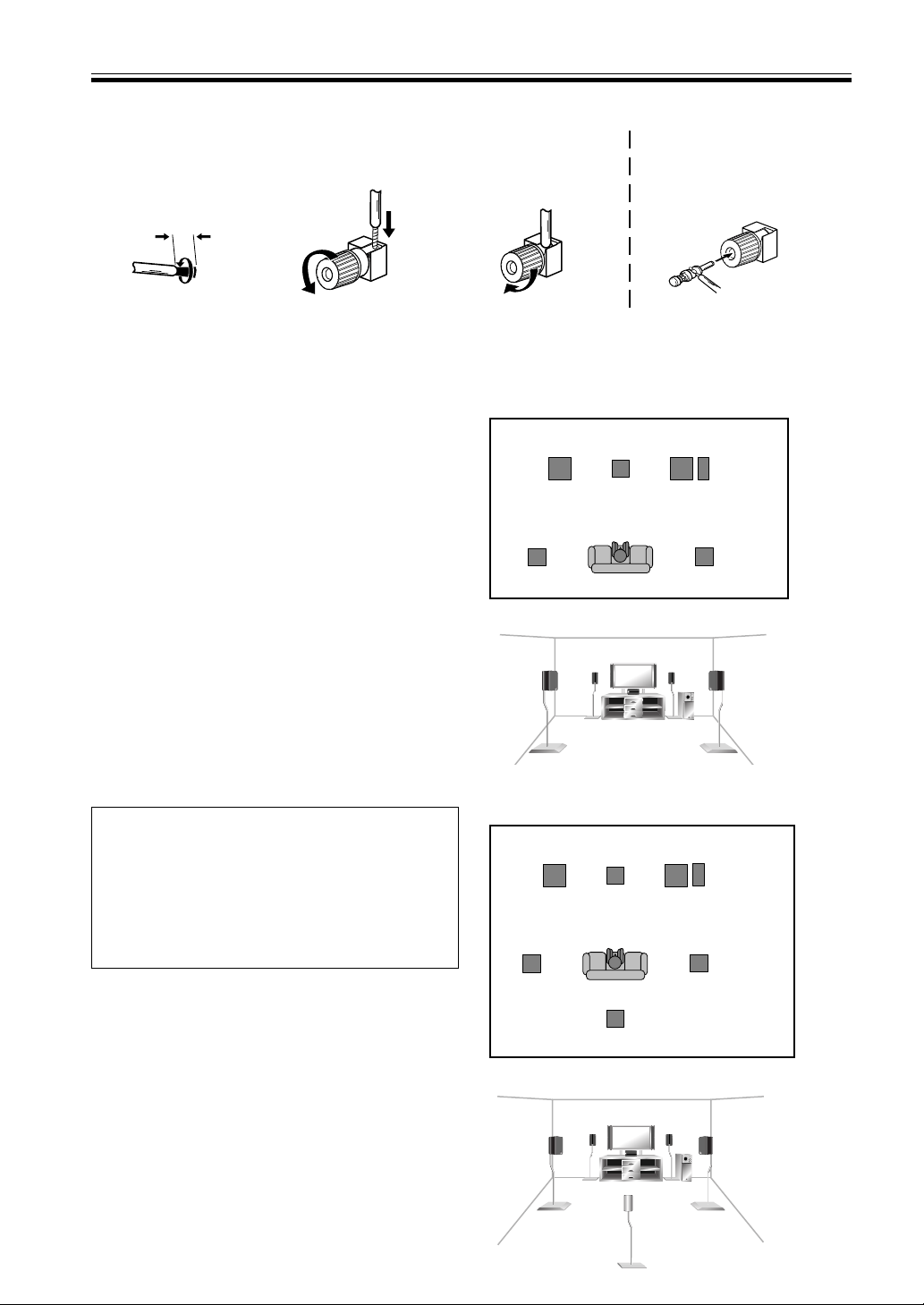
1 Twist exposed wire
strands together.
2 Loosen speaker terminal
and insert exposed wire.
3 Tighten terminal.
Speaker terminals
3/8 in. (10mm)
Hints on Speaker Placement
Speakers are usually designed with a particular place-
ment in mind. Some are designed to be floor standing,
while others should be placed on stands to sound their
best. Some should be placed near a wall; others should
be placed away from walls. Follow the guidelines on
placement that the speaker manufacturer provided with
your particular speakers to get the most out of them.
• Place the front left and right speakers at equal
To achieve the best possible surround sound, install your
speakers as shown on the right. Be sure all speakers are
installed securely to prevent accidents and improve
sound quality.
distances from the TV.
• When placing speakers near the TV, we recommend
using magnetically shielded speakers to prevent
possible interference, such as discoloration of the
picture when the TV is switched on. If you do not
have magnetically shielded speakers and notice
discoloration of the TV picture, move the speakers
farther away from the TV.
• Install the center speaker above or below the TV so
that the sound of the center channel is localized at
the TV screen.
CAUTION!
If you choose to install the center speaker on top
of the TV, be sure to secure it with putty, or by
other suitable means, to reduce the risk of damage
or injury resulting from the speaker falling from
the TV in the event of external shocks such as
earthquakes.
• If possible, install the surround speakers slightly
above ear level.
• Try not to install the surround speakers farther away
from the listening position than the front and center
speakers. Doing so can weaken the surround sound
effect.
Overhead view of speaker set up ~VSX-D710S~
3-D view of speaker set up
Surround Left
Surround Right
Listening Position
Front
Left
Front
Right
Center
Subwoofer
Overhead view of speaker set up ~VSX-D810S/D850S~
3-D view of speaker set up
Surround Left
Surround Right
Listening Position
Front
Left
Front
Right
Center
Subwoofer
Surround Back
Caution:
Make sure that all the bare speaker wire is twisted together and inserted fully into the speaker terminal. If
any of the bare speaker wire touches the back panel it may cause the power to cut off as a safety measure.
The speaker terminals also
accept single banana plugs.
(Refer to speaker manual for
details.)
15
En
Connecting Your Equipment
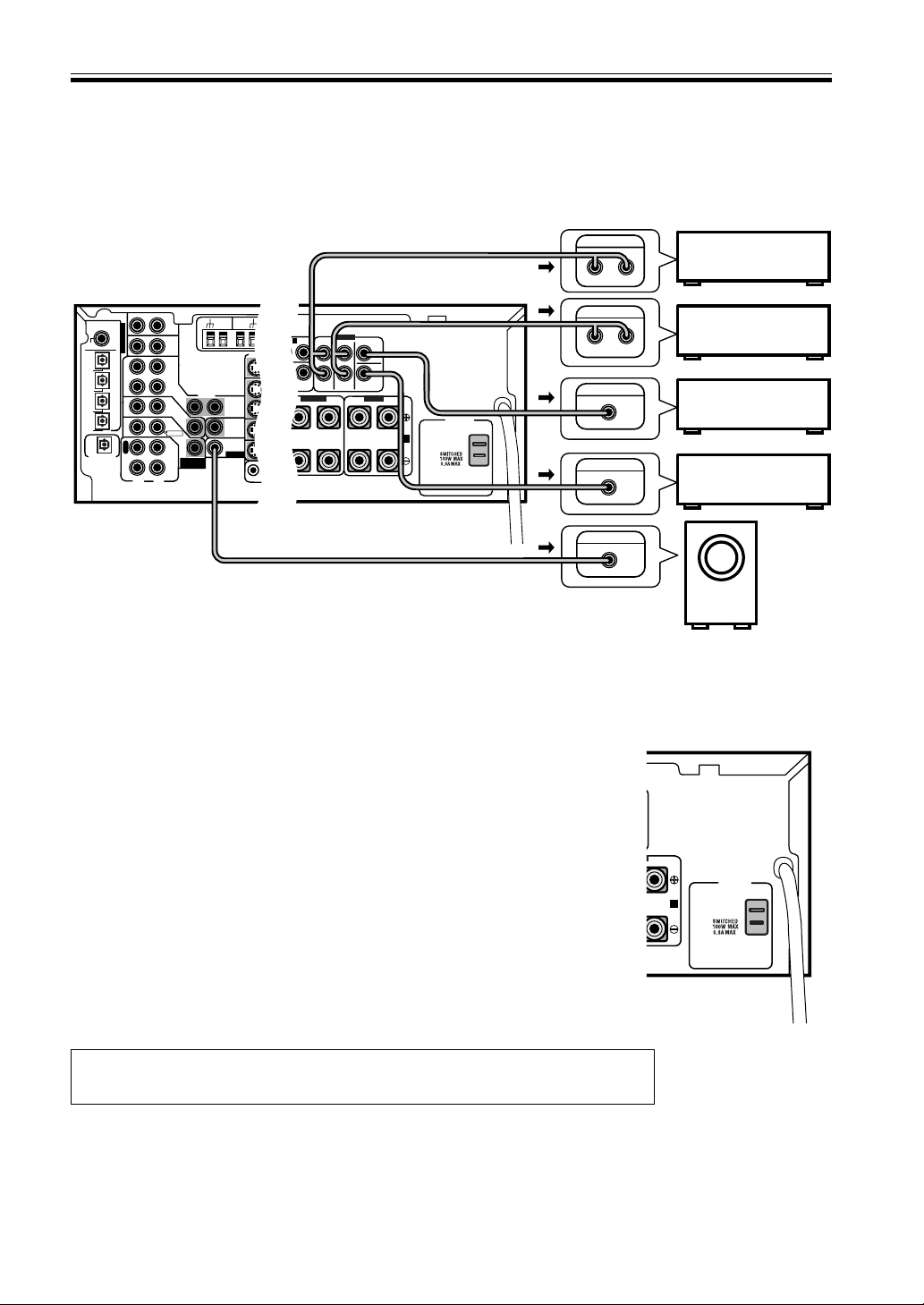
AC Outlet [switched 100 W (0.8 A) max]
Power supplied through this outlet is turned on and off by the receiver's POWER
switch.
Total electrical power consumption of connected equipment should not exceed
100 W (0.8 A).
CAUTION
Do not connect a heater, TV, etc. Also, make sure no exposed speaker wire is
touching the rear panel, this may cause the receiver to turn off automatically.
MEMO:
• This unit should be disconnected by removing the power plug from the wall
socket when not in regular use, e.g., on vacation.
• Do not connect appliances with high power consumption such as heaters,
irons, or television sets to this AC OUTLET in order to avoid overheating and
fire risk. This can also cause the receiver to malfunction.
CAUTION:
DO NOT CONNECT A MONITOR OR TV SET TO THIS UNIT'S AC OUTLET.
L
AC OUTLET
B
Connecting Additional Amplifiers (VSX-D810S/D850S only)
This receiver has more than sufficient power for any home use, however it is possible to add additional amplifiers to
every channel. Make the connections shown below to add amplifiers to power your speakers. Always make sure that
the receiver is switched off and unplugged from the wall outlet before making or changing any connections.
L
R
R
R
L
L
L
R
L
R
BACK
AC OUTLET
VIDEO
COMPONENT
VIDEO
FRONT
CENTER
SURROUND
SURROUND
BACK
TO
MONTOR
TV
TO
MONTOR
TV OUT
TO MONITOR TV OUT
CENTER
SUB WOOFER
SURROUND
SURROUND BACK
CONTROL
OUT
SUB
WOOFER
Y
Y
L
R
L
R
P
B
P
B
P
R
P
R
TV /
SAT
DVD/
LD
A
(DVD/LD) IN
1
(TV/SAT) IN
2
B
VCR /
DVR
S
IN
S
IN
S
IN
S
OUT
S
OUT
PREOUT
OUT
FM
UNBAL
75Ω
AM
LOOP
ANTENNA
DVD
7.1 CH
INPUT
PREOUT
FRONT FRONT
SURROUND
CENTER
PREOUT
S
P
E
A
K
E
R
S
ANALOG IN
ANALOG IN
ANALOG IN
INPUT
ANALOG IN
LR
LR
LR
VIDEO
VIDEO
TO
MONTOR
TV
TO
MONTOR
TV OUT
VCR /
DVR
DIGITAL IN
CONTROL
IN
IN
IN
AUX
IN
CD
IN
(DVD)
(CD)
PCM/
2
/DTS
C
O
A
X
O
P
T
¥
O
P
T
ø
O
P
T
π
O
P
T
[
O
P
T
IN
IN
IN
OUT
OUT
CD - R
/ TAPE
/ MD
SUB
WOOFER
DIGITAL OUT
IN
TV /
SAT
TV /
SAT
DVD
/ LD
DVD/
LD
FRONT
O
U
T
R
E
C
P
L
A
Y
VCR /
DVR
S
IN
S
IN
S
IN
S
OUT
S
OUT
PREOUT
(TV)
(VCR)
(CD-R)
OUT
FM
UNBAL
75Ω
AM
LOOP
ANTENNA
DVD 7.1 CH
INPUT
PREOUT
ASSIGNABLE
VSX-D810S/D850S
Front channel
amplifier
Surround channel
amplifier
Surround Back
channel amplifier
Center channel
amplifier
Powered
Subwoofer
MEMO:
To hear sound only from the pre-outs, disconnect any speakers that are connected
directly to the receiver. (Using the SPEAKERS button to switch off the speakers also
mutes the pre-outs; you must set it to either A, B, or A+B.)
The arrows indicate the direction of the audio signal.
POWER-CORD CAUTION
Handle the power cord by the plug. Do not pull out the plug by tugging the cord and never touch the power cord
when your hands are wet as this could cause a short circuit or electric shock. Do not place the unit, a piece of
furniture, etc., on the power cord, or pinch the cord. Never make a knot in the cord or tie it with other cords. The
power cords should be routed such that they are not likely to be stepped on. A damaged power cord can cause a fire
or give you an electrical shock. Check the power cord once in a while. When you find it damaged, ask your nearest
PIONEER authorized service center or your dealer for a replacement.
16
En
04
Preparations
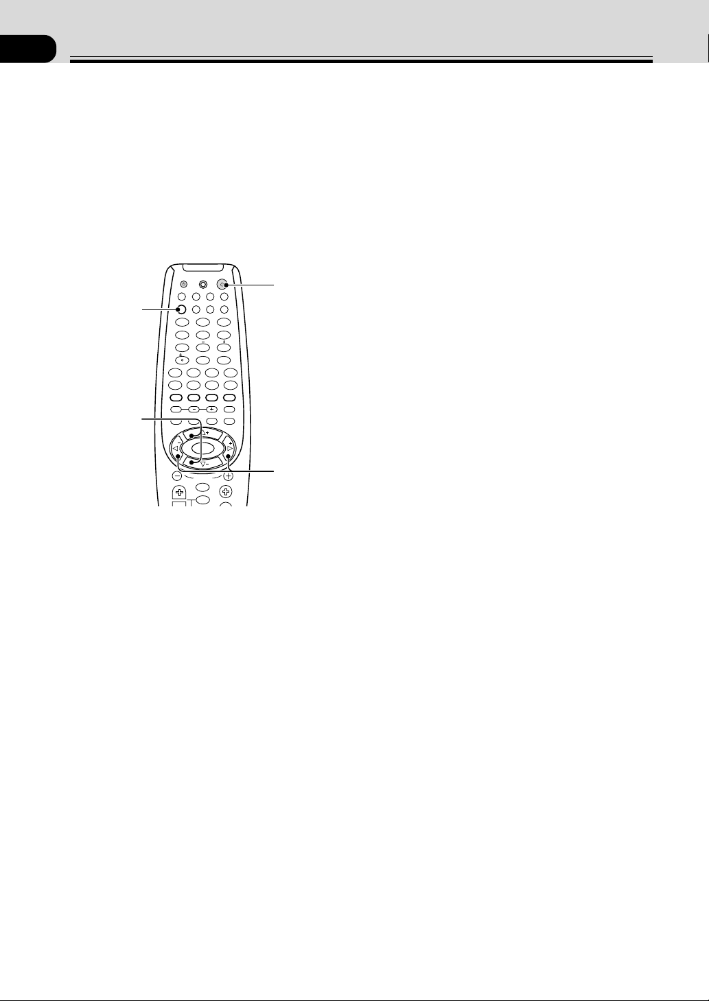
1 Press RECEIVER to turn the power on.
The STANDBY indicator goes out.
2 Press RCV.
This button switches the remote to the receiver’s
surround setup mode.
3 Press @ or # to select the mode you want to
set.
For best results, start with “SPEAKERS setting mode”
and make your initial adjustments in the order
described below.
The current settings are displayed automatically.
• DTS-ES ON/OFF setting mode (page 17) (VSX-
D810S/D850S only)
Use to turn the DTS-ES (surround back) channels
ON or OFF (for DTS discs only).
• SPEAKERS (Front, Center, Surround) setting
mode (page 17)
Use to specify the size and type of speakers you have
connected.
• SPEAKERS (Surround Back) setting mode (page
17) (VSX-D810S/D850S only)
Use to specify the size and type of surround back
speaker you have connected or if you have con-
nected a subwoofer here.
•
SUBWOOFER ON/PLUS/OFF setting mode (page 18)
Use to specify if the subwoofer is set to on, plus or off.
• Crossover frequency setting mode (page 18)
Use to determine which frequencies will be sent to
the subwoofer (or “Large” speakers if you don’t have
a subwoofer).
Setting Up for Surround Sound
Be sure to switch the power of this unit on (The
STANDBY indicator goes out).
To ensure the best possible surround sound, be sure to
complete the following set up operations. This is
particularly important when using the 2 (Dolby)/DTS
surround mode. You only need to make these settings
once (unless you change the placement of your current
speaker system or add new speakers, etc.). Refer to the
following pages for detailed descriptions of the settings
available for each mode.
• LFE attenuator setting mode (page 18)
Use to specify the peak level for the LFE channel and
the crossover network for rerouted bass frequencies.
• Low cut filter ON/OFF setting mode (page 18)
Use to cut the distorted sound from the subwoofer.
• FRONT speakers distance setting mode (page 18)
Use to specify the distance from your listening
position to your front speaker.
• CENTER speakers distance setting mode (page 18)
Use to specify the distance from your listening
position to your center speaker.
• SURROUND speakers distance setting mode (page
19)
Use to specify the distance from your listening
position to your surround speakers.
• SURROUND BACK speakers distance setting
mode (VSX-D810S/D850S only) (page 19)
Use to specify the distance from your listening
position to your surround back speaker.
• Dynamic range control setting mode (page 19)
Use to compress the dynamic range of the sound track.
• Dual mono setting mode (page 19)
Use with 2 Digital software that has dual mono
encoding if you want to isolate one channel or listen
in this specialized mono mode.
• Component input 1 setting (page 20)
Use to specify the video component connected to this
input.
• Component input 2 setting (page 20)
Use to specify the video component connected to this
input.
• Multi Channel External Decoder Surround Back
1ch/2ch setting (VSX-D810S/D850S only) (page 20)
Use to specify whether you hooked up your External
Multi Channel Decoder surround back speaker
connection with one or two cords. If you’re not using
a External Multi Channel Decoder ignore this setting.
• Coaxial digital input setting (page 20)
Use to specify the input to be assigned to the coaxial
digital input.
• Optical digital input 1 setting (page 20)
Use to specify the input assigned to this optical digital
input.
• Optical digital input 2 setting (page 20)
Use to specify the input assigned to this optical digital
input.
• Optical digital input 3 setting (VSX-D810S/D850S
only) (page 20)
Use to specify the input assigned to this optical digital
input.
• Optical digital input 4 setting (VSX-D850S only)
(page 21)
Use to specify the input assigned to this optical digital
input.
4 Press % or fi to select the setting you want.
The setting is entered automatically.
5 Repeat steps 3 and 4 to set other surround
modes.
MEMO:
Press ENTER to exit the setting mode.
The setting mode is automatically exited if no operation
is performed within 20 seconds.
TVFUNC
MENU
VOLUME
MASTER VOLUME
CHANNEL
ENTER
ENTER
DISC
DTV INFO
MPX/RETURN
DTV ON/OFF DTV MENU
D.ACCESS GUIDE
ST
TUNE
TUNE
ST
CLASS
ATT
BAND
/DTS DSP
TEST TONE
CH SELECT CH LEVEL FUNCTION
SIGNAL SELECT
1¡
4
¢
7
8
3
EFFECT
DVD VCR CD-RTV
RCV
TUN
TVC
CD
MIDNIGHT
LOUDNESS
MUTING
SETUP
FL DIMMER
MULTI CONTROL
5.1 / 7.1
RECEIVER
SOURCE
1
2
3
4
5
6
7
8
9
0
10
2
1
2
3
4
17
En
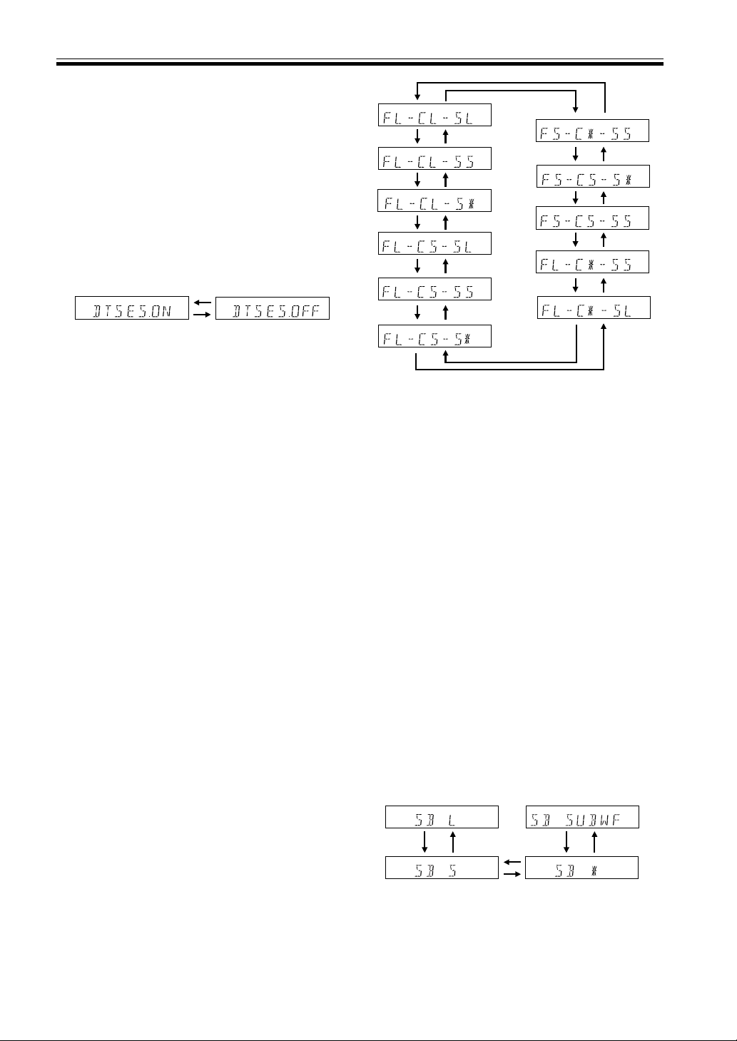
SPEAKERS (Front, Center, Surround)
setting mode
This setting establishes the size and configuration of the
speaker system you have connected. So, for example,
here you set whether you have connected surround
speakers or not, and how big they are. Selecting “Large”
or “Small” will determine how much bass is sent by the
receiver to the speakers being set.
In the display, “F”, “C”, and “S” refer to front, center,
and surround speakers respectively. Speaker size is
denoted as “L” for large speakers, “S” for small
speakers, and “
*
” (asterisk) if no speaker is connected.
Choose a speaker setting mode according to
the speakers you hooked up. Use the % or fi
buttons.
The configurations shown below will appear in the
display on the front of the receiver. One of them
should match your speaker set up. Cycle through the
different possibilities until you find the one that
matches your set up.
Press # to advance to the next receiver setting, and
press @ to return to a previous receiver setting.
Preparations
SPEAKERS (Surround Back) setting
mode (VSX-D810S/D850S only)
This setting establishes the size of the speaker connected
to the surround back terminal (VSX-D810S/D850S only).
You can choose a surround back speaker and its size or
you can choose to hook a subwoofer to this terminal.
Switch the surround back speaker setting
mode according to the size of the speaker
you hooked up. Use the % or fi buttons.
The configurations shown below will appear in the
display on the front of the receiver. Choose one.
Cycle through the different possibilities until you find
the one that matches your set up.
If you select SB SUBWF here you can hook a
subwoofer up to the surround back speaker terminals
(see p.13). In this case the terminals will be used for
this “passive subwoofer” and no surround back
sound will come from these terminals.
Press # to advance to the next receiver setting, and
press @ to return to a previous receiver setting.
MEMO:
If the cone size (diameter) of the speaker is larger than 5
inches, please set to Large.
MEMO:
• You can only set the surround back speaker to large if
the surround speakers are set to small.
• If you choose none for surround speakers (see
previous setup) you won’t be able to select any
surround back speakers either.
• If you choose A+B speaker systems no sound is heard
from the “passive subwoofer”.
DTS-ES ON/OFF setting mode (VSX-
D810S/D850S only)
This setting allows you to hear surround back channels
on DTS disc regardless of whether the disc itself is a 5.1
Ch disc or a 6.1 Ch disc. Naturally you need to hook up
surround back speakers (see p. 13) and set them properly
(see below on this page) in order to hear surround back
channels. If you choose ON you will hear surround back
channels with DTS discs. If you choose OFF you will not.
Choose DTS-ES ON or OFF by using the %
or fi buttons.
MEMO:
• If you choose none for the surround back speakers setting
later on this page you won’t be able to select ON here.
• You’ll only get surround back channel sound when
the receiver is in STANDARD mode (see p. 27-29),
DTS-ES is set to ON and the disc is a DTS 5.1/6.1
channel disc.

18
En
Preparations
Crossover frequency setting mode
Crossover frequency is the point where the receiver
divides the high and low sounds (the frequencies)
between the speakers. Since most smaller speakers can’t
handle deep bass tones, this setting allows you to send
those sounds to the subwoofer (or speakers set to
“Large” if you don’t have a subwoofer) instead of the
speakers set to “Small” in your system. Choose the point
at which you want the frequency routed to the
subwoofer (or “Large” speakers).
We recommend setting this to 200 Hz if smaller
bookshelf-type speakers are used for your “Small”
speakers.
Press % or fi to specify the crossover
frequency for your small speakers (100 Hz,
150 Hz or 200 Hz).
150Hz100Hz
200Hz
100 Hz
Sends bass frequencies below 100 Hz to the subwoofer
(or “Large” speakers).
150 Hz
Sends bass frequencies below 150 Hz to the subwoofer
(or “Large” speakers).
200 Hz
Sends bass frequencies below 200 Hz to the subwoofer
(or “Large” speakers).
MEMO:
• The initial setting is “100 Hz”.
• If all speakers (front, center, and surround) are set to
“Large” in SPEAKERS setting mode, crossover
frequency cannot be set because there are no “Small”
speakers (
***
appears in the display).
LFE attenuator setting mode
Dolby Digital and DTS audio sources include ultra-low
bass tones. Set the LFE attenuator as needed to prevent
the ultra-low bass tones from distorting the sound from
the speakers.
Press % or fi to set the attenuation level (0
dB, 10 dB or
**
dB(∞)).
MEMO:
• The initial setting is “
0 dB”.
• When ∞ is selected (
**
appears in the display), LFE
is not available.
Low cut filter ON/OFF setting mode
Turn the low cut filter ON when distorted sound is
output through the subwoofer.
Press % or fi to select low cut filter ON or
OFF.
MEMO:
• The initial setting is “
OFF”.
• If the SUBWOOFER is set to “OFF” in the
SUBWOOFER ON/OFF setting mode, the low cut
filter cannot be set.
FRONT speakers distance setting mode
Sets the distance from the FRONT speakers to the
listening position.
Press % or fi to set the distance of the
FRONT speakers from the main listening
position (within a 30 foot range).
MEMO:
• The initial setting is 10 ft.
• One step equals about 1ft.
CENTER speaker distance setting mode
Sets the distance from the CENTER speakers to the
listening position.
Press % or fi to set the distance of the
CENTER speaker from the main listening
position (within a 30 foot range).
MEMO:
• The initial setting is 10 ft.
• When “
C
*
” is selected in SPEAKERS setting mode,
the Center distance cannot be set.
• One step equals about 1 ft.
10 dB0 dB
∞ (display "
**
")
SUBWOOFER ON/PLUS/OFF setting
mode
Sets whether the SUBWOOFER is used or not. Also, when
used you have the option to use the “PLUS” setting.
Press % or fi to select subwoofer ON, PLUS
or OFF.
MEMO:
• The initial setting is “
ON”.
• Setting the front speaker size to “Small” in the
SPEAKERS setting mode automatically locks the
subwoofer in the “ON” position.
• Use the PLUS for extra bass. When you use PLUS
you will get the bass sounds from the subwoofer
even if the front speakers are set to “Large”.
• If you select “OFF” in this setting you won’t be able to
select subwoofer in the surround back speaker
setting above.

19
En
Preparations
SURROUND speakers distance
setting mode
Use to set the SURROUND speakers distance. Like the
CENTER speaker position, the SURROUND speakers
may be set in a location closer or farther to your main
listening position than the FRONT speakers. Set the
distance of the SURROUND speakers accurately to hear
sounds coming from both FRONT and SURROUND
speakers at the same time.
Press % or fi to set the distance of the
SURROUND speakers from the main
listening position (within a 30 foot range).
MEMO:
• The initial setting is 10 ft.
• When “S
*
” is selected in SPEAKERS setting mode,
the SURROUND distance cannot be set.
• One step equals about 1 ft.
SURROUND BACK speaker distance
setting mode (VSX-D810S/D850S
only)
Use to set the SURROUND back speaker distance. Like
the SURROUND speakers, the SURROUND BACK
speakers may be set in a location closer or farther to
your main listening position than the FRONT speakers.
Set the distance of the SURROUND speakers accurately
to hear sounds coming from both FRONT and
SURROUND speakers at the same time.
Press % or fi to set the distance of the
SURROUND speakers from the main
listening position (within a 30 foot range).
MEMO:
• The initial setting is 10 ft.
• When “
SB
*
” is selected in SPEAKERS setting mode,
the SURROUND BACK distance cannot be set.
• One step equals about 1 ft.
Dual mono setting
The dual mono setting can only be used when listening to
Dolby Digital discs that have dual mono software encoded
in them. As of now these are not that widely used. With
this setting you can choose which channel in the dual
mono setting you want to listen to. Thus, it is useful for
soundtracks that have one language on one channel and a
different language on the other. Remember you can only
use this setting if you have Dolby Digital software with this
feature and want to isolate one of the channels therein.
There are two different ways to route the sound in the dual
mono setting, one is with Dolby Digital mode on, the other
with Dolby Digital mode off. If Dolby Digital mode is
switched on, the ch1 setting will play channel 1 through
your center speaker. The ch2 setting will play channel 2
through your center speaker. With Dolby Digital mode off,
the dual mono sound routing is as follows: In the
ch1
setting your will hear channel 1 out of both front speakers.
In the ch2 setting you will hear channel 2 out of both
speakers. In the
L. c1 R. c2 setting the speakers will play
the soundtrack independently of each other. The left front
speaker will play channel 1 and the right front speaker will
play channel 2.
Press % or fi to cycle through the possible
DUAL MONO settings.
ch1ch2
L. c 1 R. c 2
MEMO:
• The default setting of this feature is
ch1.
Dynamic range control setting mode
Dynamic range is the difference between the loudest and
softest sounds in any given signal. The dynamic range
control helps you play back sounds so the quieter sounds
are audible yet the louder sounds don’t get distorted. It
does this by compressing the dynamic range. When
watching a movie at low volume, setting this function
enables low level sounds to be heard more easily but you
won’t be jolted by louder sounds.
Press % or fi to set the dynamic range control
(OFF, MAX, or MID).
MEMO:
• The initial setting is “OFF”.
• When the volume level is increased, set to OFF.
• For listening enjoyment at low volumes, set to “MAX”
for maximum dynamic range compression.
• Dynamic range control is effective only when a Dolby
Digital signal is being played back.

20
En
Component input 1 setting
Tells the receiver What (DVD player, etc.) is connected to
this input.
Press % or fi to select the component setting
(DVD, TV, VCR or OFF).
MEMO:
• The initial setting is “DVD”.
Component input 2 setting
Tells the receiver What (TV, player etc.) is connected to
this input.
Press % or fi to select the component setting
(TV, VCR, OFF or DVD).
MEMO:
• The initial setting is “
TV”.
Multi Channel External Decoder
Surround Back 1ch/2ch setting (VSX-
D810S/VSX-D850S only)
You only need to make this setting if you are using a
multi channel external decoder with your DVD player. If
you aren’t just ignore this setting.
Press % or fi to select the channel setting.
Select 1ch if your DVD is outputting 6.1
sound (the surround back channel is mono)
or select 2ch if your DVD is outputting 7.1
sound (the surround back channel is stereo).
Coaxial digital input setting
Here you tell the receiver what component you have
hooked up to the coaxial digital input jack.
Press % or fi to select the coaxial digital
input (DVD, TV, CD, CD-R, VCR, or OFF).
After you assign the component to this digital jack
whenever you select that component, for example a
CD player, the receiver will automatically change to
the digital input setting. You can see this in the
DIGITAL/ANALOG indicator on the front of the
receiver.
MEMO:
• The initial setting is “DVD”.
Optical digital input 1 setting
Here you tell the receiver what component you have
hooked up to the optical input jack 1.
Press % or fi to select the optical digital
input 1 (DVD, TV, CD, CD-R, VCR, or OFF).
After you assign a component to this digital jack
whenever you select that component, for example a
CD player, the receiver will automatically change to
the digital input setting. You can see this in the
DIGITAL/ANALOG indicator on the front of the
receiver.
MEMO:
• The initial setting is “CD”.
Optical digital input 2 setting
Here you tell the receiver what component you have
hooked up to the optical input jack 2.
Press % or fi to select the optical digital
input 2 (DVD, TV, CD, CD-R, VCR, or OFF).
After you assign a component to this digital jack
whenever you select that component, for example a
CD player, the receiver will automatically change to
the digital input setting. You can see this in the
DIGITAL/ANALOG indicator on the front of the
receiver.
MEMO:
• The initial setting is “CD-R”.
Optical digital input 3 setting (VSX-
D810S/VSX-D850S only)
Here you tell the receiver what component you have
hooked up to the optical input jack 3.
Press % or fi to select the optical digital
input 2 (DVD, TV, CD, CD-R, VCR, or OFF).
After you assign a component to this digital jack,
whenever you select that component, for example a
CD player, the receiver will automatically change to
the digital input setting. You can see this in the
DIGITAL/ANALOG indicator on the front of the
receiver.
MEMO:
• The initial setting is “TV”.
Preparations
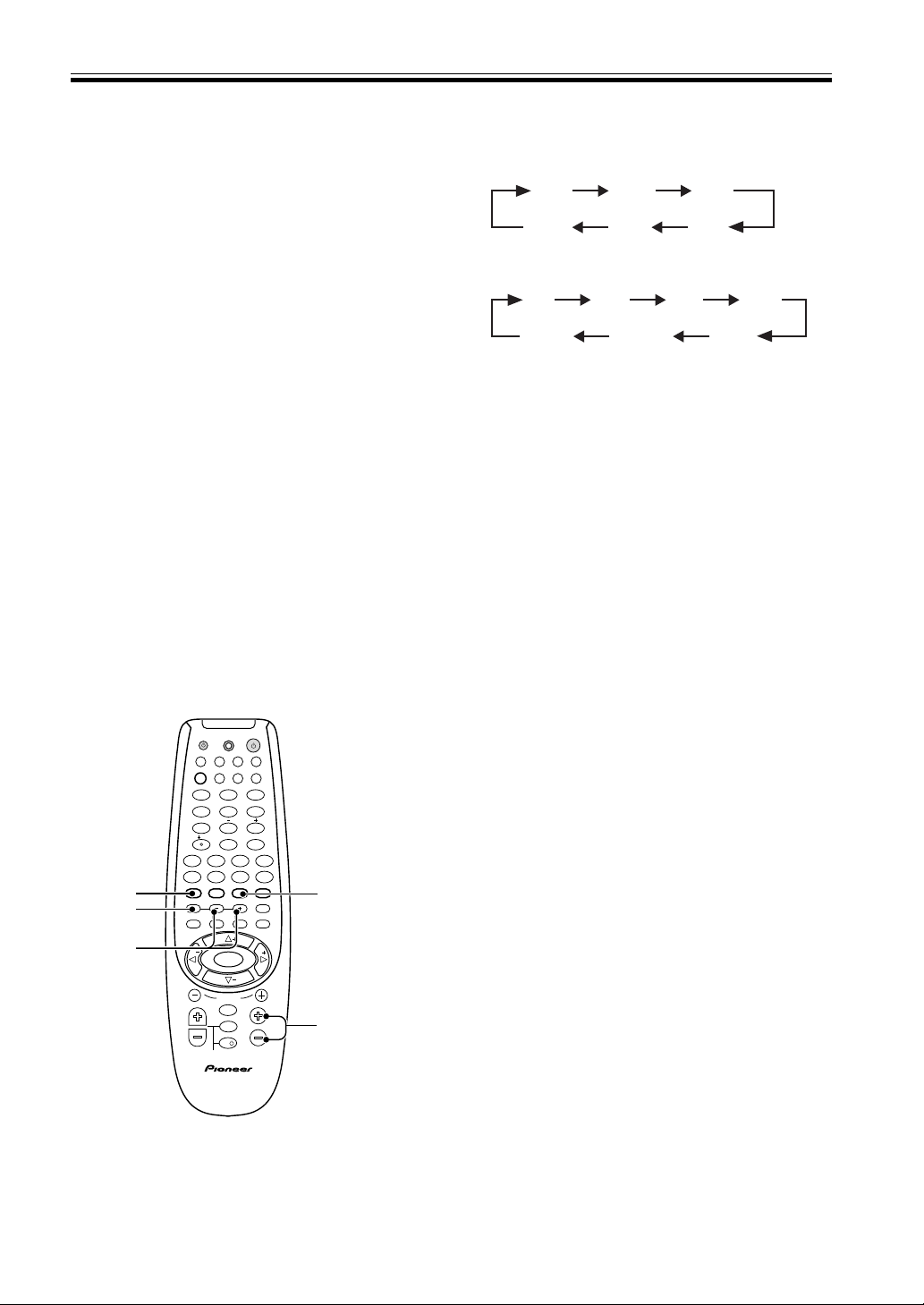
21
En
Preparations
Optical digital input 4 setting (VSX-
D850S only)
Here you tell the receiver what component you have
hooked up to the optical input jack 4.
Press % or fi to select the optical digital
input 2 (DVD, TV, CD, CD-R, VCR, or OFF).
After you assign a component to this digital jack
whenever you select that component, for example a
CD player, the receiver will automatically change to
the digital input setting. You can see this in the
DIGITAL/ANALOG indicator on the front of the
receiver.
MEMO:
• The initial setting is “VCR”.
• The digital out signal corresponds to the selected
input function (for example, DVD).
3 Press TEST TONE to output the test tone.
The test tone is output in the following order.
• Test tone is only output in Dolby/DTS modes. The
test tone sequence corresponds to the speaker setting
mode.
4 Adjust speaker levels so that you hear the
test tone at the same volume from each
speaker when seated in the main listening
position.
• If a speaker is deselected in the speaker setting mode
(see p. 17) then no test tone will be output for that
speaker.
• The channel level range is ± 10 dB.
• Levels can be set for each surround mode.
5 Press TEST TONE to turn off the test tone.
MEMO:
• Since the SUBWOOFER transmits an ultra-low
frequency its sound may seem quieter than it actually
is.
• The speaker volume can be adjusted without
outputting the test tone by pressing CH LEVEL or
CH SELECT button.
• Initial setting is 0 dB.
• You can set each sound mode individually and these
settings are completely independent of each other.
The sound modes you can set include DSP, stereo,
DVD 7.1 Ch and 2/DTS, as explained in steps
above. However, you can only use the test tone
feature when setting 2/DTS.
TV
TVFUNC
MENU
VOLUME
MASTER VOLUME
TV CONTROL
AV PRE-PROGRAMMED AND LEARNING
REMOTE CONTROL UNIT
CHANNEL
ENTER
ENTER
DISC
DTV INFO
MPX/RETURN
DTV ON/OFF DTV MENU
D.ACCESS GUIDE
ST
TUNE
TUNE
ST
CLASS
ATT
BAND
/DTS DSP
TEST TONE
CH SELECT CH LEVEL FUNCTION
SIGNAL SELECT
1¡
4
¢
7
8
3
EFFECT
DVD VCR CD-RTV
RCV
TUN
TVC
CD
MIDNIGHT
LOUDNESS
MUTING
SETUP
FL DIMMER
MULTI CONTROL
5.1 / 7.1
RECEIVER
SOURCE
1
2
3
4
5
6
7
8
9
0
10
2
CT FR SRFL
VSX-D810S/D850S
SW SBSL
CT FR
SR
FL
VSX-D710S
SW SL
Setting the Volume Level of
Each Channel (adjusting the
speaker volume balance)
Use to set the relative volume of each channel.
1 Press 2/DTS.
2 Press MASTER VOLUME + or – to adjust the
volume to an appropriate level.
1
3,5
4
2
CH SELECT
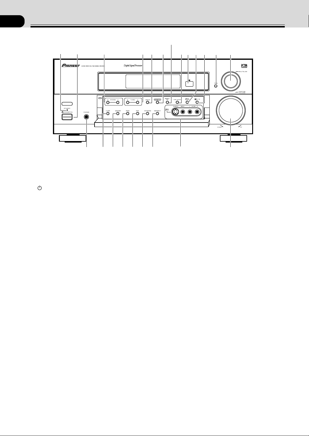
22
En
05
Displays & Controls
Front Panel
1
N∫m-Û˘,?∫
#$%^&*
(!
@
1
2
34
5
7
8
6
9
~
=
0-
1 STANDBY indicator
Lights when the receiver is in standby mode (note
that the receiver consumes a small amount of power
(1W) in standby mode).
2
STANDBY/ON button
Switches the receiver between on and standby (note
that the receiver consumes a small amount of power
(1W) in standby mode).
3 STATION (+/–) buttons (see pages 32-33)
Selects station memories when using the tuner.
4 TUNING (+/–) buttons (see pages 32-33)
Selects the frequency when using the tuner.
5 DIRECT button
Use to switch DIRECT playback on or off. This mode
bypasses the tone controls, channel levels, 2/DTS
and DSP modes for the most accurate reproduction of
a program source.
6 MONITOR button
Press to switch tape monitoring on/off.
7 DIGITAL NR button (VSX-D810S/D850S)
Switches the DIGITAL NR on or off .
DVD5.1CH button (VSX-D710S) (see page 31)
On the VSX-D810S/D850S use this button to
switches the DIGITAL NR on or off. On the VSX-
D710S this button switches between DVD5.1CH
input and regular DVD input.
8 DSP MODE button (see page 28, 30)
Use to switch between the various DSP modes
available (
HALL1, HALL 2, JAZZ, DANCE,
THEATER1, THEATER 2, 6CH STEREO [VSX-
D810S/D850S only]) and DSP off. Use this
button to create different surround sound effects from
any stereo source.
9 Remote sensor
Receives the signals from the remote control.
0 SIGNAL SELECT button (see page 29)
Use to select an analog or digital or AUTO (VSX-
D810S/D850S only) signal.
- 2 /DTS button (see pages 27, 29)
Use to switch between the various Dolby/DTS
surround modes.
(VSX-D710S DVD5.1CH button)
= TONE button
This button allows you to activate the BASS &
TREBLE controls. To adjust the BASS and/or TREBLE
use the MULTI JOG DIAL. Tone can only be used in 2
channel stereo sound mode. The tones controls have
no effect on the B speaker system.
~ MULTI JOG dial
You can use this dial for two purposes. Firstly, in
normal mode turn it to select a source component.
Secondly, use it to adjust the BASS and/or TREBLE
levels when the TONE button has been activated (as
explained above).
! MASTER VOLUME
Use to set the overall listening volume.
@ VIDEO INPUT jacks
Connect a video camera, video game system, etc. to
the
VIDEO INPUT jacks (refer to page 10).
# MIDNIGHT button (see page 31)
Use when listening to movie soundtracks at low volume.
This feature will enable you to hear quiet sounds and
not get jolted by loud or sudden sound effects.
$ SPEAKERS button
Use to switch the speaker system
A = B = A+B =
off. In B and A+B speaker modes you hear only 2 channel
stereo sound.
% MPX button (see page 32)
lf the
TUNED or STEREO indicators don't light when
tuning to an FM station because the signal is weak,
press the MPX button to switch the receiver into
mono reception mode. This should improve the
sound quality and allow you to enjoy the broadcast.
^ BAND button (see page 32-33)
Press to select the AM or FM band.
& MEMORY button (see page 33)
Press to memorize a station for recall using the
STATION (+/–) buttons.
* CLASS button (see pages 33)
Switches between the three banks (classes) of station
memories.
( PHONES jack
Use to connect headphones but this does not switch
the speakers off.
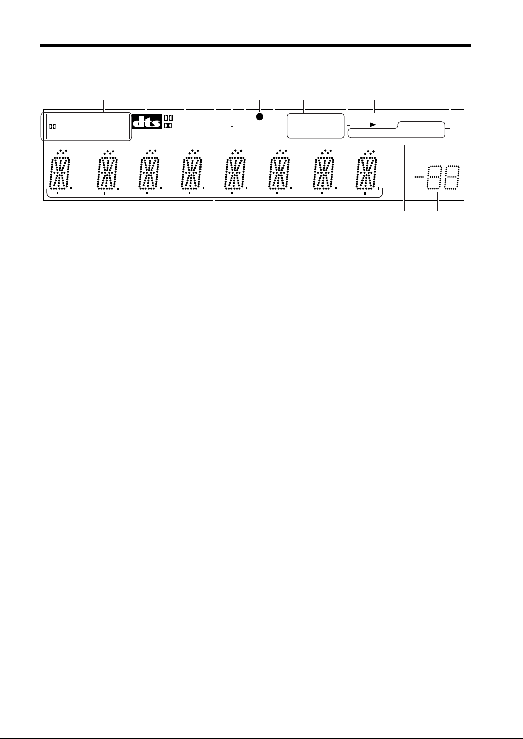
23
En
Displays & Controls
Display
1 SIGNAL SELECT indicators
Light to indicate the type of input signal assigned for
the current component (see “Front Panel“, 0
SIGNAL SELECT). When the AUTO setting is being
used on VSX-D810S & VSX-D850S receivers a set of
brackets will appear around the SIGNAL SELECT
indicators.
2DIGITAL : Lights when a DOLBY DIGITAL
signal is played.
DTS: Lights when a source with DTS audio signals is
played.
ANALOG : Lights when an analog signal is selected.
DIGITAL
: Lights when a digital audio signal is selected.
[ ]: Lights when the AUTO setting is selected. (VSX-
D810S/D850S only)
2 DTS indicator
Lights when DTS mode is being used.
3 2 DIGITAL indicator
When the 2 (DOLBY)/DTS mode of the receiver is
on, this lights to indicate playback of a Dolby Digital
signal. However, 2 PRO LOGIC lights during 2
channel playback of Dolby Digital.
4 2 PRO LOGIC indicator
When the 2 (DOLBY)/DTS mode of the receiver is
on, this lights to indicate playback of a Dolby Pro
Logic source.
5 DSP indicator
Lights when any Advanced Theater or DSP mode is
selected.
6 Surround Back indicator
(VSX-D810S/D850S only)
Lights when most Surround Back channel flag encoded
(6.1channel) software is playing. (With some Surround
Back channel software the surround back indicator
won’t light because there is no flag encoded in the
software.) If you play DTS 5.1/6.1 channel software
surround sound will be heard whether it is encoded
with a surround back channel flag or not.
7 OVERLOAD indicator
This lights when an analog signal is too strong (the
SIGNAL SELECT needs to be on ANALOG). It
indicates the sound is distorting and the input signal
should be reduced.
8 ATT indicator
Lights when ATT is used to attenuate (reduce) the
level of the input signal (can only be used in
ANALOG mode).
1
2
3
4
87
9
0 =
5
6
-
~
@
!
SIGNAL SELECT
MIDNIGHT
LOUDNESS
DIRECT
MONITOR
TUNED
MONO
ANALOG DIGITAL
SP AB
DIGITAL DTS
DIGITAL
PRO LOGIC
SB ATT
DSP
DNR
STEREO
dB
9 DIRECT indicator
Lights when source DIRECT is in use. This function
bypasses all tone, channel levels, DSP and Dolby
Surround effects.
MIDNIGHT indicator
Lights when MIDNIGHT listening mode is in use.
LOUDNESS indicator
Lights when the LOUDNESS is on. LOUDNESS is
used to boost the bass and treble when listening at
low levels.
0 SPEAKER indicator
Shows if the speaker system is on or not. SP 3A
(and/or) B means speakers are switched on. SP 3
means speakers are switched off.
- MONITOR indicator
Lights when MONITOR is selected to hear a
recording as it's being made (see page 34).
= TUNER indicators
MONO:
Lights when the mono mode is set using the
MPX MODE button.
TUNED:
Lights when a broadcast is being received.
STEREO:
Lights when a stereo FM broadcast is being received
in auto stereo mode.
~ MASTER VOLUME LEVEL
Shows the overall volume level. Volume level is
maintained even when the power is off. ---dB
indicates the minimum level, and 0dB indicates the
maximum level.
• Depending on the level settings you make for
individual channels, the MAX level can range
between –10dB and 0dB.
! DNR indicator (VSX-D810S/D850S only)
Lights when the digital noise reduction is on. Use to
reduce extraneous noise. It can be used with any
sound mode.
@ CHARACTER display
Shows the radio frequency or function (DVD/LD,
CD, etc.) receiver is using.
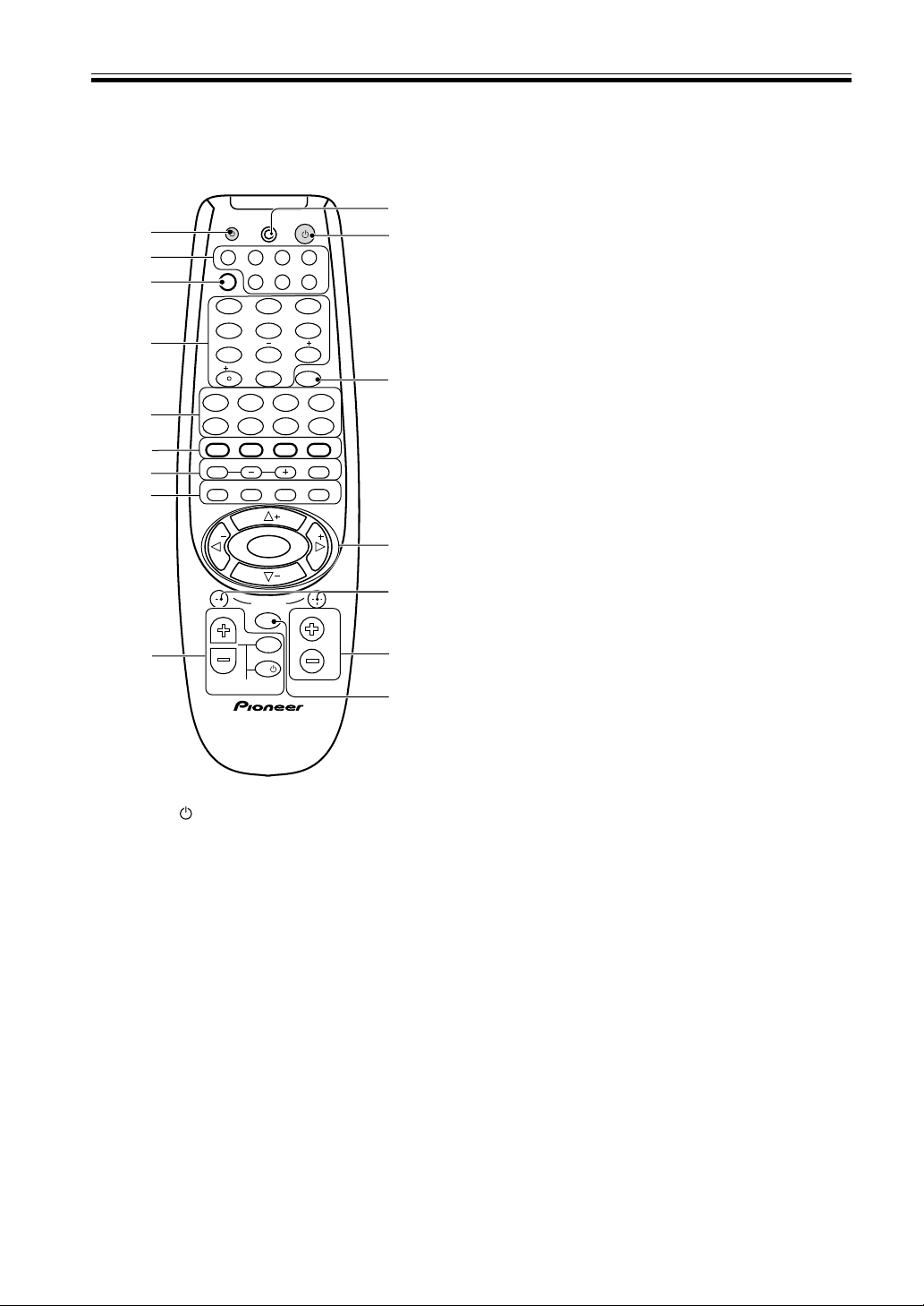
24
En
Displays & Controls
Remote Control
(VSX-D710S/D810S)
TV
TVFUNC
MENU
VOLUME
MASTER VOLUME
TV CONTROL
AV PRE-PROGRAMMED AND LEARNING
REMOTE CONTROL UNIT
CHANNEL
ENTER
ENTER
DISC
DTV INFO
MPX/RETURN
DTV ON/OFF DTV MENU
D.ACCESS GUIDE
ST
TUNE
TUNE
ST
CLASS
ATT
BAND
/DTS DSP
TEST TONE
CH SELECT CH LEVEL FUNCTION
SIGNAL SELECT
1¡
4
¢
7
8
3
EFFECT
DVD VCR CD-RTV
RCV
TUN
TVC
CD
MIDNIGHT
LOUDNESS
MUTING
SETUP
FL DIMMER
MULTI CONTROL
5.1 / 7.1
RECEIVER
SOURCE
1
2
3
4
56
7
8
9
0
10
2
3
@
!
0
2
1
4
5
9
-
~
=
#
7
6
8
1 SOURCE button
Use to turn on/off other components connected to
the receiver.
2 MULTI CONTROL buttons
Use to put the receiver/remote control in the stated
mode.
For other equipment controls, see Controlling the
Rest of Your System on pages 35-49.
3 RCV button (see page 16)
Use this button when setting up the surround sound
for the receiver. Also press it if you want to use
special features attached to some of the number
buttons, for example MIDNIGHT, 5.1/7.1, or ATT.
4 NUMBER/MODE buttons
Use the number buttons to select the radio frequency
in tuner DIRECT ACCESS (see page 32) mode or the
tracks in CD, DVD mode etc.
Also, buttons marked with the following names have
special functions. If you try to use one of these
functions but the display flashes it means that
function cannot be used in the current mode (for
example DSP modes cannot be used when 5.1 Ch
setting is on).
MIDNIGHT (see page 31)
Use to put receiver in MIDNIGHT mode. To use first
press the RCV button then operate this button.
5.1 Ch (VSX-D710S) 7.1Ch (VSX-D810S/D850S)
(see page 31)
When the DVD/LD or DVD 5.1/7.1 Ch function is
selected each press switches the DVD/LD input
between DVD/LD and DVD 5.1/7.1 Ch. To use first
press the RCV button then operate this button.
ATT
When the overload indicator lights use this button to
attenuate (lower) the level of an analog input signal
and prevent distortion. To use first press the RCV
button then operate this button.
EFFECT +/– buttons (see page 30)
Use to add or subtract the amount of effect in
different DSP sound modes (except 6 Ch Stereo) or
advanced listening modes.
To use first press the RCV button then operate these
buttons.
5 THE FOLLOWING BUTTONS ARE BOTH
CONTROLS FOR OTHER COMPONENTS (LIKE
A DVD PLAYER) AND DEDICATED TUNER
CONTROLS. THE TUNER CONTROLS ARE
EXPLAINED HERE. YOU CAN USE THEM
AFTER YOU HAVE PUSHED THE TUNER MULTI
CONTROL BUTTON.
BAND button (see pages 32, 33)
Use to switch between the AM and FM band when in
TUNER mode.
CLASS button (see pages 33)
Use to switch between the three banks (classes) of
station memories.
MPX/RETURN button (see page 32)
Use to switch between auto stereo and mono
reception of FM broadcasts. If the signal is weak then
switching to MONO will improve the sound quality.
Also, this is the pause button for CDs, tapes, DVDs,
etc.
D. ACCESS button (see page 32)
Use to directly access a radio station by pressing the
number of the station you want.
DTV INFO button
Use to bring up information screens on a digital TV.
DTV MENU button
Use to bring up menus on a digital TV.
DTV ON/OFF button
Use to turn a digital TV on/off.
GUIDE button
Use to bring up the guides on a digital TV.

25
En
Displays & Controls
0 MENU button
Use to access different menus associated with your
DVD player.
- MASTER VOLUME +/– buttons
Use to set the overall listening volume.
= CHANNEL +/– buttons
Use to select the stations of memorized radio
frequencies. Also use to skip tracks backward or
forward on CDs, DVDs, etc.
~ @ # % fi ( TUNE/ST +/–) & ENTER buttons (see
pages 16-21)
Use these arrow buttons when setting up your
surround sound system (see pages 16-21). These
buttons are also used to control DVD menus/options
and for deck 1 of a double cassette deck player. The
TUNE/ST +/– buttons can be used to find radio
frequencies and preset stations, respectively.
! DISC (ENTER) button
Use to select a disc an in multi-CD player. To use
first press the RCV button then operate this button.
@ RECEIVER
(POWER) button
This switches between STANDBY mode and power
ON for this receiver.
# LED DISPLAY (see pages 35-40)
This display flashes when a command is sent from
the remote control to the receiver. It also flashes at
other times, for example when teaching the receiver
preset codes, with specific meanings.
6 2 /DTS button (see pages 27, 29)
Use to put receiver in DOLBY DIGITAL, DOLBY
SURROUND and DTS modes.
DSP button (see pages 28, 30)
Use to put receiver in one of the DSP modes.
TEST TONE button (see page 21)
Use to sound the TEST TONE when setting up the
surround sound of the receiver (the 2 /DTS mode
must be on).
SIGNAL SELECT (see page 29)
Use to select the proper signal (analog, digital) for the
source your are inputting. On the VSX-D810S &
VSX-D850S receivers there is an AUTO setting. In
this setting the receiver will automatically switch
between the analog and digital signals according to
what is being input. If both signals are input the
AUTO setting will choose the digital one. This setting
is convenient as the receiver will always choose the
best or appropriate signal.
7 CH SELECT button (see page 21)
Use to select a speaker when setting up the surround
sound of the receiver. To use first press the
RCV
button then operate this button.
CH LEVEL +/– (see page 21)
Use to set up the levels of the surround sound of the
receiver. To use first press the RCV button then
operate this button.
FUNCTION button
Use to select the playback or recording source. This
button lets you cycle through the different functions
of the receiver in the following order: CD, TUNER,
AUX, CDR/TAPE, VCR/DVR, DVD/LD, DVD 7.1 Ch,
VIDEO, and TV/SAT (VSX-D810S/D850S).
CD, TUNER, AUX, CDR/TAPE, VCR/DVR, DVD/LD,
VIDEO, and TV/SAT (VSX-D710S).
8 LOUDNESS button
Use to switch on the loudness. This feature is useful
for getting good bass and treble sounds listening at
low volumes.
FL DIMMER button
Use this button to make the fluorescent display (FL)
dimmer or brighter. There are three brightness
settings as well as an off setting.
SETUP button (see page 35-40)
Use this button when setting up the remote control to
control other components.
MUTING button
Use to mute the sound or restore the sound if it has
been muted.
9 THE FOLLOWING BUTTONS ARE DEDICATED
TV CONTROL. THEY ARE ONLY USED FOR
CONTROLLING YOUR TV.
TV FUNC button
Use select the TV function.
TV
button
Use to turn on/off the power of the TV.
TV VOLUME +/– buttons
Use to adjust the volume on your TV.
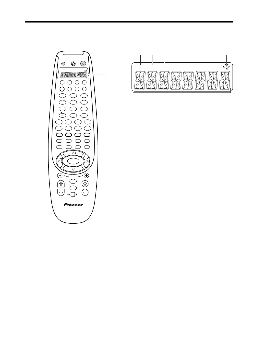
26
En
Displays & Controls
Remote Control
(VSX-D850S)
1 LCD display
2 SETUP
Indicates that the remote is in Setup mode.
3 SEARCH
Indicates that the remote is in preset code Search
mode.
4 SEARCH BY BRAND
Indicates that the remote is in preset code Search by
brand mode.
5 LEARN
Indicates that the remote is in Learning mode and
ready to learn signals from other remote controllers.
6 ERASE
Indicates that the remote is in Erase mode.
7 Transmit icon
Blinks to indicate the remote is transmitting control
signals.
8 CHARACTER display
Shows preset codes and other information.
TV
TVFUNC
MENU
VOLUME
MASTER VOLUME
TV CONTROL
AV PRE-PROGRAMMED AND LEARNING
REMOTE CONTROL UNIT
CHANNEL
ENTER
ENTER
DISC
DTV INFO
MPX/RETURN
DTV ON/OFF DTV MENU
D.ACCESS GUIDE
ST
TUNE
TUNE
ST
CLASS
ATT
BAND
/DTS DSP
TEST TONE
CH SELECT CH LEVEL FUNCTION
SIGNAL SELECT
1¡
4
¢
7
8
3
EFFECT
DVD VCR CD-RTV
RCV
TUN
TVC
CD
MIDNIGHT
LOUDNESS
MUTING
SETUP
FL DIMMER
MULTI CONTROL
5.1 / 7.1
RECEIVER
SOURCE
1
2
3
4
5
6
7
8
9
0
10
2
SETUP
SEARCH SEARCH
BY BRAND
LEARN ERASE
1
LCD Display
(VSX-D850S only)
SETUP
SEARCH
LEARN ERASE
SEARCH
BY BAND
2
8
3
4
75 6
27
En
Sound Modes
Learning about the Sound Modes
The sound modes are explained here.
There are two cinema modes: 2 STANDARD, and ADVANCED THEATER. These are designed to be used with multi
channel surround sound audio/visual sources (like DVDs and LDs). Intrinsic to home theater, these modes can deliver
realistic and powerful surround sound that recreates the movie theater experience. You may need to experiment with
them to see which settings suit your home system and personal tastes.
The DSP and STEREO modes are designed to be used with music sources but some DSP modes are also suited for
film soundtracks. Again, try different settings with various soundtracks to see which you like.
2 (STANDARD) mode
This mode is for pure decoding of Dolby Digital, DTS and Dolby Surround sources. No special effects are added. It is
good for enjoying movies that have been recorded in Dolby Digital, DTS or Dolby Surround.
You can identify Dolby Digital software by the 1 or
marks. Most Dolby Surround software is
marked 3, but unmarked software may also incorporate Dolby Surround.
ADVANCED THEATER modes
MUSICAL
Simulates the acoustic environment of a large concert hall and is suitable for music or musical sources marked 1
( ) or
R
.
DRAMA
Simulates the relaxed environment of a classic medium size movie theater, and is suitable for watching dramas on
sources marked 1 ( ) or
R
.
ACTION
Simulates the acoustic environment of a large modern movie theater. You can enjoy the power and dynamics of
motion picture audio which is best used with action movies on sources marked 1 ,
or
R
.
EXPANDED (VSX-D710S)
This mode is especially designed to give sound depth to stereo sources. The overall effect builds a dynamic and broad
sound space, allowing two-channel (stereo) signals to faithfully imitate a five speaker sound. Use with Dolby Pro
Logic for a stereo surround effect. You can also use with Dolby Digital sources for a wider stereo field than
STANDARD mode.
5/6-D THEATER (VSX-D810S/D850S)
This mode is especially designed to give sound depth to stereo sources. The overall effect builds a dynamic and
broad sound space, allowing two-channel (stereo) signals to faithfully imitate a six speaker sound. The mode should
be used in conjunction with Dolby Pro Logic for sources bearing the
DOLBY SURROUND
mark.
06

28
En
DSP modes
The DSP (Digital Signal Processing) modes allow you to transform your living room into a variety of different sonic
environments when playing standard (two-channel) stereo sources, Dolby Pro Logic sources, and Dolby Digital
sources. DSP modes do not work when the speakers are off.
HALL 1
Simulates the acoustic environment of a large, wooden concert hall. Complex delay of reflected sounds coupled with
reverberation effects create the dynamic and beautiful sound characteristics of an orchestra performing in a concert
hall, making it suitable for classical music
HALL 2
Simulates the acoustic environment of a concert hall with stone walls. The rich reverberations and natural fullness of
the sound create the auditory impression of being in a concert hall, also making it suitable for classical music.
JAZZ
Simulates the acoustic environment of a jazz club. Less delay on the reflected sounds emphasizes the sensation of
hearing a live band.
DANCE
Simulates the acoustic environment and strong bass sound of a dance club. A short delay on the reflected sounds
emulates the raw power of the dance music.
THEATER 1
Adjusts the delay of the reflected sound to simulate the acoustic environment of a medium sized movie theater.
THEATER 2
Simulates the acoustic environment of a theater while maintaining proper localization of each channel.
5/6Ch STEREO (VSX-D810S/D850S)
This mode reproduces stereo sound but uses all the speakers in the system to induce a rich, all-around sound.
MEMO:
• When using 96 kHz PCM playback, STANDARD, ADVANCED THEATER, and DSP sound modes are not
available.
Sound Modes
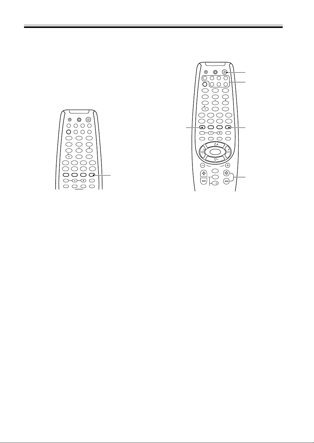
29
En
Switching ANALOG/DIGITAL
Signal Input
When you select a function (for example CD) that is
only hooked up by a digital connection, then the
ANALOG/DIGITAL signal input switch will
automatically choose digital for VSX-D810S/D850S. If
you have that function hooked up by both digital and
analog connections this switch lets you choose which to
listen to.
Sound Modes
Playing Sources with Dolby
Digital or DTS Sound
1 Turn on the power of the playback
component.
2 Turn on the power of the receiver.
Be sure that the standby indicator turns off on the
front panel.
3 Press MULTI CONTROL buttons or the
FUNCTION button to select the source you
want to playback.
If the DIRECT FUNCTION is OFF you have to use
the FUNCTION button to select the source (see
p.39).
4 Press SIGNAL SELECT to select DIGITAL.
(Refer to “Switching ANALOG/DIGITAL signal input”
on this page.)
5 Press 2/DTS to switch the Dolby/DTS mode
on.
6 Start playback of the component you
selected in step 1.
7 Press MASTER VOLUME (+/–) to adjust the
volume level.
MEMO:
• You can only hear the sound on DTS encoded discs if
the CD or LD player with DTS is digitally connected
to this receiver. If you play a DTS encoded disc
through analog connections you will only hear digital
noise, not the soundtrack. To prevent noise, you need
to make digital connections (Refer to page 6-7) and
set SIGNAL SELECT to “DIGITAL”.
ENTER
DISC
DTV INFO
MPX/RETURN
DTV ON/OFF DTV MENU
D.ACCESS GUIDE
CLASS
ATT
BAND
/DTS DSP
TEST TONE
CH SELECT CH LEVEL FUNCTION
SIGNAL SELECT
1¡
4
¢
7
8
3
EFFECT
DVD VCR CD-RTV
RCV
TUN
TVC
CD
MIDNIGHT
LOUDNESS
MUTING
SETUP
FL DIMMER
MULTI CONTROL
5.1 / 7.1
RECEIVER
SOURCE
1
2
3
4
5
6
7
8
9
0
10
2
4
7
2
5
3
TV
TVFUNC
MENU
VOLUME
MASTER VOLUME
TV CONTROL
CHANNEL
ENTER
ENTER
DISC
DTV INFO
MPX/RETURN
DTV ON/OFF DTV MENU
D.ACCESS GUIDE
ST
TUNE
TUNE
ST
CLASS
ATT
BAND
/DTS DSP
TEST TONE
CH SELECT CH LEVEL FUNCTION
SIGNAL SELECT
1¡
4
¢
7
8
3
EFFECT
DVD VCR CD-RTV
RCV
TUN
TVC
CD
MIDNIGHT
LOUDNESS
MUTING
SETUP
FL DIMMER
MULTI CONTROL
5.1 / 7.1
RECEIVER
SOURCE
1
2
3
4
5
6
7
8
9
0
10
2
1 Press SIGNAL SELECT to select the input
signal corresponding to the source
component.
Each press switches between ANALOG and DIGITAL
signal selection (VSX-D710S).
On the VSX-D810S & VSX-D850S receivers there is
an AUTO setting. In this setting the receiver will
automatically switch between the analog and digital
signals according to what is being input. If both
signals are input the AUTO setting will choose the
digital one. This setting is convenient as the receiver
will always choose the best or appropriate signal.
2 While SIGNAL SELECT is set to DIGITAL,
2 DIGITAL lights when a Dolby Digital
signal is input, DTS lights when a DTS signal
is input.
MEMO:
• SIGNAL SELECT is fixed in the “ANALOG” position
for components not assigned to one of the digital
input jacks.
• This receiver can only play back Dolby Digital, PCM
(32kHz, 44kHz, and 48kHz [VSX-D810S & VSX-
D850S can play 96kHz]), and DTS, digital signal
formats. With digital signal formats other than these,
set SIGNAL SELECT to “ANALOG”.
• Some DVD players don’t output DTS signals. For
more details, refer to the instruction manual supplied
with your DVD player.
1
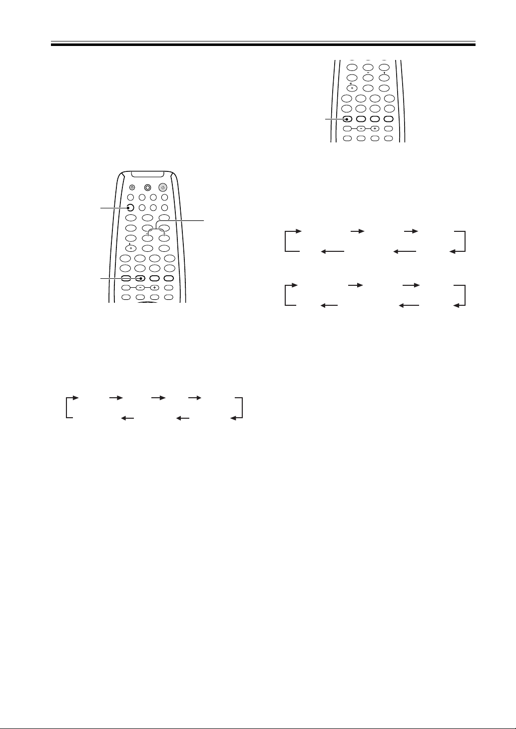
30
En
ADVANCED THEATER mode ( Dolby/
DTS mode)
Switch on the Dolby/DTS mode by pressing the 2/DTS
button. When Dolby/DTS mode is ON, Dolby Pro Logic,
Dolby Digital and DTS, and signal processing is per-
formed automatically corresponding to the input signal.
Use this button to cycle through the various modes.
When the STANDARD mode is selected, DSP modes are
off.
1 Switch the Dolby/DTS mode on and off by
pressing 2/DTS on the remote control or
2/DTS on the front panel.
Each press changes the display as follows.
*When using DTS 5.1/6.1 ch discs in STANDARD
mode the display will change to “DTS-ES”. Naturally
the playback will still be 6.1 output.(VSX-D810S/
D850S)
Refer to page 27 for more details about each
surround effect.
MEMO:
• The effects of Dolby/DTS mode can be adjusted in
the range of 10 to 90 by pressing EFFECT +/– (the
default setting is 70). Also, the effect level can be set
in each ADVANCED THEATER mode by pressing the
EFFECT +/– button. The STANDARD mode cannot
be changed.
• For the VSX-D810S/VSX-D850S, when the surround
back channel is set to off in the speakers settings, 6-D
Theater becomes 5-D Theater.
1
ENTER
DISC
DTV INFO
MPX/RETURN
DTV ON/OFF DTV MENU
D.ACCESS GUIDE
CLASS
ATT
BAND
/DTS DSP
TEST TONE
CH SELECT CH LEVEL FUNCTION
SIGNAL SELECT
1¡
4
¢
7
8
3
EFFECT
MIDNIGHT
LOUDNESS
MUTING
SETUP
FL DIMMER
5.1 / 7.1
4
5
6
7
8
9
0
10
2
DRAMA
* STANDARD
(VSX-D810S/D850S)
MUSICAL
ACTION5/6-D THEATEROFF
DRAMA
STANDARD
MUSICAL
ACTIONEXPANDED
(VSX-D710S)
OFF
Sound Modes
Selecting a Sound Mode
To ensure the best possible surround sound, be sure to
complete the set up procedures described in “Setting Up
for Surround Sound” (starting on page 16) before using
the sound modes. This is particularly important when
using the 2 (Dolby) surround mode.
Surround operation
1 Press RCV.
This sets the remote to select the sound mode.
(You can skip this step when using the controls on
the receiver.)
2 Press DSP MODE to select the sound mode.
Each press changes the DSP mode as follows:
MEMO:
• The amount of effect of each DSP mode can be
adjusted in the range of 10 to 90 (the default setting
value is 70) by pressing EFFECT +/–.
• The DSP effects can’t be heard in 6 channel stereo
(VSX-D810S/D850S only).
• For VSX-D810S/VSX-D850S receivers, when the
surround back channel is set to off 6 channel stereo
becomes 5 channel stereo.
ENTER
DISC
DTV INFO
MPX/RETURN
DTV ON/OFF DTV MENU
D.ACCESS GUIDE
CLASS
ATT
BAND
/DTS DSP
TEST TONE
CH SELECT CH LEVEL FUNCTION
SIGNAL SELECT
1¡
4
¢
7
8
3
EFFECT
DVD VCR CD-RTV
RCV
TUN
TVC
CD
MIDNIGHT
LOUDNESS
MUTING
SETUP
FL DIMMER
MULTI CONTROL
5.1 / 7.1
RECEIVER
SOURCE
1
2
3
4
5
6
7
8
9
0
10
2
EFFECT +/–
1
2
JAZZ
DANCE
HALL 1
HALL 2
THEATER 1THEATER 26CH STEREO
(VSX-D810S
/D850S only)
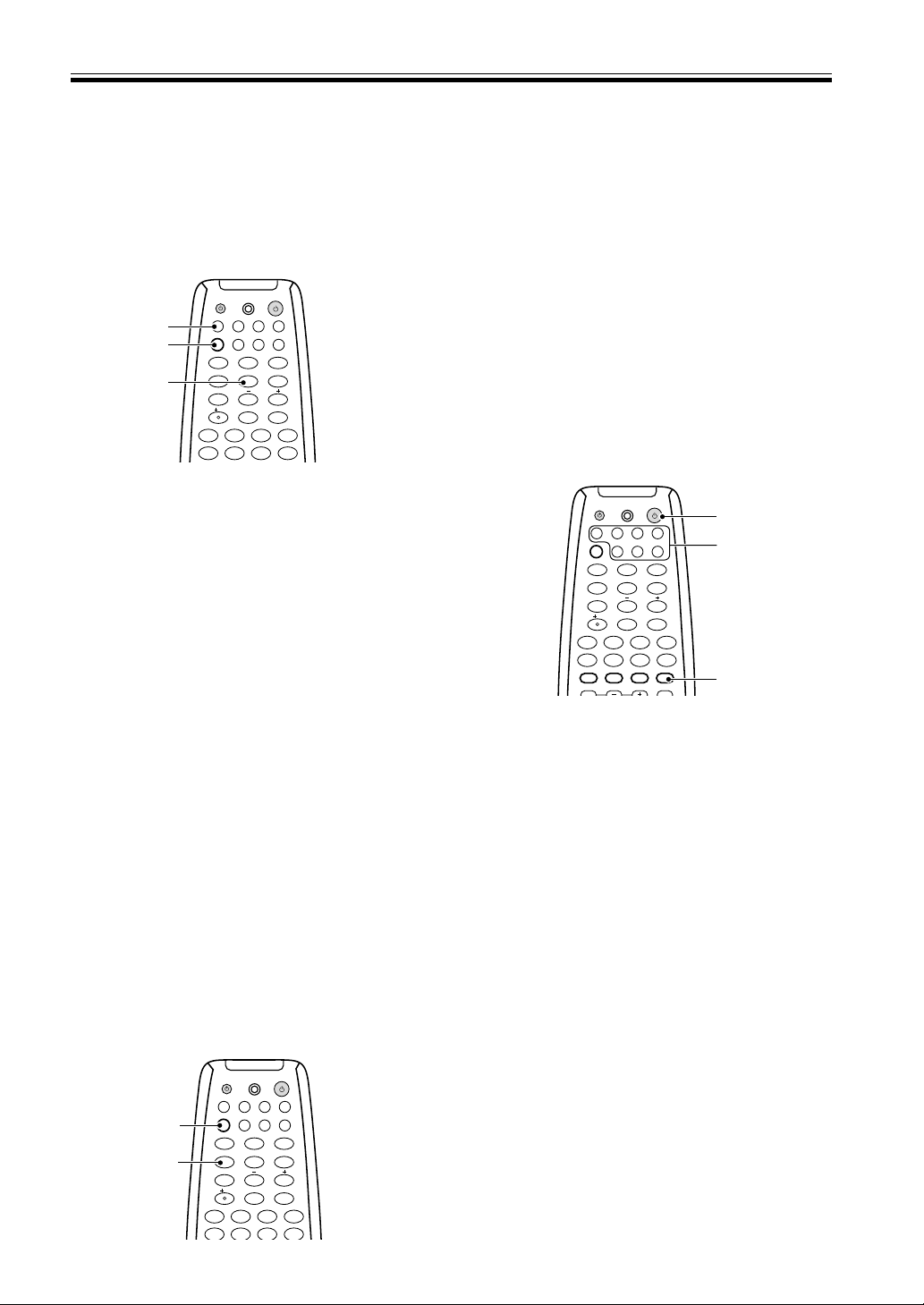
31
En
Sound Modes
1
2
ENTER
DISC
DTV INFO
MPX/RETURN
DTV ON/OFF DTV MENU
D.ACCESS GUIDE
CLASS
ATT
BAND
1¡
4
¢
7
8
3
EFFECT
DVD VCR CD-RTV
RCV
TUN
TVC
CD
MIDNIGHT
MULTI CONTROL
5.1 / 7.1
RECEIVER
SOURCE
1
2
3
4
5
6
7
8
9
0
10
1 Press RCV.
This sets the remote to select the sound mode.
(You can skip this step when using the controls on
the receiver.)
2 Press MIDNIGHT.
Each press switches MIDNIGHT listening mode on or
off.
MEMO:
• The effect automatically adjusts according to the
volume level.
MIDNIGHT Listening Mode
When listening at low volume, surround effects tend to
become less than satisfactory. Turn the MIDNIGHT
listening mode on to enjoy the effects of quality
surround sound even at low volumes. This mode allows
you to hear effective surround sound of movies at low
volume levels.
To switch on DVD 7.1 ch (5.1 ch for VSX-
D710S) mode press the DVD/LD MULTI
CONTROL
button on the remote, then RCV,
then 5.1/7.1 button.
VSX-D710S only: On the main unit press the
DVD 5.1CH button to switch on 5.1 ch mode.
Press the 5.1/7.1 button on the remote to go
back to the DVD/LD mode. If you’re using
the main unit, choose any other function
with the MULTI JOG.
MEMO:
• When 5.1 ch/7.1 ch input is selected, Dolby mode,
DSP mode, SIGNAL SELECT, ATT, DIRECT, TONE,
MIDNIGHT mode, LOUDNESS and speakers B
cannot be operated.
• When 5.1 ch/7.1 ch input is selected, only the
volume level and channel levels can be set.
ENTER
DISC
DTV INFO
MPX/RETURN
DTV ON/OFF DTV MENU
D.ACCESS GUIDE
CLASS
ATT
BAND
1¡
4
¢
7
8
3
EFFECT
DVD VCR CD-RTV
RCV
TUN
TVC
CD
MIDNIGHT
MULTI CONTROL
5.1 / 7.1
RECEIVER
SOURCE
1
2
3
4
56
7
8
9
0
10
2
DVD/LD
MULTICONTROL
RCV
5.1/7.1
DVD 5.1 ch./7.1 ch (5.1 ch for VSX-
D710S) input playback
If you want you can connect a component with 7.1
channel (5.1 channel for VSX-D710S) analog output to
enjoy surround sound playback. In this case the
surround sound will be externally decoded and then fed
into the receiver.
Playing other Sources
1 Turn on the power of the playback
component.
2 Turn on the power of the receiver.
Be sure that the standby indicator turns off on the
front panel.
3 Press MULTI CONTROL buttons or the
FUNCTION button to select the source you
want to playback.
If the DIRECT FUNCTION is OFF you have to use
the FUNCTION button to select the source (see
p.39).
4 If necessary, press SIGNAL SELECT to select
the input signal corresponding to the source
component (see p.29).
5 Start playback of the component you
selected in step 1.
3
2
4
ENTER
DISC
DTV INFO
MPX/RETURN
DTV ON/OFF DTV MENU
D.ACCESS GUIDE
CLASS
ATT
BAND
/DTS DSP
TEST TONE
CH SELECT CH LEVEL FUNCTION
SIGNAL SELECT
1¡
4
¢
7
8
3
EFFECT
DVD VCR CD-RTV
RCV
TUN
TVC
CD
MIDNIGHT
MULTI CONTROL
5.1 / 7.1
RECEIVER
SOURCE
1
2
3
4
5
6
7
8
9
0
10
2
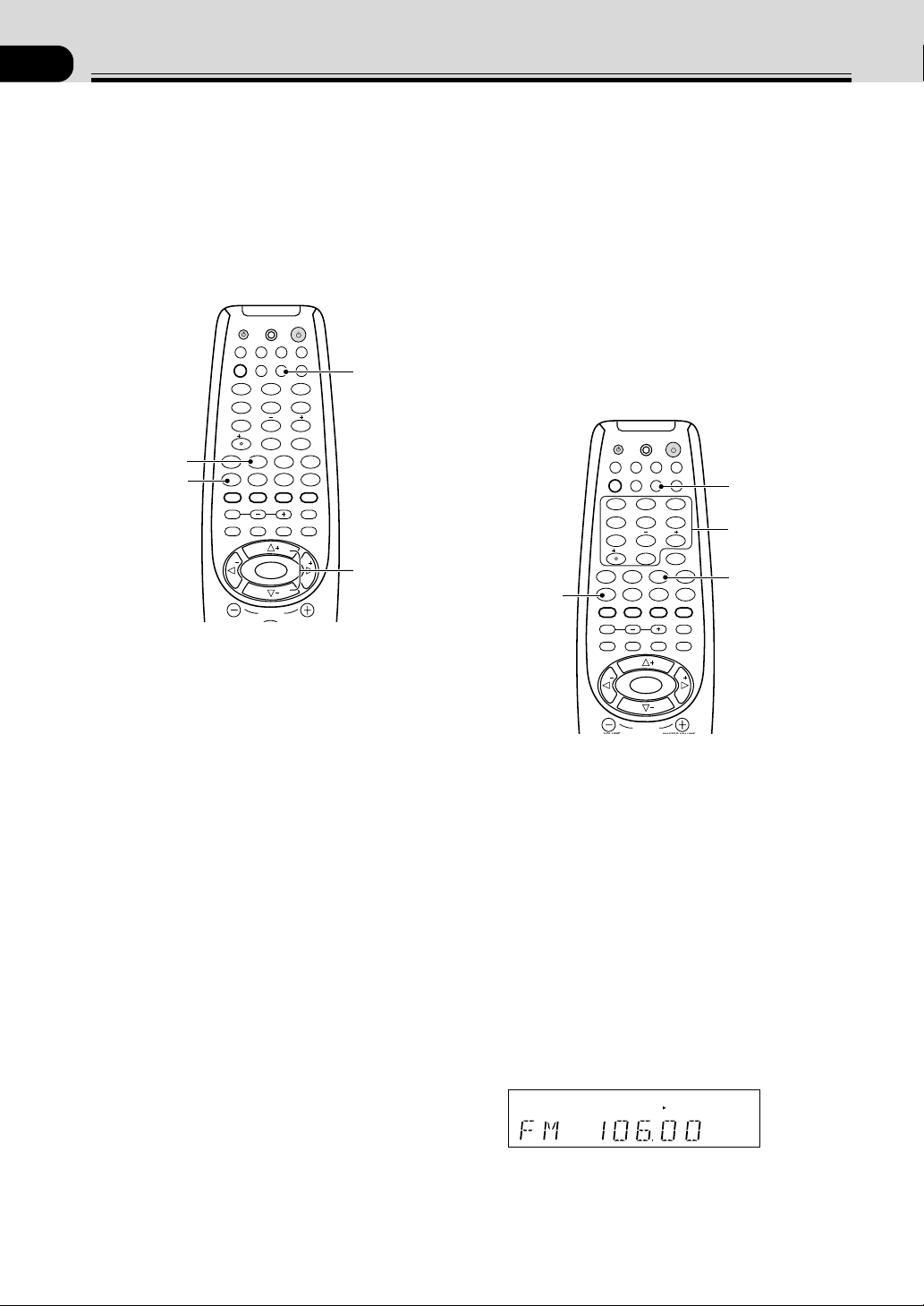
32
En
07
Using the Tuner
Finding a Station
The following steps show you how to tune in to FM and
AM radio broadcasts using the automatic (search) and
manual (step) tuning functions. If you already know the
exact frequency of the station you want to listen to, see
Tuning Directly to a Station on this page. Once you are
tuned to a station you can memorize the frequency for
recall later—see Memorizing Stations on page 33 for
more on how to do this.
1 Press the MULTI CONTROL TUN button on
the remote control.
On the receiver, use the MULTI JOG to select the
tuner mode.
2 Use the BAND button to change the band
(FM or AM), if necessary.
Each press switches the band between FM and AM
On the receiver, pressing the BAND button switches
between bands.
3 Tune to a station.
Automatic tuning
To search for stations in the currently selected band,
press and hold either the TUNE + or TUNE – button
for about a second. The receiver will start searching
for the next station, stopping when it has found one.
Repeat this step to search for other stations.
Manual tuning
To change the frequency one step at a time, press the
TUNE + or TUNE – (%fi) buttons.
High speed tuning
Press and hold the TUNE + or TUNE – button for
high speed tuning, releasing the button once the
desired frequency is reached.
Tuning Directly to a Station
Sometimes, you'll already know the frequency of the
station you want to listen to. In this case, you can simply
enter the frequency directly using the number buttons
on the remote control (this function is not available
using the front panel controls of the receiver).
1 Press the MULTI CONTROL TUN button on
the remote control.
On the receiver, use the MULTI JOG to select the
tuner mode.
2 Press the BAND button to select either FM
or AM.
Each press switches the band between FM and AM.
On the receiver, pressing the BAND button switches
between bands.
3 Press D.ACCESS (DIRECT ACCESS).
4 Use the number buttons to enter the
frequency of the radio station.
Example: To tune to 106.00 (FM), press 1 – 0 – 6 –
0 – 0
SP
A
STEREO
TUNED
MEMO:
• If you make a mistake while inputting the frequency,
press the
D.ACCESS button twice to cancel the
frequency and start again.
2
1
MPX
VOLUME
MASTER VOLUME
CHANNEL
ENTER
ENTER
DISC
DTV INFO
MPX/RETURN
DTV ON/OFF DTV MENU
D.ACCESS GUIDE
ST
TUNE
TUNE
ST
CLASS
ATT
BAND
/DTS DSP
TEST TONE
CH SELECT CH LEVEL FUNCTION
SIGNAL SELECT
1¡
4
¢
7
8
3
EFFECT
DVD VCR CD-RTV
RCV
TUN
TVC
CD
MIDNIGHT
LOUDNESS
MUTING
SETUP
FL DIMMER
MULTI CONTROL
5.1 / 7.1
RECEIVER
SOURCE
1
2
3
4
5
6
7
8
9
0
10
2
3
VOLUME
MASTER VOLUME
CHANNEL
ENTER
ENTER
DISC
DTV INFO
MPX/RETURN
DTV ON/OFF DTV MENU
D.ACCESS GUIDE
ST
TUNE
TUNE
ST
CLASS
ATT
BAND
/DTS DSP
TEST TONE
CH SELECT CH LEVEL FUNCTION
SIGNAL SELECT
1¡
4
¢
7
8
3
EFFECT
DVD VCR CD-RTV
RCV
TUN
TVC
CD
MIDNIGHT
LOUDNESS
MUTING
SETUP
FL DIMMER
MULTI CONTROL
5.1 / 7.1
RECEIVER
SOURCE
1
2
3
4
56
7
8
9
0
10
2
2
1
3
4
MPX mode
If the TUNED or STEREO indicators don't light when
tuning to an FM station because the signal is weak, press
the MPX button to switch the receiver into mono
reception mode. This should improve the sound quality
and allow you to enjoy the broadcast.

33
En
Memorizing Stations
If you often listen to a particular radio station, it's
convenient to have the receiver store the frequency for
easy recall whenever you want to listen to that station.
This saves the effort of manually tuning in each time.
The VSX-D710S/D810S/D850S can memorize up to 30
stations, stored in three banks, or classes, (A,B and C) of
10 stations each. When memorizing FM frequencies, the
receiver also stores the MPX setting (auto stereo or
mono, see p.32). The process for memorizing stations is
only possible from the controls on the front panel of the
receiver.
1 Tune to a station you want to memorize.
See Finding a Station and Tuning Directly to a
Station, on pages 32 and this page, for more on how
to do this.
2 Press MEMORY.
The display shows a blinking memory class.
SP
A
STEREO
TUNED
3 Press CLASS to select one of the three
classes.
Repeatedly pressing this button cycles through the
three available classes, A, B and C.
4 Press STATION +/– to select the desired
station memory number.
Pressing these buttons repeatedly cycles through the
10 available station memories in each class.
After choosing the location you want, the preset class
and number blink for about 5 seconds and the
receiver stores the station.
Repeat steps 1 to 4 to memorize up to 30 stations.
Recalling Memorized Stations
Having memorized up to 30 stations (see the previous
explanation for how to do this), preset stations can be
easily recalled.
1 Press the MULTI CONTROL TUN button on the
remote control.
On the receiver, use the MULTI JOG to select the
tuner mode.
2 Press CLASS to select the class in which the
station is stored.
Repeatedly pressing this button cycles through the
three available classes, A, B and C.
3 Use the ST +/– buttons to select the station
memory in which the station is stored.
Alternatively, recall the station memory using the
number buttons on the remote control.
MEMO:
• If the receiver is left disconnected from the AC power
outlet for a lengthy period, the station memories will
be lost and will have to be reprogrammed.
Using the Tuner
VSX-D710S
3
2
4
MENU
VOLUME
MASTER VOLUME
CHANNEL
ENTER
ENTER
DISC
DTV INFO
MPX/RETURN
DTV ON/OFF DTV MENU
D.ACCESS GUIDE
ST
TUNE
TUNE
ST
CLASS
ATT
BAND
/DTS DSP
TEST TONE
CH SELECT CH LEVEL FUNCTION
SIGNAL SELECT
1¡
4
¢
7
8
3
EFFECT
DVD VCR CD-RTV
RCV
TUN
TVC
CD
MIDNIGHT
LOUDNESS
MUTING
SETUP
FL DIMMER
MULTI CONTROL
5.1 / 7.1
RECEIVER
SOURCE
1
2
3
4
5
6
7
8
9
0
10
2
VSX-D710S
2
1
3
2
1
3
3
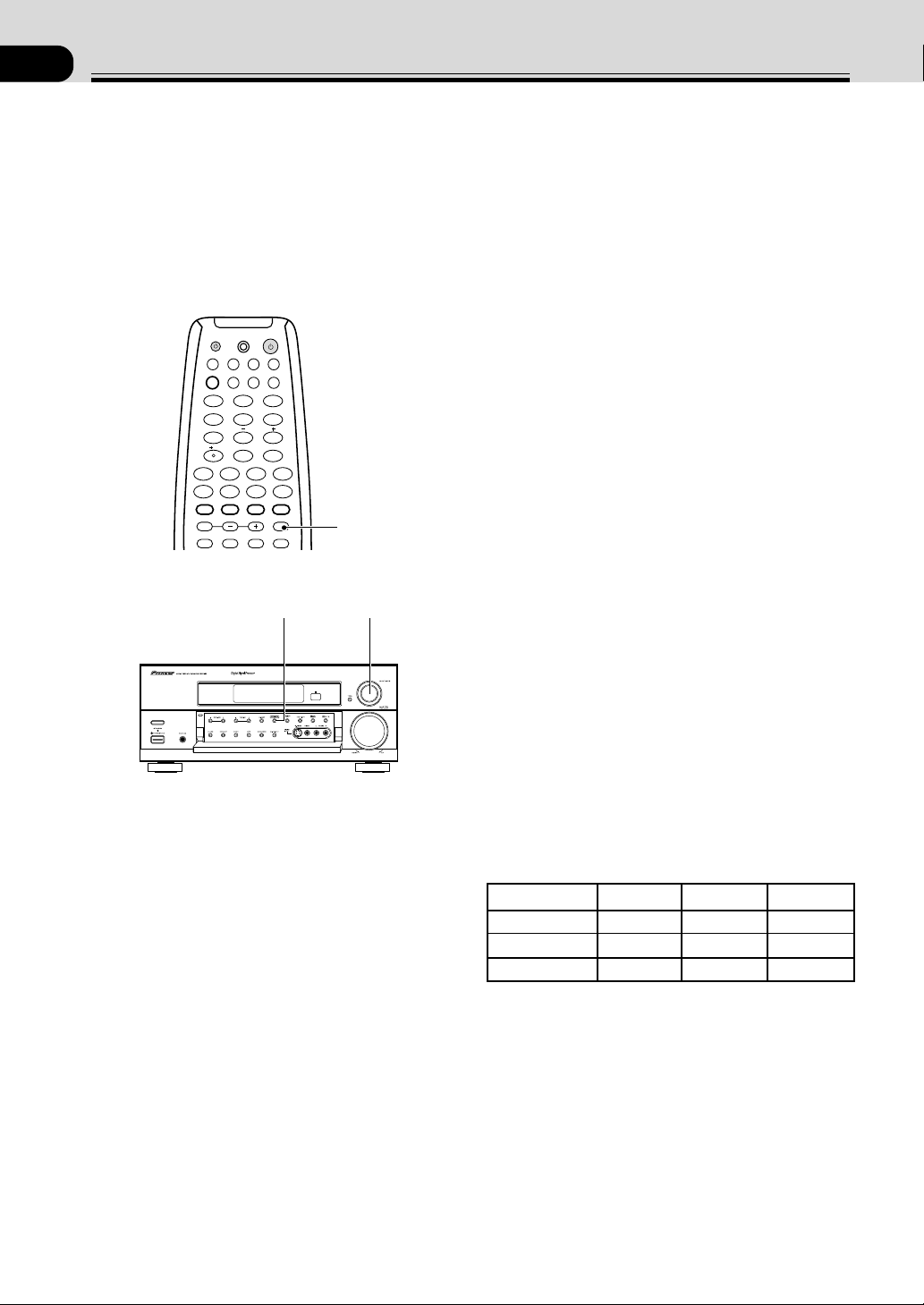
34
En
08
Making a Recording
Making an Audio or a Video
Recording
The following steps show you how to make an audio or
a video recording from the built in tuner, or from an
audio or video source connected to the receiver (such as
a CD player or TV). Recordings can be made to a CD-
Recorder, cassette deck, MD, VCR, or DVR deck
connected to the CD-R/TAPE/MD, VCR or DVR in/out
connectors.
1 Turn the MULTI JOG dial to select a source to
record (you can also use the MULTI
CONTROL
buttons if the DIRECT FUNCTION
is on).
All functions except MONITOR are accessible from
the remote control.
2 Prepare the program source.
Tune to the radio station, load the CD, etc. For a
video recording load the video, DVD etc.
3 Insert a blank tape, MD, video etc. into the
recording device connected to either CD-R/
MD/TAPE or VCR/DVR and set the recording
levels.
Refer to the instructions that came with the recorder
if you are unsure how to do this. Most video record-
ers set the audio recording level automatically—
check your video's instruction manual if you are
unsure whether yours has manual controls.
4 Start recording, then start playback of the
source component.
MEMO:
The receiver's volume, tone control (bass & treble)
loudness, and surround effects have no effect on the
recorded signal.
Record MONITOR
You can listen to (monitor) the recording as it's being
made using the MONITOR button on the front panel (a
cassette deck would have to have a record monitor
function).
Press the MONITOR button to switch between the
recorded signal and the original source signal.
Making a Digital Recording
The VSX-D710S has one optical digital output jack. The
VSX-D810S/D850S has one coaxial digital output jack
and one optical digital output jack. The quality of these
two types of connections is the same so you only need to
match the type of connection on this receiver with the
type of connection on your component. If you want to
make a digital recording from this receiver hook up the
optical output on this receiver to the optical input on the
digital component you want to record into. The source
component (like MD, CD, DVD, etc.) must be digital
also, of course, and hooked up to this receiver in a
digital manner. Make sure the analog/digital switch is set
to digital (see p. 29) The recording procedure is the
same as described above.
Refer to the table below for the type of digital connec-
tions available in each receiver model.
ENTER
DISC
DTV INFO
MPX/RETURN
DTV ON/OFF DTV MENU
D.ACCESS GUIDE
CLASS
ATT
BAND
/DTS DSP
TEST TONE
CH SELECT CH LEVEL FUNCTION
SIGNAL SELECT
1¡
4
¢
7
8
3
EFFECT
DVD VCR CD-RTV
RCV
TUN
TVC
CD
MIDNIGHT
LOUDNESS
MUTING
SETUP
FL DIMMER
MULTI CONTROL
5.1 / 7.1
RECEIVER
SOURCE
1
2
3
4
5
6
7
8
9
0
10
2
VSX-D710S
MONITOR
1
1
MODEL COAX IN OPT IN OPT OUT
VSX-D710S 1 2 1
VSX-D810S 1 3 1
VSX-D850S 1 4 1
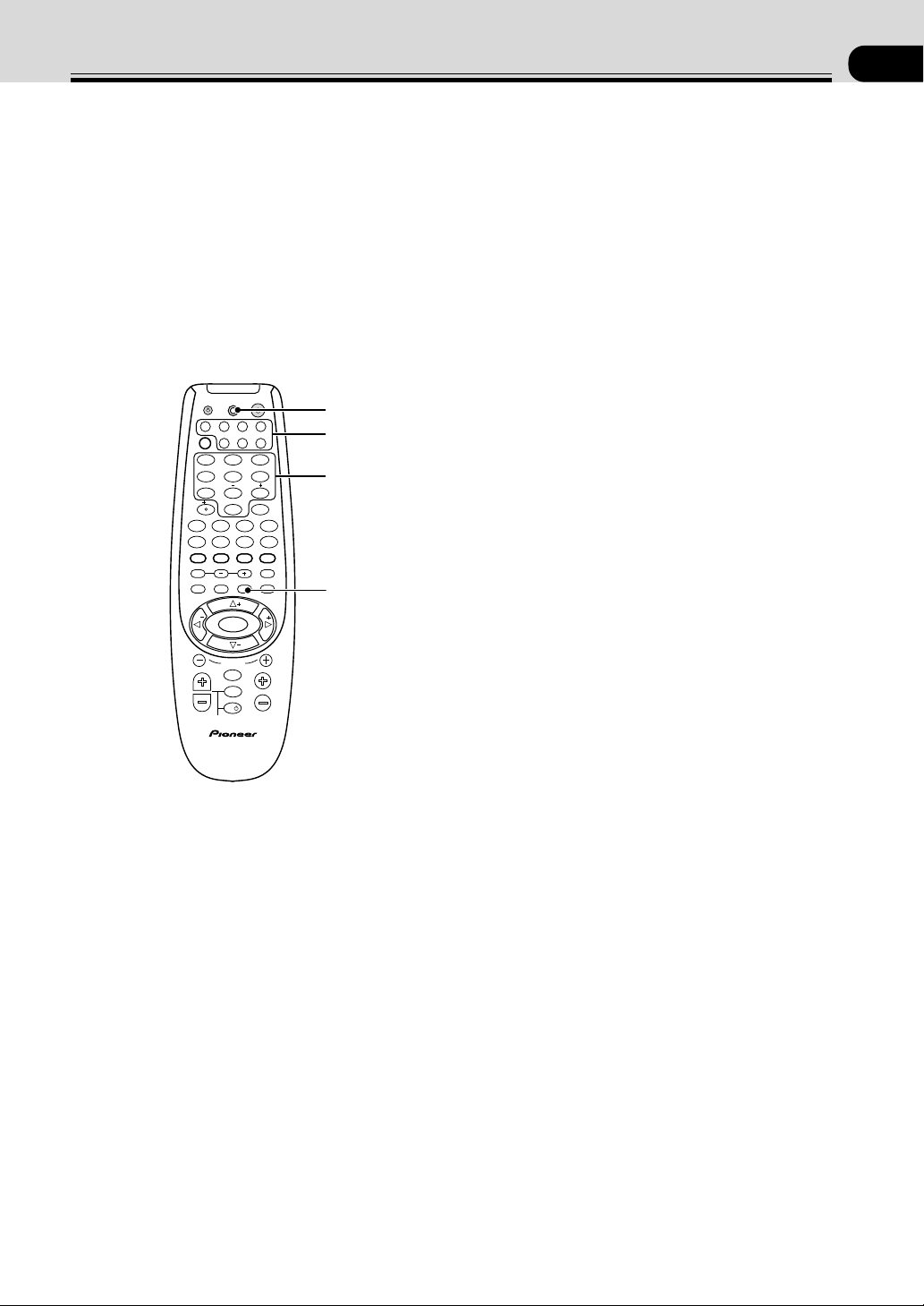
35
En
09
Controlling the Rest of Your System
Recalling Preset Codes
The following steps show you how to recall preset codes
for each MULTI CONTROL button. Once the preset
code is assigned, pressing the button will automatically
set the remote to operate the respective component.
MEMO:
• Refer to “Preset Code List” on pages 43 to 49 for the
components and manufacturers available.
• Refer to “Controlling the Rest of Your System” on
pages 35 to 49 for detailed explanations on how to
operate your other components.
1 Press SETUP and hold for three seconds to
select the Preset mode.
The LED lights steadily for two seconds. (VSX-
D850S only: The LCD display shows SETUP.)
To cancel the preset mode at any time
Press SETUP.
The remote control will also return to the previous
mode after thirty seconds of inactivity.
2 Press the MULTI CONTROL button for the
component you want to control.
Each button can be set to control one of the
following components
DVD DVD/LD player or DVD Recorder
TV TV, Satellite tuner or Cable TV tuner
VCR VCR or Digital Video Recorder
CD CD player
CD-R CD Recorder, Tape deck
or MD player
TVC TV or Cable TV tuner
TUN FM/ AM tuner
TV
TVFUNC
MENU
VOLUME
MASTER VOLUME
TV CONTROL
AV PRE-PROGRAMMED AND LEARNING
REMOTE CONTROL UNIT
CHANNEL
ENTER
ENTER
DISC
DTV INFO
MPX/RETURN
DTV ON/OFF DTV MENU
D.ACCESS GUIDE
ST
TUNE
TUNE
ST
CLASS
ATT
BAND
/DTS DSP
TEST TONE
CH SELECT CH LEVEL FUNCTION
SIGNAL SELECT
1¡
4
¢
7
8
3
EFFECT
DVD VCR CD-RTV
RCV
TUN
TVC
CD
MIDNIGHT
LOUDNESS
MUTING
SETUP
FL DIMMER
MULTI CONTROL
5.1 / 7.1
RECEIVER
SOURCE
1
2
3
4
56
7
8
9
0
10
2
3 Use the number buttons to enter the 4 digit
setup code. (see pages 43-49 for Preset Code
List)
The LED will blink for half a second after each digit
is input and will show a long, two second blink to
confirm a valid code has been input. (VSX-D850S
only: The code appears in the LCD display as you
input it. The display shows OK if it’s a valid code.)
If the LED blinks three times it means an invalid code
has been input or an error has occurred. Check the
preset code list and try again. If you are not able to
input a preset code you can refer to page 38 to teach
the remote control individual commands.
The remote control returns to the previous operation
mode. It will also return to the previous mode after
thirty seconds of inactivity.
4 Repeat steps 1 through 3 to assign preset
codes for as many components as necessary.
MEMO:
• You can only input a code for the component type
written on each MULTI CONTROL button.
• If you recall a preset code for the tuner (TUN MULTI
CONTROL), you will not be able to control the built-
in tuner of this receiver using the remote. To reset the
remote to the built-in tuner, input the preset code
7008.
• To erase the preset code for the current MULTI
CONTROL button, enter 0000 as the code in step 3.
1
3
2
LED
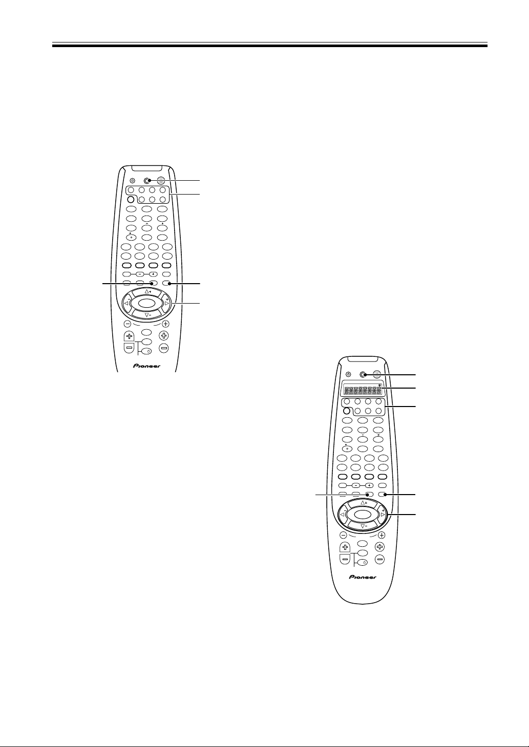
36
En
Setting Up Using Preset Code
Search (VSX-D710S/D810S)
An alternative method of setting up the remote with
preset codes is to use the search feature. The remote
transmits batches of 10 codes; when you see the
component responding you just scan through those last
10 codes until you find the correct one.
1 Switch on the component you want to
control.
If the component is some kind of player (CD player,
VCR, etc.), then start it playing.
2 Press and hold SETUP for three seconds.
The LED lights steadily for two seconds.
The remote control will also return to the previous
mode after thirty seconds of inactivity.
3 Press the MULTI CONTROL button for the
component you want to control.
Each button can be set to control one of the following
components
DVD DVD/LD player or DVD Recorder
TV TV, Satellite tuner or Cable TV tuner
VCR VCR or Digital Video Recorder
CD CD player
CD-R CD Recorder, Tape deck
or MD player
TVC TV or Cable TV tuner
TUN FM/ AM tuner
4 Press and hold SETUP for two seconds.
A batch of 10 codes is transmitted and the LED
blinks during transmission. If you see the component
respond, by stopping (for playback components
only) or switching off, go on to the step 5, otherwise
repeat this step.
If you want to cancel the search mode, press and
hold MUTING for two seconds.
Setting Up Using Full Library
Search (VSX-D850S)
An alternative method of setting up the remote with
preset codes is to use the Library Search feature. The
remote transmits batches of 10 codes; when you see the
component responding you just scan through those last
10 codes until you find the correct one.
1 Switch on the component you want to
control.
If the component is some kind of player (CD player,
VCR, etc.), then start it playing.
2 Press and hold SETUP for three seconds.
The remote’s LCD display shows SETUP.
The remote control will also return to the previous
mode after thirty seconds of inactivity.
Controlling the Rest of Your System
5 Switch the component back on or restart
playback.
6 Use the % fi buttons to scan through the last 10
codes transmitted to identify the correct code.
The LED will blink during transmission of the code.
Stop when you see the component stop or switch off.
You can also verify you have the correct code by
pressing PLAY, STOP., VOL +/–, etc.
7 Press and hold ENTER for three seconds to
save the preset code.
The remote control automatically returns to normal
usuage.
TV
TVFUNC
MENU
VOLUME
MASTER VOLUME
TV CONTROL
CHANNEL
ENTER
ENTER
DISC
DTV INFO
MPX/RETURN
DTV ON/OFF DTV MENU
D.ACCESS GUIDE
ST
TUNE
TUNE
ST
CLASS
ATT
BAND
/DTS DSP
TEST TONE
CH SELECT CH LEVEL FUNCTION
SIGNAL SELECT
1¡
4
¢
7
8
3
EFFECT
DVD VCR CD-RTV
RCV
TUN
TVC
CD
MIDNIGHT
LOUDNESS
MUTING
SETUP
FL DIMMER
MULTI CONTROL
5.1 / 7.1
RECEIVER
SOURCE
1
2
3
4
5
6
7
8
9
0
10
2
2,4
6,7
3
LED
2,5
3,7,8
4
LED
TV
TVFUNC
MENU
VOLUME
MASTER VOLUME
TV CONTROL
AV PRE-PROGRAMMED AND LEARNING
REMOTE CONTROL UNIT
CHANNEL
ENTER
ENTER
DISC
DTV INFO
MPX/RETURN
DTV ON/OFF DTV MENU
D.ACCESS GUIDE
ST
TUNE
TUNE
ST
CLASS
ATT
BAND
/DTS DSP
TEST TONE
CH SELECT CH LEVEL FUNCTION
SIGNAL SELECT
1¡
4
¢
7
8
3
EFFECT
DVD VCR CD-RTV
RCV
TUN
TVC
CD
MIDNIGHT
LOUDNESS
MUTING
SETUP
FL DIMMER
MULTI CONTROL
5.1 / 7.1
RECEIVER
SOURCE
1
2
3
4
5
6
7
8
9
0
10
2
SETUP
SEARCH SEARCH
BY BRAND
LEARN ERASE
LCD display
4
5

37
En
Setting Up Using Brand Name
Search (VSX-D850S only)
An alternative method of setting up the remote with
preset codes is to use the Brand Search feature. The
remote transmits batches of 10 codes; when you see the
component responding you just scan through those last
10 codes until you find the correct one.
1 Switch on the component you want to control.
If the component is some kind of player (CD player,
VCR, etc.), then start it playing.
Controlling the Rest of Your System
3 Use the @ # buttons to select the Full
Library Search mode.
The remote’s LCD display shows SEARCH.
4 Press the MULTI CONTROL button for the
component you want to control.
Each button can be set to control one of the following
components
DVD DVD/LD player or DVD Recorder
TV TV, Satellite tuner or Cable TV tuner
VCR VCR or Digital Video Recorder
CD CD player
CD-R CD Recorder, Tape deck
or MD player
TVC TV or Cable TV tuner
TUN FM/ AM tuner
5 Press and hold SETUP for two seconds.
A batch of 10 codes is transmitted and the LED
blinks during transmission.
If you see the component respond, by stopping (for
playback components only) or switching off, go on to
the step 6, otherwise repeat this step. After the ten
codes have been sent the search icon blinks.
If you want to cancel the search mode, press and
hold MUTING for two seconds.
6 Switch the component back on or restart
playback.
7 Use the % fi buttons to scan through the last
10 codes transmitted to identify the correct
code.
The transmission icon is on while the codes are sent
out. Stop when you see the component stop or
switch off. The LCD display shows the I.D.
You can also verify you have the correct code by
pressing PLAY, STOP., VOL +/–, etc.
8 Press and hold ENTER for three seconds to
save the preset code.
2 Press and hold SETUP for three seconds.
The remote’s LCD display shows SETUP.
The remote control will also return to the previous
mode after thirty seconds of inactivity.
3 Use the @ # buttons to select the Brand
Search mode, then press ENTER.
The remote’s LCD display shows BRAND SEARCH.
4 Press the MULTI CONTROL button for the
component you want to control.
Each button can be set to control one of the following
components
DVD DVD/LD player or DVD Recorder
TV TV, Satellite tuner or Cable TV tuner
VCR VCR or Digital Video Recorder
CD CD player
CD-R CD Recorder, Tape deck
or MD player
TVC TV or Cable TV tuner
TUN FM/ AM tuner
5 Use the % fi buttons to select the brand of
the component.
The brand names appear in the remote’s LCD display.
If the brand of your component doesn’t appear then
you can’t use this feature.
6 Press and hold SETUP for two seconds.
A batch of 10 codes is transmitted and the transmission
icon is on while the codes are sent out. After all ten
codes have been sent the search icon blinks.
If you see the component respond, by stopping (for
playback components only) or switching off, go on to
the step 6, otherwise repeat this step.
If you want to cancel the search mode, press and hold
MUTING for two seconds.
7 Switch the component back on or restart
playback.
8 Use the % fi buttons to scan through the last 10
codes transmitted to identify the correct code.
The transmission icon is on while the codes are sent
out. Stop when you see the component stop or
switch off. The display shows the I.D.
You can also verify you have the correct code by
pressing PLAY, STOP., VOL +/–, etc.
9 Press and hold ENTER for three seconds to
save the preset code.
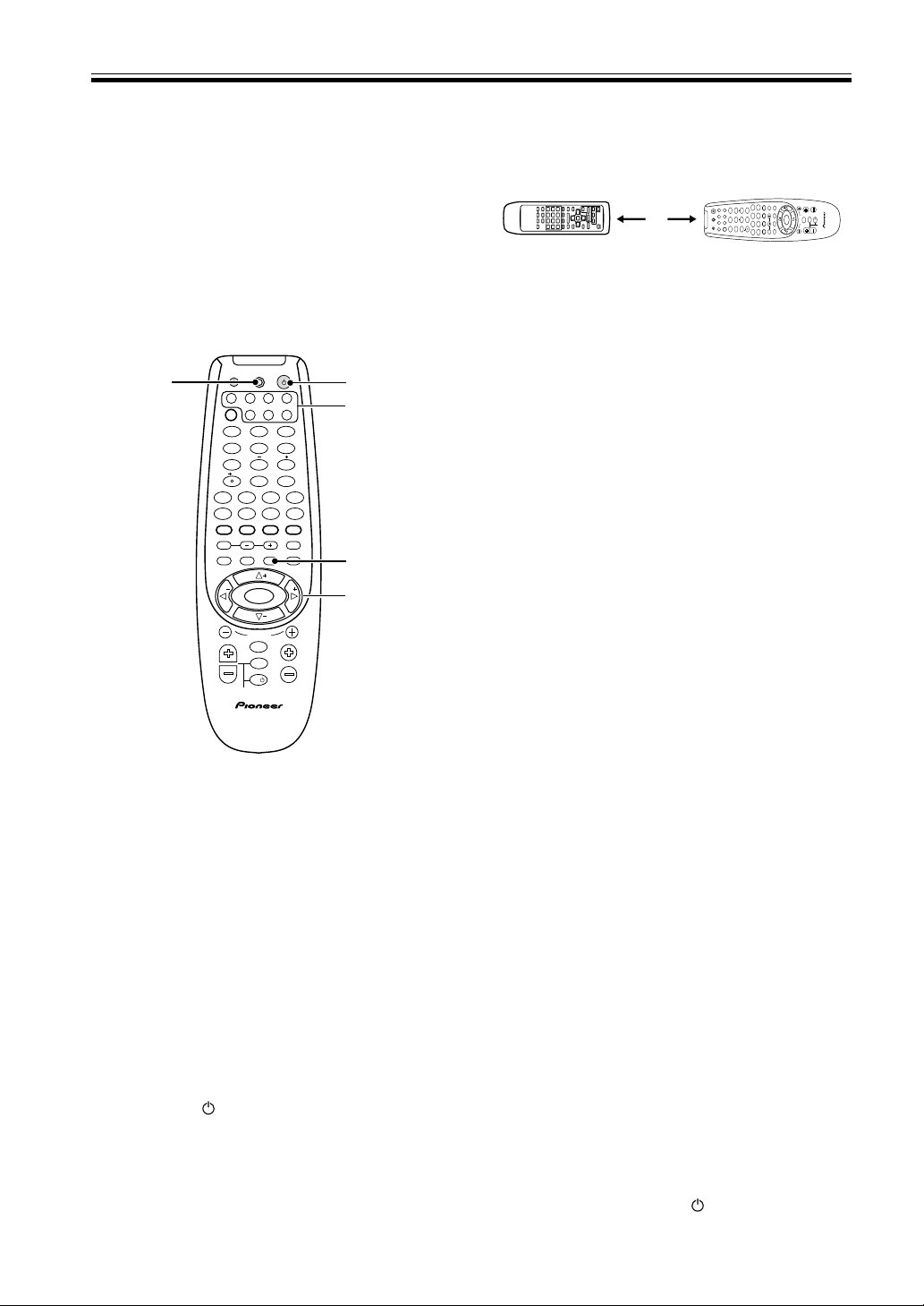
38
En
5 Point the two remote controls towards each
other. Press the button to be learned on this
receiver’s remote control (for example the 3
[play] button).
Point the remote controls directly at each other, about
1-2 inches apart, and press the button on the remote
control for the operation you want to program. The
LED flashes rapidly. For VSX-D850S, the LEARN icon
blinking.
6 Press the corresponding button on the other
remote control to be taught to this receiver’s
remote control (in the above example the 3
[play] button).
Point the remote controls toward each other.
Press the button on the other remote control
corresponding to the operation you wish to program.
The LED on this receiver’s remote will go out and
then resume a steady light if the operation is learned.
(For VSX-D850S model the LEARN icon will light
steadily and the LCD display will show “OK” if the
operation has been learned.) If the operation hasn’t
been learned for some reason the LED will blink for
three seconds and then light steadily. (For VSX-
D850S model the LCD will display “error” if the
operation hasn’t been learned.)
If this happens press the teaching key repeatedly,
varying the distances between the remotes, until you
see the LED on this unit’s remote light steadily,
without blinking first.
To program additional operations for the current
component
Repeat steps 5 and 6.
To program operations for another component
Repeat steps 2 through 6 (VSX-D850S).
Repeat steps 3 through 6 (VSX-D710S/D810S).
7 Press and hold SETUP for one second to exit
the LEARNING setup mode.
After thirty seconds of inactivity the remote control
will automatically leave the LEARNING mode and
revert to its previous mode.
MEMO:
• Some commands from other remote controls cannot
be learned, but in most cases the remotes just need to
be moved closer together or farther apart.
• Certain buttons represent modes that cannot be
learned from other remote controls. These include:
RCV, CH SELECT, CH LEVEL, FUNCTION
LOUDNESS, FL DIMMER, and MUTING.
• TV CONTROL buttons ( TV
, VOL +/-, and TV
FUNC ) can only be learned in TV & TVC mode.
Controlling the Rest of Your System
Learning Mode: Programming
Signals from other Remote
Controls
If preset codes are not available for your component(s),
or the available preset codes do not operate correctly,
you can use this function to program in signals from the
remote control(s) of your other component(s). This
operation can also be used after recalling a preset code
to program additional operations not covered in the
preset codes.
1 Press SETUP and hold for three seconds.
The LED on the remote control will light for two
seconds.
To cancel the Learning mode at any time
Press SETUP.
The remote control will also return to the previous
mode after thirty seconds of inactivity.
2 VSX-D850S only: Use the @ # buttons to
select the Learning mode.
The Learning mode is indicated by the Learning icon
(LEARN) in the remote’s LCD display.
3 Press the MULTI CONTROL button for the
component you want to control
4 VSX-D710S/D810S: Press and hold the
RECEIVER button for two seconds to start
the Learning mode.
The LED lights steadily.
To cancel LEARNING setup mode
Press SETUP for one second.
If no commands are entered within thirty seconds the
remote will revert to its previous mode.
TV
TVFUNC
MENU
VOLUME
MASTER VOLUME
TV CONTROL
AV PRE-PROGRAMMED AND LEARNING
REMOTE CONTROL UNIT
CHANNEL
ENTER
ENTER
DISC
DTV INFO
MPX/RETURN
DTV ON/OFF DTV MENU
D.ACCESS GUIDE
ST
TUNE
TUNE
ST
CLASS
ATT
BAND
/DTS DSP
TEST TONE
CH SELECT CH LEVEL FUNCTION
SIGNAL SELECT
1¡
4
¢
7
8
3
EFFECT
DVD VCR CD-RTV
RCV
TUN
TVC
CD
MIDNIGHT
LOUDNESS
MUTING
SETUP
FL DIMMER
MULTI CONTROL
5.1 / 7.1
RECEIVER
SOURCE
1
2
3
4
5
6
7
8
9
0
10
2
3
LED
2
4
1,7
VSX-D710S/
D810S only
VSX-D850S only
1 - 2 inches
TV
TVFUNC
MENU
VOLUME
MASTER VOLUME
TV CONTROL
AV PRE-PROGRAMMED AND LEARNING
REMOTE CONTROL UNIT
CHANNEL
ENTER
ENTER
DISC
DTV INFO
MPX/RETURN
DTV ON/OFF DTV MENU
D.ACCESS GUIDE
ST
TUNE
TUNE
ST
CLASS
ATT
BAND
/DTS DSP
TEST TONE
CH SELECT CH LEVEL FUNCTION
SIGNAL SELECT
1¡
4
¢
7
8
3
EFFECT
DVD VCR CD-RTV
RCV
TUN
TVCCD
MIDNIGHT
LOUDNESS
MUTING
SETUP
FL DIMMER
MULTI CONTROL
5.1 / 7.1
RECEIVER
SOURCE
1
2
3
4
56
7
8
9
0
10
2

39
En
Erasing One of the Remote
Control Button Settings
This erases one of the buttons you have programmed
and restores the factory installed preset to that button.
VSX-D710S/D810S:
1 Press SETUP and hold for three seconds.
The LED on the remote control will light for two
seconds.
2 Press the MULTI CONTROL button relating
to the function of the button to be cleared.
The remote control will return to the previous mode
after thirty seconds of inactivity.
3 Press the RECEIVER button twice within
three seconds to start erase mode.
The LED blinks.
4 Press the button to be cleared for three
seconds.
The LED lights steadily for three seconds and then
goes off.
5 Repeat steps 4 to erase other codes.
6 Press and hold the SETUP button for one
second to exit the erase mode.
VSX-D850S:
1 Press SETUP and hold for three seconds.
The LED on the remote control will light for two
seconds and the display shows SETUP.
2 Use the @ # buttons to select the Erase mode.
The LCD display shows ERASE.
3 Press the MULTI CONTROL button relating
to the function of the button to be cleared.
4 Press the button you want to clear.
5 Repeat steps 3-4 to erase other codes.
Clearing All the Remote
Control Settings
Clears all presets, all learned functions and restores the
factory presets.
1 Press SETUP and hold for three seconds.
For the VSX-D710S and VSX-D810S the LED on the
remote control lights for two seconds. For the VSX-
D850S the SETUP icon lights.
If you want to cancel the Clearing mode, press
SETUP.
The remote control will also return to the previous
mode after thirty seconds of inactivity.
Direct Function
The direct function is a useful feature which allows you
keep the receiver in one function (for example, CD)
while putting the remote control in a different function.
This could let you, for example, use the remote control
to set up and listen to a CD on the receiver and then use
the remote control to rewind a tape in your VCR while
you continue to listen to your CD player.
When the DIRECT function is ON any MULTI
CONTROL button you press will change the function of
both the receiver and the remote control. When you
turn the DIRECT function OFF, you can operate the
remote control without affecting the receiver. Thus you
could switch the remote control the VCR and operate
that component while the receiver plays a different
component.
To set a MULTI CONTROL button to DIRECT ON or
DIRECT OFF:
1 Press SETUP and hold for three seconds.
On the VSX-D710S and VSX-D810S the LED on the
remote control will light for two seconds. On the
VSX-D850S the LCD display SETUP icon will light.
If you want to cancel the Direct Function mode, press
SETUP.
The remote control will also return to the previous
mode after thirty seconds of inactivity.
2 Press the MULTI CONTROL button that you
want to set up.
3 Use the number buttons to enter 9990
(DIRECT ON) or 9995 (DIRECT OFF).
The LED will light for half a second on each digit
input. Then, on the VSX-D710S and VSX-D810S the
LED will light for two seconds to indicate that it’s
been correctly set. (If the LED blinks three times,
then you made a mistake with the code—try re-
entering it.) On the VSX-D850S, the LCD will display
“OK” to show the four digit code has been accepted.
If it hasn’t been accepted the display will blink three
times.
MEMO:
• TV CONT doesn’t have this feature and thus can’t use
the DIRECT FUNCTION.
Controlling the Rest of Your System
2 Use the number buttons to enter 0123.
The LED light for half a second for each digit input.
On the VSX-D710S and VSX-D810S the LED lights
for two seconds to indicate that the setings have been
restored to the factory presets. (If the LED blinks
three times, then you made a mistake with the
code—try re-entering it.) On the VSX-D850S the
LCD displays 0123 and then “OK” for two seconds if
the four digit code has been accepted. If any error has
occurred display will blink three times.
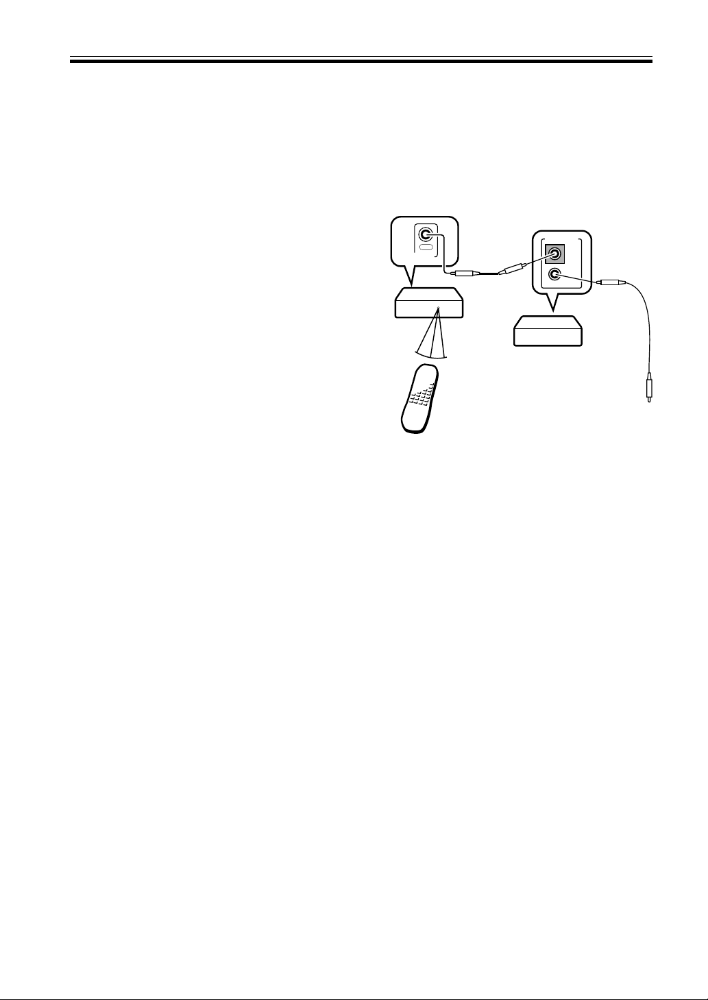
40
En
Checking Preset Codes
To check which preset code is associated with a MULTI
CONTROL button:
VSX-D710S/D810S:
1 Press SETUP and hold for three seconds.
The LED on the remote control lights for two
seconds.
2 Press the MULTI CONTROL button you
want to check the preset code for.
3 Press and hold ENTER for two seconds.
Each preset code consists of four digits, for example
1329. Each digit will be represented by a series of
blinks on the remote’s LED—3 blinks to represent
the digit “3”, etc. (“0” is represented by 10 blinks.)
VSX-D850S:
1 Press and hold for three seconds the MULTI
CONTROL button you want to check the
preset code for.
The preset code appears in the remote’s LCD display.
Controlling the Rest of Your System
Connect to CONTROL IN
terminal of other Pioneer
products with Î mark.
Remote control unit
VSX-D850S
Other Pioneer products
with Î mark
Operating other Pioneer
Components
By connecting a control cord (optional), you can control
other Pioneer equipment using this remote control unit.
Point the remote control unit towards the remote sensor
of this unit, even when operating other equipment.
The remote control signals are received by the remote
sensor of this unit, and sent to the other devices via the
CONTROL OUT terminal.
MEMO:
• You can also control Pioneer components by pointing
the receiver's remote control directly at the
component. This type of operation does not require
control cords.
CONTROL
OUT
OUT
IN
CONTROL
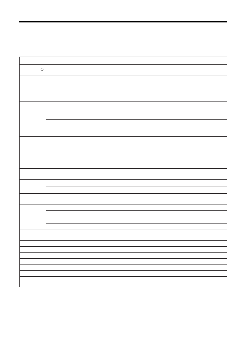
41
En
CD/MD/CD-R/VCR/DVD/LD/DVR Player/Cassette Deck Controls
This remote control can control these components after entering the proper codes or teaching the receiver the
commands (see p.35-37).
Use MULTI CONTROL buttons to put the remote control in the stated mode.
Controlling the Rest of Your System
)s(nottuBnoitcnuFstnenopmoC
ECRUOS.NOdnaYBDNATSneewtebstnenopmocehthctiwsotsserP
/DL/DVD/RCV/R-DC/DM/DC
kcedettessaC/reyalPRVD
ehtotspikssesserpdetaepeR.kcarttnerrucehtfotratsehtotnruterotsserP
.skcartsuoiverpfotrats
reyalPDL/DVD/R-DC/DM/DC
4 lennahc(slennahckcaboG − .)RVD/RCV
.kcedelbisreveranoepatehtfoedisesreverehtyalP kcedettessaC
ehtotspikssesserpdetaepeR.kcarttxenehtfotratsehtotecnavdaotsserP
.skcartgniwolloffotrats
reyalPDL/R-DC/DM/DC
¢ .)+lennahc(slennahcdrawrofoG RCV
.kcedelbisreveranoepatehtfoedisdrawrofehtyalP kcedettessaC
8 .gnidrocerrokcabyalpesuaP
/DL/DVD/RCV/R-DC/DM/DC
kcedettessaC/reyalPRVD
¡ .kcabyalpdrawroftsafrofnwoddloH
/DL/DVD/RCV/R-DC/DM/DC
kcedettessaC/reyalPRVD
1 .kcabyalpesrevertsafrofnwoddloH
/DL/DVD/RCV/R-DC/DM/DC
kcedettessaC/reyalPRVD
3 .kcabyalptratS
/DL/DVD/RCV/R-DC/DM/DC
kcedettessaC/reyalPRVD
7
ydaerlasicsidehtnehwsihtgnisserp,sledomemosno(kcabyalppotS
.)nepootyartcsidehtesuaclliwdeppots
/DL/DVD/RCV/R-DC/DM/DC
kcedettessaC/reyalPRVD
rebmuN
.ecruosmargorpanoskcartsseccayltceriD reyalPDL/RCV/R-DC/DM/DC
snottuB
.yalpsidneercs-noehtetagivanotsnottubrebmunehtesU reyalPRVD/DVD
nottuB01+
otrebmungniniamerehtdnanottubsihtsserP.01nahtrehgihskcarttceleS
.)31kcart=3+nottuB01+(kcartehtteg
reyalPDL/RCV/R-DC/DM/DC
nottuBCSID
.csidehtesoohC reyalpDCelpitluM
csidethtstcejE reyalPDM
.renutVTehtdnarenutRCVehtneewtebsehctiwsotsserP kcedettessaC/RCV
.DLehtfosedissegnahC reyalPDL
¶ DROCER
nottuB
desserpebtsumnottubsiht,gnidrocerlatnediccatneverpoT.gnidrocertratS
.)tsrifehtfosdnoces01nihtiwebtsumsserpdnoceseht(tceffeekatoteciwt
reyalPRVD/RCV
UNEM .gnisuerauoyRVDroDVDtnerrucehtgninrecnocsunemsyalpsiD reyalPRVD/DVD
% .epatehtesuaP kcedettessaC
fi .epatehtpotS kcedettessaC
RETNE.kcabyalptratS kcedettessaC
@ .epatehtdniwertsaF kcedettessaC
# epatehtdrawroftsaF kcedettessaC
fi%#@ &
RETNE
.snoitpo/sunemDVDetagivaN reyalPRVD/DVD
42
En
Cable TV/Satellite TV/TV/DTV Controls
This remote control can control these components after entering the proper codes or teaching the receiver the
commands (see p.35-37).
Use MULTI CONTROL buttons to put the remote control in the stated mode.
MEMO:
• The first four buttons for the VSX-D710S/D810S/D850S are dedicated to control the TV assigned to the
TVC
button. Thus if you only have one TV to hook up to this system assign it to the TVC MULTI CONTROL button. If
you have two TVs, assign the main TV to the TVC button. If you hook up your system this way, the first four TV
controls will always be accessible.
Controlling the Rest of Your System
)s(nottuBnoitcnuFstnenopmoC
VT
.fforonoVTDehthctiwsotsserP VTD
.NOdnaYBDNATSneewtebVTACroVTehthctiwsotsserP VT/VTetilletaS/VTelbaC
.CNUFVT
krowt'nseodtifI.sledomllahtiwelbissoptoN(.tupniVTehthctiwsotsserP
).erutaefgninraelehtesu,edocteserpehthtiw
VT
LENNAHC
/+ −
.slennahctceleS VTD/VT/VTetilletaS/VTelbaC
/+LOVVT − .emulovVTehttsujdA VTD/VT/VTetilletaS/VTelbaC
ECRUOS
.fforonoVTDehthctiwsotsserP VTD
4
slennahcderebmunrewolotevoM VT/VTetilletaS/VTelbaC
.unemVTDanosdnammocDERehtesoohC VTD
¢
slennahcderebmunrehgihotevomotesU VT/VTetilletaS/VTelbaC
.unemVTDanosdnammocWOLLEYehtesoohcotesU VTD
8 gnitagivanrofnottubEDIUGehtsaesU VTD
¡ .unemVTDanosdnammocNEERGehtesoohcotesU VTD
1 .unemVTDanosdnammocEULBehtesoohcotesU VTD
3 .margorpVTDehtnoOFNItegotesU VTD
7 skcartoiduaVTDhctiwsotesU VTD
rebmuN
snottuB
.lennahcVTcificepsatcelesotesU VTD/VT/VTetilletaS/VTelbaC
nottuB01+ .lennahcVTcificepsagnitcelesnehwtnioplamicedaddaotesU VTD
nottuBCSID
.lennahcaretneotesU VTD
UNEM.snoitcnufVTDehtmorfsunemtnereffidtceleS VTD
.neercsunemehttceleS VT/VTetilletaS/VTelbaC
fi%#@ &
.neercsunemehtnosmetietagivandnatsujdarotceleS
.sunemVTDehtpugnirbotesU:RETNE
VTD
RETNE.neercsunemehtnosmetietagivandnatsujdarotcelesotsserP VTD/VT/VTetilletaS/VTelbaC
/+TCEFFE −
lennahcwenaretneyletaidemmiotnottubsihtesuVTelbacdnaVTroF
ehttixeotnottubsihtesuVTetilletasroF.)noitcnufRETNELENNAHC(
.neercsunem
VTD/VT/VTetilletaS/VTelbaC

43
En
Preset Code List
You can only set these codes for the buttons that assigned to the respective components. So, for example, the
TV codes can only be set to the TV or TVC button.
Controlling the Rest of Your System
TV
Manufacturer Code
PHILIPS 1008, 1017, 1020
1025, 1104, 1115
SONY 1001, 1007, 1016
PANASONIC 1023, 1054, 1055
1075, 1076, 1082
1087, 1121, 1124
TOSHIBA 1015, 1016, 1027
1031, 1050, 1051
1085
TELEFUNKEN 1005, 1026, 1034
1038, 1042, 1046
1075, 1097
SHARP 1016, 1019, 1041
1056, 1124
SAMSUNG 1006, 1011, 1013
1017, 1026, 1027
1039, 1062, 1079
1089, 1092, 1102
FERGUSON 1005, 1017, 1033
1046, 1065, 1084
1091
MITSUBISHI 1011, 1016, 1041
1045, 1049, 1062
1114
GOLDSTAR 1002, 1011, 1013
1017, 1019, 1026
1046, 1062, 1079
1092
BLAUPUNKT 1066, 1068, 1071
1075, 1115
RADIOLA 1008, 1017
JVC 1016, 1024, 1030
1053, 1065, 1067
1103, 1122
DAEWOO 1006, 1011, 1017
1019, 1028, 1040
1050, 1104, 1110
1118, 1119
ORION 1017, 1063, 1083
1095, 1098, 1099
1112
SIEMENS 1017, 1052, 1066
1068, 1071, 1075
1115
ADMIRAL 1041, 1055, 1075
1112
ADYSON 1014, 1079
AIKO 1040
AKAI 1013, 1074
AKURA 1080, 1089
ACURA 1006
ALARON 1063, 1078
ALBA 1006, 1016, 1017
1080, 1103
ALLORGAN 1095
ANAM 1004, 1006, 1029
1054, 1064, 1087
1108
ANAM NATIONAL 1054, 1087, 1108
AMBASSADOR 1061
AMERICA ACTION 1064
AMPLIVISION 1079
AMPRO 1126
AMSTRAD 1006, 1017, 1103
1105
ANITECH 1006, 1029, 1036
AOC 1011, 1013
ARCAM 1078, 1079
ASBERG 1036
ASUKA 1080
ATLANTIC 1073
AUDIOSONIC 1017, 1046
AUDIOVOX 1040, 1064, 1110
1118
AUTOVOX 1036, 1073
BANG & OLUFSEN 1116
BASIC LINE 1006, 1080
BAYSONIC 1064
BAUR 1007, 1017, 1114
1115
BEKO 1102
BELCOR 1011
BELL & HOWELL 1009, 1050
BEON 1017
BINATONE 1079
BLUE SKY 1080
BLUE STAR 1090
BONDSTEC 1086
BOOTS 1079
BPL 1090
BSR 1095
BRADFORD 1064
BRANDT 1046, 1069, 1070
1072
BRITANNIA 1078
BROCKWOOD 1011
BROKSONIC 1083, 1112
BTC 1080
BUSH 1006, 1016, 1017
1080, 1090, 1095
1103, 1104
CANDLE 1013, 1026
CARNIVALE 1013
CARREFOUR 1016
CARVER 1025, 1058
CASCADE 1006
CATHAY 1017
CENTURY 1075
CENTURION 1017
CELEBRITY 1001
CCE 1017
CGE 1034, 1036, 1038
1086, 1097
CIMLINE 1006
CINERAL 1040, 1110
CITIZEN 1013, 1019, 1026
1027, 1040
CLARIVOX 1017
CLATRONIC 1036, 1086, 1102
CME 1007, 1015, 1114
CONCERTO 1026
CONDOR 1098, 1102
CONTEC 1006, 1016, 1064
1078
CONTINENTAL EDISON 1069, 1070
1072
CRAIG 1054
CROSLEY 1025, 1034, 1036
1038, 1075
CROWN 1006, 1017, 1019
1036, 1064, 1102
1106
CRYSTAL 1109
CS ELECTRONICS 1078
CTC 1086
CURTIS MATHES 1009, 1013, 1019
1022, 1023, 1025
1026, 1027, 1041
1047, 1050, 1057
1110, 1113, 1129
1131
CYBERTRON 1080
CXC 1064
DAINICHI 1077, 1080
DANSAI 1017
DAYTRON 1006, 1011
DECCA 1017, 1032
DE GRAAF 1074
DENON 1047
DIXI 1006, 1017
DUAL TEC 1079
DUMONT 1010, 1011, 1031
DWIN 1125, 1127
ECE 1017
ELBE 1088
ELECTROBAND 1001
ELIN 1017
ELITE 1080, 1098
ELTA 1006
EMERSON 1011, 1018, 1019
1050, 1061, 1062
1063, 1064, 1075
1083, 1090, 1112
1118, 1119
ENVISION 1013
ERRES 1008, 1017
ETRON 1006, 1120
EXPERT 1073
FIDELITY 1078
FINLANDIA 1074
FINLUX 1017, 1031, 1032
1044
FISHER 1050, 1074, 1079
1096, 1102
FLINT 1111
FORMENTI 1017, 1075, 1098
FORTRESS 1041
FRONTECH 1055, 1086, 1089
1109
FUJITSU 1032, 1063, 1073
FUNAI 1059, 1063, 1064
1089, 1095, 1096
FUTURETECH 1064
GE 1012, 1022, 1023
1041, 1062, 1090
1110, 1129, 1131
GEC 1017, 1020, 1032
1072, 1079
GELOSO 1006, 1075
GENEXXA 1055, 1080
GIBRALTER 1010, 1011, 1013
GOODMANS 1016, 1017, 1032
1079, 1103, 1104
GORENJE 1102
GPM 1080
GRAETZ 1055
GRANADA 1017, 1032, 1048
1074, 1079, 1100
GRADIENTE 1024, 1026, 1058
GRANDIN 1090
TV
TVC

44
En
Controlling the Rest of Your System
GRUNDIG 1031, 1066, 1068
1072, 1115
GRUNPY 1063, 1064
HALLMARK 1062
HANSEATIC 1017, 1098
HARLEY DAVIDSON 1063
HARVARD 1029, 1064
HARMAN/KARDON 1025
HCM 1006, 1090, 1105
HINARI 1006, 1016, 1017
1080
HISAWA 1090, 1111
HITACHI 1014, 1016, 1018
1020, 1021, 1026
1044, 1046, 1047
1055, 1069, 1070
1079, 1081, 1097
HUANYU 1078, 1104
HYPSON 1017, 1089, 1090
ICE 1079, 1089, 1103
ICES 1080
IMPERIAL 1034, 1036, 1038
1086, 1102, 1106
INDIANA 1017
INFINITY 1025
INGELEN 1055
INNO HIT 1032
INNOVA 1017
INTEQ 1010
INTERBUY 1029
INTERFUNK 1017, 1055, 1086
1114
INTERVISION 1017, 1029, 1043
1079, 1089
ISUKAI 1080
ITS 1103
ITT 1055
JBL 1025
JCB 1001
KAISUI 1006, 1078, 1079
1080, 1090,
KAMP 1078
KAPSCH 1055, 1073
KAWASHO 1078
KEC 1064
KENDO 1017
KNEISSEL 1088
KENWOOD 1011, 1013
KINGSLEY 1078
KONIG 1114
KORPEL 1017
KOYODA 1006
KTV 1013, 1019, 1064
LEYCO 1017, 1032, 1089
1095
LG 1026
LIESENK&TTER 1017
LLOYTRON 1014
LOEWE 1035, 1114
LOGIK 1009
LUMA 1073
LUXMAN 1026
LXI 1022, 1025, 1050
1051, 1062
M ELECTRONIC 1006, 1017, 1029
1044, 1046, 1055
1079, 1091, 1104
MAGNAVOX 1013, 1016, 1025
1063
MAGNADYNE 1043, 1086
MAGNAFON 1036, 1043, 1075
MAJESTIC 1009
MANESTH 1079, 1089, 1098
MARANTZ 1013, 1017, 1025
MARK 1017
MATSUI 1006, 1015, 1016
1017, 1032, 1074,
1079, 1095, 1103
MATSUSHITA 1087
MCMICHAEL 1020
MEDIATOR 1008, 1017
MEGATRON 1047, 1062
MEMOREX 1006, 1009, 1026
1049, 1050, 1062
1087, 1112
METZ 1075
MGA 1011, 1013, 1049
1062
MIDLAND 1010, 1019, 1022
1023
MINERVA 1031, 1115
MINOKA 1105
MINUTZ 1012
MIVAR 1078, 1092, 1093
1094
MOTION 1036
MOTOROLA 1041
MTC 1011, 1013, 1026
1027, 1078, 1114
MULTITECH 1006, 1036, 1043
1064, 1078
NAD 1051, 1057, 1062
NEC 1011, 1013, 1016
1026, 1058
NECKERMANN 1017, 1066, 1075
1115
NEI 1017, 1109
NETSAT 1017
NICAMAGIC 1078
NIKKAI 1014, 1015, 1017
1032, 1078, 1080
1089
NIKKO 1013, 1040, 1062
NOBLIKO 1036, 1043
NORDMENDE 1046, 1069, 1070
1075, 1091
NTC 1040
OCEANIC 1055, 1077
ONWA 1064
OPTIMUS 1050, 1057, 1087
OPTONICA 1041, 1056
OSAKI 1014, 1032, 1079
1080, 1089, 1105
OSO 1080
OSUME 1014, 1032, 1052
OTTO 1007, 1114
OTTO VERSAND 1007, 1016, 1017
1066, 1075, 1079
1098, 1115
PALLADIUM 1102, 1106
PANAMA 1079, 1089
PATHE MARCONI 1069, 1070, 1072
PATHE CINEMA 1075, 1078, 1084
1098
PAUSA 1006
PENNEY 1003, 1011, 1012
1013, 1019, 1022
1023, 1026, 1027
1051, 1062, 1131
PERDIO 1098
PHAPSODY 1078
PHASE 1014
PHILCO 1011, 1013, 1025
1034, 1036, 1038
1047, 1075, 1086
1112
PHONOLA 1008, 1017
PILOT 1011, 1013, 1019
PORTLAND 1011, 1019, 1040
PRISM 1023
PROFEX 1006, 1037
PROLINE 1099
PROSOCAN 1022
PROTECH 1006, 1017, 1043
1079, 1086, 1089
1106, 1109
PROTON 1062, 1113
PULSAR 1010, 1011
PYE 1008
QUASAR 1023, 1056, 1087
QUELLE 1007, 1017, 1031
1034, 1038, 1071
1075, 1097, 1114
1115
QUESTA 1016
R-LINE 1017
RANK ARENA 1016
RBM 1031
RCA 1011, 1018, 1022
1023, 1039, 1041
1128, 1129, 1130
1131, 1132
REALISTIC 1011, 1013, 1019
1026, 1050, 1056
1062, 1064
REX 1055, 1073, 1088
1089
REVOX 1017
ROADSTAR 1006, 1080, 1089
1106
RUNCO 1010, 1013, 1117
SABA 1035, 1046, 1055
1069, 1070, 1072
1075, 1091
SACCS 1084
SAISHO 1006, 1089, 1109
SALORA 1055
SAMBERS 1036, 1043, 1075
SAMPO 1013, 1019
SAMSUX 1019
SANDRA 1078
SANSEI 1110
SANSUI 1112
SANYO 1016, 1032, 1048
1050, 1052, 1074
1075, 1100
SBR 1008, 1017, 1020
SCHNEIDER 1017, 1080, 1086
1096, 1103
SCIMITSU 1011
SCOTCH 1062
SCOTT 1011, 1062, 1063
1064, 1083
SEARS 1022, 1025, 1026
1050, 1051, 1059
1062, 1063
SEG 1016, 1036, 1079
1089
SEI 1043, 1075, 1095
SEI-SINUDYNE 1007
SELECO 1055, 1073, 1088
SEMIVOX 1064
SEMP 1051
SENTRA 1015
SHOGUN 1011
SHORAI 1095
SSS 1011, 1064
SIAREM 1043, 1075

45
En
SINDYNE 1043, 1075, 1095
SIGNATURE 1009
SILVER 1016
SKY 1017
SKY-WORTH 1017
SOLAVOX 1014, 1055
SONITRON 1074
SONOKO 1006, 1017
SONOLOR 1055, 1074, 1077
SONTEC 1017
SOUNDESIGN 1062, 1063, 1064
SOUNDWAVE 1017, 1106
SQUAREVIEW 1059
STANDARD 1006, 1079, 1080
STARLITE 1064
STERN 1055, 1073, 1088
SUNKAI 1095, 1099
SUPERTECH 1078
SUPREME 1001
SUSUMU 1080
SYLVANIA 1013, 1025
SYMPHONIC 1059
SYSLINE 1017
TANDY 1032, 1041, 1055
1079, 1080
TASHIKO 1016, 1020, 1079
TEC 1079, 1086
TECHNEMA 1098
TECHNICS 1023, 1087, 1121
TECHNOL ACE 1063
TECHWOOD 1023, 1026
TEKNIKA 1009, 1011, 1019
1025, 1026, 1027
1040, 1049, 1063
1064
TELEAVIA 1072
TELEMEISTER 1098
TELETECH 1006
TELETON 1016, 1073, 1079
TENSAI 1080, 1095, 1098
TEXET 1078, 1080
THOMSON 1046, 1069, 1070
1072, 1091
THORN 1015, 1017, 1032
1034, 1038, 1065
1067, 1114
TMK 1026, 1061, 1062
TOMASHI 1090
TOTEVISION 1019
TRIUMPH 1085
TUTUNG 1017, 1032, 1079
UHER 1073, 1096, 1098
ULTRA 1067
ULTRAVOX 1043
UNIVERSUM 1017, 1044, 1089
1102
VECTOR RESEARCH 1013
VESTEL 1017
VICTOR 1016, 1024, 1053
1087
VIDEOSAT 1086
VIDEOTECHNIC 1079
VIDIKRON 1025
VIDTECH 1011, 1016, 1062
VISION 1098
VOXSON 1055
WALTHAM 1079
WATSON 1017, 1098
WATT RADIO 1043
WARDS 1009, 1011, 1012
1013, 1025, 1026
1056, 1062, 1063
WEGA 1016
WHITE WESTINGHOUSE 1017, 1078
1098, 1112, 1118
1119
YAMAHA 1011, 1013
YOKO 1017, 1079, 1101
1109
ZANUSSI 1073
ZENITH 1009, 1010, 1040
1112
PIONEER 1018, 1046, 1055
1057, 1060, 1091
1107, 1123, 1124
MD PLAYER
Manufacturer Code
SONY 5401
KENWOOD 5402,5407
SHARP 5403
ONKYO 5404
ORION 5406
DENON 5405
PIONEER 5408
LD PLAYER
Manufacturer Code
AKAI 5222
BBK 5224
CYRUS 5207
DENON 5202
DISCO VISION 5201
FUNAI 5217
HITACHI 5201
HONG DENG 5213
IDALL 5219
KEBAO 5215
MARANTZ 5203, 5205
MITSUBISHI 5202
NAD 5202
PANASONIC 5210
PHILIPS 5203, 5207, 5209
RADIOLA 5207
ROWA 5212
SALORA 5203
SEGA 5201
SHARP 5221
SHINCO 5211
SMC 5220
SONY 5204, 5206, 5216
5218
SUPER 5215
TELEFUNKEN 5202
TOSHIBA 5223
PIONEER 5201,5202, 5208
5214
Controlling the Rest of Your System
CD PLAYER
Manufacturer Code
AIWA 5016, 5021
AKAI 5014, 5020, 5032
ANAM 5041
ARCAM 5021
AUDIOLAB 5021
AUDIOMECA 5021
AUDIO TON 5021
BESTAR 5022
BURMESTER 5045
CALIFORNIA AUDIO LABS 5004
CARVER 5021, 5025, 5046
CONDOR 5018, 5022
CURTIS MATHES 5004
CYRUS 5021
DENON 5002, 5006, 5040
5060
DKK 5001
DUAL 5031
DYNAMIC BASS 5025
EMERSON 5038
EROICA 5053, 5054
FANTASIA 5051
FISHER 5024, 5025
GARRARD 5044, 5045
GENEXXA 5005, 5038
GOLDSTAR 5043, 5051
GRUNDIG 5021
HARMAN/KARDON 5021, 5023
HITACHI 5005
INKEL 5015, 5026, 5046
JVC 5011
KENWOOD 5003, 5008, 5029
5056, 5057, 5062
KRELL 5021
LINN 5021
LUXMAN 5036
LXI 5038
MAGNAVOX 5021, 5038
MARANTZ 5004, 5009, 5017
5021, 5026
MATSUI 5021
MCS 5004
MEMOREX 5022
MERIDIAN 5021
MICROMEGA 5021
MISSION 5021
MITSUBISHI 5014, 5020
MTC 5045
NAD 5001
NAIM 5021
NIKKO 5024, 5041, 5051
NSM 5021
ONKYO 5012, 5013, 5042
5059
OPTIMUS 5001, 5005, 5008
5019, 5025, 5038
5045, 5046, 5048
ORION 5061
PANASONIC 5004, 5037
PARASOUND 5045
PHILIPS 5021, 5055
PMG 5022
POPPY 5022
PROTON 5021
QED 5021
QUAD 5021
QUASAR 5004,
RCA 5010, 5025, 5038
CD-R
CD
DVD
CD-R
CD
46
En
Controlling the Rest of Your System
REALISTIC 5025, 5026, 5045
REVOX 5021
ROTEL 5021, 5045
SAE 5021
SANSUI 5021, 5033, 5038
SANYO 5025, 5039
SCHNEIDER 5018
SCOTT 5038
SEARS 5038
SHARP 5008, 5026, 5058
SHERWOOD 5015, 5026, 5031
SONY 5001, 5027, 5050
SOUDESIGN 5019
TASCAM 5045
TEAC 5024, 5026, 5044
5045
TECHNICS 5004, 5034, 5037
THORENS 5021
TOSHIBA 5049
UNIVERSUM 5021
YAMAHA 5007, 5028
YORX 5047
VICTOR 5011
WARDS 5010, 5021
PIONEER 5005, 5030, 5035
5038, 5048, 5052
5063
TAPE DECK
Manufacturer Code
ADC 6013
AIWA 6002, 6022, 6017
6018
AKAI 6015, 6016
ANAM 6035
ARCAM 6005
CARVER 6002, 6028
DENON 6005, 6039
DUAL 6037
DYNAMIC BASS 6028
EROICA 6041
FISHER 6028
GARRARD 6036
GOLDSTAR 6036
GRUNDIG 6002
HARMON/KARDON 6002, 6014
INKEL 6003
JVC 6027, 6030, 6031
KENWOOD 6003, 6004, 6019
6024, 6025
KYOCERA 6013
LOTTE 6034
LUXMAN 6029
MAGNAVOX 6002
MARANTZ 6002
MEMOREX 6008, 6009
MITSUBISHI 6016
NAKAMICHI 6020
NIKKO 6035
OLYMPUS 6029
ONKYO 6010, 6011, 6032
OPTIMUS 6001, 6021
PANASONIC 6023
PHILIPS 6002
RCA 6028
RENAISSANCE 6040
REVOX 6002
MISC AUDIO
Manufacturer Code
JERROLD 8201, 8203
STARCOM 8201
SCIENTIFIC ATLANTA 8202
SAMSUNG 6038
SANSUI 6002
SANYO 6028
SHARP 6019
SONIC 6036
SONY 6012, 6026, 6033
TEAC 6038
TECHNICS 6023
THORENS 6002
VICTOR 6027, 6030
WARDS 6001
YAMAHA 6006, 6007, 6019
PIONEER 6001, 6008, 6009
6021,
DVD PLAYER
Manufacturer Code
TOSHIBA 5302
SONY 5306
PANASONIC 5301, 5322
KENWOOD 5307
JVC 5311, 5318
SAMSUNG 5313
AKAI 5316
HARMAN/KARDON 5314
MAGNAVOX 5302
MITSUBISHI 5303
ONKYO 5302, 5317, 5319
PROSCAN 5304
RCA 5304
SHARP 5320
THETA DIGITAL 5312
TECHNICS 5301
THOMSON 5310
YAMAHA 5301, 5309
PHILIPS 5302, 5308
ZENITH 5302, 5315
PIONEER 5305, 5312, 5321
5322
AMPLIFIER
Manufacturer Code
AUDIOLAB 8005
DENON 8002
GRUNDIG 8005
MARANTZ 8005
MICROMEGA 8005
PHILIPS 8005
PIONEER 8004
REVOX 8005
TANDBERG 8003
THORENS 8005
YAMAHA 8001, 8006
RECEIVERS
Manufacturer Code
ADC 7042
AIWA 7012, 7023, 7031
7055, 7064
AKAI 7011, 7027
ANAM 7010, 7046
ARCAM 7018, 7048
AUDIOLAB 7059
CAPETRONIC 7042
CARVER 7055, 7059
CURTIS 7008
DAEWOO 7032
DENON 7001, 7056, 7058
DUAL 7040
EROICA 7005
FANTASIA 7037
FERGUSON 7042
FINE ARTS 7059
FISHER 7028
GARRARD 7032, 7034, 7035
GOLDSTAR 7010
GOODMANS 7027
GP AUDIO 7033
GRUNDIG 7018, 7059
HARMAN/KARDON 7009, 7051
INKEL 7038, 7040
JBL 7009
JVC 7007, 7036, 7042
KENWOOD 7003, 7017, 7025
7026, 7044, 7053
7063, 7066
LOTTE 7037, 7039
LUXMAN 7021
MAGNAVOX 7030, 7042, 7055
7059
MARANTZ 7004, 7018, 7055
7059
MCINTOSH 7020
MCS 7004
MCSILVER 7037
MICROMEGE 7018, 7059
NIKKO 7032, 7037, 7046
OPTIMUS 7017, 7034, 7042
7049, 7052
ONKYO 7013, 7029
PALLADIUM 7050
PANASONIC 7004, 7024, 7041
PHILIPS 7018, 7030, 7045
7048, 7051, 7055
7059
PHONOTREND 7038
QUASAR 7004
RCA 7006, 7042
RENAISSANCE 7043
REVOX 7018
ROADSTAR 7027
SABA 7042
SAISHO 7027
SAMSUNG 7010
SANSUI 7027, 7055
SANYO 7028
CD-R
CD
DVD
TUN
TUN
TUN

47
En
FISHER 2025, 2026, 2030
2037
FRONTECH 2011
FUJI 2015
FUNAI 2001
GARRARD 2001
GE 2015, 2027, 2032
2057
GEC 2035
GENERAL 2011, 2028
GOLDHAND 2034
GOLDSTAR 2017, 2018, 2053
2079
GOODMANS 2001, 2017, 2034
2059, 2075
GO VIDEO 2077, 2081
GRAETZ 2005, 2021, 2037
2057
GRANADA 2025, 2035, 2037
GRADIENTE 2001, 2008
GRANDIN 2001, 2017, 2034
HANSEATIC 2017
HARMAN/KARDON 2018, 2035
HARLEY DAVIDSON 2001
HARWOOD 2034
HCM 2034
HEADQUARTER 2025
HINARI 2004, 2034, 2057
2072
HI-Q 2026
HUGHES NETWORK SYSTEMS 2022
HYPSON 2034
IMPERIAL 2001
INGERSOL 2004
INTERFUNK 2035
ITT 2005, 2021, 2025
2037, 2038, 2057
2074
ITV 2017, 2059
JENSEN 2021
KAISUI 2034
KEC 2017, 2059
KENDO 2038, 2052
KENWOOD 2018, 2021, 2033
KLH 2034
KODAK 2015, 2017
KORPEL 2034
LAYCO 2034
LENCO 2059
LG 2079
LLOYD’S 2001, 2051
LOEWE 2004, 2005, 2017
2035
LOGIK 2004, 2034, 2057
LUXOR 2023, 2025, 2027
2037, 2038
LXI 2017
M ELECTRONIC 2001
MAGNASONIC 2059
MAGNAVOX 2001, 2015, 2019
2035
MAGNIN 2057
MANESTH 2024, 2034
MARANTZ 2003, 2005, 2015
2035
MARTA 2017
MATSUI 2004, 2016, 2036
2052, 2070, 2072
MATSUSHITA 2015, 2042, 2055
MEI 2015
MELECTRONIC 2018
Controlling the Rest of Your System
SCHNEIDER 7042
SHARP 7017
SHERWOOD 7038
SOUNDESIGN 7049
SONY 7015, 7054, 7057
7060
TAE KWANG 7034
TEAC 7010, 7035
TECHNICS 7004, 7062, 7065
TELEFUNKEN 7019, 7024, 7041
7061, 7062, 7065
THORENS 7018, 7059
UHER 7027, 7042, 7050
VICTOR 7007
WARDS 7002, 7006, 7008
YAMAHA 7016, 7017
PIONEER 7002, 7008, 7014
7022, 7042, 7047
7050, 7052
VCR
Manufacturer Code
PHILIPS 2015, 2035, 2074
2075
PANASONIC 2015, 2042, 2053
2054, 2055, 2087
THOMSON 2021, 2064, 2074
SONY 2001, 2009, 2012
2013, 2014, 2015
JVC 2008, 2021, 2033
2049, 2050, 2074
2080
GRUNDIG 2003, 2005, 2007
2010, 2034, 2035
2048, 2050, 2054
2069, 2071, 2075
AKAI 2021, 2029, 2038
2060, 2063
HITACHI 2001, 2004, 2021
2022, 2043, 2056
2057
TOSHIBA 2021, 2023, 2024
2035, 2074
MITSUBISHI 2023, 2027, 2033
2035, 2045
SHARP 2027, 2073
ORION 2002, 2004, 2016
2036, 2046, 2052
2070, 2072, 2078
SANYO 2025, 2026, 2037
2057
FERGUSON 2021, 2039, 2064
2065
BLAUPUNKT 2003, 2005, 2010
2014, 2041, 2042
2048, 2054, 2055
2075
NOKIA 2025, 2037, 2038
2057
ADMIRAL 2027, 2052
ADVENTURA 2001
AIKO 2059
AIWA 2001, 2017, 2062
2070, 2072
AKIBA 2034
ALBA 2011, 2034, 2052
2059, 2063, 2072
AMBASSADOR 2011
BRANDT ELECTRONIC 2021
BROKSONIC 2002, 2040, 2046
2052, 2078
BUSH 2034, 2052, 2059
2072
CALIX 2017
CANON 2015
CAPEHART 2011
CARVER 2035
CATRON 2011
CCE 2034, 2059
CGE 2001
CIMLINE 2034
CINERAL 2059
CITIZEN 2017, 2059
CLATRONIC 2011
COLT 2034
COMBITECH 2072
CONDOR 2011
CRAIG 2017, 2026, 2034
2057, 2058
CROWN 2011, 2034, 2059
CURTIS MATHES 2015, 2021, 2032
2042
CYBERNEX 2057
CYRUS 2035
DAEWOO 2011, 2024, 2025
2059, 2083
DANSAI 2034
DAYTRON 2011
DECCA 2001, 2035
DE GRAAF 2022, 2043
DENON 2022
DUAL 2021
DUMONT 2001, 2035, 2037
DYNATECH 2001
ELBE 2018
ELCATECH 2034
ELECTROHOME 2017
ELECTROPHONIC 2017
EMEREX 2012
EMERSON 2001, 2002, 2017
2023, 2040, 2046
2051, 2052, 2059
2078, 2083
ESC 2057, 2059
FIDELITY 2001
FINLANDIA 2035, 2037
FINLUX 2001, 2022, 2035
2037
FIRSTLINE 2017, 2023, 2024
2034, 2052
AMERICA ACTION 2059
AMERICAN HIGH 2015
AMSTRAD 2001, 2059, 2067
2068
ANAM 2017, 2042, 2054
2057, 2059, 2082
2084
ANAM NATIONAL 2042, 2054, 2087
ANITECH 2034
ASA 2017, 2035
ASHA 2057
ASUKA 2017
AUDIOVOX 2017
BAIRD 2001, 2021, 2037
2039
BASIC LINE 2011, 2034, 2059
BEAUMARK 2057
BELL & HOWELL 2037
BRANDT 2047, 2064, 2065
VCR

48
En
Controlling the Rest of Your System
MGA 2023, 2057
MGN TECHNOLOGY 2057
MINCRVA 2048
MINERVA 2005, 2010, 2048
MINOLTA 2022
MOTOROLA 2015, 2027
MTC 2001, 2057
MULTITECH 2001, 2034
MURPHY 2001
NAD 2031
NATIONAL 2054
NEC 2018, 2020, 2021
2033, 2037
NECKERMANN 2035
NESCO 2034
NIKKO 2017
NIKON 2014
NOBLEX 2057
NOKIA 2021, 2025, 2037
2038, 2057
NORDMENDE 2021, 2061, 2064
2065, 2074
OCEANIC 2001, 2021
OKANO 2063, 2070
OLYMPUS 2015, 2054
OPTIMUS 2017, 2027, 2031
2037, 2042, 2077
2086, 2087, 2088
OSAKI 2001, 2017, 2034
OTTO VERSAND 2035
PALLADIUM 2005, 2017, 2021
2034
PATHE MARCONI 2021
PATHE CINEMA 2016
PENTAX 2022
PENNY 2015, 2017, 2018
2020, 2022, 2057
PERDIO 2001
PHILCO 2015, 2018, 2052
2078
PHONOLA 2035
PILOT 2017
PORTLAND 2011
PROFEX 2066
PROFITRONIC 2057
PROLINE 2001
PROSCAN 2032
PROTEC 2034
PULSAR 2019
PYE 2035
QUARTER 2025
QUARTZ 2025
QUASAR 2015, 2042, 2087
QUELLE 2035
RADIO SHACK 2001, 2085
RADIOLA 2035
RADIX 2017
RANDEX 2017
RCA 2015, 2022, 2027
2032, 2038, 2057
REALISTIC 2001, 2015, 2017,
2025, 2026, 2027,
2037
REX 2021, 2074
RFT 2075
RICOH 2014
ROADSTAR 2017, 2034, 2057
2059
RUNCO 2019
SABA 2021, 2049, 2050
2061, 2064, 2065
2074
SAISHO 2004, 2016, 2036
2052
SALORA 2023, 2025, 2038
SANKY 2019, 2027
SANSUI 2001, 2021, 2033
2052, 2058, 2078
SAMSUNG 2024, 2057, 2076
2077
SAVILLE 2072
SBR 2035
SCHAUB LORENZ 2001, 2005, 2021
2037
SCHNEIDER 2001, 2034, 2035
SCOTT 2023, 2024, 2040
2046
SEARS 2001, 2015, 2017
2022, 2025, 2026
2037
SEG 2057, 2066
SEI 2004, 2035
SELECO 2021
SEMP 2024
SENTRA 2011
SHINTOM 2034, 2037
SHOGUN 2057
SHORAI 2004
SIEMENS 2003, 2005, 2010
2017, 2030, 2035
2037, 2048
SILVA 2017
SINGER 2024, 2034
SINUDYNE 2004, 2035
SOLAVOX 2011
SONOLOR 2025
SONTEC 2017
STS 2022
SUNKAI 2070
SUNSTAR 2001
SUNTRONIC 2001
SYLVANIA 2001, 2015, 2023
2035
SYMHONIC 2001
TASHIKO 2001
TATUNG 2001, 2021, 2035
TEAC 2001, 2021
TEC 2011
TECHNICS 2015, 2042, 2054
TEKNIKA 2001, 2015, 2007
2017, 2028
TELEAVIA 2021
TELEFUNKEN 2021, 2047, 2058
2064, 2074
TENOSAL 2034
TENSAI 2001, 2066
THOMAS 2001
THORN 2016, 2021, 2037
TMK 2051, 2057
TOTEVISION 2017, 2057
MEMOREX 2001, 2015, 2017
2019, 2025, 2026
2027, 2037, 2052
2057, 2062, 2085
2087, 2088
MEMPHIS 2034
METZ 2003, 2005, 2017
2042, 2048, 2055
2069
TOWADA 2066
UHER 2057
UNITECH 2057
UNIVERSUM 2001, 2006, 2010
2017, 2035, 2038
2048, 2057, 2067
VECTOR 2024
VECTOR RESEARCH 2018, 2020
VICTOR 2008, 2021, 2033
VIDEO CONCEPTS 2020, 2024
VIDEOSONIC 2057
WARDS 2001, 2015, 2022
2026, 2027, 2032
2034, 2035, 2057
WHITE WESTINGHOUSE 2052, 2059
XR-1000 2001
XR-1001 2015
XR-1002 2034
YAMAHA 2018
YAMISHI 2034
YOKAN 2034
YOKO 2011, 2057
ZENITH 2001, 2014, 2019
2052, 2078
PIONEER 2031, 2033, 2035
2044, 2056
SATELLITE TUNER
Manufacturer Code
ABSAT 4006
AST 4027
ALBA 4029, 4034, 4037
4052
ALDES 4019
AMSTRAD 4003, 4016, 4025
4038, 4039, 4042
ANKARO 4013, 4019, 4030
4044
ANTTRON 4009, 4034
ARMSTRONG 4015
ASTRA 4005
ASTRO 4008, 4039, 4045
AVALON 4031
AXIS 4030, 4046
BT 4053
BEKO 4010
BEST 4030
BLAUPUNKT 4008
BOCA 4015, 4043
BRAIN WAVE 4022
BRITISH SKY BROADCASTING 4058
BUSH 4002
CNT 4045
CAMBRIDGE 4024
CANAL SATELLITE 4059
CANAL+ 4059
CHANNEL MASTER 4029
COMLINK 4019
CONNEXIONS 4031
CROWN 4015
CYRUS 4011
D-BOX 4054
DDC 4029
DNT 4011, 4031
ECHOSTAR 4031, 4036, 4061
EMANON 4034
FTE HUMAX 4060
FERGUSON 4002, 4009, 4010
4023
FIDELITY 4016
TV
TVC

49
En
Controlling the Rest of Your System
FINLUX 4005, 4024, 4032
4037
FRACARRO 4061
FREECOM 4034
FUBE 4030, 4031, 4034
G-SAT 4009
GALAXIS 4019, 4057, 4060
GENERAL INSTRUMENT 4012
GOLD BOX 4059
GOODING 4048
GOODMANS 4010
GRUNDIG 4008, 4010, 4048
HINARI 4009
HIRSCHMANN 4008, 4032, 4039
4040, 4049
HITACHI 4037
HOUSTON 4053
HUTH 4013, 4015, 4019
4026
ITT 4005
INVIDEO 4061
INTERVISION 4050
JVC 4048
JOHANSSON 4022
KATHREIN 4004, 4006, 4008
4011, 4035, 4041
KREISELMEYER 4008
KYOSTAR 4034
LA SAT 4043, 4045
LENCO 4034
LENNOX 4050
LUPUS 4030
LUXOR 4005, 4049
MANHATTAN 4037, 4045, 4050
MARANTZ 4011
MASPRO 4004, 4023
MATSUI 4024, 4048
MEDIASAT 4059
MEDIAMARKT 4015
MINERVA 4048
MORGAN’S 4015, 4043
NAVEX 4022
NEUHAUS 4039
NEUSAT 4057
NEWHAUS 4013
NIKKO 4028
NOKIA 4005, 4032, 4037
4049, 4054, 4063
NORDMENDE 4029
ORBITECH 4039
OXFORD 4024
PACE 4002, 4009, 4014
4023, 4037, 4055
4058
PALLADIUM 4048
PALSAT 4039
PANDA 4037
PHILIPS 4007, 4011, 4020
4037, 4048, 4059
PHONOTREND 4019, 4050
PIONEER 4021, 4059
PLANET 4061
PROMAX 4037
PROSAT 4019
QUADRAL 4029, 4044
RADIOLA 4011
RADIX 4031, 4064
RFT 4011, 4013, 4019
SAT 4027, 4038
SABA 4023, 4045
SABRE 4037
SAGEM 4056
SALORA 4005
SATCOM 4026, 4051
SATEC 4009
SATMASTER 4026
SATPARTNER 4022, 4034, 4040
4045
SCHWAIGER 4009, 4041
SEEMANN 4031, 4046
SEG 4030, 4034
SIEMENS 4008
SKYMASTER 4019, 4044, 4051
SONY 4017, 4018
STRONG 4062
SUNSTAR 4043
TPS 4056
TANTEC 4023, 4037
TECHNISAT 4001, 4039
TECHNILAND 4026
TELEFUNKEN 4034
TELEKA 4015, 4052
TELESAT 4051
THOMSON 4037, 4059
TONNA 4026, 4053
TRIAD 4027
TRIASAT 4040
UNITOR 4022
UNIVERSUM 4008, 4049
VENTANA 4011
VORTEC 4034
VTECH 4027
WINERSAT 4022
WISI 4008, 4027, 4031
4037
XSAT 4006, 4065
XCOM MULTIMEDIA 4065
ZEHNDER 4033, 4045, 4047
CABLE TV
Manufacturer Code
ABC 3002, 3003, 3004
3006, 3008
ANDOVER 3037
BELL & HOWELL 3006
BIRGMINGHAM CABLE
COMMUNICATION 3020
BRITISH TELECOM 3002, 3012
CABLETIME 3016, 3019, 3025
3029
CONTEC 3009
CLYDE 3011
CRYPTOVISION 3038
DAEHAN 3043
DAERYUNG 3003
DECSAT 3027
EVERQUESST 3007
FILMNET 3028
FRANCE TELECOM 3030
GEC 3011
GEMINI 3007
GENERAL INSTRUMENT 3004, 3020
3031, 3046
GOLDSTAR 3014, 3047
GRUNDIG 3035
HITACHI 3004
JASCO 3007
JERROLD 3002, 3004, 3005
3006, 3007, 3020
3031, 3046
LG ALPS 3044
MEMOREX 3001
MNET 3009, 3028
NOW 3041
OAK 3009
PACIFIC 3039
PANASONIC 3001, 3013
PARAGON 3001
PULSAR 3001
PVP STEREO VISUAL
MATRIX 3002
PIONEER 3010, 3014, 3018
3036
QUASAR 3001
RADIO SHACK 3007
REMBRANDT 3004
RUNCO 3001
SAMSUNG 3014, 3040
SATBOX 3024
SIGNAL 3007
SIGNATURE 3004
STS 3015
SALORA 3026
SCIENTIFIC 3003, 3032, 3049
SCIENTIFIC ATLANTA 3003, 3008
3021
SEAWOO 3045
STARCOM 3002, 3007
STARGATE 3007
STARQUEST 3007
TAIHAN 3043
TELESERVICE 3022
TELE+1 3028
TUDI 3023
TUSA 3007
TOCOM 3005
TONGKOOK 3042, 3048
TOSHIBA 3001
UNITED CABLE 3002
VIDEOWAY 3017
VISICABLE+ 3033
WESTMINSTER 3012
WOLSEY GENE 3037
ZENITH 3001, 3034
TV
TVC

50
En
10
Additional Information
The power does not turn ON.
• Connect the power plug to the wall outlet.
• Disconnect the power plug from the outlet, and insert
again.
• Make sure there are no loose strands of speaker wire
touching the rear panel. This could cause the receiver
to shut off automatically.
The unit does not respond when the buttons are
pressed.
No sound is output when a function is selected.
• Make sure the component is connected correctly
(refer to pages 6 to 15).
• Press MUTING on the remote control.
• Adjust MASTER VOLUME.
• Press the MONITOR button.
• Press SPEAKERS to select the speakers you
connected.
No image is output when a function is selected.
• Make sure the component is connected correctly
(refer to pages 6 to 15).
• Press the correct function button.
Considerable noise in radio broadcasts.
• Tune in the correct frequency.
• Connect the antenna (refer to page 11).
• Route 2 RF and digital cables away from the
antenna terminals and wires.
• Fully extend the FM wire antenna, position for best
reception, and secure to a wall.
• Connect an outdoor FM antenna (refer to page 11).
• Adjust the direction and position for best reception.
• Connect an additional internal or external AM
antenna (refer to page 11).
• Turn off the equipment causing the noise or move it
away from the receiver.
• Place the antenna farther away from the equipment
causing the noise.
Broadcast stations cannot be selected automatically.
• Connect an outdoor antenna (refer to page 11).
No sound from surround or center speakers.
• Refer to “SPEAKERS setting mode” on page 17 to
check the speaker settings.
• Refer to “Setting the volume level of each channel” on
page 21 to check the speaker levels.
• Connect the speakers (refer to page 12,13).
• Make sure that both A and B sets of speakers are not
switched on at the same time (A+B setting).
Troubleshooting
Incorrect operations are often mistaken for trouble and malfunctions. If you think that there is something wrong with
this component, check the points below. Sometimes the trouble may lie in another component. Investigate the other
components and electrical appliances being used. If the trouble cannot be rectified even after exercising the checks
listed below, ask your nearest PIONEER authorized service center or your dealer to carry out repair work.
If the unit does not operate normally due to external
effects such as static electricity.
Disconnect the power plug from the outlet and insert
again to return to normal operating conditions.
Sound is produced from other components, but not
from LD or DVD player.
• Set SIGNAL SELECT to “DIGITAL” or “ANALOG”
according to the type of connections made (refer to
page 29).
• Set the digital input settings correctly (refer to pages
20-21).
• Make digital connections (refer to page 6-7) and set
SIGNAL SELECT to “DIGITAL” (refer to page 29).
• Refer to the instruction manual supplied with the
DVD player.
No audio is output when software with DTS is
played back.
• Make sure your DVD is digitally connected to this
receiver (refer to page 6-7) and set the SIGNAL
SELECT to “DIGITAL”.
When a search is performed by a DTS compatible
CD player during playback, noise is output.
• This is not a malfunction, but be sure to turn the
volume down to prevent the output of loud noise
from your speakers.
Cannot be remote controlled.
• Replace the batteries (refer to page 4).
• Operate within 23 feet ( 7 m), 30° of the remote
sensor on the front panel (refer to page 4).
• Remove the obstacle or operate from another
position.
• Avoid exposing the remote sensor on the front panel
to direct light.
The display is dark or off.
• Press
FL DIMMER on the remote control repeatedly
to return to the default.

51
En
Additional Information
Specifications
+0
–3
Amplifier Section
Continuous average power output of 100 watts
(VSX-D850S is 110 watts)* per channel, min.,
at 8 ohms, from 20 Hz to 20,000 Hz with no
more than 0.2 %** total harmonic distortion
(front).
Continuous Power Output (VSX-D710S/D810S)
Front............... 100 W per channel (1kHz, 1.0 %, 8 Ω)
Center ................................ 100 W (1kHz, 1.0 %, 8 Ω)
Surround ........ 100 W per channel (1kHz, 1.0 %, 8 Ω)
Surround Back ............. 100 W (1kHz, 1.0 %, 8 Ω )***
Continuous Power Output (VSX-D850S)
Front............... 110 W per channel (1kHz, 1.0 %, 8 Ω)
Center ................................ 110 W (1kHz, 1.0 %, 8 Ω)
Surround ........ 110 W per channel (1kHz, 1.0 %, 8 Ω)
Surround Back ................... 110 W (1kHz, 1.0 %, 8 Ω)
Input (Sensitivity/Impedance)
CD, AUX, VCR/DVR, CD-R/TAPE/MD, DVD/LD,
TV/SAT, VIDEO
........................................................ 200 mV/47 kΩ
Frequency Response
CD, AUX, VCR/DVR, CD-R/TAPE/MD, DVD/LD,
TV/SAT, VIDEO
......................................... 5 Hz to 100,000 Hz dB
Output (Level/Impedance)
VCR/DVR REC, CD-R/TAPE/MD REC
....................................................... 200 mV/2.2 kΩ
Tone Control
BASS ............................................... ± 6 dB (100 Hz)
TREBLE ........................................... ± 6 dB (10 kHz)
LOUDNESS ........................ +9 dB (100 Hz/10 kHz)
Signal-to-Noise Ratio (IHF, short circuited, A network)
CD, AUX, VCR/DVR, CD-R/TAPE/MD, DVD/LD,
TV/SAT, VIDEO
.......................................................................96 dB
Signal-to Noise Ratio [EIA, at 1 W (1 kHz)]
CD, AUX, VCR/DVR, CD-R/TAPE/MD, DVD/LD,
TV/SAT, VIDEO
....................................................................... 79 dB
Video Section
Input (Sensitivity/Impedance)
VCR/DVR, DVD/LD, TV/SAT, VIDEO
............................................................ 1 Vp-p/75 Ω
Output (Level/Impedance)
VCR/DVR ............................................. 1 Vp-p/75 Ω
Frequency Response
VCR/DVR, DVD/LD, TV/SAT, VIDEO → MONITOR
................................................ 5 Hz to 7 MHz
dB
Signal-to-Noise Ratio .......................................... 55 dB
Cross Talk ...........................................................55 dB
FM Tuner Section
Frequency Range ...................... 87.5 MHz to 108 MHz
Usable Sensitivity
........................ Mono:13.2 dBf, IHF (1.3 µV/ 75 Ω)
50 dB Quieting Sensitivity .................... Mono: 20.2 dB
Stereo: 38.6 dBf
Signal-to-Noise Ratio ............. Mono: 73 dB (at 85 dBf)
Stereo: 70 dB (at 85 dBf)
Distortion .................................. Stereo: 0.5 % (1 kHz)
Alternate Channel Selectivity ............. 60 dB (400 kHz)
Stereo Separation ................................... 40 dB (1 kHz)
Frequency Response ............. 30 Hz to 15 kHz (±1) dB
Antenna Input (DIN) ........................ 75 Ω unbalanced
AM Tuner Section
Frequency Range ...................... 530 kHz to 1,700 kHz
Sensitivity (IHF, Loop antenna) .................... 350 µV/m
Selectivity ........................................................... 25 dB
Signal-to-Noise Ratio .......................................... 50 dB
Antenna ..................................................Loop antenna
Miscellaneous
Power Requirements .......................... AC 120 V, 60 Hz
Power Consumption
VSX-D710S .................................................... 250 W
350 VA
VSX-D810S .................................................... 290 W
420 VA
VSX-D850S .................................................... 290 W
420 VA
In Standby ............................................................ 1 W
AC Outlet ......................... 100 W MAX. (SWITCHED)
Dimensions ............. 420 (W) x 158 (H) x 401 (D) mm
(16-9/16 (W) x 6-4/16 (H) x 15-13/16 (D) in.)
Weight (without package)
VSX-D710S .................................. 8.8 kg (19 lb 7 oz)
VSX-D810S ................................ 10.5 kg (23 lb 3 oz)
VSX-D850S ................................ 10.5 kg (23 lb 3 oz)
Furnished Parts
FM wire Antenna ....................................................... 1
AM loop Antenna ....................................................... 1
Dry Cell Batteries
VSX-D710S/D810S : AA Size / IEC R6P .................. 2
VSX-D850S : AA Size / IEC LR6 .............................. 2
Remote Control Unit .................................................. 1
Operating Instructions ............................................... 1
NOTE:
• Specifications and the design are subject to possible
modifications without notice, due to improvements.
+0
–3
* Measured pursuant to the Federal Trade
Commission’s Trade Regulation rule on Power Output
Claims for Amplifiers.
** Measured by Audio Spectrum Analyzer.
*** VSX-D810S only.
Published by Pioneer Corporation.
Copyright © 2000 Pioneer Corporation.
All rights reserved.
<XRB3004-A>
PIONEER CORPORATION
4-1, Meguro 1-Chome, Meguro-ku, Tokyo 153-8654, Japan
PIONEER ELECTRONICS [USA] INC.
P.O. BOX 1540, Long Beach, California 90801-1540, U.S.A.
PIONEER ELECTRONICS OF CANADA, INC.
300 Allstate Parkway, Markham, Ontario L3R OP2, Canada
PIONEER EUROPE NV
Haven 1087, Keetberglaan 1, B-9120 Melsele, Belgium TEL: 03/570.05.11
PIONEER ELECTRONICS AUSTRALIA PTY. LTD.
178-184 Boundary Road, Braeside, Victoria 3195, Australia, TEL: [03] 9586-6300
PIONEER ELECTRONICS DE MEXICO S.A. DE C.V.
San Lorenzo 1009 3er Piso Desp. 302 Col. Del Valle Mexico D.F. C.P. 03100
TEL: 5-688-52-90
<TNGZW/00K00001>
Selecting fine audio equipment such as the unit you’ve just purchased
is only the start of your musical enjoyment. Now it’s time to consider how
you can maximize the fun and excitement your equipment offers. This
manufacturer and the Electronic Industries Association’s Consumer
Electronics Group want you to get the most out of your equipment by
playing it at a safe level. One that lets the sound come through loud and
clear without annoying blaring or distortion-and, most importantly,
without affecting your sensitive hearing.
Sound can be deceiving. Over time your hearing “comfort level”
adapts to higher volumes of sound. So what sounds “normal” can actually
be loud and harmful to your hearing. Guard against this by setting your
equipment at a safe level BEFORE your hearing adapts.
To establish a safe level:
• Start your volume control at a low setting.
• Slowly increase the sound until you can hear it comfortably and
clearly, and without distortion.
Once you have established a comfortable sound level:
• Set the dial and leave it there.
Taking a minute to do this now will help to prevent hearing damage
or loss in the future. After all, we want you listening for a lifetime.
EST 1924
EIA
E
L
E
C
T
R
O
N
I
C
I
N
D
U
S
T
R
I
E
S
•
A
S
S
O
C
I
A
T
I
O
N
•
We
Want You
LISTENING
For A Lifetime
We Want You Listening For A Lifetime
Used wisely, your new sound equipment will provide a lifetime of
fun and enjoyment. Since hearing damage from loud noise is often
undetectable until it is too late, this manufacturer and the Electronic
Industries Association’s Consumer Electronics Group recommend you
avoid prolonged exposure to excessive noise. This list of sound levels is
included for your protection.
Decibel
Level Example
30 Quiet library, soft whispers
40 Living room, refrigerator, bedroom away from traffic
50 Light traffic, normal conversation, quiet office
60 Air conditioner at 20 feet, sewing machine
70 Vacuum cleaner, hair dryer, noisy restaurant
80 Average city traffic, garbage disposals, alarm clock
at two feet.
THE FOLLOWING NOISES CAN BE DANGEROUS
UNDER CONSTANT EXPOSURE
90 Subway, motorcycle, truck traffic, lawn mower
100 Garbage truck, chain saw, pneumatic drill
120 Rock band concert in front of speakers, thunderclap
140 Gunshot blast, jet plane
180 Rocket launching pad
Information courtesy of the Deafness Research Foundation.
EST 1924
EIA
E
L
E
C
T
R
O
N
I
C
I
N
D
U
S
T
R
I
E
S
•
A
S
S
O
C
I
A
T
I
O
N
•
We
Want You
LISTENING
For A Lifetime
Should this product require service in the U.S.A. and you wish to locate the nearest Pioneer Authorized Independent
Service Company, or if you wish to purchase replacement parts, operating instructions, service manuals, or
accessories, please call the number shown below.
8 0 0 – 4 2 1 – 1 4 0 4
Please do not ship your product to Pioneer without first calling the Customer Service Department at the above
listed number for assistance.
Pioneer Electronics Service, Inc.
Customer Service Department
P.O. BOX 1760, Long Beach,
CA 90801-1760, U.S.A.
For warranty information please see the Limited Warranty sheet included with your product.
Should this product require service in Canada, please contact a Pioneer Canadian Authorized Dealer to locate the
nearest Pioneer Authorized Service Company in Canada.
Alternatively, please contact the Customer Service Department at the following address:
Pioneer Electronics of Canada, Inc.
Customer Service Department
300 Allstate Parkway, Markham, Ontario L3R OP2
(905)479-4411
1(877)283-5901
For warranty information please see the Limited Warranty sheet included with your product.
Si ce produit doit être réparé au Canada, veuillez vous adresser à un distributeur autorisé Pioneer du Canada pour
obtenir le nom du Centre de Service Autorisé Pioneer le plus près de chez-vous. Vous pouvez aussi contacter le
Service à
la clientèle de Pioneer:
Pioneer Électroniques du Canada, Inc.
Service à la clientèle
300, Allstate Parkway, Markham, Ontario L3R OP2
(905)479-4411
1(877)283-5901
Pour obtenir des renseignements sur la garantie, veuillez vous reporter au feuillet sur la garantie restreinte qui
accompagne le produit.
S018A2L
Printed in