EN
DE
FR
NL
IT
Please read the "Important Information for the User" in the product
box for product warnings and other important safety information.
Cyclocomputer
SGX-CA500
User's Guide

2
EN
Introduction
Table of Contents
Introduction
Overview.................................................................... 3
Features .................................................................... 4
Getting Started
Checking Accessories/Part Names and Functions .... 5
Accesories .......................................................................5
Part Names and Functions ..............................................5
Charging .................................................................... 6
Charging the Device ........................................................6
Checking the Battery Level ..............................................6
Charging Mode Setting ....................................................7
Installation
Installation on Your Bike ............................................ 8
Installing the Device .........................................................8
Installing Sensors .................................................... 10
Basic Operations
Turning Power On/Off ...............................................11
Turning Power On .......................................................... 11
Power Down ................................................................... 11
Initial Setup .............................................................. 12
Pairing Sensors ....................................................... 13
How to Operate the Touch Panel ............................. 15
Operations List ...............................................................16
Inputting Text ..................................................................16
Home screen ........................................................... 18
Viewing the Home Screen and Performing Home Screen
Operations .....................................................................18
Customizing the Home Screen ...................................... 18
Workout
Basic Workout Flow ................................................. 20
Basic Flow of the Workout ............................................. 20
Logging Start/Stop .........................................................20
Saving Log Data ...................................................... 21
Auto Pause/Resume Settings ................................. 22
Enabling and Disabling Auto Pause/Resume ................22
Configuring Auto Pause/Resume Conditions .................22
Reminder Settings ................................................... 23
Enabling and Disabling Reminder ..................................23
Auto Lap Settings .................................................... 24
Enabling and disabling Auto Lap ....................................24
Configuring Auto Lap Conditions ...................................24
Transferring the Data ............................................... 26
Backing up Log Data to a PC .........................................26
Log Data Upload to the Analysis Service .......................26
Application
CycloMeter .............................................................. 27
Viewing Pages and Performing Page Operations ..........27
Option Settings ..............................................................29
Changing the Pageset ...................................................30
Pageset List ................................................................... 31
Pageset Edit ...................................................................32
Layout Pattern List .........................................................33
Data Fields Settings .......................................................33
Data Field Type/Pattern List ...........................................34
History Viewer ......................................................... 39
Viewing the Screen and Performing Screen Operations
.......................................................................................39
Wi-Fi LogUp............................................................. 40
Cyclo-Sphere Settings ................................................... 40
Log Data Upload ............................................................41
ZeroCal .................................................................... 42
Viewing the Screen and Performing Screen Operations
.......................................................................................42
Settings
Cyclocomputer Settings........................................... 43
Bike Select .....................................................................44
Wi-Fi Settings .................................................................44
Logging ..........................................................................45
System ...........................................................................45
Rider Edit ....................................................................... 49
Bike Edit .........................................................................49
Sensor Settings ....................................................... 50
Sensor On/Off ................................................................50
Checking Sensor Information .........................................50
Management
Initialize.................................................................... 53
Backup..................................................................... 54
Restore .................................................................... 55
Update ..................................................................... 56
Checking the Firmware Version .....................................56
Updating the Firmware ...................................................56
Troubleshooting
Troubleshooting ....................................................... 58
About Error Messages ............................................. 60
Appendix
Care, Maintenance, and Storage ............................ 61
Removing the Battery ....................................................61
Specifications .......................................................... 62
3
EN
Introduction
The manuals provided with the Cyclocomputer consist of the Quick Start Guide, the User’s Guide (this manual), and Important
Information for the User.
Quick Start Guide (booklet)
The Quick Start Guide explains the basic operations of the Cyclocomputer.
Installation on Your Bike (•
«
page 8)
Basic Operations (•
«
page 11)
User's Guide (this manual)
The User’s Guide explains how to operate the device in detail.
Customizing the CycloMeter (applications) Display•
CycloMeter (
-
«
page 27)
Changing the Pageset (
-
«
page 30)
Pageset Edit (
-
«
page 32)
Data Fields Settings (
-
«
page 33)
Displaying Log Data•
History Viewer (
-
«
page 39)
Customizing the Device Settings•
Cyclocomputer Settings (
-
«
page 43)
System settings, Firmware Update, etc.•
Initialize (
-
«
page 53)
Backup (
-
«
page 54)
Restore (
-
«
page 55)
Update (
-
«
page 56)
Important Information for the User
Important Information for the User provides detailed information related to safety.
About the "Cyclo-Sphere" analysis service
cyclo-sphere.com
You can analyze trip data in more detail by updating the log data saved in the device to the Cyclo-Sphere.
Supported Web Browsers
■
Google Chrome•
FireFox•
Safari•
Internet Explorer 9,10•
Opera•
Overview

4
EN
Introduction
Features
Trip Data Display (CycloMeter)
CycloMeter displays detailed trip data like speed, power, and cadence in figures.•
By using one of the products in the Pedaling Monitor Sensor SGY-PM910H/PM900H series, CycloMeter can display torque •
efficiency and power vector for each pedal rotation angle.
«
CycloMeter (page 27)
You can customize the data units, categories, and layouts displayed by CycloMeter.•
«
Changing the Pageset (page 30)
«
Pageset Edit (page 32)
«
Data Fields Settings (page 33)
Log Function
The device records a log of your ride, things like elapsed time and a wide variety of other sensor information.•
«
Basic Workout Flow (page 20)
GPS tracking and location information are also logged for detailed analysis of training sessions.•
«
Transferring the Data (page 26)
Auto Pause / Resume can be programmed to automatically sync with bike motion.•
«
Auto Pause/Resume Settings (page 22)
Update
Various applications may be available in the future through firmware update.•
«
Update (page 56)
Refer to the SGX-CA500 support page about firmware updates and adding applications.
[For American Users] http://www.pioneerelectronics.com
[For Canadian Users (ENGLISH)]
http://www.pioneerelectronics.ca/POCEN/Support
[For Canadian Users (FRENCH)]
http://www.pioneerelectronics.ca/POCFR/Soutien
[For European Users] http://www.pioneer.eu/eur/support/page.html
This product is designed to be used for recreational cycling and cycle training applications only and is not designed to withstand
racing conditions.
Additionally, this product is designed to be used while cycling on paved roads only. Any damage or malfunction arising from
use in racing or riding on dirt roads, cobblestone or any other unpaved roads will not be covered by the manufacturer’s limited
warranty.
Display of Force Vectors and Pedaling Efficiency on the cyclocomputer requires the connection of a Pioneer Pedaling
Monitor Sensor.
5
EN
Getting Started
Checking Accessories/Part Names and Functions
Accesories
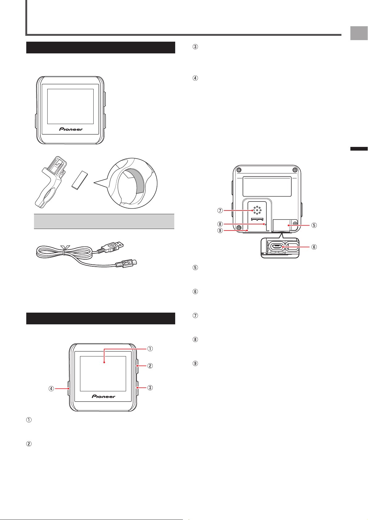
This product contains the following parts.
Main unit•
Bracket / Sheet•
Before mounting the bracket, attach the sheet to the inside •
of the clamp.
USB cable•
Strap•
Quick Start Guide•
Important Information for the User•
Warranty Card•
Part Names and Functions
Front view
■
Display (touch panel)
Touch the screen directly to select an item or change
screens.
[LAP] button
Press the [LAP] button during logging to record the lap.
Press the [LAP] button for more than 2 seconds to reset
the timer and record the log.
«
Saving Log Data (page 21)
[START/STOP] button
Press the [START/STOP] button to start or stop logging.
Press the [START/STOP] button for more than 2 seconds
to turn the power on or off.
[MENU] button
Press the [MENU] button to display the menu screen.
Press the [MENU] button on the menu screen to close
the menu screen.
Press the [MENU] button while the touch panel is locked
to unlock it.
Press and hold the [MENU] button to go back to the
previous screen.
Press the [MENU] button on the main screen of the
applications to display the home screen of the device.
Back View
■
USB connector cover
Securely close the USB connector cover when not
charging the battery or transferring data to your PC.
USB connector
Connect the USB cable to charge the device or transfer
data to your PC.
Buzzer
Provides a buzzer sound for alerts and input
confirmation.
Air pressure sensor
Do not block the sensor or the device will not operate
properly.
Bracket installation slot
Use the bracket installation slot to attach the device on
the bracket fixed to the bike.
6
EN
Getting Started
For the sake of safety, the device will not charge when •
outside the temperature range of 0 °C to 45 °C. When the
devices internal temperature is too high, full charge may not
be achieved. In this case, turn off the device, allow time to
cool down and recharge.
Connect the provided USB cable directly to a USB port of •
your PC. If the device is connected via a USB hub, it may
not charge to full capacity. Make sure that the USB output of
your PC accepts 5V/500mA.
Do not unplug the USB cable, shut down the PC or use •
sleep mode while the device is transferring data as it may
corrupt the data in the device.
4
Unplug the USB cable from the USB port.
Once data transfer is complete and the battery is fully
charged, disconnect the USB cable from the PC first,
then from the device.
5
Close the USB connector cover.
To ensure water resistant performance, firmly close the
USB cover.
Checking the Battery Level
You can check the battery level with the battery icon on the
status bar of the home screen and the menu screen.
Battery icon
When the battery is running low on power, a warning screen •
will appear “Battery Level Decreasing.” If not recharged, the
device will shut down automatically.
You can also check the remaining battery charge using the •
[System] item of "Cyclocomputer Settings".
«
System (page 45)
Operating Time Indicator
A fully charged battery allows the device to be used for the
amount of time shown below.
A fully charged battery can run for approximately 12 •
hours.
Operating time may vary depending on the operating •
conditions.
If the operating time is abnormally short, the battery may •
need to be replaced. For details, please visit our website.
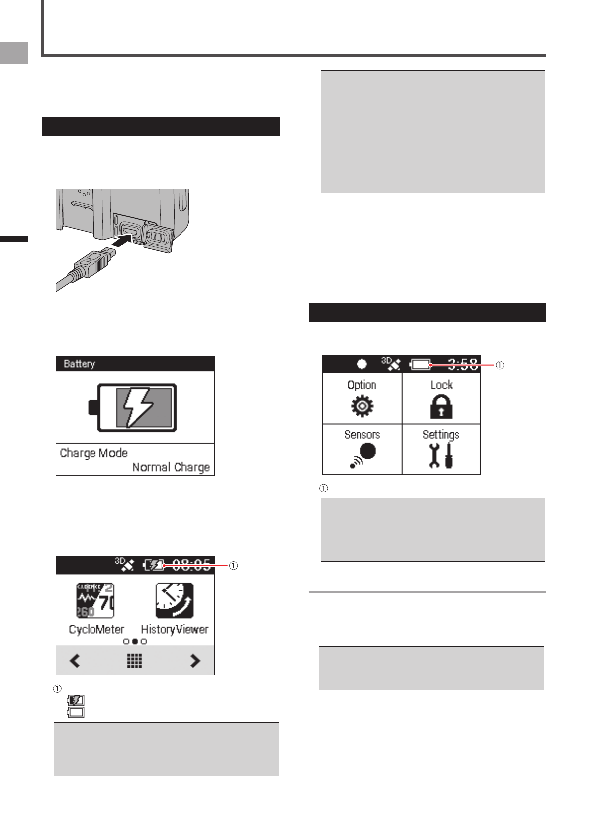
The device is not charged at the time of purchase.
Charge the device with the provided USB cable before
using it.
Charging the Device
1
Open the USB connector cover.
2
Connect the provided USB cable to the USB
connector of the device.
3
Turn your PC on and connect the USB cable to
an open USB port on your PC.
The device starts charging.
The device is turned off•
To power up•
Press the [START/STOP] button for more than 2 seconds
to turn on the device for use.
Press the [START/STOP] button for more than 2 seconds
again to turn off the device. Charging time is shorter if the
device is turned off.
Charging icon
: Charging
: Fully charged
It takes about 4 hours to charge fully (Power off or normal •
charging).
When the device is turned off, the screen turns dark after 5 •
seconds. To check the battery level, touch the touch panel
or press the [START/STOP] button.
Charging
7
EN
Getting Started
Charging
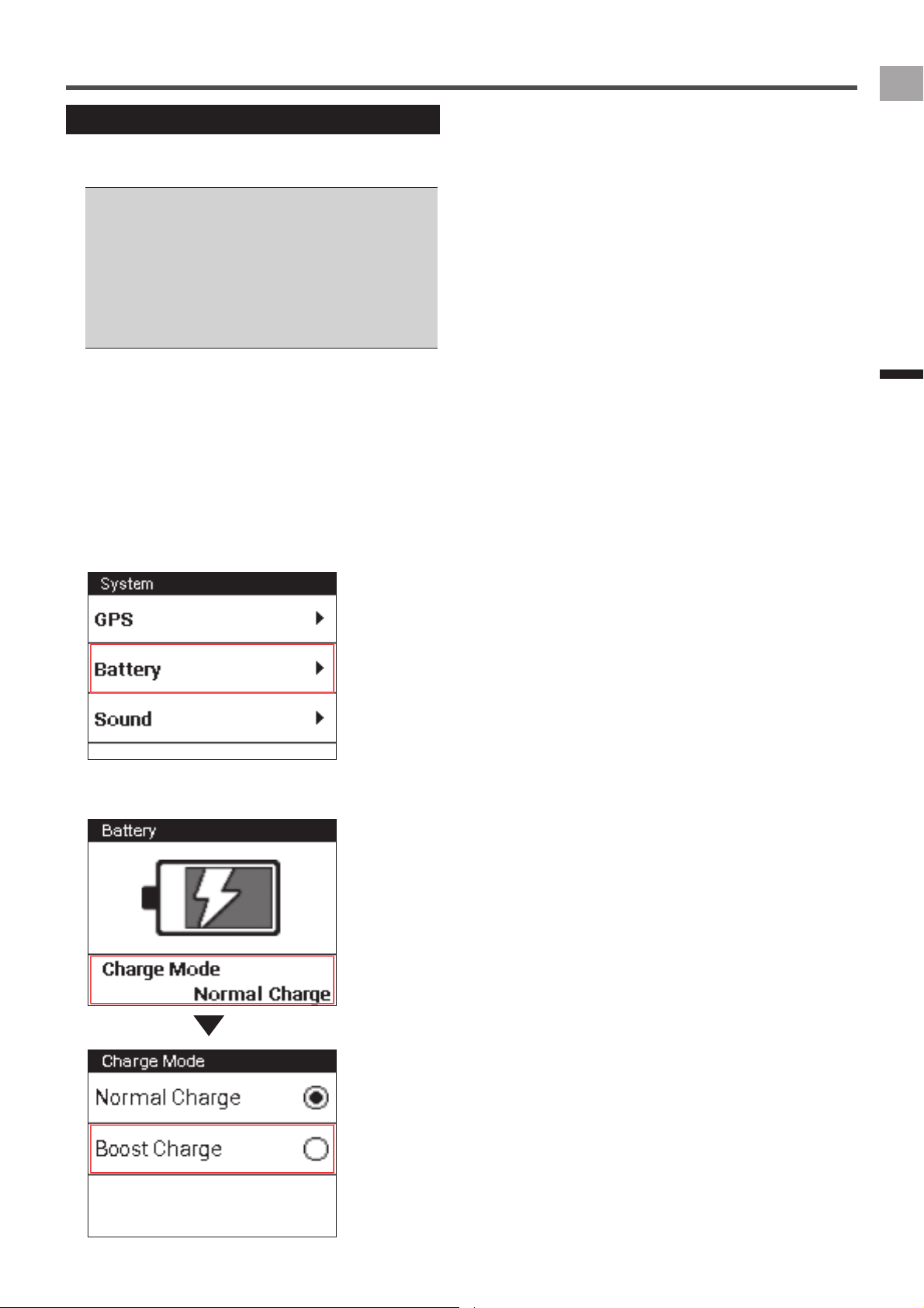
Charging Mode Setting
You can change the charging mode of the device. Using
boost charge reduces battery charging time.
You should normally use the [Normal Charge].•
Using boost charge needs output current of 1A. Make sure •
the output current you use is more than 1A.
The charging mode automatically changes to Boost Charge •
when the device detects an AC adapter which provides
output current of 1A.
Boost Charge changes to Normal Charge by disconnecting •
the device from the AC adapter. It is necessary to specify
the charging mode every time after you connect the device
to the AC adapter.
1
Connect the device to the AC adapter.
Connect the provided USB cable to an AC adapter of
which output current is more than 1A.
For information about connections, refer to “Charging the
Device” under “Charging” (
«
page 6).
2
On the home screen, tap the [Settings] icon.
This displays the settings menu.
3
Tap [System] - [Battery].
This displays the remaining battery charge and the
current charging mode setting.
4
Tap [Charge Mode] - [Boost Charge].
This sets the charging mode setting.

8
EN
Installation
Mount the Cyclocomputer on your bike.
Caution
When you mount the Cyclocomputer on your bike, be sure •
your bike is in a stable position to prevent it from falling.
Installing the Device
1
Remove the bolt from the bracket.
Remove the bolt from the bracket using a 3 mm hex
wrench.
hex wrench
Be careful not to lose the removed bolt.•
2
Mount the bracket on the handlebar of your
bike.
Be careful not to pinch your finger when mounting the •
bracket on the bike.
3
Secure the bracket with the bolt.
Apply an anti-seize compound like grease to the bolt.
Adjust the bracket horizontally from the stem, insert the
bolt into the hole and tighten lightly.
Installation on Your Bike
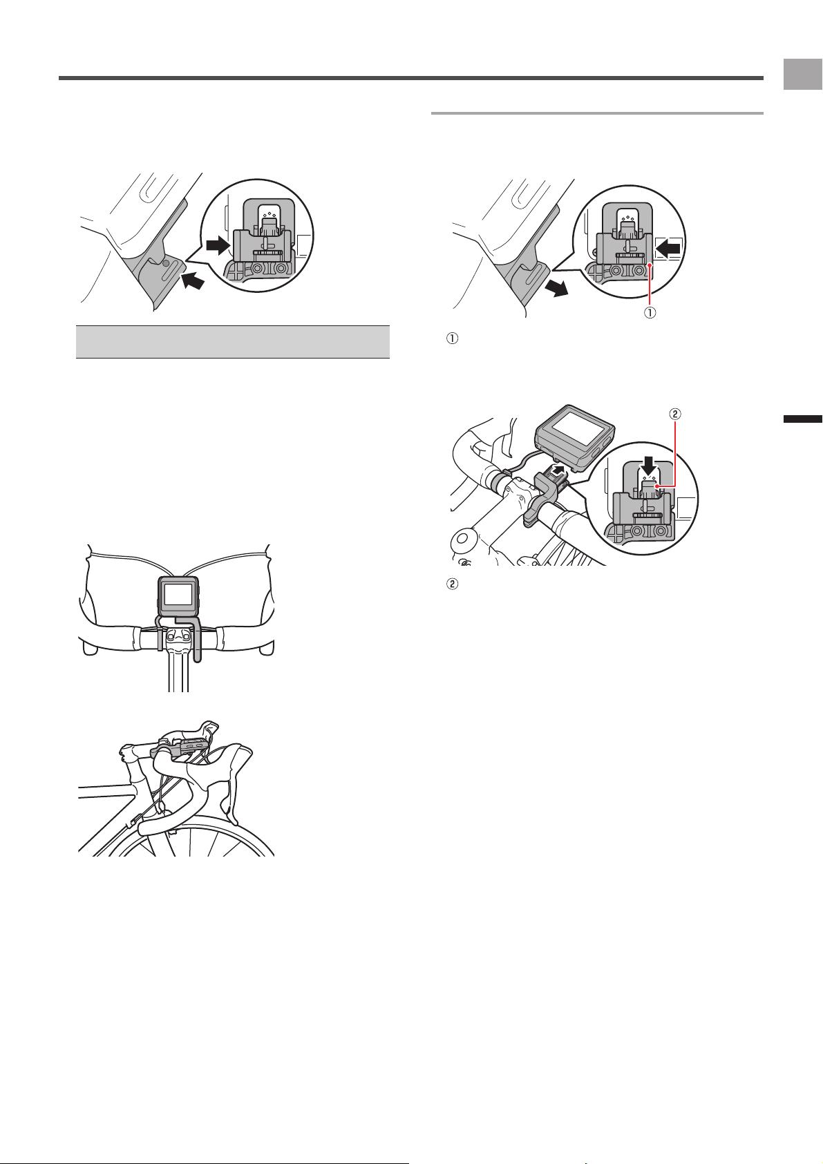
4
Check the position of the fixed lever on the
bracket.
Check the red circle on the right side of the fixed lever. If
you do not see it, the device cannot be attached.
If the red circle is hidden, push the fixed lever into the
right.
When the fixed lever is on this position,
the bracket can be mounted.
Fixed lever
5
Attach the strap to the device.
Lace the strap through the strap holes in the device.
6
Attach the device to the bracket.
Fasten the strap to the handlebars. Set the tip of the
bracket in the bracket slot on the device and push the
device until it clicks.
9
EN
Installation
Installation on Your Bike
7
Push the fixed lever into the left.
Push the fixed lever until the red circle on the right side
is hidden.
Push the fixed lever to the direction of the arrow.
Before riding with the device, make sure that the fixed lever •
red circle is hidden.
8
Adjust the angle of the device, and then tighten
the bracket.
If the device is not aligned to the center of the handlebars
or not horizontal to the stem, loosen the bolt and realign
the bracket.
After adjusting the angle, clamp the temporary joint bolt
and tighten the bracket.
Use a tool that can measure the torque to tighten the bolts.
Tightening torque: 1.2 N·m•
Front view•
Side view•
To detach the device
To detach the device from the handlebar mount, press the
fixed lever to the right, a red circle will appear next to the
device when unlocked.
Fixed lever
Pull back on the unlock lever on the bracket and lift the
device.
Unlock lever

10
EN
Installation
This device is compatible with ANT+™ sensors mounted on
your bike.
Refer to the user's manual of your ANT+ sensors for
mounting instructions.
After mounting a sensor, perform pairing with the device.
For details, refer to "Pairing Sensors" in the "Basic
Operations" chapter of this manual (
«
page 13).
This product is ANT+™ certified.
Visit http://www.thisisant.com/directory/ for a list of
compatible products and apps.
Installing Sensors
11
EN
Basic Operations
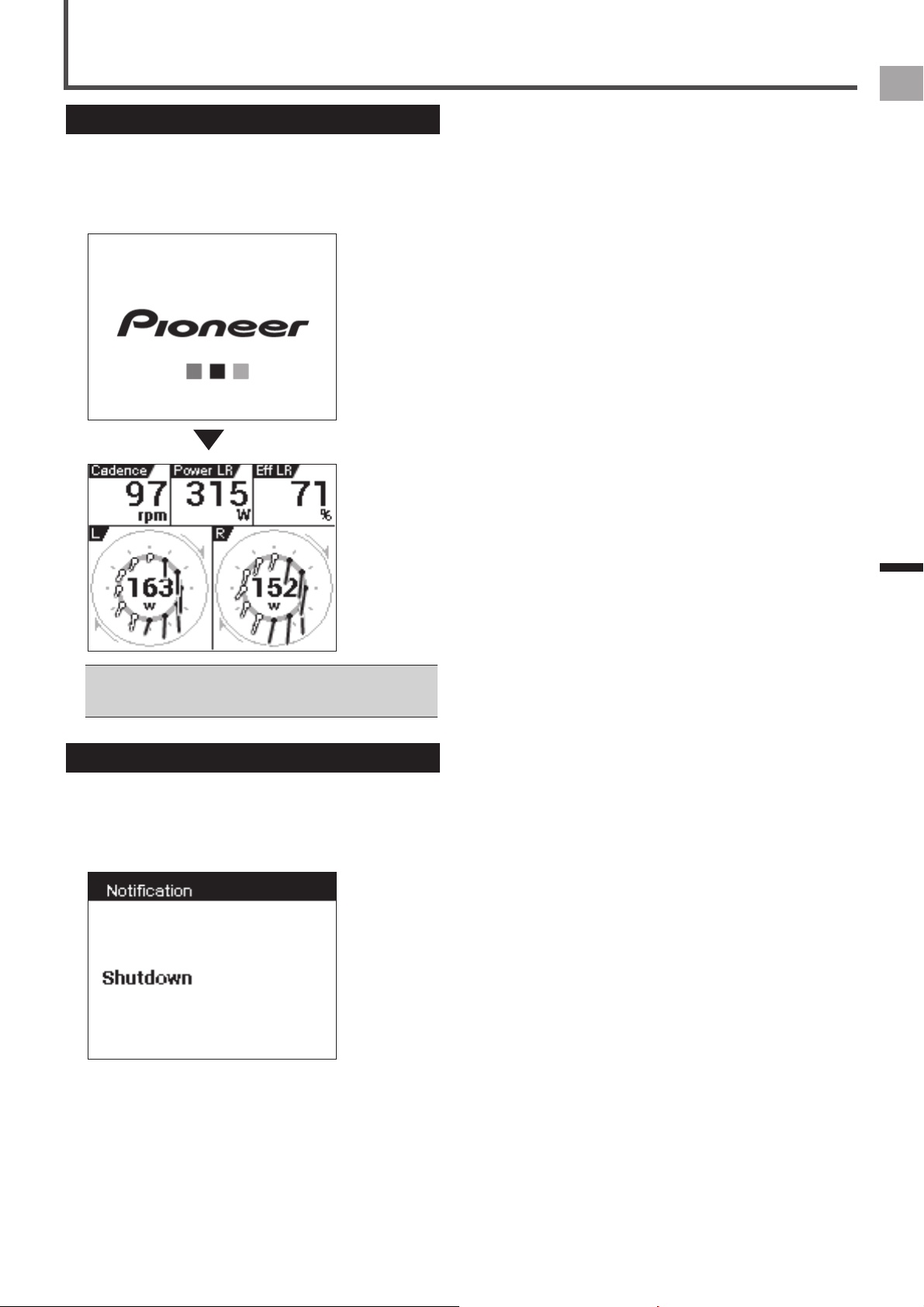
Turning Power On
1
Press the [START/STOP] button for more than 2
seconds.
An opening message will appear and the Cyclocomputer
will begin start up.
First time power up will automatically display the setup •
screen.
«
Initial Setup (page 12)
Power Down
1
Press the [START/STOP] button for more than 2
seconds.
A shutdown message will appear and the system will
power down.
Turning Power On/Off
12
EN
Basic Operations
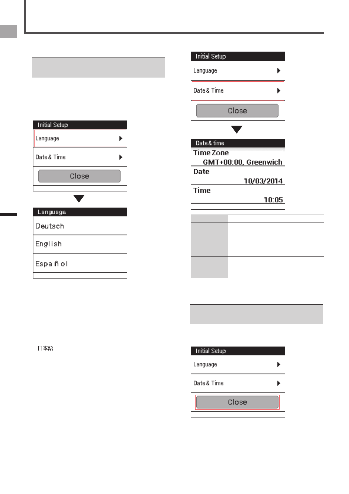
2
Tap [Date & Time] and set the date and the time.
Time Zone Select a time zone.
Date Enter the date.
Time Enter the time.
If the [24-Hour Format] check box (below) is
cleared, you can specify [AM] or [PM] for the
time setting.
24-Hour Format Check the box to display time in 24 hour
format.
Date Format Select the date format.
After all of the settings are the way you want, press and
hold the [MENU] button to return to the Initial Setup
screen.
For information about touch panel operation and text input •
methods, refer to "How to Operate the Touch Panel" (
«
page 15).
3
Tap [Close].
The Initial Setup is finished and CycloMeter starts.
When you turn the device on for the first time, the Initial
Setup screen is displayed.
You can also later change the settings you configure on the •
Initial Setup screen using "System" item of "Cyclocomputer
Settings" (
«
page 45).
1
Tap [Language] and select a language.
Drag the screen and tap the language that you want to
display.
The following steps explain the procedure when you
select [English].
Selectable languages are listed below.
The screen shots here show what is displayed when
[English] is selected as the language.
Deutsch•
English•
Español•
Français•
Italiano•
Nederlands•
•
Initial Setup
13
EN
Basic Operations
Pair the SGY-PM910H/PM900H Pedaling Monitor Sensor or
other ANT+ sensors to the device.
Before connecting the sensors
Make sure that the sensors that you want to pair are •
activated.
If more than one sensor is activated, bring the device close •
to the sensor or specify the device number to pair.
If you use the speed sensor sold separately and the wheel •
circumference is different, set the wheel circumference.
The wheel circumference is set to 2096 mm by default. For
details, refer to “Bike Edit” in “Cyclocomputer Settings” (
«
page 49).
1
Mount the sensors on your bike.
For details about how to mount sensors, refer to the
user’s manual of your sensors.
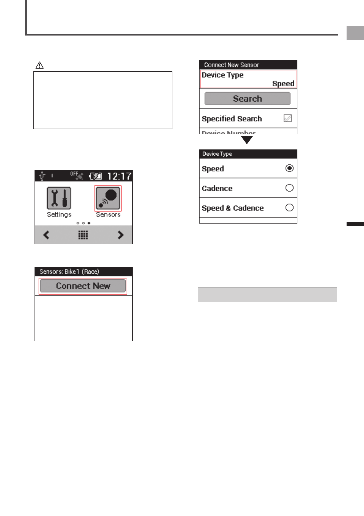
2
On the home screen, tap the [Sensors] icon.
3
Tap [Connect New].
This displays the sensor settings menu.
Pairing Sensors
4
Tap [Device Type] and then select the type of
sensor(s) you wish to pair.
Types of compatible sensors:
SpeedSensor•
CadenceSensor•
Speed & Cadence Sensor•
Heart Rate Monitor•
PowerMeter•
Pedaling Monitor L•
Pedaling Monitor R•
If multiple sensors are activated, specify the device number.•
«
Specifying the device number (page 14)

14
EN
Basic Operations
Pairing Sensors
5
Tap [Search].
The message “Searching Please wait.” appears. If the
sensors are paired, the information from the sensors is
displayed.
6
Confirm the information from the sensors.
Confirm that “OK” is displayed in the [Error Rate] area.
If “Processing...” is displayed in the [Error Rate] area, •
the sensor information is not received properly due to a
communication error. Make sure that the sensor is activated,
bring the device closer to the sensor and try pairing again.
You may not pair with the sensor due to the influence of the •
2.4 GHz frequency band. If “Processing...” is displayed even
if the device is moved closer to the sensor and paired with
it, try again someplace where there is no interference from
microwaves, radio waves, or wireless equipment.
Specifying the device number
If you specify the sensor device number, follow the
procedures listed below before pairing the sensor.
1
Check the [Specified Search] check box in the
sensor connection menu.
Refer to the user’s manual of the ANT+ sensor for •
information about how to look up the device number.
2
Tap [Device Number].
3
Input the device number and tap .
If you specify the device number, make sure that the •
specified number is displayed in [Device Number] of the
sensor information confirmation screen.
15
EN
Basic Operations
The display of this device is a touch panel for direct
operation.
Tap
■
Quickly touch an item on the screen to select or confirm it.
Swipe
■
Move your finger in a vertical or horizontal direction on the
screen.
Do this to switch screens or scroll.
Long touch
■
Touch and hold an item on the screen.
Do this to open the pop-up menus.
How to Operate the Touch Panel
Drag
■
To move an item on the screen, simply touch the item with
your finger and move it to the new location.
Precautions when using the touch panel
Do not use a hard or sharp object to operate the touch •
panel, doing so may damage it.
Do not use commercially available protective sheets or •
films as they may interfere with normal operation. They may
cause the device to not operate correctly.
You can operate the touch panel while wearing gloves. •
Apply slightly more pressure than with common touch
panels.
16
EN
Basic Operations
How to Operate the Touch Panel
Operations List
Scrolling a List
Dragging a list scrolls it.
Swiping a list scrolls it in the swipe direction at high speed. •
Tapping the screen while a swiped list is scrolling at high
speed stops the scrolling.
Selecting and Clearing a Check Box
Tapping a check box toggles it between being selected and
cleared.
A check box is selected when it has a check mark inside it.
Selected Check Boxes•
Cleared Check Boxes•
Inputting Text
An input screen will appear when text or numeric input is
required.
10-key Pad Input
A 10-key pad is displayed on the input screen for
alphanumeric characters and symbols.
Tap the keys for the characters you want to input.
Text and symbol input•
Numeric input•
(Text input only):
Toggles between upper-case and lower-case text input.
:
Tap to backspace and delete the character to the left of
the cursor. Long touch to continually delete characters.
:
Switches between text input and numeric input.
:
Tap to input a one-character space.
:
Finalizes text input.

17
EN
Basic Operations
How to Operate the Touch Panel
Inputting Alphanumeric characters and
■
symbols
When inputting an alphanumeric character or a symbol, tap
the same key several times until the character or symbol you
want to input is displayed.
For example, if you want to input “bike”, tap the keys as
follows.
[abc] key:2 times → [ghi] key:3 times → [jkl] key:2 times
→ [def] key:2 times
If you do not input any other character after tapping a
key and selecting a character to input, the underline is
cleared and the selected character is entered. To input the
characters on the same key consecutively, such as “aba”,
wait a while for the first character to be entered, and then
select the second character.
Dialog Box Input
An input dialog box will appear when you need to select a
numeric value from a preset range.
Tap the value you want to change and then use [+] and [-] to
change it.
When the value is the way you want, tap [OK].
Currently selected value
To exit the dialog box without saving the input content, tap •
[Cancel].
18
EN
Basic Operations
Home screen
Viewing the Home Screen and
Performing Home Screen Operations
The home screen can be used to start up various device
applications.
Pressing and holding the [MENU] button while an application
main screen is displayed displays the home screen.
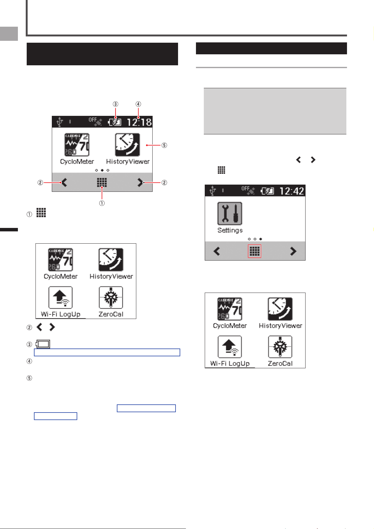
(Launcher button)
Tap to display all applications currently installed on the
device (Launcher screen).Swipe the screen right or left
to change the pages.
/
Tap to change pages.
(Remaining battery charge icon)
Shows the remaining battery charge and charging status.
Current time
Displays the current time.
Page
Displays application shortcut icons. Tapping an icon
starts up the corresponding application.
Swipe the screen right or left to change pages.
There are a total of three pages. Each page is assigned
up to two icons.
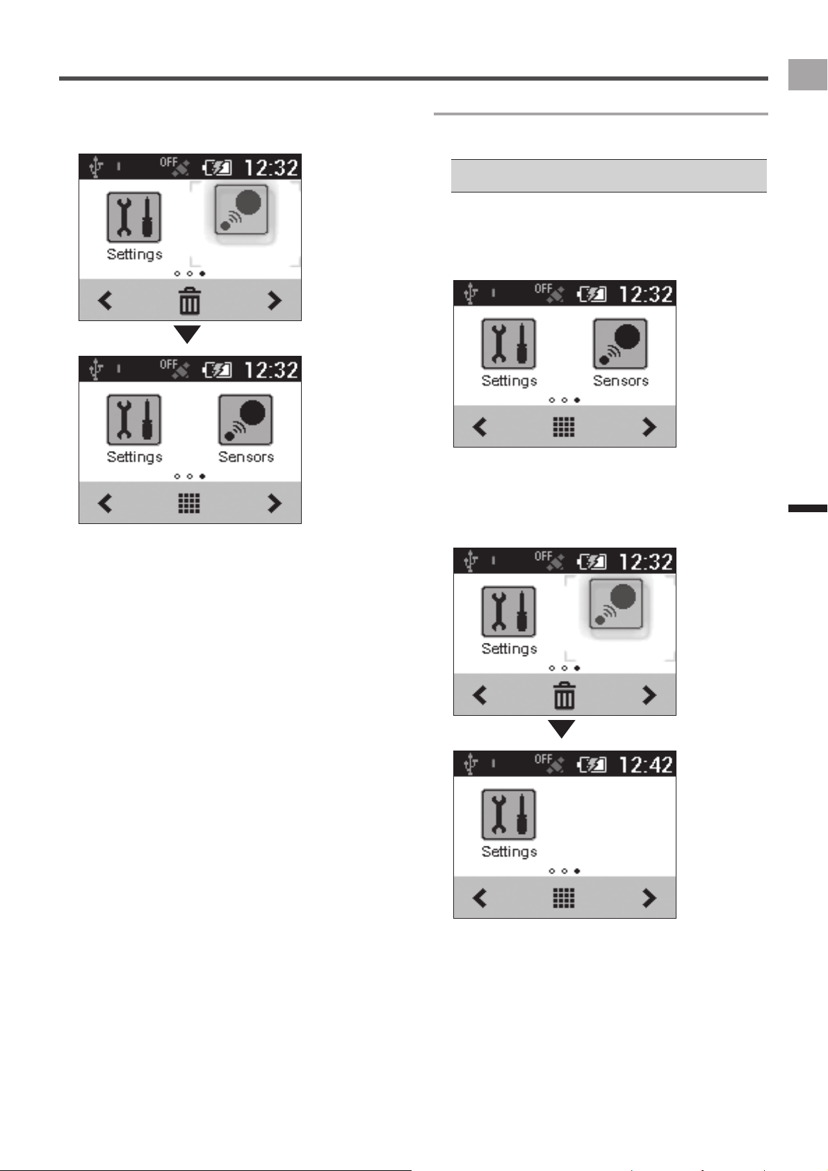
Customizing the Home Screen
Arranging Home Screen Shortcut Icons
Use the procedure below to arrange application shortcut
icons on the home screen.
Up to two shortcut icons can be assigned to each home •
screen page. If you want to assign a shortcut icon to a page
that already has two icons assigned to it, delete one of the
currently assigned icons.
Deleting a shortcut icon from the home screen does not
delete the application itself.
«
Deleting a Shortcut Icon from the Home Screen (page 19)
1
Display the page whose shortcut icons you
want to arrange.
Swipe the screen right or left, or tap or .
2
Tap (Launcher button).
This displays the Launcher screen.
3
Long touch the application icon you want to
move.
This zooms the icon and displays the home screen.
19
EN
Basic Operations
Home screen
4
Drag the shortcut icon to the location you wish
to move it and release your finger.
This moves the shortcut icon to the new location.
Deleting a Shortcut Icon from the Home Screen
Use the procedure below to delete a shortcut icon from the
home screen.
Deleting a shortcut icon from a page does not delete the •
application itself.
1
Long touch the application icon you want to
delete.
This zooms the icon and displays a trash can at the
bottom of the screen.
2
Drag the shortcut icon to the trash can and
then release your finger.
Remove your finger after the shortcut icon color
changes.
This deletes the shortcut icon from the home screen.
20
EN
Workout
Basic Workout Flow
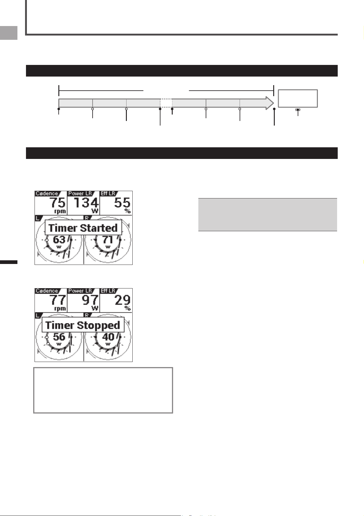
This device is designed to log a variety of sensor data as well as GPS location data during your workout. In this device, the
beginning of the training to the end of the training is called “ workout”.
Basic Flow of the Workout
[Start]
Lap1 Lap2
Lap3 Lap3 Lap4
Lap5
[Lap]
[Lap]
[Stop]
[Start]
[Lap]
[Lap]
[Stop]
[Lap]
(2 sec.)
Workout
Timer
Resetting
1
Press the [START/STOP] button to start
logging.
[Timer Started] is displayed.
2
Press the [START/STOP] button to stop logging.
[Timer Stopped] is displayed.
You can start and stop logging at any time while the device •
is turned on except while the device is connected to a PC or
during setting initialization.
A logging operation can continue for up to 360,000 points.•
If the [LAP] button is pressed during logging, a lap is •
recorded. Up to 300 laps can be recorded during a single
logging operation.
Logging Interval
■
Under initial factory default settings, the device is configured
to save various types of data at 1 second intervals when
logging.
You can change settings so the logging interval is to be •
adjusted in accordance with bike riding speed.
The logging interval becomes shorter as bike riding speed
increases and longer as riding speed decreases.
«
Logging (page 45)
Logging Start/Stop
21
EN
Workout
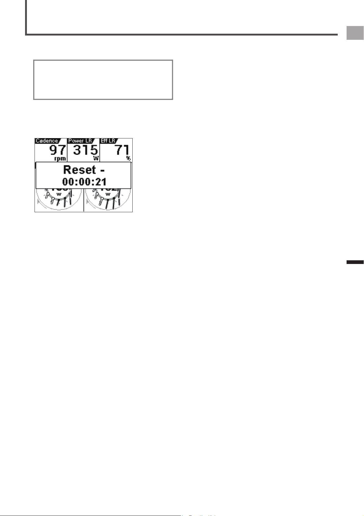
Saving Log Data
After you have completed your ride, reset the timer to save
the log data to the built-in flash memory of the device.
Log data is not saved to the built-in flash memory until the •
timer is reset. Be sure to reset the timer to save the log data
you need.
Reset the timer after the logging operation is complete. The •
timer cannot be reset while logging is in progress or the
device is connected to a PC via the USB connection.
1
Press and hold the [LAP] button for more than
2 second.
The log data is saved, and the timer is reset.
The log data is saved in the device “\Pioneer\Log” folder.
22
EN
Workout
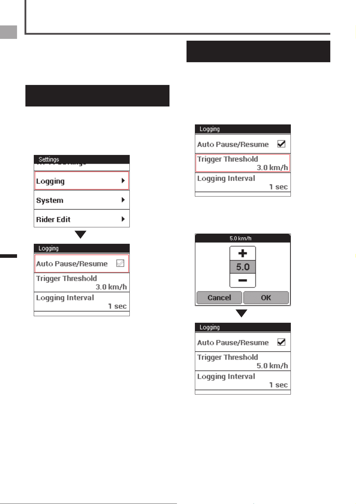
Auto Pause/Resume Settings
The Auto Pause/Resume function automatically pauses and
resumes logging whenever a preset speed is attained while
logging is in progress.
You can configure speed and condition settings as needed
for Auto Pause/Resume.
Enabling and Disabling Auto
Pause/Resume
1
On the home screen, tap the [Settings] icon.
This displays the settings menu.
2
Tap [Logging] and then touch [Auto Pause/
Resume].
This enables Auto Pause/Resume.
Configuring Auto Pause/Resume
Conditions
Auto Pause/Resume conditions specify the speed at which
logging will be automatically paused and resumed.
1
On the home screen, tap the [Settings] icon.
This displays the settings menu.
2
Tap [Logging] - [Trigger Threshold].
This displays the Auto Pause/Resume condition setting
screen.
3
Input the speed and then tap [OK].
For example, input 5 to have logging stop temporarily
whenever speed drops to 5 km/h or lower and resume
when it rises above 5 km/h.
23
EN
Workout
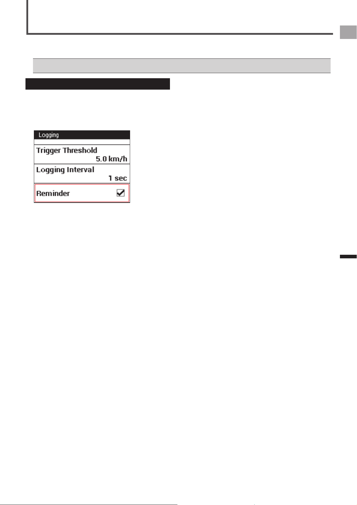
The Reminder function displays a message when you start riding without logging.
When the Reminder function is set to on, the message is displayed every minute that you keep riding without logging.
The Reminder function determines you are riding by one of the values of speed, cadence, or power. It may not operate depending on •
the GPS Speed setting, or the conditions of the sensor connection or GPS reception.
Reminder Settings
Enabling and Disabling Reminder
1
On the home screen, tap the [Settings] icon.
This displays the settings menu.
2
Tap [Logging] and then touch [Reminder].
This enables Reminder.

24
EN
Workout
The Auto Lap function automatically records a lap without the [LAP] button needing to be pressed, whenever a preset time,
distance, or point is attained.
Auto Lap Settings
Enabling and disabling Auto Lap
1
On the home screen, tap the [Settings] icon.
This displays the settings menu.
2
Tap [Logging] and then touch [Auto Lap].
This enables Auto Lap.
The Auto Lap function operates only while logging is in progress. It does not operate if logging is stopped or in auto pause.•
Configuring Auto Lap Conditions
Use the procedure below to specify the conditions (trigger) by which the Auto Lap function records a lap.
1
On the home screen, tap the [Settings] icon.
This displays the settings menu.
2
Tap [Logging] – [Auto Lap].
This displays the Auto Lap settings screen.
3
Tap [Auto Lap Trigger] and select a trigger to record a lap.
You can select [Location], [Distance], or [Time] as a trigger.
25
EN
Workout
Auto Lap Settings
4
Configure the detailed trigger settings.
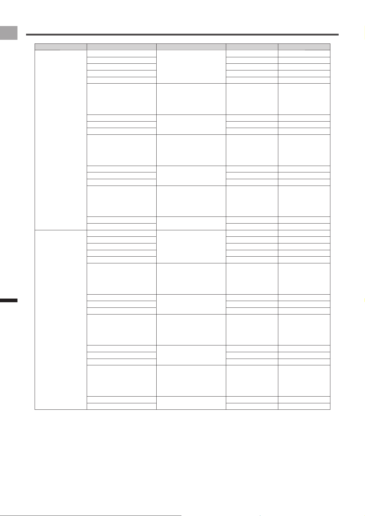
The setting items below can be specified according to the selected trigger.
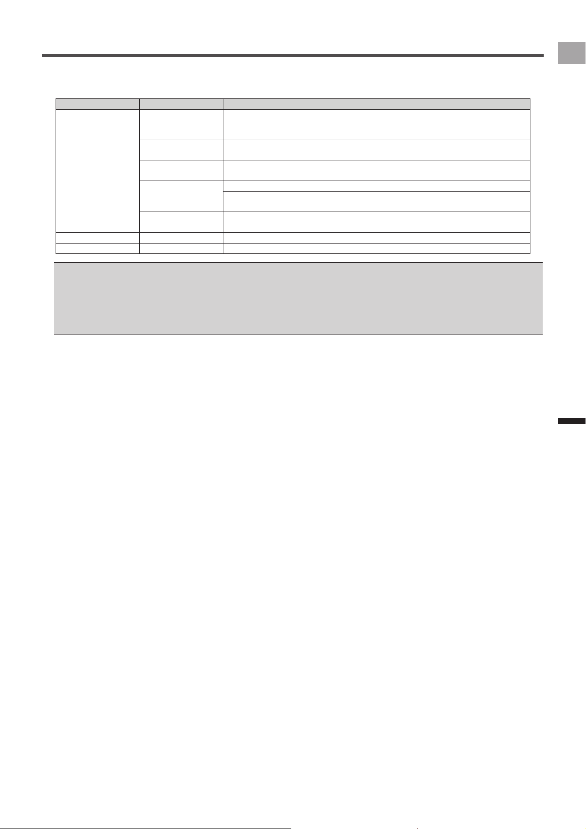
Trigger Setting Item Description
Location Lap Location Registers a point as an auto lap location where the [LAP] button is pressed while
logging is in progress, and from the next time when passing nearby the auto lap
location, records a lap automatically.
Start Location Registers a point as an auto lap location where logging starts, and from the next time
when passing nearby the auto lap location, records a lap automatically.
User Registration
Location
Records a lap at the auto lap location registered with the [User Location Registration]
button.
Trigger Area Size Specify the distance from the auto lap location in which the system records a lap.
For example, set [50 m] to record a lap when approaching to within a 50 m radius of the
location.
User Location
Registration
Press to register an actual point as an auto lap location.
Distance Lap Distance Records a lap when a preset lap distance is attained.
Time Lap Interval Records a lap when a preset lap time is attained.
You can register up to 10 auto lap locations by using the [START/STOP] or [LAP] button.•
You can register only 1 location by using the [User Location Registration].•
The auto lap locations will be cleared when the timer is reset.•
You can record a lap manually by pressing the [LAP] button even while the Auto Lap function is set to on. If [Lap Location] is set as an •
auto lap trigger, an auto lap location is registered as well as a lap being recorded.
If GPS is not being received, the registration of auto lap locations by using the [START/STOP] or [LAP] button, or user locations by using •
the [User Location Registration] are not available.
26
EN
Workout
Transferring the Data
Backing up Log Data to a PC
You can transfer the log data in the built-in flash memory of
the device to your PC.
Transferred data can be analyzed using the Pioneer™
Cyclo-Sphere web service.
1
Connect the device to your PC with the
provided USB cable.
The PC will recognize the device as a mass storage
device.
For information about connecting the device to a PC, refer •
to "Charging the Device" under "Charging" (
«
page 6).
2
Select the data you want to transfer, and then
save it anywhere on the PC.
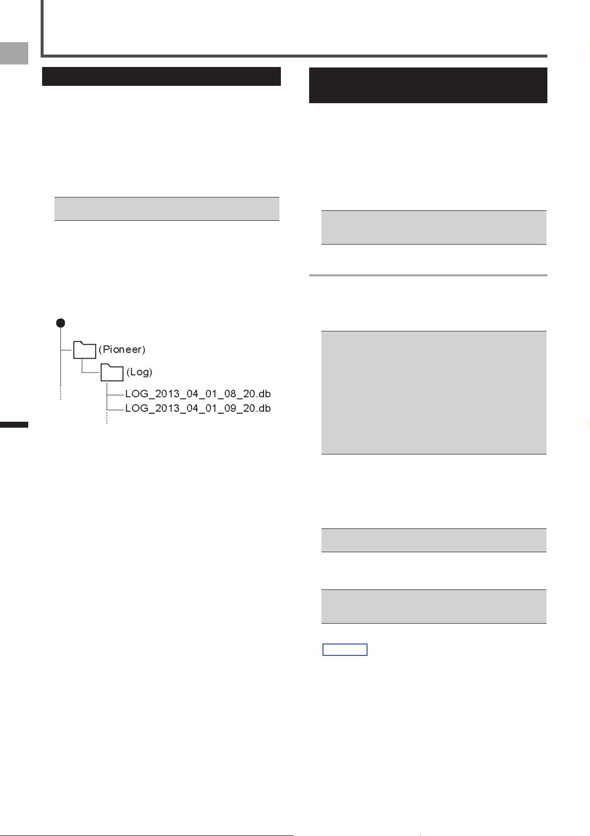
The log data is saved in the “\Pioneer\ Log” folder.
Save it anywhere on the PC.
The file name is the date and hour that the training log
started.
(Example: LOG_2013_04_01_08_20.db)
Log Data Upload to the Analysis
Service
The log data in the device can be uploaded to the Cyclo-
Sphere analysis website in the following two ways.
Uploading the data via “Pioneer Cycle Cloud Connect” by •
connecting the device to a PC.
«
Uploading Log Data with a PC (page 26)
Uploading the data via Wi-Fi by using the application on •
the device.
«
Wi-Fi LogUp (page 40)
The device’s Wi-Fi settings must be done to upload the log •
data via Wi-Fi.
«
Wi-Fi Settings (page 44)
Uploading Log Data with a PC
If “Pioneer Cycle Cloud Connect” application is installed on
your PC, the log data in the device’s built-in flash memory
will be automatically uploaded to the Cyclo-Sphere analysis
website.
Refer to the support page for instructions on how to install •
“Pioneer Cycle Cloud Connect” application to your PC.
[For American Users]
http://www.pioneerelectronics.com
[For Canadian Users (ENGLISH)]
http://www.pioneerelectronics.ca/POCEN/Support
[For Canadian Users (FRENCH)]
http://www.pioneerelectronics.ca/POCFR/Soutien
[For European Users]
http://www.pioneer.eu/eur/support/page.html
Your PC will need Internet connection to upload your data to •
Cyclo-Sphere.
1
Connect the device to your PC with the USB
cable that came with the device.
If the automatic upload of ride log data is set on “Pioneer
Cycle Cloud Connect”, Cyclo-Sphere login ID and
password input screens are displayed.
Refer to the “Charging the Device” under “Charging” •
(
«
page 6) for connecting the device to a PC.
2
Input the login ID and password.
The log data upload is started automatically.
New log data not previously uploaded to Cyclo-Sphere will •
be uploaded.
Do not disconnect the device and the PC during upload.•
3
Disconnect your device from your PC after the
upload is completed.
27
EN
Application
CycloMeter
CycloMeter is the main application on this device. It provides
the trip data of your bike ride. When the device is turned on,
CycloMeter is activated first.
To activate CycloMeter from the home screen, tap the
CycloMeter icon.
Viewing Pages and Performing
Page Operations
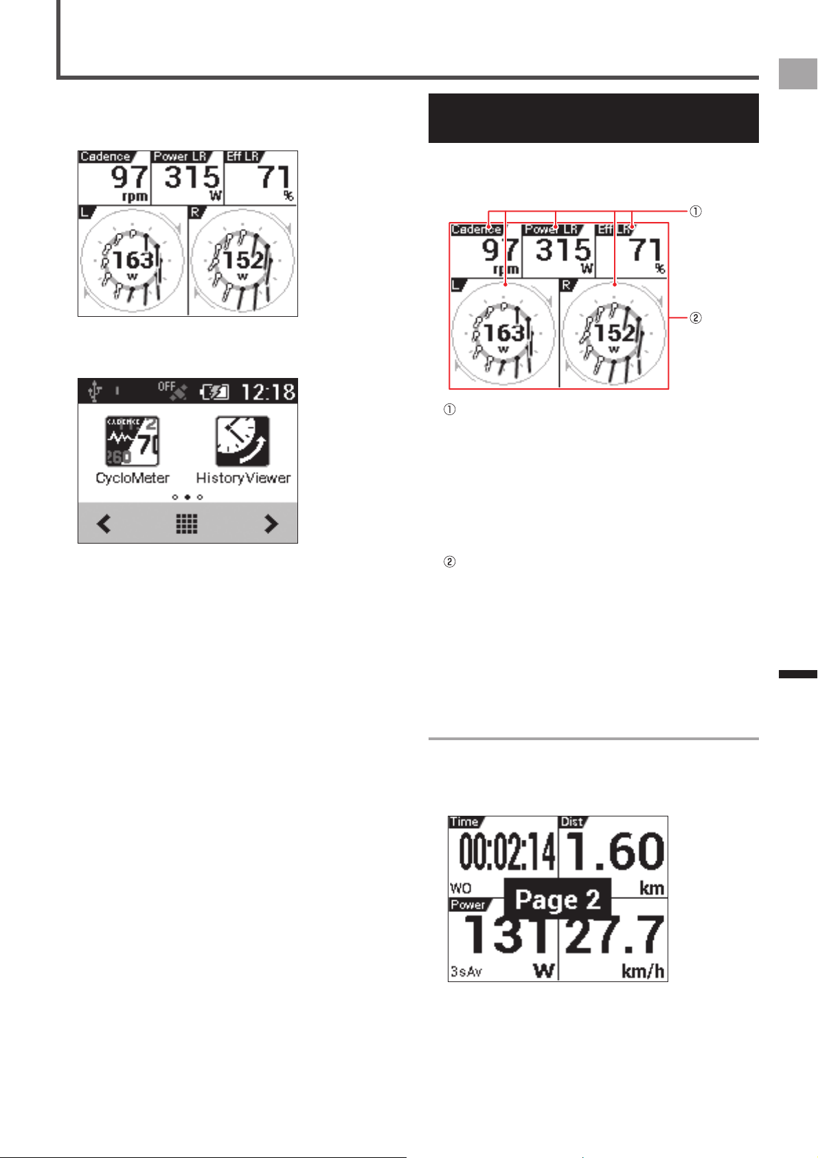
The CycloMeter screen consists of pages and data fields.
A variety of information is displayed as a data field on the
page.
Data Fields
Data fields show name, type, unit and other
information.
Long touching a data field for one second or more will
display an editing screen.
«
Data Fields Settings (page 33)
Refer to the “Data Field Type /Pattern List” (
«
page
34) for the contents that can be displayed on the data
field list.
Page
A screen that displays the data field layout.
The number of data fields or layout that is displayed
for each page is controlled as “Pageset”. You can
change the Pageset according to your individual
needs or edit the number of data fields and the layout
displayed for each page.
«
Changing the Pageset (page 30)
«
Pageset Edit (page 32)
Changing Pages
Swipe the page right or left to change the page; the page
number is displayed in the middle of the screen.
For information about pages that can be changed under
default settings, refer to "Pageset List" (
«
page 31).
28
EN
Application
CycloMeter
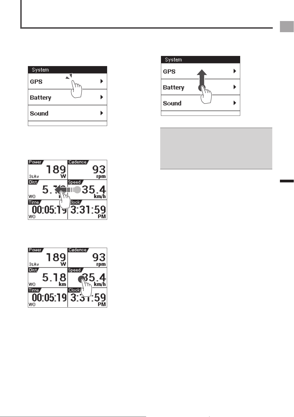
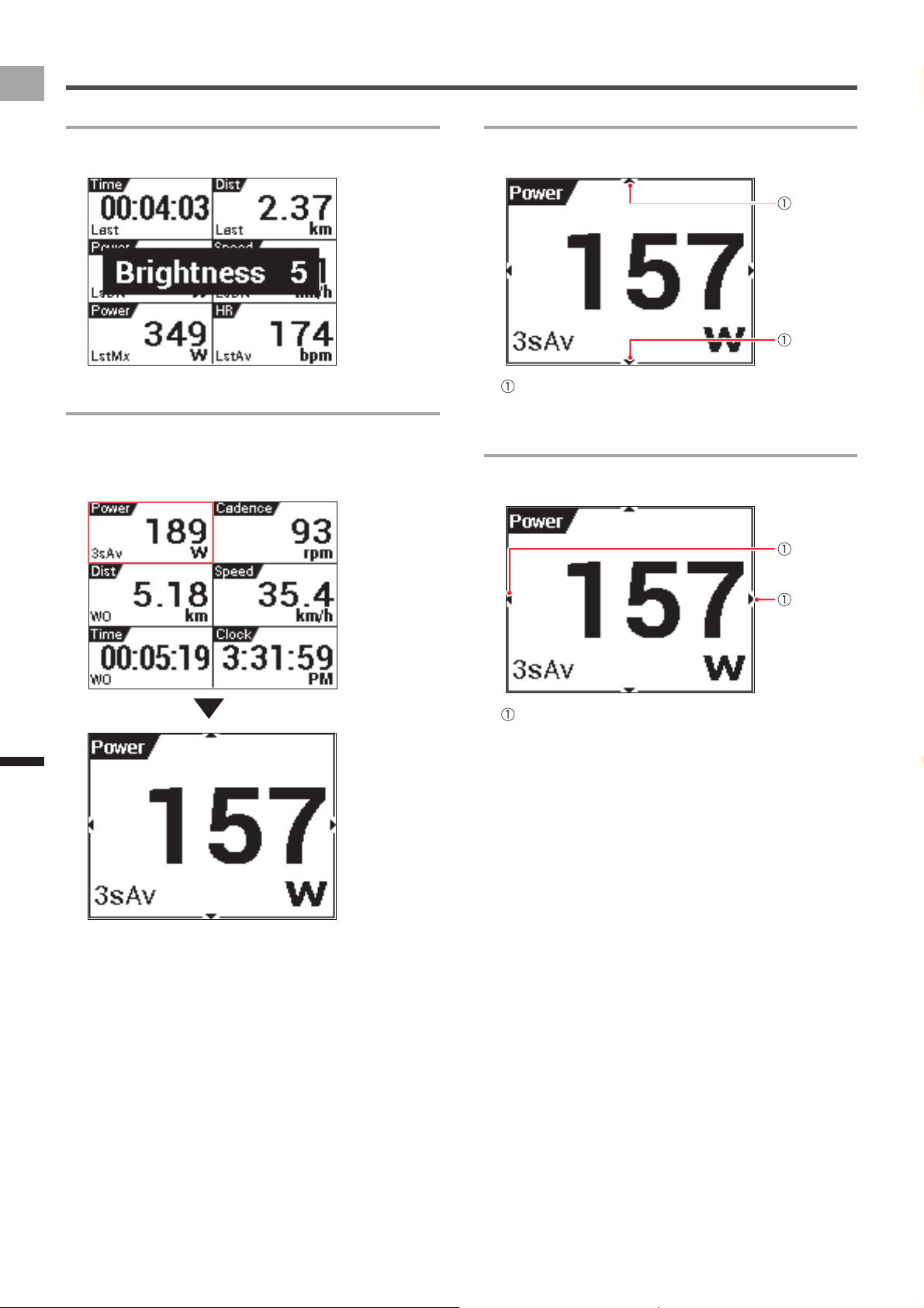
Changing Screen Brightness
Swipe the screen upwards or downwards to adjust screen
brightness to one of ten levels (1 to 10).
Zooming Data Fields
Tap the Data Field to zoom in. Tap the Data Field again to
return to the page display.
Press and hold the [MENU] button to return to the page
display.
Changing the Data Type of a Data Field
You can change the data type by swiping upwards or
downwards while a data field is zoomed.
Data type change mark
Indicates that the data type can be changed.
Changing the Display Type of a Data Field
You can change the display type by swiping left or right while
a data field is zoomed.
Display type change mark
Indicates that the display type can be changed.
29
EN
Application
Transferring the Data
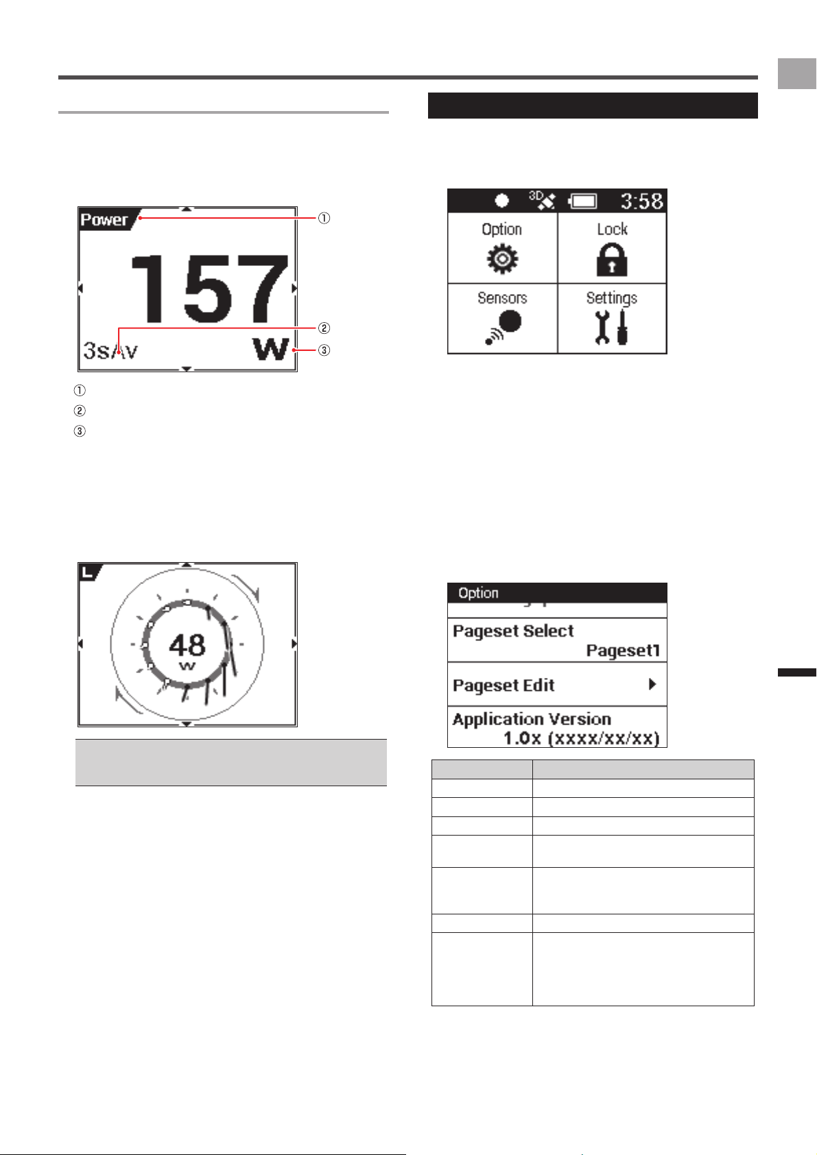
Data Field Types
A data field can be a "numerical" type or a "graph" type.
Numerical type
■
A value type displays information obtained from a sensor as
numeric values.
Label
Sub-label
Unit
Graph type
■
A graph type displays information obtained from a sensor as
a graph.
Pedaling Chart•
Shows the pedaling force value or direction (vector).
Current power (W) is displayed in the center of the graph.
To display Pedaling Chart, you need to connect the device •
with the pedaling monitor sensor SGY-PM910H/PM900H
series.
Option Settings
Option settings are CycloMeter settings.
1
Press the [MENU] button.
This displays the Main menu.
[Lock]:
Tap to lock the screen.
Press the [MENU] button to unlock.
[Sensors]:
Tap to configure settings for the currently selected bike
sensor.
«
Sensor Settings (page 50)
[Settings]:
Tap to configure general device settings.
«
Cyclocomputer Settings (page 43)
2
Tap [Option].
Option menu is displayed. Tap the setting items.
Setting Item Description
ZeroCal Activates ZeroCal.
HistoryViewer Activates HistoryViewer.
Wi-Fi LogUp Activates Wi-Fi LogUp.
Pageset Select Select to configure Pageset settings.
«
Changing the Pageset (page 30)
Pageset Edit Select to edit the display contents of each
page.
«
Pageset Edit (page 32)
Application Version Displays CycloMeter version information.
Exit CycloMeter Exits CycloMeter and displays the home
screen.
Pressing and holding the [MENU] button
while the CycloMeter screen is displayed
also exits CycloMeter.
30
EN
Application
Transferring the Data
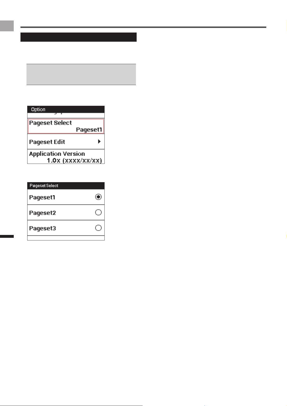
Changing the Pageset
Use the procedure below to change the Pageset displayed
by CycloMeter.
You can choose from among five Pageset settings.
You can also edit the contents of each Pageset.•
«
Pageset Edit (page 32)
For information about factory default Pagesets, refer to •
"Pageset List" (
«
page 31).
1
Press the [MENU] button.
2
Tap [Option] - [Pageset Select].
3
Tap the Pageset you want to change.
This changes the Pageset menu.
31
EN
Application
Transferring the Data
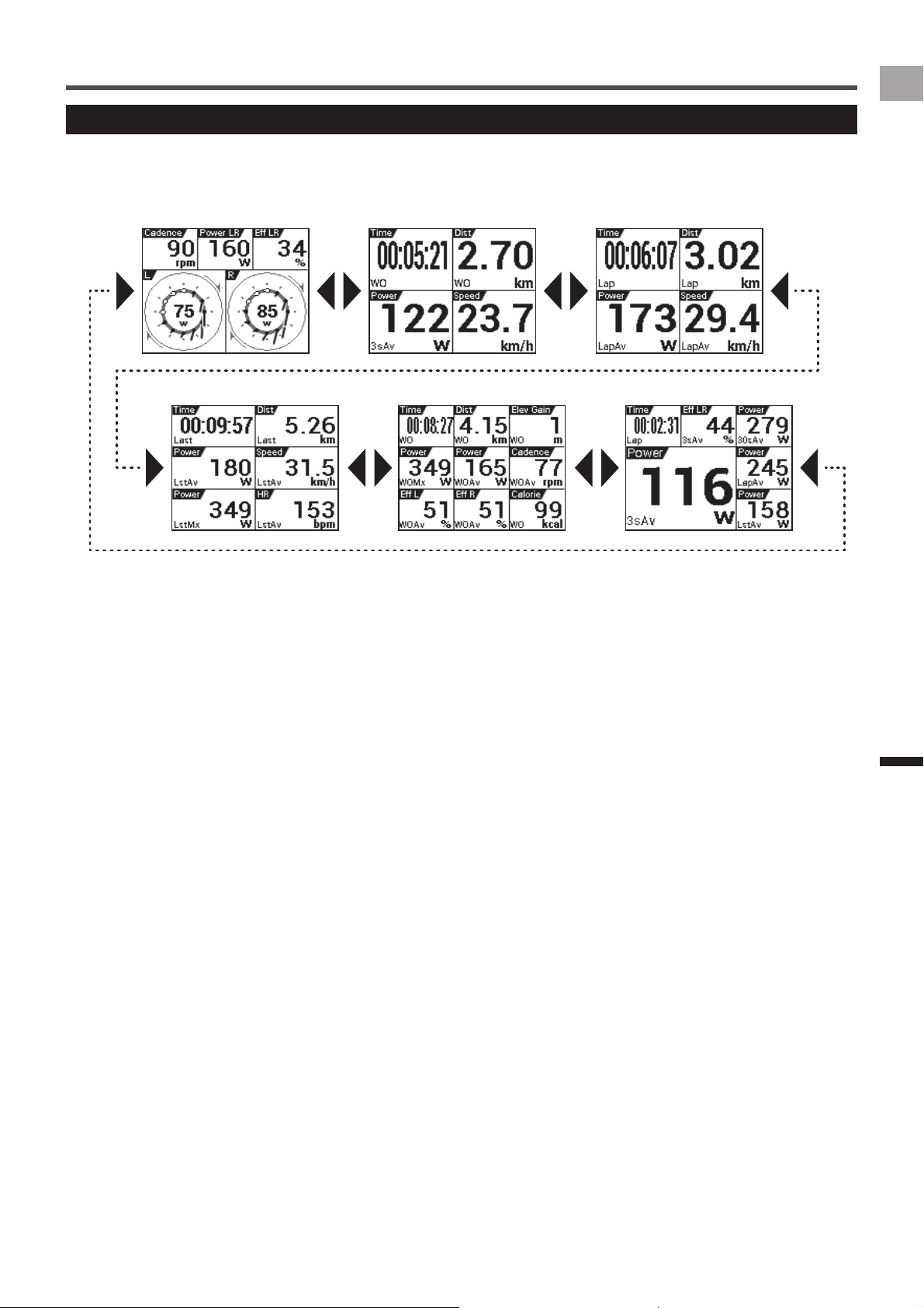
Pageset List
The following shows the contents of the factory default Pageset 1.
Pageset 1
■
Page 1 Page 2 Page 3
Page 4 Page 5 Page 6
32
EN
Application
Transferring the Data
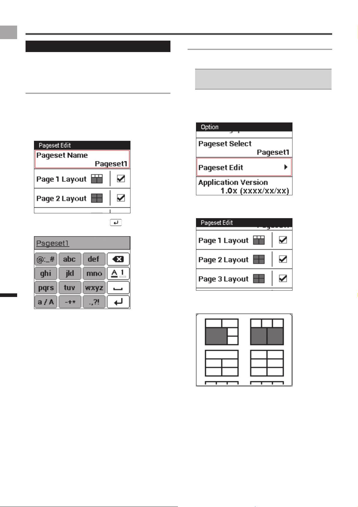
Pageset Edit
You can use the procedures in this section to edit the
contents of the Pageset you select with "Pageset Select".
«
Option Settings (page 29)
Renaming a Pageset
Use the procedure below to edit the name of the currently
selected Pageset.
A Pageset name can be up to 20 characters long.
1
Press the [MENU] button.
2
Tap [Option] - [Pageset Edit] - [Pageset Name].
3
Input a name and then tap .
This changes the Pageset name.
Changing the Page Layout
Use the procedure below to change the number of data
fields and the layout displayed for each page.
The data field types and the number of data fields that can •
be displayed depend on the page layout.
«
Layout Pattern List (page 33)
1
Press the [MENU] button.
2
Tap [Option] - [Pageset Edit].
This displays the pageset menu.
3
Tap the page you want to change.
This displays the layout list.
4
Tap the layout you want to select.
This changes the page to the selected layout.
33
EN
Application
Transferring the Data
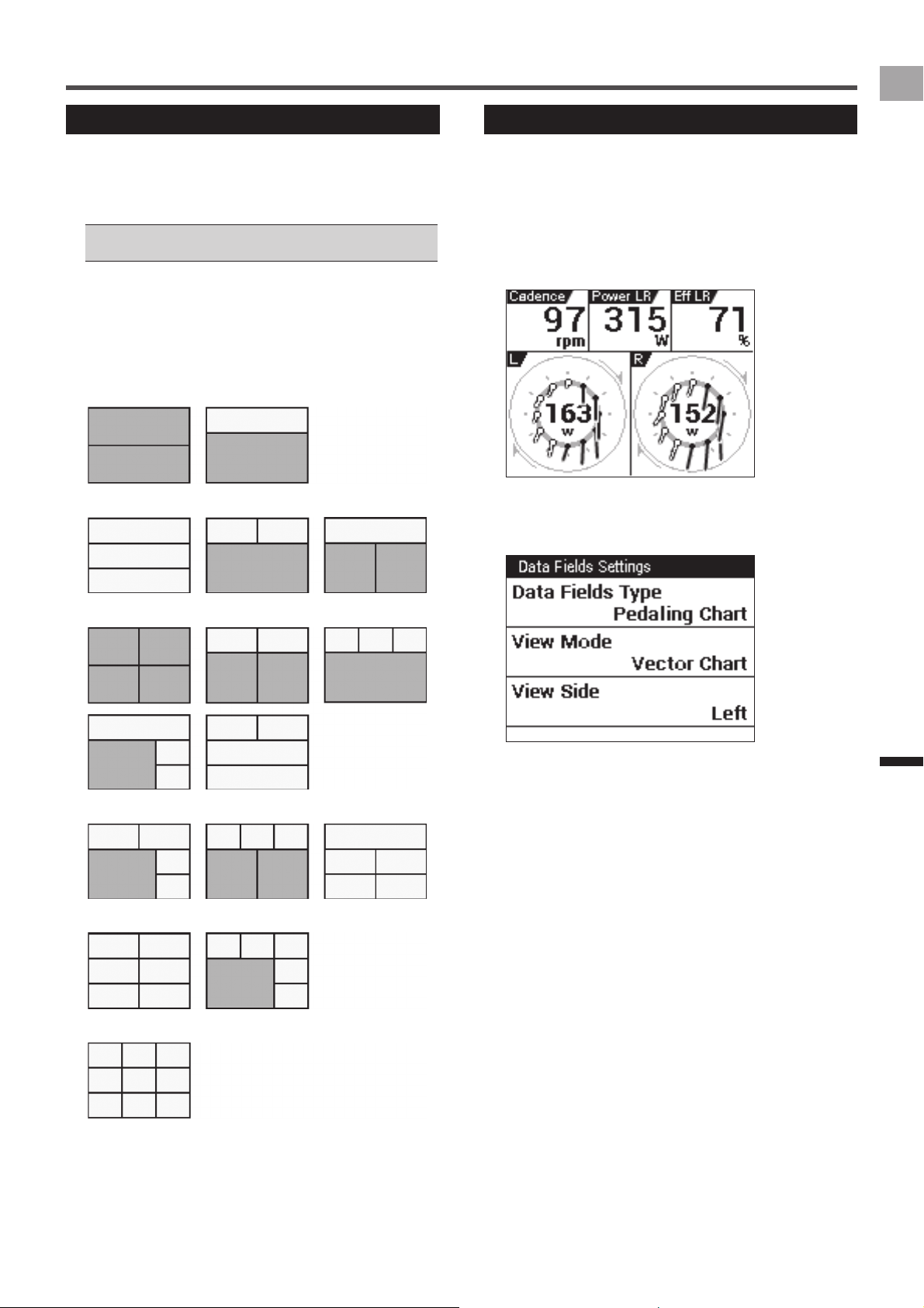
Layout Pattern List
The device has 16 patterns that can be used as page
layouts.
The data field types and the number of data fields that can
be displayed depend on the page layout pattern.
For information about data field types, refer to "Data Field •
Type/Pattern List" (
«
page 34).
Layout Pattern Data Fields
■
Gray data fields: Can be configured as numerical type and
graph type data fields.
White data fields: Can be configured as numerical type data
fields only.
Number of data fields: 2•
Number of data fields: 3•
Number of data fields: 4•
Number of data fields: 5•
Number of data fields: 6•
Number of data fields: 9•
Data Fields Settings
Use the procedure below to edit the display contents of data
fields displayed on each page.
1
On the CycloMeter screen, long touch the data
field.
This displays the data field settings menu.
You can also display the data field settings menu by
pressing the [MENU] button with the data field enlarged.
2
Tap the item whose setting you want to change.
Items that can be edited depend on the data field type.
«
Data Field Type/Pattern List (page 34)
34
EN
Application
Transferring the Data
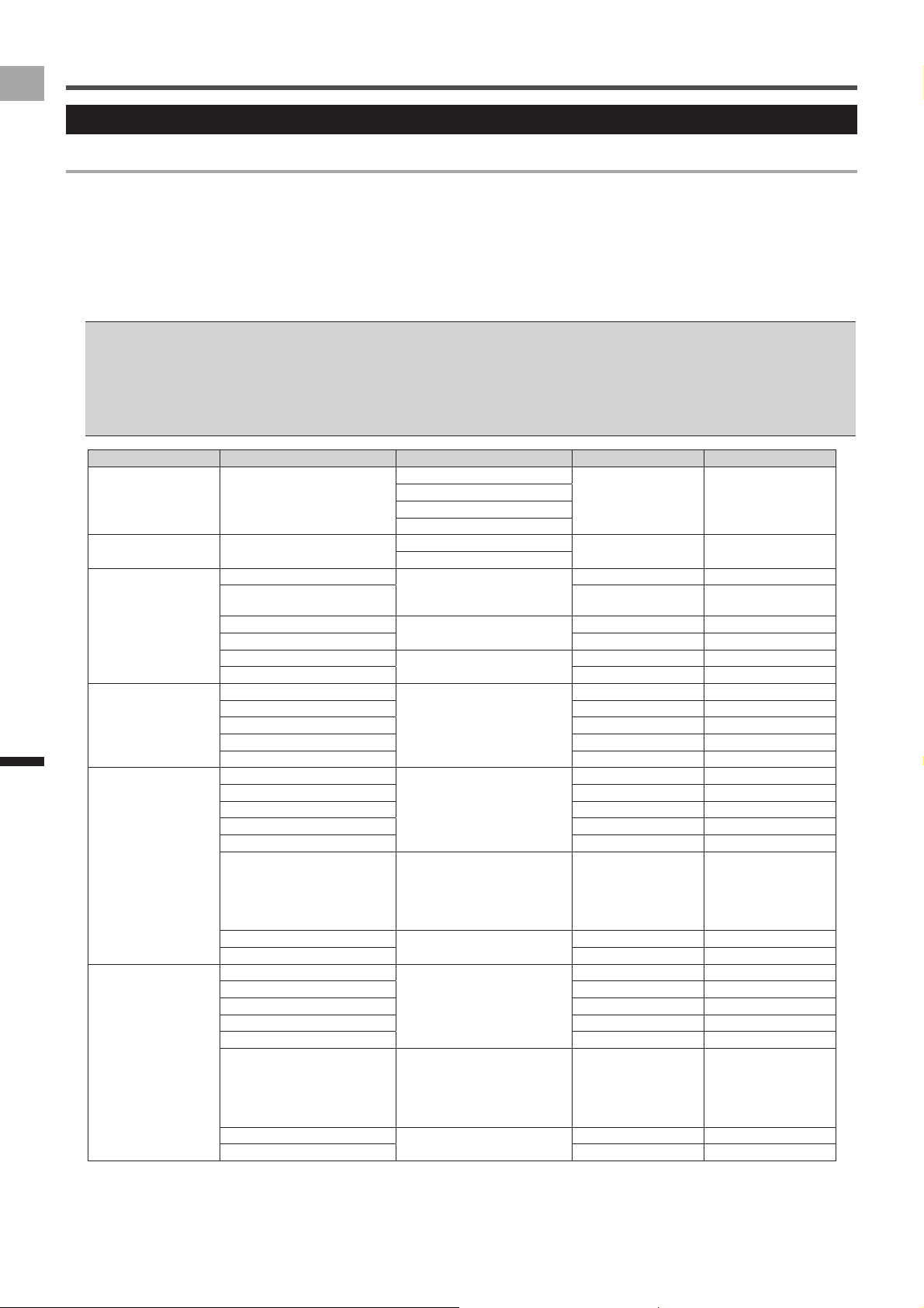
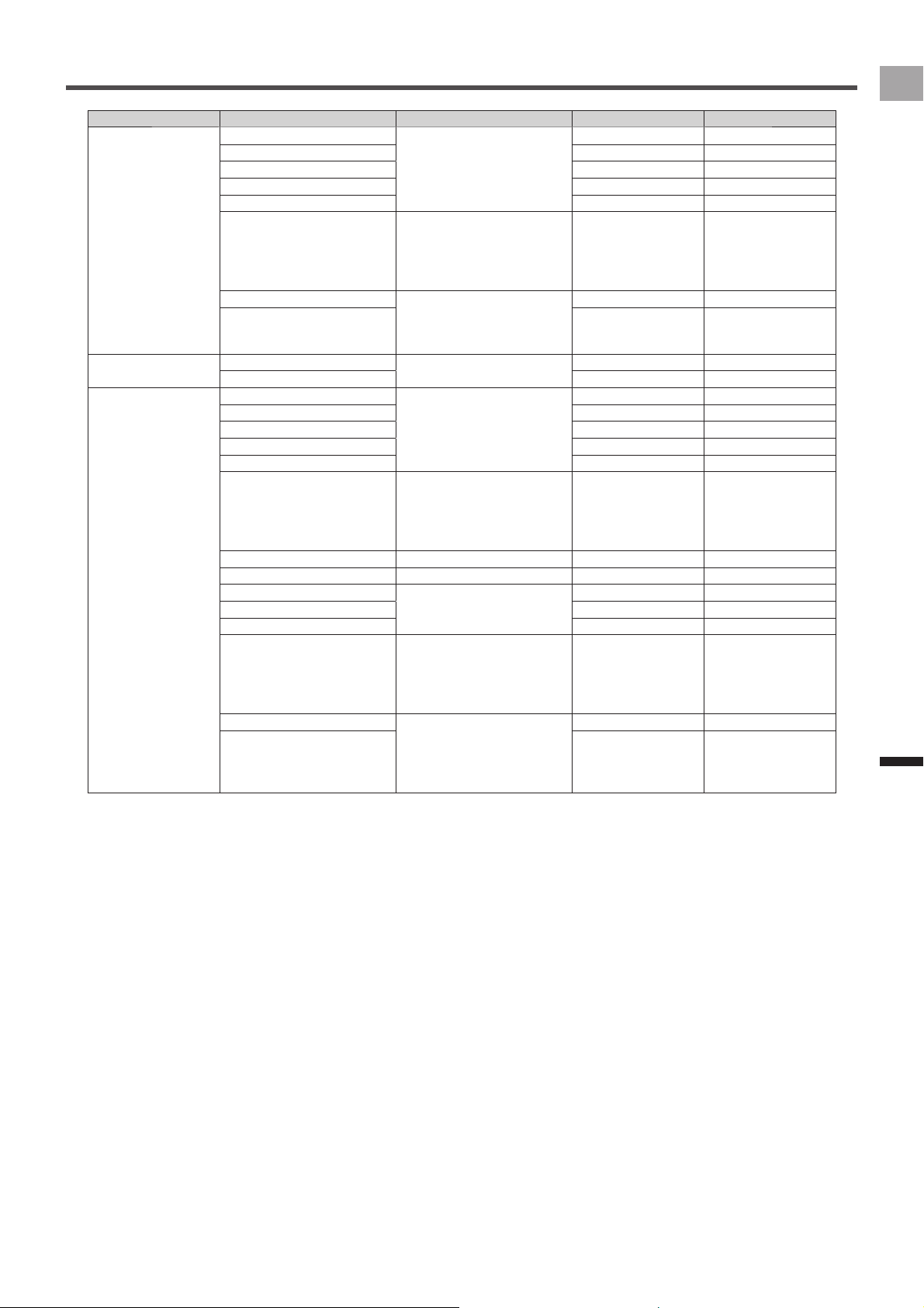
Data Field Type/Pattern List
Numerical type
Settings for the items in the table below can be configured for numerical type data fields.
Data Category•
Specifies the category of the display data.
Data Type•
Specifies the data type as average, maximum, etc.
Display Type•
Specifies the time display format, average value calculation range, etc.
Data types and display types that can be specified depend on the data category. If a setting cannot be changed, a setting screen does •
not appear when you tap an item.
Changes that can be made in labels, sub-labels, and units depend on the specified data category, data type, and display type.•
The data type and display type can also be changed while a data field is zoomed.•
«
Viewing Pages and Performing Page Operations (page 27)
The display type of the date and time, and the unit of measurement depends on the settings. For details about the settings, refer to •
“System” under “Cyclocomputer Settings” (
«
page 45).
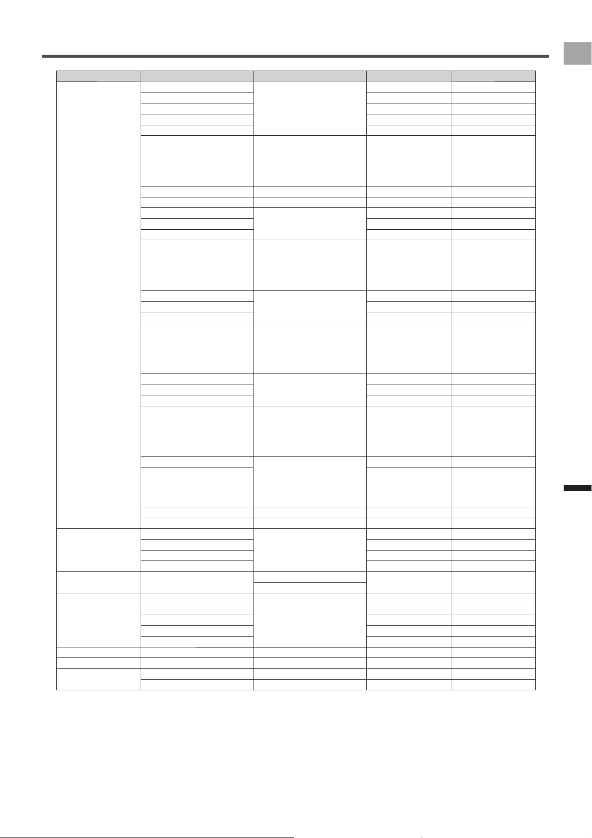
Data Category Data Type Display Type Label Sub-label
Date Date yyyy/MM/dd• Date ―
yyyy MMM dd•
MM/dd•
MMM dd•
Clock Time Clock Time hh:mm:ss• Clock ―
hh:mm•
Timer Time WO hh:mm:ss•
hh:mm•
Auto•
Time WO
Time Lap Time Lap
Total Time Bike d h•
h m•
Total Time Bike
Total Time Total Time Rider
Last LapTime hh:mm:ss• Time Last
Fastest Lap Best Lap ―
Distance Distance WO km or mile (*)• Dist WO
Distance Lap Dist Lap
Total Distance Bike Total Dist Bike
Total Distance Total Dist Rider
Distance Last Lap Dist Last
Speed Speed km/h or mph (*)• Speed ―
Speed WO Max Speed WO Mx
Speed Lap Max Speed Lap Mx
Speed WO Avg Speed WO Av
Speed Lap Avg Speed Lap Av
Speed n sec Avg 3s.Avg•
5s.Avg•
10s.Avg•
30s.Avg•
60s.Avg•
Speed Ns Av
Speed Last Lap Avg km or mile (*)• Speed Lst Av
Speed Last Lap Max Speed Lst Mx
Cadence Cadence rpm• Cadence ―
Cadence WO Max Cadence WO Mx
Cadence Lap Max Cadence Lap Mx
Cadence WO Avg Cadence WO Av
Cadence Lap Avg Cadence Lap Av
Cadence n sec Avg 3s.Avg•
5s.Avg•
10s.Avg•
30s.Avg•
60s.Avg•
Cadence Ns Av
Cadence Last Lap Avg rpm• Cadence Lst Av
Cadence Last Lap Max Cadence Lst Mx
* The display type unit depends on the specified unit of measurement. For details about unit of measurement settings, refer to
“System” under “Cyclocomputer Settings” (
«
page 45).
35
EN
Application
Transferring the Data
Data Category Data Type Display Type Label Sub-label
HeartRate HeartRate bpm•
%HRR•
%MAX•
ZONE•
Heart Rate ―
Heart Rate WO Max Heart Rate WO Mx
Heart Rate Lap Max Heart Rate Lap Mx
Heart Rate WO Avg Heart Rate WO Av
Heart Rate Lap Avg Heart Rate Lap Av
Heart Rate n sec Avg 3s.Avg•
5s.Avg•
10s.Avg•
30s.Avg•
60s.Avg•
Heart Rate Ns Av
Heart rate Last Lap Avg bpm•
%HRR•
%MAX•
ZONE•
Heart Rate Lst Av
Heart rate Last Lap Max Heart Rate Lst Mx
Calories Calories WO kcal• Calorie WO
Calories Lap Calorie Lap
Power Power Watt•
%FTP•
%CP•
LEVEL•
W/kg•
Power ―
Power WO Max Power WO Mx
Power Lap Max Power Lap Mx
Power WO Avg Power WO Av
Power Lap Avg Power Lap Av
Power n sec Avg 3s.Avg•
5s.Avg•
10s.Avg•
30s.Avg•
60s.Avg•
Power Ns Av
Work WO kJ• Work WO
Work Lap kJ• Work Lap
Power Balance %• Bal ―
Power Bal WO Avg Bal WO Av
Power Bal Lap Avg Bal Lap Av
Power Bal n sec Avg 3s.Avg•
5s.Avg•
10s.Avg•
30s.Avg•
60s.Avg•
Bal Ns Av
Last Lap Power Avg Watt•
%FTP•
%CP•
LEVEL•
W/kg•
Power Lst Av
Last Lap Power Max Power Lst Mx
* The display type unit depends on the specified unit of measurement. For details about unit of measurement settings, refer to
“System” under “Cyclocomputer Settings” (
«
page 45).
36
EN
Application
Transferring the Data
Data Category Data Type Display Type Label Sub-label
Pedaling L Power L Watt• Power L ―
Power L WO Max Power L WO Mx
Power L Lap Max Power L Lap Mx
Power L WO Avg Power L WO Av
Power L Lap Avg Power L Lap Av
Power L n sec Avg 3s.Avg•
5s.Avg•
10s.Avg•
30s.Avg•
60s.Avg•
Power L Ns Av
Loss L %• Loss L ―
Loss L WO Avg Loss L WO Av
Loss L Lap Avg Loss L Lap Av
Loss L n sec Avg 3s.Avg•
5s.Avg•
10s.Avg•
30s.Avg•
60s.Avg•
Loss L Ns Av
Efficiency L %• Eff L ―
Efficiency L WO Avg Eff L WO Av
Efficiency L Lap Avg Eff L Lap Av
Efficiency L n sec Avg 3s.Avg•
5s.Avg•
10s.Avg•
30s.Avg•
60s.Avg•
Eff L Ns Av
Power L Last Lap Avg Watt• Power L Lst Av
Power L Last Lap Max Power L Lst Mx
Pedaling R Power R Watt• Power R ―
Power R WO Max Power R WO Mx
Power R Lap Max Power R Lap Mx
Power R WO Avg Power R WO Av
Power R Lap Avg Power R Lap Av
Power R n sec Avg 3s.Avg•
5s.Avg•
10s.Avg•
30s.Avg•
60s.Avg•
Power R Ns Av
Loss R %• Loss R ―
Loss R WO Avg Loss R WO Av
Loss R Lap Avg Loss R Lap Av
Loss R n sec Avg 3s.Avg•
5s.Avg•
10s.Avg•
30s.Avg•
60s.Avg•
Loss R Ns Av
Efficiency R %• Eff R ―
Efficiency R WO Avg Eff R WO Av
Efficiency R Lap Avg Eff R Lap Av
Efficiency R n sec Avg 3s.Avg•
5s.Avg•
10s.Avg•
30s.Avg•
60s.Avg•
Eff R Ns Av
Power R last Lap Avg Watt• Power R Lst Av
Power R last Lap Max Power R Lst Mx
* The display type unit depends on the specified unit of measurement. For details about unit of measurement settings, refer to
“System” under “Cyclocomputer Settings” (
«
page 45).
37
EN
Application
Transferring the Data
Data Category Data Type Display Type Label Sub-label
Pedaling LR Power LR Watt•
%FTP•
%CP•
LEVEL•
W/kg•
Power LR ―
Power LR WO Max Power LR WO Mx
Power LR Lap Max Power LR Lap Mx
Power LR WO Avg Power LR WO Av
Power LR Lap Avg Power LR Lap Av
Power LR n sec Avg 3s.Avg•
5s.Avg•
10s.Avg•
30s.Avg•
60s.Avg•
Power LR Ns Av
Work LR WO kJ• Work LR WO
Work LR Lap kJ• Work LR Lap
Loss LR %• Loss LR ―
Loss LR WO Avg Loss LR WO Av
Loss LR Lap Avg Loss LR Lap Av
Loss LR n sec Avg 3s.Avg•
5s.Avg•
10s.Avg•
30s.Avg•
60s.Avg•
Loss LR Ns Av
Efficiency LR %• Eff LR ―
Efficiency LR WO Avg Eff LR WO Av
Efficiency LR Lap Avg Eff LR Lap Av
Efficiency LR n sec Avg 3s.Avg•
5s.Avg•
10s.Avg•
30s.Avg•
60s.Avg•
Eff LR Ns Av
Power Balance %• Bal L:R ―
Power Bal WO Avg Bal L:R WO Av
Power Bal Lap Avg Bal L:R Lap Av
Power Bal n sec Avg 3s.Avg•
5s.Avg•
10s.Avg•
30s.Avg•
60s.Avg•
Bal L:R Ns Av
Power LR Last Lap Avg Watt•
%FTP•
%CP•
LEVEL•
W/kg•
Power LR Lst Av
Power LR Last Lap Max Power LR Lst Mx
Effciency LR Last Lap Avg %• Eff LR Lst Av
Power Bal Last Lap Avg %• Bal L:R Lst Av
Temperature Temperature °C or °F (*)• Temp ―
Temperature WO Max Temp WO Mx
Temperature WO Min Temp WO Min
Temperature WO Avg Temp WO Av
Atmosphere Atmosphere HPa
• Atm ―
atm•
Altitude Altitude m or ft (*)• ALT ―
Elevation Gain WO Elev Gain WO
Elevation Gain Lap Elev Gain Lap
Elevation Loss WO Elev Loss WO
Elevation Loss Lap Elev Loss Lap
Grade Grade %• Grade ―
Lap Count Lap Count Count• Lap ―
GPS Latitude Latitude• Lat ―
Longitude Longitude• Lon ―
* The display type unit depends on the specified unit of measurement. For details about unit of measurement settings, refer to
“System” under “Cyclocomputer Settings” (
«
page 45).
38
EN
Application
Transferring the Data
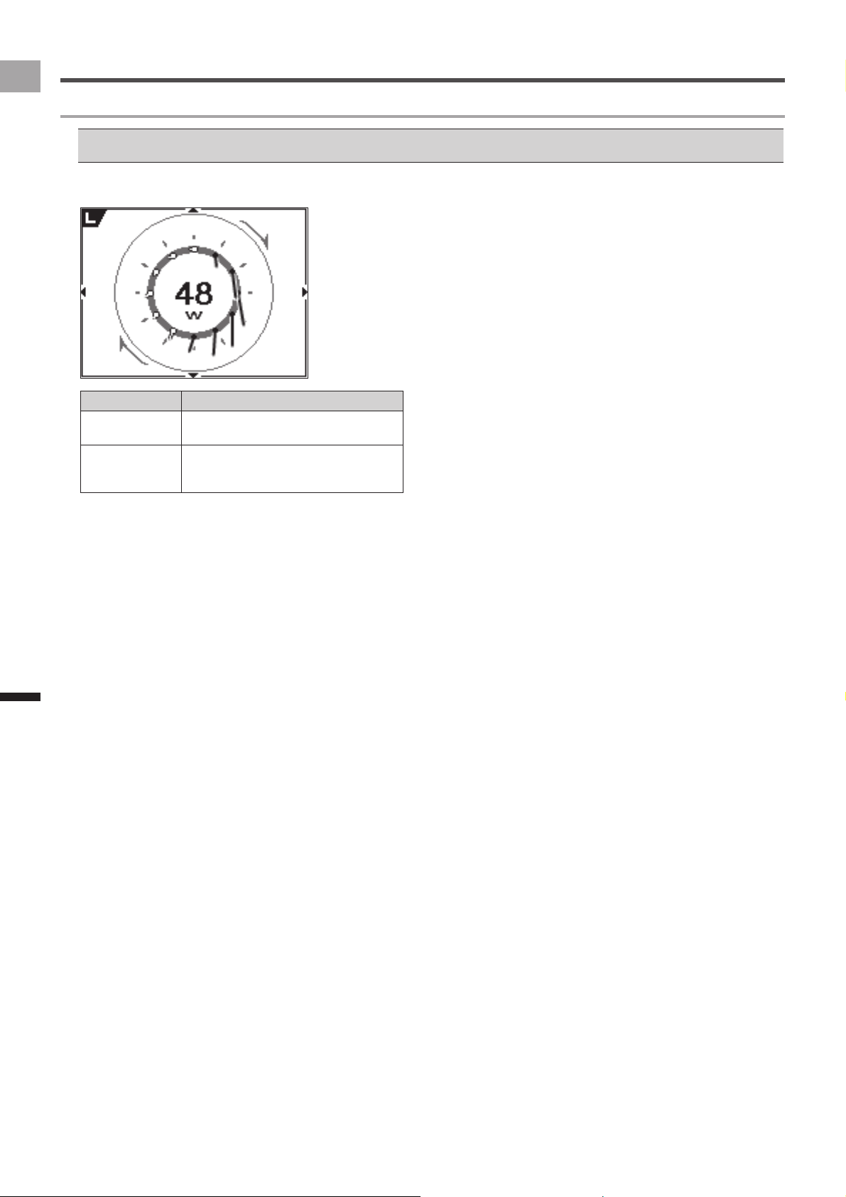
Pedaling Chart
■
Item Parameter
View Mode Vector Chart•
Torque Chart•
View Side Left•
Right•
Right & Left•
Graph type
The graph type data field may be limited to the size of the data field that can be inserted.•
«
Layout Pattern List (page 33)
39
EN
Application
History Viewer
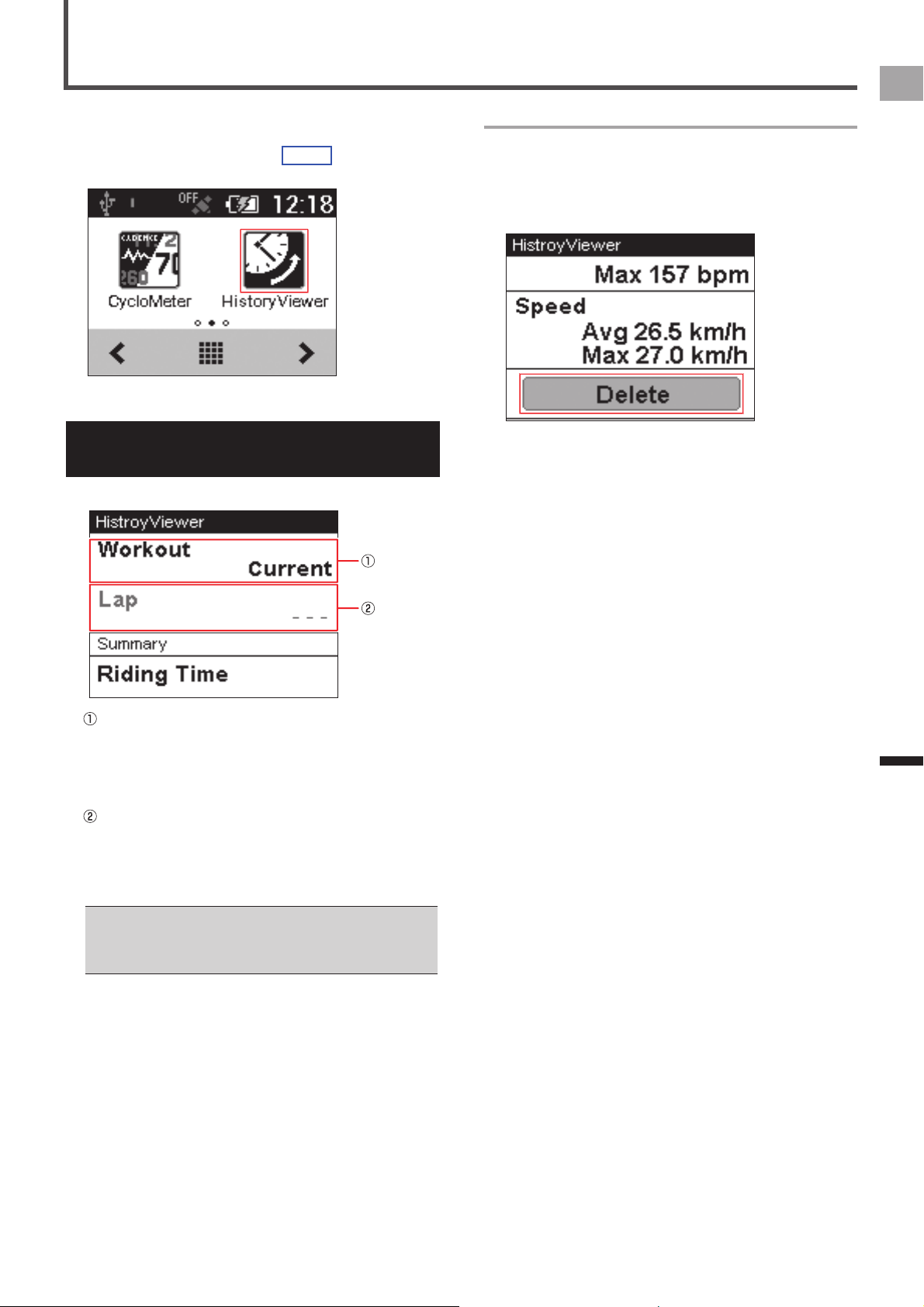
History Viewer is an application for viewing workout logs.
You can use it to view a summary of each lap, totals, etc.
You can activate History Viewer by tapping the History
Viewer icon on the home or launcher screen.
Viewing the Screen and
Performing Screen Operations
Starting up History Viewer displays workout history data.
Changes the workout
Tap to change displayed history workout data.
Tapping this button displays a list of workouts. The
check box of the workout whose history data is
currently displayed will be selected.
Changes the lap
Tap to change the lap whose history data is displayed.
Tapping this button displays a list of workouts. The
check box of the lap whose history data is currently
displayed will be selected.
While the device is connected to a PC with the USB cable, •
the workout or lap is unable to change.
To end [History Viewer], press and hold the [MENU] button •
on the [History Viewer] screen.
Deleting history data
Selecting the history data other than [Current] displays
the [Delete] button at the bottom of the list on the [History
Viewer] screen.
Tap the [Delete] button to delete the history data from the
device.
40
EN
Application
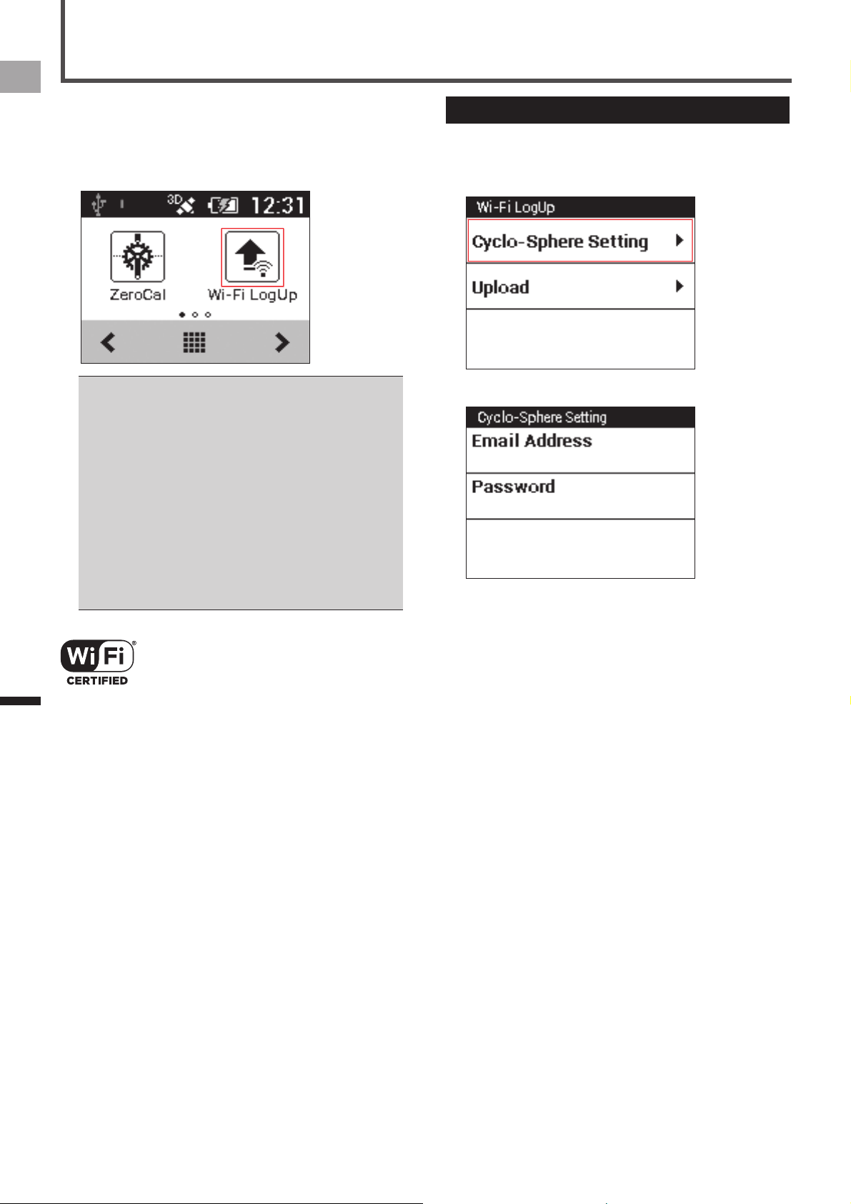
Wi-Fi LogUp
Wi-Fi LogUp is an application for uploading the log data in
the device to the Cyclo-Sphere analysis service via Wi-Fi.
The log data can be uploaded easily, without connecting the
device to a PC.
The device’s Wi-Fi settings must be done before uploading •
the log data via Wi-Fi.
«
Wi-Fi Settings (page 44)
You must register as a user of Cyclo-Sphere. Refer to the •
Cyclo-Sphere website for details.
https://cyclo-sphere.com/
The log data upload via Wi-Fi is not available when the •
device is connected to a PC or other device via a USB
cable.
The device is compatible with the WEP and WPA/WPA2 •
PSK standards.
The device is not compatible with the LAN stealth functions •
of routers and access points. Routers and access points in
stealth mode do not appear on the device’s connection list.
The device cannot connect to access points that require you •
to enter account information in an internet browser.
Wi-Fi Certified and the logo are trademarks or registered
trademarks of the Wi-Fi Alliance.
Cyclo-Sphere Settings
Specify a user account in Cyclo-Sphere to upload log data
via Wi-Fi.
1
Tap [Cyclo-Sphere Setting].
2
Input an e-mail address and password.
41
EN
Application
Wi-Fi LogUp
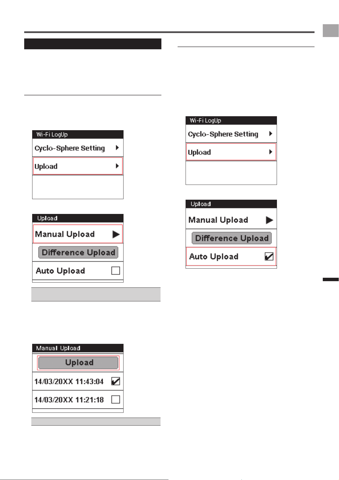
Log Data Upload
Use the procedure below to upload the log data in the device
via Wi-Fi.
There are two upload methods, they are manual upload and
auto upload.
Manual Upload
Select the log data from the log data list to upload to Cyclo-
Sphere. You can also upload all log data not previously
uploaded to Cyclo-Sphere.
1
Tap [Upload].
2
Tap [Manual Update].
Tap [Difference Upload] to upload all log data not previously •
uploaded to the Cyclo-Sphere.
3
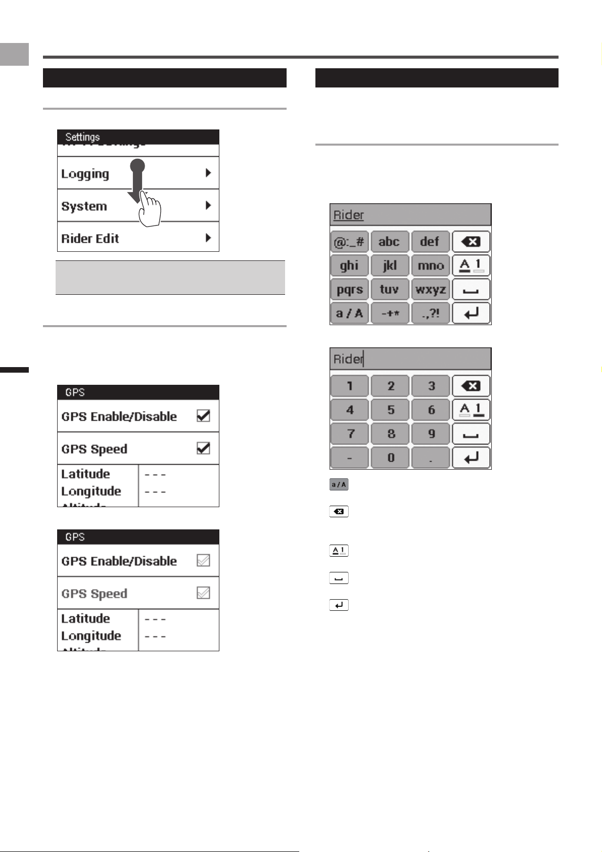
Tap the log data you want to upload, and then
tap [Upload].
The device starts to connect to Wi-Fi and upload the log
data automatically. After finishing log data upload, the
Wi-Fi connection is disconnected.
The [↑] icon is displayed for the uploaded files.•
Auto Upload
If the Auto Upload function is set to on, the Wi-Fi connection
is started automatically after the timer is reset to stop
logging, and then the log data is uploaded to Cyclo-Sphere.
If log data not previously uploaded to Cyclo-Sphere is
found before logging starts or while logging is stopped, the
device checks the Wi-Fi connection periodically, and when
a connection is available, uploads the log data to Cyclo-
Sphere in the background.
1
Tap [Upload].
2
Tap the [Auto Upload] check box.
42
EN
Application
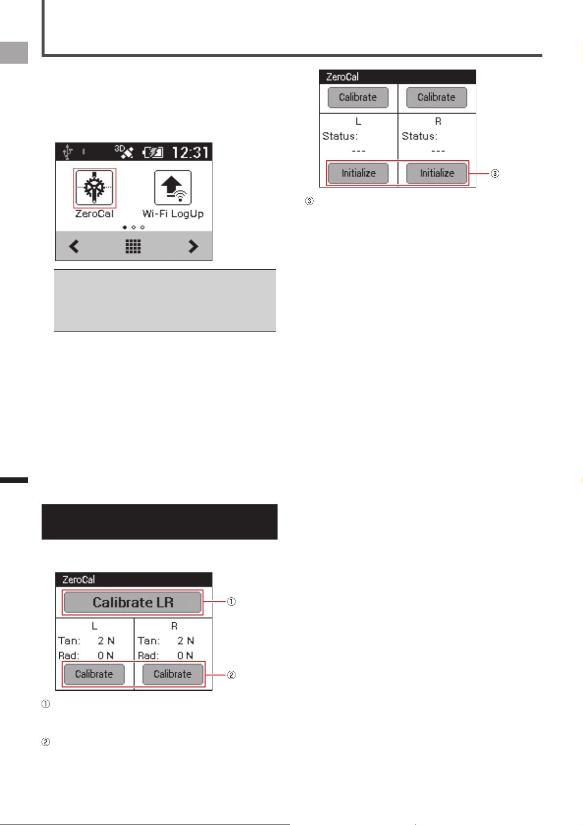
ZeroCal
ZeroCal is an application for calibrating the zero point of the
left and right sensors of the Pedaling Monitor Sensor SGY-
PM910H/PM900H series.
With these simple procedures, you can calibrate the zero
point, check the force preview, and clear the temperature
learning data of both the left and right sides.
The zero point calibration with ZeroCal is available only •
when the device is paired with one of the products in the
Pedaling Monitor Sensor SGY-PM910H/PM900H series.
If you initialize with ZeroCal, the learned data of the function •
to calibrate the zero point as the temperature changes is
cleared.
About the temperature (air temperature)
■
learning function
This device uses the temperature (air temperature) learning
function to automatically calibrate its zero point as the
temperature changes. This function maintains accuracy as
the temperature changes during a ride.
As the temperature varies, it is necessary to calibrate the
zero point more than twice, so the most recent six times are
used for calibrating using this function.
The results of the zero point calibration are recorded if the
temperature varies more than 4 °C from the zero point
calibration recorded previously.
Viewing the Screen and
Performing Screen Operations
Starting up ZeroCal displays various buttons, and the screen
for the force preview and results of the calibration.
[Calibrate LR]:
Tap to calibrate the zero point of both the left and right
sides.
Force preview:
Displays the force preview of the left and right sides.
Tapping [Calibrate] enables you to calibrate the zero
point of the left or right side separately.
[Initialize]:
Tapping [Initialize] clears the learned data of the function
to calibrate the zero point as the temperature changes.
43
EN
Settings
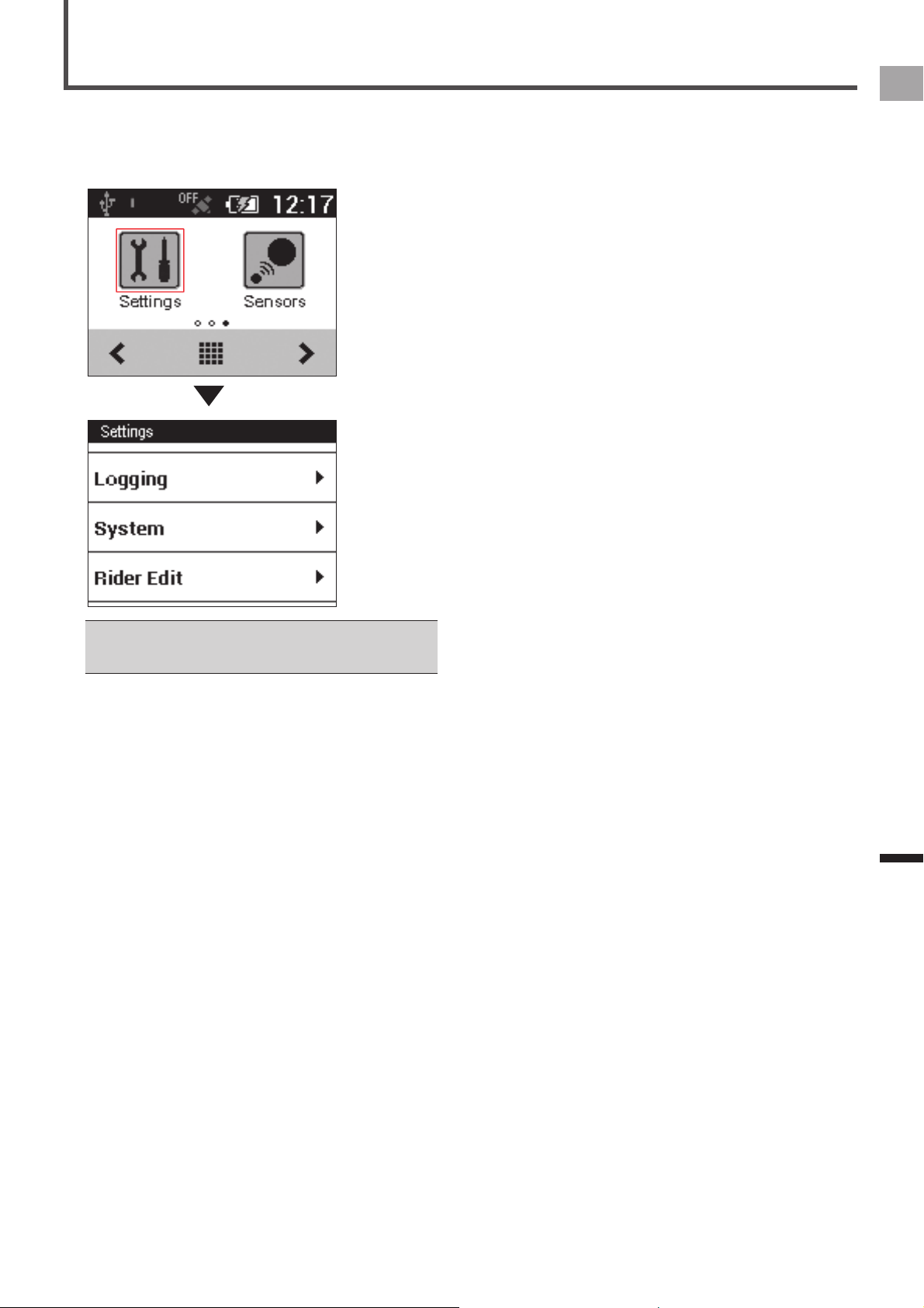
Cyclocomputer Settings
Configure Cyclocomputer settings using the "Settings"
menu.
To display the Settings menu, tap the [Settings] icon on the
home screen.
You can also display the Settings menu while CycloMeter •
is running by pressing the [MENU] button and then tapping
[Settings].
The settings listed below can be configured with the Settings
menu.
Bike Select (•
«
page 44)
Wi-Fi Settings (•
«
page 44)
Logging (•
«
page 45)
System (•
«
page 45)
Rider Edit (•
«
page 49)
Bike Edit (•
«
page 49)
44
EN
Settings
Cyclocomputer Settings
Bike Select
Use the setting below to change the bike being used.
Setting Item Description
(Bike name) Change the bike being used. The device can have up to six bikes registered to it.
If the bike is changed, the registered sensor setting will also change automatically. When you change the bike, make sure that the •
sensor is connected with the device.
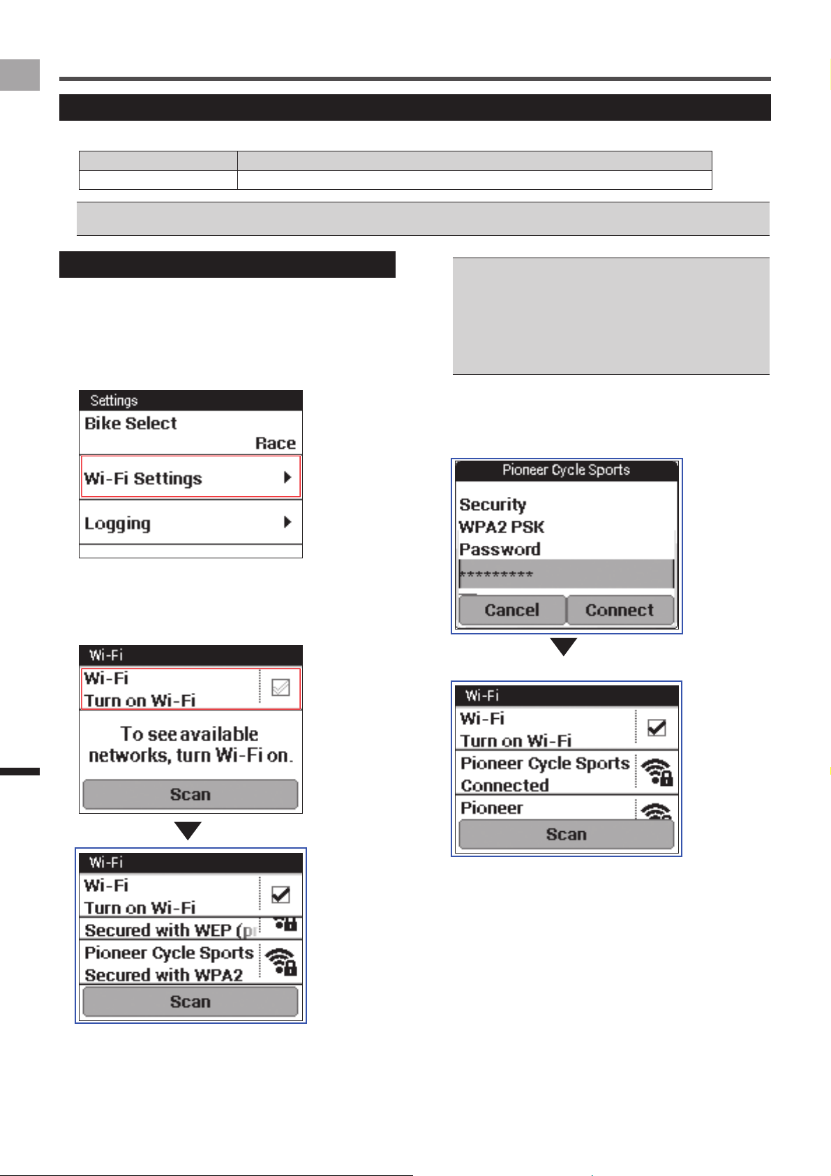
Wi-Fi Settings
Configure Wi-Fi settings, such as switching the Wi-Fi
connection and adding an access point.
1
On the home screen, tap the [Settings] icon.
This displays the settings menu.
2
Tap [Wi-Fi Settings].
3
Tap the [Wi-Fi] check box.
The Wi-Fi function is turned on and scanning for an
access point starts.
A list appears when access points are found.
Tap [Scan] to reload the list. •
The device is compatible with the WEP and WPA/WPA2 •
PSK standards.
The device is not compatible with the LAN stealth functions •
of routers and access points. Routers and access points in
stealth mode do not appear on the device’s connection list.
The device cannot connect to access points that require you •
to enter account information in an internet browser.
4
Tap the access point you want to add.
This displays network information. Input the password
and other required information, and then tap [Connect] to
start connecting.
45
EN
Settings
Cyclocomputer Settings
Logging
Use the settings below to configure the logging operation.
Settings marked with an asterisk (*) are initial factory defaults.
Setting Item Description
Auto Lap Enable or disable* Auto Lap.
Select the check box to enable Auto Lap.
«
Auto Lap Settings (page 24)
Auto Pause/Resume Enable* or disable Auto Pause/Resume.
Select the check box to enable Auto Pause/Resume.
«
Auto Pause/Resume Settings (page 22)
Trigger Threshold Specify the Auto Pause/Resume speed threshold value.
Logging Interval Specify the logging interval.
Specifying [Auto] causes the logging interval to be adjusted automatically within a range 1 to
10 seconds in accordance with riding speed.
Auto•
1 sec*•
3 sec•
5 sec•
10 sec•
Reminder Enable or disable* Reminder.
Select the check box to enable Reminder.
«
Reminder Settings (page 23)
System
Use the settings below to configure Cyclocomputer system-wide settings.
Settings marked with an asterisk (*) are initial factory defaults.
Setting Item Description
GPS GPS Enable/Disable Enables* and disables GPS.
Check the box to reflect time information from GPS to the date and time of the
device.
GPS Speed Switches GPS Speed function on* or off. Check the box to display speed and
distance obtained from GPS.
You can select this function only when [GPS Enable/Disable] is on. Errors may
occur between displayed value and actual value depending on the signal. If the
speed sensor is connected, the value from the sensor is displayed as a priority.
(GPS status) Displays the GPS position status (no positioning, 2D, 3D).
Battery (Battery status) Shows the device remaining battery charge and charge condition.
«
Checking the Battery Level (page 6)
Charge Mode Specify the charging mode setting.
Normal Charge*•
Boost Charge•
«
Charging Mode Setting (page 7)
Sound Audio Volume Adjust the device speaker volume to one of six levels.
0 - 3* - 5•
Audible Selection Turn the audible selection tone for touch panel menu item selection on* or off.
Audible selection is turned on when the check box is selected.
Display Brightness Adjust the display brightness.
Touch the screen, adjust brightness, and then tap [OK].
Contrast Adjust the display contrast.
Touch the screen, adjust contrast, and then tap [OK].
Touchscreen Calibration Calibrate the touch panel.
«
Calibrating the Touch Panel (page 47)
Altitude Calibration Current Altitude Displays the current altitude.
Calibration Type Specify the altitude calibration type.
Current Altitude*•
Sea-level Pressure•
GPS•
Setting Value Enter an altitude setting value.
Calibration Tap to calibrate the altitude.
46
EN
Settings
Cyclocomputer Settings
Setting Item Description
Language Specify the device’s display language.
Deutsch•
English•
Español•
Français•
Italiano•
Nederlands•
•
Date & Time Time Zone Specify a time zone.
Date Set the current date.
Time Set the current time.
24-Hour Format Select the check box to display time in 24-hour format.
Date Format Select a date display format.
Units Distance Specify a distance display unit.
km*•
mile•
Altitude Specify an altitude display unit.
meter*•
feet•
Temperature Specify a temperature display unit.
Celsius*•
Fahrenheit•
Weight Specify a weight display unit.
kg*•
lb•
Setting Manager Initialize Initialize system and application settings.
«
Initialize (page 53)
Backup Saves system and application settings as backup data.
«
Backup (page 54)
Restore Restores system and application settings using backed up data.
«
Restore (page 55)
Firmware Update Updates the device's firmware.
«
Update (page 56)
License Displays device license information.
Firmware Version Displays firmware version information.
Serial Number Displays the device serial number.
Wi-Fi MAC address Displays the Wi-Fi MAC address.
Memory Format Format the built-in flash memory.
«
Built-in Flash Memory Format (page 48)
Service Code Input the service code and change the device mode.
47
EN
Settings
Cyclocomputer Settings
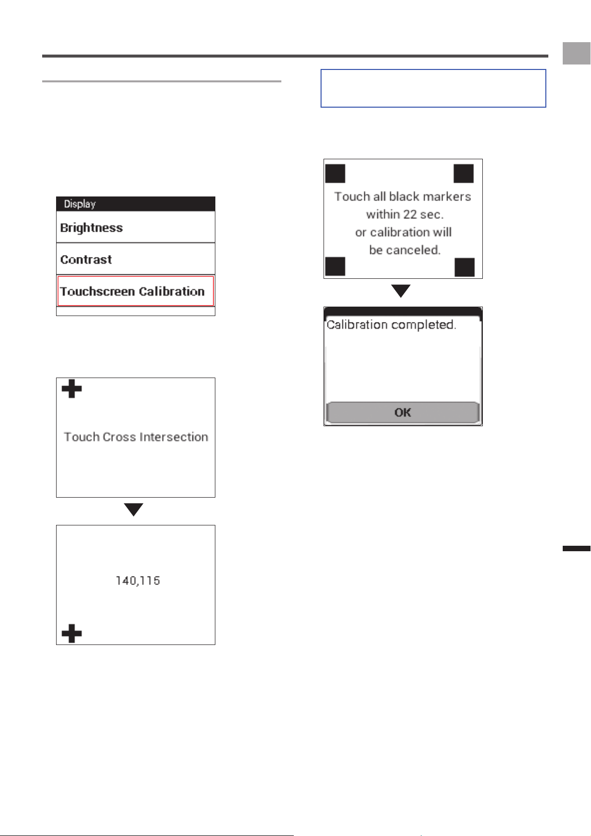
Calibrating the Touch Panel
Use the procedure below to calibrate the touch panel to
ensure correct response when you touch the screen with
your finger.
1
On the home screen, tap the [Settings] icon.
2
Tap [System] - [Display] - [Touchscreen
Calibration].
This displays the touch panel calibration screen, with a
cross mark on it.
3
Tap the center of the cross mark.
This causes another cross mark to appear. Tap the
center of the next cross mark. A total of five cross marks
appear on the screen.
4
Tap all four square marks within 30 seconds.
Touch panel calibration will be completed after tapping
the four square marks within the allowed time.
After the message "Calibration completed." appears, tap
[OK].
Touch panel calibration will be exited if you do not tap it
within the allowed time.

48
EN
Settings
Cyclocomputer Settings
Built-in Flash Memory Format
Format the built-in flash memory.
All data in the built-in flash memory will be erased when it is •
formatted.
When the device is connected to the PC with USB cable, •
disconnect it before you format the flash memory.
1
On the home screen, tap the [Settings] icon.
2
Tap [System] - [Memory Format].
The confirmation message is displayed to check if you
format it or not.
3
Tap [OK].
The format starts.
When the format is completed, the message is displayed.
Tap [OK] to finish the format.
49
EN
Settings
Cyclocomputer Settings
Rider Edit
Use the settings below to register and edit rider information.
Correctly configured rider information is required in order to obtain accurate data.•
Setting Item Description
Total Distance Displays the total distance that the rider has traveled with all six bikes.
Total Time Displays the total time that the rider has traveled with all six bikes.
Name Specify the rider name.
Height Specify the rider height.
Weight Specify the rider body weight.
Birth Year Specify the rider date of birth.
Sex Specify the rider gender.
FTP Specify the rider FTP (Functional Threshold Power: maximal power output that can be
sustained for one hour).
CP Specify the rider CP (Critical Power).
AWC Specify the rider AWC (Anaerobic Work Capacity).
Heart Rate Max Specify the rider maximum heart rate during exercise. (*)
Heart Rate Min Specify the rider stable heart rate at rest.
VO2MAX Specify the rider VO2MAX.
* The maximum heart rate is an indicator of exercise load. A guideline for maximum heart rate is (220 - age).
Bike Edit
Use the settings below to register and edit bike information.
Correctly configured bike information is required in order to obtain accurate data.•
The device can have up to six bikes registered to it. You can use the procedure under "Bike Select" (•
«
page 44) to change to one of the
registered bikes.
The riding distance and time of the bike are added automatically after this setting.•
Setting Item Description
Bike 1,
Bike 2,
Bike 3,
Bike 4,
Bike 5,
Bike 6
Sensors Edit sensors connected to bike.
«
Sensor Settings (page 50)
Wheel Circumference Specify the bike wheel circumference.
Input the circumference of the wheel attached with the tire.
Total Distance Bike Specify the bike riding distance.
Total Time Bike Specifies total time ridden on each bike.
Name Specify the name of the bike.
Weight Specify the weight of the bike.
Crank Length Specify the crank length.
Saddle Height Specify the saddle height.
Saddle Setback Specify the saddle setback.
Stem Length Specify the stem length.
Handlebar Position Specify the handlebar position.
Frame Size Specify the frame size.
Chainrings Specify the chain ring size.
Sprocket Specify the number of sprocket teeth.
Wheel Specify the wheel type.
50
EN
Settings
Sensor Settings
Sensor On/Off
Use the procedure below to turn sensors connected to the
bike on or off.
1
On the home screen, tap the [Sensors] icon.
This displays the sensor list.
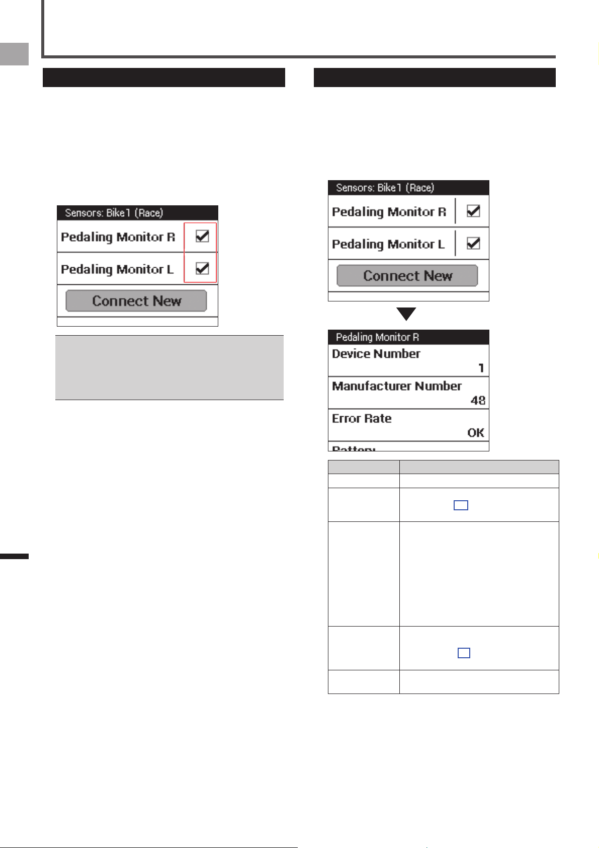
2
Tap a sensor check box to toggle it between on
and off.
A sensor connection is turned on if its check box is
selected.
You can check information about a sensor by tapping its •
sensor name.
Sensor settings need to be configured for each bike. If this •
device has multiple bikes registered, you need to configure
sensor settings for each of the registered bikes.
«
Bike Select (page 44)
Checking Sensor Information
Use the procedure below to check connected sensor device
information and to check the status of a sensor.
1
On the home screen, tap the [Sensors] icon.
This displays the sensor list.
2
Tap the sensor you want to check.
This displays sensor information.
Setting Item Description
Device Number Shows the sensor device number.
Manufacturer
Number
Shows the sensor manufacturer ID.
It is not shown for a speed & cadence
sensor.
Error Rate Shows the error rate of data received from
the sensor.
OK:•
It is receiving the data properly from the
sensor.
Not connected:•
Sensor connection is disabled.
Processing...:•
Sensor connection is enabled and the
device is searching for the sensor.
Battery Shows the sensor battery voltage when the
sensor is connected.
It is shown only for PowerMeter, Pedaling
Monitor L, or Pedaling Monitor R.
Delete Tap to delete the sensor from the sensor
list.

51
EN
Settings
Sensor Settings
Sensor Calibration
A calibration menu is also displayed in sensor information when the sensor device type is [Pedaling Monitor L], [Pedaling
Monitor R], or [Power].
When the device type is [Pedaling Monitor L] or [Pedaling Monitor R]
■
The items shown below are displayed in sensor information.
Setting Item Description
Force Preview Tangential Direction
Force
Shows the tangential load.
Radial Direction Force Shows the radial load.
Calibration (Zero) Start Calibration Tap to start calibration.
Status Shows the calibration status (Unknown, Processing..., Process done).
Result Shows the calibration result (Success, Failure).
Data (Tangential) Shows tangential data obtained from calibration.
Data (Radial) Shows radial data obtained from calibration.
Error Code Displays the error code that indicates the cause when the sensor calibration is
failed.
For information about how to calibrate the Pedaling Monitor Sensor series SGY-PM910H/PM900H, refer to the Installation Manual or the •
User's Manual that comes with the Pedaling Monitor Sensor series SGY-PM910H/PM900H.
When the device type is [Power]
■
The items shown below are displayed in sensor information.
Setting Item Description
Calibration Start Calibration Tap the button to start PowerMeter calibration.
Status Shows the calibration status.
Result Shows the calibration result (Success, Failure).
Data Shows data obtained from calibration.
Auto Calibration Specify the auto calibration function when the Power Meter is compatible with
the auto calibration function.
Torque Displays the torque value when the Power Meter is programmed to output the
torque value.
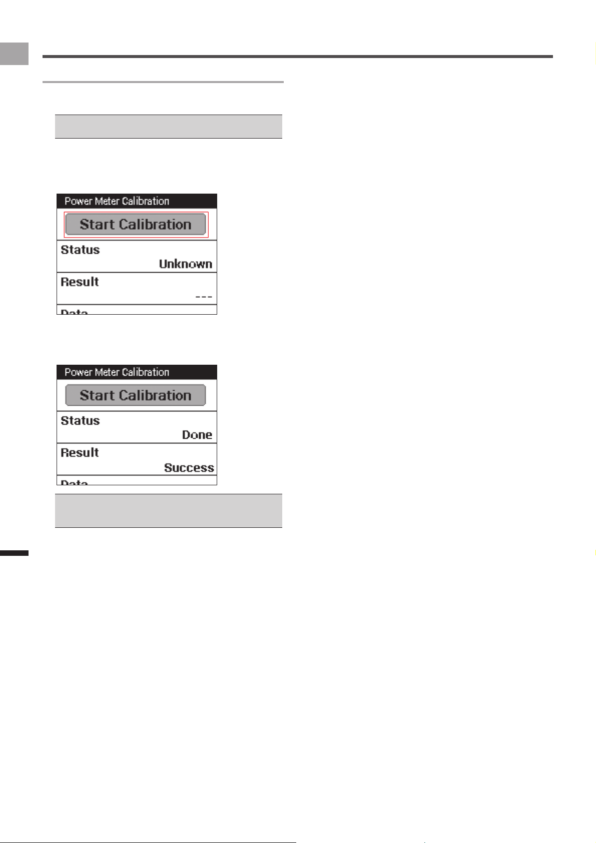
52
EN
Settings
Sensor Settings
Performing PowerMeter Calibration
PowerMeter calibration ensures that PowerMeter information
is received correctly.
Refer to the PowerMeter Installation Manual for information •
about mounting PowerMeter.
1
On the home screen, tap the [Sensors] icon.
2
Tap [Power] - [Calibration] - [Start Calibration].
This starts PowerMeter calibration.
3
Check the calibration result.
Calibration is complete when "Success" is shown in the
[Result] field.
If "Failure" is shown, it means that calibration was not •
performed correctly for some reason. Refer to the sensor
user’s manuals.
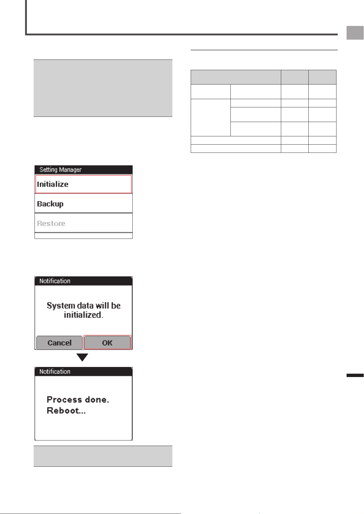
53
EN
Management
Initialize
Initialize returns the device system and application settings
to their initial factory defaults.
If the device is connected to a PC with the USB cable, •
disconnect the USB cable from the PC before initializing. If
the device is logging, stop logging and save the log data.
Initializing the device will cause all system data to be lost. •
Backup of data is recommended prior to initialization.
Also note that initialization deletes backup data stored in
device flash memory. Before initialization, be sure to move
backup data to a PC or other media storage device.
«
Backup (page 54)
1
On the home screen, tap the [Settings] icon.
This displays the settings menu.
2
Tap [System] - [Setting Manager] - [Initialize].
This will display a confirmation message asking if you
want to initialize system data.
3
Tap [OK].
This starts system data initialization.
The message will appear when initialization is complete
and the device restarts automatically.
After the device restarts, the Initial Setup screen will appear. •
Configure initial settings.
«
Initial Setup (page 12)
Initialized, Backed Up, and Restored Data
The table below shows what settings are affected by
initialize, backup, and restore operations.
Description Initialize Backup/
Restore
Home screen
settings
Shortcut icon
arrangement
○○
Cyclocomputer
Settings
Date/Time ‒‒
Touchscreen
Calibration
‒○
Settings other than
those above.
○○
CycloMeter settings ○○
CycloMeter riding log ○‒

54
EN
Management
Backup
Backup creates backup data for system and application
settings.
You can use backup data to restore the system after
initializing it following a system error, etc.
If the device is connected to the PC with the USB cable, •
disconnect it before performing a backup. If the device is
logging, stop logging and save the log data.
For information about what data is backed up, refer to •
"Initialized, Backed Up, and Restored Data" under "Initialize"
(
«
page 53).
Riding log data is not included in backed up data. Save •
riding log data separately to a PC.
«
Transferring the Data (page 26)
1
On the home screen, tap the [Settings] icon.
This displays the settings menu.
2
Tap [System] - [Setting Manager] - [Backup].
This will display a confirmation message asking if you
want to create backup data.
3
Tap [OK].
This starts backup data creation.
The message will appear when the backup data is
created. Tap [OK] to exit backup.
4
Connect the device to your PC.
Connect the provided USB cable to a computer's USB
connector.
For information about connections, refer to "Charging the
Device" under "Charging" (
«
page 6).
5
Save the backup data where you want on the
PC.
The backup data is stored in the device built-in flash
memory in a folder named "\Pioneer\Setting\".
Note that backup data stored in device flash memory is •
deleted whenever the device is initialized. Be sure to save
the backup data to a PC or other media.
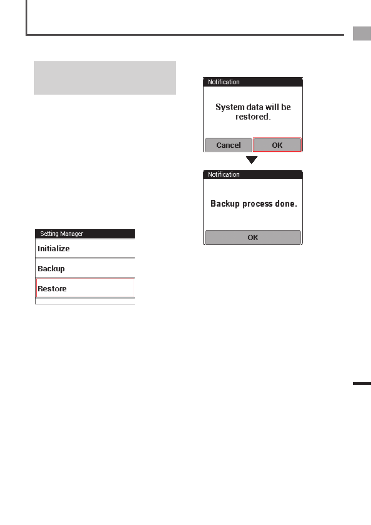
55
EN
Management
Restore
Backup data is used to restore the system after initializing it
following a system error, etc.
If a logging operation is in progress on the device, stop •
logging and save the log data before performing the restore.
For information about what data is restored, refer to •
"Initialized, Backed Up, and Restored Data" under "Initialize"
(
«
page 53).
1
Connect the device to your PC.
Connect the provided USB cable to a computer's USB
connector.
For information about connections, refer to "Charging the
Device" under "Charging" (
«
page 6).
2
Copy the backup data to the device.
Copy the backup data from your PC to the folder in the
device built-in flash memory named "\Pioneer\Setting\".
3
Unplug the USB cable from the device's USB
connector.
4
On the home screen, tap the [Settings] icon.
This displays the settings menu.
5
Tap [System] - [Setting Manager] - [Restore].
This will display a confirmation message asking if you
want to restore system data.
6
Tap [OK].
This starts system data restore.
The message will appear when restoring is complete and
the device restarts automatically.
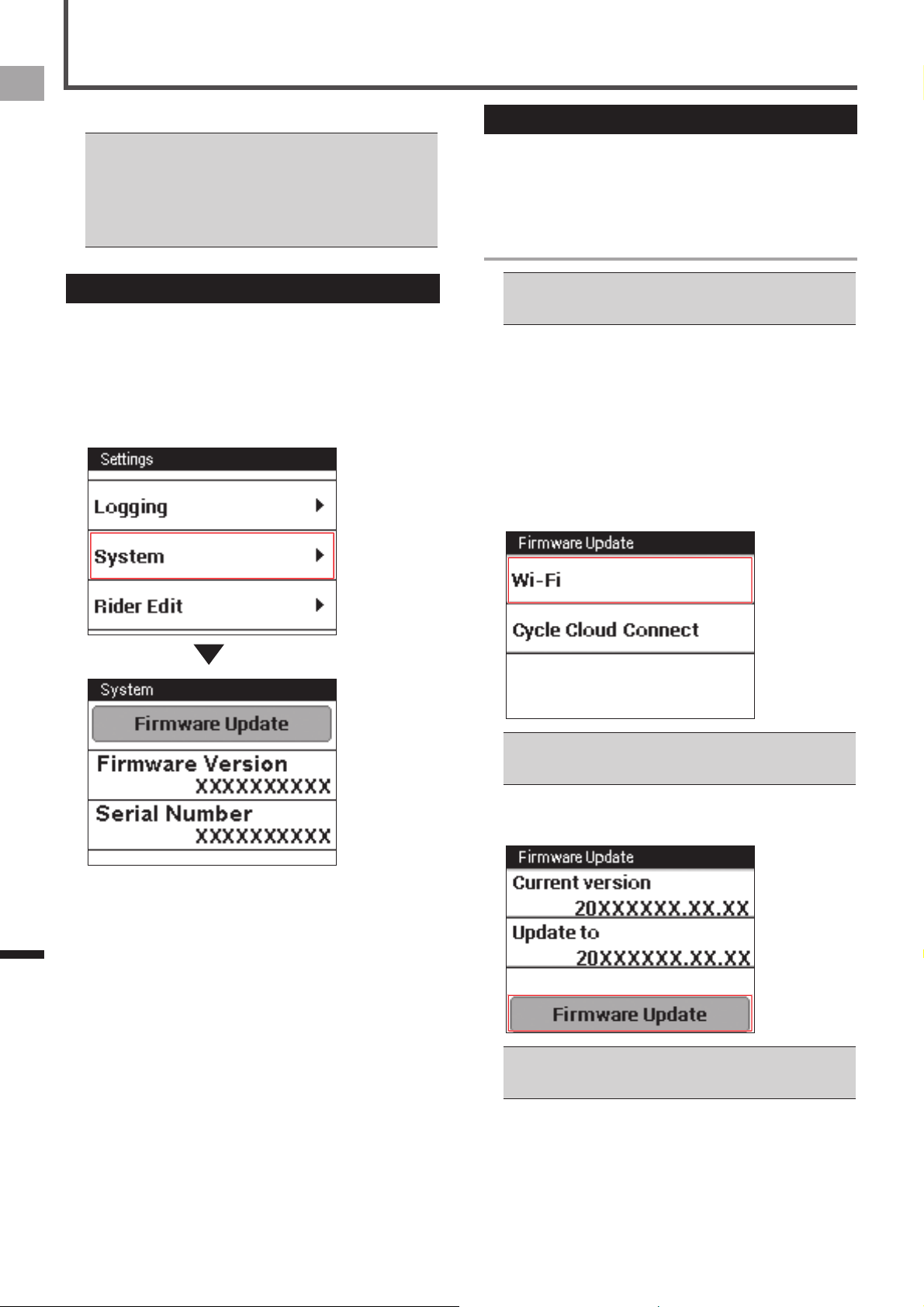
56
EN
Management
Update
Update performs an update of the device's firmware.
Charge the device before the update. If the device is not •
charged fully, the message appears and the update cannot
be performed.
If the device is logging, stop logging and save the log data •
before the update.
When doing a firmware update, backup data is created •
automatically.
Checking the Firmware Version
Before updating the firmware, use the procedure below to
check the device's current firmware version.
1
On the home screen, tap the [Settings] icon.
This displays the settings menu.
2
Tap [System] and then check the number under
[Firmware Version].
Updating the Firmware
You can update the device’s firmware by transferring update
data from the server to the device.
You can update the firmware by connecting the device to
your PC as well as via Wi-Fi.
Updating via Wi-Fi
The device’s Wi-Fi settings must be done to update the •
firmware via Wi-Fi.
«
Wi-Fi Settings (page 44)
1
If the device is connected to the PC with the
USB cable, disconnect it.
2
On the home screen, tap the [Settings] icon.
The settings menu is displayed.
3
Tap [System] – [Firmware Update] – [Wi-Fi].
The Wi-Fi connection starts.
If a Wi-Fi connection is created successfully, the device
starts to connect to the server and checks the firmware
version.
If a Wi-Fi connection is not available, the Wi-Fi settings •
screen is displayed.
«
Wi-Fi Settings (page 44)
4
Check the versions of the firmware to update,
and then tap [Firmware Update].
Tapping [Version Select] displays the versions of the •
firmware to update. Tap [Version Select] and select a
version of the firmware to replace your current version.
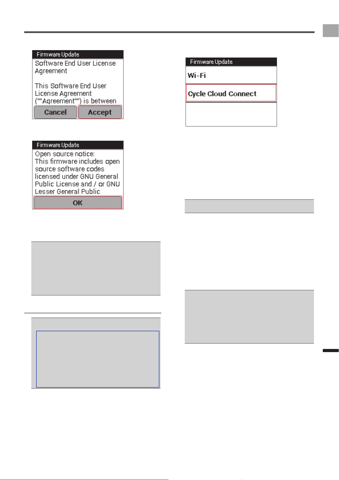
57
EN
Management
Update
5
Confirm the license and tap [Accept].
6
Tap [OK].
The firmware update starts.
The update data is downloaded via Wi-Fi, and the device
restarts.
After completing the firmware update correctly, the
device starts by displaying the logo.
If the battery is not fully charged when updating the •
firmware, a message appears. If this happens, charge the
device. If the remaining battery charge is more than 50%,
the firmware update starts.
If the downloaded firmware data is destroyed or network •
errors occur, a message appears.
If the firmware update is not successful, [FAILURE] is •
displayed on the screen. Press and hold the [START/STOP]
button for 2 seconds or more to turn off the power.
Updating by connecting to a PC
To update the firmware, you need to install the “Pioneer •
Cycle Cloud Connect” application on your PC.
Refer to the support page for instructions on how to install
“Pioneer Cycle Cloud Connect” application to your PC.
[For American Users]
http://www.pioneerelectronics.com
[For Canadian Users (ENGLISH)]
http://www.pioneerelectronics.ca/POCEN/Support
[For Canadian Users (FRENCH)]
http://www.pioneerelectronics.ca/POCFR/Soutien
[For European Users]
http://www.pioneer.eu/eur/support/page.html
1
If the device is connected to the PC with the
USB cable, disconnect it.
2
On the home screen, tap the [Settings] icon.
The settings menu is displayed.
3
Tap [System] – [Firmware Update] – [Cycle
Cloud Connect].
4
Activate “Firmware Manager” of the
CycleCloudConnect from your PC.
For information about activation, refer to the help of the
CycleCloudConnect.
5
Connect the device to your PC.
Use the provided USB cable to connect the device to
your PC.
For information about connections, refer to “Charging the
Device” under “Charging” (
«
page 6).
Do not disconnect the USB cable from your PC until a •
message appears during the update procedure.
6
Check the version of the firmware to update
from CycleCloudConnect and start to update.
The device starts to download the firmware.
After the download is completed, disconnect the USB
cable according to the instructions.
The firmware update starts.
The update data is downloaded from the PC, and the
device restarts.
After completing the firmware update correctly, the
device starts by displaying the logo.
If the battery is not fully charged when updating the •
firmware, a message appears. In this case, charge it. If the
remaining battery charge is more than 50%, the firmware
update starts.
If the downloaded firmware data is destroyed or network •
errors occur, a message appears.
If the firmware update is not successful, [FAILURE] is •
displayed on the screen. Press and hold the [START/STOP]
button for 2 seconds or more to turn off the power.
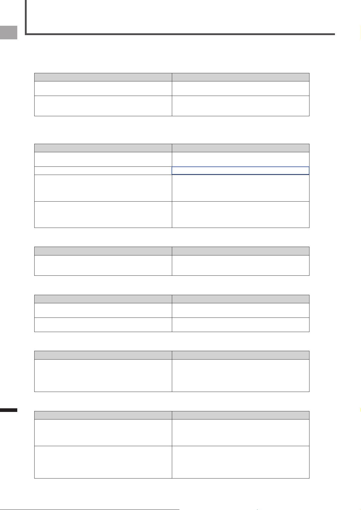
58
EN
Troubleshooting
Troubleshooting
If you have problems with your device, check the following items. If you cannot find a solution to your problem here, contact your
dealer.
Will not power up.
■
Cause Solution
The battery is not charged. Charge the battery.
«
Charging the Device (page 6)
The temperature of the device may be too high or low. Wait until the device is within standard operating temperature
ranges.
«
Charging the Device (page 6)
The battery goes dead soon after it is charged or the message "Shutdown" appears and power turns off
■
when the [START/STOP] button is not pressed.
Cause Solution
The battery charge is low. Charge the battery.
«
Charging the Device (page 6)
The built-in battery is dead. Contact your dealer.
The screen brightness setting is too high. A high screen brightness setting can cause the battery to run
down quickly. To conserve battery power, use a lower screen
brightness setting.
«
Changing Screen Brightness (page 28)
The Wi-Fi connection is turned on. The Wi-Fi connection can cause the battery to run down
quickly. To conserve battery power, turn off the Wi-Fi
connection.
«
Wi-Fi Settings (page 44)
The operation button or the touch panel is not responding.
■
Cause Solution
There are numerous possibilities for non-operation. Push the [START/STOP] button and [LAP] button at the same
time for more than 10 seconds to try the forced reset.
Do not do a forced reset if the device has no malfunction.
The touch panel is not responding.
■
Cause Solution
The touch panel cannot sense your input. The device has a resistive touch panel. Resistive touch
panels require a stronger touch than capacitive touch panels.
The touch panel is locked. Press the [MENU] button to unlock. A message appears when
it unlocks.
You do not know how to initialize.
■
Cause Solution
- Tap [Settings]-[System]-[Setting Manager]-[Initialize] from the
home screen to initialize.
«
Initialize (page 53)
If you initialize, the ride log data will be deleted. Save the data
to a PC before initialization.
Sensor information is not displayed.
■
Cause Solution
The sensor is not paired. Check that the sensor is paired to the device properly. If you
use the pedaling monitor sensor SGY-PM910H/PM900H,
refer to the User’s Manual of the SGY-PM910H/PM900H and
Installation Manual.
The sensor battery is almost empty.
Or the battery is not loaded in the sensor correctly.
Replace the battery with a new one.
Or check to make sure that the battery is correctly loaded in
the sensor.
For details about how to replace and load the sensor battery,
refer to the sensor user's manuals.
59
EN
Troubleshooting
Troubleshooting
Cannot pair sensors with the device.
■
Cause Solution
Multiple sensors are activated. Bring the device closer to the sensor you want to pair with or
specify the sensor device number and then try pairing.
«
Pairing Sensors (page 13)
The battery of the sensor is almost empty.
Or the battery is not loaded in the sensor correctly.
Replace the battery with a new one.
Or check to make sure that the battery is correctly loaded in
the sensor.
For details about how to replace and load the sensor battery,
refer to the sensor user's manuals.
The latitude and longitude are not displayed.
■
Cause Solution
Reception is poor when inside a room or in areas surrounded
by mountains or tall buildings.
It may take a few minutes to display the latitude and longitude
when you use the device the first time.
Use the device outside in an open area.
When you use the device for the first time, you may need to
allow extra time.
The Cyclocomputer is not recognized when connected to a PC.
■
Cause Solution
The Cyclocomputer is not connected correctly to the PC. Unplug the USB cable from the device and PC and restart the
device. After that, try connecting to the PC with the USB cable
again.
Response is different from the location touched on the touch panel.
■
Cause Solution
The touch panel is not calibrated correctly. Recalibrate the touch panel.
«
Calibrating the Touch Panel (page 47)
GPS information is not received correctly.
■
Cause Solution
Nearby tall buildings or trees are blocking communication. Move away from the tall buildings or trees, wait for a few
minutes, and try again.

60
EN
Troubleshooting
About Error Messages
Message Cause Solution
Charging impossible You tried to charge the battery outside the
charging temperature range of 0 °C to 45 °C. You
cannot charge the battery outside the charging
temperature range of 0 °C to 45 °C for safety
reasons. The device may not have charged even
though the outside temperature is below 45 °C.
This happens because the device heats up when
the battery is charging.
Charge the battery in the charging temperature
range of 0 °C to 45 °C. If you turn off the device
when the battery is charging, the temperature does
not rise (
«
page 6).
The device stops charging when although it is not
charged enough even after a certain specified
charging time has passed.
This may happen because you charge the battery
while using Wi-Fi on the device with power on,
which causes to decrease the charging current.
Turn off the device’s Wi-Fi (
«
page 44).
Failed to start USB mass storage.
Disconnect, wait 5 minutes, reconnect
USB connection failed. This message also appears
when the mass storage connection is not available
and the USB is connected such as during the
setting backup.
Unplug the USB cable from the device, wait for a
while, and then try connecting again.
Storage space is getting low.
Please remove unnecessary data.
There is not enough free memory in the device
system area.
Transfer the ride log data to a PC. Delete the data
in the built-in flash memory from the PC (
«
page
26).
Please remove unnecessary data. There is not enough free memory in the built-in
flash memory of the device. This message appears
when the update data is stored temporarily to the
built-in flash memory during the update procedure.
Transfer the ride log data to a PC. Delete the data
in the built-in flash memory from the PC (
«
page
26).
Battery level is low. Please connect
power supply.
Updating will start after fully charged.
The device can be updated only when it is fully
charged to prevent update failures.
Charge the battery of the device. When charged
fully, the device starts updating automatically.
Shutdown If the remaining battery is low, this message is
displayed before shutdown.
Not while charging : Charge the battery •
While charging : Continue charging the battery•
Battery Level Decreasing If the remaining battery is low, this message is
displayed 5 minutes before shutdown.
Not while charging : Charge the battery•
While charging : Turn off the power and continue •
charging the battery.
Detected data is inconsistent. Do you
want to try again?
There is a failure in touch panel calibration data.
For example you didn't touch the plus mark during
the touch panel calibration.
Tap the center of the plus mark during the touch
panel calibration.
Built-in flash memory error There is a failure in file system of built-in flash
memory when you execute the initialization,
backup, or restore.
Format the built-in flash memory.
File Error CODE:0001 There is a file access error when you execute the
initialization, backup, or restore.
If errors occur during the initialization, try to write •
the firmware again. If you still cannot solve the
problem, contact your dealer.
If errors occur during the backup, transfer the •
ride log data and backup data to a PC, and then
remove them from the built-in flash memory.
Remove the unnecessary files in the built-in
flash memory.
If errors occur during the restore, copy other
•
backup data from the PC to the device to restore
the data.
The system try to mount the file system when you
execute the initialization, backup, or restore. If the
system can't confirm the mount, this message is
displayed.
Format the built-in flash memory.•
Retry to write the firmware.•
If you cannot solve the problem, contact your •
dealer.
When the initialization, backup, or restore times
out, this message is displayed.
Format the built-in flash memory.•
Retry to write the firmware.•
If you still cannot solve the problem, contact your •
dealer.
The built-in flash memory format failed. When the built-in flash memory format failed, this
message is displayed.
If the logging, timer reset, or setting manager
(initializing, backup, or restore) is in progress, retry
the memory format after finishing each command.
In the other cases, wait for a while, and then retry
to format the memory.
Storage space is getting low. If the remaining memory in the system area is
less than 100MB, this message is displayed every
minute.
Reset the ride log data.
Range of the valid value is XXX - YYY When you input the value outside a setting range,
this message is displayed.
Input the value within a setting range.

61
EN
Appendix
Care, Maintenance, and Storage
Make sure that the power of the device is turned off before
cleaning.
Use a commercial cleaning cloth to clean the display.•
Use a soft dry cloth or a cloth that has been dampened •
and wrung out to wipe the device or the bracket.
Do not use benzene, paint thinner, or other volatile •
chemicals, cleansers, or chemically treated cloths. Doing
so could damage the product or cause the paint to peel.
Discharge the battery and store the device in a cool and •
dark place if being stored for a long period of time.
Removing the Battery
Remove the lithium-ion battery by the following procedures
to dispose of the device.
Please use caution when removing the battery. Please •
never attempt to disassemble the device except when you
dispose of the battery.
1.
Remove the screw of the USB connector cover.
Please be careful not to damage the groove on the screw •
head when removing the screws of the USB connector
cover.
2.
Remove the screw of the device.
Use a Phillips-head screwdriver and remove the screws
(4) from the back of the device.
3.
Remove the back cover of the device and the
lithium-ion battery cable from the substrate.
When removing the lithium-ion battery cable, please hold •
and pull the connector without pulling the cable part. Pulling
the cable may cause a disconnection.
4.
Remove the lithium-ion battery from the back
cover.
Remove the tape that holds the lithium-ion battery to
remove the battery.
Be careful not to damage the lithium-ion battery.
[For American Users, Canadian Users]
Follow applicable laws and regulations for transport,
shipping, and disposal of batteries. For details on recycling
the lithium-ion battery, please contact a government recycling
agency, your waste-disposal service, or visit reputable online
recycling sources such as www.batteryrecycling.com
[Pour les utilisateurs américains, utilisateurs canadiens]
Respectez les législations et réglementations en vigueur
concernant le transport, l’expédition et l’élimination des
batteries. Pour plus de détails concernant le recyclage
des batteries lithium-ion, veuillez contacter une agence
gouvernementale dédiée au recyclage, votre service
d’élimination des déchêts ou visitez les sources de recyclage
en ligne reconnues telles que www.batteryrecycling.com

62
EN
Appendix
Specifications
Weight: About 75 g
Dimensions: 58 mm (W) x 58 mm (H) x 19 mm (D) (without projection parts)
Connector: microUSB
Water resistant: This device has a water resistance rating of IPX-6/IPX-7.
Communications method (sensors): ANT+ wireless
Communications method (network): Wi-Fi
Positioning system (latitude, longitude): GPS
Positioning system (altitude): Air pressure sensor
Display: 160x128 pixel, horizontal 1.87 inch outdoor type, Black and white
Touch panel (resistive touch display)
Built-in flash memory: 4 GB (user available capacity 3 GB)
Operation temperature: −10 °C to 50 °C
Charging temperature: 0 to 45°C
Power requirement: DC 5V
Battery type: Lithium-ion battery
Battery operating time: Approximately 12 hours
Charging time: Approximately 4 hours (Power off or normal charging)
Approximately 3 hours (Power off or boost charging)
The battery operating time may decrease depending on the operating conditions.•
ANT+ is a wireless personal network protocol with very low power requirements using the 2.4 GHz frequency band.•
For more information, visit http://www.thisisant.com/
Specifications and design are subject to possible modifications without notice due to improvements.•
Illustrations used in this manual may be different from the actual device.•

63
EN

©2014 PIONEER CORPORATION.
All rights reserved.
<2014/3 A> EU
http://www.pioneerelectronics.com
http://www.pioneerelectronics.ca
http://www.pioneer.eu
Visit www.pioneer.eu to register your product.
Visitez www.pioneer.eu pour enregistrer votre appareil.
Si prega di visitare il sito www.pioneer.eu per registrate il prodotto.
Visite www.pioneer.eu para registrar su producto.
Zum Registrieren Ihres Produktes besuchen Sie bitte www.pioneer.eu.
Bezoek www.pioneer.eu om uw product te registreren.
PIONEER CORPORATION
1-1, Shin-ogura, Saiwai-ku, Kawasaki-shi, Kanagawa 212-0031, JAPAN
PIONEER ELECTRONICS (USA) INC.
P.O. Box 1540, Long Beach, California, 90801-1540, U.S.A.
TEL: (800) 421-1404
PIONEER ELECTRONICS OF CANADA INC.
340 Ferrier Street, Unit 2, Markham, Ontario, L3R 2Z5, Canada
TEL: 1-877-283-5901
TEL: 905-479-4411
PIONEER EUROPE NV
Haven 1087, Keetberglaan 1, B-9120 Melsele, Belgium/Belgique
TEL: +32 (0)3 570 05 11