

Welcome
Congratulations on your purchase of a new
Honda vehicle. Your selection of a Honda
makes you part of a worldwide family of
satisfied customers who appreciate Honda's
reputation for building quality into every
product.
To ensure your safety and riding pleasure:
● Read this owner's manual carefully.
● Follow all recommendations and
procedures contained in this manual.
● Pay close attention to safety messages
contained in this manual and on the
vehicle.
To protect your investment, we urge you to
take responsibility for keeping your vehicle
well serviced and maintained. Also, observe
the break-in guidelines, and always perform
the pre-ride inspection and other periodic
checks in this manual.
When service is required, remember that
your Honda dealer knows your vehicle best.
If you have the required mechanical “know-
how” and tools, you can purchase an official
Honda Service Manual to help you perform
many maintenance and repair tasks. 2 P. 168
Read the warranty information thoroughly so
that you understand the warranty coverage
and that you are aware of your rights and
responsibilities. 2 P. 169
You may also want to visit our website at
www.powersports.honda.com.
Canada
www.honda.ca.
Happy riding!
A Few Words About Safety
Your safety, and the safety of others, is very
important. Operating this vehicle safely is an
important responsibility.
To help you make informed decisions about
safety, we have provided operating
procedures and other information on safety
labels and in this manual. This information
alerts you to potential hazards that could
hurt you or others.
Of course, it is not practical or possible to
warn you about all hazards associated with
operating or maintaining a vehicle. You must
use your own good judgment.
You will find important safety information in a
variety of forms, including:
● Safety labels on the vehicle
●
Safety Messages preceded by a safety alert
symbol and one of three signal words:
DANGER, WARNING, or CAUTION.
These signal words mean:
3DANGER
You WILL be KILLED or SERIOUSLY
HURT if you don’t follow instructions.
3WARNING
You CAN be KILLED or SERIOUSLY
HURT if you don’t follow instructions.
3CAUTION
You CAN be HURT if you don’t follow
instructions.
Other important information is
provided under the following titles:
NOTICE
Information to help you avoid
damage to your vehicle, other
property, or the environment.

Safety Guidelines................................................. P. 3
Safety Labels.......................................................
.. P. 8
Safety Precautions............................................. P. 10
Riding Precautions ............................................ P. 11
Accessories & Modifications........................... P. 16
Loading ................................................................ P. 17
This section contains important information for safe riding of your vehicle.
Please read this section carefully.
Vehicle Safety

Safety Guidelines
Follow these guidelines to enhance your safety:
● Perform all routine and regular inspections
specified in this manual.
● Stop the engine and keep sparks and flame
away before filling the fuel tank.
● Do not run the engine in enclosed or partly
enclosed areas. Carbon monoxide in
exhaust gases is toxic and can kill you.
Always Wear a Helmet
It's a proven fact: helmets and protective
apparel significantly reduce the number and
severity of head and other injuries. So always
wear an approved helmet and protective
apparel. 2 P. 10
Before Riding
Make sure that you are physically fit, mentally
focused and free of alcohol and drugs. Check
that you and your passenger are both wearing
an approved helmet and protective apparel.
Instruct your passenger on holding onto the
grab rails or your waist, leaning with you in
turns, and keeping their feet on the footpegs,
even when the vehicle is stopped.
Safety Guidelines
Vehicle Safety
3
Continued

If You are Involved in a Crash
Personal safety is your first priority. If you or
anyone else has been injured, take time to
assess the severity of the injuries and whether it
is safe to continue riding. Call for emergency
assistance if needed. Also follow applicable laws
and regulations if another person or vehicle is
involved in the crash.
If you decide to continue riding, first turn the
ignition switch to the OFF position, and evaluate
the condition of your vehicle. Inspect for fluid
leaks, check the tightness of critical nuts and
bolts, and check the handlebar, control levers,
brakes, and wheels. Ride slowly and cautiously.
Your vehicle may have suffered damage that is
not immediately apparent. Have your vehicle
thoroughly checked at a qualified service facility
as soon as possible.
Emergency Shut-down Procedure for
Vehicles Equipped with Dual Clutch
Transmission
NC750XD
Unlike standard vehicles, or its manual
transmission sibling, the NC750XD with dual-
clutch transmission does not have a clutch lever
that would provide you with an additional
means to control the engine power being
transmitted to the rear wheel. Thus, in the
unlikely event that you experience a stuck
throttle or other unintended application of
power to the rear wheel, you should shut down
the engine by use of the engine stop switch
(2 P. 53). By moving this switch to the
(Stop)
position, you will immediately stop the engine
but maintain all electrical system functions,
including lights and indicators.
Safety Guidelines
Vehicle Safety
6
Carbon Monoxide Hazard
Exhaust contains poisonous carbon monoxide, a
colorless, odorless gas. Breathing carbon
monoxide can cause loss of consciousness and
may lead to death.
If you run the engine in confined or even partly
enclosed area, the air you breathe could
contain a dangerous amount of carbon
monoxide.
Never run your vehicle inside a garage or other
enclosure.
3WARNING
Running the engine of your vehicle
while in an enclosed or even partially
enclosed area can cause a rapid build-
up of toxic carbon monoxide gas.
Breathing this colorless, odorless gas
can quickly cause unconsciousness and
lead to death.
Only run your vehicle's engine when it
is located in a well ventilated area
outdoors.
Safety Guidelines
Vehicle Safety
7

● Exercise caution on low traction surfaces.
u The tires slip more easily on such
surfaces and braking distances are
longer.
● Avoid continuous braking.
u Repeated braking, such as when
descending long, steep slopes can
seriously overheat the brakes, reducing
their effectiveness. Use engine braking
with intermittent use of the brakes to
reduce speed.
● For full braking effectiveness, operate both
the front and rear brakes together.
#
Anti-lock Brake System (ABS)
NC750XA/XD
This model is equipped with an Anti-lock Brake
System (ABS) designed to help prevent the
brakes from locking up during hard braking.
● ABS does not reduce braking distance. In
certain circumstances, ABS may result in a
longer stopping distance.
● ABS does not function at speeds below
6 mph (10 km/h).
● The brake lever and pedal may recoil slightly
when applying the brakes. This is normal.
● Always use the recommended front/rear
tires and sprockets to ensure correct ABS
operation.
Riding Precautions
Vehicle Safety
12

#
Engine Braking
Engine braking helps slow your vehicle down
when you release the throttle. For further
slowing action, downshift to a lower gear. Use
engine braking with intermittent use of the
brakes to reduce speed when descending long,
steep slopes.
#
Wet or Rainy Conditions
Road surfaces are slippery when wet, and wet
brakes further reduce braking efficiency.
Exercise extra caution when braking in wet
conditions.
If the brakes get wet, apply the brakes while
riding at low speed to help them dry.
Parking
● Park on a firm, level surface.
● If you must park on a slight incline or loose
surface, park so that the vehicle cannot
move or fall over.
● Make sure that high-temperature parts
cannot come into contact with flammable
materials.
● Do not touch the engine, muffler, brakes
and other high-temperature parts until they
cool down.
● To reduce the likelihood of theft, always lock
the handlebar and remove the key when
leaving the vehicle unattended.
Use of an anti-theft device is also
recommended.
#
Parking with the Side Stand
1.
Stop the engine.
2.
Push the side stand down.
Riding Precautions
Vehicle Safety
13
Continued

3.
Slowly lean the vehicle to the left until its
weight rests on the side stand.
4.
Turn the handlebar fully to the left.
u Turning the handlebar to the right
reduces stability and may cause the
vehicle to fall.
5.
Turn the ignition switch to the LOCK
position and remove the key. 2 P. 54
Refueling and Fuel Guidelines
Follow these guidelines to protect the engine,
fuel system and catalytic converter:
● Use only unleaded gasoline.
● Use recommended octane number. Using
lower octane gasoline will result in
decreased engine performance.
● Do not use fuels containing a high
concentration of alcohol. 2 P. 167
● Do not use stale or contaminated gasoline
or an oil/gasoline mixture.
● Avoid getting dirt or water in the fuel tank.
Riding Precautions
Vehicle Safety
14

Honda selectable torque control
NC750XA/XD
When the Honda selectable torque control
(Torque Control) detects rear wheel spin during
acceleration, the system will limit the amount of
torque applied to the rear wheel based on the
Torque Control level selected.
Torque Control will allow some wheel spin
during acceleration at the lower Torque Control
levels settings. Select a level that is appropriate
for your skill and riding conditions.
Torque Control does not work during
deceleration and will not prevent the rear wheel
from skidding due to engine braking. Do not
close the throttle suddenly, especially when
riding on slippery surfaces.
Torque Control may not compensate for rough
road conditions or rapid throttle operation.
Always consider road and weather conditions,
as well as your skills and condition, when
applying throttle.
If your vehicle gets stuck in mud, snow or sand,
it may be easier to free it by turning off the
Torque Control temporarily.
Temporarily turning off Torque Control also
may help you maintain control and balance
when riding on off-road terrain.
Always use the recommended tires and
sprockets to ensure correct Torque Control
operation.
Riding Precautions
Vehicle Safety
15

Accessories &
Modifications
We strongly advise that you do not add any
accessories that were not specifically designed
or approved for your vehicle by Honda or make
modifications to your vehicle from its original
design. Doing so can make it unsafe.
Modifying your vehicle may also void your
warranty and make your vehicle illegal to
operate on public roads. Before deciding to
install accessories on your vehicle be certain the
modification is safe and legal.
3WARNING
Improper accessories or modifications
can cause a crash in which you can be
seriously hurt or killed.
Follow all instructions in this owner's
manual regarding accessories and
modifications.
Do not pull a trailer with, or attach a sidecar to,
your vehicle. Your vehicle was not designed for
these attachments, and their use can seriously
impair your vehicle's handling.
Accessories & Modifications
Vehicle Safety
16

Loading
● Carrying extra weight affects your vehicle's
handling, braking and stability.
Always ride at a safe speed for the load you
are carrying.
● Avoid carrying an excessive load and keep
within specified load limits.
Maximum weight capacity / Maximum
weight in luggage box / on luggage
box lid 2 P. 174
● Tie all luggage securely, evenly balanced
and close to the center of the vehicle.
● Do not place objects near the lights or the
muffler.
3WARNING
Overloading or improper loading can
cause a crash and you can be seriously
hurt or killed.
Follow all load limits and other loading
guidelines in this manual.
Loading
Vehicle Safety
17
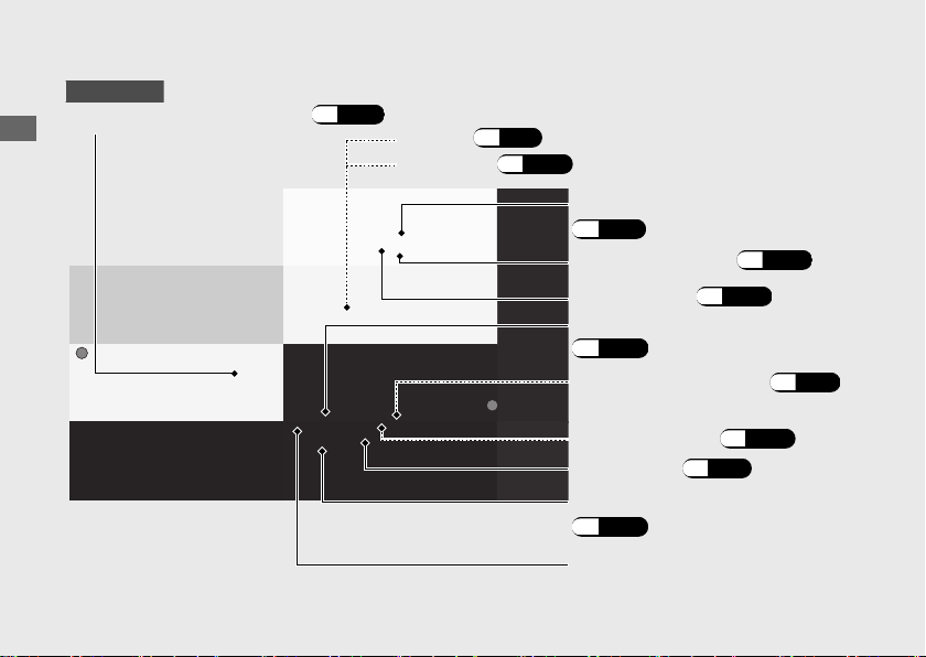
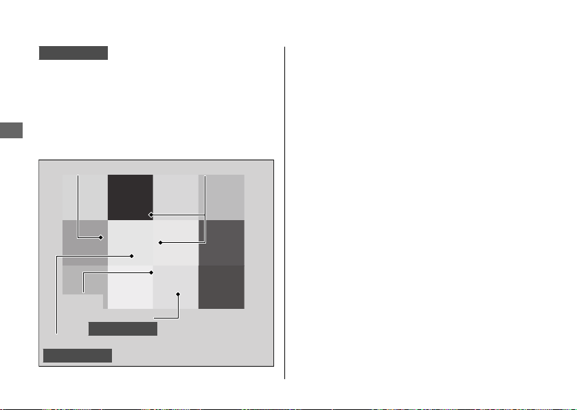
Parts Location
Operation Guide
18
Front brake lever
(P.128)
Main fuse (P.150)
Battery
(P.97)
Coolant reserve tank (P.111)
Rear brake fluid reservoir
(P.113)
Rear brake pedal
Engine oil filter (P.107)
Engine oil fill cap/dipstick
(P.105)
Engine oil drain bolt
(P.107)
Throttle grip (P.124)
Front brake fluid reservoir
(P.113)
Lower cowl (P.99)
NC750X/XA
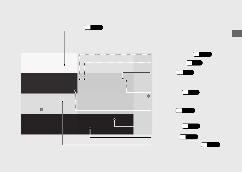

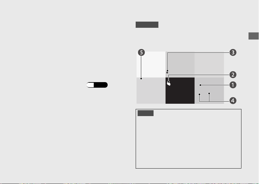
Instruments
Operation Guide
22
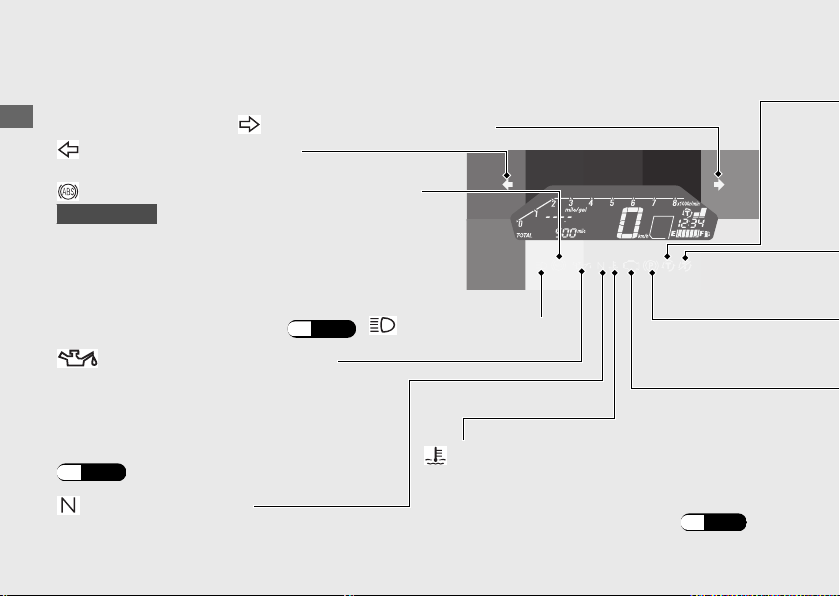
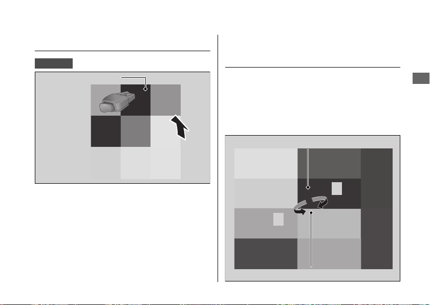
SET buttonTotal area
Display Check
All the modes and digital segments will show when the ignition switch is turned to the ON
position. If any part of these displays does not come on when it should, have your dealer
check for problems.
SEL button
u
NC750X
If the opening/ending display is being set to SP, letters which have been set are displayed in
the total area. To check the display in the total area, set the opening/ending display to STD.
(P.36)
Operation Guide
23
Continued
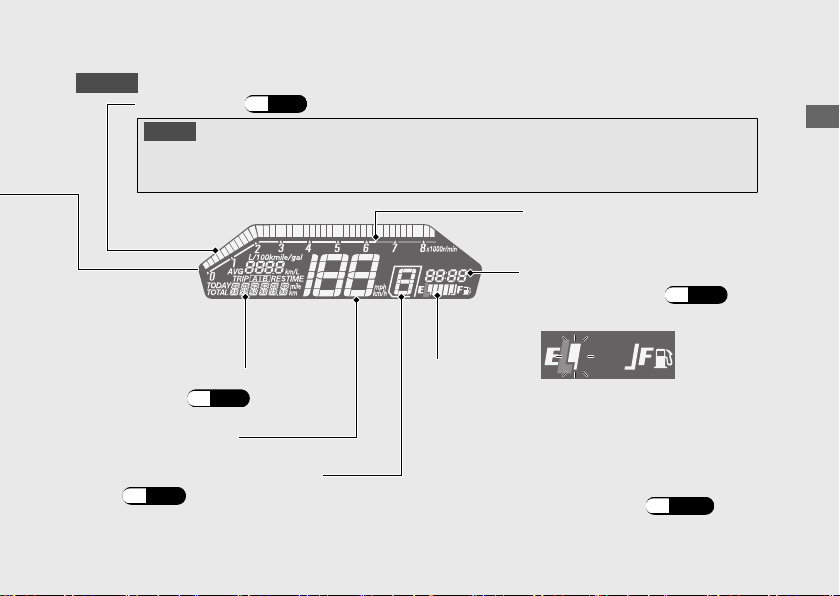
NC750X
NOTICE
Do not operate the engine in the tachometer red zone. Excessive engine speed can
adversely affect engine life.
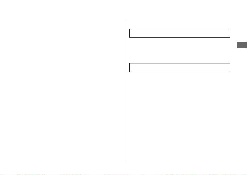
Tachometer
(P.30)
(excessive engine rpm range)
Tachometer red zone
Speedometer
Total/Fuel mileage
display (P.25)
Gear position indicator
(P.35)
Fuel gauge
Remaining fuel when only 1st (E) segment starts
flashing: approximately
0.85 US gal (3.2 L)
The reserve tripmeter display and reserve fuel
consumption display show at the same time.
If the fuel gauge indicator flashes in a
repeat pattern or turns off:
(P.136)
Clock
To set the clock: (P.36)

#
Reserve tripmeter (only when reserve fuel mode)
Distance ridden since the 1st (E) segment of the fuel gauge and “RES” start
flashing.
The “RES” will flash faster when the fuel decreases further.
When the fuel gauge is near the 1st (E) segment or flashes, fill fuel promptly.
When “----.-” is displayed, go to your dealer for service.
#
Reserve fuel consumption (only when reserve fuel mode)
Fuel consumption since the 1st (E) segment of the fuel gauge and “RES” start flashing.
The “RES” will flash faster when the fuel decreases further.
When the fuel gauge is near the 1st (E) segment or flashes, fill fuel promptly.
When “---.-” is displayed, go to your dealer for service.
Operation Guide
28
Instruments (Continued)

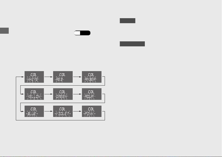
ECO mode
Depending on the fuel consumption, the tachometer segment color will change.
If the fuel consumption is improved, the color of the tachometer will change to AQUA.
Further, when the fuel consumption is improved, it will turn GREEN.
u The
ECO mode color is not displayed at speeds below approximately 12 mph (20 km/h).
u When the gear position mode or engine rev mode in the base color mode is selected, the ECO
mode color is not displayed even if the ECO mode is set to on.
To set the
ECO mode:
(P.36)
Shift up mode
When the number of engine revolution reaches shift-up point you have set, the color of the
tachometer shows in AMBER this informs you of the indication to shift up.
Default setting is “5,000 rpm”.
u When the gear position mode or engine rev mode in the base color mode is selected, the shift-
up mode color is not displayed even if the shift up mode is set to on.
To set the shift up mode: (P.36)
To set the shift up point: (P.36)
Operation Guide
33
Continued

Opening/Ending display
NC750X
You can select the meter display when turning the ignition switch on or off from the STD mode
and SP mode.
If you select the SP mode, the letters you want to show can also be displayed while the
opening/ending display is shown.
To set the opening/ending display:
(P.36)
To set the opening/ending message: (P.36)
NC750XA/XD
When the ignition switch is turned On or Off, the letters you want to show can also be
displayed while the opening/ending display is shown.
To set the opening/ending message:
(P.36)
Operation Guide
34
Instruments (Continued)

Gear position indicator
NC750X/XA
The gear position is shown in the gear position indicator.
u “-” flashes when the ignition switch is turned to the ON position with the engine stop switch
(Stop) position.
u “-” appears when the transmission is not shifted properly.
NC750XD
The gear position is shown in the gear position indicator when the D, S mode or MT MODE are
selected.
u “-” appears for a few seconds and then goes off when the engine starts.
u “-” flashes when the engine stop switch position is changed from
(Run) to (Stop) position
with the ignition switch in the ON position.
u “-” flashes when the ignition switch is turned to the ON position with the engine stop switch
(Stop) position.
The indicator may flash if:
u The front wheel leaves the ground.
u You turn the wheel while the vehicle is upright on the stand.
This is normal. To operate the system again, turn the ignition switch to the OFF position, then
to the
ON position again.
If the “-” indicator is blinking in the gear position window while riding:
(P.135)
Operation Guide
35
Continued

Selecting the setting mode:
a
Turn the ignition switch to the ON position.
b
Press and hold the SEL button and SET
button until the ON/OFF setting display
changes.
c
Press the SEL button until the desired setting
mode is displayed. When the SEL button is
pressed, the setting mode will be changed.
d
When the SET button is pressed, each
setting mode will be changed.
To return to the ordinary display from the
setting mode:
● The SEL button and/or SET
button is not
pressed for about 30 seconds.
● Turn the ignition switch to the OFF
position, and then to the ON position.
● Press and hold SEL button and
SET
button.
While operating settings, each setting will be
cancelled if the SET
button is not pressed.
Operation Guide
37
Continued
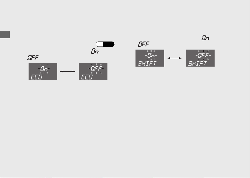
ON/OFF Setting Mode
1 ECO mode setting:
You can set on or off of the ECO mode.
a
Select the
ON/OFF setting mode.
(P.36)
b
Press the
SEL button to select “
” or
“ ”.
c
Press the SET button. The ECO mode is set,
and the display moves to the shift up mode
setting.
u When the tachometer segment color is
set to GREEN or AQUA and the ECO
mode is set to on, the user setting color
will automatically change to WHITE.
2 Shift up mode setting:
You can set on or off of the shift up mode.
a
Press the SEL button to select “ ” or
“ ”.
b
Press the SET button. The shift up mode is
set.
u When the tachometer segment color is
set to AMBER and the shift up mode is
set to on, the user setting color will
automatically change to WHITE.
u When the shift up mode is set to on, the
display moves to the shift up point
adjustment.
u When the shift up mode is set to off, the
display moves to the activating/
deactivating of tripmeter A, average fuel
mileage and fuel consumption automatic
reset mode.
Operation Guide
38
Instruments (Continued)

4 Activating/deactivating of tripmeter
A, average fuel mileage and fuel
consumption automatic reset mode:
You can also activate or deactivate the
automatic reset mode by refueling after 1st
(E) segment of the fuel gauge start flashing.
Deactivation is initially set.
a
Press the SEL button to select “ ”
(activate) or “ ” (deactivate) in the
automatic reset mode.
b
Press SET button. The activation/
deactivation of automatic reset mode is set,
and the display returns to the ordinary
display.
ADJ Setting Mode
1 Clock (12/24-hour) setting:
a
Select the ADJ setting mode. (P.36)
b
Press the
SEL button to select "12HOUR" or
"24HOUR".
c
Press the SET button. The clock 12/24 - hour
is set, and the display moves to the
changing of the clock setting.
Operation Guide
40
Instruments (Continued)

2 Clock setting:
a
Press the SEL button until the desired hour is
displayed.
u When the 12HOUR display is set, the
AM/PM is displayed. The display changes
from 11 to 12, it will switch at the same
time.
u Press and hold the SEL button to
advance the hour fast.
b
Press the SET button. The minute digits start
flashing.
c
Press the SEL button until the desired
minute is displayed.
u Press and hold the SEL button to
advance the minute fast.
d
Press the SET button. The clock is set, and
the display moves to the backlight
brightness H (high) adjustment.
Operation Guide
41
Continued
SP Setting Mode
1 Selecting the user setting mode color:
a
Select the SP setting mode. (P.36)
b
Press the SEL
button. The color is switched.
u When the ECO mode is set to on, AQUA
and GREEN can not be selected.
u When the shift up mode is set to on,
AMBER can not be selected.
c
NC750X
Press the SET button. The user setting mode
color is set, and the display moves to the
opening/ending display setting.
NC750XA/XD
Press the SET button. The user setting mode
color is set, and the display moves to the
inputting the opening message.
Operation Guide
44
Instruments (Continued)

2 Opening/ending display setting:
NC750X
You can set the STD or SP opening/ending
display.
a
Press the SEL button to select “STD” or “SP”.
b
Press the SET button. The opening/ending
display is set.
u When STD is set, the display returns to
ordinary display.
u When SP is set, the display moves to the
inputting the opening message.
3 Inputting the opening message:
Opening message can input 6 letters for
each 3 lines.
a
Press the SEL button until the desired letter
is displayed.
u You can input the alphabetical letters,
numbers and symbols. (P.46)
u Press and hold the SEL button to
advance the letter fast.
u The line number which is inputting the
letters is displayed in the mileage area.
b
Press the SET button. The letter is set, and
the next letter will start flashing.
Follow the procedure step 1 and 2 until
the end of line 3 letter is set.
Then the display moves to the inputting
the ending message.
Operation Guide
45
Continued
Line number

4 Inputting the ending message:
Ending message can input 6 letters for each
3 lines.
Ending message can be input in the same
manner as opening message.
After the ending message has been set, and
the display returns to the ordinary display.
Selecting letters at the opening/ending
display:
When the SEL button is pressed, the letters
are displayed in the following order.
Operation Guide
46
Instruments (Continued)
(Space)
A B C D E F G H I J
K L M N O P Q SR T
U V W YX Z
1 2 3 4 5 6 7 8 90
! # $ % & ‘ ' ( )
“
*
+
, - . / : ;
< >
=
?
@ ^
_
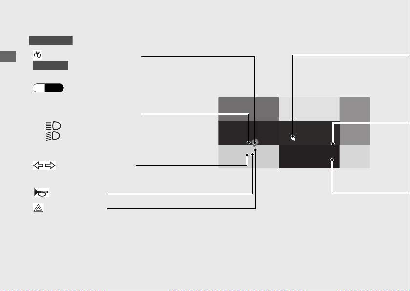
Indicators
Operation Guide
48
If one of these indicators does not come on when it should, have your dealer
check for problems.
Neutral indicator
Comes on when the transmission is in Neutral.
Left turn signal indicator
High coolant temperature indicator
Comes on when the ignition switch is
turned to the ON position.
If it comes on while riding: (P.131)
Low oil pressure indicator
Comes on when the ignition switch is turned
to the ON position.
Goes off when the engine starts.
If it comes on while engine is running:
(P.132)
High beam indicator
ABS (Anti-lock Brake System) indicator
NC750XA/XD
Comes on when the ignition switch is turned to
the ON position.
Goes off when your speed reaches
approximately 6 mph (10 km/h).
If it comes on while riding:
(P.133)
Right turn signal indicator
Switches
Operation Guide
50
u Pressing the switch turns the turn signal off.
Turn signal switch
Horn button
Hazard switch
Switchable when the ignition switch is in the ON position.
Can be turned to off regardless of the ignition switch position.
u The signals continue flashing with the ignition switch is in
the OFF or LOCK position after the hazard switch is on.
Headlight dimmer switch
• : High beam
• : Low beam
Torque Control switch
NC750XA
Torque Control level setting and Torque Control on/off.
(P.56)
NC750X/XA

Operation Guide
52
Switches (Continued)
Hazard switch (P.50)
Shift up switch (
+)
To shift up the gear.
(P.68)
Headlight dimmer
Turn signal switch
Shift down switch (−)
To shift down the gear. (P.68)
● : High beam
● : Low beam
u Pressing the switch turns the turn signal off.
Horn button
Torque Control switch
Torque Control level setting and
Torque Control on/off. (P.56)
NC750XD
Parking Brake
Parking brake lever and Release button
NC750XD
Be sure the parking brake is applied while
parking and warming up the engine.
u Make sure the parking brake lever is
released before riding.
#
Locking
Pull the parking brake lever (a) back to lock
the rear wheel.
u Be sure the release button pops out and
parking brake lever is not released.
u The parking brake lock will not function if
the parking brake is not adjusted properly.
(P.115)
#
Unlocking
Release the parking brake lever by lightly
pulling in the lever (a) and pressing the
release button (b).
u Before riding, check that the parking brake
indicator is turned off and make sure that
the parking brake is fully released so there is
no drag on the rear wheel.
Operation Guide
55
b
a
Parking brake lever
Release button

Operation Guide
57
Level 2
Off
Press the Torque Control switch
Press and hold the Torque Control switch
Level 1
Torque Control
level: maximum
Torque Control
level: minimum
No Torque
Control
If the engine does not start:
a
Open the throttle fully and press the start
button for 5 seconds.
b
Repeat the normal starting procedure.
c
If the engine starts, open the throttle slightly
if idling is unstable.
d
If the engine does not start, wait 10 seconds
before trying steps a & b again.
#
If Engine Will Not Start
(P.130)
NC750XD
Start your engine using the following
procedure, regardless of whether the engine
is cold or warm.
NOTICE
•
If the engine does not start within 5 seconds, turn the
ignition switch to the OFF position and wait 10 seconds
before trying to start the engine again to recover
battery voltage.
•
Extended fast idling and revving the engine can
damage the engine, and the exhaust system.
•
Snapping the throttle or fast idling for more than about
5 minutes may cause exhaust pipe discoloration.
Operation Guide
59
Continued

Shifting Gears
NC750X/XA
Your vehicle transmission has 6 forward
gears in a one-down, five-up shift pattern.
If you put the vehicle in gear with the side
stand down, the engine will shut off.
#
Recommended Shift Points
Shifting Up
From 1st to 2nd 12 mph (20 km/h)
From 2nd to 3rd 19 mph (30 km/h)
From 3rd to 4th 25 mph (40 km/h)
From 4th to 5th 31 mph (50 km/h)
From 5th to 6th 37 mph (60 km/h)
Shifting Down
From 6th to 5th 28 mph (45 km/h)
From 5th to 4th 22 mph (35 km/h)
From 4th to 3rd 16 mph (25 km/h)
NOTICE
Improper shifting can damage the engine, transmission, and
drive train. Also, coasting or towing the vehicle for long
distances with the engine off can damage the transmission.
Operation Guide
61
Continued

Dual Clutch Transmission
NC750XD
In order to respond to rider demands in a
broad range of situations, the transmission is
equipped with three operating modes, AT
MODE (including D mode for regular
operation and three levels of S mode for
sporty riding); and MT MODE (MT mode for
a 6-speed manual operation), which delivers
the same shift feel as a manual transmission.
u Always use the recommended tires and
sprockets to ensure correct Dual Clutch
Transmission operation.
The Dual Clutch Transmission system runs a
self check immediately after starting the
engine.
“
” appears in the gear position indicator
window for a few seconds, then goes out.
While “ ” appears, you cannot shift into
gear.
Operation Guide
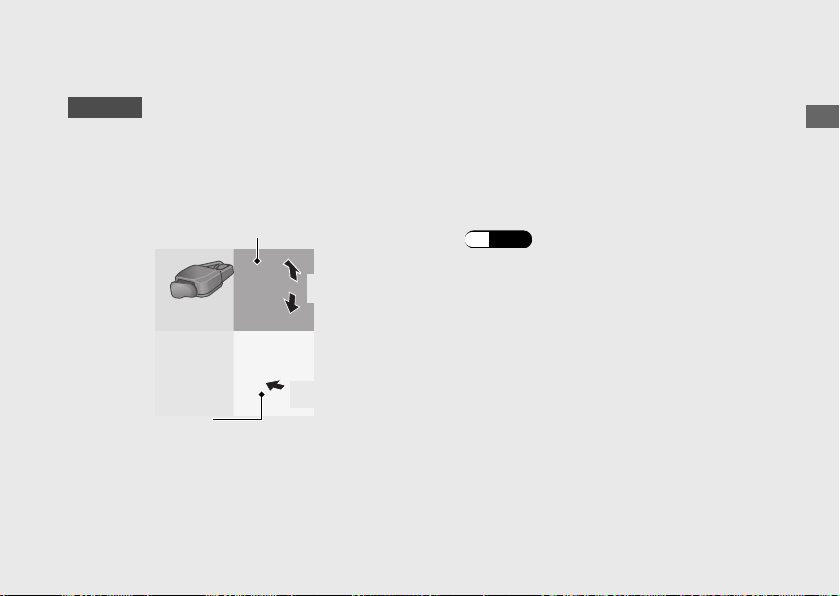
63
Continued
N-D switch
AT/MT switch
AT
MODE
MT
MODE
Level 1
Level 2
Level 3

Changing between Neutral and AT
MODE/MT MODE
Changing from Neutral (N) to AT MODE
Press the
D-S
side of the N-D switch (a).
The D mode indicator comes on, “1” is shown
in the gear position indicator and first gear is
selected.
Changing from AT or MT MODE to
Neutral
Press N on the N-D switch (b).
Changing between D mode and S mode
while in AT MODE
Press the
D-S
side of the N-D switch. The S
or D mode indicator comes on (c, d).
Changing between AT MODE and MT
MODE
Press the AT/MT switch (e).
The S or D indicator goes out while MT
MODE is selected (f).
Operation Guide
66
Shifting Gears (Continued)
Gear position indicator
AT/MT
switch

Fuel type: Unleaded gasoline only
Recommended fuel octane number:
Pump Octane Number (PON) 86 or higher.
Tank capacity:
3.73 US gal (14.1 L)
#
Refueling and Fuel Guidelines
(P.14)
Opening the Fuel Fill Cap
a
Open the rear seat.
(P.69)
b
Turn the fuel fill cap counterclockwise until it
stops and remove the cap.
Closing the Fuel Fill Cap
a
Install and tighten the fuel fill cap firmly by
turning it clockwise.
u Make sure that the arrow marks on the
cap and fuel tank are aligned.
b
Close the rear seat.
Do not fill with fuel above the lower edge of
the filler neck.
3WARNING
Gasoline is highly flammable and
explosive. You can be burned or
seriously injured when handling fuel.
• Stop the engine, and keep heat,
sparks, and flame away.
• Handle fuel only outdoors.
• Wipe up spills immediately.
Operation Guide
70
Refueling (Continued)
Fuel fill cap
Lower edge of
filler neck
Arrow marks

Storage Equipment
Luggage Box Open
a
Insert the ignition key into the lock, and turn
the key clockwise.
b
Pull up the front of the luggage box lid.
Close
a
Push down the front of the luggage box lid
until it locks in place.
u Make sure that the tab is locked securely
in position to pull up the front of the
luggage box lid lightly.
u The lock automatically when closed.
Take care not to lock your key in the
luggage box.
b
Remove the key.
Never exceed the maximum weight limit.
Maximum Weight: 11.0 lb (5.0 kg)
u Do not store any items that are flammable
or susceptible to heat damage.
Operation Guide
71
Continued
Ignition
key
Tab
Luggage box lid
Luggage box
Lock

Tool Kit
The tool kit is located on the maintenance lid
(in the luggage box) by the rubber strap.
#
Opening the luggage box.
(P.71)
Document Bag
The document bag is located in the owner’s
manual box (in the luggage box).
Opening the owner’s manual Box
a
Remove the clip.
(P.98)
b
Open the owner’s manual box lid.
Closing owner’s manual Box
a
Close the owner’s manual box lid.
b
Install the clip.
Operation Guide
73
Continued
Maintenance lid
Rubber
strap
Tool kit
Clip
Owner's manual
box lid
Document bag

Importance of Maintenance ........................... P. 76
Maintenance Schedule...................................
.. P. 78
Maintenance Record......................................... P. 81
Maintenance Fundamentals ...........................P. 82
Removing & Installing Body Components..P. 97
Battery.................................................................... P. 97
Clip.......................................................................... P. 98
Lower Cowl ...........................................................P. 99
Maintenance Lid................................................P. 101
Spark Plug......................................................... P. 102
Engine Oil.......................................................... P. 105
Coolant .............................................................. P. 111
Brakes................................................................. P. 113
Side Stand ......................................................... P. 116
Drive Chain ....................................................... P. 117
Clutch .................................................................P. 121
Throttle .............................................................. P. 124
Crankcase Breather......................................... P. 126
Other Adjustments.......................................... P. 127
Adjusting the Headlight Aim..........................P. 127
Adjusting the Brake Lever............................... P. 128
Please read “Importance of Maintenance” and “Maintenance Fundamentals” carefully
before attempting any maintenance. Refer to “Specifications” for service data.
An optional larger tool kit may be available.
Check with your Honda dealer's parts department.
Maintenance

Maintenance Safety
Always read the maintenance instructions
before you begin each task, and make sure that
you have the tools, parts, and skills required.
We cannot warn you of every conceivable
hazard that can arise in performing
maintenance. Only you can decide whether or
not you should perform a given task.
Follow these guidelines when performing
maintenance.
● Stop the engine and remove the key.
● Place your vehicle on a firm, level surface
using the side stand or a maintenance stand
to provide support.
● Allow the engine, muffler, brakes, and other
high-temperature parts to cool before
servicing as you can get burned.
● Run the engine only when instructed, and
do so in a well-ventilated area.
Importance of Maintenance
Maintenance
77

Maintenance Schedule
The maintenance schedule specifies the
maintenance requirements necessary to ensure
safe, dependable performance, and proper
emission control.
Maintenance work should be performed in
accordance with Honda's standards and
specifications by properly trained and equipped
technicians. Your dealer meets all of these
requirements. All scheduled maintenance is
considered a normal owner operating cost and
will be charged to you by your dealer. Keeping
an accurate maintenance record will help
ensure your vehicle is properly maintained.
2 P. 81
Make sure whoever performs the scheduled
maintenance completes the maintenance
record. Retain all service documents. If you sell
your vehicle, these service documents should
be transferred with the vehicle to the new
owner.
Maintenance
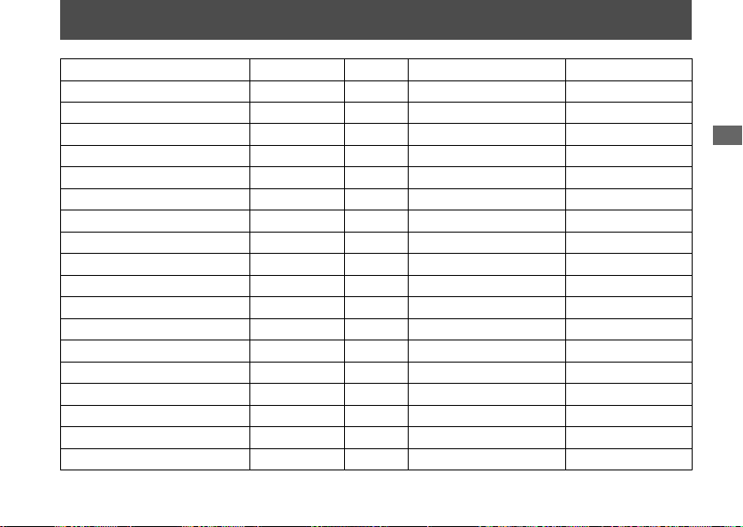
78

Items
Frequency
*1
× 1,000 mi
0.6 4 8 12 16 20 24
Regular
Replace
Refer to
page
× 1,000 km
1.0 6.4 12.8 19.2 25.6 32.0 38.4
Emission-Related Items
Fuel Line
–
Throttle Operation 124
Air Cleaner
*2
96
Crankcase Breather
*3
126
Spark Plug
Every 16,000 mi (25,600 km): Every 32,000 mi (51,200 km):
102
Valve Clearance –
Engine Oil
1 Year
107
Engine Oil Filter
107
Clutch Oil Filter
*6
109
Engine Idle Speed –
Radiator Coolant
*7
3 Years
111
Cooling System
–
Evaporative Emission Control System
*4
–
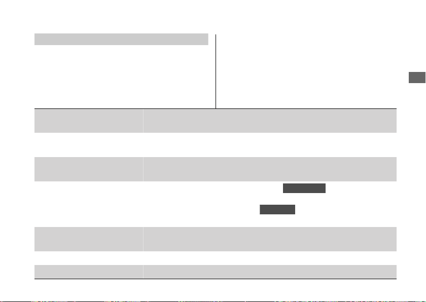
Maintenance Level Maintenance Legend
:
Intermediate. We recommend service by your dealer, unless
you have the necessary tools and are mechanically skilled.
Procedures are provided in an official Honda Service
Manual (2 P. 168).
:
:
:
:
Inspect (clean, adjust, lubricate, or replace if necessary)
Replace
Lubricate
Clean
: Technical. In the interest of safety, have your vehicle
serviced by your dealer.
Maintenance Schedule
Maintenance
79
Continued

Items
Frequency
*1
× 1,000 mi
0.6 4 8 12 16 20 24
Regular
Replace
Refer to
page
× 1,000 km
1.0 6.4 12.8 19.2 25.6 32.0 38.4
Non-Emission-Related Items
Drive Chain
Every 600 mi (1,000 km):
117
Drive Chain Slider 120
Brake Fluid
*7
2 Years
113
Brake Pads Wear
114
Brake System 82
Brake Light Switch 115
Brake Lock Operation
*6
115
Headlight Aim 127
Clutch System
*5
121
Side Stand 116
Suspension –
Nuts, Bolts, Fasteners –
Wheels/Tires 92
Steering Head Bearings –
Notes:
*1 : At higher odometer readings, repeat at the frequency
interval established here.
*2 : Service more frequently when riding in unusually wet or
dusty areas.
*3 : Service more frequently when riding in rain or at full
throttle.
*4 : 50 STATE (meets California).
*5 : NC750X and NC750XA.
*6 : NC750XD.
*7 : Replacement requires mechanical skill.
Maintenance Schedule
Maintenance
80
Maintenance Record
Distance Odometer Date Performed By: Notes
600 miles (1,000 km)
4,000 miles (6,400 km)
8,000 miles (12,800 km)
12,000 miles (19,200 km)
16,000 miles (25,600 km)
20,000 miles (32,000 km)
24,000 miles (38,400 km)
28,000 miles (44,800 km)
32,000 miles (51,200 km)
36,000 miles (57,600 km)
40,000 miles (64,000 km)
44,000 miles (70,400 km)
48,000 miles (76,800 km)
52,000 miles (83,200 km)
56,000 miles (89,600 km)
60,000 miles (96,000 km)
64,000 miles (102,400 km)
68,000 miles (108,800 km)
Maintenance
81
Tires and wheels
Check the air pressure (2 P. 92), examine tread for wear and damage
(2 P. 92), and check the wheels for damage.
Fluid levels
Check the engine oil level (
2 P. 105), engine coolant level (2 P. 111),
and brake fluid level (2 P. 113).
Lights
Check that the headlight, position lights, brake light, taillight, license
plate light and turn signals are working properly.
Controls
Check the freeplay of the clutch lever (
NC750X/XA
) (2 P. 121 ) and
throttle grip (2 P. 124), Check the front brake lever (2 P. 128), rear
brake pedal and parking brake (
NC750XD
) (2 P. 115 ) operate
properly.
Drive chain
Check the slack (2 P. 117), adjust the slack (2 P. 118), and lubricate
(2 P. 90) as needed.
Fuses Check that you have a full supply of spare fuses.
Nuts & bolts Check the major nuts and bolts, and tighten as needed.
Periodic Checks
You should also perform other periodic
maintenance checks at least once a month
regardless of how often you ride, or more often
if you ride frequently.
Also, check the odometer reading against the
Maintenance Schedule and perform all
maintenance that is due. 2 P. 78
Maintenance Fundamentals
Maintenance
83

NOTICE
Jump starting using an automobile battery can damage your
vehicle's electrical system and is not recommended. Bump
starting is also not recommended.
NOTICE
Installing non-Honda electrical accessories can overload the
electrical system, discharging the battery and possibly
damaging the system.
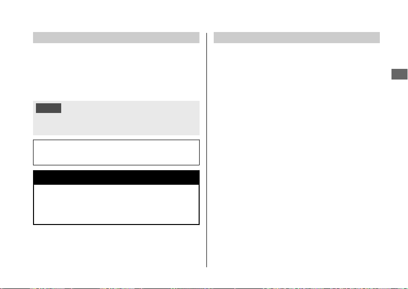
Fuses
Fuses protect the electrical circuits on your
vehicle. If something electrical on your vehicle
stops working, check for and replace any blown
fuses. 2 P. 148
#
Inspecting and Replacing Fuses
Turn the ignition switch to the OFF position to
remove and inspect fuses. If a fuse is blown,
replace with a fuse of the same rating. For fuse
ratings, see “Specifications.” 2 P. 176
NOTICE
Replacing a fuse with one that has a higher rating greatly
increases the chance of damage to the electrical system.
If a fuse fails repeatedly, you likely have an
electrical fault. Have your vehicle inspected by
your dealer.
Maintenance Fundamentals
Maintenance
87
Blown fuse

Engine Oil
Engine oil consumption varies and oil quality
deteriorates according to riding conditions and
time elapsed.
Check the engine oil level regularly, and add the
recommended engine oil if necessary. Dirty oil or
old oil should be changed as soon as possible.
#
Selecting the Engine Oil
For recommended engine oil, see
“Specifications.” 2 P. 175
If you use non-Honda engine oil, check the
label to make sure that the oil satisfies all of the
following standards:
● JASO T 903 standard
*1
: MA
● SAE standard
*2
: 10W-30
● API classification
*3
: SG or higher
*1.
The JASO T 903 standard is an index for engine
oils for 4-stroke motorcycle engines. There are
two classes: MA and MB. For example, the
following label shows the MA classification.
*2.
The SAE standard grades oils by their viscosity.
*3.
The API classification specifies the quality and
performance rating of engine oils. Use SG or
higher oils, excluding oils marked as “Energy
Conserving” or “Resource Conserving” on the
circular API service symbol.
Maintenance Fundamentals
Maintenance
88
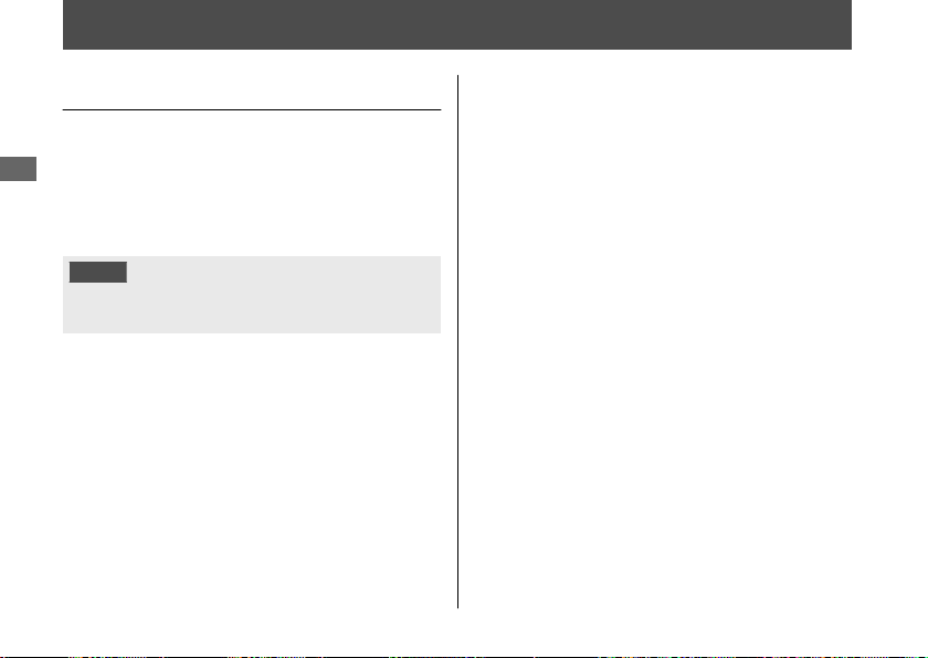
Oil code
Oil classification
Not recommended Recommended
Brake Fluid
Do not add or replace brake fluid, except in an
emergency. Use only fresh brake fluid from a
sealed container. If you do add fluid, have the
brake system serviced by your dealer as soon as
possible.
NOTICE
Brake fluid can damage plastic and painted surfaces.
Wipe up spills immediately and wash thoroughly.
Recommended brake fluid:
Honda DOT 4 Brake Fluid or equivalent
3WARNING
Clean filler cap before removing. Use
only DOT 4 fluid from a sealed
container.
Drive Chain
The drive chain must be inspected and
lubricated regularly. Inspect the chain more
frequently if you often ride on bad roads, ride at
high speed, or ride with repeated fast
acceleration. 2 P. 117
If the chain does not move smoothly, makes
strange noises, has damaged rollers, has loose
pins, has missing O-rings, or kinks, have the
chain inspected by your dealer.
Maintenance Fundamentals
Maintenance
89
Continued

#
Inspecting Tread Depth
Inspect the tread wear indicators. If they
become visible, replace the tires immediately.
For safe riding, you should replace the tires
when the minimum tread depth is reached.
3WARNING
Riding on tires that are excessively worn
or improperly inflated can cause a crash
in which you can be seriously hurt or
killed.
Follow all instructions in this owner's
manual regarding tire inflation and
maintenance.
Maintenance Fundamentals
Maintenance
93
Continued
Wear indicator
location mark
or TWI

Have your tires replaced by your dealer.
For recommended tires, air pressure and
minimum tread depth, see “Specifications.”
2 P. 175
Follow these guidelines whenever you replace
tires.
● Use the recommended tires or equivalents
of the same size, construction, speed rating,
and load range.
● Have the wheel balanced with Honda
Genuine balance weights or equivalent after
the tire is installed.
● Do not install a tube inside a tubeless tire on
this vehicle. Excessive heat build-up can
cause the tube to burst.
● Use only tubeless tires on this vehicle.
The rims are designed for tubeless tires, and
during hard acceleration or braking, a tube-
type tire could slip on the rim and cause the
tire to rapidly deflate.
3WARNING
Installing improper tires on your vehicle
can adversely affect handling and
stability, and can cause a crash in which
you can be seriously hurt or killed.
Always use the size and type of tires
recommended in this owner's manual.
Maintenance Fundamentals
Maintenance
94
Tire Service Life
The service life of your tires is dependent on
many factors, including, but not limited to,
riding habits, road conditions, vehicle loading,
tire air pressure, maintenance history, speed,
and environmental conditions (even when the
tires are not in use).
In addition to your regular inspections and
maintenance, it is recommended that you have
annual inspections performed once the tires
reach 5 years old. It is also recommended that
all tires be removed from service after 10 years
from the date of manufacture, regardless of
their condition or state of wear.
The last four digits of the TIN (tire identification
number) indicate the date of manufacture.
#
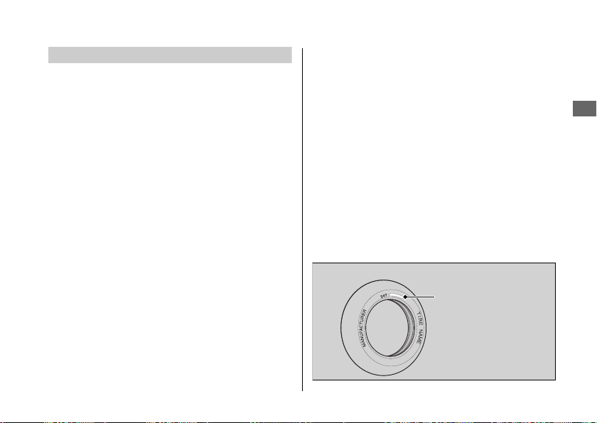
Tire Identification Number (TIN)
The tire identification number (TIN) is a group
of numbers and letters located on the sidewall
of the tire.
a b c
DOT XXXX XXXX 22 09
DOT: This indicates that the tire meets all
requirements of the U.S.
Department of Transportation.
a XXXX:
Factory code
b XXXX:
Tire type code
c 22 09:
Date of manufacture (week & year).
Example: week 22 in year 09.
Maintenance Fundamentals
Maintenance
95
Tire Labeling Example
Tire identification
number (TIN)

Lower Cowl
NC750X/XA
#
Removal
1.
Remove the screws.
2.
Remove the lower cowl by releasing its
prongs from the grommets.
#
Installation
Install the parts in the reverse order of
removal.
Removing & Installing Body Components u Lower Cowl
Maintenance
99
Continued
Lower cowl Grommets Screw
Screw Prongs
NC750XD
#
Removal
1.
Remove the screw A and B.
2.
Remove the lower cowl by releasing its
prongs from the grommets.
#
Installation
Install the parts in the reverse order of
removal.
Removing & Installing Body Components u Lower Cowl
Maintenance
100
Lower cowl Grommets
Screw BScrew A Prongs
Spark Plug
Checking Spark Plug
For the recommended spark plugs, see
“Specifications.” 2 P. 175
Use only the recommended type of spark
plugs in the recommended heat range.
NOTICE
Using a spark plug with an improper heat range
can cause engine damage.
This vehicle uses the spark plugs that have an
iridium coated center electrode.
Be sure to observe the following when
servicing the spark plugs.
● Do not clean the spark plugs. If an
electrode is contaminated with
accumulated objects or dirt, replace the
spark plug with a new one.
● To check the spark plug gap, use only a
“wire-type feeler gauge.” To prevent
damaging the iridium coating of the
center electrode, never use a “leaf-type
feeler gauge.”
● Do not adjust the spark plug gap. If the
gap is out of specification, replace the
spark plug with a new one.
Maintenance
102
1.
Remove the lower cowl. 2 P. 99
2.
Disconnect the spark plug caps from the
spark plugs.
3.
Clean any dirt from around the spark plug
bases.
4.
Remove the spark plugs using a suitable
spark plug wrench.
5.
Inspect the electrodes and center
porcelain for deposits, erosion or carbon
fouling.
u If the erosion or deposit is heavy,
replace the plug.
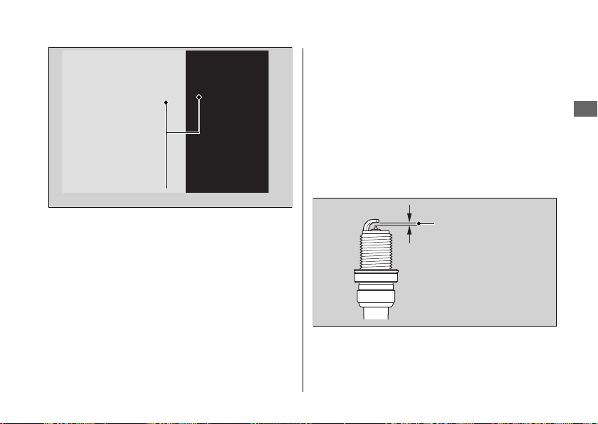
6.
Make sure that a 1.2 mm wire-type feeler
gauge cannot be inserted between the
spark plug gap. If the gauge fits in the
gap, replace the plug with a new one.
Spark Plug u Checking Spark Plug
Maintenance
103
Continued
Spark plug caps
Spark plug gap
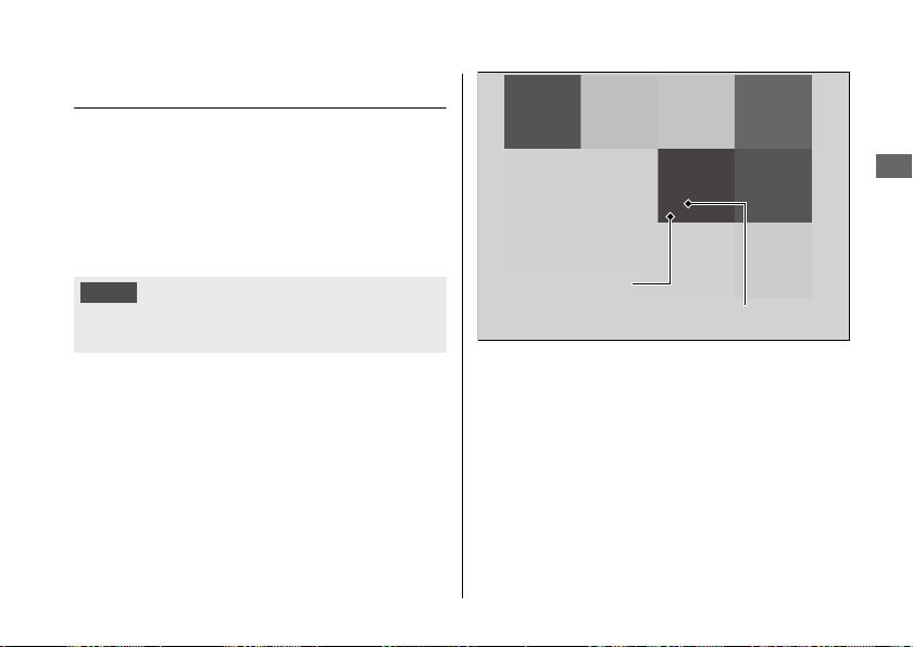
Changing Engine Oil & Filter
Changing the oil and filter requires special
tools. We recommend that you have your
vehicle serviced by your dealer.
Use a new Honda Genuine oil filter or
equivalent specified for your model.
NOTICE
Using the wrong oil filter can result in serious damage to the
engine.
1.
Remove the lower cowl. 2 P. 99
2.
If the engine is cold, idle the engine for 3
to 5 minutes.
3.
Turn the ignition switch to the OFF
position and wait for 2 to 3 minutes.
4.
Place your vehicle on a firm, level surface.
5.
Place a drain pan under the drain bolt.
6.
Remove the oil fill cap/dipstick, drain bolt,
and sealing washer to drain the oil.
7.
Remove the oil filter with a filter wrench
and let the remaining oil drain out. Make
sure the prior seal is not stuck to the
engine.
u Discard the oil and oil filter at an
approved recycling center.
Engine Oil u Changing Engine Oil & Filter
Maintenance
107
Continued
Sealing washer
Drain bolt
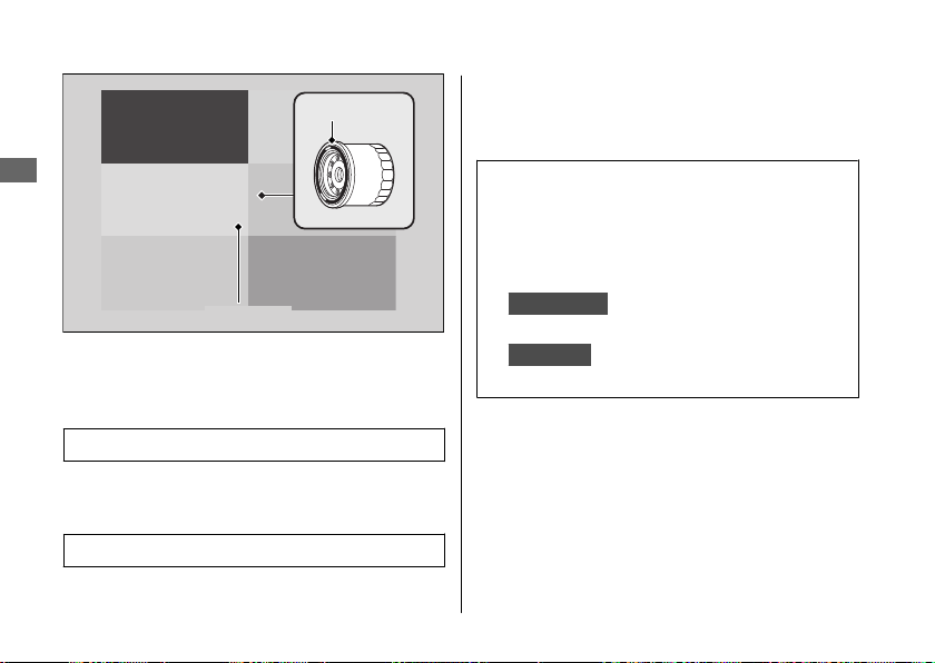
8.
Apply a thin coat of engine oil to the
rubber seal of a new oil filter.
9.
Install the new oil filter and tighten.
Torque: 19 lbf·ft (26 N·m, 2.7 kgf·m)
10.
Install a new sealing washer onto the
drain bolt. Tighten the drain bolt.
Torque: 22 lbf·ft (30 N·m, 3.1 kgf·m)
11.
Fill the crankcase with the recommended
oil (2 P. 88, 2 P. 175) and install the oil fill
cap/dipstick.
Required oil
When changing oil & engine oil
filter:
3.6 US qt (3.4 L)
When changing oil only:
NC750X/XA
3.3 US qt (3.1 L)
NC750XD
3.4 US qt (3.2 L)
12.
Check the oil level. 2 P. 105
13.
Check that there are no oil leaks.
14.
Install the lower cowl.
Engine Oil u Changing Engine Oil & Filter
Maintenance
108
Rubber seal
Oil filter

Changing Clutch Oil Filter
NC750XD
Use a new Honda Genuine clutch oil filter or
equivalent specified for your model.
NOTICE
Using the wrong clutch oil filter can result in serious damage
to the transmission.
1.
Follow the steps 1-7 of Changing Engine
Oil & Filter. 2 P. 107
2.
Remove the clutch oil filter cover, clutch
oil filter and spring by removing the
clutch oil filter cover bolts.
u Discard the oil and clutch oil filter at an
approved recycling center.
Engine Oil u Changing Clutch Oil Filter
Maintenance
109
Continued
Clutch oil filter cover
Rubber seal
“OUT-SIDE”
mark
O-ring
Clutch
oil
filter
SpringBolts
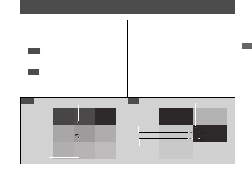
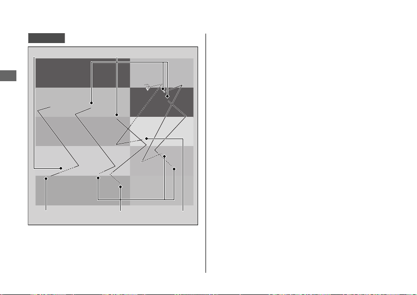
Brakes
Checking Brake Fluid
1.
Place your vehicle in an upright position
on a firm, level surface.
2.
Front
Check that the brake fluid reservoir
is horizontal and that the fluid level is
above the LOWER level mark.
Rear
Check that the brake fluid reservoir
is horizontal and that the fluid level is
between the LOWER level and UPPER
level marks.
If the brake fluid level in either reservoir is
below the LOWER level mark or the brake
lever and pedal freeplay becomes excessive,
inspect the brake pads for wear.
If the brake pads are not worn, you most
likely have a leak. Have your vehicle
inspected by your dealer.
Maintenance
113
Front brake fluid reservoir
LOWER
level mark
UPPER level
mark
LOWER level
mark
Rear brake fluid reservoir
Front Rear
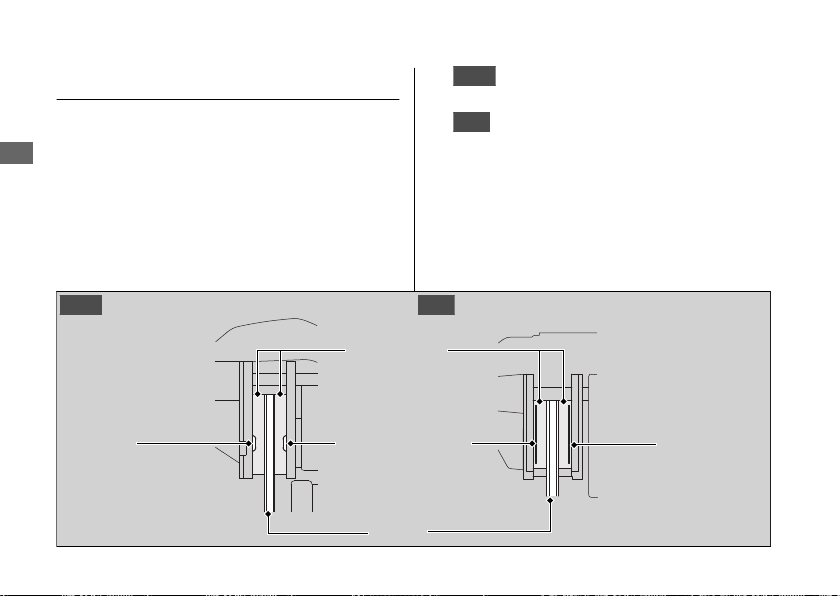
Inspecting the Brake Pads
Check the condition of the brake pad wear
indicators.
The pads need to be replaced if a brake pad
is worn to the indicator.
1.
Front
Inspect the brake pads from below
the brake caliper.
2.
Rear
Inspect the brake pads from the rear
right of the vehicle.
If necessary have the pads replaced by your
dealer.
Always replace both left and right brake pads
at the same time.
Brakes u Inspecting the Brake Pads
Maintenance
114
Front Rear
Wear
indicator
Brake Pads
Discs
Wear indicators
Wear
indicator
Checking the Parking Brake
NC750XD
Place your vehicle on a firm, level surface.
Stop the engine and push your vehicle while
set the parking brake to check the efficacy of
the parking brake.
If the efficacy of the parking brake becomes
weak, have the brake adjusted by your
dealer.
Adjusting the Brake Light
Switch
Check the operation of the brake light switch.
Hold the brake light switch and turn the
adjusting nut in the direction A if the switch
operates too late, or turn the nut in the
direction B if the switch operates too soon.
Brakes u Checking the Parking Brake
Maintenance
115
Parking brake lever
Brake light switch
Adjusting nut
B
A

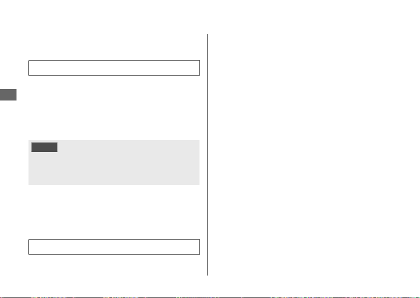
Drive Chain
Inspecting the Drive Chain
Slack
Check the drive chain slack at several points
along the chain. If the slack is not constant at
all points, some links may be kinked and
binding.
Have the chain inspected by your dealer.
1.
Shift the transmission to Neutral. Stop the
engine.
2.
Place your vehicle on its side stand on a
firm, level surface.
3.
Check the slack in the lower half of the
drive chain midway between the
sprockets.
Drive chain slack:
1 3/16 - 1 9/16 in (30 - 40 mm)
u Do not ride your vehicle if the slack
exceeds
2 3/8 in (60 mm)
.
4.
Roll the vehicle forward and check that
the chain moves smoothly.
5.
Inspect the sprockets. 2 P. 89
6.
Clean and lubricate the drive chain.
2 P. 90
Maintenance
117

Adjusting the Drive Chain Slack
Adjusting the chain requires special tools.
Have the drive chain slack adjusted by your
dealer.
NC750XA/XD
When adjusting the drive chain slack, be
careful not to damage the wheel speed
sensor and pulser ring.
1.
Shift the transmission to Neutral. Stop the
engine.
2.
Place your vehicle on its side stand on a
firm, level surface.
3.
Loosen the rear axle nut.
4.
Loosen the lock nuts on both sides of the
swingarm.
Drive Chain u Adjusting the Drive Chain Slack
Maintenance
118
Lock nut
Wheel speed sensor
NC750XA/XD
Rear axle nut
Adjusting nut
Pulser ring
NC750XA/XD
Rear edge of
adjusting slot
Chain adjuster
index mark
Adjusting nut Lock nut
5.
Turn both adjusting nuts an equal
number of turns until the correct drive
chain slack is obtained. Turn the adjusting
nuts clockwise to tighten the chain. Turn
the adjusting nuts counterclockwise to
provide more slack. Adjust the slack at a
point midway between the drive sprocket
and the driven sprocket.
Check the drive chain slack. 2 P. 117
6.
Check rear axle alignment by making sure
the chain adjuster index marks align with
the rear edge of the adjusting slots. Both
marks should correspond. If the axle is
misaligned, turn the right or left adjusting
nut until the marks are aligned and
recheck chain slack.
7.
Tighten the rear axle nut.
Torque: 72 lbf·ft (98 N·m, 10.0 kgf·m)
8.
Tighten the drive chain adjusting nuts
lightly, then hold the adjusting nuts and
tighten the lock nuts.
Torque: 15 lbf·ft (21 N·m, 2.1 kgf·m)
9.
Recheck drive chain slack.
If a torque wrench was not used for
installation, see your dealer as soon as
possible to verify proper assembly.
Improper assembly may lead to loss of
braking capacity.
Drive Chain u Adjusting the Drive Chain Slack
Maintenance
119
Continued

Clutch
Checking the Clutch
NC750X/XA
#
Checking the Clutch Lever Freeplay
Check the clutch lever freeplay.
Freeplay at the clutch lever:
3/8 - 13/16 in (10 - 20 mm)
Check the clutch cable for kinks or signs of
wear. If necessary have it replaced by your
dealer.
Lubricate the clutch cable with a
commercially available cable lubricant to
prevent premature wear and corrosion.
NOTICE
Improper freeplay adjustment can cause premature clutch
wear.
Maintenance
121
Clutch lever
Freeplay

Throttle
Checking the Throttle
With the engine off, check that the throttle
rotates smoothly from fully closed to fully
open in all steering positions and throttle
freeplay is correct. If the throttle does not
move smoothly, close automatically, or if the
cable is damaged, have the vehicle inspected
by your dealer.
Freeplay at the throttle grip flange:
1/16 - 1/4 in (2 - 6 mm)
Maintenance
124
Freeplay
Flange

Adjusting the Throttle Freeplay
NC750X/XA
1.
Loosen the lock nut.
2.
Turn the adjuster until the freeplay is 1/16
- 1/4 in (2 - 6 mm).
3.
Tighten the lock nut and inspect the
throttle action again.
NC750XD
1.
Slide the cable boot.
2.
Loosen the lock nut.
3.
Turn the adjuster until the freeplay is 1/16
- 1/4 in (2 - 6 mm).
4.
Tighten the lock nut, return the cable
boot, and inspect the throttle action
again.
Throttle u Adjusting the Throttle Freeplay
Maintenance
125
Throttle grip
Adjuster
Lock nut
+
-
Throttle grip
Adjuster
Lock nut
+
-
Cable boot

Crankcase Breather
Cleaning the Crankcase
Breather
1.
Place a suitable container to receive
deposits.
2.
Remove the crankcase breather tube plug
from the tube and drain deposits into the
container.
3.
Reinstall the crankcase breather tube
plug.
Maintenance
126
Crankcase breather tube plug
Crankcase
breather tube

Other Adjustments
Adjusting the Headlight Aim
You can adjust vertical aim of the headlight
for proper alignment. Turn the pinion in or
out as necessary using provided Phillips
screwdriver.
Obey local laws and regulations.
Maintenance
127
Pinion
Raise
Lower

Engine Will Not Start......................................P. 130
Overheating (High coolant temperature
indicator is on).............................................
.. P. 131
Warning Indicators On or Flashing............. P. 132
Low Oil Pressure Indicator .............................. P. 132
PGM-FI (Programmed Fuel Injection)
Malfunction Indicator Lamp (MIL)............... P. 132
ABS (Anti-lock Brake System) Indicator ....... P. 133
Torque Control Indicator................................. P. 134
If the “–” Indicator is Blinking in the Gear
Position Window While Riding..................P. 135
Other Warning Indications ...........................P. 136
Fuel Gauge Failure Indication......................... P. 136
Tire Puncture .................................................... P. 137
Electrical Trouble............................................. P. 145
Battery Goes Dead............................................ P. 145
Burned-out Light Bulb .....................................P. 145
Blown Fuse..........................................................P. 148
Troubleshooting

Engine Will Not Start
Starter Motor Operates But
Engine Does Not Start
Check the following items:
● Check the correct engine starting
sequence. 2 P. 58
● Check that there is gasoline in the fuel
tank.
● Check if the PGM-FI malfunction indicator
lamp (MIL) is on.
u If the indicator lamp is on, contact
your dealer as soon as possible.
Starter Motor Does Not
Operate
Check the following items:
● Check the correct engine starting
sequence. 2 P. 58
● Make sure engine stop switch is in the
(Run) position. 2 P. 51
● Check for a blown fuse. 2 P. 148
● Check for a loose battery connection
(2 P. 97) or battery terminal corrosion
(2 P. 85).
● Check the condition of the battery.
2 P. 145
If the problem continues, have your vehicle
inspected by your dealer.
Troubleshooting
130

Overheating (High coolant temperature indicator is on)
The engine is overheating when the following
occurs:
● High coolant temperature indicator
comes on.
● Acceleration becomes sluggish.
If this occurs, pull safely to the side of the
road and perform the following
procedure.
Extended fast idling may cause the high
coolant temperature indicator to come on.
NOTICE
Continuing to ride with an overheated engine can cause
serious damage to the engine.
1.
Stop the engine using the ignition switch,
and then turn the ignition switch to the
ON position.
2.
Check that the radiator fan is operating,
and then turn the ignition switch to the
OFF position.
If the fan is not operating:
Suspect a fault. Do not start the engine.
Transport your vehicle to your dealer.
If the fan is operating:
Allow the engine to cool with the ignition
switch in the OFF position.
3.
After the engine has cooled, inspect the
radiator hose and check if there is a leak.
2 P. 111
If there is a leak:
Do not start the engine. Transport your
vehicle to your dealer.
4.
Check the coolant level in the reserve
tank. 2 P. 111
u Add coolant as necessary.
5.
If 1-4 check normal, you may continue
riding, but closely monitor the high
coolant temperature indicator.
Troubleshooting
131
Warning Indicators On or Flashing
Low Oil Pressure Indicator
If the low oil pressure indicator comes on,
pull safely to the side of the road and stop
the engine.
NOTICE
Continuing to ride with low oil pressure can cause serious
damage to the engine.
1.
Check the engine oil level, and add oil as
necessary. 2 P. 105, 2 P. 106
2.
Start the engine.
u Only continue riding if the low oil
pressure indicator goes off.
Rapid acceleration may momentarily cause
the low oil pressure indicator to come on,
especially if the oil is at or near the low level.
If the low oil pressure indicator stays on when
the oil level is at the proper level, stop the
engine and contact your dealer.
If the engine oil level goes down rapidly, your
vehicle may have a leak or another serious
problem. Have your vehicle inspected by
your dealer.
PGM-FI (Programmed Fuel
Injection) Malfunction
Indicator Lamp (MIL)
If the indicator comes on while riding, you
may have a serious problem with the PGM-FI
system. Reduce speed and have your vehicle
inspected by your dealer as soon as possible.
Troubleshooting
132
Tire Puncture
Repairing a puncture or removing a wheel
requires special tools and technical expertise.
We recommend you have this type of service
performed by your dealer.
After an emergency repair, always have the
tire inspected/replaced by your dealer.
Emergency Repair Using a Tire
Repair Kit
If your tire has a minor puncture, you can
make an emergency repair using a tubeless
tire repair kit.
Follow the instructions provided with the
emergency tire repair kit.
Riding your vehicle with a temporary tire
repair is very risky. Do not exceed 30 mph
(50 km/h). Have the tire replaced by your
dealer as soon as possible.
3WARNING
Riding your vehicle with a temporary
tire repair can be risky. If the temporary
repair fails, you can crash and be
seriously injured or killed.
If you must ride with a temporary tire
repair, ride slowly and carefully and do
not exceed 30 mph (50 km/h) until the
tire is replaced.
Removing Wheels
Follow these procedures if you need to
remove a wheel in order to repair a
puncture.
Troubleshooting
137
Continued
NC750XA/XD
When removing and installing the wheel, be
careful not to damage the wheel speed
sensor and pulser ring.
#
Front Wheel
Removal
1.
Place your vehicle on a firm, level surface.
2.
Cover right side of the front wheel and
brake caliper with protective tape or cloth.
3.
On the right side, remove the mounting
bolts and remove the brake caliper.
u Support the brake caliper assembly so
that it doesn’t hang from the brake
hose. Do not twist the brake hose.
u Avoid getting grease, oil, or dirt on the
disc or pad surfaces.
u Do not pull the brake lever while the
brake caliper is removed.
u Take care to prevent the brake caliper
from scratching the wheel during
removal.
Tire Puncture u Removing Wheels
Troubleshooting
138
Mounting boltsBrake caliper
Wheel speed sensor
NC750XA/XD
Collar
Pulser ring
NC750XA/XD

4.
Loosen the axle pinch bolt.
5.
Support your vehicle securely and raise
the front wheel off the ground using a
maintenance stand or a hoist.
6.
On the left side, loosen and withdraw the
front axle shaft, and remove the side
collars and wheel.
Installation
1.
Attach the side collars to the wheel.
2.
On the left side, place the wheel between
the fork legs and insert the front axle shaft
to the end, through the left fork leg and
wheel hub.
3.
Tighten the axle shaft.
Torque: 55 lbf·ft (74 N·m, 7.5 kgf·m)
Tire Puncture u Removing Wheels
Troubleshooting
139
Continued
Axle pinch bolt
Front axle shaftCollar
4.
Install the brake caliper and tighten the
mounting bolts.
Torque: 22 lbf·ft (30 N·m, 3.1 kgf·m)
u Take care to prevent the brake caliper
from scratching the wheel during
installation.
u Use new mounting bolts when
installing the brake caliper.
NOTICE
When installing a wheel or caliper into original position,
carefully fit the brake disc between the pads to avoid
scratching them.
5.
Lower the front wheel on the ground.
6.
Apply the brake lever several times. Then,
pump the fork several times.
7.
Tighten the axle pinch bolt.
Torque: 16 lbf·ft (22 N·m, 2.2 kgf·m)
8.
Raise the front wheel off the ground
again, and check that the wheel rotates
freely after you release the brake.
9.
Uncover the protective tape or cloth.
If a torque wrench was not used for
installation, see your dealer as soon as
possible to verify proper assembly.
Improper assembly may lead to loss of
braking capacity.
Tire Puncture u Removing Wheels
Troubleshooting
140

6.
Remove the drive chain from the driven
sprocket by pushing the rear wheel
forward.
7.
Remove the rear axle shaft, washers,
brake caliper bracket, rear wheel and side
collars.
u Support the brake caliper assembly so
that it doesn’t hang from the brake
hose. Do not twist the brake hose.
u Avoid getting grease, oil, or dirt on the
disc or pad surfaces.
u Do not push the brake pedal while the
wheel is removed.
u
NC750XD
Do not pull the parking brake lever
while the wheel is removed.
Tire Puncture u Removing Wheels
Troubleshooting
142
Lock nut
Collar B
Adjusting nut
Rear axle shaft
Drive chain
Washer
Installation
1.
To install the rear wheel, reverse the
removal procedure.
u Take care to prevent the brake caliper
from scratching the wheel during
installation.
NOTICE
When installing a wheel or caliper into original position,
carefully fit the brake disc between the pads to avoid
scratching them.
2.
Make sure that the slot on the brake
caliper bracket is positioned in the lug on
the swingarm.
Tire Puncture u Removing Wheels
Troubleshooting
143
Continued
Lug
Swingarm
Brake caliper bracket
Slot

#
Headlight/Position Light
The headlights and position lights uses
several LEDs.
If there is an LED which is not turned on, see
your dealer for servicing.
#
Brake Light/Taillight
The brake light and taillight uses several
LEDs. If there is an LED which is not turned
on, see your dealer for servicing.
Electrical Trouble u Burned-out Light Bulb
Troubleshooting
146
Headlights
Position lights
Brake light/Taillight

#
Front/Rear Turn Signal Bulb
1.
Remove the screw and collar.
2.
Remove the turn signal lens and lens
packing.
3.
Slightly press the bulb and turn it
counterclockwise.
4.
Install a new bulb and parts in the reverse
order of removal.
#
License Plate Light Bulb
1.
Remove the screws.
2.
Remove the license plate light cover and
license plate light cover packing.
3.
Pull out the bulb without turning it.
4.
Install a new bulb and parts in the reverse
order of removal.
Electrical Trouble u Burned-out Light Bulb
Troubleshooting
147
Bulb
Lens packing
Collar
Screw
Turn signal lens
ScrewsLicense plate light cover
Bulb Cover packing

Keys..................................................................... P. 152
Instruments, Controls, & Other Features...P.
153
Caring for Your Vehicle.................................. P. 155
Storing Your Vehicle....................................... P. 159
Transporting Your Vehicle ............................ P. 160
You & the Environment .................................P. 160
Vehicle Identification Number..................... P. 161
Emission Control Systems ............................. P. 162
Catalytic Converter ......................................... P. 166
Oxygenated Fuels............................................P. 167
Authorized Manuals ....................................... P. 168
Warranty Coverage and Service .................. P. 169
Honda Contacts ............................................... P. 171
USA
Reporting Safety Defects ..................... P. 173
Information
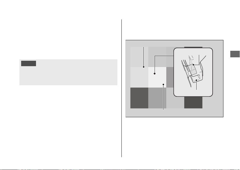
Keys
Ignition Key
This vehicle has two ignition keys and a key tag
with a key number and a bar code. Store the
spare key and the key tag in a safe location. To
make a duplicate key, take the spare key and
the key tag to your dealer or a locksmith.
If you lose all ignition keys and the key tag, the
ignition switch assembly will probably have to
be removed by your dealer to determine the
key number.
A metal key holder may cause damage to the
area surrounding the ignition switch.
Keys
Information
152
Ignition key Key tag
Key number and bar code

Instruments, Controls, &
Other Features
Ignition Switch
Leaving the ignition switch in the ON position
with the engine stopped will drain the battery.
Do not turn the key while riding.
Engine Stop Switch
Do not use the engine stop switch except in an
emergency. Doing so when riding will cause the
engine to suddenly turn off, making riding
unsafe.
If you stop the engine using the engine stop
switch, turn the ignition switch to the OFF
position. Failing to do so will drain the battery.
Odometer
The display locks at 999,999 when the read-out
exceeds 999,999.
Tripmeter
The tripmeters return to 0.0 when each read-
out exceeds 9,999.9.
Clock
The clock is displayed for 24 hours after the
ignition switch is turned to the OFF position.
Tachometer
Depending on the brightness of direct sunlight
or environmental conditions, it may be difficult
to distinguish the color of the tachometer
display.
Instruments, Controls, & Other Features
Information
153
Continued

Document Bag
The owner’s manual, registration, and insurance
information can be stored in the plastic
document bag located in the owner’s manual
box. 2 P. 73
Ignition Cut-off System
A banking (lean angle) sensor automatically
stops the engine and fuel pump if the vehicle
falls over. To reset the sensor, you must turn the
ignition switch to the OFF position and back to
the ON position before the engine can be
restarted.
Instruments, Controls, & Other Features
Information
154

#
Washing Precautions
Follow these guidelines when washing:
● Do not use high-pressure washers:
u High-pressure water cleaners can
damage moving parts and electrical
parts, rendering them inoperable.
u Water in the air intake can be drawn into
the throttle body and/or enter the air
cleaner.
● Do not direct water at the muffler:
u Water in the muffler can prevent starting
and causes rust in the muffler.
● Dry the brakes:
u Water adversely affects braking
effectiveness. After washing, apply the
brakes intermittently at low speed to
help dry them.
● Do not direct water in the luggage box:
u Water in the luggage box can damage
your documents and other belongings.
● Do not direct water at the air cleaner:
u Water in the air cleaner can prevent the
engine from starting.
● Do not direct water near the headlight:
u The headlight's inside lens may fog
temporarily after washing or while riding
in the rain. This does not impact the
headlight function.
However, if you see a large amount of
water or ice accumulated inside the
lens(es), have your vehicle inspected by
your dealer.
● Do not use wax or polishing compounds on
matte painted surface:
u Use a soft cloth or sponge, plenty of
water, and a mild detergent to clean
matte painted surfaces. Dry with a soft
clean cloth.
Caring for Your Vehicle
Information
156

Aluminum Components
Aluminum will corrode from contact with dirt,
mud, or road salt. Clean aluminum parts
regularly and follow these guidelines to avoid
scratches:
● Do not use stiff brushes, steel wool, or
cleaners containing abrasives.
● Avoid riding over or scraping against curbs.
Panels
Follow these guidelines to prevent scratches
and blemishes:
● Wash gently using a soft sponge and plenty
of water.
● To remove stubborn stains, use diluted
detergent and rinse thoroughly with plenty
of water.
● Avoid getting gasoline, brake fluid, or
detergents on the instruments, panels, or
headlight.
Windscreen
Using plenty of water, clean the windscreen with
a soft cloth or sponge. (Avoid using detergents
or any kind of chemical cleaner on the
windscreen.) Dry with a soft, clean cloth.
NOTICE
To avoid possible scratching or other damage, use only water
and a soft cloth or sponge to clean the windscreen.
For a dirtier windscreen, use a diluted neutral
detergent with a sponge and plenty of water.
Make sure to wash off all the detergent.
(Detergent residue may cause windscreen
cracks.)
Replace the windscreen if scratches cannot be
removed and they obstruct clear vision.
Take care to keep battery electrolyte, brake
fluid, or other chemical solvents off the
windscreen and screen garnish. They will
damage the plastic.
Caring for Your Vehicle
Information
157
Continued

Transporting Your Vehicle
If your vehicle needs to be transported, it
should be carried on a motorcycle trailer or a
flatbed truck or trailer that has a loading ramp
or lifting platform, and motorcycle tie-down
straps. Never try to tow your vehicle with a
wheel or wheels on the ground.
NOTICE
Towing your vehicle can cause serious damage
to the transmission.
You & the Environment
Owning and riding a vehicle can be enjoyable,
but you must do your part to protect the
environment.
Choose Sensible Cleaners
Use a biodegradable detergent when you wash
your vehicle. Avoid aerosol spray cleaners that
contain chlorofluorocarbons (CFCs) which
damage the atmosphere's protective ozone
layer.
Recycle Wastes
Put oil and other toxic wastes in approved
containers and take them to a recycling center.
Call your local or state office of public works or
environmental services to find a recycling center
in your area, and to get instructions on how to
dispose of non-recyclable wastes. Do not place
used engine oil in the trash, or pour it down a
drain or on the ground. Used oil, gasoline,
coolant, and cleaning solvents contain poisons
that can hurt refuse workers and contaminate
drinking water, lakes, rivers, and oceans.
Transporting Your Vehicle
Information
160

Vehicle Identification
Number
The VIN and engine serial number uniquely
identify your vehicle and are required in order
to register your vehicle. They may also be
required when ordering replacement parts.
You should record these numbers and keep
them in a safe place.
Vehicle Identification Number
Information
161
VIN
VIN
Engine number

Noise Emission Requirements
The EPA requires that vehicles built after
January 1, 1983 comply with applicable noise
emission standards for one year or 3,730 miles
(6,000 km) after the time of purchase when
operated and maintained according to the
instructions provided.
Exhaust Emission Control System
The exhaust emission control system includes
the following components that should not need
adjustment, although periodic inspection by
your dealer is recommended.
#
PGM-FI System
The PGM-FI (programmed fuel injection) system
uses sequential multiport fuel injection, and is
comprised of air intake, engine control, fuel
control, and exhaust control subsystems. The
engine control module (ECM) uses sensors to
determine how much air enters the engine, and
then controls how much fuel to inject.
#
Ignition Timing Control System
The ignition timing control system adjusts the
ignition timing to reduce the amount of HC,
CO, and NOx produced.
#
Catalytic Converters
The exhaust system contains one or more
catalytic converters. Catalytic converters use a
catalyst to convert most of the harmful exhaust
gas compounds into harmless compounds.
Evaporative Emission Control System
50 STATE (meets California)
An evaporative emissions control system uses a
canister filled with charcoal to adsorb fuel vapor
from the fuel tank while the engine is off. The
vapor is drawn into the engine and burned
while riding.
Emission Control Systems
Information
163
Continued

Crankcase Emissions Control System
The engine is equipped with a closed crankcase
system to prevent discharging crankcase
emissions into the atmosphere.
Blow-by gas is returned to the combustion
chamber through the air cleaner and throttle
body.
Fuel Permeation Emission Control
The fuel tank, fuel hoses, and fuel vapor charge
hoses use fuel permeation control technologies
to prevent fuel vapor emissions. Tampering with
these components to reduce or defeat the
effectiveness of the fuel permeation
technologies is prohibited.
Noise Emission Control System
#
TAMPERING WITH THE NOISE CONTROL
SYSTEM IS PROHIBITED:
U. S. federal law prohibits, and Canadian
provincial laws may prohibit, the following acts
or the causing thereof: (1) The removal or
rendering inoperative by any person, other than
for purposes of maintenance, repair or
replacement, of any device or element of
design incorporated into any new vehicle for
the purpose of noise control prior to its sale or
delivery to the ultimate purchaser or while it is
in use; or (2) the use of the vehicle after such
device or element of design has been removed
or rendered inoperative by any person.
Emission Control Systems
Information
164

#
AMONG THOSE ACTS PRESUMED TO
CONSTITUTE TAMPERING ARE THE
FOLLOWING ACTS:
● Removal of, or puncturing the muffler,
baffles, header pipes or any other
component which conducts exhaust gases.
● Removal of, or puncturing of any part of the
intake system.
● Lack of proper maintenance.
● Removing or disabling any emissions
compliance component, or replacing any
compliance component with a noncompliant
component.
Problems Affecting Vehicle Exhaust
Emissions
Have your vehicle inspected and repaired by
your dealer if you experience any of the
following symptoms:
● Hard starting or stalling after starting
● Rough idling
● Misfiring or backfiring during acceleration
● Poor engine performance and poor fuel
economy
Emission Control Systems
Information
165

Honda Contacts
American Honda Motor Co., Inc.
If you wish to contact Honda directly to
comment on your experiences with your vehicle
or with your dealer, please send your comments
to the following address:
Motorcycle Division,
American Honda Motor Co., Inc.,
P.O. Box 2200, Torrance,
CA 90509-2200
Mailstop: 100-4C-7B,
Telephone: (866) 784-1870.
Canada
Honda Canada Inc.
Customer Relations Department,
180 Honda Boulevard
Markham, Ontario
L6C 0H9
Telephone: (888) 946-6329
Fax: (877) 939-0909
E-mail: [email protected]
Please include the following information in your
letter:
● Name, address, and telephone number
● Product model, year, and VIN
● Date of purchase
● Dealer name and address
We will likely ask your Honda dealer to respond,
or possibly acknowledge your comments
directly.
Honda Contacts
Information
171
Continued

USA
Reporting Safety
Defects
If you believe that your vehicle has a
defect which could cause a crash or
could cause injury or death, you
should immediately inform the
National Highway Traffic Safety
Administration (NHTSA) in addition to
notifying American Honda Motor Co.,
Inc.
If NHTSA receives similar complaints, it
may open an investigation, and if it
finds that a safety defect exists in a
group of vehicles, it may order a recall
and remedy campaign. However,
NHTSA cannot become involved in
individual problems between you, your
dealer, or American Honda Motor Co.,
Inc.
To contact NHTSA, you may call the
Vehicle Safety Hotline toll-free at:
1-888-327-4236
(TTY: 1-800-424-9153); go to
http://www.safercar.gov;
or write to:
Administrator, NHTSA,
1200 New Jersey Avenue, SE.,
Washington, DC 20590.
You can also obtain other information
about motor vehicle safety from:
http://www.safercar.gov.
Reporting Safety Defects
Information
173
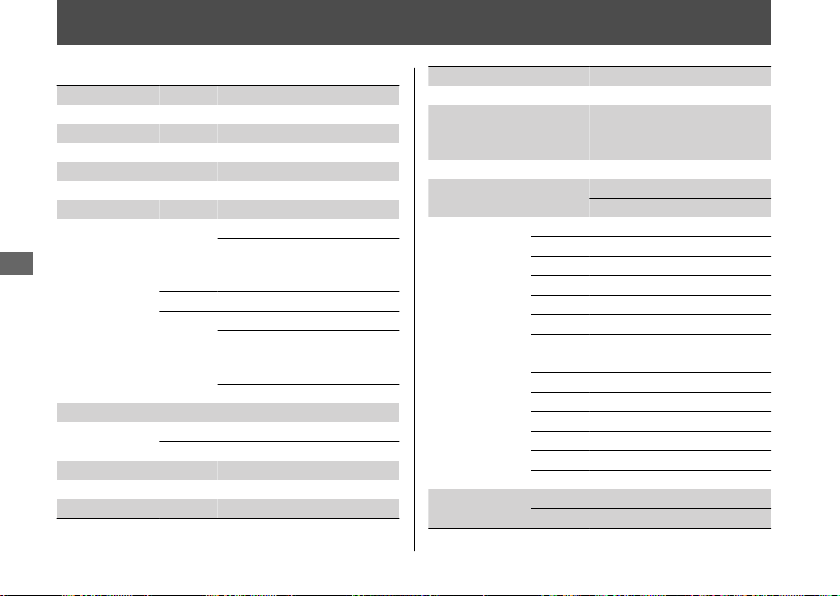
Specifications
■ Main Components
Overall length 87.8 in (2,230 mm)
Overall width 33.3 in (845 mm)
Overall height 53.1 in (1,350 mm)
Wheelbase 60.4 in (1,535 mm)
Minimum ground clearance 6.5 in (165 mm)
Caster angle 27° 00’
Trail 4.3 in (110 mm)
Curb weight
NC750X
49 STATE
478 lb (217 kg)
50 STATE
(meets
California)
481 lb (218 kg)
NC750XA
485 lb (220 kg)
NC750XD
49 STATE
505 lb (229 kg)
50 STATE
(meets
California)
507 lb (230 kg)
Canada 507 lb (230 kg)
Maximum weight capacity
*1
430 lb (195 kg)
Maximum
luggage weight
Luggage box 11.0 lb (5.0 kg)
Luggage box lid 4.5 lb (2.0 kg)
Passenger capacity Rider and 1 passenger
Minimum turning radius 9.84 ft (3.00 m)
Displacement 45.4 cu-in (745 cm
3
)
*1 : Including rider, passenger, all luggage, and accessories
Bore x stroke 3.03 x 3.15 in (77 x 80 mm)
Compression ratio 10.7 : 1
Fuel
Unleaded gasoline
Recommended: 86 PON or
higher
Tank capacity 3.73 US gal (14.1 L)
Battery
YTZ14S
12 V-11.2 Ah (10 HR)
Gear ratio
NC750X/XA
1st 2.812
2nd 1.894
3rd 1.454
4th 1.200
5th 1.033
6th 0.837
NC750XD
1st 2.666
2nd 1.904
3rd 1.454
4th 1.200
5th 1.033
6th 0.864
Reduction ratio
(primary / final)
NC750X/XA
1.731 / 2.529
NC750XD
1.921 / 2.294
Specifications
174
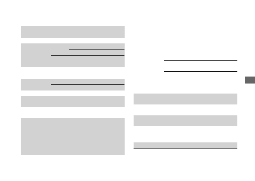
■ Service Data
Tire size
Front 120/70ZR17M/C(58W)
Rear 160/60ZR17M/C(69W)
Tire type Radial, tubeless
Recommended
Tire
Front
DUNLOP D609F
BRIDGESTONE BW-501 RADIAL G
Rear
DUNLOP D609
BRIDGESTONE BW-502 RADIAL G
Tire air pressure
Front 36 psi (250 kPa, 2.50 kgf/cm
2
)
Rear 42 psi (290 kPa, 2.90 kgf/cm
2
)
Minimum tread
depth
Front 0.06 in (1.5 mm)
Rear 0.08 in (2.0 mm)
Spark plug
(standard)
IFR6G-11K (NGK)
Spark plug gap
(non-
adjustable)
0.039 - 0.043 in (1.00 - 1.10 mm)
Idle speed
(non-
adjustable)
1,200 ± 100 rpm
Recommended
engine oil
API Service Classification SG or higher
except oils labeled as energy conserving or
resource conserving on the circular API
service label, SAE 10W-30, JASO T 903
standard MA, Pro Honda GN4 4-stroke oil
(USA & Canada) or Honda 4-stroke oil, or
an equivalent motorcycle oil
Engine oil
capacity
NC750X/XA
After draining 3.3 US qt (3.1 L)
After draining &
engine oil filter change
3.6 US qt (3.4 L)
After disassembly 3.9 US qt (3.7 L)
NC750XD
After draining 3.4 US qt (3.2 L)
After draining &
engine oil filter change
3.6 US qt (3.4 L)
After draining, engine
& clutch oil filter
change
3.6 US qt (3.4 L)
After disassembly 4.3 US qt (4.1 L)
Recommended
brake fluid
Honda DOT 4 Brake Fluid
Cooling system
capacity
1.79 US qt (1.69 L)
Recommended
coolant
Pro Honda HP Coolant
Recommended
drive chain
lubricant
Pro Honda HP Chain Lube or equivalent
Drive chain slack 1 3/16 - 1 9/16 in (30 - 40 mm)
Specifications
Specifications
175
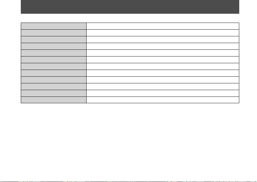
Information Record
VIN
Engine No.
Color Label & Code
Owner's Name
Address
City/State
Phone
Dealer's Name
Address
City/State
Phone
Service Manager
177

Index
A
ABS (Anti-lock Brake System)....................
... 12
ABS (Anti-lock Brake System)
Indicator .................................................. 48, 133
Accessories........................................................ 16
AT Mode ............................................................ 65
AT/MT Switch............................................. 53, 66
Authorized Manuals...................................... 168
B
Battery.......................................................... 85, 97
Brake Lever...................................................... 128
Brake Light Switch......................................... 115
Brakes
Fluid .................................................... 89, 113, 175
Pad Wear........................................................... 114
Parking Brake...................................................... 55
Braking ............................................................... 11
Bulb
Brake Light/Taillight ........................................ 146
Front Turn Signal ............................................. 147
Rear Turn Signal............................................... 147
C
Catalytic Converter........................................ 166
Clutch Oil Filter .............................................. 109
Clutch System................................................. 121
Color Label ........................................................ 84
Coolant............................................................. 111
Crankcase Breather ....................................... 126
D
D Mode .............................................................. 65
Drive Chain ............................................... 89, 117
Drive Chain Slider.......................................... 120
E
Electrical Trouble ........................................... 145
Emission Control Systems ........................... 162
Index
178

Engine
Number...........................................................
... 161
Oil ................................................................. 88, 105
Oil Filter.............................................................. 107
Overheats .......................................................... 131
Starting ................................................................. 58
Stop Switch................................... 51, 53, 58, 153
Stopping ............................................................ 153
Will Not Start .................................................... 130
Environment ................................................... 160
Equipment
Owner's Manual ................................................. 73
Tool Kit.................................................................. 73
F
Flooded Engine ................................................ 59
Fuel
Recommended................................................... 70
Tank Capacity ..................................................... 70
Fuses........................................................... 87, 148
G
Gasohol ............................................................ 167
Gasoline ............................................................. 69
H
Hazard Switch ............................................ 50, 52
Headlight......................................................... 146
Headlight Aim ................................................ 127
Headlight Dimmer Switch....................... 50, 52
Helmet Holder.................................................. 74
High Beam Indicator....................................... 48
High Coolant Temperature Indicator ......... 48
Honda Contacts ............................................. 171
Horn Button................................................ 50, 52
I
Ignition Cut-off System
Banking Sensor................................................. 154
Side Stand ......................................................... 116
Ignition Key..................................................... 152
Ignition Switch................................... 51, 58, 153
Indicators........................................................... 48
Information Record....................................... 177
Instruments ....................................................... 22
Instruments, Controls, &Other
Features ......................................................... 153
Index
179

L
Labels.................................................................... 8
Load Limits
........................................................ 17
Loading Guidelines.......................................... 17
Low Oil Pressure Indicator.................... 48, 132
Lower Cowl........................................................ 99
Luggage Box ..................................................... 71
M
Maintenance
Fundamentals ..................................................... 82
Importance .......................................................... 76
Record .................................................................. 81
Safety .................................................................... 77
Schedule............................................................... 78
Maximum Weight Limit ................................. 17
Modifications.................................................... 16
MT Mode ........................................................... 65
N
N-D Switch ........................................................ 53
Neutral Indicator ............................................. 48
O
Odometer ........................................................ 153
Oil
Engine.......................................................... 88, 105
Overheating .................................................... 131
Owner's Manual ............................................... 73
Oxygenated Fuels.......................................... 167
P
Parking ............................................................... 13
Parking Brake.................................................... 55
Parking Brake Indicator.................................. 49
Parking Brake Lever ........................................ 55
Parts Location................................................... 18
PGM-FI (Programmed Fuel Injection)
Malfunction Indicator Lamp (MIL).... 49, 132
Position Light ................................................. 146
Protective Apparel........................................... 10
R
Rear Seat............................................................ 69
Index
180

Recommended
Coolant..............................................................
... 91
Fuel........................................................................ 70
Oil .......................................................................... 88
Refueling............................................................ 69
Removal
Battery................................................................... 97
Clip......................................................................... 98
Lower Cowl.......................................................... 99
Maintenance Lid .............................................. 101
Repair Kit ......................................................... 137
Reporting Safety Defects............................. 173
Riding Precautions .......................................... 11
S
S Mode ............................................................... 65
Safety Guidelines ............................................... 3
Safety Labels ....................................................... 8
Safety Precautions........................................... 10
Shift Switch ....................................................... 52
Shifting Gears ................................................... 61
Side Stand ....................................................... 116
Side Stand Ignition Cut-off System .......... 116
Spark Plugs ..................................................... 102
Specifications.................................................. 174
Start Button.......................................... 51, 53, 58
Starting the Engine ......................................... 58
Steering Lock .................................................... 54
Stopping Engine ............................................ 153
Storage
Equipment ........................................................... 71
Helmet .................................................................. 72
Luggage Box ....................................................... 71
Owner’s Manual ................................................. 73
Tool Kit.................................................................. 73
Storing Your Vehicle..................................... 159
Switches ............................................................. 50
T
Throttle ............................................................ 124
Tires
Air Pressure ......................................................... 92
Puncture............................................................. 137
Replacing .................................................... 92, 137
Tool kit ............................................................... 73
Torque Control Indicator............................... 49
Torque Control OFF Indicator....................... 49
Torque Control Switch ............................. 50, 52
Index
181

Transporting ................................................... 160
Tripmeter......................................................
... 153
Troubleshooting ............................................ 129
Turn Signal Indicators .................................... 48
V
Vehicle Identification Number ................... 161
W
Warning Indicators On................................. 132
Warranty Coverage and Service ................ 169
Washing ........................................................... 155
Weight Limit............................................. 17, 174
Wheels
Front Removal .................................................. 138
Rear Removal.................................................... 141
Index
182