
www.lg.com
OWNER’S MANUAL
PLASMA TV
Please read this manual carefully before operating your set and retain it
for future reference.
P/NO : MFL67468602 (1207-REV05)
42PM4700
50PM4700
50PM9700
60PM9700
50PM6700
60PM6700
2
ENG
ENGLISH
IMPORTANT SAFETY INSTRUCTIONS
WARNING/CAUTION
RISK OF ELECTRIC SHOCK
DO NOT OPEN
TO REDUCE THE RISK OF ELECTRIC SHOCK
DO NOT REMOVE COVER (OR BACK). NO
USER SERVICEABLE PARTS INSIDE. REFER
TO QUALIFIED SERVICE PERSONNEL.
WARNING/CAUTION
RISK OF ELECTRIC SHOCK
DO NOT OPEN
The lightning flash with arrowhead
symbol, within an equilateral triangle,
is intended to alert the user to the
presence of uninsulated “dangerous voltage”
within the product’s enclosure that may be of
sufficient magnitude to constitute a risk of
electric shock to persons.
WARNING/CAUTION
RISK OF ELECTRIC SHOCK
DO NOT OPEN
The exclamation point within an
equilateral triangle is intended to alert
the user to the presence of important
operating and maintenance (servicing)
instructions in the literature accompanying
the appliance.
WARNING/CAUTION
- TO REDUCE THE RISK OF FIRE AND
ELECTRIC SHOCK, DO NOT EXPOSE THIS
PRODUCT TO RAIN OR MOISTURE.
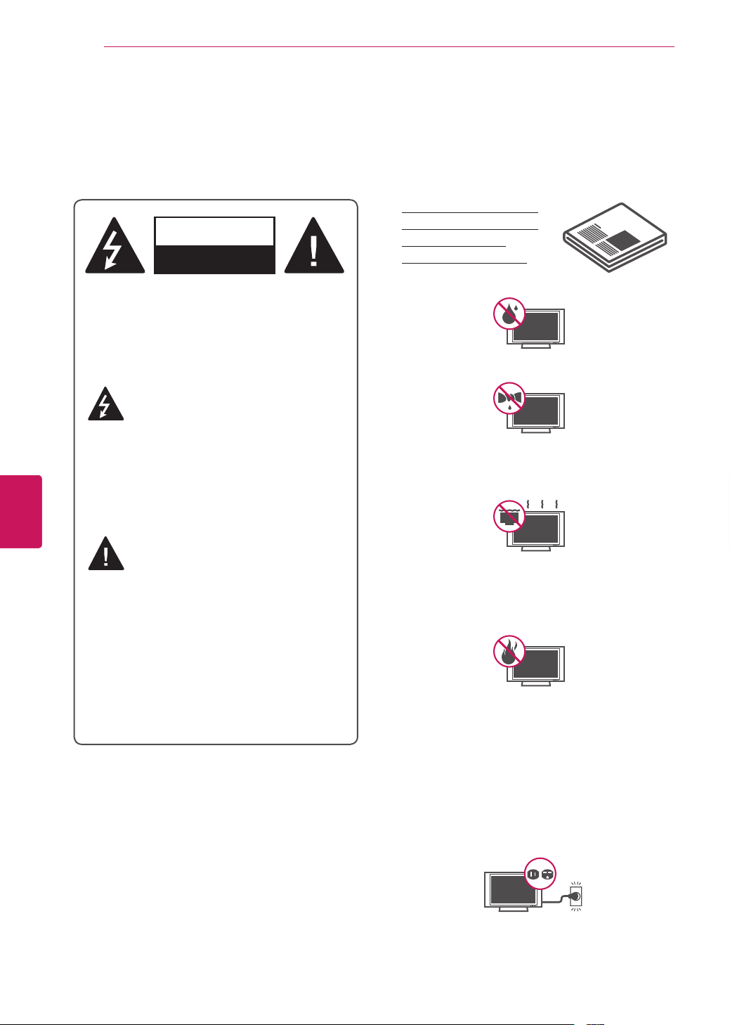
Do not use this apparatus near water.
Short-circuit
Breaker
Power Supply
Clean only with a dry cloth.
Short-circuit
Breaker
Power Supply
Do not block any ventilation openings. Install
in accordance with the manufacturer’s
instructions.
Short-circuit
Breaker
Power Supply
Do not install near any heat sources such
as radiators, heat registers, stoves, or other
apparatus (including amplifiers) that produce
heat.
Short-circuit
Breaker
Power Supply
Do not defeat the safety purpose of the
polarized or grounding-type plug. A polarized
plug has two blades with one wider than the
other. A grounding type plug has two blades
and a third grounding prong. The wide blade
or the third prong are provided for your safety.
If the provided plug does not fit into your
outlet, consult an electrician for replacement
of the obsolete outlet (Can differ by country).
Short-circuit
Breaker
Power Supply
IMPORTANT SAFETY INSTRUCTIONS
Always comply with the following precautions to avoid dangerous situations and ensure peak performance
of your product.
Read these instructions.
Keep these instructions.
Heed all warnings.
Follow all instructions.
Short-circuit
Breaker
Power Supply
WARNING
: This product contains chemicals
known to the State of California to cause cancer
and birth defects or other reproductive harm.
Wash hands after handling.
3
ENG
ENGLISH
IMPORTANT SAFETY INSTRUCTIONS
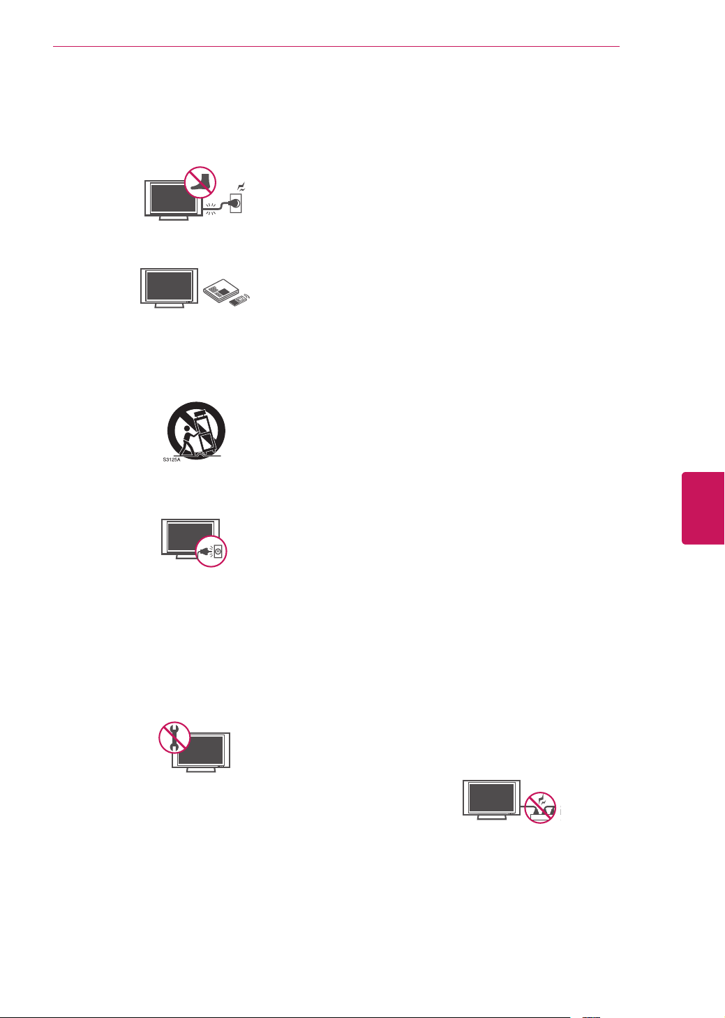
Protect the power cord from being walked on
or pinched particularly at plugs, convenience
receptacles, and the point where they exit
from the apparatus.
Short-circuit
Breaker
Power Supply
Only use attachments/accessories specified
by the manufacturer.
Short-circuit
Breaker
Power Supply
Use only with a cart, stand, tripod, bracket,
or table specified by the manufacturer, or
sold with the apparatus. When a cart is used,
use caution when moving the cart/apparatus
combination to avoid injury from tip-over.
Short-circuit
Breaker
Power Supply
Unplug this apparatus during lightning
storms or when unused for long periods of
time.
Short-circuit
Breaker
Power Supply
Refer all servicing to qualified service
personnel. Servicing is required when
the apparatus has been damaged in any
way, such as power-supply cord or plug is
damaged, liquid has been spilled or objects
have fallen into the apparatus, the apparatus
has been exposed to rain or moisture, does
not operate normally, or has been dropped.
Short-circuit
Breaker
Power Supply
Do not stick metal objects or any other
conductive material into the power cord. Do
not touch the end of the power cord while it
is plugged in.
Keep the packing anti-moisture material or
vinyl packing out of the reach of children.
Anti-moisture material is harmful if
swallowed. If swallowed by mistake, force
the patient to vomit and visit the nearest
hospital. Additionally, vinyl packing can
cause suffocation. Keep it out of the reach of
children.
CAUTION concerning the Power Cord
(Can differ by country):
It is recommended that appliances be
placed upon a dedicated circuit; that is, a
single outlet circuit which powers only that
appliance and has no additional outlets or
branch circuits. Check the specification page
of this owner’s manual to be certain. Do not
connect too many appliances to the same
AC power outlet as this could result in fire or
electric shock. Do not overload wall outlets.
Overloaded wall outlets, loose or damaged
wall outlets, extension cords, frayed power
cords, or damaged or cracked wire insulation
are dangerous. Any of these conditions could
result in electric shock or fire. Periodically
examine the cord of your appliance, and
if its appearance indicates damage or
deterioration, unplug it, discontinue use of
the appliance, and have the cord replaced
with an exact replacement part by an
authorized service. Protect the power cord
from physical or mechanical abuse, such as
being twisted, kinked, pinched, closed in a
door, or walked upon. Pay particular attention
to plugs, wall outlets, and the point where
the cord exits the appliance. Do not move
the TV with the power cord plugged in. Do
not use a damaged or loose power cord. Be
sure do grasp the plug when unplugging the
power cord. Do not pull on the power cord
to unplug the TV.
Short-circuit
Breaker
Power Supply
4
ENG
ENGLISH
IMPORTANT SAFETY INSTRUCTIONS
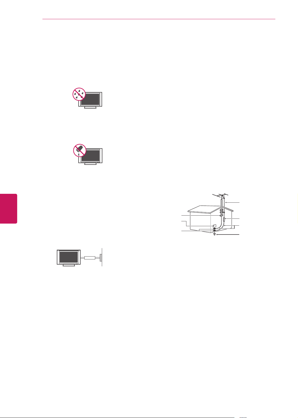
Warning
- To reduce the risk of fire or
electrical shock, do not expose this product
to rain, moisture or other liquids. Do not
touch the TV with wet hands. Do not install
this product near flammable objects such
as gasoline or candles, or expose the TV to
direct air conditioning.
Short-circuit
Breaker
Power Supply
Do not expose to dripping or splashing and
do not place objects filled with liquids, such
as vases, cups, etc. on or over the apparatus
(e.g. on shelves above the unit).
Short-circuit
Breaker
Power Supply
Grounding
(Except for devices which are not grounded.)
Ensure that you connect the earth ground
wire to prevent possible electric shock
(i.e. a TV with a three-prong grounded AC
plug must be connected to a three-prong
grounded AC outlet). If grounding methods
are not possible, have a qualified electrician
install a separate circuit breaker. Do not try to
ground the unit by connecting it to telephone
wires, lightening rods, or gas pipes.
Short-circuit
Breaker
Power Supply
DISCONNECTING DEVICE FROM THE MAIN
POWER
Mains plug is the disconnecting device. The
plug must remain readily operable.
As long as this unit is connected to the AC
wall outlet, it is not disconnected from the
AC power source even if the unit is turned
off.
Do not attempt to modify this product in any
way without written authorization from LG
Electronics. Unauthorized modification could
void the user’s authority to operate this
product.
ANTENNAS Outdoor antenna grounding
(Can differ by country):
If an outdoor antenna is installed, follow
the precautions below. An outdoor antenna
system should not be located in the vicinity
of overhead power lines or other electric light
or power circuits, or where it can come in
contact with such power lines or circuits as
death or serious injury can occur. Be sure the
antenna system is grounded so as to provide
some protection against voltage surges
and built-up static charges. Section 810 of
the National Electrical Code (NEC) in the
U.S.A. provides information with respect to
proper grounding of the mast and supporting
structure, grounding of the lead-in wire to
an antenna discharge unit, size of grounding
conductors, location of antenna discharge
unit, connection to grounding electrodes and
requirements for the grounding electrode.
Antenna grounding according to the National
Electrical Code, ANSI/NFPA 70
Short-circuit
Breaker
Power Supply
NEC: National Electrical Code
Ground Clamp
Antenna Lead in Wire
Antenna Discharge Unit
(NEC Section 810-20)
Grounding Conductor
(NEC Section 810-21)
Power Service Grounding
Electrode System
(NEC Art 250, Part H)
Electric Service
Equipment
Ground Clamp
Cleaning
When cleaning, unplug the power cord and
wipe gently with a soft cloth to prevent
scratching. Do not spray water or other
liquids directly on the TV as electric shock
may occur. Do not clean with chemicals
such as alcohol, thinners or benzine.
Moving
Make sure the product is turned off,
unplugged and all cables have been
removed. It may take 2 or more people to
carry larger TVs. Do not press or put stress
on the front panel of the TV.
5
ENG
ENGLISH
IMPORTANT SAFETY INSTRUCTIONS
Ventilation
Install your TV where there is proper
ventilation. Do not install in a confined
space such as a bookcase. Do not cover the
product with cloth or other materials while
plugged. Do not install in excessively dusty
places.
If you smell smoke or other odors coming
from the TV, unplug the power cord and
contact an authorized service center.
Do not press strongly upon the panel with a
hand or a sharp object such as a nail, pencil
or pen, or make a scratch on it.
Keep the product away from direct sunlight.
Short-circuit
Breaker
Power Supply
Never touch this apparatus or antenna during
a thunder or lightning storm.
When mounting a TV on the wall, make sure
not to install the TV by hanging the power
and signal cables on the back of the TV.
Do not allow an impact shock or any objects
to fall into the product, and do not drop
anything onto the screen.
Dot Defect
The Plasma or LCD panel is a high
technology product with resolution of two
million to six million pixels. In a very few
cases, you could see fine dots on the screen
while you’re viewing the TV. Those dots
are deactivated pixels and do not affect the
performance and reliability of the TV.
Generated Sound
“Cracking” noise: A cracking noise that
occurs when watching or turning off the TV
is generated by plastic thermal contraction
due to temperature and humidity. This noise
is common for products where thermal
deformation is required.
Electrical circuit humming/panel buzzing: A
low level noise is generated from a high-
speed switching circuit, which supplies a
large amount of current to operate a product.
It varies depending on the product.
This generated sound does not affect the
performance and reliability of the product.
Take care not to touch the ventilation
openings. When watching the TV for a long
period, the ventilation openings may become
hot. This does not affect the performance of
the product or cause defects in the product.
Preventing “Image burn” or “Burn-in” on your TV screen
If a fixed image displays on the TV screen
for a long period of time, it will be imprinted
and become a permanent disfigurement on
the screen. This is “image burn” or “burn-in”
and not covered by the warranty.
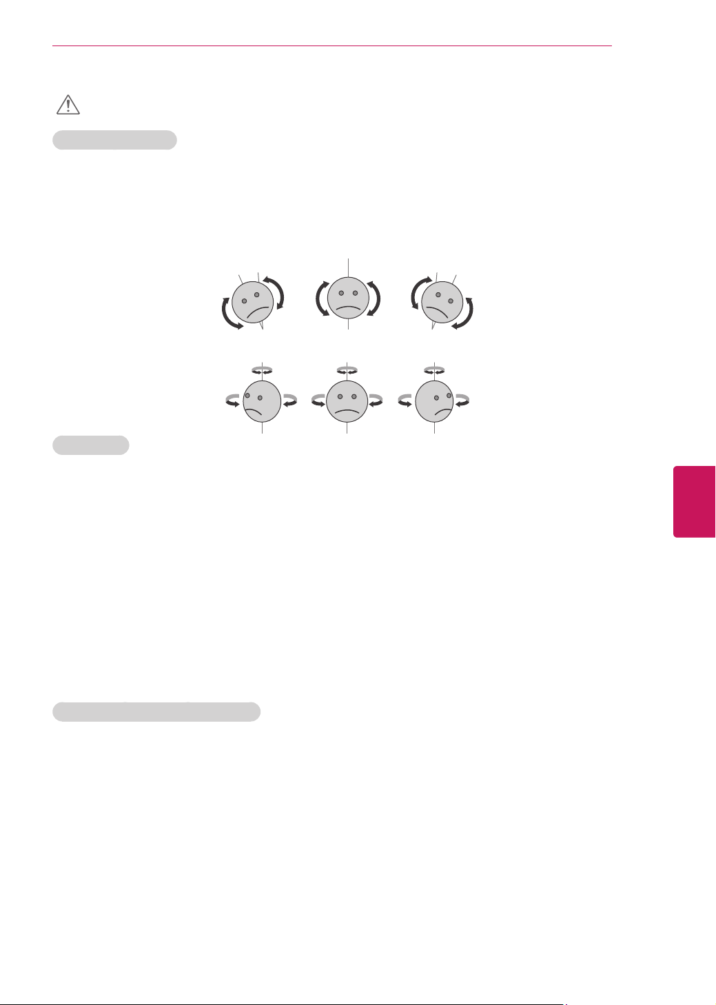
If the aspect ratio of the TV is set to 4:3 for
a long period of time, image burn may occur
on the letterboxed area of the screen.
Avoid displaying a fixed image on the TV
screen for a long period of time (2 or more
hours for LCD, 1 or more hours for the
Plasma TV) to prevent image burn.

6
ENG
ENGLISH
IMPORTANT SAFETY INSTRUCTIONS
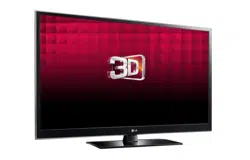
Viewing 3D Imaging (For 3D models)
WARNING
Viewing Environment
Viewing Time
- When watching 3D contents, take 5 - 15 minute breaks every hour. Viewing 3D contents for a long
period of time may cause headache, dizziness, fatigue or eye strain.
Those that have a photosensitive seizure or chronic illness
Some users may experience a seizure or other abnormal symptoms when they are exposed to a
flashing light or particular pattern from 3D contents.
Do not watch 3D videos if you feel nausea, are pregnant and/ or have a chronic illness such as
epilepsy, cardiac disorder, or blood pressure disease, etc.
3D Contents are not recommended to those who suffer from stereo blindness or stereo anomaly.
Double images or discomfort in viewing may be experienced.
If you have strabismus (cross-eyed), amblyopia (weak eyesight) or astigmatism, you may have trouble
sensing depth and easily feel fatigue due to double images. It is advised to take frequent breaks than
the average adult.
If your eyesight varies between your right and left eye, revise your eyesight prior to watching 3D
contents.
Symptoms which require discontinuation or refraining from watching 3D contents
Do not watch 3D contents when you feel fatigue from lack of sleep, overwork or drinking.
When these symptoms are experienced, stop using/watching 3D contents and get enough rest until
the symptom subsides.
- Consult your doctor when the symptoms persist. Symptoms may include headache, eyeball pain,
dizziness, nausea, palpitation, blurriness, discomfort, double image, visual inconvenience or fatigue.
7
ENG
ENGLISH
IMPORTANT SAFETY INSTRUCTIONS
CAUTION
Viewing Environment
Viewing Distance
- Maintain a distance of at least twice the screen diagonal length when watching 3D contents. If you
feel discomfort in viewing 3D contents, move further away from the TV.
Viewing Position (Only for SG Mode)
- Face the center of the screen at eye level with the head looking straight ahead. Otherwise, you may
not be able to view 3D contents properly.
Viewing Age
Infants / Children
- Usage/ Viewing 3D contents for children under the age of 5 are prohibited.
- Children under the age of 10 may overreact and become overly excited because their vision is in
development (for example: trying to touch the screen or trying to jump into it. Special monitoring and
extra attention is required for children watching 3D contents.
- Children have greater binocular disparity of 3D presentations than adults because the distance
between the eyes is shorter than one of adults. Therefore they will perceive more stereoscopic depth
compared to adults for the same 3D image.
Teenagers
- Teenagers under the age of 19 may be stimulated to light coming from 3D videos. Advise them not to
watch 3D videos for a long time when they are tired.
Elderly
- The elderly may perceive less of a 3D effect than the youth. Do not sit closer to the TV than the
recommended distance.
Cautions when using the 3D glasses
Make sure to use LG 3D glasses. Otherwise, you may not be able to view 3D videos properly.
Do not use 3D glasses instead of your normal glasses, sunglasses or protective goggles.
Using modified 3D glasses may cause eye strain or image distortion.
Do not keep your 3D glasses in extremely high or low temperatures. It will cause deformation.
The 3D glasses are fragile and are easy to be scratched. Always use a soft, clean piece of cloth when
wiping the lenses. Do not scratch the lenses of the 3D glasses with sharp objects or clean/wipe them
with chemicals.
When watching 3D videos under fluorescent lights or with three wave length lamps, you may
experience the screen blinking. When this occurs, turn the light off or turn it down. (Only for SG
mode)
Other electronic or communication devices should be turned off or put away from the TV because it
can cause interference and prevent the 3D function from working properly. (Only for SG mode)
When you watch TV lying down, 3D images may look darker or invisible. (Only for SG mode)

8
ENG
ENGLISH
LICENSES / OPEN SOURCE SOFTWARE NOTICE
LICENSES
Supported licenses may differ by model. For more information about licenses, visit www.lg.com.
Manufactured under license from Dolby Laboratories. “Dolby” and the double-D
symbol are trademarks of Dolby Laboratories.
HDMI, the HDMI logo and High-Definition Multimedia Interface are trademarks or
registered trademarks of HDMI Licensing LLC.
ABOUT DIVX VIDEO: DivX
®
is a digital video format created by DivX, LLC, a
subsidiary of Rovi Corporation. This is an official DivX Certified
®
device that plays
DivX video. Visit divx.com for more information and software tools to convert your
files into DivX video.
ABOUT DIVX VIDEO-ON-DEMAND: This DivX Certified
®
device must be registered
in order to play purchased DivX Video-on-Demand (VOD) movies. To obtain your
registration code, locate the DivX VOD section in your device setup menu. Go to
vod.divx.com for more information on how to complete your registration.
“DivX Certified
®
to play DivX
®
video up to HD 1080p, including premium content.”
“DivX
®
, DivX Certified
®
and associated logos are trademarks of Rovi Corporation
or its subsidiaries and are used under license.”
“Covered by one or more of the following U.S. patents:
7,295,673; 7,460,668; 7,515,710; 7,519,274”
Manufactured under license under U.S. Patent Nos: 5,956,674; 5,974,380;
6,487,535 & other U.S. and worldwide patents issued & pending. DTS, the Symbol
& DTS and the Symbol together are registered trademarks & DTS 2.0+Digital
Out is a trademark of DTS, Inc. Product includes software. © DTS, Inc. All Rights
Reserved.
OPEN SOURCE SOFTWARE NOTICE
To obtain the source code under GPL, LGPL, MPL and other open source licenses, that is contained in this
product, please visit http://opensource.lge.com.
In addition to the source code, all referred license terms, warranty disclaimers and copyright notices are
available for download.
LG Electronics will also provide open source code to you on CD-ROM for a charge covering the cost of
performing such distribution (such as the cost of media, shipping and handling) upon email request to
[email protected]. This offer is valid for three (3) years from the date on which you purchased the
product.

9
ENG
ENGLISH
TABLE OF CONTENTS
TABLE OF CONTENTS
2 IMPORTANT SAFETY INSTRUCTIONS
6 Viewing 3D Imaging (For 3D models)
8 LICENSES
8 OPEN SOURCE SOFTWARE NOTICE
9 TABLE OF CONTENTS
10 INSTALLATION PROCEDURE
10 ASSEMBLING AND PREPARING
10 Unpacking
14 Optional Extras
15 Parts and buttons
16 Lifting and moving the TV
17 Setting up the TV
17 - Attaching the stand
19 - Attaching the protection cover
19 - Tidying cables
20 - Mounting on a table
21 - Mounting on a wall
22 MAKING CONNECTIONS
22 Connecting to an antenna or cable
23 Connecting to a HD receiver, DVD, or
VCR player
23 - HDMI Connection
24 - DVI to HDMI Connection
25 - Component Connection
26 - Composite Connection
27 Connecting to a PC
27 - HDMI Connection, DVI to
HDMI Connection or RGB Connection
29 Connecting to an Audio System
29 - Digital Optical Audio Connection
30 Connecting to a USB
31 REMOTE CONTROL
33 Magic Remote Control Functions
34 - Registering Magic Remote Control
34 - How to use Magic Remote Control
34 - Precautions to Take when Using the
Magic Remote Control
35 WATCHING TV
35 Turning the TV on for the first time
36 USING THE USER GUIDE
37 TROUBLESHOOTING
37 EXTERNAL CONTROL DEVICE SETUP
38 SPECIFICATIONS
42 MAINTENANCE
42 Cleaning Your TV
42 - Screen, frame, Cabinet and stand
42 - Power cord
NOTE
Image shown may differ from your TV.
Your TV’s OSD (On Screen Display) may
differ slightly from that shown in this manual.
The available menus and options may differ
from the input source or product model that
you are using.
New features may be added to this TV in the
future.
10
ENG
ENGLISH
ASSEMBLING AND PREPARING
INSTALLATION PROCEDURE
1
Open the package and make sure all the accessories are included.
2
Attach the stand to the TV set.
3
Connect an external device to the TV set.
4
Make sure the network connection is available.
You can use the TV network functions only when the network connection is made.
ASSEMBLING AND PREPARING
Unpacking
Check your product box for the following items. If there are any missing accessories, contact the local
dealer where you purchased your product. The illustrations in this manual may differ from the actual
product and item.
NOTE
The items supplied with your product may vary depending on the model.
Product specifications or contents of this manual may be changed without prior notice due to
upgrade of product functions.
CAUTION
Do not use any unapproved items to ensure the safety and product life span.
Any damages or injuries by using unapproved items are not covered by the warranty.
In case of some model, the thin film on screen is a part of TV, So don’t take it off.
11
ENG
ENGLISH
ASSEMBLING AND PREPARING
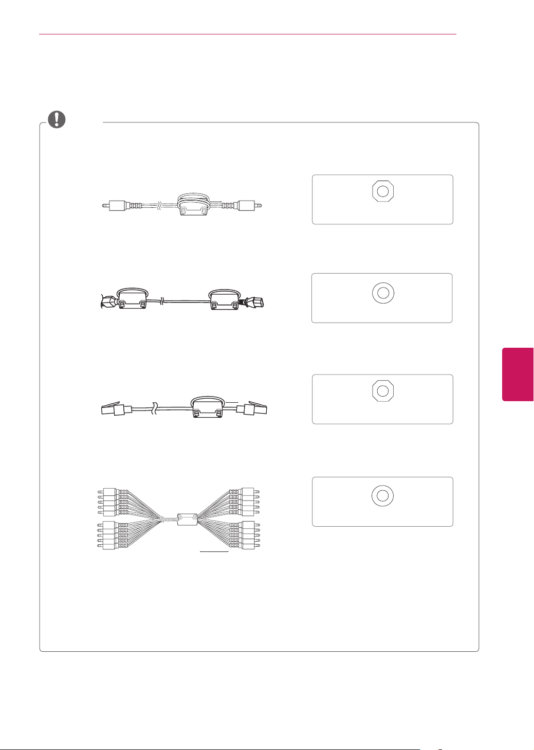
NOTE
How to use the ferrite core
1 Use the ferrite core to reduce the electromagnetic interference in the PC audio cable.
Wind the PC audio cable on the ferrite core thrice. Place the ferrite core close to the TV.
[to an External device] [to the TV]
[Figure 1]
[Cross Section of Ferrite Core]
10 mm (+/-5 mm)
2 Use the ferrite core to reduce the electromagnetic interference in the power cable.
Wind the power cable on the ferrite core once. Place the ferrite core close to the TV and wall plug.
[to a wall plug] [to the TV]
[Figure 2]
[Cross Section of Ferrite Core]
3 Use the ferrite core to reduce the electromagnetic interference in the LAN cable. Wind the
LAN cable once on the ferrite core. Place the ferrite core close to the TV.
[to an External device] [to the TV]
[Figure 3]
[Cross Section of Ferrite Core]
10 mm (+/-5 mm)
4 Use the ferrite core to reduce the electromagnetic interference in the component Y, Pb, Pr, L, R
cable. Place the ferrite core close to the TV.
[to an External device] [to the TV]
[Figure 4]
[Cross Section of Ferrite Core]
10 mm (+/-5 mm)
- If there is one ferrite core, follow as shown in Figure 1.
- If there are three ferrite cores, follow as shown in Figures 1 and 2.
- If there are four ferrite cores, follow as shown in Figures 1, 2 and 3.
- If there are five ferrite cores, follow as shown in Figures 1, 2, 3 and 4.
12
ENG
ENGLISH
ASSEMBLING AND PREPARING
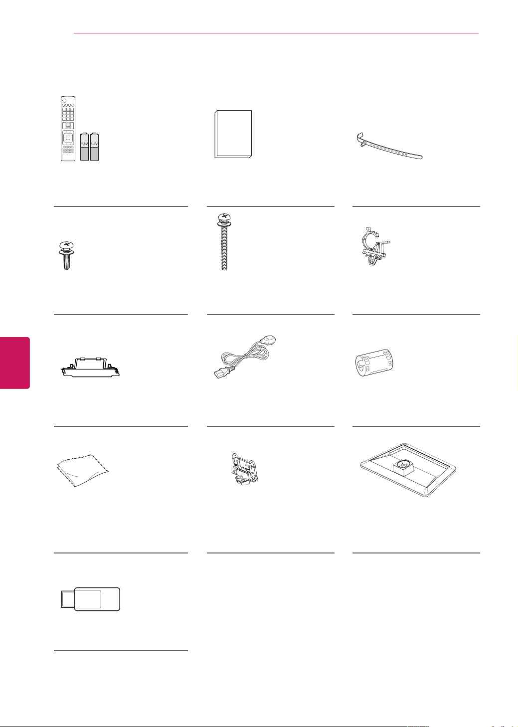
For PM4700, PM6700-UB series
Remote control,
Batteries (AAA)
(See p.31)
Owner’s manual Cable holder
(See p.19)
Stand Screws
3 EA, M5 x 16
(See p.17)
Stand Screws
4 EA, M4 x 30
(See p.17)
Power Cord holder
(See p.19)
Protection cover
(See p.19)
Power Cord Ferrite core
(Depending on model)
(See p.11)
Polishing cloth
(Depending on model)
Use this to remove dust from
the cabinet.
Stand Body
(See p.17)
Stand Base
(See p.17)
Wi-Fi dongle
(For PM4700 series)
FREEZE
RATIO
L/R SELECT
ENTER
BACK
EXIT
Q.MENU
INFO
MENU
CHVOL
P
A
G
E
FAV
3D
MUTE
1 2 3
4 5 6
7 8
0
9
MARK
LIST
FLASHBK
ENERGY
SAVING
TV
AV MODE
INPUT
13
ENG
ENGLISH
ASSEMBLING AND PREPARING
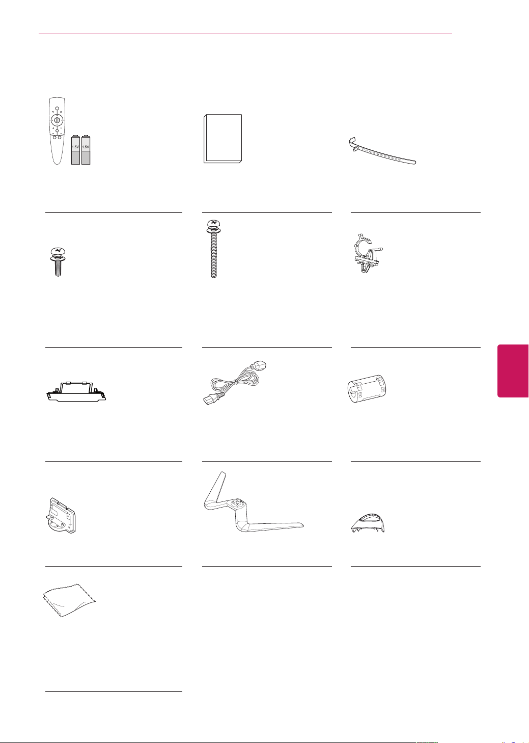
Magic Remote Control,
Batteries (AA)
(See p.33)
Owner’s manual Cable holder
(See p.19)
Stand Screws
M5 x 16
The number of screws may
differ depending on the model.
(See p.18)
Stand Screws
4 EA, M4 x 30
(See p.18)
Power Cord holder
(See p.19)
Protection cover
(See p.19)
Power Cord Ferrite core
(Depending on model)
(See p.11)
Stand Body
(See p.18)
Stand Base
(See p.18)
Cable management
(See p.18)
Polishing cloth
(Depending on model)
Use this to remove dust from
the cabinet.
For PM9700, PM6700-UD series
14
ENG
ENGLISH
ASSEMBLING AND PREPARING
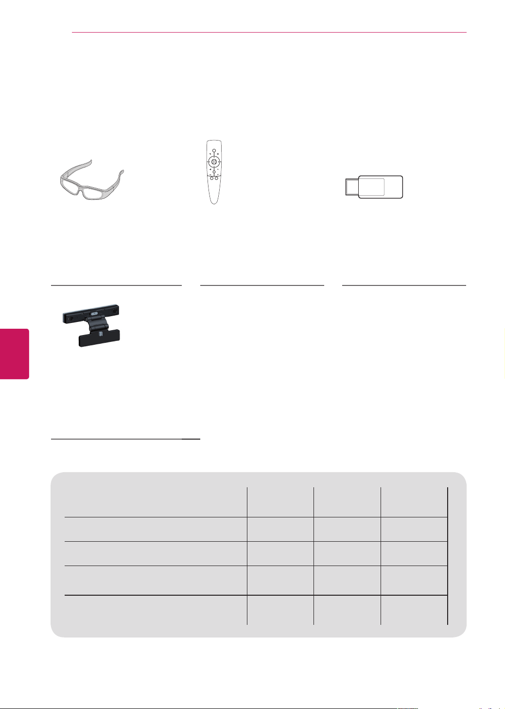
Optional Extras
Optional extras can be changed or modified for quality improvement without any notification.
Contact your dealer to buy these items.
These devices only work with certain models.
Compatibility
PM4700 PM6700 PM9700
AG-S3**
3D Glasses
• • •
AN-MR300
Magic Remote Control
• • •
AN-WF100
Wireless LAN for Broadband/
DLNA Adaptor
•
AN-VC***
Video Call Camera
• • •
AG-S3**
3D Glasses
The model name or
design may be changed
manufacturer’s circumstances
or policies.
AN-MR300
Magic Remote Control
AN-WF100
Wireless LAN for Broadband/
DLNA Adaptor
AN-VC***
Video Call Camera
The model name or
design may be changed
manufacturer’s circumstances
or policies.
15
ENG
ENGLISH
ASSEMBLING AND PREPARING
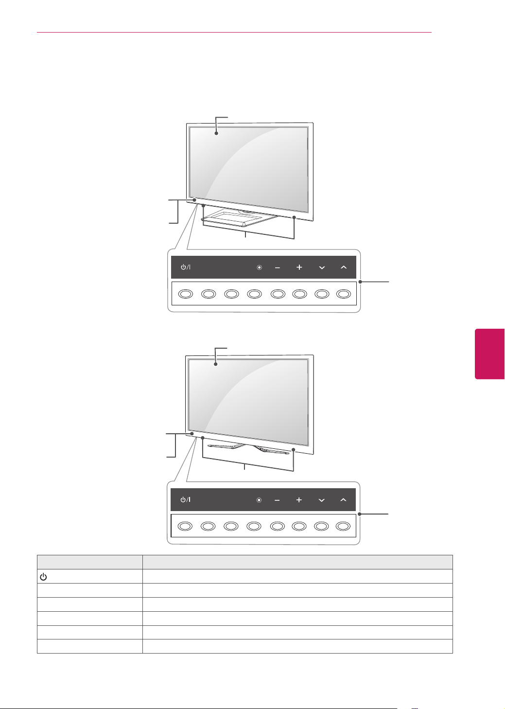
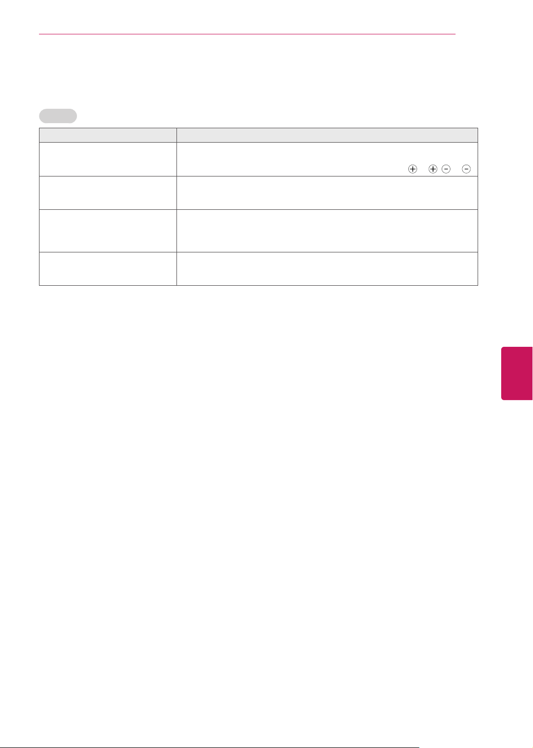
Parts and buttons
Button Description
/
I
Turns the power on or off.
INPUT Changes the input source.
SETTINGS Accesses the main menus, or saves your input and exits the menus.
OK
⊙
Selects the highlighted menu option or confirms an input.
- + Adjusts the volume level.
v
^
Scrolls through the saved channels.
1 Intelligent sensor - Adjusts the image quality and brightness based on the surrounding environment.
For PM4700, PM6700-UB series
SETTINGS
INPUT
OK
Screen
Buttons
Speakers
Remote control and
intelligent sensors
1
Power indicator
SETTINGS
INPUT
OK
For PM9700, PM6700-UD series
Remote control and
intelligent sensors
1
Screen
Buttons
Speakers
Power indicator
16
ENG
ENGLISH
ASSEMBLING AND PREPARING
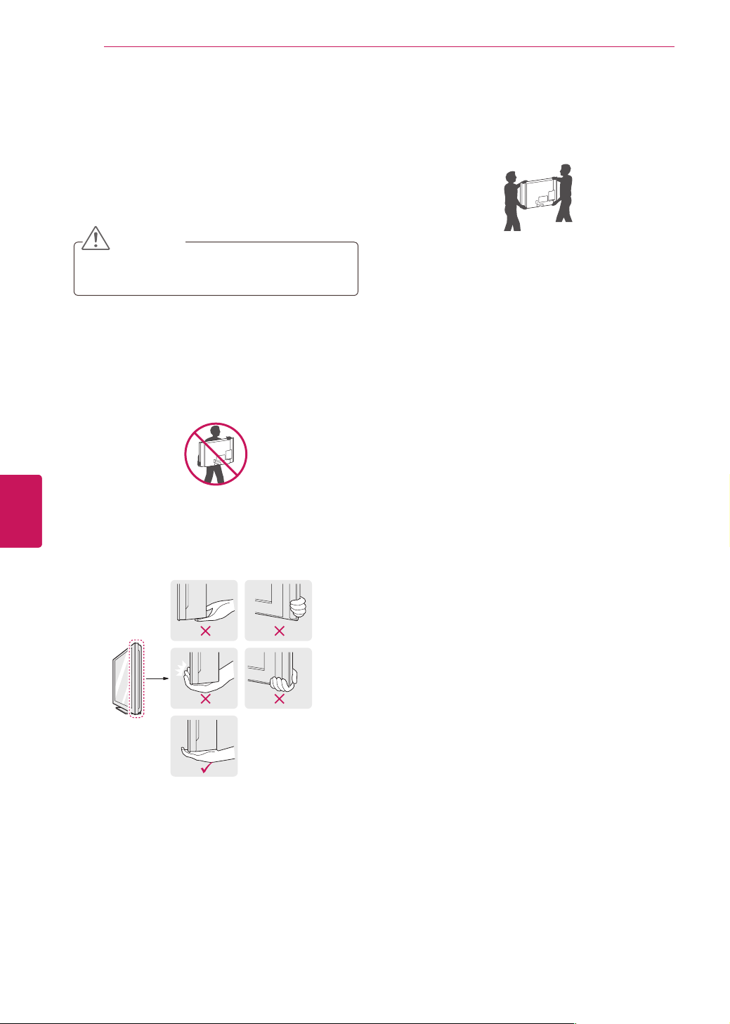
Lifting and moving the TV
When moving or lifting the TV, read the following
to prevent the TV from being scratched or
damaged and for safe transportation regardless of
its type and size.
CAUTION
Avoid touching the screen at all times, as
this may result in damage to the screen.
It is recommended to move the TV in the
box or packing material that the TV originally
came in.
Before moving or lifting the TV, disconnect
the power cord and all cables.
When holding the TV, the screen should face
away from you to avoid damage.
Hold the top and bottom of the TV frame
firmly. Make sure not to hold the transparent
part, speaker, or speaker grill area.
When transporting a large TV, there should
be at least 2 people.
When transporting the TV by hand, hold the
TV as shown in the following illustration.
When transporting the TV, do not expose the
TV to jolts or excessive vibration.
When transporting the TV, keep the TV
upright, never turn the TV on its side or tilt
towards the left or right.
17
ENG
ENGLISH
ASSEMBLING AND PREPARING
Setting up the TV
Put your TV on a pedestal stand and mount the TV on a table or wall.
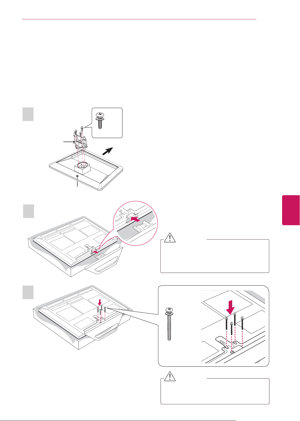
Attaching the stand
If you are not mounting the TV to a wall, use the following instructions to attach the stand.
For PM4700, PM6700-UB series
1
2
3
Front
M5 x 16
3 EA
CAUTION
When attaching the stand to the TV
set, place the screen facing down on a
cushioned table or flat surface to protect
the screen from scratches.
CAUTION
Tighten the screws firmly to prevent
the TV from tilting forward. Do not over
tighten.
M4 x 30
4 EA
Stand Body
Stand Base
18
ENG
ENGLISH
ASSEMBLING AND PREPARING
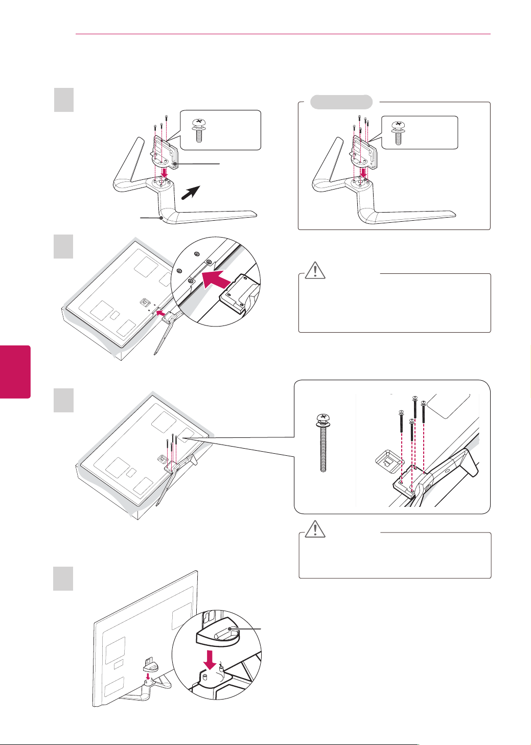
CAUTION
Tighten the screws firmly to prevent
the TV from tilting forward. Do not over
tighten.
CAUTION
When attaching the stand to the TV
set, place the screen facing down on a
cushioned table or flat surface to protect
the screen from scratches.
For PM9700/ PM6700-UD series
4
3
M4 x 30
4 EA
2
Cable management
1
Front
M5 x 16
3 EA
M5 x 16
5 EA
Stand Body
Stand Base
For 60 inches
19
ENG
ENGLISH
ASSEMBLING AND PREPARING
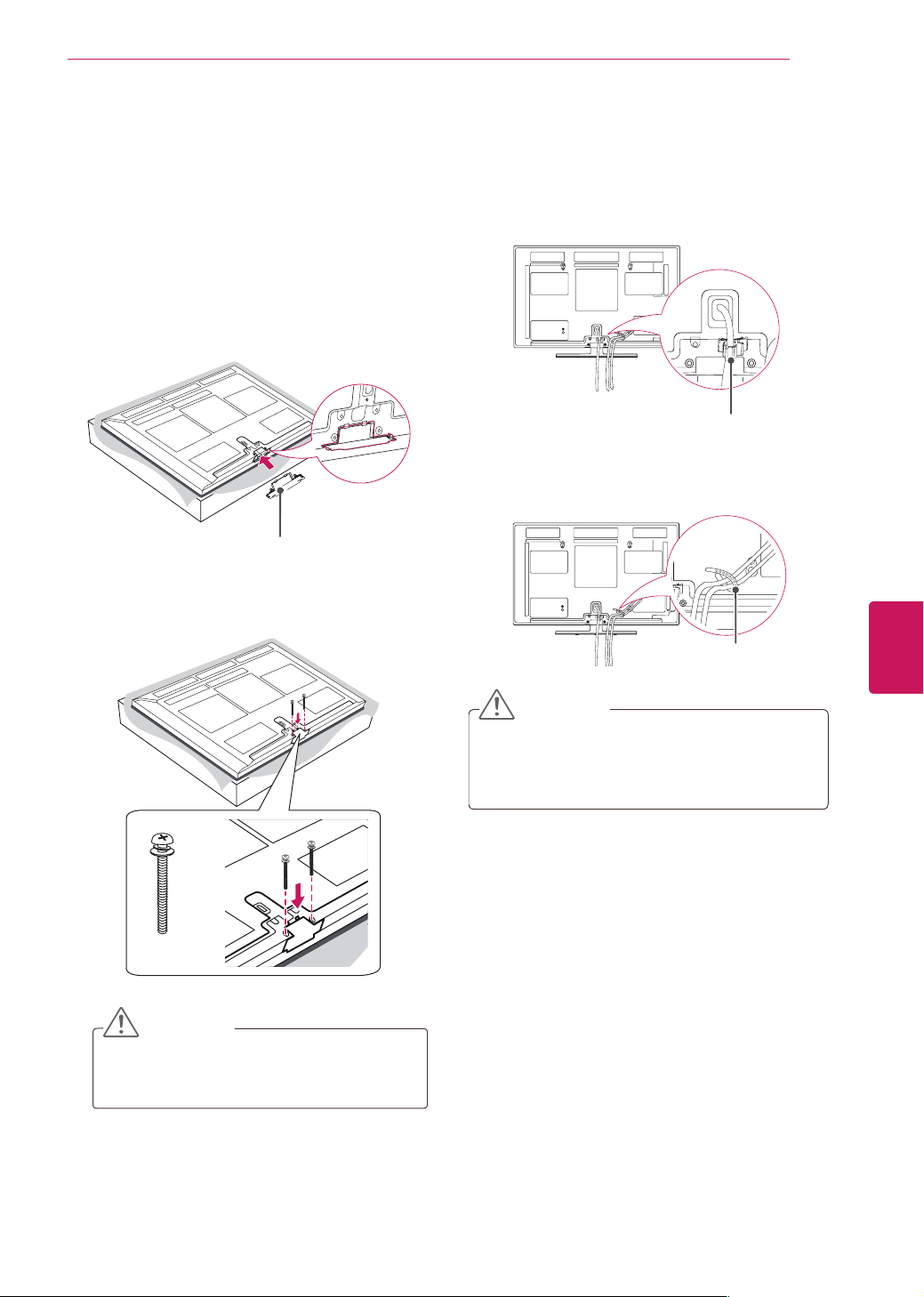
Attaching the protection cover
1
Remove the stand before installing the TV
on a wall mount by performing the stand
attachment in reverse.
After removing the stand, push the supplied
protection cover into the opening at the bottom
of the TV until it locks in place.
This will protect the opening from accumulating
dust and dirt.
Protection cover
2
Secure the TV and the protection cover with
the 2 screws.
M4 x 30
2 EA
CAUTION
Tighten the screws firmly to prevent
the TV from tilting forward. Do not over
tighten.
Tidying cables
1
Install the power cord holder and power cord.
It will help prevent the power cable from being
removed by accident.
Power cord holder
2
Gather and bind the cables with the cable
holder.
Cable holder
CAUTION
Do not move the TV by holding the cable
holder and power cord holder, as the cable
holders may break, and injuries and damage
to the TV may occur.
20
ENG
ENGLISH
ASSEMBLING AND PREPARING
Mounting on a table
1
Lift and tilt the TV into its upright position on a
table.
- Leave a 10 cm (4 inch) (minimum) space from
the wall for proper ventilation.
10 cm
10 cm
10 cm
10 cm
(4 inches)
2
Connect the power cord to a wall outlet.
Do not place the TV near or on sources
of heat, as this may result in fire or other
damage.
CAUTION
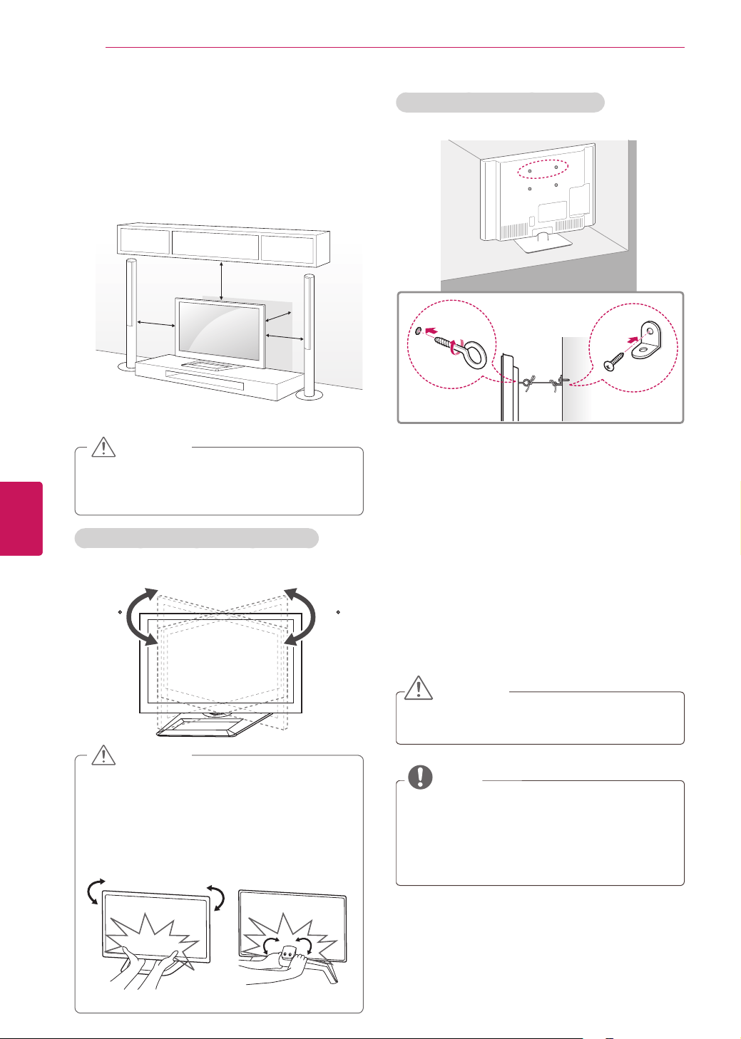
Adjusting the angle of the TV to suit view
Swivel 20±2 degrees to the left or right and adjust
the angle of the TV to suit your view.
2020
When adjusting the angle of the TV, watch
out for your fingers.
- Personal injury may occur if hands or
fingers are pinched. If the product is tilted
too much, it may fall, causing damage or
injury.
RearFront
CAUTION
Securing the TV to a wall (optional)
(Depending on model)
1
Insert and tighten the eye-bolts, or TV brackets
and bolts on the back of the TV.
- If there are bolts inserted at the eye-bolts
position, remove the bolts first.
2
Mount the wall brackets with the bolts to the
wall.
Match the location of the wall bracket and the
eye-bolts on the rear of the TV.
3
Connect the eye-bolts and wall brackets tightly
with a sturdy rope.
Make sure to keep the rope horizontal with the
flat surface.
CAUTION
Make sure that children do not climb on or
hang on the TV.
NOTE
Use a platform or cabinet that is strong and
large enough to support the TV securely.
Brackets, bolts and ropes are optional. You
can obtain additional accessories from your
local dealer.
21
ENG
ENGLISH
ASSEMBLING AND PREPARING
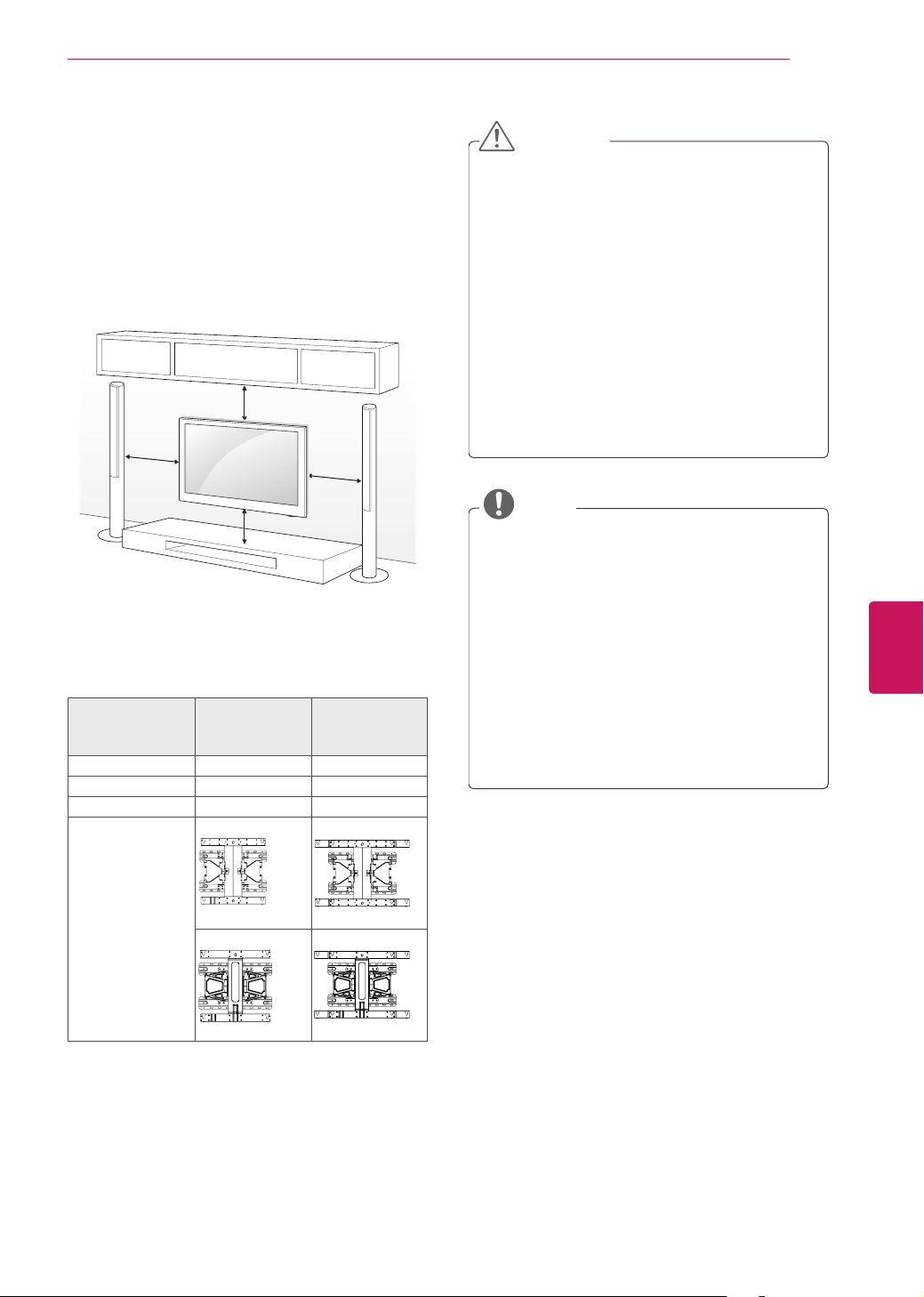
Mounting on a wall
Attach an optional wall mount bracket at the rear
of the TV carefully and install the wall mount
bracket on a solid wall perpendicular to the
floor. When you attach the TV to other building
materials, please contact qualified personnel.
We recommend that you use an LG brand wall
mount when mounting the TV to a wall.
10 cm
10 cm
10 cm
10 cm
(4 inches)
Make sure to use screws and wall mounts that
meet the VESA standard. Standard dimensions for
the wall mount kits are described in the following
table.
Model 42/50PM4700
50PM6700
50PM9700
60PM6700
60PM9700
VESA 400 x 400 600 x 400
Standard screw M6 M8
Number of screws 4 4
Wall mount
bracket (optional)
PSW400B
PSW600B
PSW420BX PSW620BX
CAUTION
Disconnect the power first, and then move
or install the TV. Otherwise electric shock
may occur.
If you install the TV on a ceiling or slanted
wall, it may fall and result in severe injury.
Use an authorized LG wall mount and contact
the local dealer or qualified personnel.
Do not over tighten the screws as this may
cause damage to the TV and void your
warranty.
Use the screws and wall mounts that meet
the VESA standard. Any damages or injuries
by misuse or using an improper accessory
are not covered by the warranty.
NOTE
Use the screws that are listed on the VESA
standard screw specifications.
The wall mount kit includes an installation
manual and necessary parts.
The wall mount bracket is optional. You can
obtain additional accessories from your local
dealer.
The length of screws may differ depending
on the wall mount. Make sure to use the
proper length.
For more information, refer to the manual
supplied with the wall mount.
22
ENG
ENGLISH
MAKING CONNECTIONS
MAKING CONNECTIONS
Connect various external devices to the TV and switch input modes to select an external device. For more
information on external device’s connection, refer to the manual provided with each device.
Available external devices are: HD receivers, DVD players, VCRs, audio systems, USB storage devices, PC,
gaming devices, and other external devices.
NOTE
If you record a TV program on a DVD recorder or VCR, make sure to connect the TV signal input cable
to the TV through a DVD recorder or VCR. For more information on recording, refer to the manual
provided with the connected device.
The external device connection may differ from the model.
Connect external devices to the TV regardless of the order of the TV port.
If you connect a gaming device to the TV, use the cable supplied with the gaming device.
Refer to the external equipment’s manual for operating instructions.
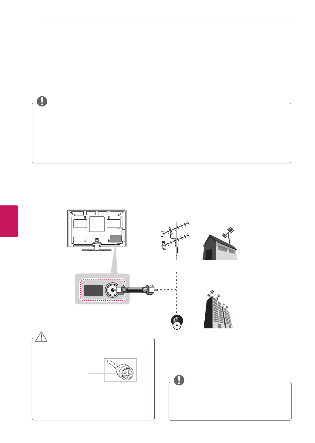
Connecting to an antenna or cable
Connect an antenna, cable, or cable box to watch TV while referring to the following. The illustrations may
differ from the actual items and a RF cable is optional.
CAUTION
Make sure not to bend the copper wire of
the RF cable.
Copper wire
Complete all connections between devices,
and then connect the power cord to the
power outlet to prevent damage to your TV.
NOTE
Use a signal splitter to use more than 2 TVs.
Visit http://lgknowledgebase.com for more
information about the antenna and cable
connection. Search for antenna.
ANTENNA/
CABLE IN
VHF Antenna
UHF Antenna
Antenna
Terminal
Coaxial (75Ω)
23
ENG
ENGLISH
MAKING CONNECTIONS
This part of MAKING CONNECTIONS mainly uses picture for PM6700 series.
Connecting to a HD receiver, DVD, or VCR player
Connect a HD receiver, DVD, or VCR player to the TV and select an appropriate input mode.
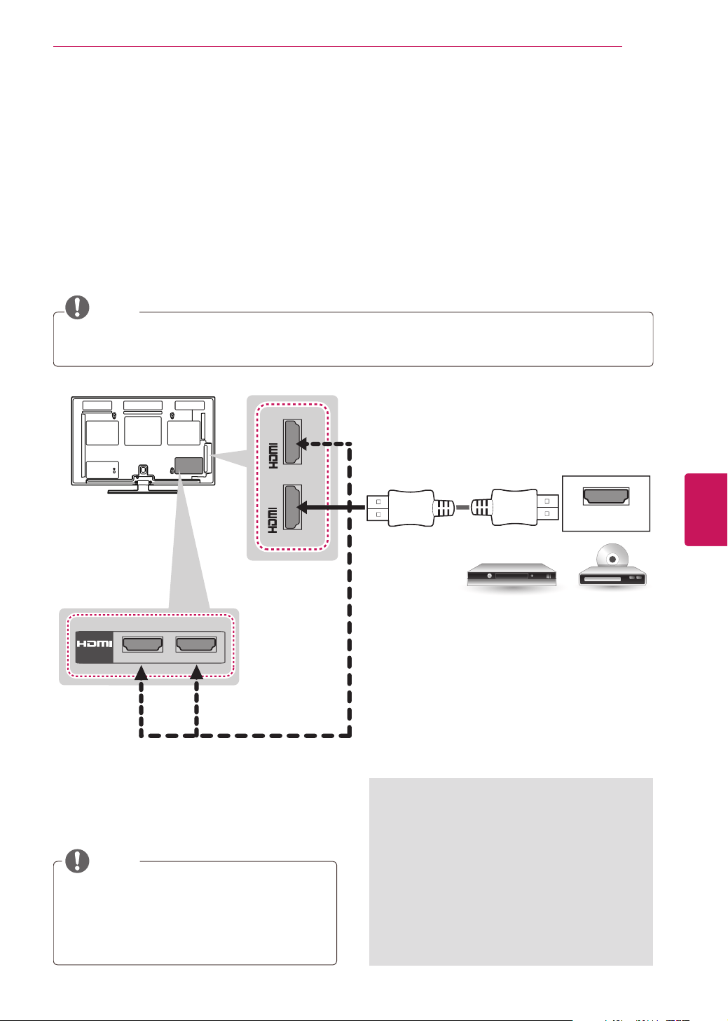
HDMI Connection
HDMI is the best way to connect a device.
Transmits the digital video and audio signals from an external device to the TV. Connect the external device
and the TV with the HDMI cable as shown in the following illustration.
NOTE
Use the latest High Speed HDMI™ Cable with CEC (Customer Electronics Control) function.
High Speed HDMI™ Cables are tested to carry an HD signal up to 1080p and higher.
HDMI
IN
3
4
IN 1(ARC)
/ DVI IN
2
(*Not Provided)
DVD/ Blu-Ray / HD Cable Box / HD STB
Choose any HDMI IN input port to connect.
It does not matter which port you use.
ARC (Audio Return Channel)
When connected with a high-speed
HDMI cable, digital audio can be sent
to a compactible device without an
additional optical audio cable.
ARC is only supported on the HDMI
input 1 (ARC) port. An external audio
device that supports ARC should be
connected to HDMI 1 if you wish to
use ARC.
NOTE
DTV Audio Supported Codec: MPEG, Dolby
Digital
HDMI Audio Supporeted Format: Dolby
Digital, PCM (Up to 192 KHz, 32k/44.1k/48k/
88k/96k/176k/192k) -> Not supported DTS.
(For PM6700,
PM9700 series)
24
ENG
ENGLISH
MAKING CONNECTIONS
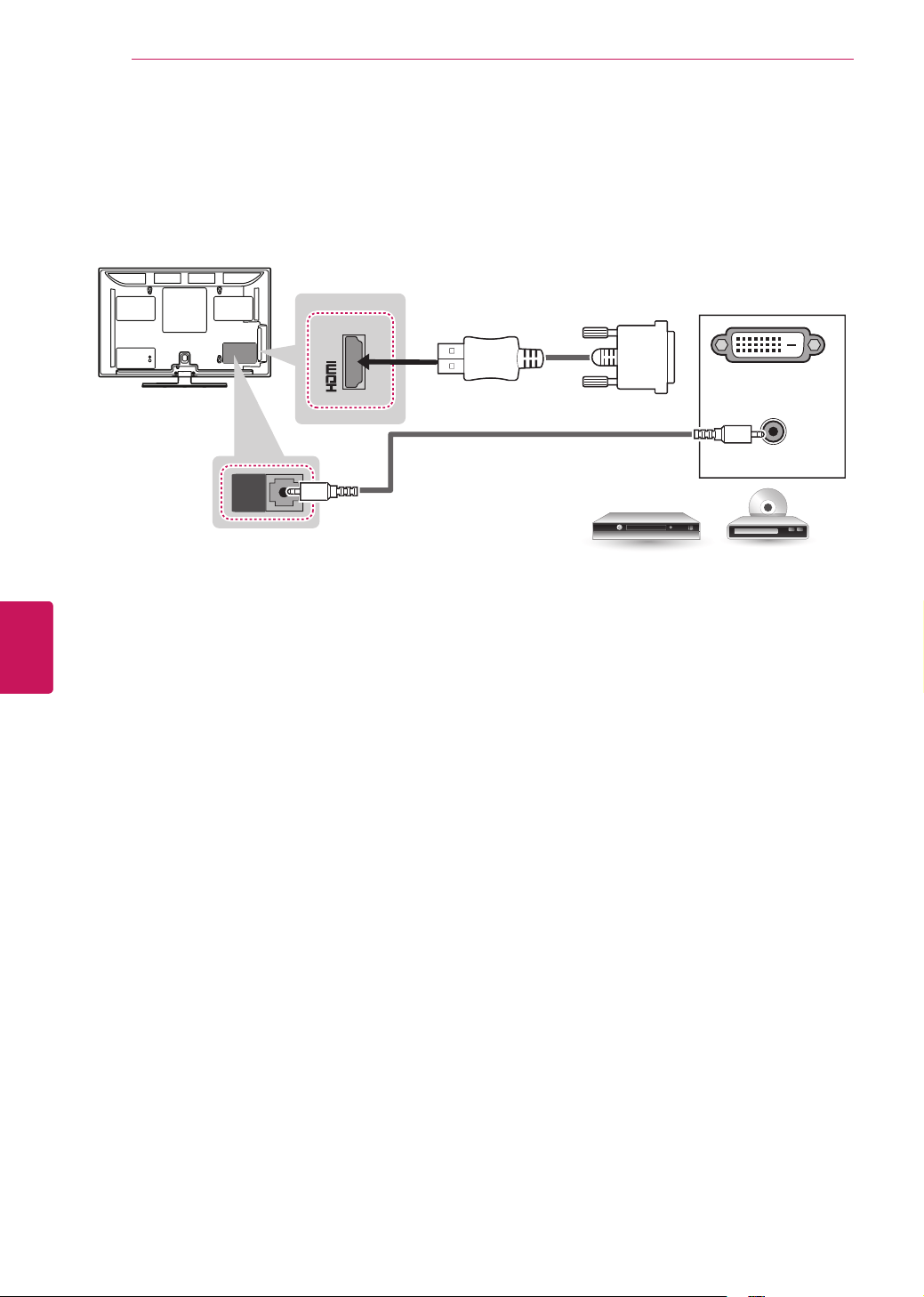
DVI to HDMI Connection
Transmits the digital video signal from an external device to the TV. Connect the external device and the
TV with the DVI-HDMI cable as shown in the following illustration. To transmit an audio signal, connect an
audio cable.
AUDIO OUT
DVI OUT
AUDIO IN
/DVI IN
2
AUDIO IN
(RGB/DVI)
(*Not Provided)
(*Not Provided)
DVD/ Blu-Ray / HD Cable Box
25
ENG
ENGLISH
MAKING CONNECTIONS
DVD/ Blu-Ray / HD Cable Box
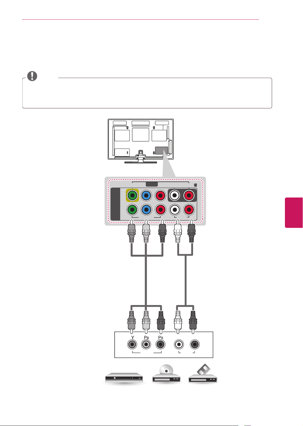
Component Connection
Transmits analog video and audio signals from an external device to the TV. Connect the external device
and the TV with a component cable as shown in the following illustration.
NOTE
If cables are installed incorrectly, it could case the image to display in black and white or with
distorted color.
Check to ensure each cable is matched with the corresponding color connection.
AUDIO
VIDEO
L R
COMPONENT IN
VIDEO
AUDIO
LP
B
P
R
R
1
2
Y
VIDEO
AUDIO
R
L/MONO
AV IN
(*Not Provided)
(*Not Provided)
DVD/ Blu-Ray / HD Cable Box
GREEN
GREEN
BLUE
BLUE
RED
RED
WHITE
WHITE
RED
RED
26
ENG
ENGLISH
MAKING CONNECTIONS
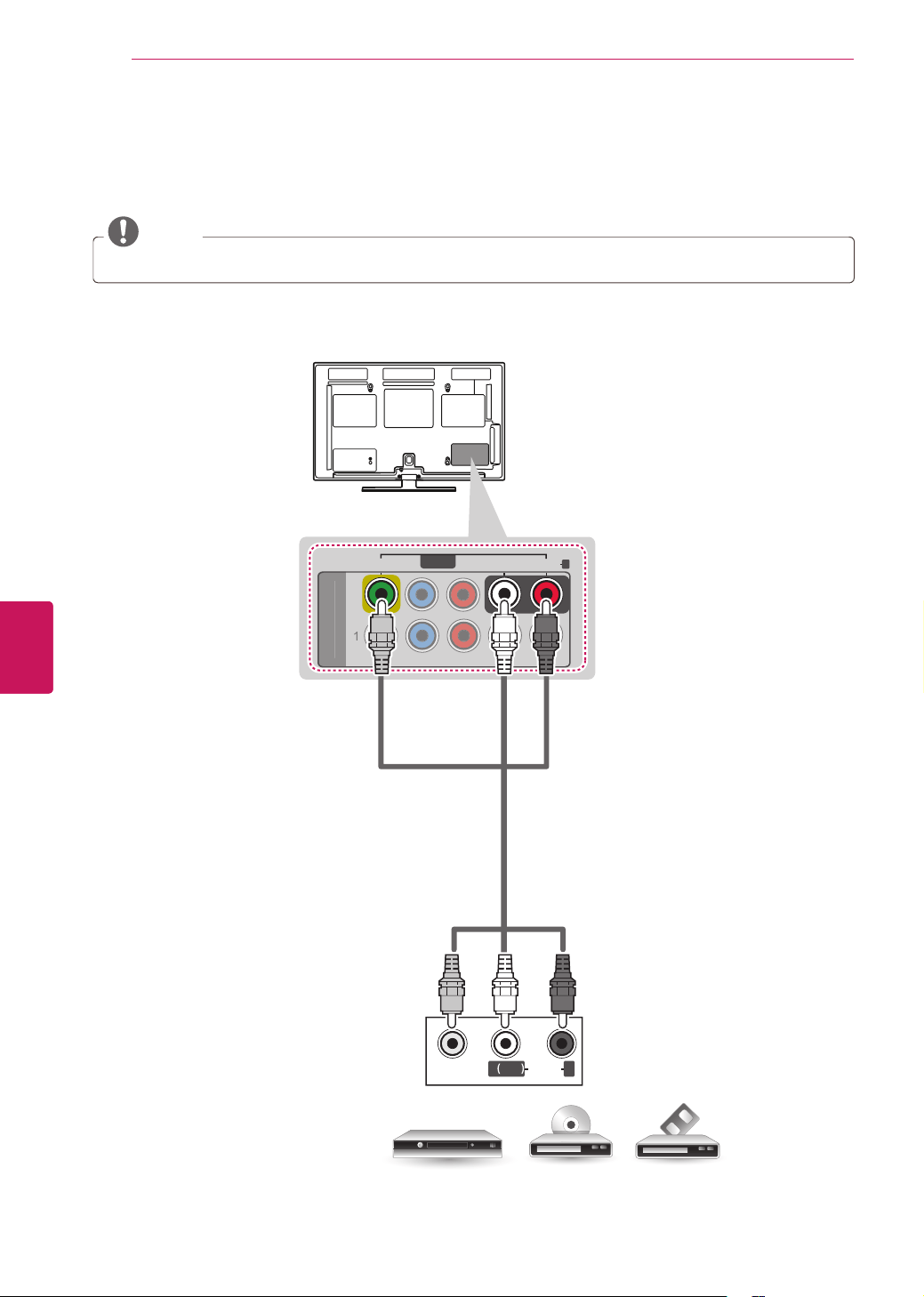
Composite Connection
Transmits analog video and audio signals from an external device to the TV. Connect the external device
and the TV with the composite cable as shown in the following illustration.
NOTE
If you have a mono VCR, connect the audio cable from the VCR to the AUDIO L/MONO jack of the TV.
VIDEO
MONO
( )
AUDIOL R
C
O
MP
O
NENT I
N
L
P
B
P
R
R
1
2
Y
VIDEO
AUDIO
R
L/MONO
AV IN
VCR / DVD/ Blu-Ray / HD Cable Box
YELLOW
WHITE
RED
YELLOW
WHITE
RED
(*Not Provided)
27
ENG
ENGLISH
MAKING CONNECTIONS
Connecting to a PC
NOTE
It is recommended to use the HDMI connection for the best image quality.
Depending on the graphics card, DOS mode video may not work if a HDMI to DVI Cable is in use.
In PC mode, there may be noise associated with the resolution, vertical pattern, contrast or
brightness. If noise is present, change the PC output to another resolution, change the refresh rate to
another rate or adjust the brightness and contrast on the PICTURE menu until the picture is clear.
The synchronization input form for Horizontal and Vertical frequencies is separate.
Depending on the graphics card, some resolution settings may not allow the image to be positioned
on the screen properly.
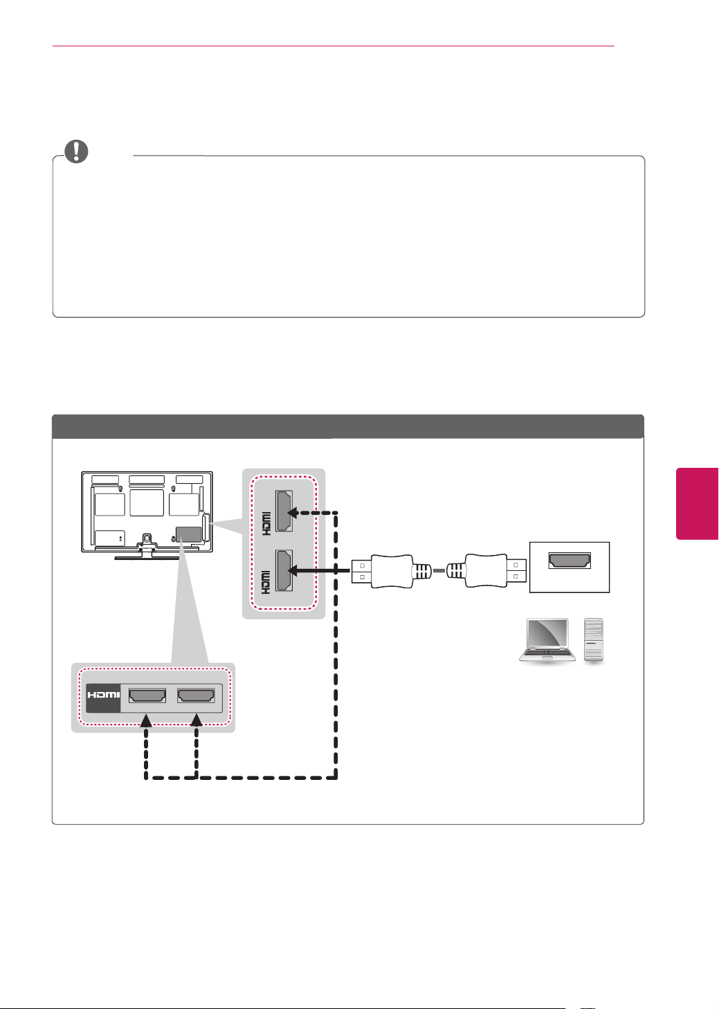
HDMI Connection, DVI to HDMI Connection or RGB Connection
Choose method A, B, or C to make connection.
Method A: HDMI Connection
5*%2873&
$8',2287
$8',2287
'9,287
㶌⸬ (ARC)
/DVI IN
2
AUDIO IN
(RGB/DVI)
HDMI
IN
3
4
IN 1(ARC)
/ DVI IN
2
AUDIO IN
(RGB/DVI)
RGB IN
(PC)
Choose any HDMI input port to connect.
It does not matter which port you use.
PC
(*Not Provided)
(For PM6700,
PM9700 series)

28
ENG
ENGLISH
MAKING CONNECTIONS
Method C: RGB Connection
Method B: DVI to HDMI Connection
PC
(*Not Provided)
(*Not Provided)
(*Not Provided)
(*Not Provided)
PC
5*%2873&
$8',2287
$8',2287
'9,287
㶌⸬ (ARC)
/DVI IN
2
AUDIO IN
(RGB/DVI)
HDMI
IN
3
4
IN 1(ARC)
/ DVI IN
2
AUDIO IN
(RGB/DVI)
RGB IN
(PC)
5*%2873&
$8',2287
$8',2287
'9,287
㶌⸬ (ARC)
/DVI IN
2
AUDIO IN
(RGB/DVI)
HDMI
IN
3
4
IN 1(ARC)
/ DVI IN
2
AUDIO IN
(RGB/DVI)
RGB IN
(PC)
29
ENG
ENGLISH
MAKING CONNECTIONS
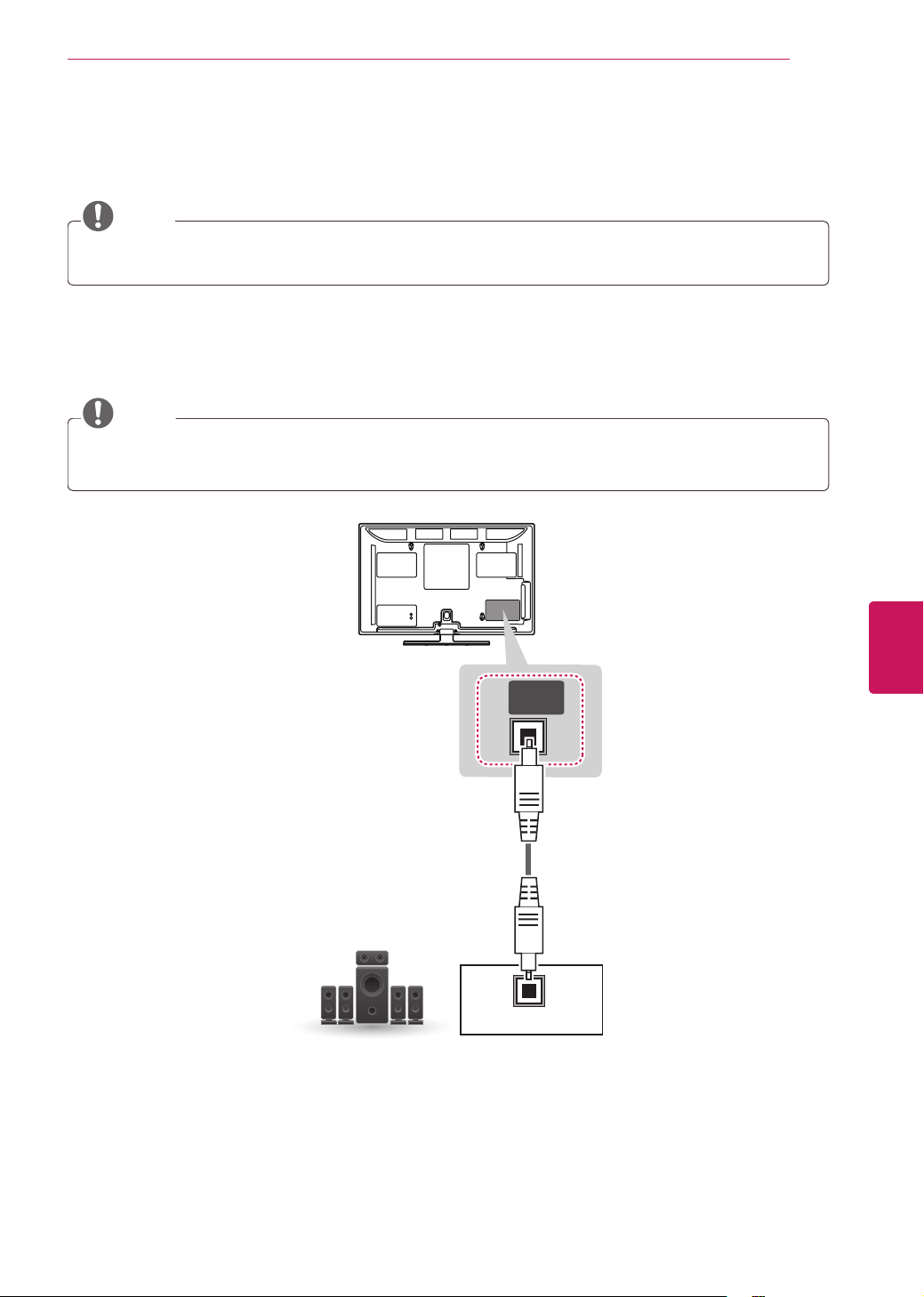
Connecting to an Audio System
You may use an optional external audio system instead of the built-in speaker.
NOTE
If you use an optional external audio device instead of the built-in speaker, set the TV speaker feature
to off.
Digital Optical Audio Connection
Transmits a digital audio signal from the TV to an external device. Connect the external device and the TV
with the optical audio cable as shown in the following illustration.
NOTE
Do not look into the optical output port. Looking at the laser beam may damage your vision.
Audio with ACP (Audio Copy Protection) function may block digital audio output.
OPTICAL
AUDIO IN
OPTICAL
DIGITAL
AUDIO OUT
(*Not Provided)
Digital Audio System
30
ENG
ENGLISH
MAKING CONNECTIONS
USB IN 1 / USB Apps
USB IN 2
USB Hub
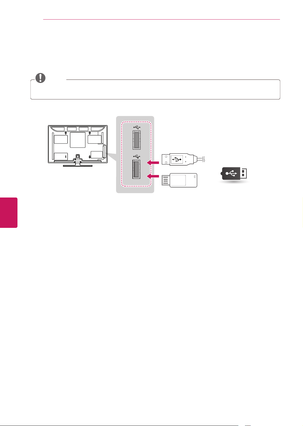
Connecting to a USB
Connect a USB storage device such as a USB flash memory, external hard drive, or a USB memory card
reader to the TV and access the Smart Share menu to use various multimedia files.
NOTE
To store apps on a USB storage device, make sure that it is connected to the USB IN 1 port.
To use a USB Hub device, make sure that it is connected to the USB IN 1 port.
USB
(*Not Provided)
Choose any USB input port to connect.
It does not matter which port you use.
31
ENG
ENGLISH
REMOTE CONTROL
CHVOL
1 2 3
4 5 6
7 8
0
9
P
A
G
E
TV
RATIO
INPUT
FAV
MUTE
LIST
FLASHBK
EXIT
OK
Q.MENU
SETTINGS
AV MODE
ENERGY
SAVING
MY APPS
HOME
INFO
Make sure to point the remote control toward at the remote control sensor on the TV.
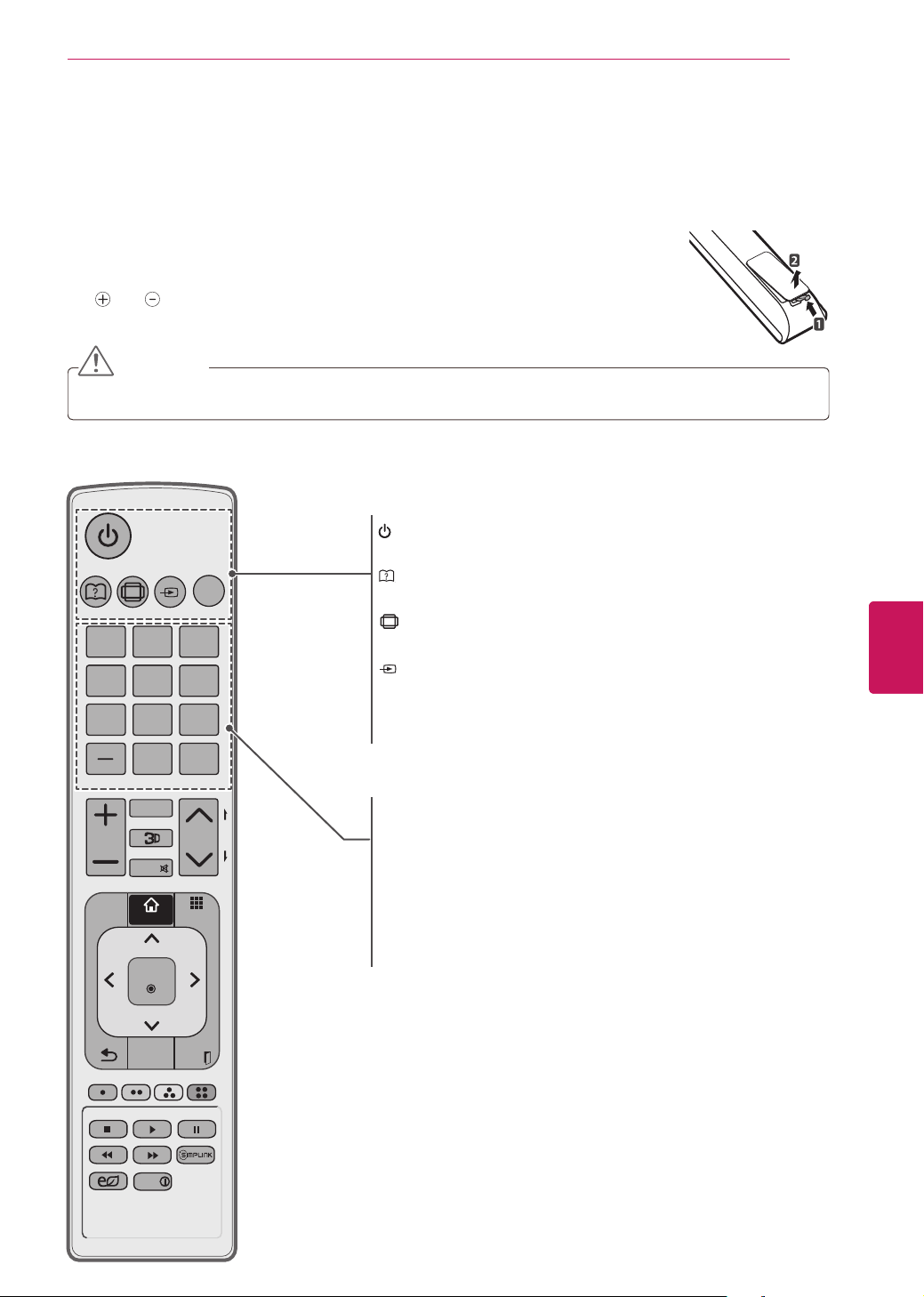
REMOTE CONTROL
For PM4700, PM6700-UB series
The descriptions in this manual are based on the buttons on the remote control.
Please read this manual carefully and use the TV correctly.
To replace batteries, open the battery cover, replace batteries (1.5 V AAA) matching
the
and ends to the label inside the compartment, and close the battery cover. To
remove the batteries, perform the installation actions in reverse.
CAUTION
Do not mix old and new batteries, as this may damage the remote control.
(POWER
)
Turns the TV on or off.
HOMEBACK
VOL CH
My APPS
(User-Guide)
Sees User-Guide.
REC
RATIO
Resizes an image.
REC
INPUT
Changes the input source; Turns the TV on.
TV
Returns to the last TV channel.
Number button
Enters numbers.
LIST, - (Dash)
LIST: Accesses the saved channel list.
- (Dash): Inserts a dash between numbers such as 2-1 and 2-2.
FLASHBK
Alternates between the two last channels selected (pressing
repeatedly).
32
ENG
ENGLISH
REMOTE CONTROL
CHVOL
1 2 3
4 5 6
7 8
0
9
P
A
G
E
TV
RATIO
INPUT
FAV
MUTE
LIST
FLASHBK
EXIT
OK
Q.MENU
SETTINGS
AV MODE
ENERGY
SAVING
MY APPS
HOME
INFO
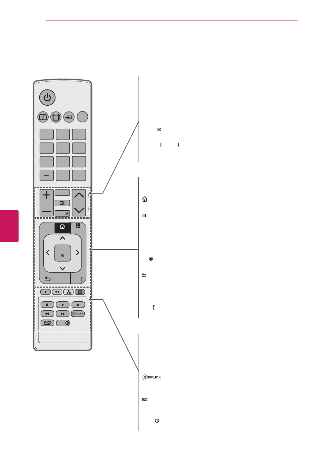
+ VOL -
Adjusts the volume level.
FAV
Accesses your favorite channel list.
3D
Used for viewing 3D video.
MUTE
REC
Mutes all sounds.
^
CH
v,
REC
PAGE
REC
CH: Scrolls through the saved channels.
PAGE: Moves to the previous or next screen.
SETTINGS
Accesses the main menu.
REC
HOME
Accesses the HOME menu.
REC
MY APPS
Shows the list of Apps.
Q. MENU
Accesses the quick menu.
Navigation buttons
(up/down/left/right)
Scrolls through menus or options.
OK
REC
Selects menus or options and confirms your input.
REC
(BACK)
Returns to the previous level.
AV MODE
Selects an AV mode.
EXIT
REC
Clears all on-screen displays and returns to TV viewing.
Color buttons
These access special functions in some menus.
Control buttons
Controls the Premium contents, Smart Share menus, or the
SIMPLINK compatible devices (USB,SIMPLINK).
REC
Accesses the AV devices connected to the TV;
Opens the SIMPLINK menu.
REC
ENERGY SAVING
Adjusts the brightness of the screen to reduce energy
consumption.
INFO
REC
Views the information of the current program and screen.
33
ENG
ENGLISH
REMOTE CONTROL
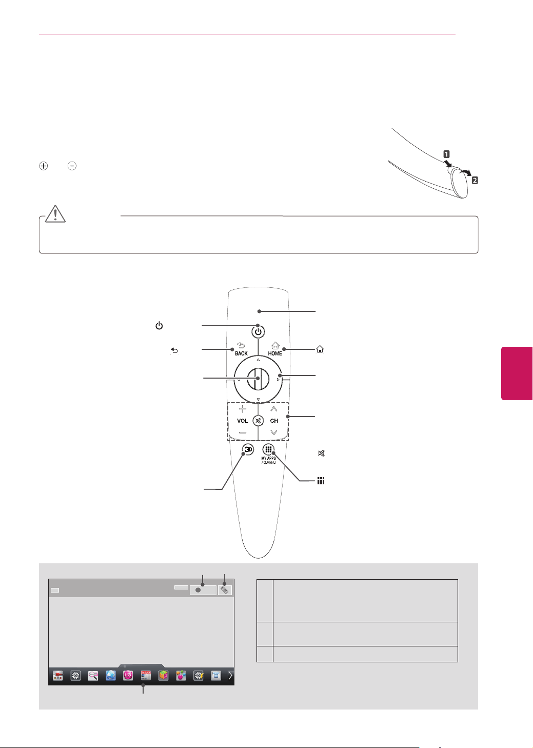
Magic Remote Control Functions
For PM9700, PM6700-UD series
When the message “Magic remote control battery is low. Change the battery.” is
displayed, replace the battery.
To replace batteries, open the battery cover, replace batteries (1.5 V AA) matching
and ends to the label inside the compartment, and close the battery cover. Be
sure to point the remote control at the remote control sensor on the TV.
To remove the batteries, perform the installation actions in reverse.
CAUTION
Do not mix old and new batteries, as this may damage the remote control.
Do not need RF dongle which is built in.
Make sure to point the remote control at the remote control sensor on the TV.
(POWER
)
Turns the TV on or off.
Pointer (RF & Bluetooth transmitter)
Blinks the light when operating.
HOMEBACK
VOL CH
My APPS
HOME
Accesses the Home menu.
Navigation buttons
(up/down/left/right)
Scrolls through menus or options.
HOMEBACK
VOL CH
My APPS
BACK
Returns to the previous level.
+ VOL -
Adjusts the volume level.
^
CH
v
Scrolls through the saved channels.
HOMEBACK
VOL CH
My APPS
(MUTE)
Mutes all sounds.
HOMEBACK
VOL CH
My APPS
MY APPS
Shows the list of Apps.
Q. MENU
Accesses the quick menu.
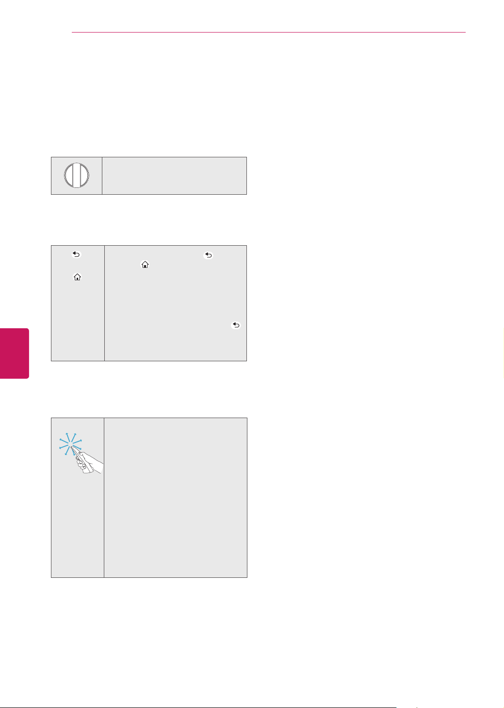
Wheel (OK)
Selects menus or options and confirms
your input;
Scrolls through the saved channels.
If you press the navigation button while
moving the pointer on the screen,
the pointer disappears, and the Magic
remote control works as a regular
remote control.
To display the pointer again, shake the
Magic remote control from side to side.
3D
Uses for viewing 3D video.
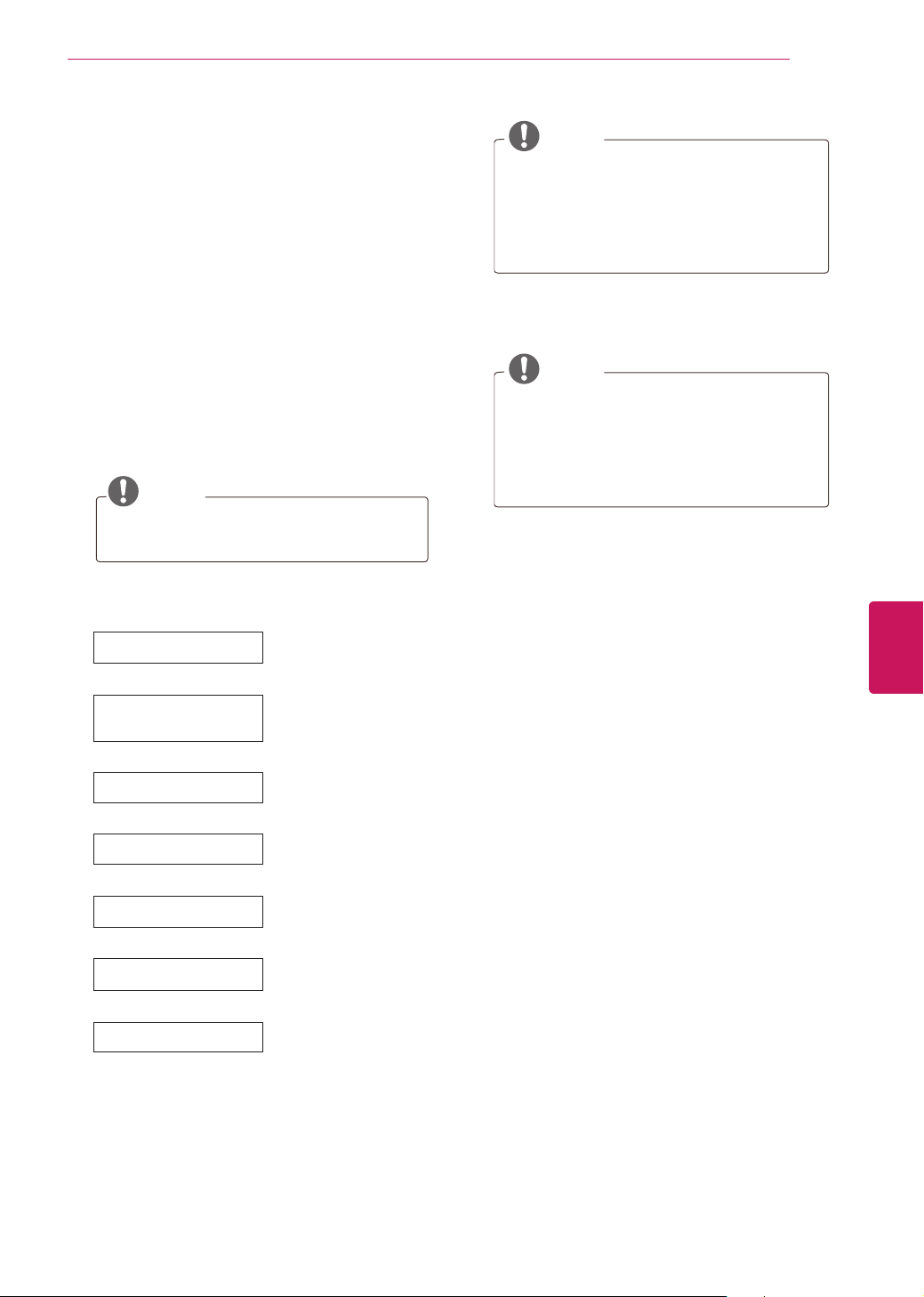
1
If you press the
Wheel (OK)
button on the Magic
remote control, the following screen appears.
Shows information about the current program
and screen.
2
Pressing this button will display number
keypad which you can select channel number.
3
You can select My apps Menu.
11
-1
Brief Info Title Test...
Info.
ꘄ
11:40 AM
TV
i
1
3
2
34
ENG
ENGLISH
REMOTE CONTROL
Registering Magic Remote Control
The Magic remote Control operates by pairing with
your TV. Once you purchased the TV, please
register the Magic remote control as follows;
How to register the Magic Remote Control
HOMEBACK
VOL CH
My APPS
To register the remote control, press
the
Wheel (OK)
button on the remote
control.
How to Re-register the Magic Remote Control
after Registration Failure
BACK
HOMEBACK
VOL CH
My APPS
HOMEBACK
VOL CH
My APPS
HOME
1 Press and hold the
BACK
HOMEBACK
VOL CH
My APPS
and
HOME
HOMEBACK
VOL CH
My APPS
buttons together for 5
seconds to reset, then register it
by following “How to register the
Magic remote control” above. (Once
the reset is complete, the light on
the Pointer blinks.)
2 To re-register the Magic remote
control, press and hold the
BACK
HOMEBACK
VOL CH
My APPS
button for 5 seconds toward the TV.
(Once the reset is complete, the
light on the Pointer blinks.)
How to use Magic Remote
Control
1 If the pointer disappears, move
the remote control slightly to left
or right. Then, it will automatically
appear on the screen.
»
If the pointer has not been used
for a certain period of time, it
will disappear.
2 You can move the pointer by
aiming the Pointer Receiver of
the remote control at your TV
then move it left, right, up or
down.
»
If the pointer does not work
properly after clicking the
Wheel (OK)
button, leave
the remote control for 10
seconds then use it again.
Precautions to Take when Using
the Magic Remote Control
Use the remote control within the maximum
communication distance (10 m, 32.8ft).
Using the remote control beyond this
distance, or with an object obstructing it,
may cause a communication failure.
A communication failure may occur due to
nearby devices. Electrical devices such as
a microwave oven or wireless LAN product
may cause interference, as these use the
same bandwidth (2.4 GHz) as the Magic
Remote Control.
The Magic Remote Control may be damaged
or may malfunction if it is dropped or
receives a heavy impact.
Take care not to bump into nearby furniture
or other people when using the Magic
Remote Control.
Manufacturer and installer cannot provide
service related to human safety as the
applicable wireless device has possibility of
electric wave interference.
It is recommended that an Access Point (AP)
be located more than 1 m (3.28 ft) away
from the TV. If the AP is installed closer than
1 m (3.28 ft), the magic remote control may
not perform as expected due to frequency
interference.
35
ENG
ENGLISH
WATCHING TV
NOTE
Select
Home*
when prompted.
Store*
mode puts the TV in demo mode.
If you select
Store*
, the any customized
settings will switch back to the default
settings of
Store*
in 5 minutes.
4
When the basic settings are complete,
press the
Wheel (OK)
button.
NOTE
If you do not complete the Initial setting,
it will appear whenever the TV turns on.
Disconnect the power cord from the
power outlet when you do not use the
TV for a long period of time.
5
To turn the TV off, press the power button on
the remote control.
WATCHING TV
Turning the TV on for the first
time
When you turn the TV on for the first time, the
Initial setting screen appears. Select a language
and customize the basic settings.
1
Connect the power cord to a power outlet.
2
In Standby mode, press the power button on
the remote control to turn the TV on.
The Initial setting screen appears if you turn
the TV on for the first time.
NOTE
You can also access
Initial Setting
by
accessing
OPTION
in the main menu.
3
Follow the on-screen instructions to customize
your TV settings according to your preferences.
Language Selection*
Selects a language to
display.
Using the Magic remote
control
Sets the Magic remote
contol.
Enviroment Selection
Select
Home*
for the
home environment.
Time Zone Setting
Selects the time zone
and daylight saving.
(Depending on country.)
Network Connection
Sets your network to
enable network-related
features on the TV.
Auto Tuning
Scans and saves available
channels automatically.
Setting is completed.
Confirms the setting
options.
36
ENG
ENGLISH
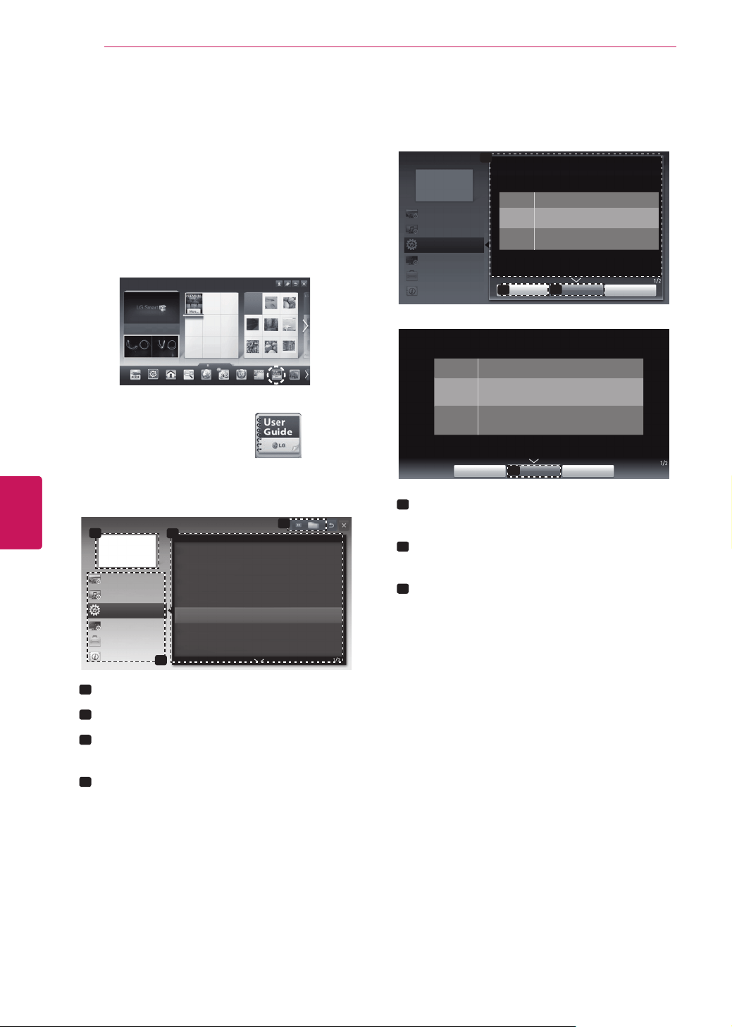
USING THE USER GUIDE
User Guide allows you to more easily access the
detailed TV information.
1
Press the
HOME
button to access the HOME
menu.
2
Select User Guide and press the
Wheel (OK)
button.
Input List Settings Live TV
Search
Internet
3D
LG Smart W
TV Guide User Guide
Ch. List
User Guide
1
3
4
2
User Guide
OPTION
CHANNEL Setting
PICTURE,SOUND setting
Advanced Function
LG Smart Function
To use input device
To set time options
To set language
To set Magic remote control
To set TV lock options
To use Energy Saving feature
Information
To set other options
1
Shows the current channel.
2
Allows to select the category you want.
3
Allows to select the item you want.
You can use
ꕌ
/
ꕍ
to move between pages.
4
Allows to browse the description of the
function you want from the index.
1
2
3
User Guide
OPTION
CHANNEL Setting
PICTURE, SOUND Setting
Advabced Function
LG SMART Function
Information
Try Now
Close
Zoom In
OPTION > To set language
HOME Settings OPTION Language
Selects Menu Language and Audio Language displayed on the screen.
Menu
Language
Selects a screen menu language.
Audio
Language
[In Digital Mode Only]
Selects the desired language when watching digital
broadcasting containing several audio languages.
Voice Search
Language
Select the language to make voice search.
✎
Only the voice search adopted model can support this
setting.
3
Try Now
Close
Zoom Out
HOME Settings OPTION Language
Selects Menu Language and Audio Language displayed on the screen.
Menu
Language
Selects a screen menu language.
Audio
Language
[In Digital Mode Only]
Selects the desired language when watching digital
broadcasting containing several audio languages.
Voice Search
Language
Select the language to make voice search.
✎
Only the voice search adopted model can support this
setting.
1
Shows the description of the selected menu.
You can use
ꕌ
/
ꕍ
to move between pages.
2
Moves to the selected menu directly from
the User Guide.
3
Zooms in or out the screen.
USING THE USER GUIDE
37
ENG
ENGLISH
TROUBLESHOOTING / EXTERNAL CONTROL DEVICE SETUP
TROUBLESHOOTING
General
Problem Solution
Cannot control the TV with the
remote control.
Check the remote control sensor on the product and try again.
Check if there is any obstacle between the product and the remote control.
Check if the batteries are still working and properly installed (
to , to ).
No image display and no sound is
produced.
Check if the product is turned on.
Check if the power cord is connected to a wall outlet.
Check if there is a problem in the wall outlet by connecting other products.
The TV turns off suddenly.
Check the power control settings. The power supply may be interrupted.
Check if the Auto sleep feature is activated in the Time settings.
If there is no signal while the TV is on, the TV will turn off automatically after
15 minutes of inactivity.
When connecting to the PC (RGB/
HDMI DVI) ‘No Signal’ or ‘Invalid
Format’ is displayed.
Turn the TV off/on.
Reconnect the RGB/HDMI cable.
Restart the PC with the TV on.
EXTERNAL CONTROL DEVICE SETUP
To obtain the external control device setup information, please visit www.lg.com.
38
ENG
ENGLISH
SPECIFICATIONS
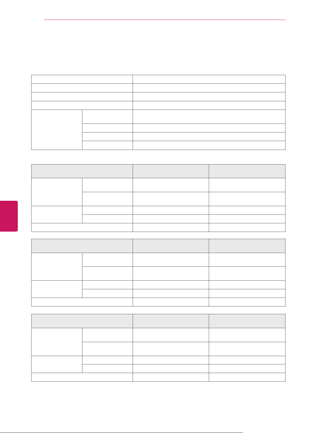
SPECIFICATIONS
Power requirement AC 100 - 240 V ~ 50 / 60 Hz
Television System NTSC-M, ATSC, 64 & 256 QAM
Program Coverage VHF 2-13, UHF 14-69, CATV 1-135, DTV 2-69, CADTV 1-135
External Antenna Impedance
75
Ω
Environment
condition
Operating
Temperature
0 - 40 °C
Operating Humidity Less than 80 %
Storage Temperature -20 - 60 °C
Storage Humidity Less than 85 %
Product specifications may be changed without prior notice due to upgrade of product functions.
MODELS
42PM4700
(42PM4700-UB)
50PM4700
(50PM4700-UB)
Dimensions
(Width x Height x
Depth)
With stand
983.6 mm x 655.0 mm x 246.7 mm
(38.7 inch x 25.7 inch x 9.7 inch)
1168.0 mm x 758.0 mm x 297.0 mm
(45.9 inch x 29.8 inch x 11.6 inch)
Without stand
983.6 mm x 601.3 mm x 58.0 mm
(38.7 inch x 23.6 inch x 2.2 inch)
1168.0 mm x 704.0 mm x 53.0 mm
(45.9 inch x 27.7 inch x 2.0 inch)
Weight With stand 20.6 kg (45.4 lbs) 28.2 kg (62.1 lbs)
Without stand 19.0 kg (41.8 lbs) 25.8 kg (56.8 lbs)
Current Value / Power consumption 2.3 A / 230 W 3.0 A / 300 W
MODELS
50PM6700
(50PM6700-UB)
60PM6700
(60PM6700-UB)
Dimensions
(Width x Height x
Depth)
With stand
1168.0 mm x 758.0 mm x 297.0 mm
(45.9 inch x 29.8 inch x 11.6 inch)
1386.8 mm x 883.2 mm x 354.7 mm
(54.5 inch x 34.7 inch x 13.9 inch)
Without stand
1168.0 mm x 704.0 mm x 53.0 mm
(45.9 inch x 27.7 inch x 2.0 inch)
1386.8 mm x 818.2 mm x 53.0 mm
(54.5 inch x 32.2 inch x 2.0 inch)
Weight With stand 28.8 kg (64.3 lbs) 40.6 kg (89.5 lbs)
Without stand 26.4 kg (58.2 lbs) 36.4 kg (80.2 lbs)
Current Value / Power consumption 3.2 A / 320 W 4.6 A / 460 W
MODELS
50PM6700
(50PM6700-UD)
60PM6700
(60PM6700-UD)
Dimensions
(Width x Height x
Depth)
With stand
1168.0 mm x 768.0 mm x 297.0 mm
(45.9 inch x 30.2 inch x 11.6 inch)
1386.8 mm x 906.0 mm x 346.0 mm
(54.5 inch x 35.6 inch x 13.6 inch)
Without stand
1168.0 mm x 704.0 mm x 53.0 mm
(45.9 inch x 27.7 inch x 2.0 inch)
1386.8 mm x 818.2 mm x 53.0 mm
(54.5 inch x 32.2 inch x 2.0 inch)
Weight With stand 28.1 kg (61.9 lbs) 39.8 kg (87.7 lbs)
Without stand 26.4 kg (58.2 lbs) 36.4 kg (80.2 lbs)
Current Value / Power consumption 3.2 A / 320 W 4.6 A / 460 W

39
ENG
ENGLISH
SPECIFICATIONS
MODELS
50PM9700
(50PM9700-UA)
60PM9700
(60PM9700-UA)
Dimensions
(Width x Height x
Depth)
With stand
1168.0 mm x 765.0 mm x 297.0 mm
(45.9 inch x 30.1 inch x 11.6 inch)
1386.8 mm x 897.0 mm x 346.0 mm
(54.5 inch x 35.3 inch x 13.6 inch)
Without stand
1168.0 mm x 701.0 mm x 53.4 mm
(45.9 inch x 27.5 inch x 2.1 inch)
1386.8 mm x 827.2 mm x 53.4 mm
(54.5 inch x 32.5 inch x 2.1 inch)
Weight With stand 28.2 kg (62.1 lbs) 40.2 kg (88.6 lbs)
Without stand 26.5 kg (58.4 lbs) 36.8 kg (81.1 lbs)
Current Value / Power consumption 3.2 A / 320 W 4.6 A / 460 W
40
ENG
ENGLISH
SPECIFICATIONS
3D supported mode
Media contents and a player need to support HDMI 3D Frame Packing, HDMI 3D Side by Side, HDMI 3D
Top & Bottom to play in 3D.
Video, which is input as HDMI,USB,DLNA, is switched into the 3D screen automatically. (This funtion does
not support all of the 3D video format. The specific 3D video format is not switched into the 3D screen
automatically.)
2D -> 3D mode is available to watch for all signals.
For models supporting WiDi, you can set the 3D mode in the same way as in RGB (PC) mode.
Input Signal Resolution
Horizontal
Frequency (kHz)
Vertical
Frequency (Hz)
Playable 3D video format
HDMI-DTV
480p
640X480
62.938 / 63
59.94/ 60
Frame packing, Line alternative
720X480
640X480
31.469 / 31.5
Side-by-side(Full), Top-and-Bottom,
Side-by-side(half)
720X480
720p 1280X720
89.91/90 59.94 / 60
Frame packing, Line alternative
44.96 / 45 59.94 / 60
Side-by-side(Full), Top-and-Bottom
Side-by-side(half), Single Frame Sequential
1080i
1920X1080
67.432 / 67.5 59.94 / 60
Frame packing, Field alternative
33.72 / 33.75 59.94 / 60
Side-by-side(Full), Top-and-Bottom,
Side-by-side(half)
1080p
1920X1080
53.946 / 54 23.97 / 24
Frame packing, Line alternative
67.432/67.5 29.976 / 30
26.97 / 27 23.97 / 24
Side-by-side(Full), Top-and-Bottom,
Side-by-side(half), Checkerboard
33.716 / 33.75 29.976 / 30.00
67.43 / 67.5 59.94 / 60
Top-and-Bottom, Side-by-side(half),
Checkerboard, Single Frame Sequential,
Row Interleaving, Column Interleaving
HDMI-PC
1024x768 48.363 60.004
Side by Side(Half), Top & Bottom
1360x768 47.712 60.015
Side by Side(Half), Top & Bottom
1920x1080 67.50 60.00
Side by Side(Half), Top & Bottom
Checkerboard, Single Frame Sequential
Row Interleaving, Column Interleaving
RGB-PC
1024x768 48.363 60.004
Side by Side(Half), Top & Bottom
1360x768
47.712 60.015
Side by Side(Half), Top & Bottom
1920x1080 67.50 60.00
Side by Side(Half), Top & Bottom
Component
720p 1280X720 44.96 / 45 59.94 / 60
Side by Side, Top & Bottom
1080i 1920X1080 33.72 / 33.75 59.94 / 60
USB 1080p 1920X1080 33.75 30
Side by Side, Top & Bottom,
Checker Board, Single Frame Sequential,
Row Interleaving, Column Interleaving,
MPO(Photo), JPS(Photo)
(Photo : Side by Side(half), Top & Bottom)
DLNA 1080p 1920X1080 33.75 30
Side by Side, Top & Bottom,
Checker Board, Single Frame Sequential,
Row Interleaving, Column Interleaving,
MPO(Photo), JPS(Photo)
(Photo : Side by Side(half), Top & Bottom)
Signal Playable 3D video format
DTV 720p, 1080i
Side by Side, Top & Bottom
41
ENG
ENGLISH
SPECIFICATIONS
HDMI/DVI-DTV supported mode
Resolution
Horizontal
Frequency (kHz)
Vertical
Frequency (Hz)
720x480
31.469
31.5
59.94
60
1280x720
44.96
45
59.94
60
1920x1080
33.72
33.75
26.97
27
33.716
33.75
67.43
67.5
59.94
60
23.97
24
29.976
30.00
59.94
60
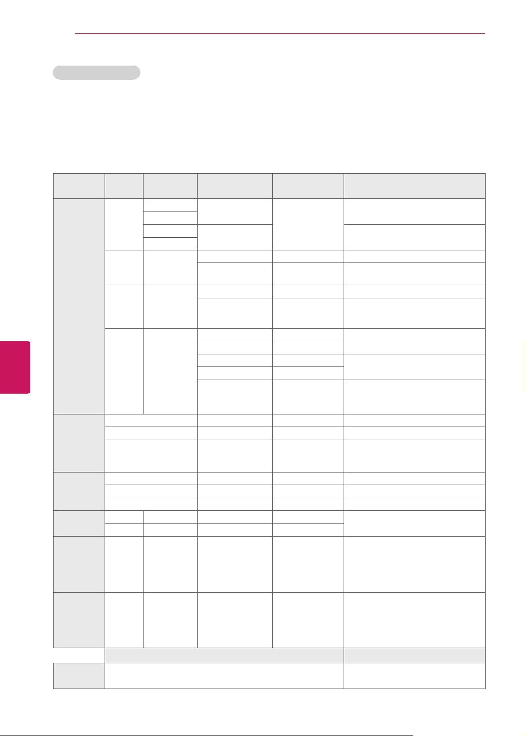
Component port connecting information
Component ports
on the TV
Y P
B
P
R
Video output ports
on DVD player
Y P
B
P
R
Y B-Y R-Y
Y Cb Cr
Y Pb Pr
Signal Component
480i O
480p O
720p/1080i O
1080p
O
(60 Hz only)
Wireless LAN module(TWFM-B003D) specification
Standard
IEEE802.11a/b/g/n
Frequency Range
2400 to 2483.5 MHz
5150 to 5250 MHz
5725 to 5850 MHz
Modulation
CCK / OFDM / MIMO
Output Power
(Typical)
802.11a: 15 dBm
802.11b: 14 dBm
802.11g: 17 dBm
802.11n - 2.4GHz: 17 dBm
802.11n - 5GHz: 15 dBm
Data rate
802.11a/g: 54 Mbps
802.11b: 11 Mbps
802.11n: 300 Mbps
Antenna Gain
(Typical)
2400 to 2483.5 MHz: -2.5 dBi
5150 to 5250 MHz: -2.2 dBi
5725 to 5850 MHz: -2.9 dBi
Occupied bandwidth
802.11a/b/g: HT20
802.11n: HT20/40
Because band channel used by the country could
be different, the user can not change or adjust the
operating frequency and this product is set for the
regional frequency table.
FCC ID of Wi-Fi module inside TV
FCC ID: BEJTWFM-B003D
Bluetooth module (BM-LDS302) specification
Standard
Bluetooth Version 3.0
Frequency Range
2400 ~ 2483.5 MHz
Output Power (Max.)
10 dBm or lower
Data rate (Max.)
3 Mbps
C o m m u n i c a t i o n
Distance
Line of Open Sight approx. 10 m
FCC ID of Bluetooth module inside TV
FCC ID: BEJLDS302

42
ENG
ENGLISH
MAINTENANCE
MAINTENANCE
Cleaning Your TV
Clean your TV regularly to keep the best
performance and to extend the product lifespan.
CAUTION
Make sure to turn the power off and
disconnect the power cord and all other
cables first.
When the TV is left unattended and unused
for a long time, disconnect the power cord
from the wall outlet to prevent possible
damage from lightning or power surges.
Screen, frame, Cabinet and stand
To remove dust or light dirt, wipe the surface with
a dry, clean, and soft cloth.
To remove major dirt, wipe the surface with a
soft cloth dampened in clean water or a diluted
mild detergent. Then wipe immediately with a dry
cloth.
CAUTION
Do not push, rub, or hit the surface with
your fingernail or a sharp object, as this may
result in scratches on the screen and image
distortions.
Do not use any chemicals, such as waxes,
benzene, alcohol, thinners, insecticides, air
fresheners, lubricants, as these may damage
the screen’s finish and cause discoloration.
Do not spray liquid onto the surface. If water
enters the TV, it may result in fire, electric
shock, or malfunction.
Power cord
Remove the accumulated dust or dirt on the
power cord regularly.
CHILD SAFETY:
It Makes A Difference How and Where
You Use Your Flat Panel Display
Congratulations on your purchase! As you enjoy your new product,
please keep these safety tips in mind:
THE ISSUE
The home theater entertainment experience is a growing trend and
larger flat panel displays are popular purchases. However, flat panel
displays are not always supported on the proper stands or installed
according to the manufacturer’s recommendations.
Flat panel displays that are inappropriately situated on dressers,
bookcases, shelves, desks, speakers, chests or carts may fall over and
cause injury.
THIS MANUFACURER CARES!
The consumer electronics industry is committed to making home
entertainment enjoyable and safe.
TUNE INTO SAFETY
O n e s i z e do e s N O T f i t a l l . Fo l l o w t h e m a n u f a c t u r e r ’ s
recommendations for the safe installation and use of your flat panel
display.
Carefully read and understand all enclosed instructions for proper use
of this product.
Don’t allow children to climb on or play with furniture and television
sets.
Don’t allow place flat panel displays on furniture that can easily be
used as steps, such as a chest of drawers.
Remember that children can become excited while watching
a program, especially on a “larger than life” flat panel display.
Care should be taken to place or install the display where it cannot be
pushed, pulled over, or knocked down.
Care should be taken to route all cords and cables connected to the
flat panel display so that they cannot be pulled or grabbed by curious
children.
WALL MOUNTING: IF YOU DECIDE TO WALL MOUNT
YOUR FLAT PANEL DISPLAY, ALWAYS:
Use a mou nt that has been recommended by the di splay
ma nufa cturer a nd/ or li ste d by an in dep ende nt labor ator y
(such as UL, CSA, ETL).
Follow all instructions supplied by the display and wall mount
manufacturers.
If you have any doubts about your ability to safely install your flat
panel display, contact your retailer about professional installation.
Make sure that the wall where you are mounting the display is
appropriate. Some wall mounts are not designed to be mounted
to walls with steel studs or old cinder block construction.
If you are unsure, contact a professional installer.
A m i n i m um o f two p e o ple a r e r e q u i r ed f o r in s t a l l a tio n .
Flat panel displays can be heavy

(For PM4700 series/50PM6700/50PM9700 USA, Canada,
Mexico)
The model and serial number of the TV is
located on the back and/or one side of the TV.
Record it below should you ever need service.
MODEL
SERIAL
This product qualifies for ENERGY STAR in the
“factory default (Home Use)” setting.
Changing the factory default settings or enabling other
features may increase power consumption that could
exceed the limits necessary to quality for ENERGY STAR.
1-800-243-0000
1-888-865-3026
1-888-542-2623
USA, Consumer User
USA, Commercial User
CANADA
Register your product Online!
LG Customer Information Center
For inquires or comments, visit www.lg.com or call;
www.lg.com

www.lg.com
OWNER’S MANUAL
EXTERNAL CONTROL
DEVICE SETUP
Please read this manual carefully before operating your set and retain it
for future reference.
2
ENG
ENGLISH
EXTERNAL CONTROL DEVICE SETUP
IR CODES
(Depending on model)
How to Connect
Connect your wired remote control to the Remote Control port on the TV.
Remote Control IR Codes
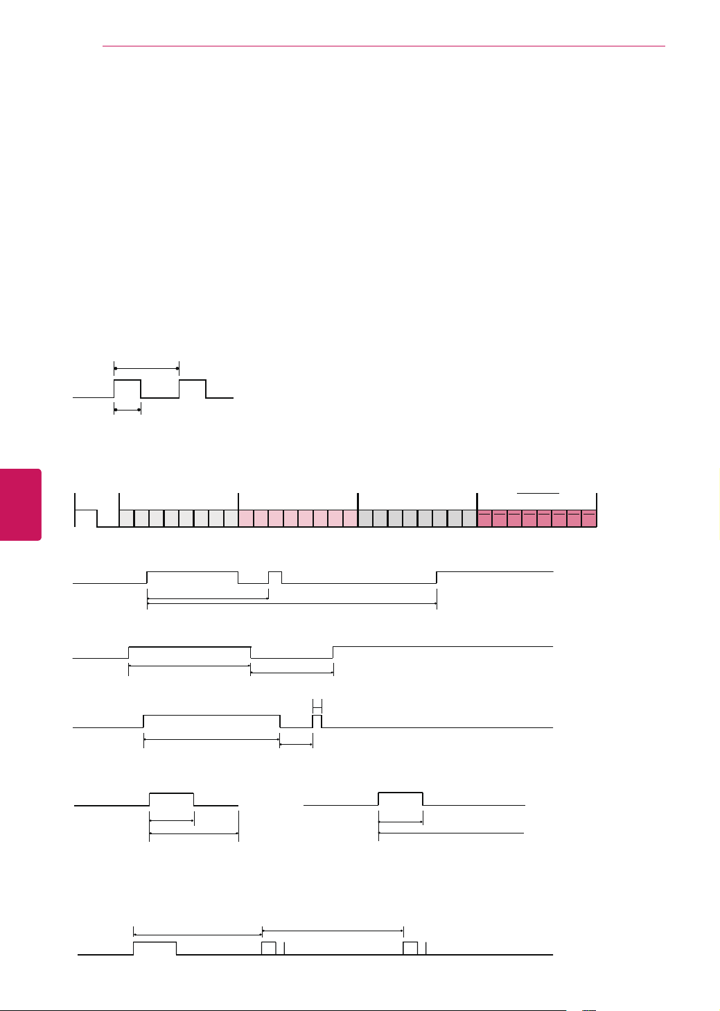
Output waveform
Single pulse, modulated with 37.917kHz signal at 455kHz
T1
Tc
Frame configuration
1st frame
C0 C1 C2 C3 C4 C5 C6 C7 C0 C1 C2 C3 C4 C5 C6 C7 D0 D1 D2 D3 D4 D5 D6 D7 D0 D1 D2 D3 D4 D5 D6 D7
Lead code Low custom code High custom code Data code Data code
Repeat frame
Repeat code
Tf
Lead code
4.5 ms
9 ms
Repeat code
2.25 ms
9 ms
0.55 ms
Bit description
0.56 ms
1.12 ms
0.56 ms
2.24 ms
Bit “0” Bit “1”
Frame interval: Tf
The waveform is transmitted as long as a key is depressed.
Tf Tf
Tf=108ms @455KHz
3
ENG
ENGLISH
EXTERNAL CONTROL DEVICE SETUP
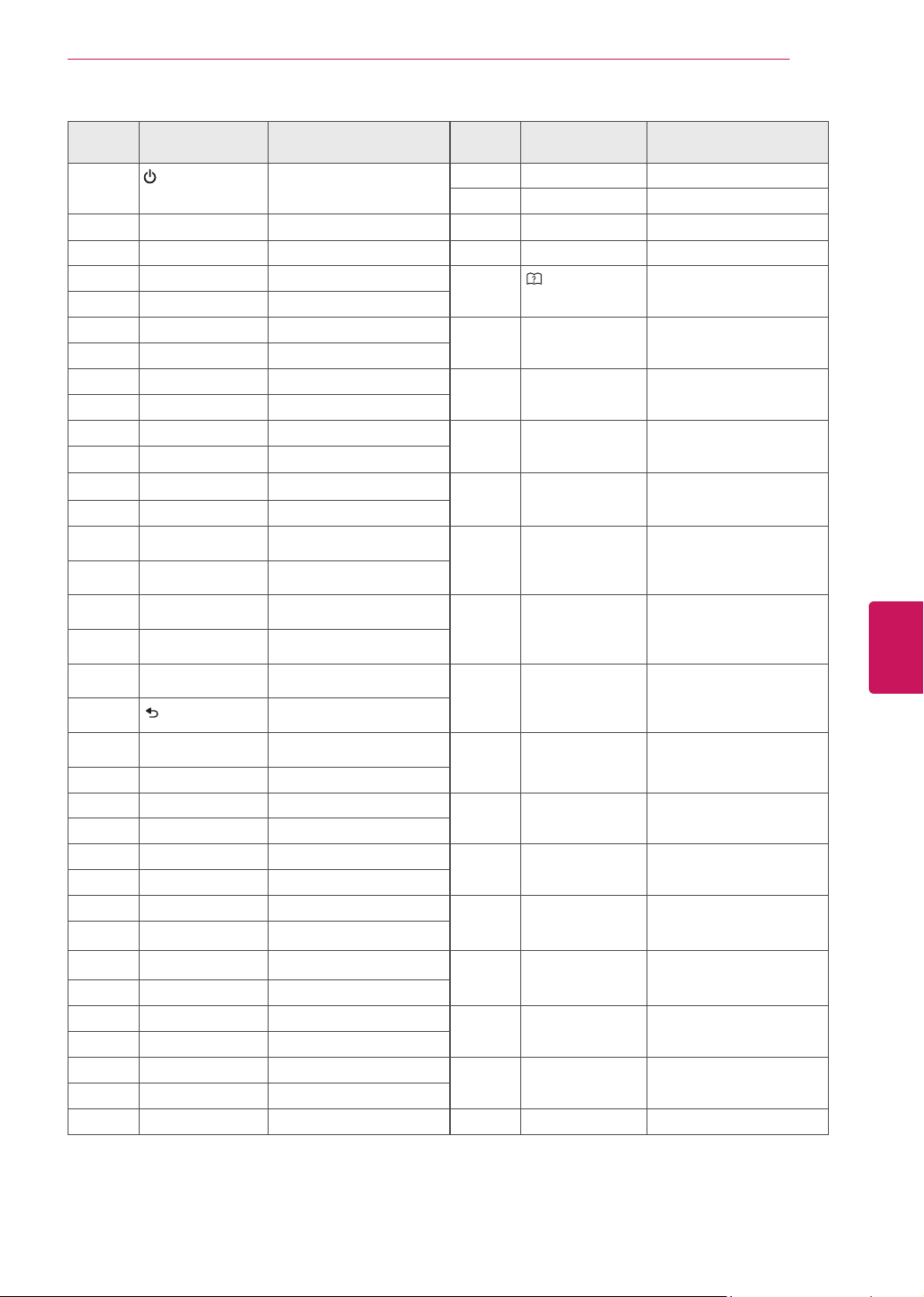
08
(POWER) Remote control Button
(Power On/Off)
0F TV Remote control Button
DC 3D Remote control Button
42
Q.MENU/MY APPS
Remote control Button 5B EXIT Remote control Button
43 SETTINGS Remote control Button 7C HOME Remote control Button
0B INPUT Remote control Button 7A
(User-Guide)
Remote control Button
10 - 19 Number Key 0-9 Remote control Button
4C - (Dash)/LIST Remote control Button D6 TV Discrete IR Code
(TV Input Selection)
1A FLASHBK Remote control Button
09 MUTE Remote control Button C4 POWER ON Discrete IR Code
(Only Power Off)
02 VOL + Remote control Button
03 VOL - Remote control Button C5 POWER OFF Discrete IR Code
(Only Power Off)
00
CH
Remote control Button
01
CH
Remote control Button 5A AV Discrete IR Code
(AV Input Selection)
1E FAV/MARK Remote control Button
40
Remote control Button BF COMPONENT1 Discrete IR Code
(Component1 Input
Selection)
41
Remote control Button
07
Remote control Button D4 COMPONENT2 Discrete IR Code
(Component2 Input
Selection)
06
Remote control Button
44 OK Remote control Button D5 RGB-PC Discrete IR Code
(RGB-PC Input Selection)
28
REC
(BACK)
Remote control Button
79 RATIO Remote control Button CE HDMI1 Discrete IR Code
(HDMI1 Input Selection)
BA
yy
(FREEZE) Remote control Button
95
ENERGY SAVING
Remote control Button CC HDMI2 Discrete IR Code
(HDMI2 Input Selection)
7E SIMPLINK Remote control Button
AA INFO Remote control Button E9 HDMI3 Discrete IR Code
(HDMI3 Input Selection)
30 AV MODE Remote control Button
72 RED Remote control Button DA HDMI4 Discrete IR Code
(HDMI4 Input Selection)
71 GREEN Remote control Button
63 YELLOW Remote control Button 76 Ratio 4:3 Discrete IR Code
(Only 4:3 Mode)
61 BLUE Remote control Button
B1
n
Remote control Button 77 Ratio 16:9 Discrete IR Code
(Only 16:9 Mode)
B0
Remote control Button
BA
yy
Remote control Button AF Ratio Cinema
Zoom
Discrete IR Code
(Only Cinema Zoom Mode)
8E
Remote control Button
8F
Remote control Button
Use the feature depending on your model.
4
ENG
ENGLISH
EXTERNAL CONTROL DEVICE SETUP
EXTERNAL CONTROL DEVICE SETUP
RS-232C Setup
Connect the RS-232C (serial port) input jack to
an external control device (such as a computer or
an A/V control system) to control the product’s
functions externally.
Connect the serial port of the control device to the
RS-232C jack on the product back panel.
NOTE
RS-232C on this TV is intended to be used
with third party RS-232C control hardware
and software. The instructions below
are provided to help with programming
software or to test functionality using telenet
software. RS-232C connection cables are not
supplied with the product.
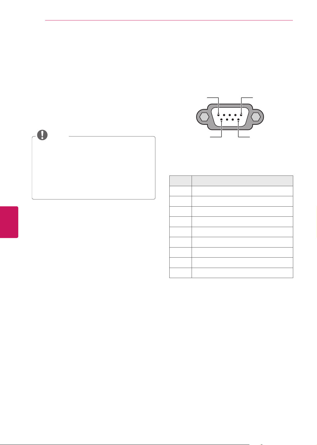
Type of connector;
D-Sub 9-Pin Male
1 5
6 9
RS-232C IN
(CONTROL & SERVICE)
1 No connection
2 RXD (Receive data)
3 TXD (Transmit data)
4 DTR (DTE side ready)
5 GND
6 DSR (DCE side ready)
7 RTS (Ready to send)
8 CTS (Clear to send)
9 No Connection
5
ENG
ENGLISH
EXTERNAL CONTROL DEVICE SETUP
RS-232C configurations
7-Wire Configuration
(Serial female-female NULL modem cable)
3-Wire Configurations(Not standard)
Set ID
Set ID number.
?
• Language
• Caption :Off
• ISMMethod :Normal
• Pointer
• BalloonHelp:On
• InitialSetting
• SetID :1
OPTION
1
Press
to access the main menu.
2
Press the Navigation buttons to scroll to
and press
.
3
Press the Navigation buttons to scroll to
and press
.
4
Press the Navigation buttons to scroll to
and press
.
5
Scroll left or right to select a set ID number and
select
. The adjustment range is 1-99.
6
When you are finished, press
.
*Real data mapping
0 : Step 0
…
A : Step 10 (SET ID 10)
…
F : Step 15 (SET ID 15)
10 : Step 16 (SET ID 16)
…
63 : Step 99 (SET ID 99)
64 : Step 100

6
ENG
ENGLISH
EXTERNAL CONTROL DEVICE SETUP
Command reference list
Communication Parameters
Baud rate: 9600 bps (UART)
Data length: 8 bits
Parity : None
Stop bit: 1 bit
Communication code: ASCII code
Use a crossed (reverse) cable.
01. Power k a 00 - 01 14. Balance k t 00 - 64
02. Input Select x b (See p.8)
15. 3D (For 3D
TV)
x t (See p.9)
03. Aspect
Ratio
k c (See p.8)
16. Color
Temperature
x u 00 - 64
04. Screen
Mute
k d 00 - 01
17.Extended
3D (For 3D TV)
x v (See p.9)
05. Volume
Mute
k e 00 - 01
18. ISM
Method
j p (See p.9)
06. Volume
Control
k f 00 - 64
19. Energy
Saving
j q (See p.9)
07. Contrast k g 00 - 64
20. Auto
Configuration
j u (See p.10)
08. Brightness k h 00 - 64
22. Channel
Add/Del
m b 00 - 01
09. Color k i 00 - 64 23. Key m c (See p.10)
10. Tint k j 00 - 64
11. Sharpness k k 00 - 32
12. OSD Select k l 00 - 01
13. Remote
Control Lock
Mode
k m 00 - 01
21. Channel
Tuning
m a
physical
program
high
major
program
low
major low minor high minor low attribute

7
ENG
ENGLISH
EXTERNAL CONTROL DEVICE SETUP
Transmission / Receiving protocol
Transmission
[Command 1] : First command to control the set.(j, k, m or x)
[Command 2] : Second command to control the set.
[Set ID] : You can adjust the set ID to choose desired set ID number in Option menu. Adjustment range is
1~ 99. When selecting Set ID ‘0’, every connected the set is controlled. Set ID is indicated as decimal (1~
99) on menu and as Hexa decimal (0x0~ 0x63) on transmission /receiving protocol.
[DATA] : To transmit the command data.
Transmit the ‘FF’ data to read status of command.
[Cr] : Carriage Return
ASCII code ‘0x0D’
[ ] : ASCII code ‘space (0x20)’
* In this model, set will not send the status during the standby mode.
OK Acknowledgement
The set transmits ACK (acknowledgement) based on this format when receiving normal data. At this time,
if the data is data read mode, it indicates present status data. If the data is data write mode, it returns the
data of the PC computer.
* In this model, set will not send the status during the standby mode.
* Data Format
[Command 2] : Use as command.
[Set ID] : Use the small character, if set ID is 10, it will send the ‘0’, ‘a’.
[DATA] : Use the small character, if data is 0 x ab, it will send the ‘a’, ‘b’.
[OK] : Use the large character.
Error Acknowledgement
The set transmits ACK (acknowledgement) based on this format when receiving abnormal data from non-
viable functions or communication errors.
Data01: Illegal Code
Data02: Not supported function
Data03: Wait more time
* In this model, set will not send the status during the standby mode.
* Data Format
[Command 2] : Use as command.
[Set ID] : Use the small character, if set ID is 10, it will send the ‘0’, ‘a’.
[DATA] : Use the small character, if data is 0 x ab, it will send the ‘a’, ‘b’.
[NG] : Use the large character

8
ENG
ENGLISH
EXTERNAL CONTROL DEVICE SETUP
To control Power On/Off of the set.
Transmission [k][a][ ][Set ID][ ][Data][Cr]
Data 00: Power Off Data 01: Power On
Acknowledgement [a][ ][Set ID][ ][OK/NG][Data][x]
* In a like manner, if other functions transmit ‘FF’
data based on this format, Acknowledgement data
feedback presents status about each function.
* Note: In this model, set will send the Acknowledge
after power on processing completion.
There might be a time delay between command and
acknowledge.
To select input source for set.
Transmission [x][b][ ][Set ID][ ][Data][Cr]
Data 00: DTV (Antenna) Data 01: DTV (Cable)
Data 10: Analog (Antenna) Data 11: Analog (Cable)
Data 20: AV or AV1 Data 21: AV2
Data 40: Component1 Data 41: Component2
Data 42: Component3 Data 60: RGB-PC
Data 90: HDMI1 Data 91: HDMI2
Data 92: HDMI3 Data 93: HDMI4
Acknowledgement [b][ ][Set ID][ ][OK/NG][Data][x]
* Use the feature depending on your model.
To adjust the screen format.
Transmission [k][c][ ][Set ID][ ][Data][Cr]
Data 01: 4:3 Data 09: Just scan
Data 02: 16:9 Data 10: Cinema Zoom 1
Data 04: Zoom
Data 06: Set by program
…
Data 1F: Cinema Zoom16
Acknowledgement [c][ ][Set ID][ ][OK/NG][Data][x]
To select screen mute on/off.
Transmission [k][d][ ][Set ID][ ][Data][Cr]
Data 00:
Screen mute off (Picture on), Video-out Mute off
Data 01: Screen mute on (Picture off)
Data 10: Video-out Mute on
Acknowledgement [d][ ][Set ID][ ][OK/NG][Data][x]
* In case of Video-out Mute on only,
TV will display On
Screen Display (OSD). But, in case of screen mute on,
TV will not display On Screen Display (OSD).
To control volume mute on/off.
You can also adjust mute using the MUTE button on
remote control.
Transmission [k][e][ ][Set ID][ ][Data][Cr]
Data 00: Volume mute on (Volume off)
Data 01: Volume mute off (Volume on)
Acknowledgement [e][ ][Set ID][ ][OK/NG][Data][x]
To adjust volume.
You can also adjust volume with the volume buttons on
remote control.
Transmission [k][f][ ][Set ID][ ][Data][Cr]
Data Min: 00 ~ Max: 64 (*transmit by Hexadecimal code)
*Refer to “Real data mapping”.
Acknowledgement [f][ ][Set ID][ ][OK/NG][Data][x]
To adjust screen contrast.
You can also adjust contrast in the PICTURE menu.
Transmission [k][g][ ][Set ID][ ][Data][Cr]
Data Min: 00 ~ Max: 64 (*transmit by Hexadecimal code)
*Refer to “Real data mapping”.
Acknowledgement [g][ ][Set ID][ ][OK/NG][Data][x]
To adjust screen brightness.
You can also adjust brightness in the PICTURE menu.
Transmission [k][h][ ][Set ID][ ][Data][Cr]
Data Min: 00 ~ Max: 64 (*transmit by Hexadecimal code)
*Refer to “Real data mapping”.
Acknowledgement [h][ ][Set ID][ ][OK/NG][Data][x]
To adjust screen color.
You can also adjust color in the PICTURE menu.
Transmission [k][i][ ][Set ID][ ][Data][Cr]
Data Min: 00 ~ Max: 64 (*transmit by Hexadecimal code)
*Refer to “Real data mapping”.
Acknowledgement [i][ ][Set ID][ ][OK/NG][Data][x]
To adjust screen tint.
You can also adjust tint in the PICTURE menu.
Transmission [k][j][ ][Set ID][ ][Data][Cr]
Data Red: 00 ~ Green: 64 (*transmit by Hexadecimal
code)
*Refer to “Real data mapping”.
Acknowledgement [ j ][ ][Set ID][ ][OK/NG][Data][x]
To adjust screen sharpness.
You can also adjust sharpness in the PICTURE menu.
Transmission [k][k][ ][Set ID][ ][Data][Cr]
Data Min: 00 ~ Max: 32 (*transmit by Hexadecimal code)
*Refer to “Real data mapping”.
Acknowledgement [k][ ][Set ID][ ][OK/NG][Data][x]

9
ENG
ENGLISH
EXTERNAL CONTROL DEVICE SETUP
To select OSD (On Screen Display) on/off.
Transmission [k][l][ ][Set ID][ ][Data][Cr]
Data 00: OSD off Data 01: OSD on
Acknowledgement [l][ ][Set ID][ ][OK/NG][Data][x]
To lock the remote control and the front panel controls
on the set.
Transmission [k][m][ ][Set ID][ ][Data][Cr]
Data 00: Lock off Data 01: Lock on
Acknowledgement [m][ ][Set ID][ ][OK/NG][Data][x]
If you’re not using the remote control and front panel
controls on the Monitor set, use this mode. When main
power is on/off, remote control lock is released.
If Key Lock is on in the standby mode, TV will not turn on
by POWER button of remote control and on the TV.
To adjust balance.
You can also adjust balance in the AUDIO menu.
Transmission [k][t][ ][Set ID][ ][Data][Cr]
Data Min: 00 ~ Max: 64 (*transmit by Hexadecimal code)
*Refer to “Real data mapping”.
Acknowledgement [t][ ][Set ID][ ][OK/NG][Data][x]
To change 3D mode for TV.
Transmission [x][t][ ][Set ID][ ][Data01]
[ ][Data02][ ][Data03][ ][Data04][Cr]
Data1
00: 3D On 01: 3D Off
02: 3D to 2D 03: 2D to 3D
Data2
00: Top and Bottom 01: Side by Side
02: Check Board 03:
Single Frame Sequential
04: Column interleaving 05: Row interleaving
Data3
00: Right to Left 01: Left to Right
Data4
3D Depth: Min : 00 ~ Max : 14
(*transmit by Hexadecimal code)
*If data1 is 01(3D Off) , data2 , data3 , data4 have no
meaning.
* If data1 is 02(3D to 2D), data2, data3 and data4 have no
meaning.
* If data1 is 03(2D to 3D), data2 and data3 have no
meaning.
Data 01 Data 02 Data 03 Data 04
00 o o x
01 x x x
02 x x x
03 x x o
x : Don’t care
Acknowledgement [t][ ][OK][Data01][Data02]
[Data03][Data04][x][t][ ][NG][Data01][x]
To adjust color temperature.
You can also adjust color temperature in the PICTURE
menu.
Transmission [x][u][ ][Set ID][ ][Data][Cr]
Data Min: 00 ~ Max: 64 (*transmit by Hexadecimal code)
*Refer to “Real data mapping”.
Acknowledgement [u][ ][Set ID][ ][OK/NG][Data][x]
To change 3D option for TV. Use the feature depending
on your model.
Transmission [x][v][ ][Set ID][ ][Data01][ ][Data02][Cr]
Data1: 3D option
00: 3D Picture Correction
01: 3D Depth
02: 3D Viewpoint
07: 3D Sound Zooming
08: Normal Image View
09: 3D Mode
Data2: It has own range for each 3D option determined
by Data1.
1) When Data1 is 00
00: Right to Left
01: Left to Right
2) When Data1 is 01
Data Min: 00 ~ Max: 14 (*transmit by Hexadecimal code)
3) When Data1 is 02
Data Min: 00 ~ Max: 14 (*transmit by Hexadecimal code)
4) When Data1 is 07
00: Off
01: On
5) When Data1 is 08
00: Off
01: On
6) When Data1 is 09
00: Standard
01: Sports
02: Cinema
03: Extreme
04: Manual
Acknowledgement [v][ ][OK][Data01][Data02][x]
[v][ ][NG][Data01][x]
* Use the feature depending on your model.
To avoid having a fixed image remain on screen.
Transmission [j][p][ ][Set ID][ ][Data][Cr]
Data 02: Orbiter
08: Normal
20: Color Wash
Acknowledgement [p][ ][Set ID][ ][OK/NG][Data][x]
To control the energy saving function.
Transmission [ j ][q][ ][Set ID][ ][Data][Cr]
Data 00: off

10
ENG
ENGLISH
EXTERNAL CONTROL DEVICE SETUP
01: Minimum
02: Medium
03: Maximum
04: Intelligent Sensor
05: Screen off
Acknowledgement [q][ ][Set ID][ ][OK/NG][Data][x]
To adjust picture position and minimize image shaking
automatically. Auto configuration only works in RGB-PC
mode.
Transmission [ j ][u][ ][Set ID][ ][Data][Cr]
Data 01: To set
Acknowledgement [u][ ][Set ID][ ][OK/NG][Data][x]
To tune channel to following physical/major/minor
number.
(This feature is not available for all models.)
Transmission [m][a][ ][Set ID][ ][Data00][ ][Data01]
[ ][Data02][ ][Data03][ ][Data04][ ][Data05][Cr]
Digital channels have a Physical, Major, and Minor
channel number. The Physical number is the actual
digital channel number, the Major is the number that the
channel should be mapped to, and the Minor is the sub-
channel. Since the ATSC tuner automatically maps the
channel to the Major number, the Physical number is not
required when sending a command.
Data 00: Physical Channel Number
NTSC air: 02~45, NTSC cable: 01, 0E~7D
ATSC air: 01~45, ATSC cable: 01~87
Data 01 & 02: Major Channel Number
Data 01: High byte Data 02: Low byte
Two bytes are available for the Major and Minor,
normally only the second byte is used.
Data 03 & 04: Minor Channel Number
Not needed for NTSC.
The table lists the binary code which must be converted
to Hexadecimal before sending. For example:
The binary code to tune the sub source to an NTSC cable
channel is “1000 0001”, which translates to “81” in
Hex.
* 7th bit : For which source do you want to change
the channel.
* 6th bit: Use a two part or one part channel. Most
cases just use 0 since it’s ignored when using
NTSC.
* 5th bit: Use 0 with NTSC since it can only use
the physical channel number. Normally use 1 for
ATSC since most times it doesn’t matter what the
physical number is.
* 4th bit: Set to 0.
* 3-0 bits: Choose signal type.
* Tune Command Examples:
1. Tune to the analog (NTSC) cable channel 35.
Data 00 = Physical of 35 = 23
Data 01 & 02 = No Major = 00 00
Data 03 & 04 = No Minor = 00 00
Data 05 = 0000 0001 in binary = 01
Total = ma 00 23 00 00 00 00 01
2. Tune to the digital (ATSC) local channel 30-3.
Data 00 = Don’t know Physical = 00
Data 01 & 02 = Major is 30 = 00 1E
Data 03 & 04 = Minor is 3 = 00 03
Data 05 = 0010 0010 in binary = 22
Total = ma 00 00 00 1E 00 03 22
To add and delete the channels.
Transmission [m][b][ ][Set ID][ ][Data][Cr]
Data 00: Channel Delete Data 01: Channel Add
Acknowledgement [b][ ][Set ID][ ][OK/NG][Data][x]
To send IR remote key code.
Transmission [m][c][ ][Set ID][ ][Data][Cr]
See page 3.
Acknowledgement [c][ ][Set ID][ ][OK/NG][Data][x]
When TV is in the standby mode, TV will turn on by
POWER button of remote control only.
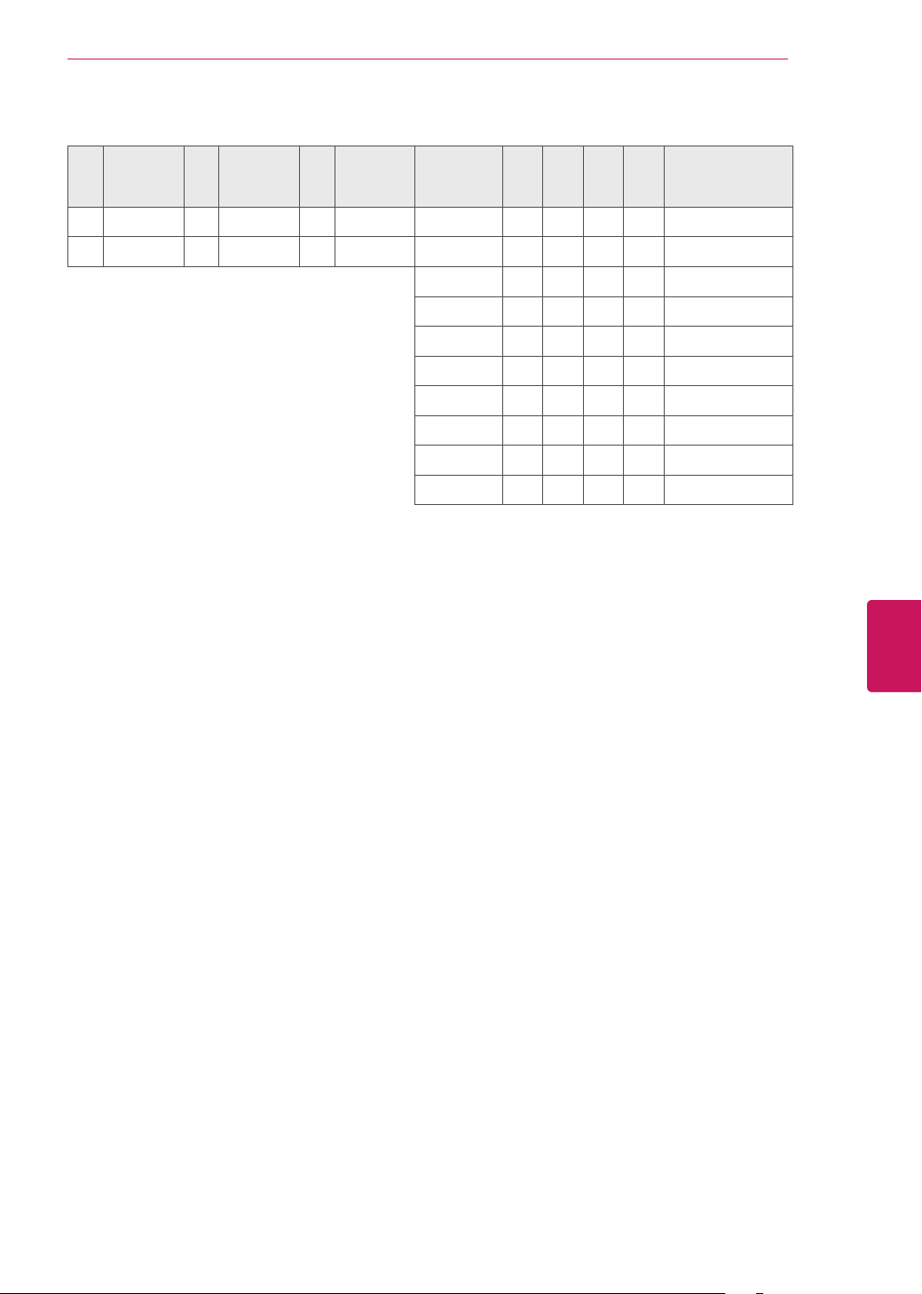
11
ENG
ENGLISH
EXTERNAL CONTROL DEVICE SETUP
* Table List (Channel Tuning)
0 Main 0 Two 0 Use x 0 0 0 0 NTSC Air
1 Sub 1 One 1 No Use x 0 0 0 1 NTSC Cable
x 0 0 1 0 ATSC Air
x 0 0 1 1 ATSC Cable_std
x 0 1 0 0 ATSC Cable_hrc
x 0 1 0 1 ATSC Cable_irc
x 0 1 1 0 ATSC cable_auto
x 0 1 1 1 Reserved
x x x x x ...
x 1 1 1 1 Reserved