
5918 A 08.17
INSTALLATION GUIDE
NZ AU GB IE
DD60DI & DD60DHI models
DOUBLE DISHDRAWER
TM
DISHWASHER

1

2
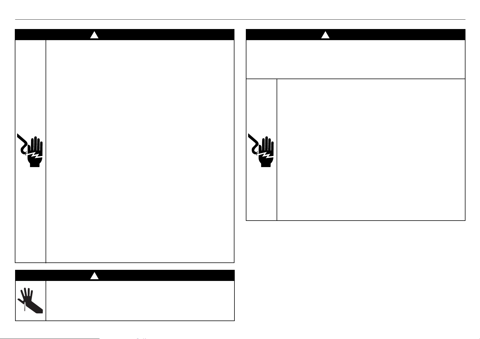
1 SAFETY AND WARNINGS
WARNING!
Electrical shock hazard
Before installing the dishwasher, remove the
house fuse or open the circuit breaker.
This appliance must be earthed. In the event
of a malfunction or breakdown, earthing will
reduce the risk of electric shock by providing
a path of least resistance for electric current.
This appliance is equipped with a cord having
an equipment-earthing conductor and an
earthing plug. The plug must be plugged into
an appropriate outlet that is installed and
earthed in accordance with all local codes and
ordinances.
WARNING- Improper connection of the
equipment-earthing conductor can result in a
risk of electric shock. Check with a qualified
electrician or service representative if you are
in doubt as to whether the appliance is properly
earthed.
Do not modify the power supply plug provided
with the appliance - if it will not fit the outlet,
have a proper outlet installed by a qualified
electrician. Do not use an extension cord,
adapter plug or multiple outlet box.
Failure to follow this advice may result in
electrical shock or death.
WARNING!
Electrical Shock Hazard
WARNING: To reduce the risk of electrical
shock, fire, or injury to persons, the installer
must ensure that the dishwasher is completely
enclosed at the time of installation.
Before fitting the front panels and connecting
the integrated badges (where present), the
installer must ensure that the dishwasher is
disconnected from the power supply.
After installing the front panels, the installer
must ensure that the following components
are electrically earthed: the panel bracket, the
integrated badge (where present) and any
custom metal component (e.g. handle) that
extends past the rubber seal.
Failure to follow these warnings may result in
electrical shock, injury or fire.
WARNING!
Cut Hazard
Take care - panel edges are sharp.
Failure to use caution could result in injury or
cuts.
! !
!
Fitting integrated front panels requires access to
electrical service areas.
This work must be performed and certified by a
qualified electrical service technician.

3
1 SAFETY AND WARNINGS
IMPORTANT SAFETY INSTRUCTIONS
●
Installation of this dishwasher requires basic
mechanical and electrical skills.
●
Be sure to leave these Instructions with the Customer.
●
Installation must comply with your local building and
electricity regulations.
●
At the completion of the dishwasher installation, the
Installer must perform the Final Checklist.
●
Remove all packaging materials supplied with the
dishwasher.
●
This dishwasher is manufactured for indoor use only.
●
Ensure all water connections are turned OFF. It is the
responsibility of the plumber and electrician to ensure
that each installation complies with all Codes and
Regulations.
●
The dishwasher MUST be installed to allow for future
removal from the enclosure if service is required.
●
The switched power outlet must be outside the
dishwasher cavity, so that it is accessible after
installation.
●
Care should be taken when the appliance is installed
or removed to reduce the likelihood of damage to the
power supply cord and hoses.
●
If the dishwasher is to be relocated from one
installation to another it must be kept upright to avoid
damage from water spillage.
●
Make sure only new hoses are used for connection
(supplied with the dishwasher). Old hoses should not
be reused.
●
Failure to install the dishwasher correctly could
invalidate any warranty or liability claims.
IMPORTANT SAFETY INSTRUCTIONS
●
Ensure the product is not plugged in when fitting
custom panels.
●
Installation of custom panels requires basic mechanical
and electrical skills.
●
Installation must comply with your local building and
electricity regulations.
●
Failure to install the custom panels correctly could
invalidate any warranty or liability claims.
IMPORTANT!
SAVE THESE INSTRUCTIONS
The models shown in this installation guide may not be available in all markets and are subject to change at any time. For current details about model and specification availability in your country, please go to our
website www.fisherpaykel.com or contact your local Fisher & Paykel dealer.
4
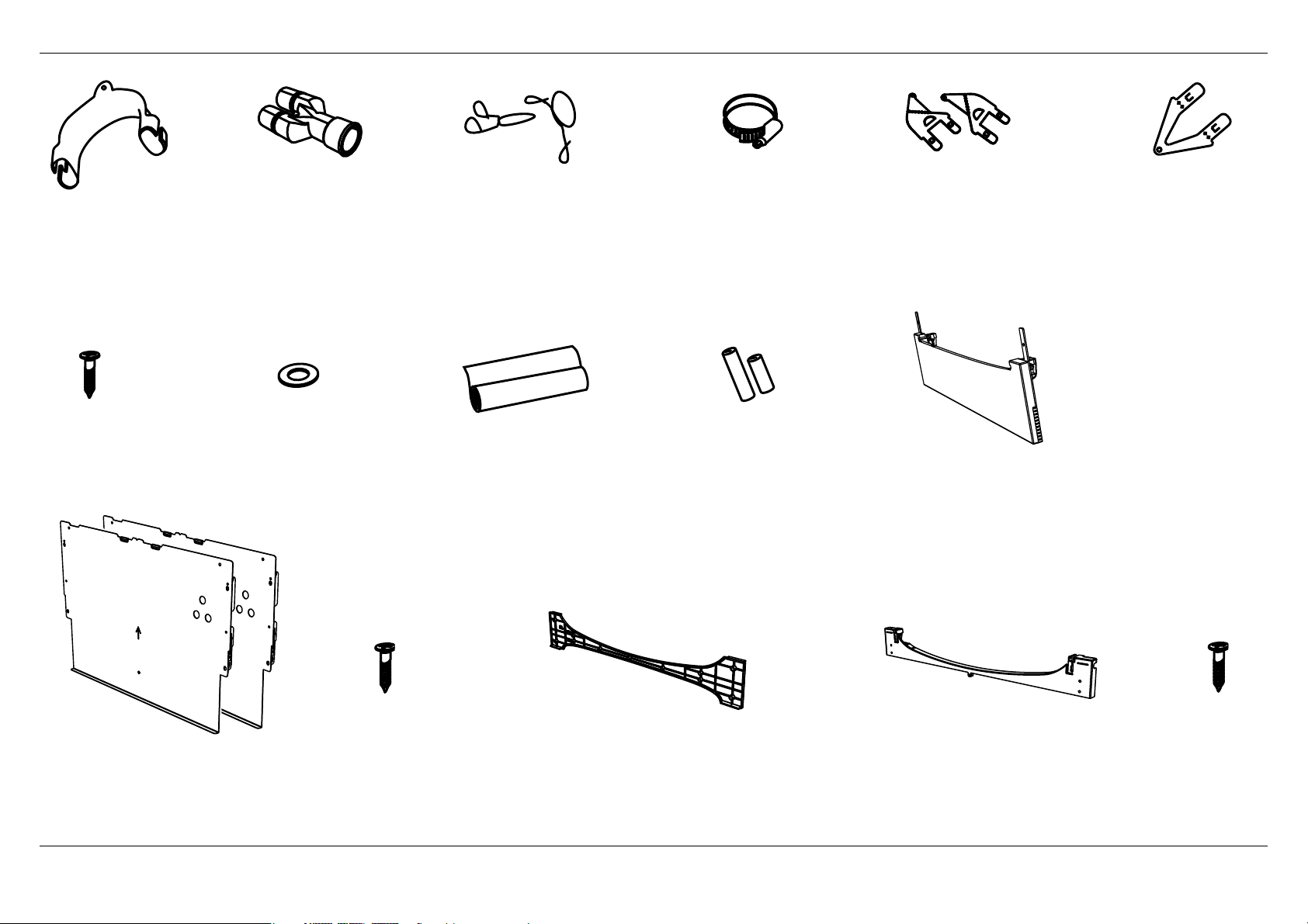
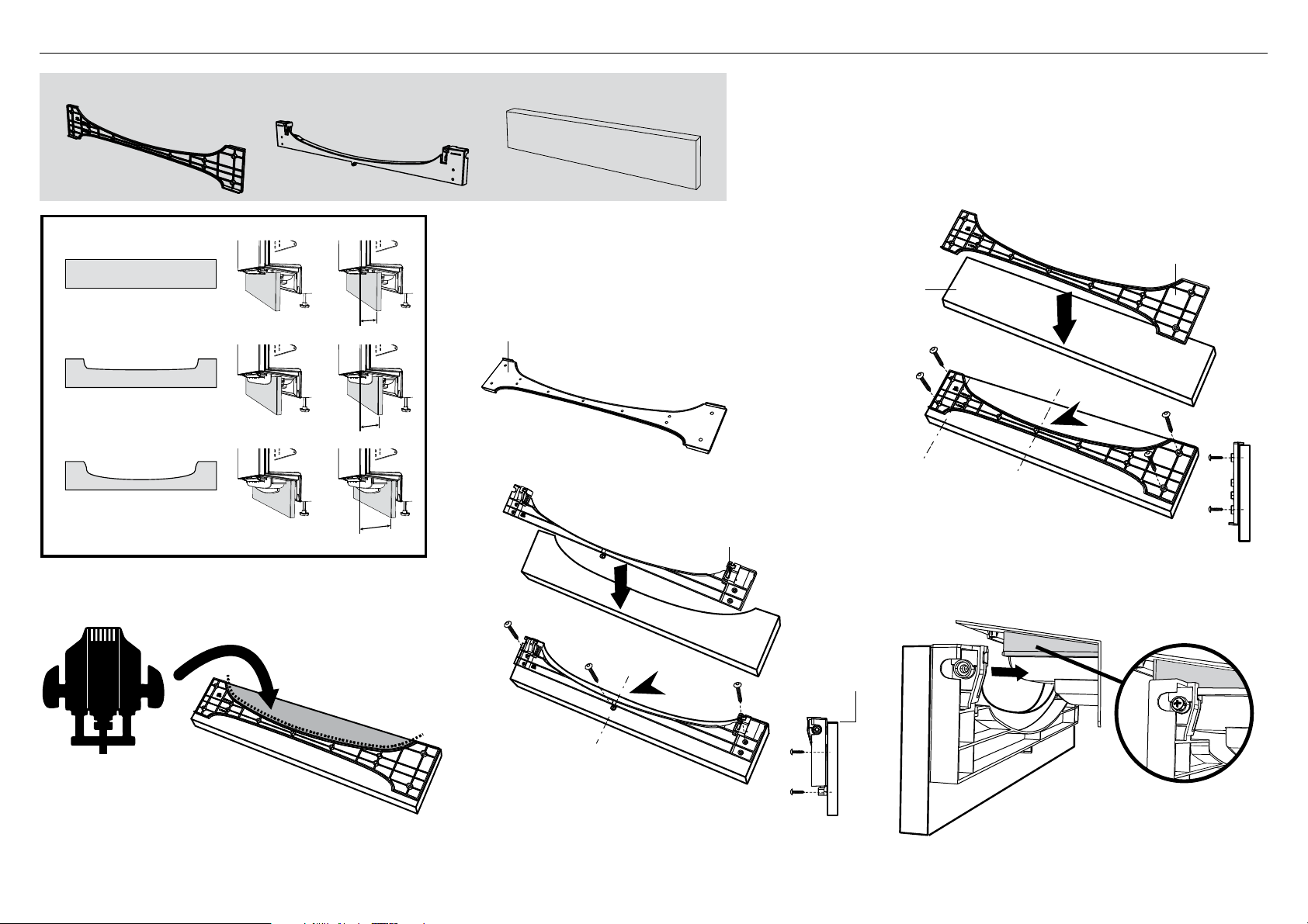
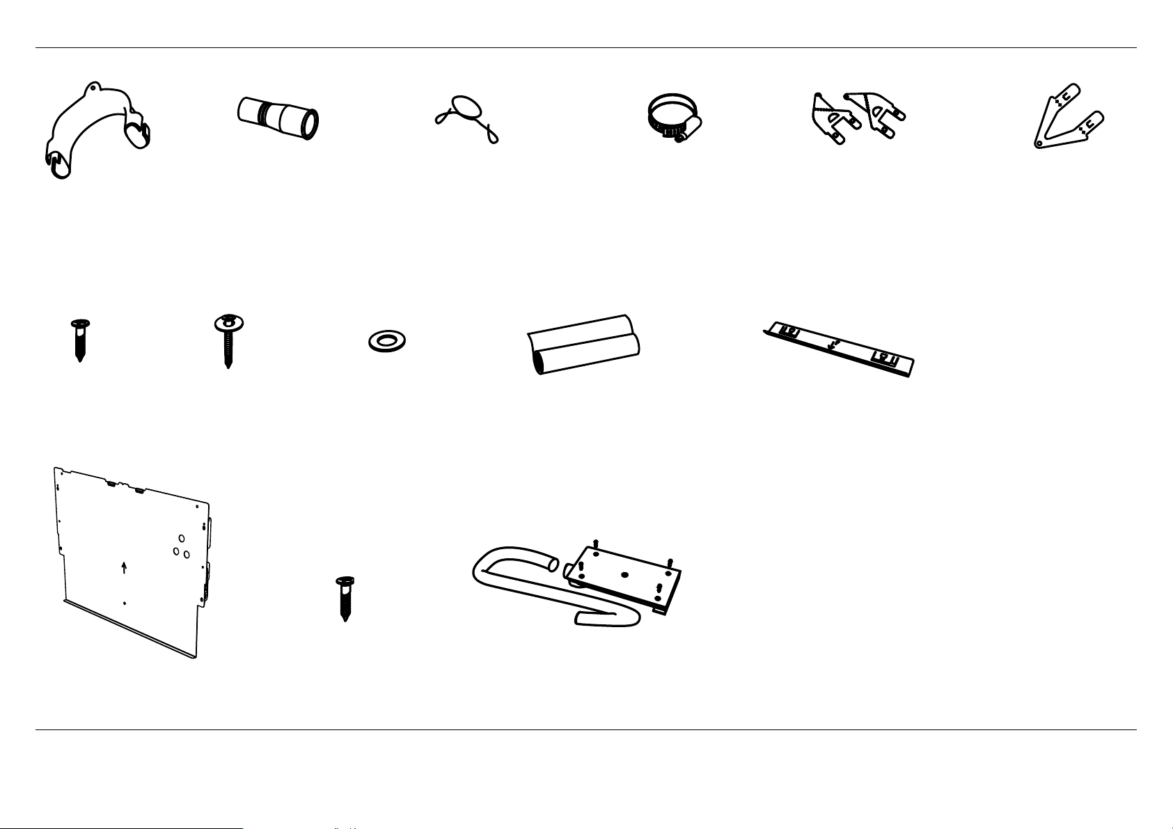
2 PARTS SUPPLIED
If the Drain hoses supplied are not long enough to reach your services, you must use a Drain Hose Extension Kit P/N 525798 which will extend the drain hoses by 3.6 m.
The kit is available from the nearest Fisher & Paykel Authorised Service Centre or our website.
Clamp (1)
(for securing
Drain hose joiner)
Wire clip (2)
(for securing
Drain hose joiner)
Phillips
16 mm
screws (9)
Drain hose
support (1)
Moisture protection
tape (1)
(to prevent moisture
damage to cabinetry)
Drain hose
joiner (1)
Top
mounting
brackets (2)
OPTIONAL
Prefinished toekick (1) Rubber washer
for inlet hose (1)
(comes already
fitted)
Hexagonal
socket for feet
adjustment (2)
(long & short)
Side mounting
bracket kit
(A and B) (2)
OPTIONAL
Panel bracket (2)
& Knock-to-Pause Module (2)
(shipped fixed to product)
Panel mounting
screws (12)
Toekick
mounting
screws (5)
Toekick mounting bracket (1)
(A custom toekick panel of any material
with thickness 9 - 19mm can be screwed
to the Toekick mounting bracket)
Toekick panel cutting template (1)
(To enable a custom toekick panel to be
cut to fit the product profile dependant
on the depth of the toekick )
5
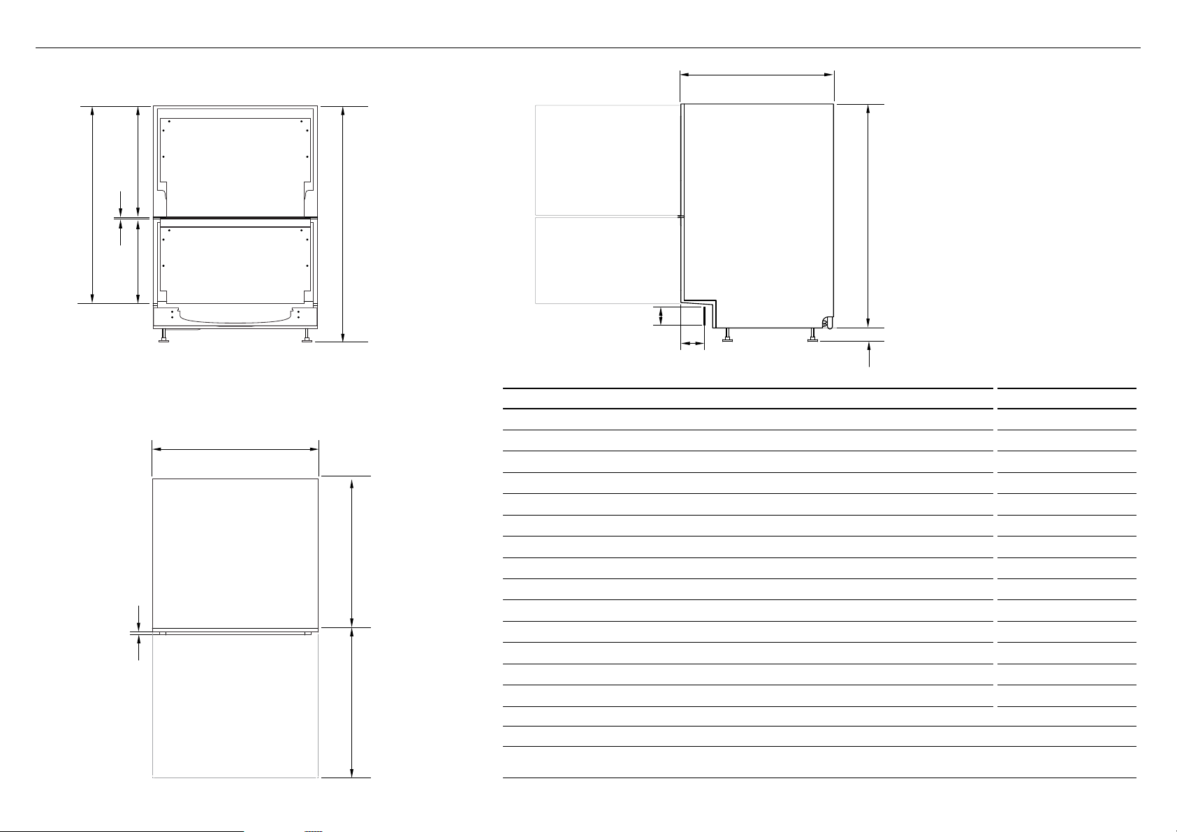
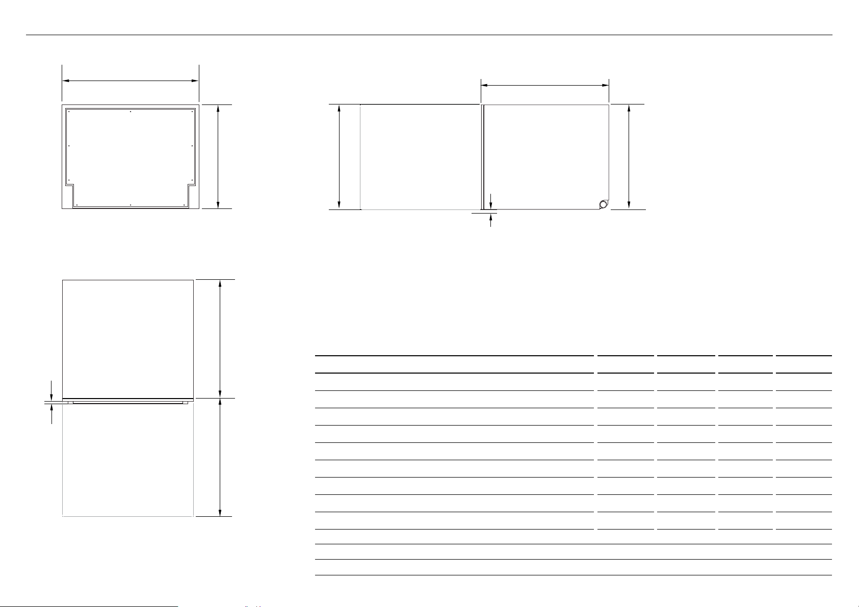
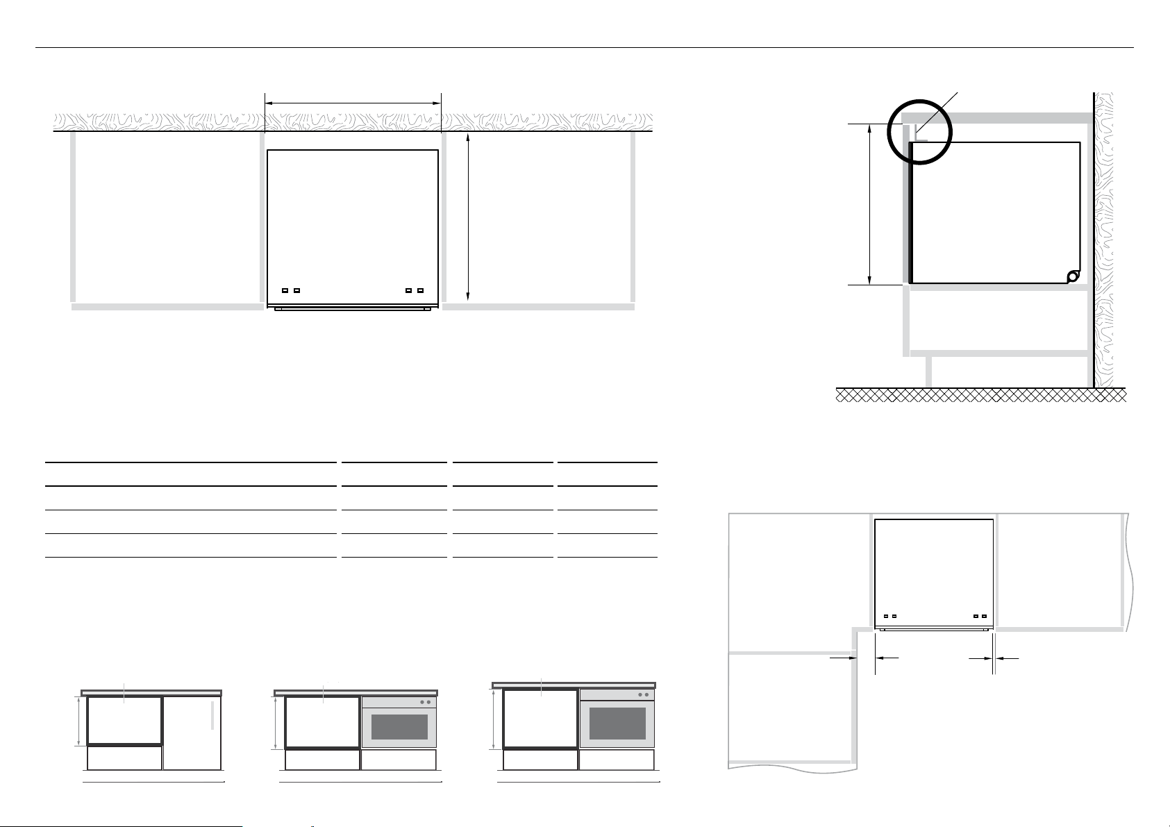
3 PRODUCT DIMENSIONS
B
D
N
E
A
G
H
I
J
C
F
M
L
K
PLAN
PROFILEFRONT
DD60DI
DD60DHI
PRODUCT DIMENSIONS MM
A
Overall height of product
1, 2
820-880
B
Overall width of product
599
C
Overall depth of product
3
571
D
Depth of chassis (to back of front drawer panel)
553
E
Depth of drawer front panel
16-20
F
Height of chassis
1
811
G
Height of drawer front panels
min. 717
H
Height of upper drawer front panel
min. 398
I
Height of lower drawer front panel
311-360
J
Ventilation gap between drawer front panels
8
K
Height of toekick (customisable)
58-118
L
Depth from front of drawer panel to front of toekick (adjustable)
4, 5
40-100
M
Height of leveling feet (adjustable)
2
9-69
N
Maximum extension of drawer
3
545
1
includes 2mm high bracket slots
2
depending on adjustment of leveling feet
3
assuming front panel thickness of 18mm
4
adjustable to match toekick recess on adjoining cabinetry
5
assuming custom toekick panel thickness of 18mm; if recess is between 50-84mm deep, the panel will need to be cut out
- see step ‘Custom panel calculations’
6
Q
P
O
R
S
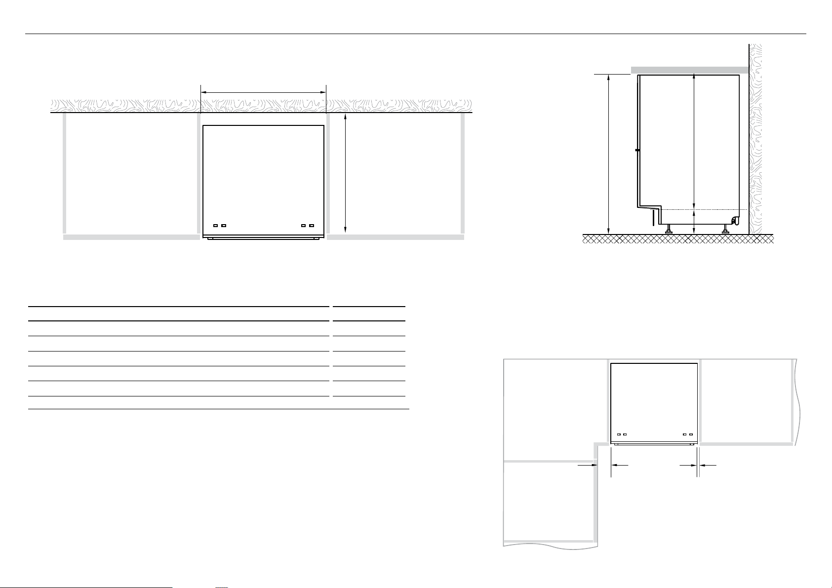
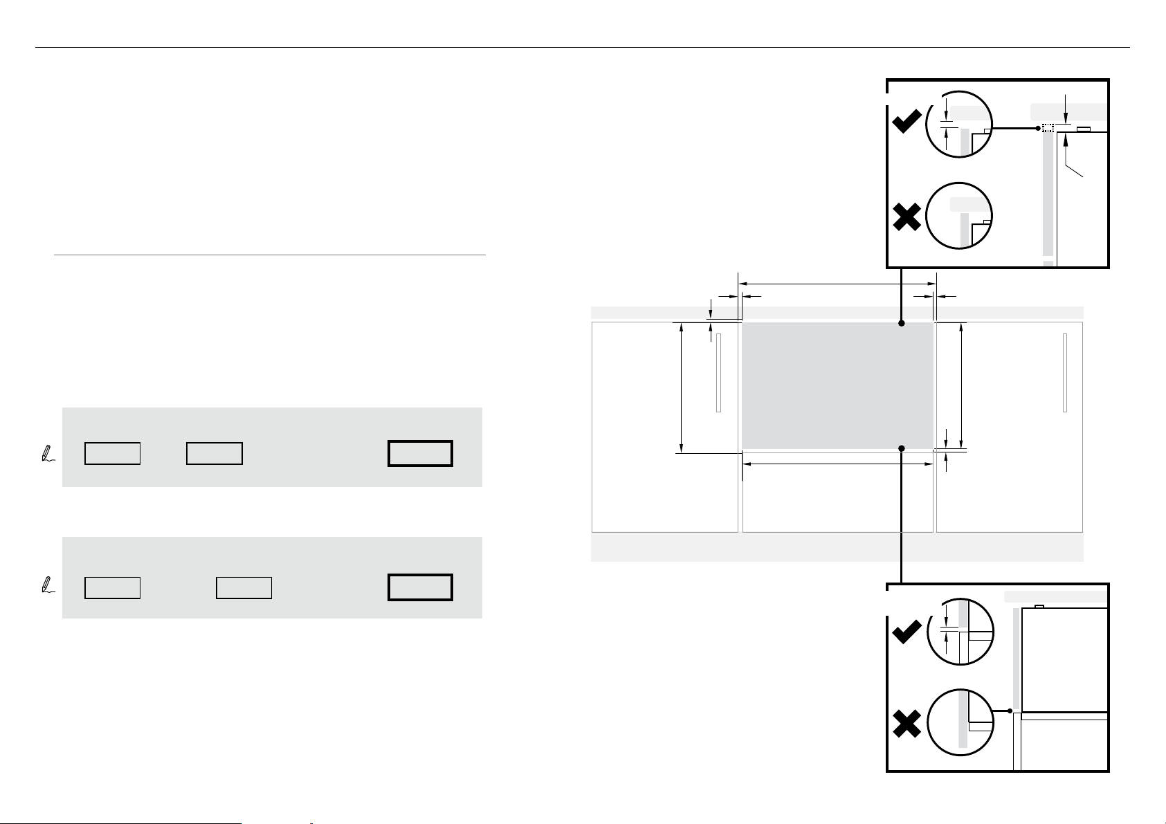
4 CABINETRY DIMENSIONS
Minimum clearances from adjacent cabinetry
min. 13 mm
clearance
from a corner
cupboard
Bracket slots
min. 2 mm
clearance
to adjacent
cupboard door
PROFILEPLAN
DD60DI
DD60DHI
CABINETRY DIMENSIONS MM
O
Inside height of cavity* min. 820
P
Inside width of cavity 600
Q
Inside depth of cavity min. 560
R
Recommended height of adjacent cabinet space 720
S
Height of toekick space* 100-160
* depending on adjustment of levelling feet
7
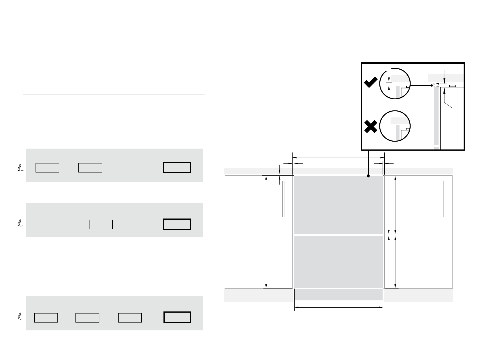
5 CUSTOM DRAWER PANEL CALCULATIONS
The following calculations assume the top of the upper panel is
aligned with the top of the adjacent cabinetry.
The final panel/cabinetry alignment is achieved by adjusting the feet:
WIDTH OF ALL PANELS
Measure A (the width between adjacent door/drawer fronts)
and write it in the first box below, then complete the equation.
HEIGHT OF THE UPPER PANEL
HEIGHT OF THE LOWER PANEL
Measure C (door/drawer height (or equivalent)) and write it in the
first box below, then complete the equation.
min. 2mm
Ventilation Gap (min. 8mm)
min. 2mm
min. 2mm
min. 2mm
WIDTH OF ALL PANELS
UPPER PANEL
LOWER PANEL
TOEKICK PANEL
HEIGHT OF
LOWER PANEL
HEIGHT OF
UPPER PANEL
C
A
B
A
B
C
Clearance to adjacent
cabinet front
(min. 2mm)
(0mm recommended)
(min. 311mm)
(min. 8mm)
(596 - 615mm)
Height of
Upper Panel
Upper Panel extension
Ventilation Gap
(min 717mm + B)
minimum
height
WIDTH OF PANEL
HEIGHT OF
UPPER PANEL
HEIGHT OF
LOWER PANEL
398mm
Note: The ‘upper panel extension’ B allows for the top of the upper
panel to extend above the chassis where required, however a
min. 2mm gap to the benchtop must be maintained.
Note: The ‘upper panel extension’ B
allows for the top of the upper panel to
extend above the chassis where required,
however a min. 2mm gap to
the benchtop must be maintained.
- 2x =
=
=
+
--
FRONT PANEL MATERIAL SPECIFICATIONS
●
16 - 20mm panel thickness
●
Adequately sealed to withstand moisture (50
O
C @ 80% RH)
Because of it being a hot and wet environment generally, the back and sides of the
panel should be completely sealed with a waterproof vapour barrier (ie polyurethane)
to prevent damage to the panel.
●
The back of the panel (including any integrated handle) should be completely flush
so that the seal between the panel and the rubber trim is maintained.
●
Installation outside these specs may result in condensation on cabinetry surfaces.
●
Maximum weight of each panel: 9kg
8
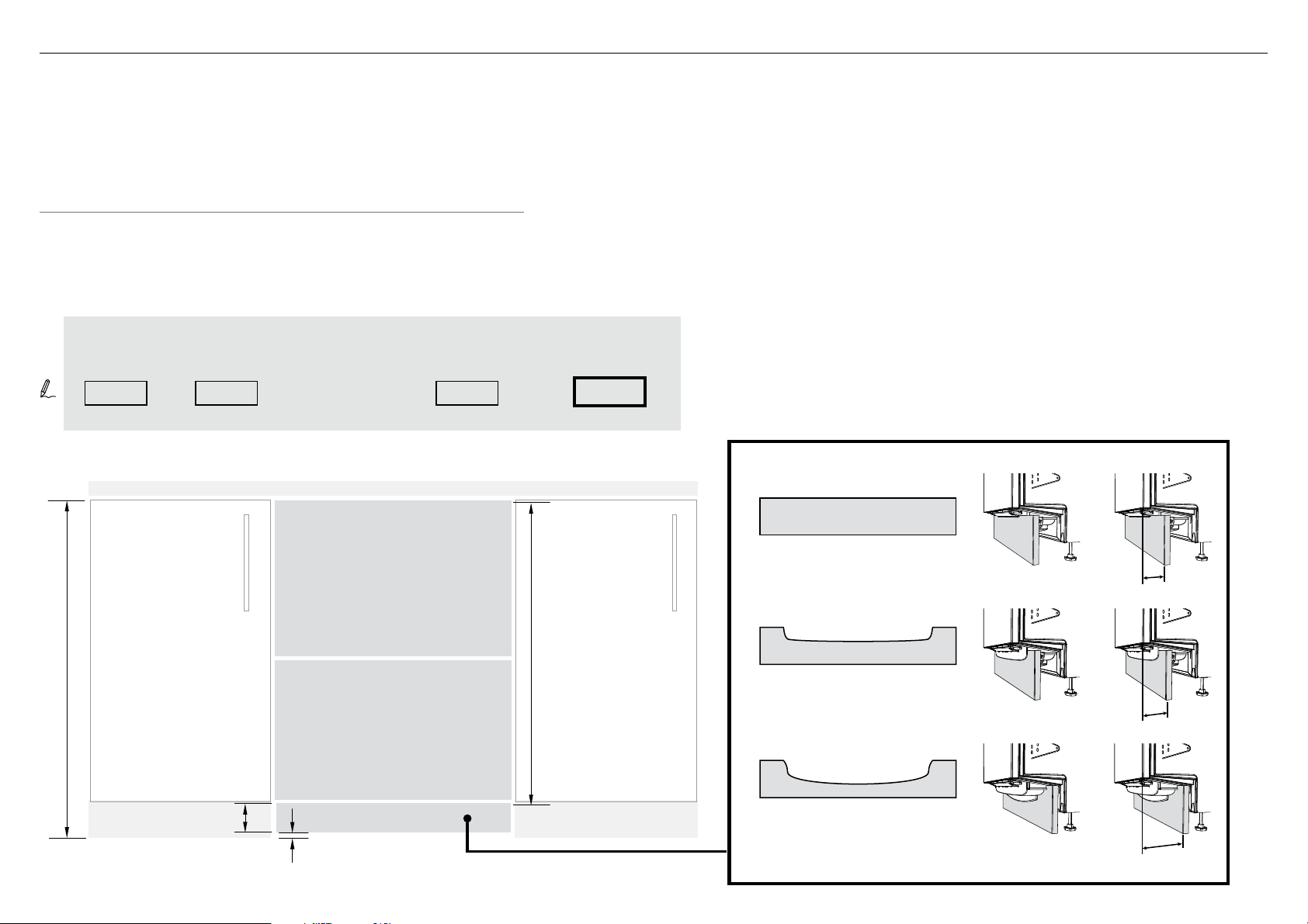
6 CUSTOM TOEKICK PANEL CALCULATIONS
HEIGHT OF THE TOEKICK PANEL
Measure D (height from the top of adjacent cabinet door fronts to the floor)
and write it in the first box below, then complete the equation.
Clearance to floor
(min. 12mm)
Toekick Depth
For a Toekick Depth 40mm
Depth is measured from FRONT of door panel
(assuming thickness ~18mm) to front face of
custom toekick panel
For a Toekick Depth 40-88mm
For a Toekick Depth 88-100mm
Toekick panel cutting template:
PROFILE A
Toekick panel cutting template:
PROFILE B
NO CUTOUT
HEIGHT OF
TOEKICK PANEL
D
750mm
40mm
40-88mm
88-100mm
B
D
(0mm recommended)
(min. 58mm)
(min. 12mm)
Upper Panel
extension
height from top
of product to
toekick panel
mounting point
Height from top
of product to
toekick panel
mounting point
Clearance to floor
HEIGHT OF
TOEKICK PANEL
750mm
=-- -
TOEKICK PANEL MATERIAL SPECIFICATIONS
●
min. 9mm panel thickness if using supplied screws
●
Adequately sealed to withstand moisture (50
O
C @ 80% RH)
●
You may choose to affix your custom toekick panel either by screwing
it or gluing it to the supplied mounting bracket.
CUSTOM TOEKICK PANEL
CUSTOM TOEKICK PANEL
CUSTOM TOEKICK PANEL

9
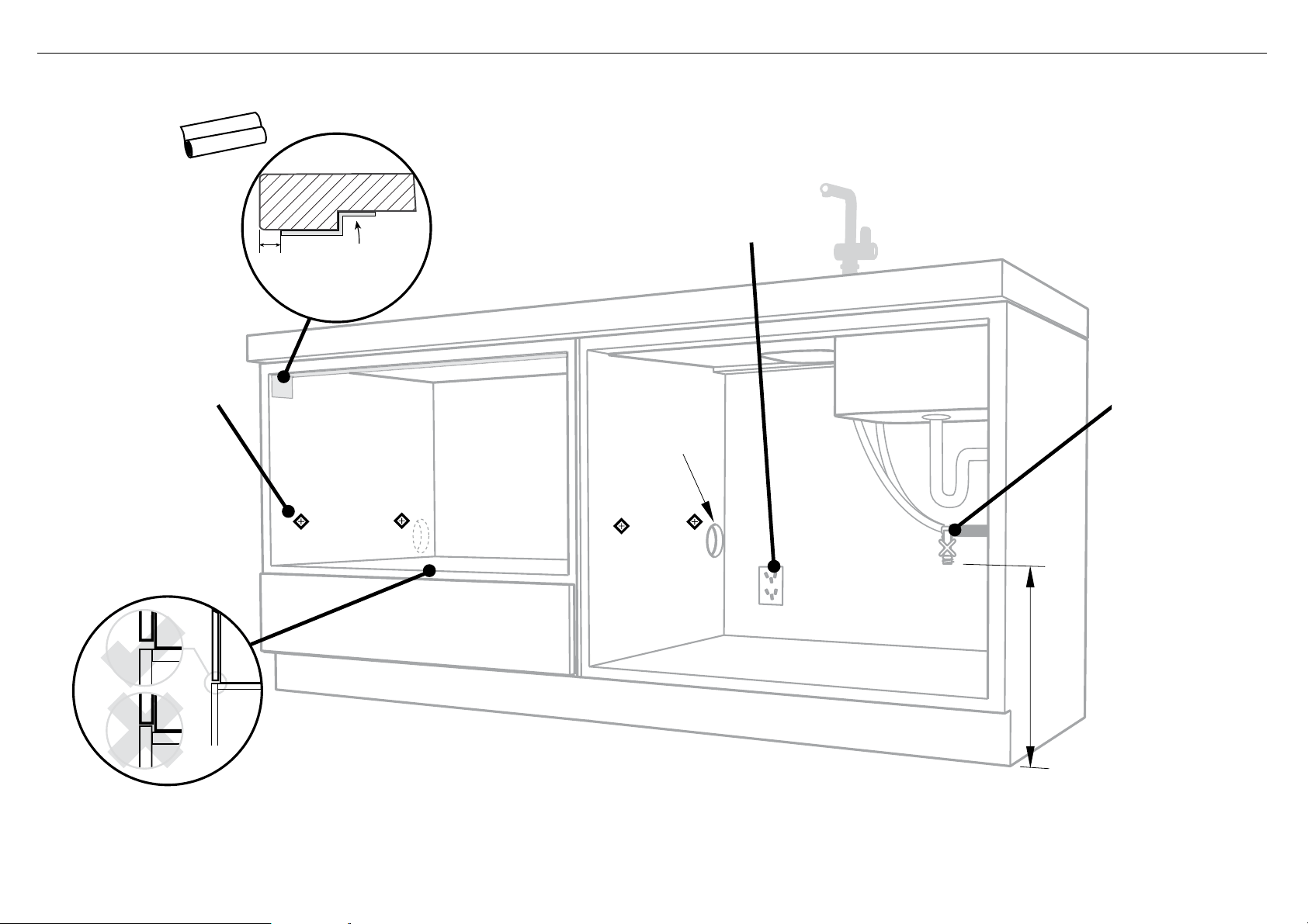
7 CAVITY PREPARATION
Water Connection
Recommended COLD
(Maximum 60°C).
3/4“ BSP (GB20) to
suit flat washer.
Kosher requirements
Drains will need to be
separated to satisfy
kosher requirements.
We suggest you confirm
acceptability with your
local rabbi in respect to
kosher installations.
Water Pressure
Water softener models
Max. 1 MPa (145 psi)
Min. 0.1 MPa (14.5 psi)
Models without water softener
Max. 1 MPa (145 psi)
Min. 0.03 MPa (4.3 psi)
IMPORTANT!
The power outlet
must be located in a
cabinet adjacent to the
dishwasher cavity.
220-240 VAC min. 9.5 A
ø 60 mm
min. 200 mm
Moisture
protection
tape must
be applied.
Services can be
located either side of
dishwasher.
These marks indicate
formed bracket screw
locations, if securing by
drawer removal.
10 mm
BENCHTOP
10
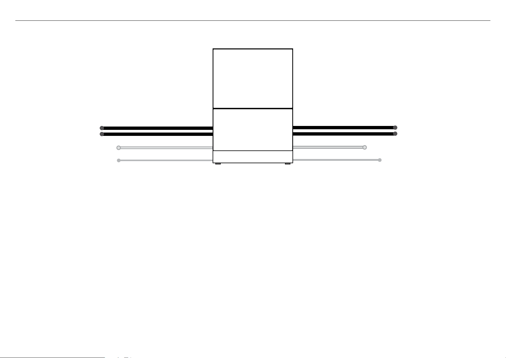
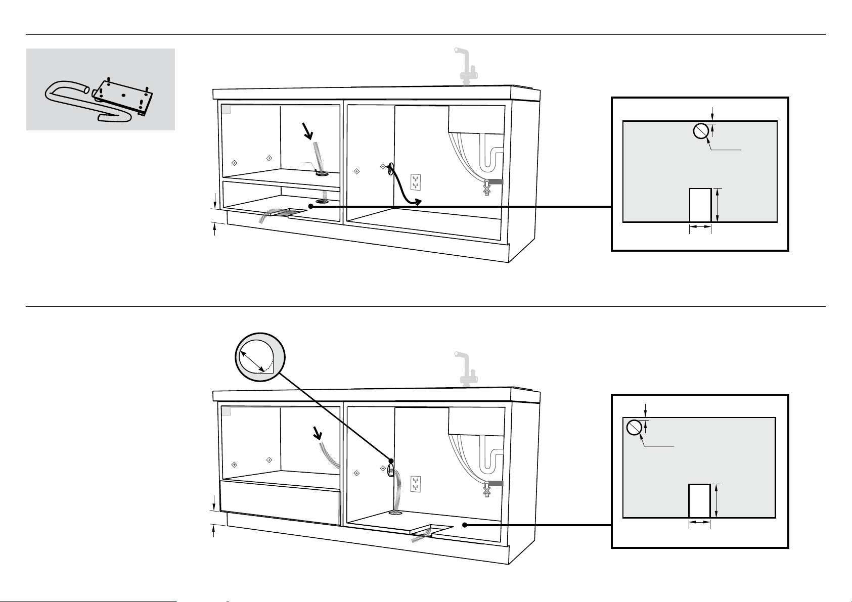
8 MAXIMUM DISTANCE OF HOSES & CORD FROM CHASSIS EDGE
LEFT HAND SIDE
Drain hoses - 2000mm Drain hoses - 1800mm
Inlet hose - 1650mm Inlet hose - 1250mm
Power cord (excl.plug) - 1650mm Power cord (excl.plug) - 1650mm
RIGHT HAND SIDE
11
(x2)
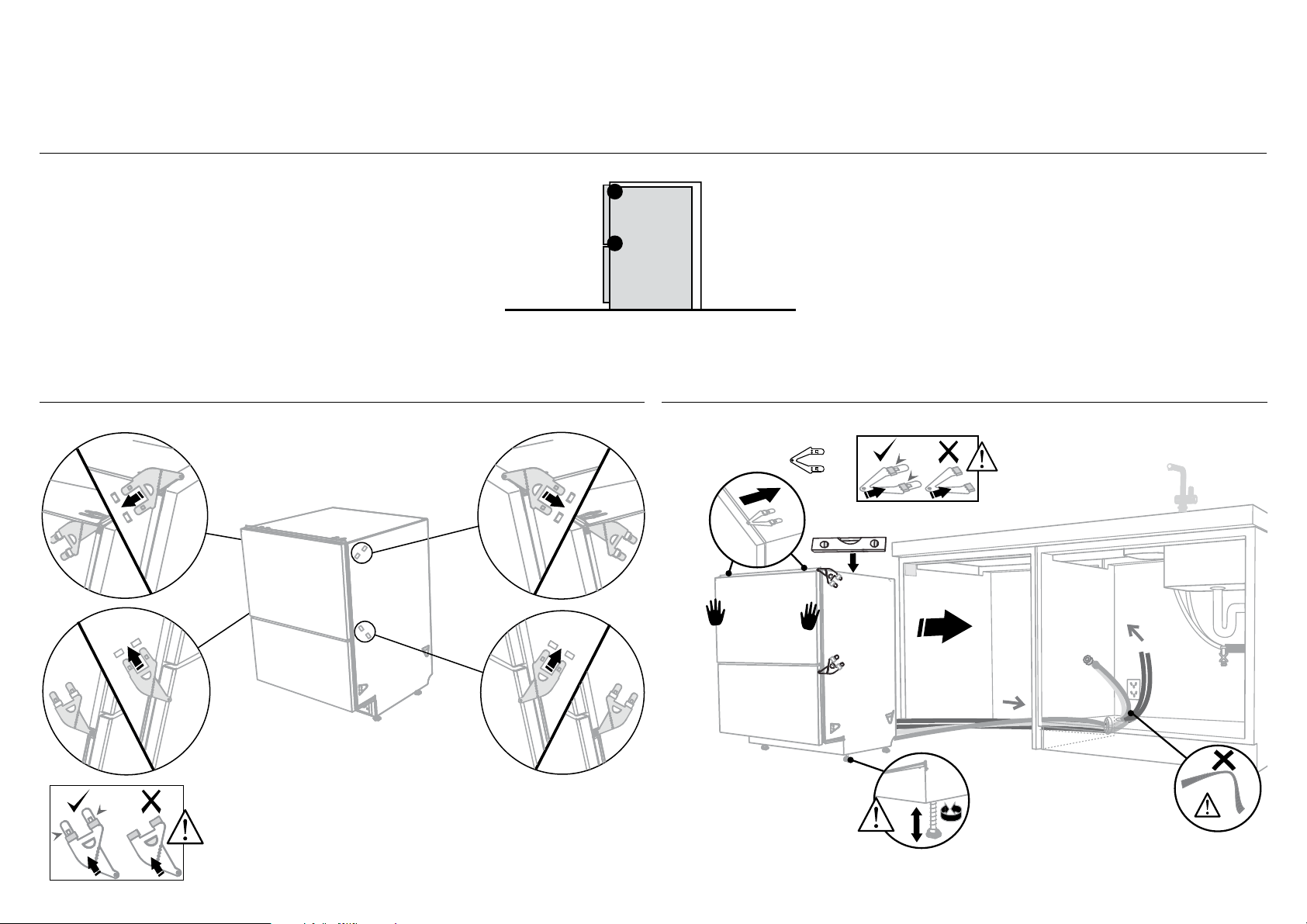
9 RECOMMENDED METHOD (A) - SECURE WITHOUT DRAWER REMOVAL (FRAMELESS CABINETRY ONLY)
NOW CHOOSE WHICH INSTALLATION METHOD (A) OR (B)
IS MORE SUITABLE FOR YOUR CABINETRY...
As you push product
in, pull through hoses
and cord, ensuring
they don’t get kinked
or twisted.
optionally attach the
two top mounting
brackets
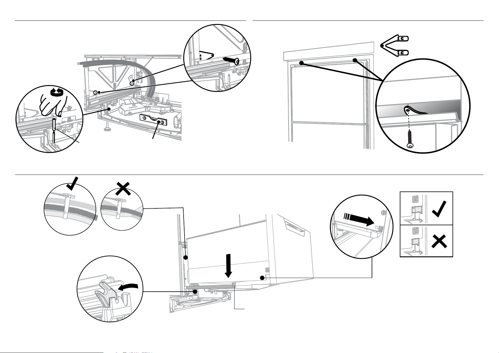
Initially level the product
A
A
A
B
B
Clip all four side mounting brackets
into their slots using a flat-bladed
screwdriver. Ensure they’re securely
fitted before sliding product into cavity.
The mounting slots are in pairs, one on
each side diagonally across the product.
A bracket must match A slot and B
bracket must match B slot.
When fitting brackets,
ensure the ends are
not pushed down into
the chassis.
When fitting brackets, ensure the
ends are not pushed down into
the chassis.
B
AB
You can raise or lower
the product by twisting
the feet. Then take
care when pushing the
product into the cavity
that you do not bend the
feet.
9-A ATTACH SIDE MOUNTING BRACKETS !0-A PULL THROUGH HOSES & PUSH INTO THE CAVITY
12
2
1
3
(x2)
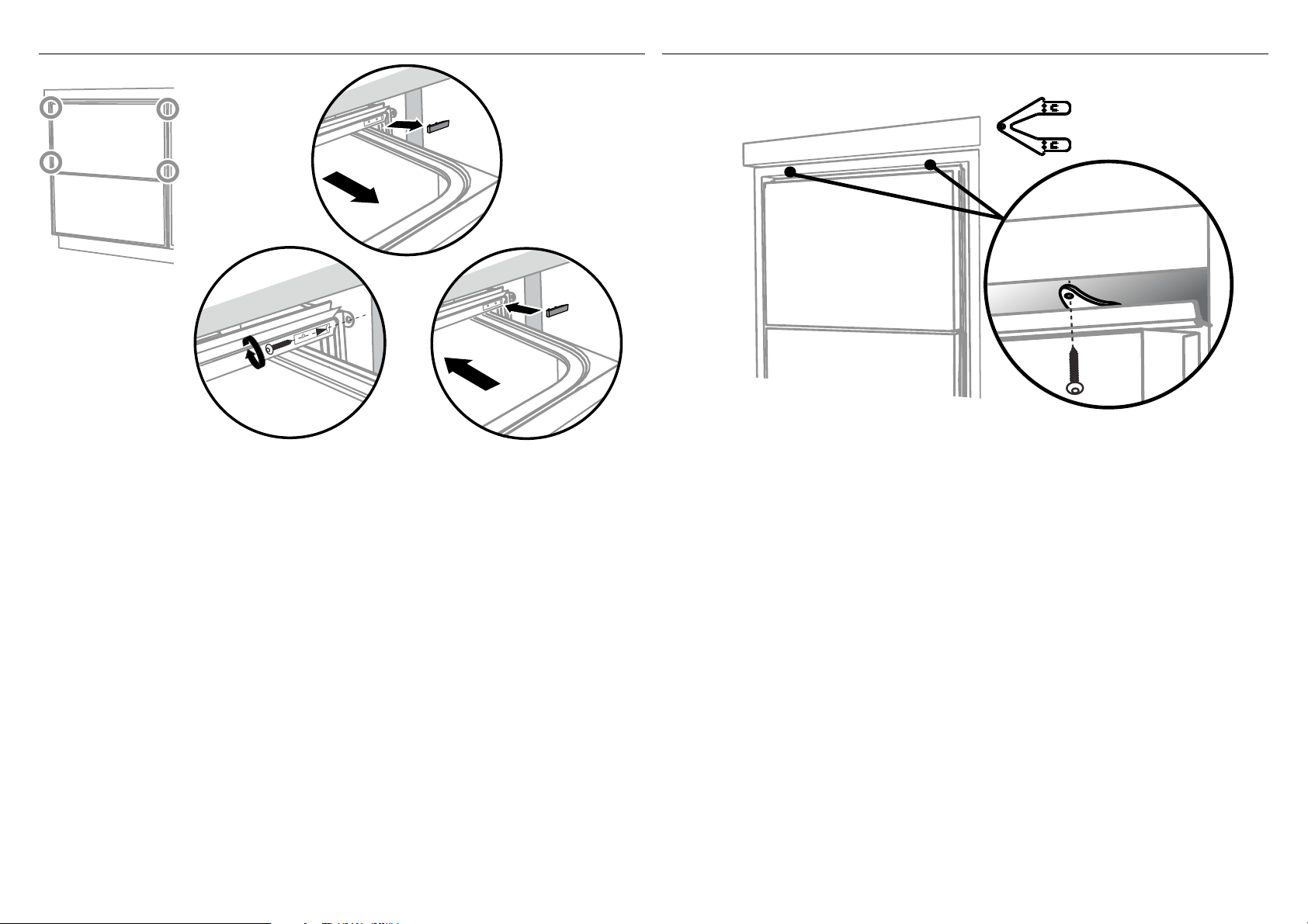
!1-A SECURE TO THE CABINETRY ON THE SIDES
!3-A AFTER SECURING, REFER TO ‘FIT THE SUPPLIED TOEKICK PANEL’ STEP
!2-A OPTIONALLY SECURE TO THE CABINETRY ABOVE
Open the
drawer halfway.
Using a flat
bladed
screwdriver,
prise the grey
rubber plug out
of the trim
moulding.
Replace the grey
rubber plug back into
the trim moulding
and ensure the trim
seal is facing forward.
Repeat for all
four brackets.
Using a small
Philips screwdriver,
screw through the
trim moulding,
securing the side
mounting bracket
to the cabinetry.
Do not damage
the rubber
trimseal.
The top mounting
brackets will only
bend upwards a
maximum of 10mm.
13
(x2)
1
2
4
4
3
3
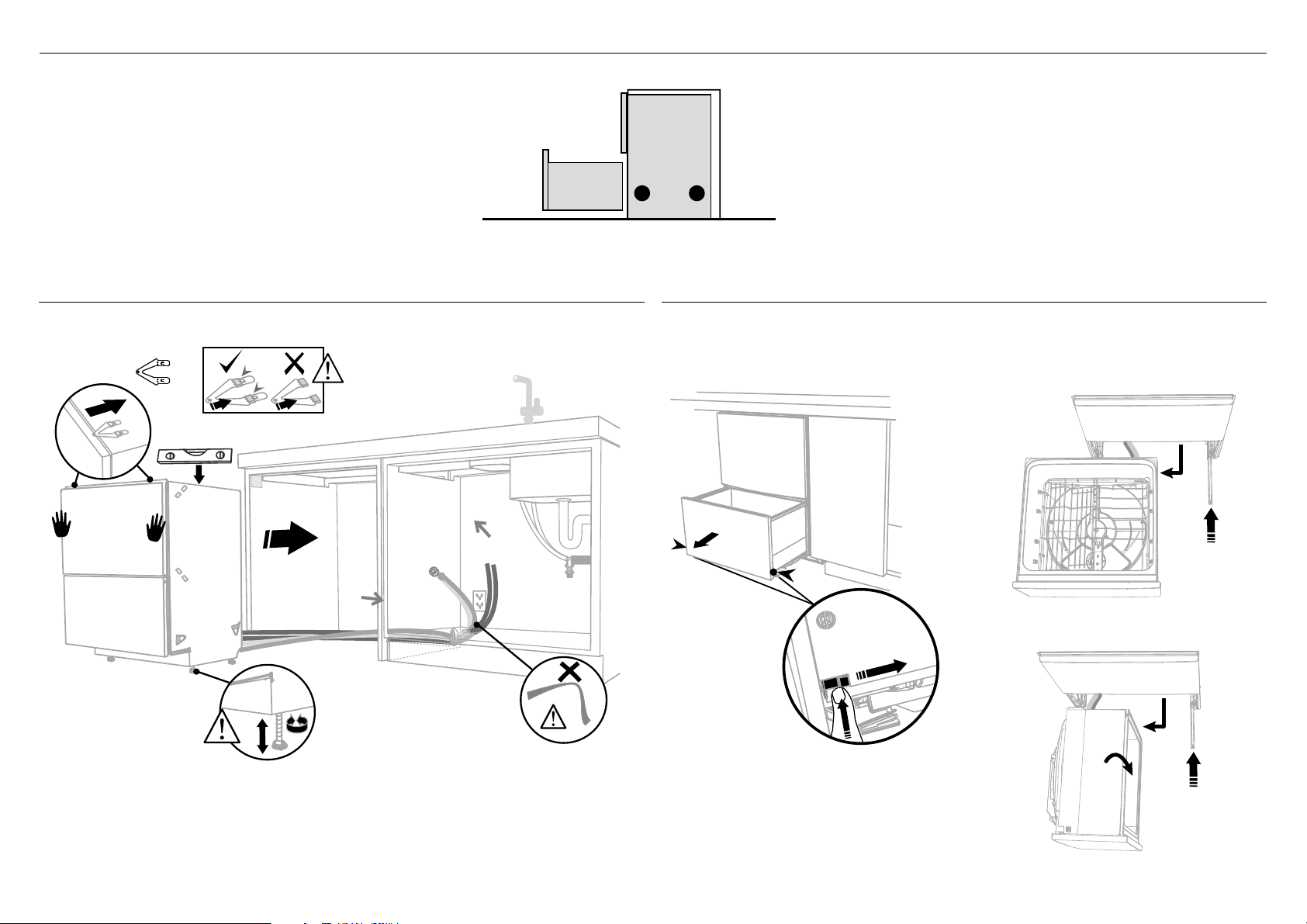
9 ALTERNATIVE METHOD (B) - SECURE BY DRAWER REMOVAL
As you push product
in, pull through hoses
and cord, ensuring
they don’t get kinked
or twisted.
optionally attach the
two top mounting
brackets
Initially level the product
You can raise or lower
the product by twisting
the feet. Then take
care when pushing the
product into the cavity
that you do not bend the
feet.
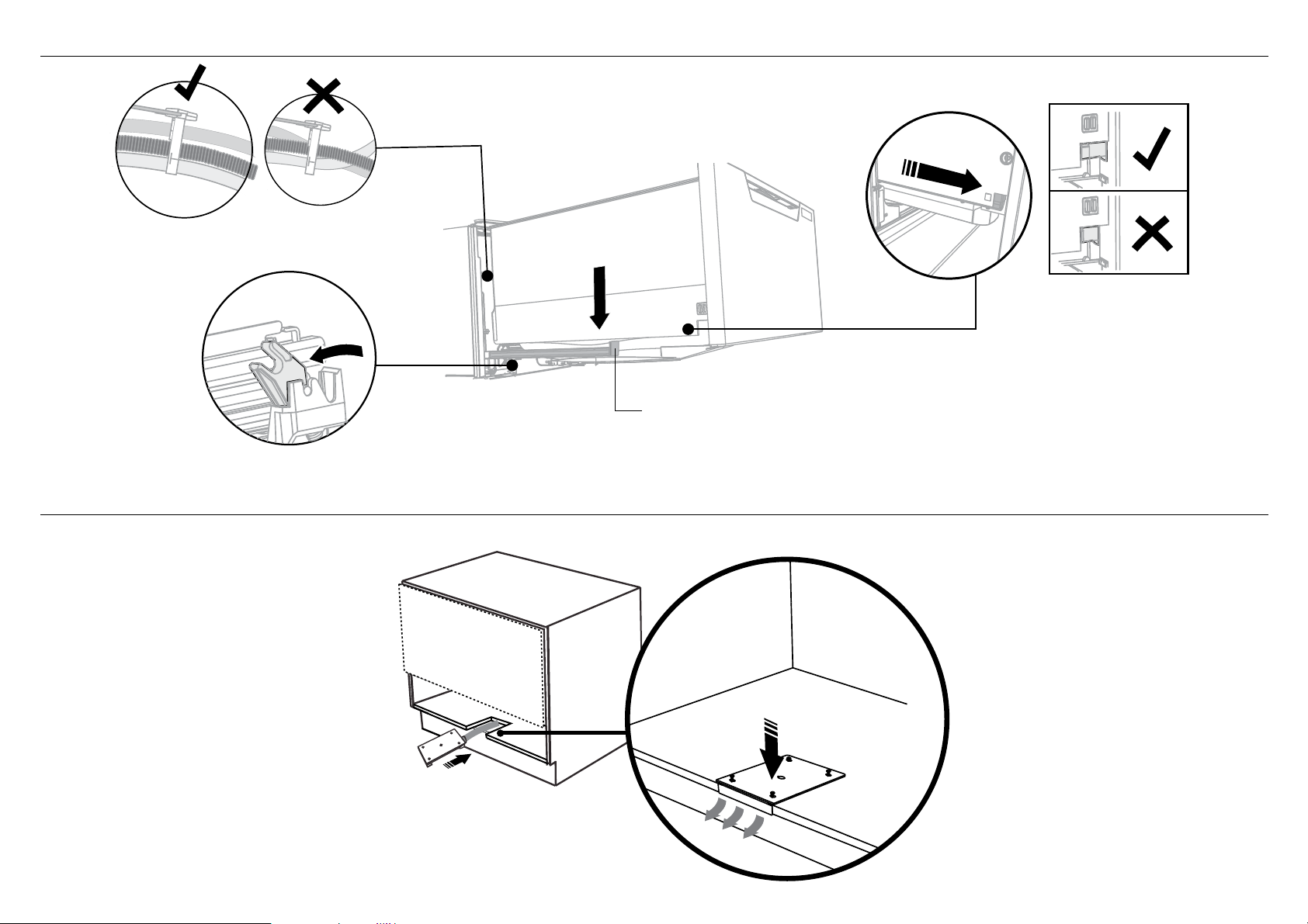
9-B PULL THROUGH HOSES & PUSH INTO THE CAVITY !0-B REMOVE THE LOWER DRAWER
To prevent kinked hoses
Either sit the drawer down on the left
hand side (recommended) or rotate the
drawer clockwise, resting it on its side after
removal.
Press the release tabs
in on either side and
push back to release
drawer from runners.
Lift drawer off runners.
Push drawer
runners back in
on either side.
Push drawer
runners back in
on either side.
Sit the drawer down
Rotate the drawer
clockwise (max. 90
o
)
and rest on side.
When fitting brackets,
ensure the ends are
not pushed down into
the chassis.
100 mm
14
x4
(x2)
1
2
3
4
!1-B SECURE TO THE CABINETRY ON THE SIDES !2-B OPTIONALLY SECURE TO THE CABINETRY ABOVE
100 mm
Secure using two pairs
of formed brackets.
Repeat on the other
side of the chassis.
For further adjustment,
using the most appropriate
length Hexagonal socket
supplied, fully extend
levelling feet up to
required distance by hand.
Ensure product is level and
aligning with cabinetry.
Hexagonal
socket
The top mounting
brackets will only
bend upwards a
maximum of 10 mm.
!3-B REFIT THE DRAWER ONTO THE RUNNERS
Before refitting the
drawer, ensure the hoses
are not twisted and the
latches at the rear of
each drawer runner are
facing forward.
Lift or rotate anti-clockwise the
drawer back onto the drawer runners
on either side.
Pull the release tabs forward on both
sides 100 mm. Ensure the tabs are fully
pulled forward and click into place.
Release tab
15
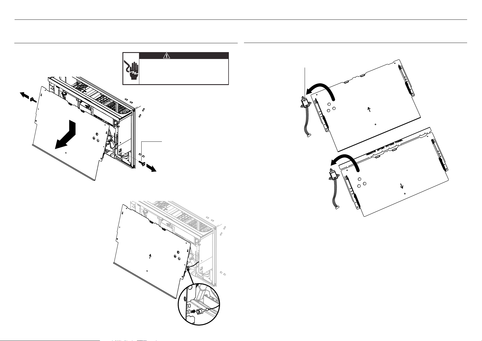
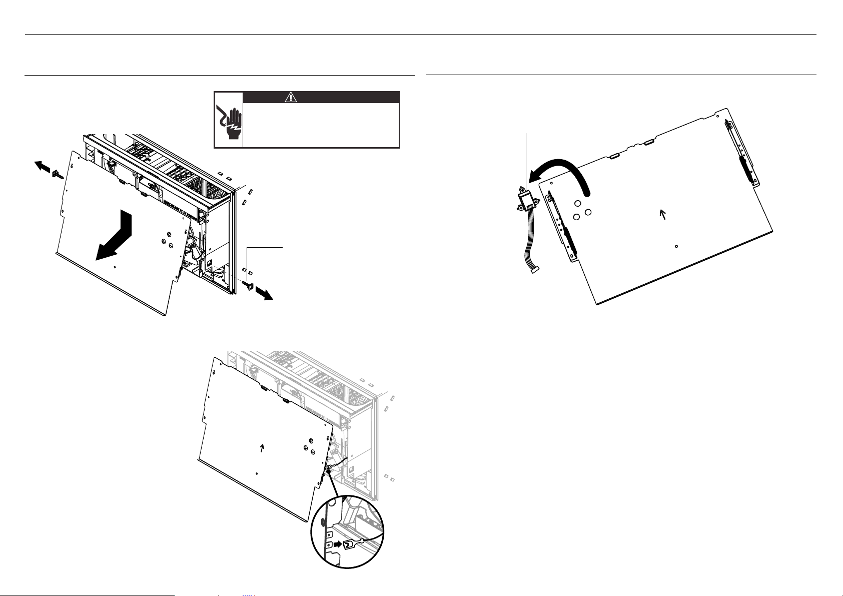
!4 INSTALLING CUSTOM FRONT DRAWER PANELS
1
1
2
Electrical Shock Hazard
WARNING!
Before continuing, ensure that the product is
disconnected from the power supply.
Failure to follow this warning may result in
electrical shock, injury or fire.
3
1
1
!4-A REMOVE BOTH PANEL BRACKETS FROM PRODUCT
Remove side pins and gently
pull off the panel bracket
slightly.
Repeat for the other drawer.
1 Disconnect the Earth Wire
from the bracket
2 Unplug the Knock-to-Pause module
from the controller.
Repeat for the other drawer.
Remove the Knock-to-Pause
module from the back of the
bracket.
Repeat for the other bracket.
Knock-to-Pause module
Side Pin
!4-B REMOVE THE KNOCK-TO-PAUSE MODULE
16
!4 INSTALLING CUSTOM FRONT DRAWER PANELS
2
3
2
16mm (x6)
4
1
1
2
16mm (x3)
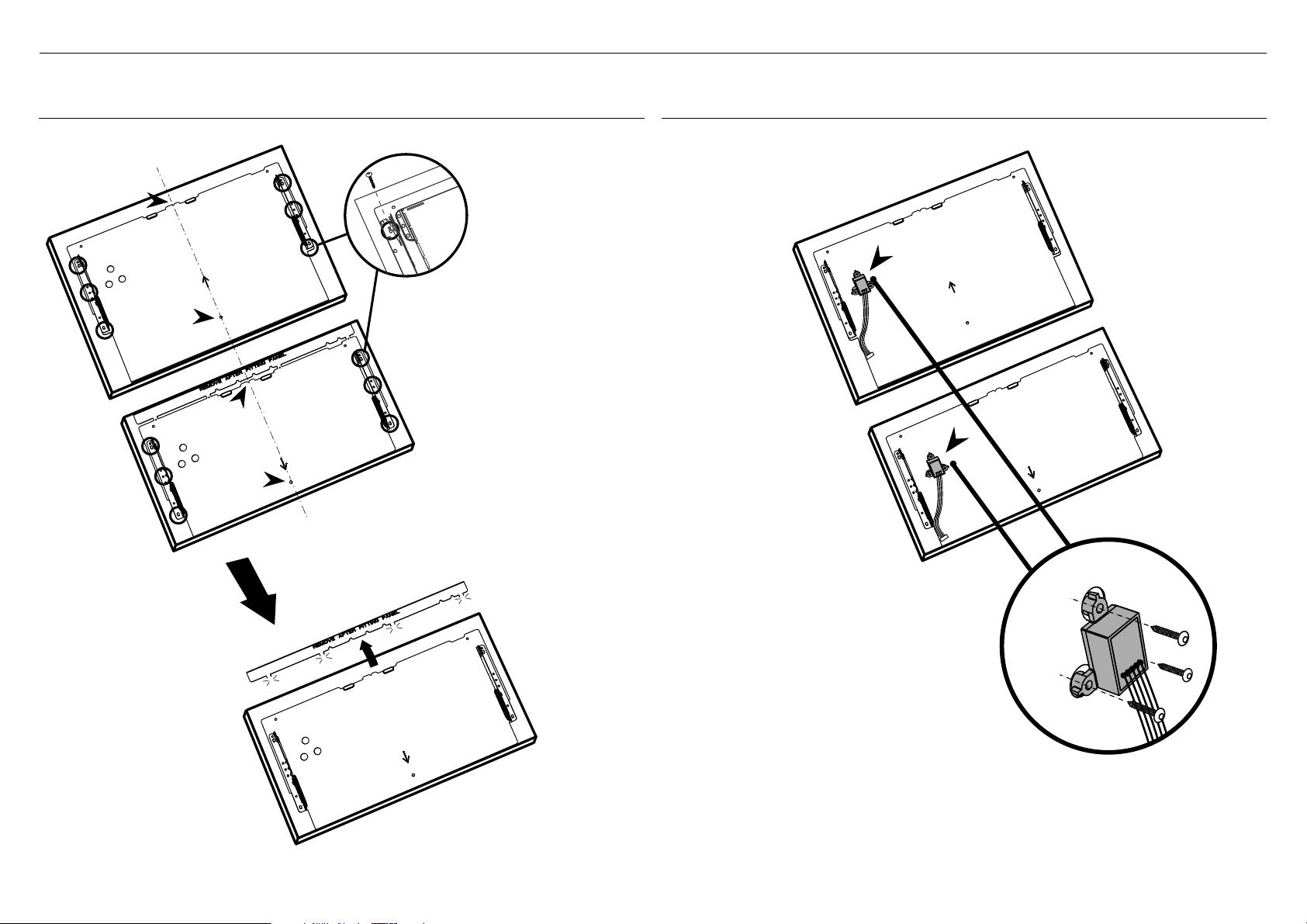
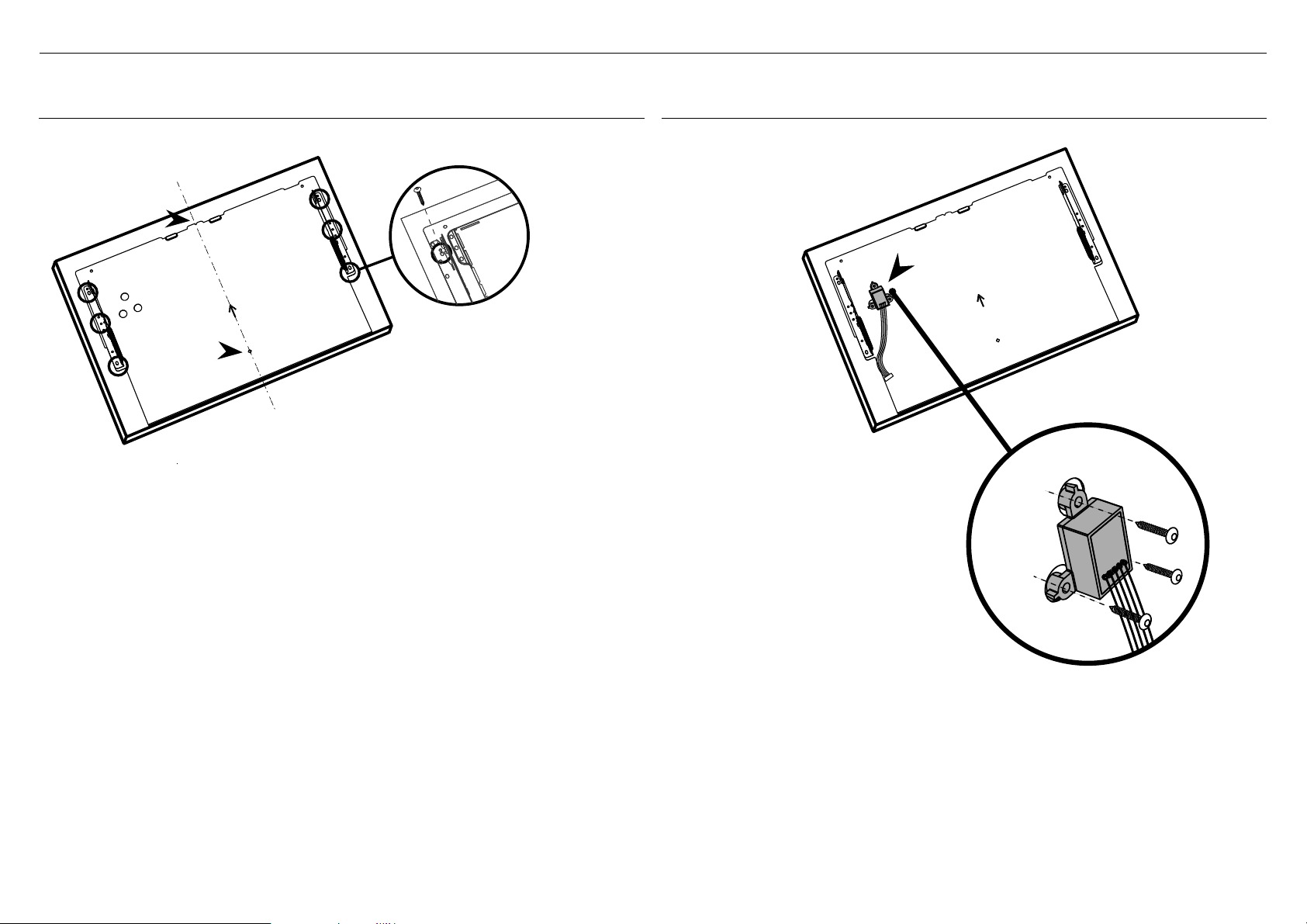
!4-C ATTACH CUSTOM PANELS TO PANEL BRACKETS
There must be at least
3 screws used each side.
IMPORTANT!
●
Ensure the Knock-To-Pause
module is orientated correctly
before attaching.
●
Ensure the module is centralized
in the holes and not in contact
with the bracket.
Attach the Knock-To-Pause
module to the back of the custom
panel through the 3 holes cut into
the panel bracket as shown.
Use all 3 screws provided.
Repeat for the other module.
Align bottom of each custom
panel with the bottom of each
bracket.
IMPORTANT!
Break off and discard the tab
at the top of the Lower Panel
Bracket.
!4-D ATTACH KNOCK-TO-PAUSE MODULES
TO CUSTOM PANELS
17
!4 INSTALLING CUSTOM FRONT DRAWER PANELS
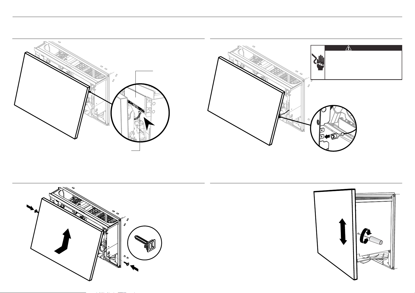
!4-E CONNECT THE KNOCK-TO-PAUSE MODULE
TO THE CONTROLLER
!4-G ATTACH CUSTOM PANELS TO PRODUCT
!4-F RECONNECT THE EARTH WIRE TO THE
PANEL BRACKET
!4-H ADJUST CUSTOM PANEL HEIGHT TO
ALIGN CABINETRY GAPS
2
2
1
Controller
Ensure the Knock-To-Pause Module
Cable is connected to the UI1 Port.
Repeat for the other drawer.
Electrical Shock Hazard
WARNING!
To earth the panel bracket, connect the earth
wire from the product to one of the tabs.
Any custom metal component (e.g. handle)
that extends past the rubber seal must be
earthed too.
Failure to follow these warnings may result
in electrical shock, injury or fire.
Reconnect the
Earth Wire to the
Panel bracket.
Repeat for the
other drawer.
+ or - 2mm
Push the Custom Panel on to
the drawer and reinsert the
side pins on each side.
Repeat for the other drawer.
With the front panels fitted, insert
an appropriately sized Philips
screwdriver into the hole above the
side pin and rotate the panels up or
down to align the gaps
in your cabinetry.
Repeat on the other side if necessary.
Each panel has a maximum travel of
2mm up or down.
IMPORTANT!
Ensure that you maintain a minimum
of 8mm ventilation gap between the
upper and lower panels.
Side Pin
18
!5 FITTING A CUSTOM TOEKICK PANEL
PROFILE A
PROFILE B
9
Custom Toekick Panel
Toekick panel cutting template
Custom toekick panel
Toekick mounting bracket
cutting template
Toekick mounting
bracket
Align panel
with the ribs
Toekick Depth
For a Toekick Depth 40mm
Depth is measured from FRONT of door
panel (assuming thickness ~18mm) to front
face of custom toekick panel
For a Toekick Depth 40-88mm
For a Toekick Depth 88-100mm
Toekick panel cutting template:
PROFILE A
Toekick panel cutting template:
PROFILE B
NO CUTOUT
40mm
40-88
mm
88-100mm
CUSTOM TOEKICK PANEL
CUSTOM TOEKICK PANEL
CUSTOM TOEKICK PANEL
If you require a cutout in your custom
toekick panel, choose the most
appropriate cutout profile (A or B)
depending on the final depth of your
toekick panel.
After marking the panel, carefully cut or
router out the desired profile. Use the
template as a cutting guide.
Place the Toekick panel cutting template onto
your toekick panel. Ensure they are centered
and the template rests on the top surface of
the panel.
Secure template to panel either by clamping
or using the supplied mounting screws.
1
4
4
5
6
1
2
2
3
3
IMPORTANT!
Do not overtighten screw.
IMPORTANT!
Ensure all bare edges are sealed appropriately.
Slide the toekick onto the mounting rails
either side and screw the toekick onto
the bottom of tub on either side.
Place the Toekick mounting bracket onto your
toekick panel. Ensure they are centered and
the horizontal ribs at the top of the template
aligns with the top surface of the panel.
Secure template to panel using the supplied
toekick mounting screws.
5
6
7
7
19
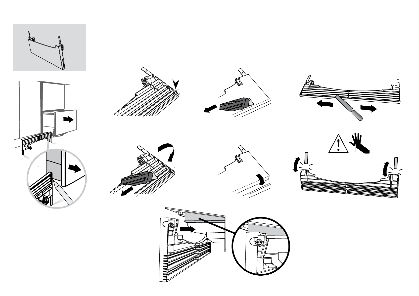
!6 FIT THE SUPPLIED PREFINISHED TOEKICK PANEL (IF PREFERRED)
1
2
3
4
19
19
5
6
8
9
7
IMPORTANT!
Do not overtighten screw.
Slide the toekick onto
the mounting rails
either side and screw
the toekick onto the
bottom of tub on
either side.
Where the toekick
meets the bottom
of the tub is the
cut-off point
Mark this point
on the toekick
with a pencil
Lay the toekick face down on
a chopping board or similiar
Score along with a knife Gently snap off the excess Snap off the two end tabs
Turn the toekick over and
score along the same line
Smooth the edge with a file.
Be careful of sharp edges.
Prefinished Toekick Panel
1
2
3
5
7
8
6
4
9
20
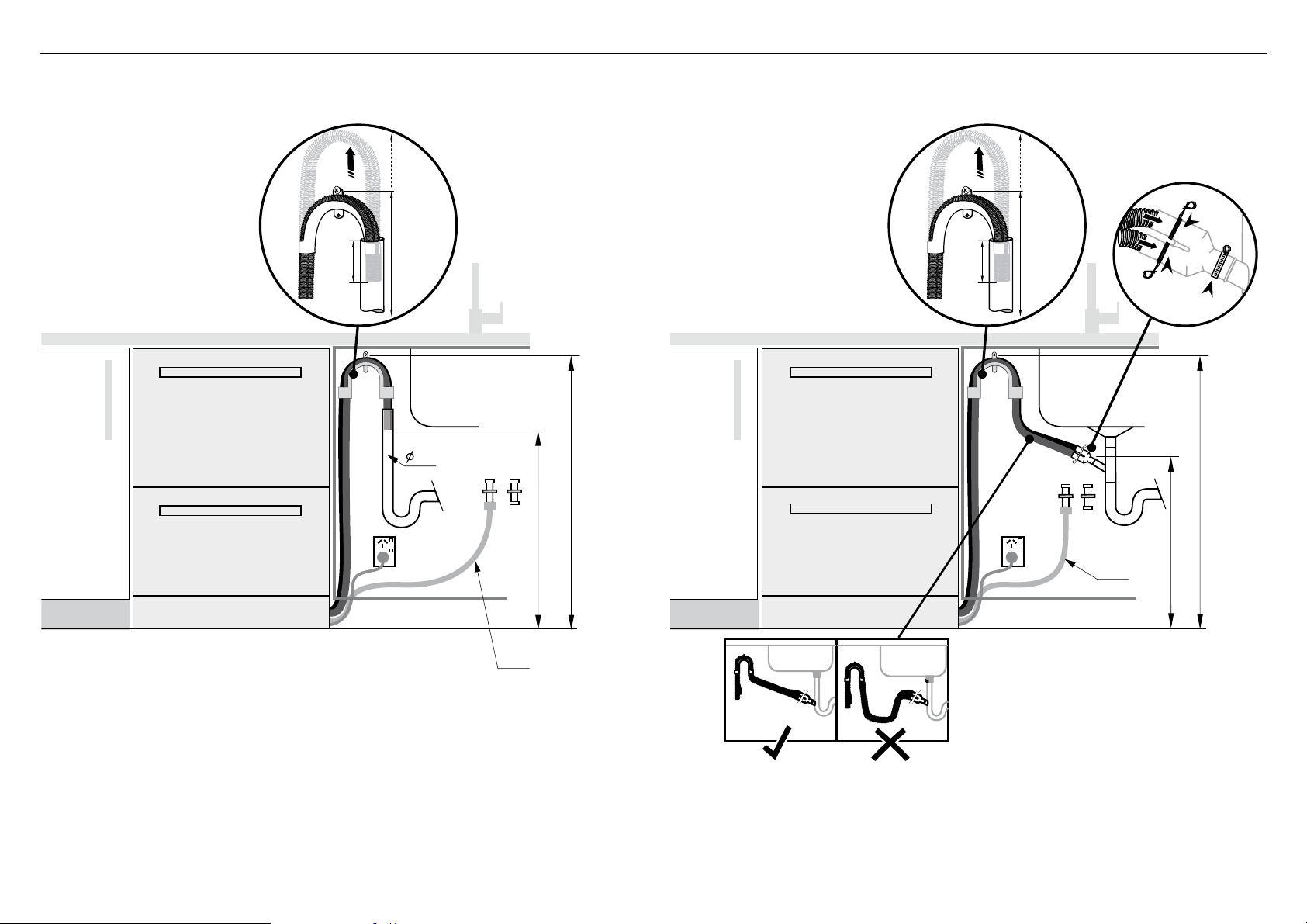
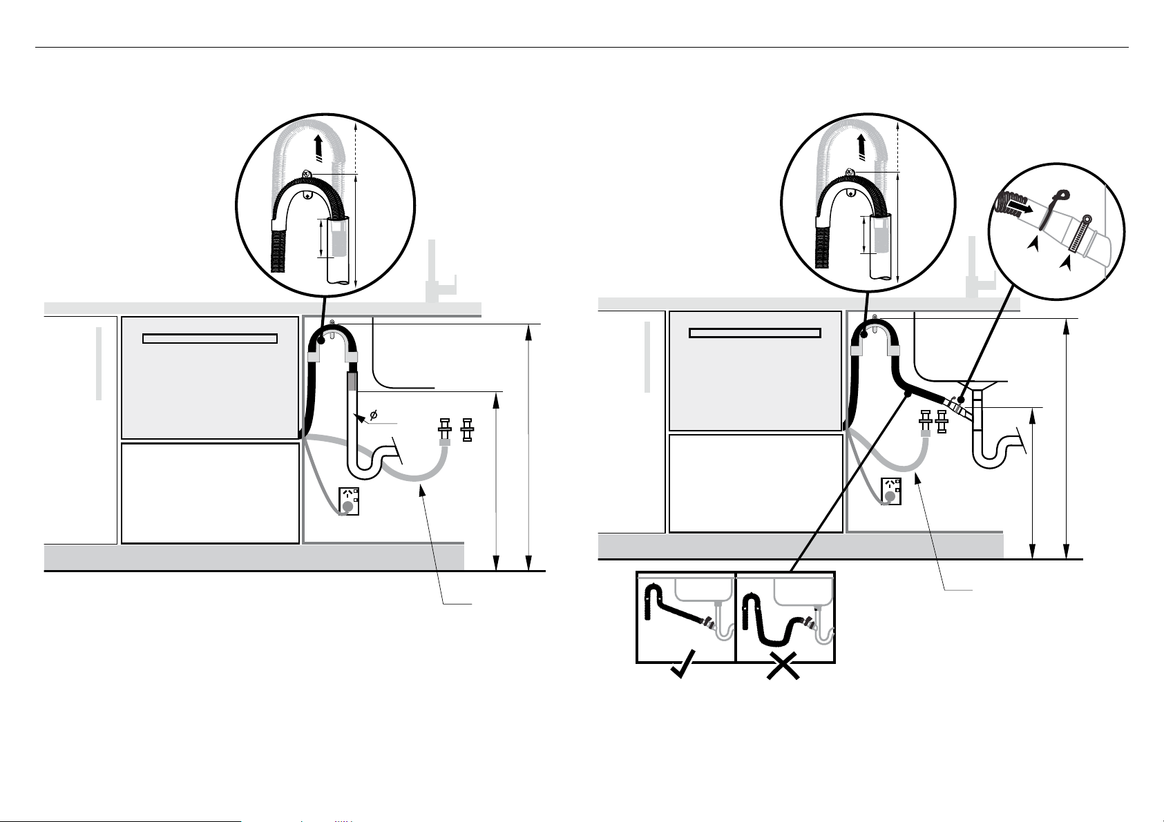
!7 THERE ARE TWO DIFFERENT PLUMBING AND DRAINAGE OPTIONS. CHOOSE WHICH IS MORE SUITABLE.
1
2
1
2
3
If space is limited
for fixing, push
hose through drain
hose support
to required height
If space is limited
for fixing, push
hose through drain
hose support
to required height
Dishwasher using drain hose joiner onto sink trap/waste tee
min. radius
200 mm
750 - 882.5 mm
750 - 882.5 mm
min. 500 mm
min. 500 mm
min. radius
200 mm
step 16
step 16
Supplied drain
hose joiner to suit
19 mm waste tee
Ensure drain hose is routed
straight to joiner. Remove excess
drain hose material if necessary.
Do not shorten the inlet hose.
Dishwasher and Ø 38 mm Standpipe
IMPORTANT!
Do not connect the drain hoses
to a Waste Disposal Unit, as this
type of connection may lead to a
blockage in the drain hoses.
750-882.5 mm
750-882.5 mm
38mm
max.
120mm
max.
120mm
21
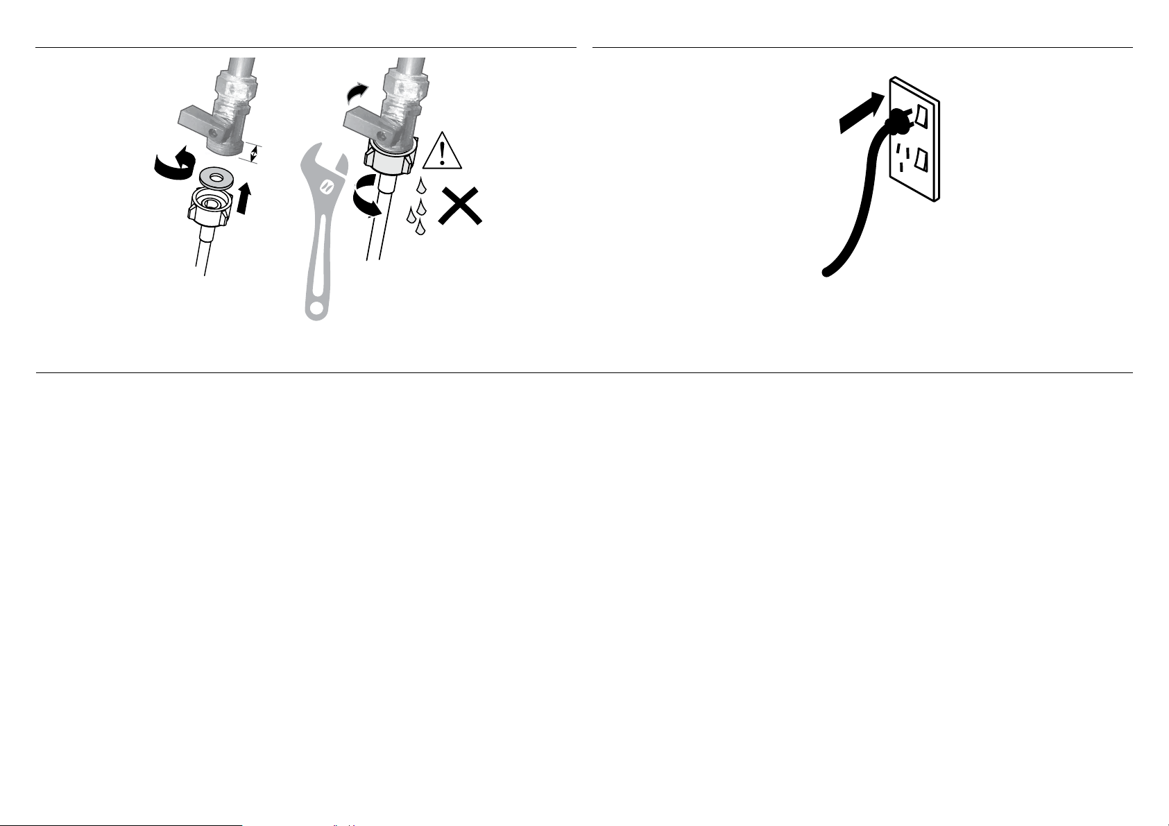
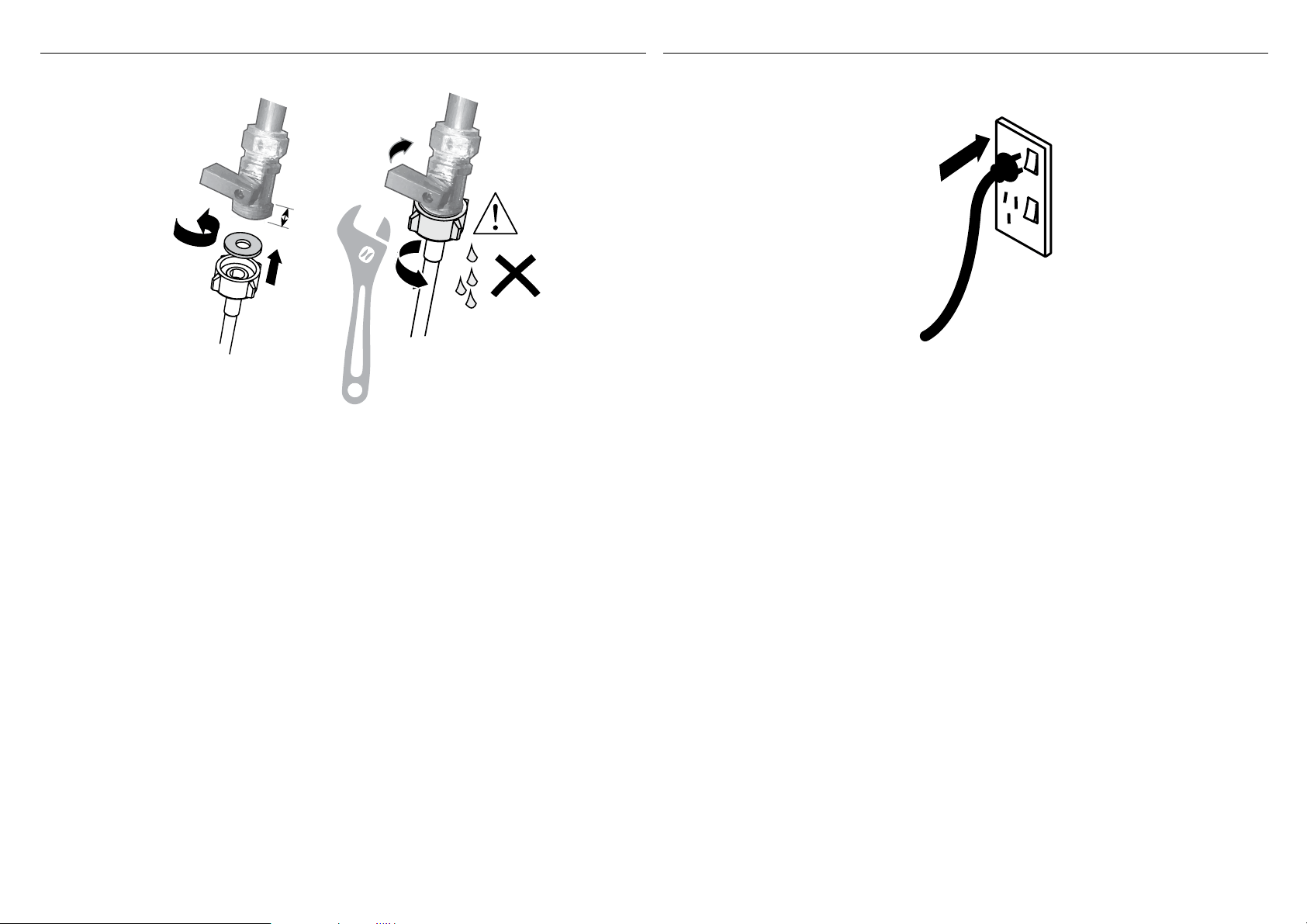
Ensure the supplied
rubber washer is
fitted inside the
coupling.
Tighten coupling with spanner.
180
o
No leaks!
1
2
min.
10mm
3/4” BSP connector
!6 CONNECT INLET HOSE TO COLD WATER !7 PLUG PRODUCT IN
!8 TROUBLESHOOTING
●
Excessive water remaining above the filter plate, after the rinse cycle. (This is displayed as an A3 fault. See user guide ‘How to attend to a fault’)
Check for a kinked drain hose, blocked or incorrectly drilled out waste connection, highloop not properly installed, drain hose not routed correctly or spray arms not in place.
●
No water supply. (This is displayed as an A1 fault. See user guide ‘How to attend to a fault’)
Check water is connected and turned on.
●
The dishwasher is beeping continuously
There is a fault. See section ‘How to attend to a fault’ in the User guide for further information and instructions.
●
No program indicator lights up when the drawer is opened
Ensure power is connected and is switched on. If it is and still no indicator lights up, see the ‘Preference options’ section of the ‘Quick start guide’. An option called ‘Open drawer auto power-on’
may need to be turned on.
●
Water around water supply and drainage connections
Check connections, existing plumbing and hoses for leaks. Check rubber washer and hose clamp are correctly fitted.
●
If product is tipping
Ensure the product is secured to the cabinetry.
●
If front panels are misaligned
Check and relevel product. Unscrew the product from the cabinetry. Adjust the feet to level the product, then re-secure to the cabinetry. Check the cabinetry is square.
●
Drawer doesn’t close properly
Ensure nothing is obstructing the drawer from closing properly eg hoses or drawer latches.
●
If a problem occurs, consult the ‘Troubleshooting’ section of the User guide.
●
If after checking these points you still need assistance, please refer to the Service & Warranty book for warranty details and your nearest Authorised Service Centre, or contact us through our
website, listed below.
22
!9 FINAL CHECKLIST
TO BE COMPLETED BY THE INSTALLER
Complete and keep for safe reference:
Model
Serial No.
Purchase Date
Purchaser
Dealer Address
Installer’s Name
Installer’s Signature
Installation Company
Installation Date
Check all parts are installed.
Ensure that all panels and parts thereof are secure and final electrical tests have been
conducted in accordance with local electrical regulations.
Ensure product is level, securely fastened to the cabinetry and opens and closes freely.
The drawers must be free to fully close with no resistance from the cabinetry.
Ensure inlet hose to water supply has supplied rubber washer fitted, and that it’s
tightened a further half turn after seal contact.
Ensure any knockouts or plugs in drain connection have been drilled out and drain
connection has been made.
The drain hose joiner must not support the weight of excess hose material. Keep drain
hose as fully extended as possible to prevent sagging. Any excess length of drain hose
should be kept on the dishwasher side of the highloop.
If connecting the drain hose to the sink trap, ensure the Highloop is a minimum 150mm
higher than the drain hose joiner.
Ensure any packaging or tape securing the racks is removed from the drawers.
Water softener models only: adjust the water softener setting from the default setting to
suit the water hardness of the area.
See the Quick start guide and section ‘Water softener’ in the User guide.
Turn on the power and water supplies, then open the drawers. You should hear a
beep and see a program indicator light up on the control panel.
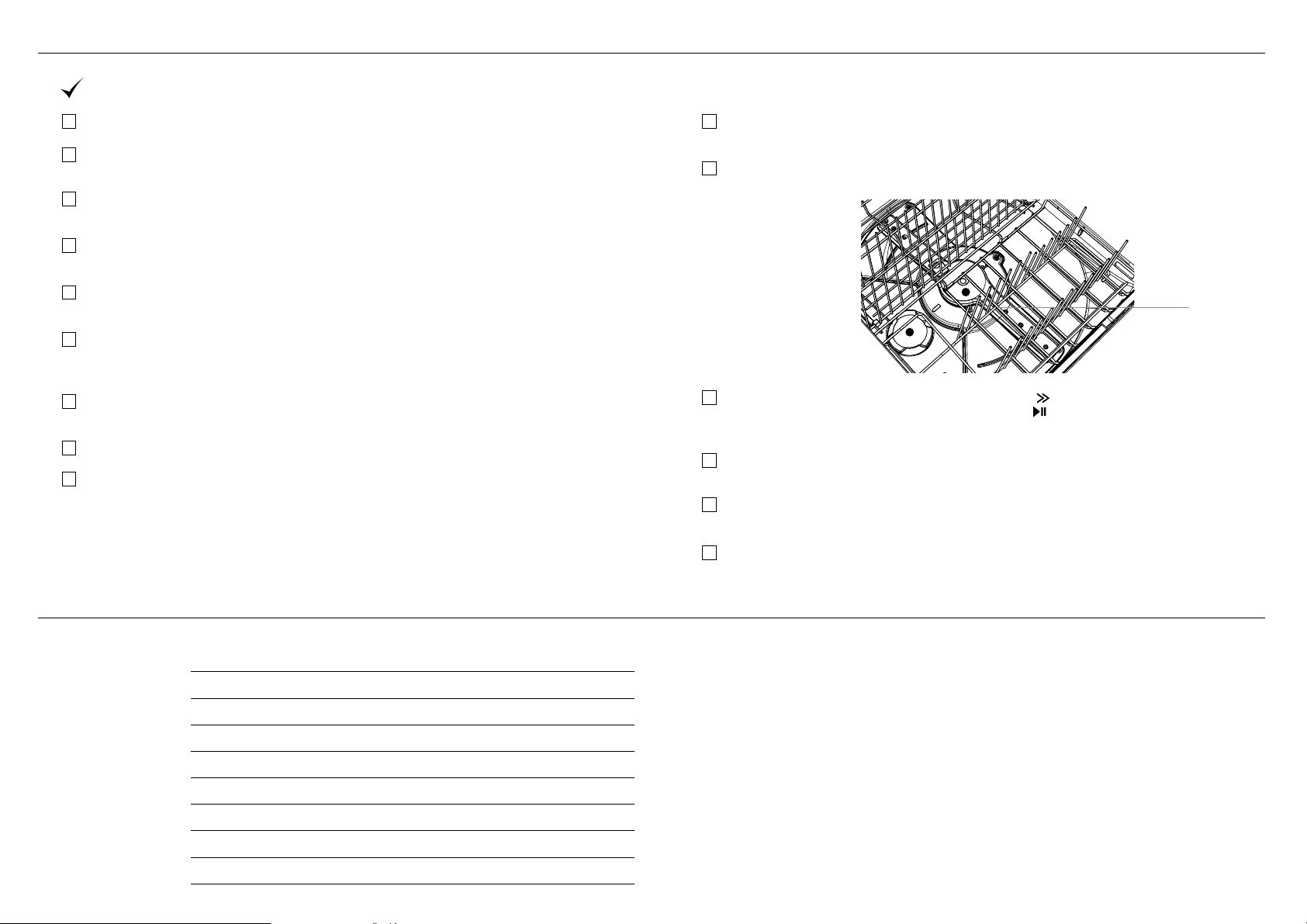
Check the spray arms are in place, mounted correctly and free to rotate, by
physically rotating by hand.
Add three cups of water into the drawer. Press
until the indicator of the ‘Rinse’
program lights up. Close the drawer and press to start the program.
Repeat for the other drawer.
When the test cycle is in process check the knock sensor is working by knocking
twice on the door to pause the wash program.
After the Rinse program has finished, ensure the dishwasher has run and drained
correctly.
Check the water supply has correctly shut off and drainage connection for leakage.
Spray arm
Copyright © Fisher & Paykel Appliances 2017. All rights reserved.
The product specifications in this booklet apply to the specific products
and models described at the date of issue. Under our policy of continuous
product improvement, these specifications may change at any time. You
should therefore check with your Dealer to ensure this booklet correctly
describes the product currently available.
FISHERPAYKEL.COM

5918 A 08.17
INSTALLATION GUIDE
NZ AU GB IE
DD60SI, DD60STI, DD60SLI, DD60SHI
& DD60SHTI models
SINGLE DISHDRAWER
TM
DISHWASHER

1
2
1 SAFETY AND WARNINGS
WARNING!
Electrical shock hazard
Before installing the dishwasher, remove the
house fuse or open the circuit breaker.
This appliance must be earthed. In the event
of a malfunction or breakdown, earthing will
reduce the risk of electric shock by providing
a path of least resistance for electric current.
This appliance is equipped with a cord having
an equipment-earthing conductor and an
earthing plug. The plug must be plugged into
an appropriate outlet that is installed and
earthed in accordance with all local codes and
ordinances.
WARNING- Improper connection of the
equipment-earthing conductor can result in a
risk of electric shock. Check with a qualified
electrician or service representative if you are
in doubt as to whether the appliance is properly
earthed.
Do not modify the power supply plug provided
with the appliance - if it will not fit the outlet,
have a proper outlet installed by a qualified
electrician. Do not use an extension cord,
adapter plug or multiple outlet box.
Failure to follow this advice may result in
electrical shock or death.
WARNING!
Electrical Shock Hazard
WARNING: To reduce the risk of electrical
shock, fire, or injury to persons, the installer
must ensure that the dishwasher is completely
enclosed at the time of installation.
Before fitting the front panels and connecting
the integrated badges (where present), the
installer must ensure that the dishwasher is
disconnected from the power supply.
After installing the front panels, the installer
must ensure that the following components
are electrically earthed: the panel bracket, the
integrated badge (where present) and any
custom metal component (e.g. handle) that
extends past the rubber seal.
Failure to follow these warnings may result in
electrical shock, injury or fire.
WARNING!
Cut Hazard
Take care - panel edges are sharp.
Failure to use caution could result in injury or
cuts.
! !
!
Fitting integrated front panels requires access to
electrical service areas.
This work must be performed and certified by a
qualified electrical service technician.

3
1 SAFETY AND WARNINGS
IMPORTANT SAFETY INSTRUCTIONS
●
Installation of this dishwasher requires basic
mechanical and electrical skills.
●
Be sure to leave these Instructions with the Customer.
●
Installation must comply with your local building and
electricity regulations.
●
At the completion of the dishwasher installation, the
Installer must perform the Final Checklist.
●
Remove all packaging materials supplied with the
dishwasher.
●
This dishwasher is manufactured for indoor use only.
●
Ensure all water connections are turned OFF. It is the
responsibility of the plumber and electrician to ensure
that each installation complies with all Codes and
Regulations.
●
The dishwasher MUST be installed to allow for future
removal from the enclosure if service is required.
●
The switched power outlet must be outside the
dishwasher cavity, so that it is accessible after
installation.
●
Care should be taken when the appliance is installed
or removed to reduce the likelihood of damage to the
power supply cord and hoses.
●
If the dishwasher is to be relocated from one
installation to another it must be kept upright to avoid
damage from water spillage.
●
Make sure only new hoses are used for connection
(supplied with the dishwasher). Old hoses should not
be reused.
●
Failure to install the dishwasher correctly could
invalidate any warranty or liability claims.
IMPORTANT SAFETY INSTRUCTIONS
●
Ensure the product is not plugged in when fitting
custom panels.
●
Installation of custom panels requires basic mechanical
and electrical skills.
●
Installation must comply with your local building and
electricity regulations.
●
Failure to install the custom panels correctly could
invalidate any warranty or liability claims.
IMPORTANT!
SAVE THESE INSTRUCTIONS
The models shown in this installation guide may not be available in all markets and are subject to change at any time. For current details about model and specification availability in your country, please go to our
website www.fisherpaykel.com or contact your local Fisher & Paykel dealer.
4
2 PARTS SUPPLIED
If the Drain hose supplied is not long enough to reach your services, you must use a Drain Hose Extension Kit P/N 525798 which will extend the drain hose by 3.6 m.
The kit is available from the nearest Fisher & Paykel Authorised Service Centre or our local website listed at the end of this document.
Clamp (1)
(for securing
Drain hose joiner)
Wire clip (1)
(for securing
Drain hose joiner)
Phillips
16 mm
screws (7)
38 mm
bottom fixing
screws & metal
washers (2)
Drain hose
support (1)
Moisture protection
tape (1)
(to prevent moisture
damage to cabinetry)
Cavity Bracket Kit (1)
(supplied with Tall
Height Models only)
Drain hose
joiner (1)
Top
mounting
brackets (2)
OPTIONAL
Rubber washer
for inlet hose (1)
(comes already
fitted)
Side mounting
bracket kit
(A and B) (2)
OPTIONAL
External Venting kit (1)
(Excludes DD60SLI9 models)
Panel mounting
screws (6)
Panel bracket (1)
& Knock-to-Pause Module (1)
(shipped fixed to product)
5
3 PRODUCT DIMENSIONS
C
B
H
FG
A
D
I
E
PLAN
PROFILEFRONT
DD60SLI
DD60SI
DD60SHI
DD60STI
DD60SHTI
DD60STI
DD60SHTI
PRODUCT DIMENSIONS MM MM MM MM
A
Overall height of product
1
410 410 454 478
2
B
Overall width of product 599 599 599 599
C
Overall depth of product
3
571 571 571 571
D
Depth of chassis (to back of front drawer panel) 553 553 553 553
E
Depth of drawer front panel 16-20 16-20 16-20 16-20
F
Height of drawer front panel min. 408 min. 398
4
min. 452
5
min. 476
5
G
Height of chassis
1
410 410 454 454
H
Ventilation gap below drawer front panel min. 8 min. 2 min. 2 min. 2
I
Maximum extension of drawer
3
545 545 545 545
1
includes 2mm high bracket slots
2
includes fitted cavity bracket
3
assuming a front panel thickness of 18mm
4
recommended for a 2mm ventilation gap below panel, if cavity height is 412mm
5
recommended for a 2mm ventilation gap below panel
STANDARD
HEIGHT
STANDARD
HEIGHT
TALL
HEIGHT
(Installed in a
18” (456mm)
high cavity)
TALL
HEIGHT
(Installed in a
18 7/8” (480mm)
high cavity)
6
4 CABINETRY DIMENSIONS
DD60SI
DD60SHI
DD60SLI
DD60STI
DD60SHTI
DD60STI
DD60SHTI
CABINETRY DIMENSIONS MM MM MM
J
Inside height of cavity min. 412 456 480
K
Inside width of cavity 600 600 600
L
Inside depth of cavity min. 560 min. 560 min. 560
()
min.
412mm
456mm
480mm
J
J
J
Dishwasher Dishwasher
Dishwasher
DD60SI, DD60SLI, DD60SHI
STANDARD HEIGHT INTEGRATED MODEL
DD60STI, DD60SHTI
TALL HEIGHT INTEGRATED MODEL
(Installed in a 456mm high cavity)
D60STI, DD60SHTI
TALL HEIGHT INTEGRATED MODEL
(Installed in a 480mm high cavity)
Compact
Oven
Full Size
Oven
Cavity height options allow you to match dishwasher with your cabinetry or companion products
STANDARD
HEIGHT
TALL
HEIGHT
(Installed in a
456mm high
cavity)
TALL
HEIGHT
(Installed in a
480mm high
cavity)
Q
P
Bracket slots
PLAN
Minimum clearances from adjacent cabinetry
min. 13 mm
clearance
from a corner
cupboard
min. 2 mm
clearance
to adjacent
cupboard door
Cavity Bracket (480mm cavity height)
Custom Filler Panel (other heights)
PROFILE
TALL HEIGHT MODELS ONLY
If your cavity height leaves a visible gap
under your countertop when you open
the drawer:
Fit the supplied cavity bracket (or
a custom cavity filler panel) before
installation in order to conceal any
gap at the top of the cavity left after
installation.
J
K
L
7
5 CUSTOM DRAWER PANEL CALCULATIONS
The following calculations assume the top of the upper panel is
aligned with the top of the adjacent cabinetry.
WIDTH OF THE PANEL
Measure A (the width between adjacent door/drawer fronts)
and write it in the first box below, then complete the equation.
HEIGHT OF THE PANEL
min. 2mm
Ventilation Gap
(min. 2mm)
with External Venting
Kit installed
Ventilation Gap (min. 2mm)
with External Venting Kit installed
min. 2mm
min. 2mm
min. 2mm
WIDTH OF PANEL
HEIGHT OF
PANEL
PANEL
B
A
A
B
Clearance to adjacent
cabinet front
(min. 2mm)
(min. 2mm)
(596 - 615mm)
Ventilation Gap
WIDTH OF PANEL
HEIGHT OF PANEL
Note: when the top of the dishwasher
has to be lower than the adjacent
cabinetry, the top of the panel can
extend above the chassis where required,
however a min. 2mm gap to
the benchtop must be maintained.
DD*SLI9 models only:
This model is installed conventionally without an External Venting Kit.
Therefore, the Ventilation Gap below the product in all calculations is min. 8mm.
- 2x =
=-
FRONT PANEL MATERIAL SPECIFICATIONS
●
16 - 20mm panel thickness
●
Adequately sealed to withstand moisture (50
O
C @ 80% RH)
Because of it being a hot and wet environment generally, the back and sides of the
panel should be completely sealed with a waterproof vapour barrier (ie polyurethane)
to prevent damage to the panel.
●
The back of the panel (including any integrated handle) should be completely flush
so that the seal between the panel and the rubber trim is maintained.
●
Installation outside these specs may result in condensation on cabinetry surfaces.
●
Maximum weight of panel: 9kg
8
6 CAVITY PREPARATION
Water Connection
Recommended COLD
(Maximum 60°C).
3/4“ BSP (GB20) to
suit flat washer.
Water Pressure
Water softener models
Max. 1 MPa (145 psi)
Min. 0.1 MPa (14.5 psi)
Models without
water softener
Max. 1 MPa (145 psi)
Min. 0.03 MPa (4.3 psi)
IMPORTANT!
The power outlet
must be located in a
cabinet adjacent to the
dishwasher cavity.
220-240 VAC min. 4.8 A
ø 60 mm
min. 200 mm
Moisture
protection
tape must
be applied.
Services can be
located either side
of dishwasher.
These marks indicate
formed bracket screw
locations, if securing by
drawer removal.
10 mm
BENCHTOP
IMPORTANT!
Adjacent cabinetry must not
extend above cavity base.
9
ø 60mm
ø 60mm
ø 60mm
max. 5mm
max. 5mm
220mm
220mm
100mm
100mm
ø60mm
Services can be located
either side of dishwasher
The ø 60mm services hole should
be enlarged to accomodate the
extra venting hose by
cutting out some material from
the bottom corner.
VENT HOSE
VENT HOSE
& SERVICES
SERVICES
Shelf cutouts
Shelf cutouts
min. 100mm
min. 100mm
IMPORTANT!
To prevent pooling of
condensation from the vent
hose, a toekick height of no
less than 100mm is required.
IMPORTANT!
To prevent pooling of
condensation from the vent
hose, a toekick height of no
less than 100mm is required.
7 PREPARATION FOR EXTERNAL VENTING THROUGH SAME CABINET
7 PREPARATION FOR EXTERNAL VENTING THROUGH ADJACENT CABINET
External Venting Kit
(Excludes DD60SLI9 models)
10
8 MAXIMUM DISTANCE OF HOSES & CORD FROM CHASSIS EDGE
9 TALL HEIGHT INTEGRATED MODELS FOR 480 MM CAVITY ONLY - ATTACH CAVITY BRACKET
LEFT HAND SIDE
Drain hose - 2000mm
Drain hose - 1800mm
Inlet hose - 1650mm
Inlet hose - 1250 mm
Power cord (excl.plug) - 1650mm
Venting hose - 1525mm Venting hose - 1925mm
Power cord (excl.plug) - 1650mm
RIGHT HAND SIDE
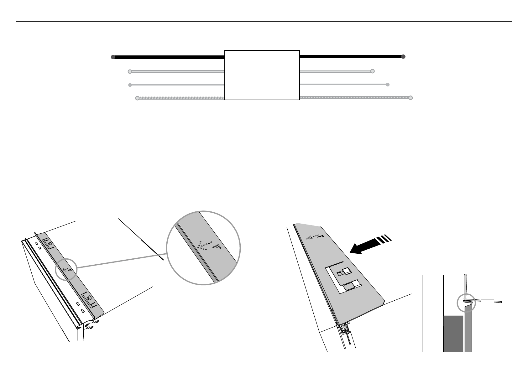
IMPORTANT!
The enclosed cavity bracket is fitted before installation in order
to conceal the gap at the top of the cavity left after installation.
Ensure the cavity panel bracket
is positioned so that the “F”
arrow is pointing towards the
front of the chassis.
Firmly push the bracket so that
the prongs engage with the top
tabs and it clicks into place.
Ensure the top trim
seal is facing forward
after attaching the
bracket.
IMPORTANT!
Ensure the prongs have not
been driven down into the
chassis as this will damage
the lid below.
1 2
11
!0 RECOMMENDED METHOD (A) - SECURE WITHOUT DRAWER REMOVAL (FRAMELESS CABINETRY ONLY)
NOW CHOOSE WHICH INSTALLATION METHOD (A) OR (B)
IS MORE SUITABLE FOR YOUR CABINETRY...
A
A
A
B
B
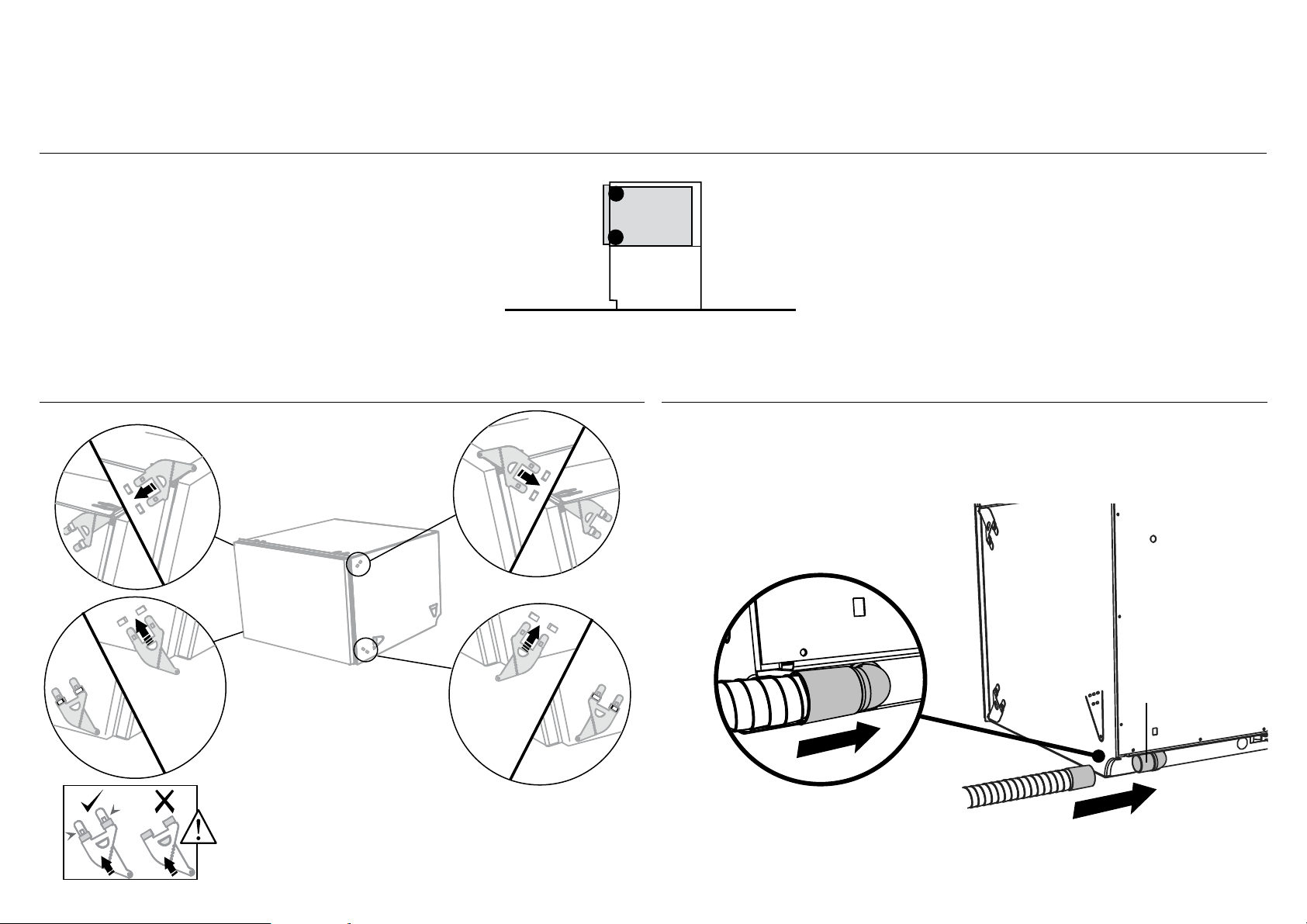
Clip all four side mounting
brackets into their slots using a
flat-bladed screwdriver. Ensure
they’re securely fitted before
sliding product into cavity.
The mounting slots are in pairs,
one on each side diagonally
across the product. A bracket
must match A slot and B bracket
must match B slot.
When fitting brackets, ensure the
ends are not pushed down into
the chassis.
B
AB
!0-A ATTACH SIDE MOUNTING BRACKETS !1-A ATTACH VENTING HOSE
Fitted Elbow
Check that the fitted elbow is
rotated left or right (depending
on the direction of the routing),
then ensure the venting hose is
securely attached to it.
12
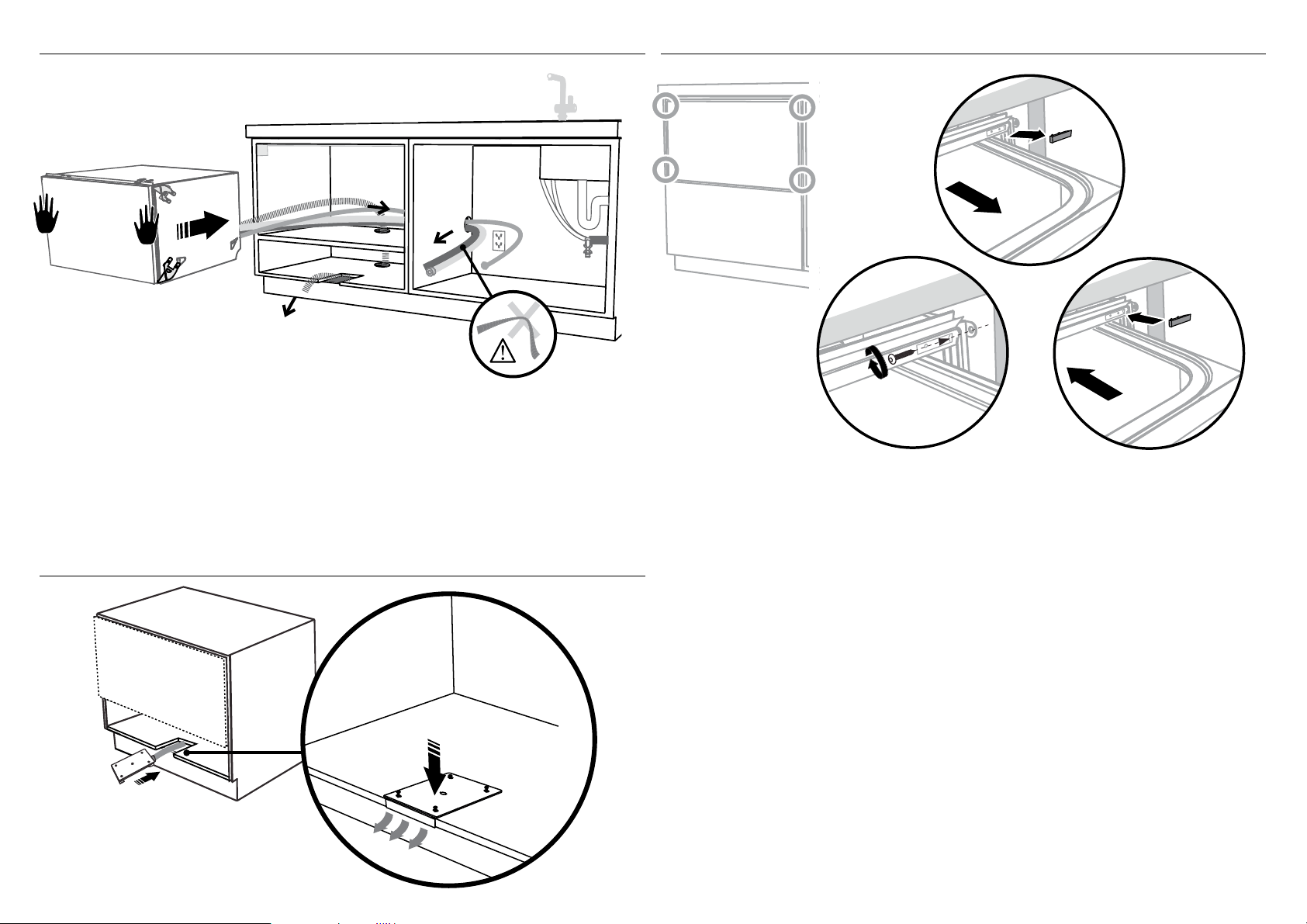
As you push product in, pull through hoses and
cord, ensuring they don’t get kinked or twisted.
IMPORTANT!
If product cannot be pushed in far enough,
pull out again and rearrange hoses and cord.
Do not use excessive force, as doing so
may squash the hoses and lead to incorrect
operation.
2
1
3
Open the
drawer halfway.
Using a flat
bladed
screwdriver,
prise the grey
rubber plug out
of the trim
moulding.
Replace the grey
rubber plug back into
the trim moulding
and ensure the trim
seal is facing forward.
Repeat for all
four brackets.
Using a small
Philips screwdriver,
screw through the
trim moulding,
securing the side
mounting bracket
to the cabinetry.
Do not damage
the rubber
trimseal.
!3-A SECURE TO THE CABINETRY ON THE SIDES!2-A PULL THROUGH HOSES & MOVE INTO THE CAVITY
!4-A SECURE THE EXTERNAL VENT
Vent hose either
through same cabinet
or adjacent cabinet as
per Step 7b or 7c
After routing the vent hose through
and out the hole cutout, attach and
secure the vent by tightening the
four screws provided.
Air flow
2
1

13
!0 ALTERNATIVE METHOD (B) - SECURE BY DRAWER REMOVAL
!0-A ATTACH VENTING HOSE
Fitted Elbow
Check that the fitted elbow is
rotated left or right (depending
on the direction of the routing),
then ensure the venting hose is
securely attached to it.
As you push product in, pull through hoses and
cord, ensuring they don’t get kinked or twisted.
IMPORTANT!
If product cannot be pushed in far enough,
pull out again and rearrange hoses and cord.
Do not use excessive force, as doing so
may squash the hoses and lead to incorrect
operation.
!1-A PULL THROUGH HOSES & MOVE INTO THE CAVITY
Vent hose either
through same cabinet
or adjacent cabinet as
per Step 7b or 7c
14
2
1
3
4
4
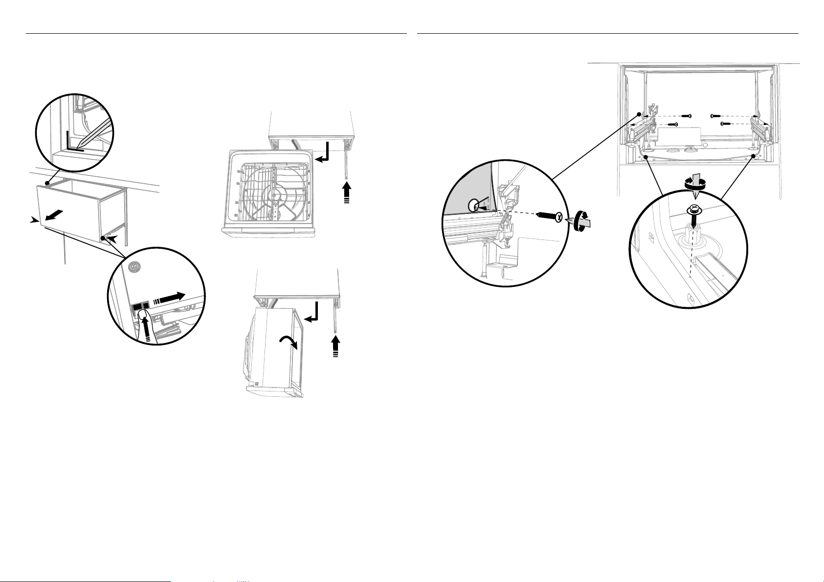
!2-B REMOVE THE DRAWER !3-B SECURE TO THE CABINETRY ON THE SIDES
100 mm
To prevent kinked hoses
Either sit the drawer down on the left
hand side (recommended) or rotate the
drawer clockwise, resting it on its side after
removal.
Press the release tabs in
on either side and push
back to release drawer
from runners.
Lift drawer off runners.
Push drawer
runners back in
on either side.
Push drawer
runners back
in on either
side.
Sit the drawer down
Rotate the drawer
clockwise (max. 90
o
)
and rest on side.
1
2
The product has three
pairs of fixing points:
Ensure the sound insulation
is repositioned correctly.
a pair of fixing
holes either side on the bottom
(use 38 mm fixing screws &
washers)
two pairs of formed
brackets on either side
of the chassis
(use 16 mm screws)
15
1
2
3
4
100 mm
!4-B REFIT THE DRAWER ONTO THE RUNNERS
!5-B SECURE THE EXTERNAL VENT
Before refitting the
drawer, ensure the hoses
are not twisted and the
latches at the rear of
each drawer runner are
facing forward.
Lift or rotate anti-clockwise the
drawer back onto the drawer runners
on either side.
Pull the release tabs forward on both
sides 100 mm. Ensure the tabs are fully
pulled forward and click into place.
Release tab
After routing the vent hose through
and out the hole cutout, attach and
secure the vent by tightening the
four screws provided.
Air flow
2
1
16
!6 INSTALLING A CUSTOM FRONT DRAWER PANEL
1
1
2
Electrical Shock Hazard
WARNING!
Before continuing, ensure that the product is
disconnected from the power supply.
Failure to follow this warning may result in
electrical shock, injury or fire.
3
1
1
!6-A REMOVE PANEL BRACKET FROM PRODUCT
Remove side pins and gently
pull off the panel bracket
slightly.
Remove the Knock-to-Pause
module from the back of the
bracket.
Knock-to-Pause module
Side Pin
!6-B REMOVE THE KNOCK-TO-PAUSE MODULE
1 Disconnect the Earth Wire
from the bracket
2 Unplug the Knock-to-Pause module
from the controller.
17
2
3
16mm (x6)
!6 INSTALLING CUSTOM FRONT DRAWER PANELS
1
2
16mm (x3)
!6-C ATTACH CUSTOM PANELS TO PANEL BRACKETS
There must be at least
3 screws used each side.
Align bottom of each custom
panel with the bottom of each
bracket.
!6-D ATTACH KNOCK-TO-PAUSE MODULE
TO CUSTOM PANEL
IMPORTANT!
●
Ensure the Knock-To-Pause
module is orientated correctly
before attaching.
●
Ensure the module is centralized
in the holes and not in contact
with the bracket.
Attach the Knock-To-Pause
module to the back of the custom
panel through the 3 holes cut into
the panel bracket as shown.
Use all 3 screws provided.

18
!6 INSTALLING CUSTOM FRONT DRAWER PANELS
!6-E CONNECT THE KNOCK-TO-PAUSE MODULE
TO THE CONTROLLER
!6-G ATTACH CUSTOM PANEL TO PRODUCT
!6-F RECONNECT THE EARTH WIRE TO THE
PANEL BRACKET
!6-H ADJUST CUSTOM PANEL HEIGHT TO
ALIGN CABINETRY GAPS
2
2
1
Controller
Ensure the Knock-To-Pause Module
Cable is connected to the UI1 Port.
Electrical Shock Hazard
WARNING!
To earth the panel bracket, connect the earth
wire from the product to one of the tabs.
Any custom metal component (e.g. handle)
that extends past the rubber seal must be
earthed too.
Failure to follow these warnings may result
in electrical shock, injury or fire.
Reconnect the
Earth Wire to the
Panel bracket.
+ or - 2mm
Push the Custom Panel on to
the drawer and reinsert the
side pins on each side.
With the front panels fitted, insert
an appropriately sized Philips
screwdriver into the hole above the
side pin and rotate the panels up or
down to align the gaps
in your cabinetry.
Repeat on the other side if necessary.
Each panel has a maximum travel of
2mm up or down.
IMPORTANT!
Ensure that you maintain a minimum
of 2mm ventilation gap below the
panel.
IMPORTANT!
Ensure the rubber seal between the drawer
and panel is kept in place.
Side Pin
19
!7 THERE ARE TWO DIFFERENT PLUMBING AND DRAINAGE OPTIONS. CHOOSE WHICH IS MORE SUITABLE.
1
2
3
1
2
If space is limited
for fixing, push
hose through drain
hose support
to required height
If space is limited
for fixing, push
hose through drain
hose support
to required height
Dishwasher using drain hose joiner onto sink trap/waste tee
min. radius
200 mm
750 - 882.5 mm
750 - 882.5 mm
min. 500 mm
min. 500 mm
min. radius
200 mm
step 18
step 18
Supplied drain
hose joiner to suit
19 mm waste tee
Ensure drain hose is routed
straight to joiner. Remove excess
drain hose material if necessary.
Do not shorten the inlet hose.
Dishwasher and Ø 38 mm Standpipe
IMPORTANT!
Do not connect the drain hoses
to a Waste Disposal Unit, as this
type of connection may lead to a
blockage in the drain hoses.
750-882.5 mm
750-882.5 mm
38mm
max.
120mm
20
Ensure the supplied
rubber washer is
fitted inside the
coupling.
Tighten coupling
with spanner.
180
o
No leaks!
1
2
min.
10mm
3/4” BSP connector
!8 CONNECT INLET HOSE TO COLD WATER !9 PLUG PRODUCT IN

21
@0 TROUBLESHOOTING
●
Excessive water remaining above the filter plate, after the rinse cycle. (This is displayed as an A3 fault. See user guide ‘How to attend to a fault’)
Check for a kinked drain hose, blocked or incorrectly drilled out waste connection, highloop not properly installed, drain hose not routed correctly or spray arm not in place.
●
No water supply. (This is displayed as an A1 fault. See user guide ‘How to attend to a fault’)
Check water is connected and turned on.
●
The dishwasher is beeping continuously
There is a fault. See section ‘How to attend to a fault’in the User guide for further information and instructions.
●
No program indicator lights up when the drawer is opened
Ensure power is connected and is switched on. If it is and still no indicator lights up, see the ‘Preference options’ section of the ‘Quick start guide’.
An option called ‘Open drawer auto power-on’ may need to be turned on.
●
Water around water supply and drainage connections
Check connections, existing plumbing and hoses for leaks. Check rubber washer and hose clamp are correctly fitted.
●
If product is tipping
Ensure the product is secured to the cabinetry.
●
Drawer doesn’t close properly
Ensure nothing is obstructing the drawer from closing properly eg hoses or drawer latches.
●
If a problem occurs, consult the ‘Troubleshooting’ section of the User guide.
●
If after checking these points you still need assistance, please refer to the Service & Warranty book for warranty details and your nearest Authorised Service Centre, or contact us through our
website, listed below.

22
@1 FINAL CHECKLIST
TO BE COMPLETED BY THE INSTALLER
Complete and keep for safe reference:
Model
Serial No.
Purchase Date
Purchaser
Dealer Address
Installer’s Name
Installer’s Signature
Installation Company
Installation Date
Check all parts are installed.
Ensure that all panels and parts thereof are secure and final electrical tests have been
conducted in accordance with local electrical regulations.
Ensure product is level, securely fastened to the cabinetry and opens and closes freely.
The drawers must be free to fully close with no resistance from the cabinetry.
Ensure inlet hose to water supply has supplied rubber washer fitted, and that it’s
tightened a further half turn after seal contact.
Ensure any knockouts or plugs in drain connection have been drilled out and drain
connection has been made.
The drain hose joiner must not support the weight of excess hose material. Keep drain
hose as fully extended as possible to prevent sagging. Any excess length of drain hose
should be kept on the dishwasher side of the highloop.
If connecting the drain hose to the sink trap, ensure the Highloop is a minimum 150 mm
higher than the drain hose joiner.
Ensure any packaging or tape securing the racks is removed from the drawers.
Water softener models only: adjust the water softener setting from the default
setting to suit the water hardness of the area.
See the Quick start guide and section ‘Water softener’ in the User guide.
Turn on the power and water supplies, then open the drawer. You should hear a
beep and see a program indicator light up on the control panel.
Check the spray arms are in place, mounted correctly and free to rotate, by
physically rotating by hand.
Add three cups of water into the drawer. Press
until the indicator of the ‘Rinse’
program lights up. Close the drawer and press to start the program.
When the test cycle is in process check the knock sensor is working by knocking
twice on the door to pause the wash program.
After the Rinse program has finished, ensure the dishwasher has run and drained
correctly.
Check the water supply has correctly shut off and drainage connection for leakage.
Spray arm
Copyright © Fisher & Paykel Appliances 2017. All rights reserved.
The product specifications in this booklet apply to the specific products
and models described at the date of issue. Under our policy of continuous
product improvement, these specifications may change at any time. You
should therefore check with your Dealer to ensure this booklet correctly
describes the product currently available.
FISHERPAYKEL.COM