www.lg.com
Please read the safety information carefully before using the product.
LED LCD Monitor (LED Monitor) Model List
OWNER'S MANUAL
LED LCD Monitor
(LED Monitor*)
*LG LED Monitors are LCD Monitors with LED Backlighting.
24MB34PY
24MB34D

2
ENGLISH
CONTENTS
CONTENTS
3 ASSEMBLING AND PREPARING
3 Unpacking
4 Partsandbuttons
5 SettinguptheMonitorset
5 - AttachingtheStandBase
5 - Detachingthestandbase
6 SettinguptheMonitorset
6 - AttachingtheStandBase
6 - DetachingtheStandBase
7 - Detachingthestandbody
7 - Usingthecableholder
7 - Mountingonatable
8 - Adjustingtheangle
10 - Adjustingthestandheight
10 - UsingtheKensingtonlockingdevice
11 - Swivelstand
11 - UsingthePivotfunction
12 - Mountingonawall
13 USING THE MONITOR SET
13 ConnectingtoaPC
13 - D-SUBconnection
13 - DVI-Dconnection
14 - DisplayPortconnection
15 - Peripheraldeviceconnection
16 CUSTOMIZING SETTINGS
17 CustomizingSettings
20 TROUBLESHOOTING
22 SPECIFICATIONS
22 24MB34PY
23 24MB34D
24 PresetModes(Resolution)
24 D-SUB/DVITiming
24 DPTiming
25 D-SUB/DVITiming
25 Indicator
3
ASSEMBLING AND PREPARING
ENGLISH
ASSEMBLING AND PREPARING
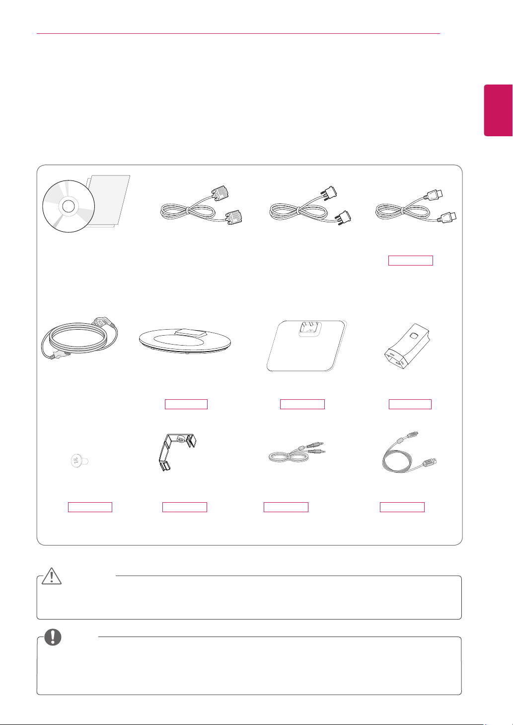
Unpacking
Checkyourproductboxforthefollowingitems.Ifthereareanymissingaccessories,contactthelocaldealerwhereyou
purchasedyourproduct.Theillustrationsinthismanualmaydifferfromtheactualproductandaccessories.
Donotuseanyunapprovedaccessoriestoensurethesafetyandproductlifespan.
Anydamagesorinjuriesbyusingunapprovedaccessoriesarenotcoveredbythewarranty.
Theaccessoriessuppliedwithyourproductmayvarydependingonthemodel.
Productspecificationsorcontentsinthismanualmaybechangedwithoutpriornoticeduetoupgradeof
productfunctions.
CAUTION
NOTE
Stand Base Stand BodyStand Base
CD(Owner's Manual) /
Card
D-SUB Cable
(Thiscableisnot
includedinall
countries.)
(Dependingonthecountry) (Dependingonthecountry)
Power Cord
DVI-D Cable
(Thiscableisnot
includedinall
countries.)
DisplayPort Cable
24MB34PY
(Thiscableisnot
includedinall
countries.)
One Screw Cable Holder USB CableAudio Cable
24MB34D 24MB34D24MB34PY
24MB34PY 24MB34PY 24MB34PY 24MB34PY
4
ASSEMBLING AND PREPARING
ENGLISH
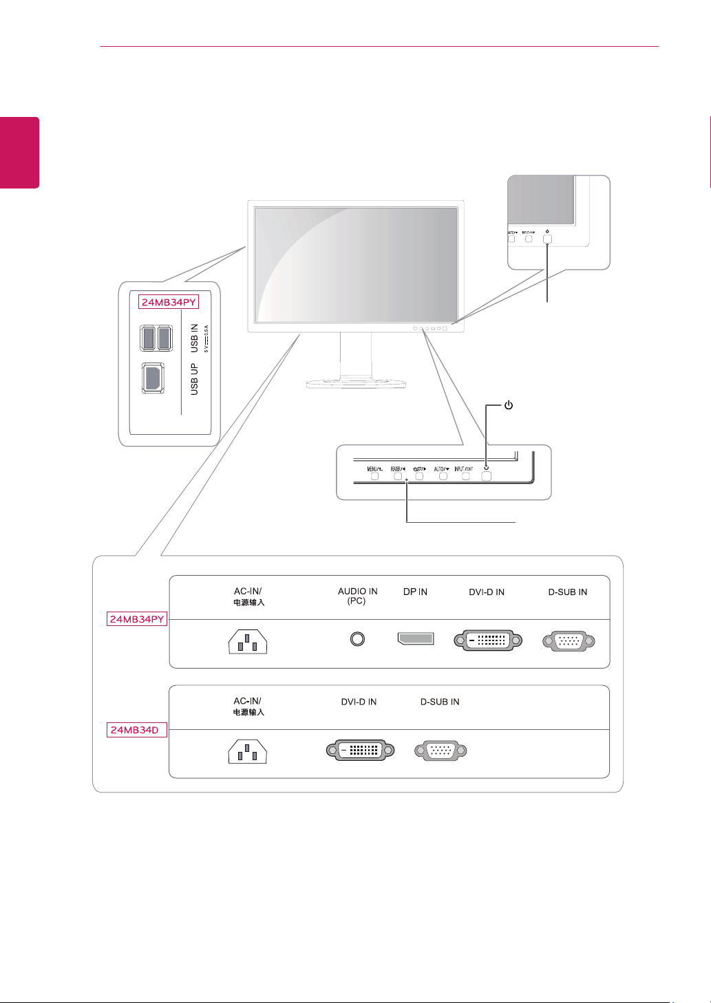
Parts and buttons
(PowerButton)
Power Indicator
LEDOn:Powerison
LEDOff:Powerisoff
FrontSideButtons
5
ASSEMBLING AND PREPARING
ENGLISH
Stand Base
Stand Base
Stand Base
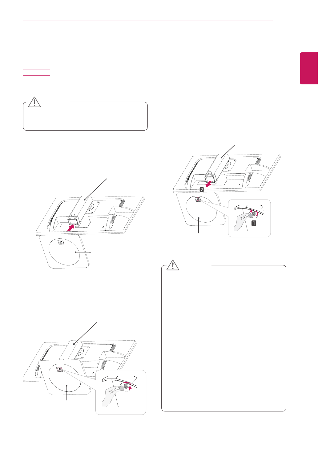
Setting up the Monitor set
Attaching the Stand Base
24MB34PY
1
PlacetheMonitorsetwiththescreensidedownon
aflatandcushionedsurface.
Stand Base
Stand Body
Stand Body
Stand Base
Stand Body
Toprotectthescreenfromscratches,coverthe
surfacewithasoftcloth.
3
Usingacoin,turnthescrewclockwisetosecurethe
stand base.
2
Checktheposition (at the front and rear) ofthe
standbody, then mountthestand baseonthe
stand body asshowninthefigure.
CAUTION
Stand Base
Illustrationsinthisdocumentrepresenttypical
procedures,sotheymaylookdifferentfromthe
actualproduct.
Donotcarrythemonitorupsidedownbyjust
holdingthestandbase.Thismaycausethemoni-
tortofalloffthestandandcouldresultinper-
sonalinjury.
Whenliftingormovingthemonitor,donottouch
themonitorscreen.Theforceappliedtothemoni-
torscreenmaycausedamagetoit.
Donotapplyforeignsubstances(oils,lubricants,
etc.)tothescrewpartswhenassemblingthe
product.(Doingsomaydamagetheproduct.)
Applyingexcessiveforcewhentighteningscrews
maycausedamagetothemonitor.Damage
causedinthiswaywillnotbecoveredbythe
productwarranty.
Detaching the stand base
1
Placethemonitor'sscreenfacedown.
Toprotectthescreenfromscratches,coverthe
surfacewithasoftcloth.
2
Usingacoin,turnthescrewinthestandbasecoun-
terclockwise.Detachthestand base fromthestand
body.
CAUTION
6
ASSEMBLING AND PREPARING
ENGLISH
AttachtheStand Bodytothemonitorset.
AttachtheStand Base.
Tiedownthebaselocktoperpendicularity
direction.
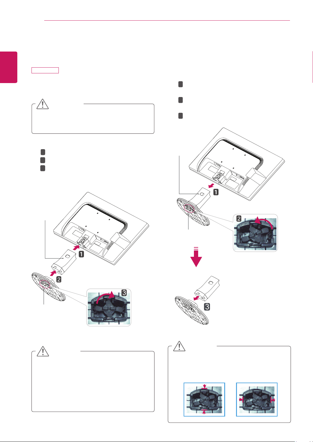
Setting up the Monitor set
Attaching the Stand Base
24MB34D
1
PlacetheMonitorsetwiththescreensidedownon
aflatandcushionedsurface.
Layafoammatorsoftprotectiveclothonthe
surfacetoprotectthescreenfromdamage.
CAUTION
2
Stand Base
Stand Body
1
2
3
Detaching the Stand Base
1
PlacetheMonitorsetwiththescreensidedownon
aflatandcushionedsurface.
Stand Base
Stand Body
PushingthePUSHbutton,TaketheStand Body
fromthemonitorset.
Changeyourlockontheproductasitfollows
andturnitinthearrowdirection.
PullouttheStand Base.
1
2
3
2
Ifyoucan'treleasethestandbaseeventhe
lockingknobisatareleaseposition,Pleasepush
theindicatedknobdownandretryit.
CAUTION
Thisillustrationdepictsthegeneralmodelof
connection.Yourmonitormaydifferfromthe
itemsshowninthepicture.
Donotcarrytheproductupsidedownholding
onlythestandbase.Theproductmayfallandget
damagedorinjureyourfoot.
CAUTION
7
ASSEMBLING AND PREPARING
ENGLISH
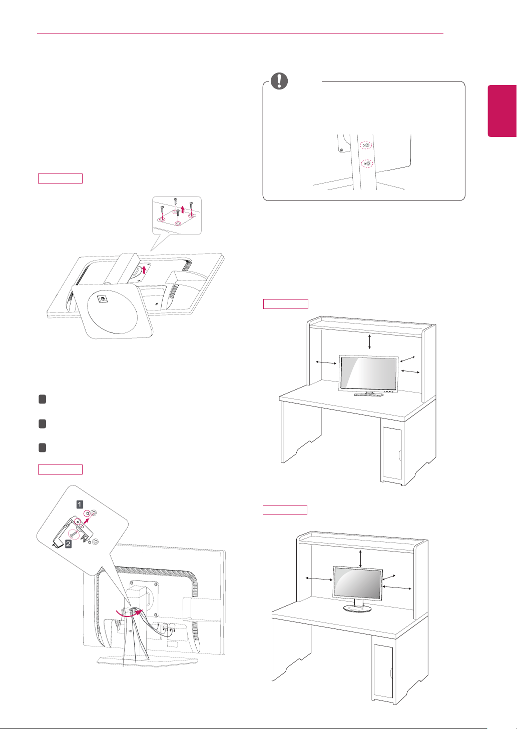
Mounting on a table
1
Lift the monitor and place it on the table in an
upright position.
Install at least 100 mm (3.94 inches) away from
the wall to ensure sufficient ventilation.
100 mm
(3.94 inches)
100 mm
(3.94 inches)
100 mm
(3.94 inches)
100 mm
(3.94 inches)
100 mm
(3.94 inches)
100 mm
(3.94 inches)
100 mm
(3.94 inches)
100 mm
(3.94 inches)
Detaching the stand body
1
Place the monitor's screen face down. To protect the
screen from scratches, cover the surface with a soft
cloth.
2
Using a screwdriver, remove the four screws and
detach the stand from the monitor.
Using the cable holder
Fix the Knob (Cable holder) to the
Hole(Hingebody).
1
2
3
Use one screw to fix the Cable Holder and
monitor set.
Close the Cable holder.
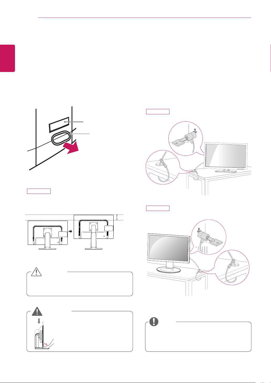
NOTE
y
The holes are used for wall mount bracket.
y
Varies depending upon your country or model.
24MB34PY
24MB34PY
24MB34PY
24MB34D
8
ASSEMBLING AND PREPARING
ENGLISH
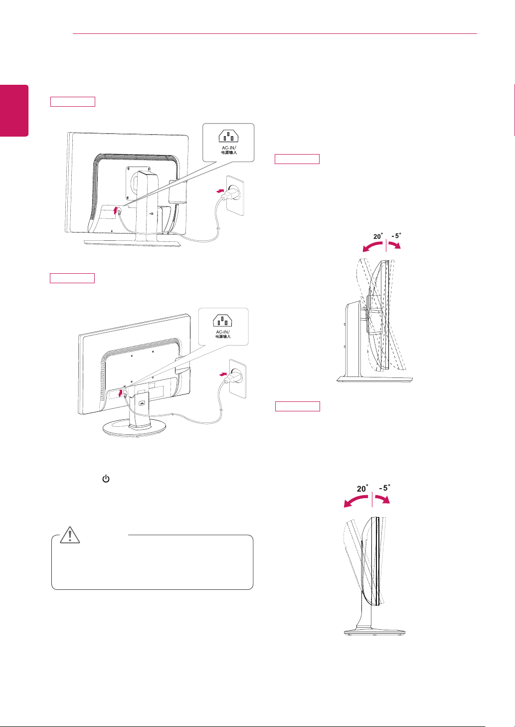
3
Press the (Power) button on the front of the
monitor to turn on the monitor.
y
Unplug the power cord prior to moving or install-
ing the monitor. There is risk of electric shock.
CAUTION
Adjusting the angle
1
Place the monitor mounted on the stand base in an
upright position.
2
Adjust the angle of the screen. The angle of the
screen can be adjusted up to 5° forwards and 20°
backwards for a comfortable viewing experience.
Front SideRear Side
2
Adjust the angle of the screen. The angle of the
screen can be adjusted up to 5° forwards and 20°
backwards for a comfortable viewing experience.
2
Connect the Power cord to the monitor, then plug
the power cord into the wall outlet.
Front SideRear Side
24MB34PY
24MB34PY
24MB34D
24MB34D
9
ASSEMBLING AND PREPARING
ENGLISH
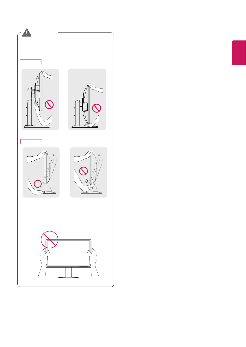
y
To avoid injury to the fingers when adjusting the
screen, do not hold the lower part of the moni-
tor's frame as illustrated below.
y
Be careful not to touch or press the screen area
when adjusting the angle of the monitor.
WARNING
24MB34PY
24MB34D
10
ASSEMBLING AND PREPARING
ENGLISH
Using the Kensington locking device
The connector for the Kensington lock is located on the
rear of the monitor.
For more information on installation and usage, refer to
the Kensington lock user manual or visit the website at
http://www.kensington.com.
Connect the monitor to the table with the Kensington
lock cable.
y
Using the Kensington lock is optional. The acces-
sories can be purchased at your local electronics
store.
NOTE
y
Once the pin is removed, it is not necessary to re-
insert it to adjust the height.
3
The height can be adjusted up to 4.72 inches.
y
Do not put your finger between
the screen and the base (chas-
sis) when adjusting the screen's
height.
CAUTION
WARNING
4.72 inches
Adjusting the stand height
1
Place the monitor mounted on the stand base in an
upright position.
2
Remove the tape attached at the bottom rear of
the stand body, then pull out the locking pin.
Tape
Locking Pin
Stand Body
24MB34PY
24MB34PY
24MB34D
11
ASSEMBLING AND PREPARING
ENGLISH
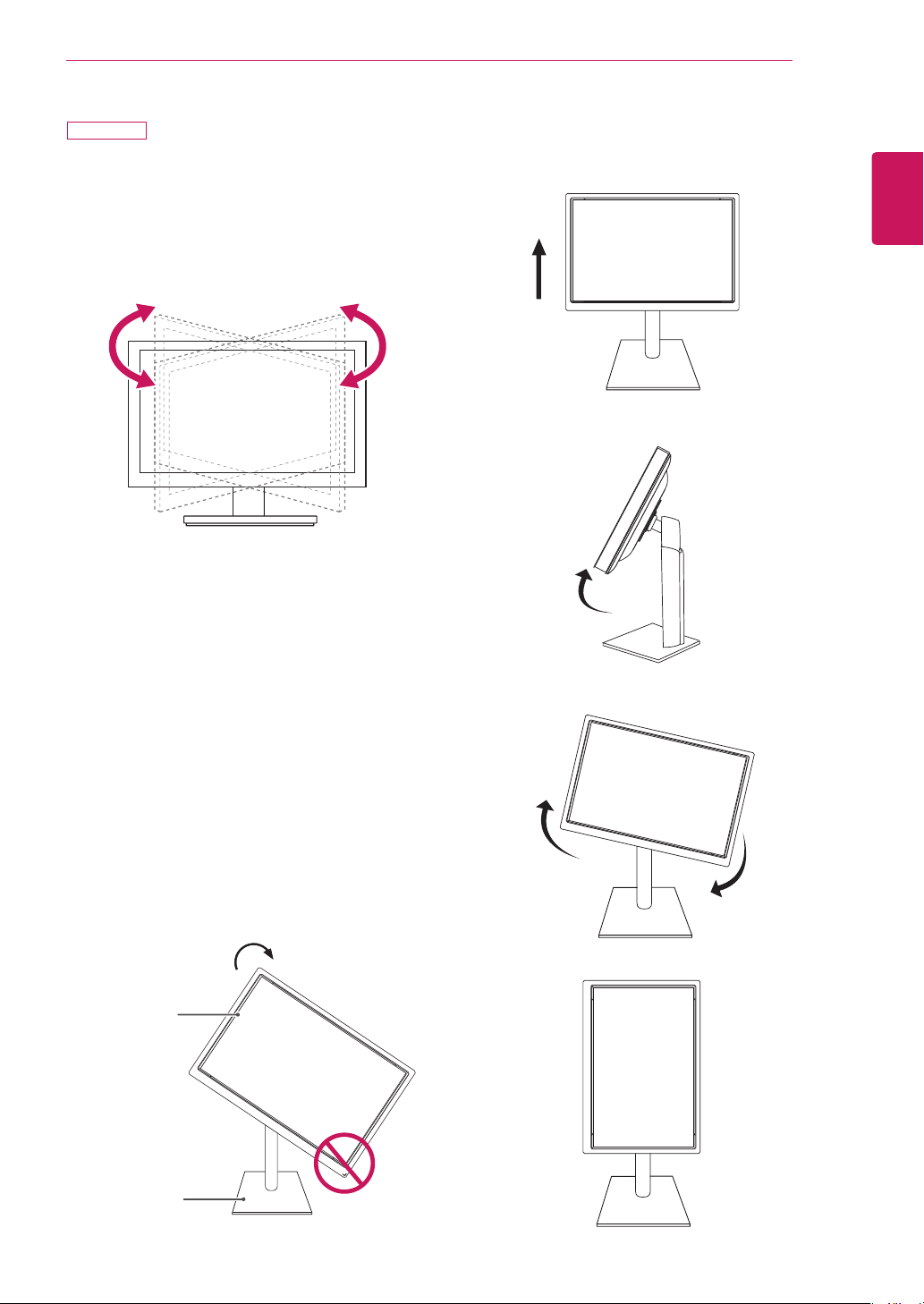
Swivel stand
y
Image shown may differ from your Monitor set.
1
Swivel 355 degrees and adjust the angle of the
Monitor set to suit your view.
1
Lift the monitor to its highest height to utilize the
Pivot function.
Using the Pivot function
The pivot function allows you to rotate the screen 90
degrees clockwise.
2
Landscape & Portrait : You can rotate the panel 90°
clockwise. Please be cautious and avoid contact be-
tween the monitor head and the Stand Base when
rotating the screen to access the Pivot function. If
the monitor head touches the Stand Base, then the
Stand Base could crack.
Head
section
Stand
section
3
Be careful with the cables when rotating the screen.
24MB34PY
12
ASSEMBLING AND PREPARING
ENGLISH
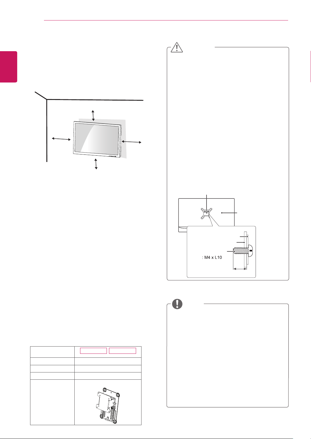
Mounting on a wall
For proper ventilation, allow a clearance of 100 mm
(3.94 inches) on each side and from the wall. Detailed
instructions are available from your dealer, see the
optional Tilt Wall Mounting Bracket Installation and
Setup Guide.
If you intend to mount the Monitor set to a wall, attach
Wall mounting interface (optional parts) to the back of
the set.
When you install the Monitor set using a wall mounting
interface (optional parts), attach it carefully so it will not
drop.
1
Please, Use the screw and wall mount interface in
accordance with VESA Standards.
2
If you use screw longer than standard, the monitor
might be damaged internally.
3
If you use improper screw, the product might be
damaged and drop from mounted position. In this
case, LG Electronics is not responsible for it.
4
VESA compatible only with respect to screw
mounting interface dimensions and mounting screw
specifications.
5
Please use VESA standard as below.
y
784.8 mm (30.9 inch) and under
* Wall Mount Pad Thickness : 2.6 mm
* Screw :
Φ
4.0 mm x Pitch 0.7 mm x
Length 10 mm
y
787.4 mm (31.0 inch) and above
* Please use VESA standard wall mount pad and
screws.
y
Use the screws that are listed on the VESA
standard screw specifications.
y
The wall mount kit will include an installation
manual and necessary parts.
y
The wall mount bracket is optional. You can
obtain additional accessories from your local
dealer.
y
The length of screws may differ depending on
the wall mount. Be sure to use the proper length.
y
For more information, refer to the instructions
supplied with the wall mount.
NOTE
Model
24MB34PY 24MB34D
VESA (A x B)
100 x 100
Standard screw
M4
Number of screws
4
Wall Mount Plate
(Optional)
RW120
y
Disconnect the power cord first, and then move
or install the Monitor set. Otherwise electric
shock may occur.
y
If you install the Monitor set on a ceiling or
slanted wall, it may fall and result in severe
injury.
y
Use only an authorized LG wall mount and
contact the local dealer or qualified personnel.
y
Do not over tighten the screws as this may
cause damage to the Monitor set and void your
warranty.
y
Use only screws and wall mounts that meet
the VESA standard. Any damages or injuries by
misuse or using an improper accessory are not
covered by the warranty.
y
Screw length from outer surface of back cover
should be under 0.31 inches .
CAUTION
Back Cover
Wall mount Pad
Wall mount Pad
Back Cover
Standard screw
Max.0.31 inches
100 mm
(3.94 inches)
100 mm
(3.94 inches)
100 mm
(3.94 inches)
100 mm
(3.94 inches)
13
USING THE MONITOR SET
ENGLISH
USING THE MONITOR SET
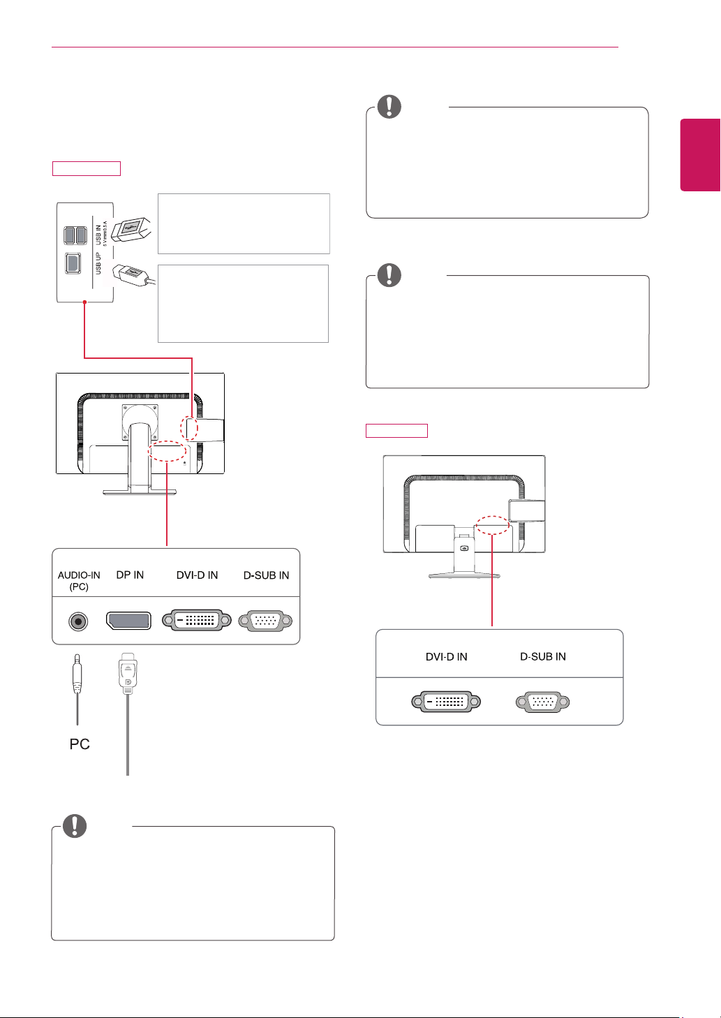
Connecting to a PC
YourMonitorsetsupportsPlug&Play*.
*Plug&Play:APCrecognizesaconnecteddevice
thatusersconnecttoaPCandturnon,without
deviceconfigurationoruserintervention.
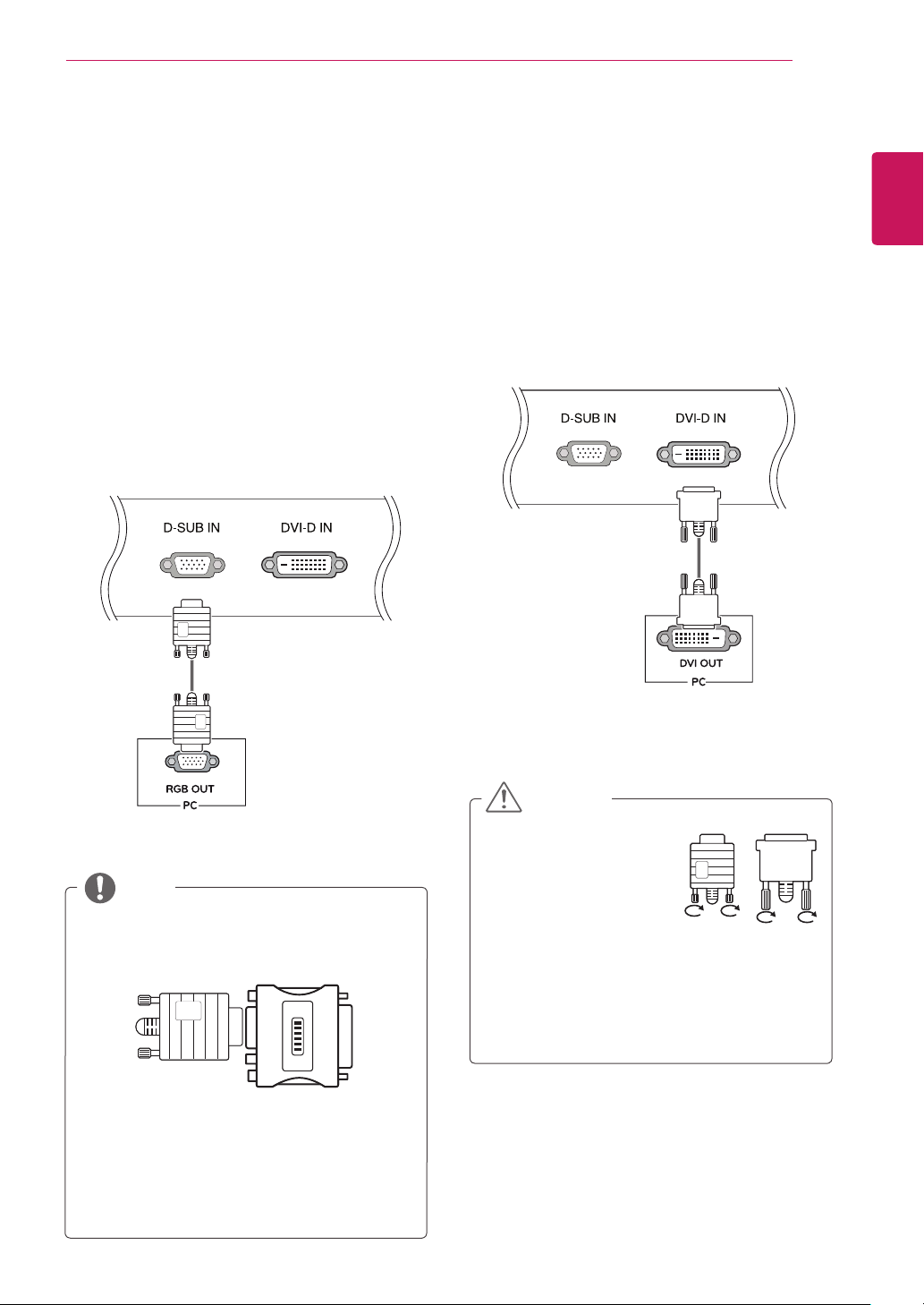
D-SUB connection
TransmitsanalogvideofromyourPCtotheMonitorset.
ConnectthePCandtheMonitorsetwiththesupplied
D-sub15pinsignalcableasshowninthefollowing
illustrations.
Mac adapter
ForAppleMacintoshuse,aseparateplugadapter
isneededtochangethe15pinhighdensity(3
row)D-SUBVGAconnectoronthesuppliedcable
toa15pin2rowconnector.
WhenusingaD-Subsignalinputcableconnector
forMacintosh
NOTE
DVI-D connection
TransmitsadigitalvideosignalfromyourPCtothe
Monitorset.ConnectthePCandtheMonitorsetwitha
DVIcableasshowninthefollowingillustrations.
Connectthesignalinput
cableandtightenitby
turningthescrewsclockwise.
Donotpressthescreenwith
yourfingerforalongtime
asthismayresultintemporarydistortiononthe
screen.
Avoiddisplayingafixedimageonthescreenfor
alongperiodoftimetopreventimageburn.Use
ascreensaverifpossible.
CAUTION
14
USING THE MONITOR SET
ENGLISH
"Self Image Setting" Function.
Thisfunctionprovidestheuserwithoptimal
displaysettings.Whentheuserconnects
themonitorforthefirsttime,thisfunction
automaticallyadjuststhedisplaytooptimal
settingsforindividualinputsignals.(Only
supportedinAnalogMode)
‘AUTO’ Function.
Whenyouencounterproblemssuchasblurry
screen,blurredletters,screenflickerortilted
screenwhileusingthedeviceorafterchanging
screenresolution,presstheAUTOfunction
buttontoimproveresolution.(Onlysupportedin
AnalogMode)
NOTE
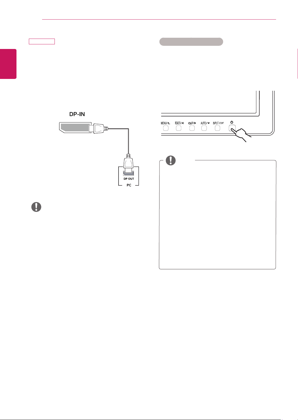
Self Image Setting Function
Pressthepowerbuttononthebottompaneltoturnthe
poweron.Whenmonitorpoweristurnedon,the"Self
Image Setting"Functionisexecutedautomatically.(Only
supportedinAnalogMode)
Theremaybenovideooraudiooutputdepending
ontheDPversionofthePC.
y
IfyouusegenericcablesnotcertifiedbyLG,the
screenmaynotdisplayortheremaybeimage
noises.
DisplayPort connection
Transmitsthedigitalvideoandaudiosignalsfromyour
PCtothemonitor.ConnectyourPCtothemonitorus-
ingtheDisplayPortcableasillustratedbelow.
Pressthemenubuttonandthenselecttheinputoption
fromtheinputmenu.
NOTE
24MB34PY
15
USING THE MONITOR SET
ENGLISH
Peripheraldevicesaresoldseparately.
TheUSBportsontheleftandbottomofthe
monitorcanbeusedtoconnectthekeyboard,
mouse,andotherUSBdevices.
Peripheral device connection
Connectperipheraldevicestothemonitor.
NOTE
NOTE
Headphonesorspeakersmaynotworknormally,
dependingontheserverPCsettings.
Virtualsolutionsmayaffectthefunctionsor
speedofthespecificUSBstoragedevice.
NOTE
Themonitor'sUSBterminalsupportsUSB2.0and
highspeedcables.
DP=DisplayPort
TwoUSBDownstreamports
Connecttheseportstoamouse,USB
keyboard,memorystickwithcurrent
specunder100mA.
OneUSBUpstreamport
Connectthisporttothedown-
streamportofacomputer,laptopor
USBmonitor(YourcomputerorUSB
monitormustsupportUSBandhave
USBports).
(Not Provided)
24MB34D
24MB34PY
16
CUSTOMIZING SETTINGS
ENGLISH
CUSTOMIZING SETTINGS
1
PressthedesiredbuttononthebottomoftheMonitorset.
2
ChangethevalueofthemenuitembypressingthebuttonsonthebottomoftheMonitorset.
Toreturntotheuppermenuorsetothermenuitems,usetheuparrow( )button.
3
SelectEXITtoleavetheOSDmenu.
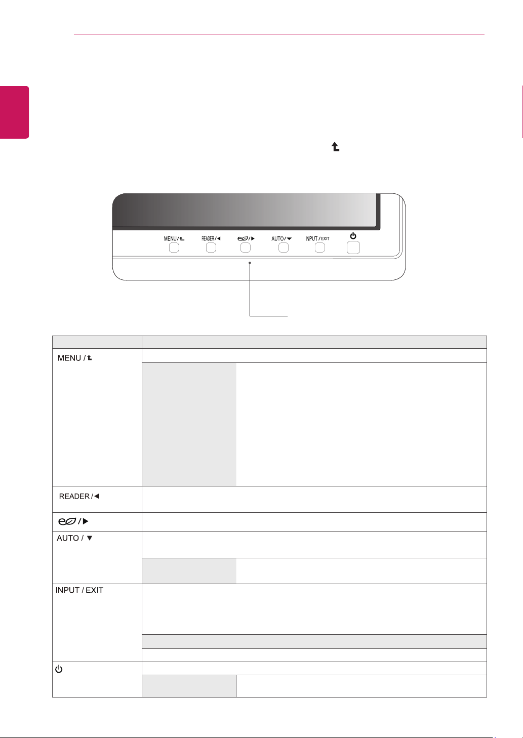
Monitor set Buttons
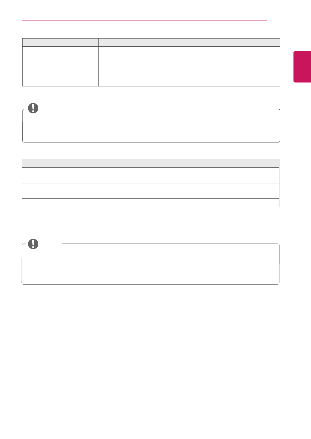
Button Description
Accessesthemainmenus.(Seep.17)
OSD Locked/OSD
Unlocked
Thisfunctionallowyoutolockthecurrentcontrolsettings,sothat
theycannotbeinadvertentlychanged.
PressandholdtheMENUbuttonforseveralseconds.ThenOSDof
“OSDLock”willappear.Afterthat,usercanselectlockorunlockby
pressingleft/rightbutton.
Ifuserselectsthe“Lock”iconbypressingthe“OK”button,the
message“OSDLocked”willappear.Otherwise,“OSDUnlocked”will
appear.Afterselectingthe“Lock”,IfyouwanttochangetoUnlock,
youcanpushthe“MENU”buttonforseveralseconds.Themessage
“OSDUnlocked”willappear.
UsethisbuttontoenterReaderModemenu.Itsfunctionworkstodisplayscreenaspaper-
likepictureforEyecomfort.Ifyouwanttomoreinformation.(Seep.19)
UsethisbuttontoenterSMARTENERGYSAVINGmenu.
(
Seep.19
)
Whenadjustingyourdisplaysettings,alwayspresstheAUTObuttonontheMONITOR
SETUPOSD.(OnlysupportedinAnalogMode)
The best display mode 24MB34PY:1920x1080
24MB34D:1920x1080
Youcanchoosetheinputsignal.
• Whentwoinputsignalsareconnected,youcanselecttheinputsignalyouwant.
• Whenonlyonesignalisconnected,itisautomaticallydetected.Thedefaultsettingis
D-SUB.
EXIT
ExittheOSD(OnScreenDisplay).
(PowerButton)
Turnsthepoweronoroff.
Power Indicator
Thepowerindicatorstayswhiteifthedisplayisrunningproperly(On
Mode).IfthedisplayisinSleepMode,thepowerindicatorblinkswhite.
17
CUSTOMIZING SETTINGS
ENGLISH
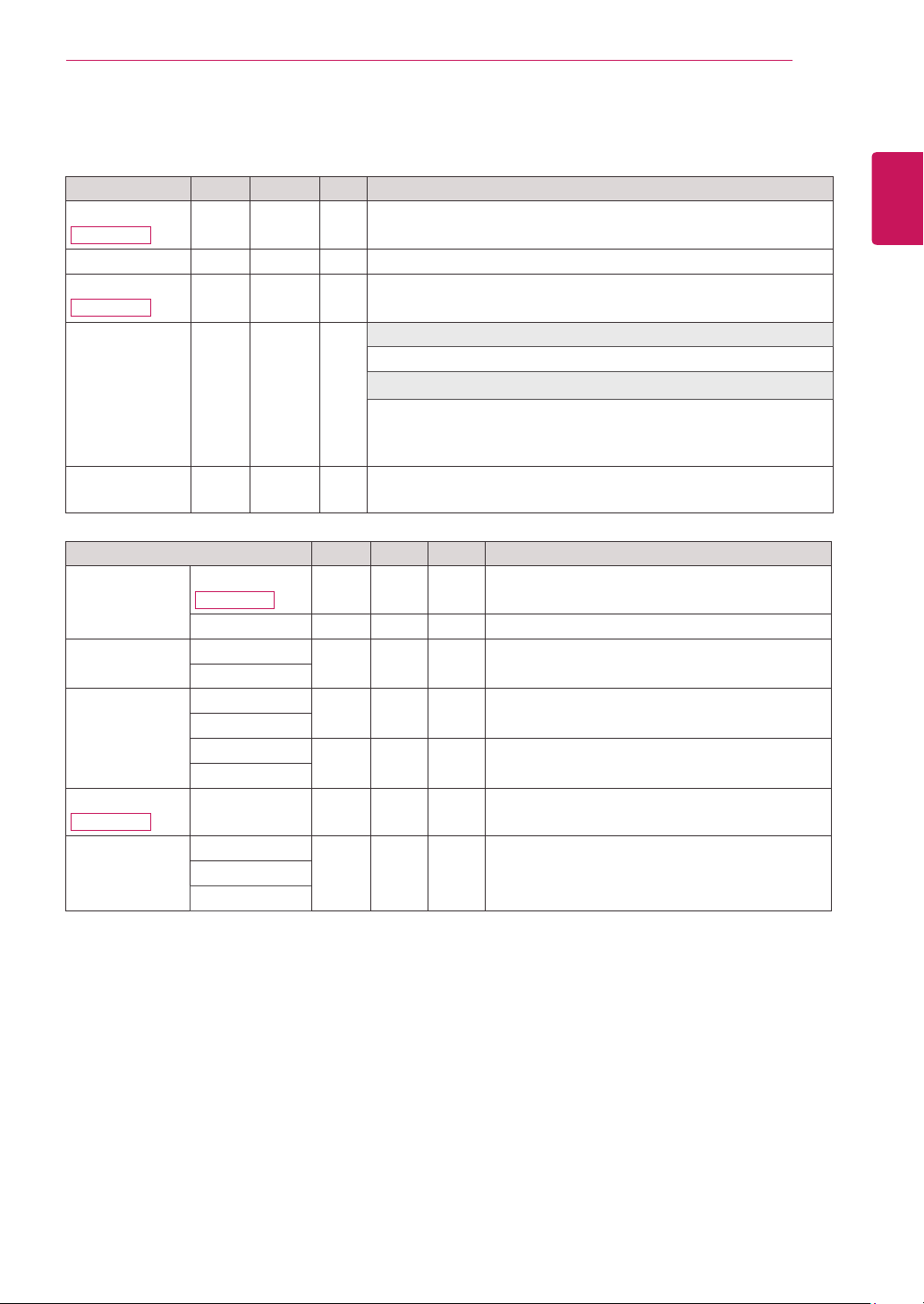
Customizing Settings
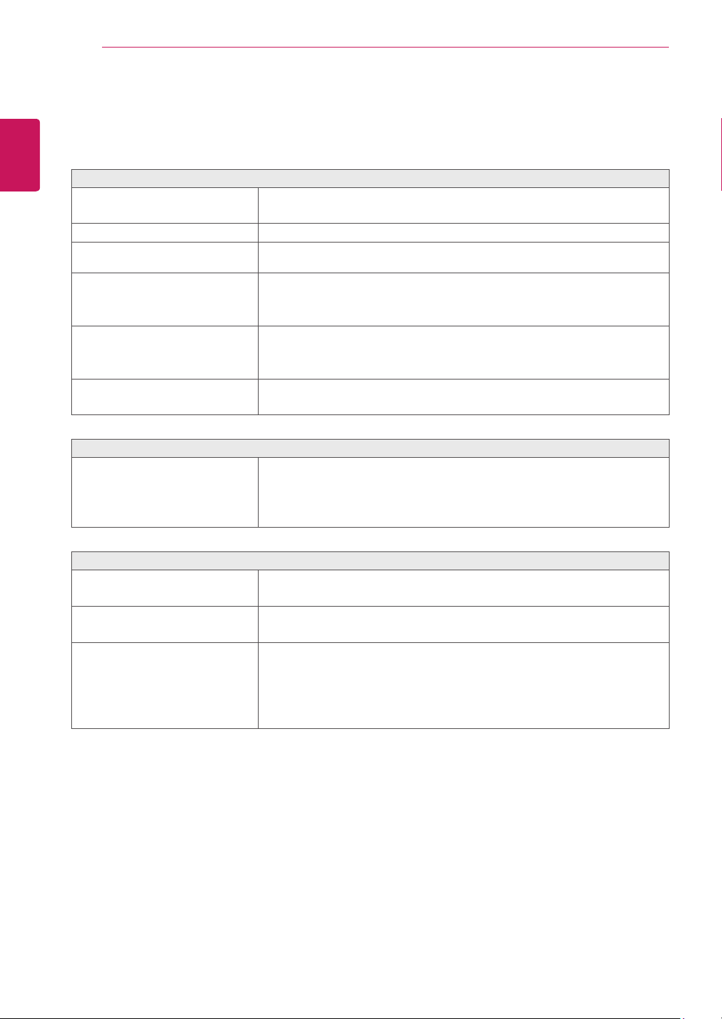
Menu Analog Digital DP Description
Volume
24MB34PY
● ● ●
Toadjustthevolume
Brightness
● ● ●
Toadjustthebrightnessofthescreen
Contrast
24MB34D
● ●
Toadjustthecontrastofthescreen
Wide/Original
● ● ●
Wide
Switchtofullscreenmodeaccordingtoinputimagesignal.
Original
Changetheinputimagesignalratiotooriginal.
*ThisfunctionworksonlyifinputresolutionislowerthanMonitorset
ratio(16:9).
Reset
● ● ●
Restoreallfactorydefaultsettings.Pressthe
◄
,
►
buttonstoreset
immediately.
Menu > Next Menu Analog Digital DP Description
Picture Contrast
24MB34PY
● ● ●
Toadjustthecontrastofthescreen
Sharpness
● ● ●
Toadjusttheclearnessofthescreen
Color Gamma
● ● ●
Tocustomizethecolorofthescreen
Color Temp
Display Horizontal
●
Toadjustthepositionofthescreen
Vertical
Clock
●
Toimprovetheclarityandstabilityofthescreen
Phase
Audio
24MB34PY
Audio Input
●
Toselecttheaudioinput
Others Language
● ● ●
Tocustomizethescreenstatusforauser'soperating
environment
Power Indicator
Off Time Setting
Analog: D-SUB(Analogsignal)input.
Digital: DVI-D(Digitalsignal)input.
DP: DisplayPortinput.
18
CUSTOMIZING SETTINGS
ENGLISH
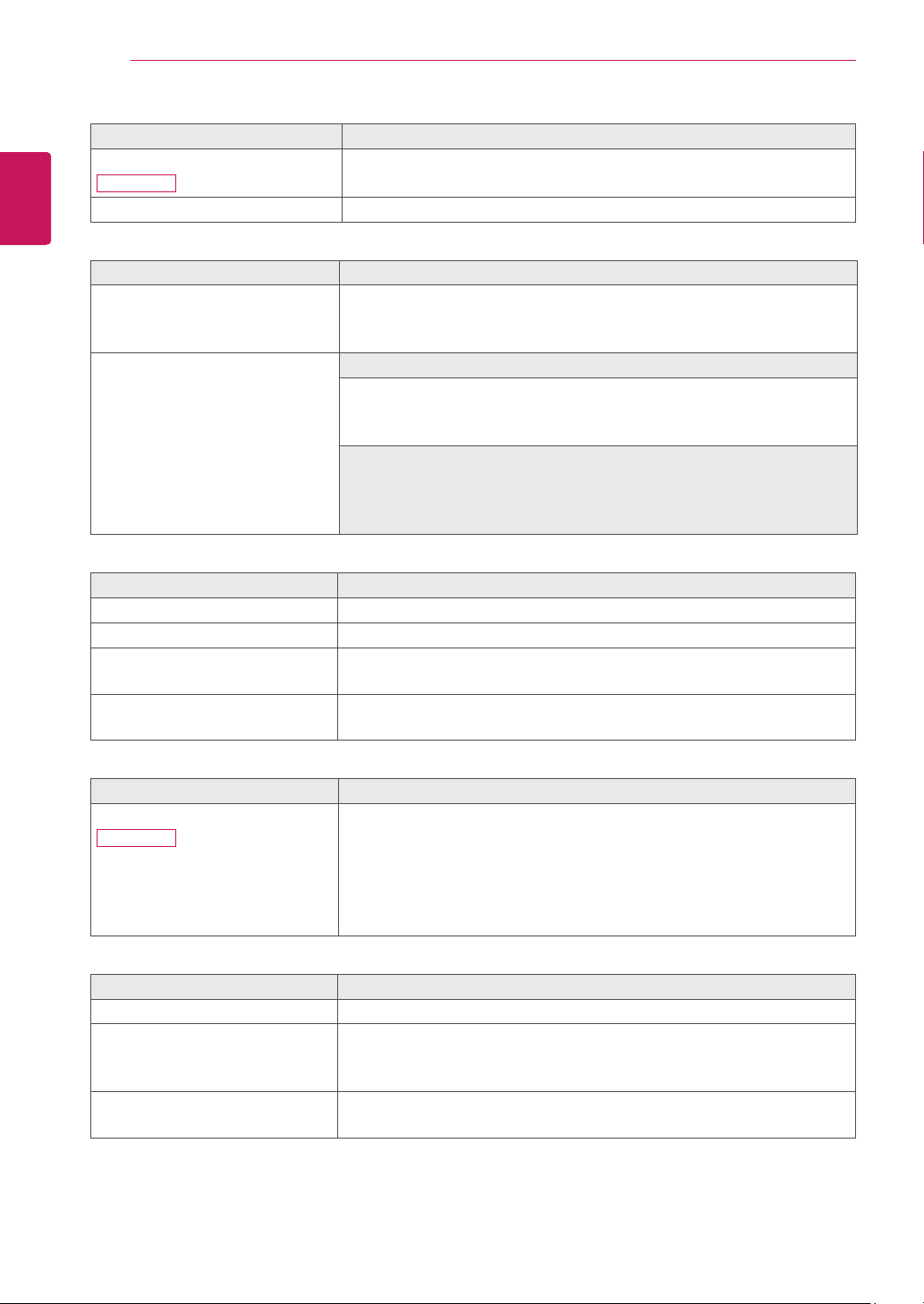
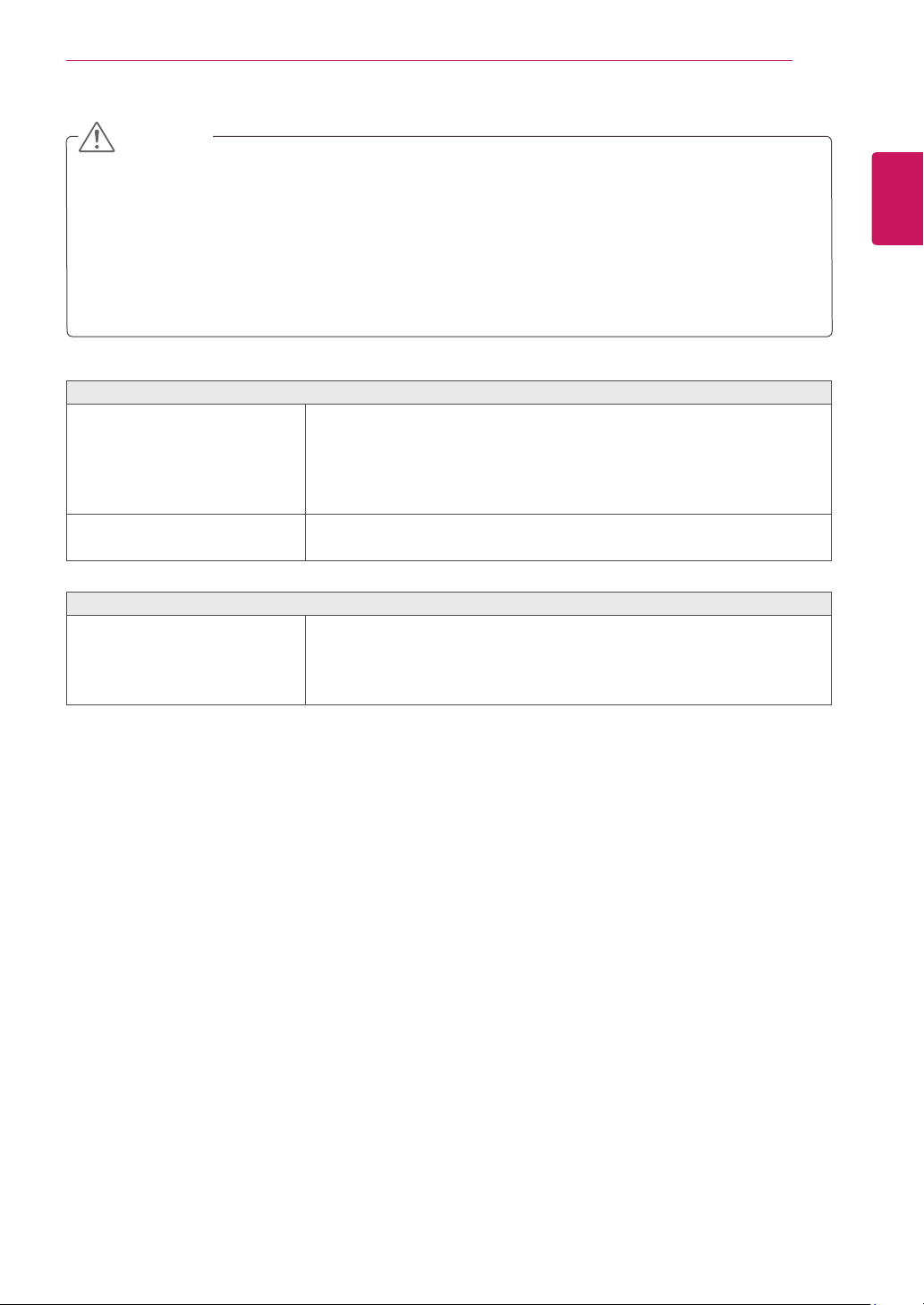
Menu > Next Menu > Picture
Description
Contrast
24MB34PY
Toadjustthecontrastofthescreen.
Sharpness Toadjusttheclearnessofthescreen.
Menu > Next Menu > Color
Description
Gamma Setyourowngammavalue.:Gamma0,Gamma1,Gamma2onthemonitor,
highgammavaluesdisplaywhitishimagesandlowgammavaluesdisplay
blackishimages.
Color Temp Custom
• Red: Setyourownredcolorlevels.
• Green: Setyourowngreencolorlevels.
• Blue: Setyourownbluecolorlevels.
Selectthescreencolor.
Warm: Setthescreentowarmcolortemperature(morered).
Medium:Setthescreentomediumcolortemperature.
Cool: Setthescreentocoolcolortemperature(moreblue).
Menu > Next Menu > Display
Description
Horizontal Tomoveimageleftandright.
Vertical Tomoveimageupanddown.
Clock Tominimizeanyverticalbarsorstripesvisibleonthescreenbackground.The
horizontalscreensizewillalsochange.
Phase Toadjustthefocusofthedisplay.Thisitemallowsyoutoremoveany
horizontalnoiseandclearorsharpentheimageofcharacters.
Menu > Next Menu > Audio
Description
Audio Input (OnlyinDPinput)
24MB34PY
ToSelecttheaudiosourcetooutputtospeakerfrombelowitems.
1.Audio-In:Theaudiosourceonexternalanalogaudiojack.
(OnlyinDsub/DVI-Dinput)
2.DP:TheaudiosourceonDPport.
3.Auto:TheaudiosourceisswitchedautomaticallybetweenDPorAudio-In.
DPhashigherpriority.(OnlyinDPinput)
Menu > Next Menu > Others
Description
Language Tochoosethelanguageinwhichthecontrolnamesaredisplayed.
Power Indicator Usethisfunctiontosetthepowerindicatoronthebottomsideofthemonitor
toOnorOff.IfyousetOff,itwillgooff.
IfyousetOnatanytime,thepowerindicatorwillautomaticallybeturnedon.
Off Time Setting Themonitorsetwillswitchtopoweroffmodeafterthetimetobechosenby
user(1~24hours)
19
CUSTOMIZING SETTINGS
ENGLISH
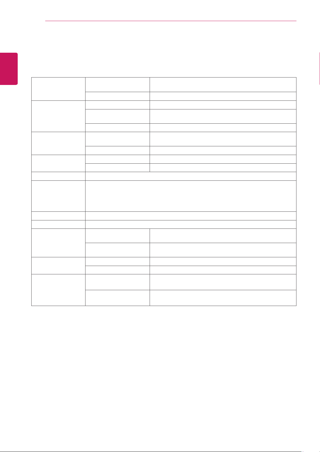
Reader Mode
Description
Reader 1 Itisamodethatthescreenisadjustedtothebestforthenewspaper.Ifyouwant
screenmorebright,youcancontrolbrightnessinMenuOSD.
Reader 2 Itisamodethatthescreenisadjustedtothebestforthecartoon.Ifyouwant
screenmorebright,youcancontrolbrightnessinMenuOSD.
Reader Off Itisamodethatreadermodeisoff.
NOTE
IfoptionofReaderModeisReader1orReader2,SMARTENERGYSAVINGwillautomaticallybeOff.
NOTE
SMART ENERGY SAVING
Description
High
EnablesSMARTENERGYSAVINGyoucansaveenergywiththisenergy-highefficient
function.
Low
EnablesSMARTENERGYSAVINGyoucansaveenergywiththisenergy-lowefficient
function.
Off DisablesSMARTENERGYSAVING.
*
SMART ENERGY SAVING:
Conserveenergybyusingluminancecompensationalgorithm.
SavingDatadependsonthePanel.So,thosevaluesshouldbedifferentfromeachpanelandpanelvendor.If
optionofSMARTENERGYSAVINGisHighorLow,monitorluminancebecomehigherorlowerdependonsource.
IfoptionofSMARTENERGYSAVINGisHighorLow,ReaderModewillautomaticallybeReaderOff.
20
TROUBLESHOOTING
ENGLISH
TROUBLESHOOTING
Check the following before calling for service.
No image appears
Isthepowercordofthedisplay
connected?
Checkandseeifthepowercordisconnectedproperlytothepoweroutlet.
Isthepowerindicatorlighton?
PressthePowerbutton.
Isthepoweronandthepowerindicator
White?
Adjustthebrightnessandthecontrast.
Isthepowerindicatorflickering?
Ifthedisplayisinpowersavingmode,trymovingthemouseorpressingany
keyonthekeyboardtobringupthescreen.
TrytoturnonthePC.
Doyouseean"OUTOFRANGE"
messageonthescreen?
ThismessageappearswhenthesignalfromthePC(videocard)isoutof
horizontalorverticalfrequencyrangeofthedisplay.Seethe'Specifications'
sectionofthismanualandconfigureyourdisplayagain.
Doyouseea"NOSIGNAL"messageon
thescreen?
Whenthemonitorison"No-Signal"in5minutes,themonitorgoestoDPM
mode.
Do you see a "OSD LOCKED" message on the screen?
Doyousee“OSDLOCKED”whenyou
pushMENUbutton?
Youcansecurethecurrentcontrolsettings,sothattheycannotbe
inadvertentlychanged.YoucanunlocktheOSDcontrolsatanytime
bypushingtheMENUbuttonforseveralseconds:themessage“OSD
UNLOCKED”willappear.
Display image is incorrect
DisplayPositionisincorrect.
PresstheAUTObuttontoautomaticallyadjustyourdisplayimagetothe
idealsetting.
Onthescreenbackground,vertical
barsorstripesarevisible.
PresstheAUTObuttontoautomaticallyadjustyourdisplayimagetothe
idealsetting.
Anyhorizontalnoiseappearinginany
imageorcharactersarenotclearly
portrayed.
PresstheAUTObuttontoautomaticallyadjustyourdisplayimagetothe
idealsetting.
CheckControl Panel
►
Display
►
Settingsandadjustthedisplaytothe
recommendedresolutionoradjustthedisplayimagetotheidealsetting.Set
thecolorsettinghigherthan24bits(truecolor).
21
TROUBLESHOOTING
ENGLISH
Display image is incorrect
Thescreencolorismonoorabnormal.
Checkifthesignalcableisproperlyconnectedanduseascrewdrivertofasten
ifnecessary.
Makesurethevideocardisproperlyinsertedintheslot.
Setthecolorsettinghigherthan24bits(truecolor)atControl Panel
►
Settings.
Thescreenblinks.
Checkifthescreenissettointerlacemodeandifyes,changeittothe
recommendresolution.
Do you see an "Unrecognized monitor, Plug&Play (VESA DDC) monitor found" message?
Haveyouinstalledthedisplaydriver?
BesuretoinstallthedisplaydriverfromthedisplaydriverCD(ordiskette)
thatcomeswithyourdisplay.Or,youcanalsodownloadthedriverfromour
website:http://www.lg.com.
MakesuretocheckifthevideocardsupportsPlug&Playfunction.
CheckControl Panel
►
Display
►
Settingsandseeifthefrequencyortheresolutionwerechanged.Ifyes,
readjustthevideocardtotherecommendresolution.
Iftherecommendedresolution(optimalresolution)isnotselected,lettersmaybeblurredandthescreenmaybe
dimmed,truncatedorbiased.Makesuretoselecttherecommendresolution.
ThesettingmethodcandifferbycomputerandO/S(OperationSystem),andresolutionmentionedabovemay
notbesupportedbythevideocardperformance.Inthiscase,pleaseasktothecomputerorthevideocard
manufacturer.
CAUTION
22
SPECIFICATIONS
ENGLISH
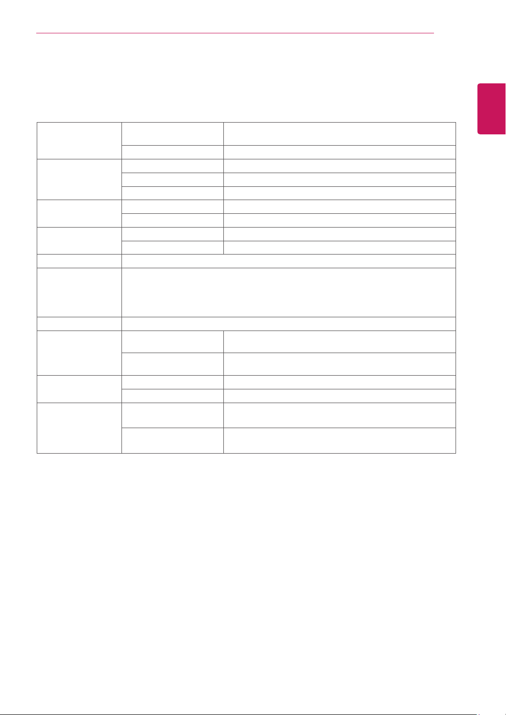
SPECIFICATIONS
Display Screen Type TFT(ThinFilmTransistor)LCD(LiquidCrystalDisplay)Panel,
Anti-Glarecoating
Pixel Pitch 0.2715mmx0.2715mm(PixelPitch)
Sync Input Horizontal Frequency 30kHzto83kHz(Automatic)
Vertical Frequency 56Hzto75Hz(D-SUB,DVI-D)
56Hzto61Hz(DP)
Input Form SeparateSync.Digital
Video Input Signal Input 15pinD-SUBConnector/DVI-DConnector(Digital)/
DPConnector
Input Form RGBAnalog(0.7Vp-p/75ohm),Digital
Resolution Max VESA1920x1080@60Hz
Recommend VESA1920x1080@60Hz
Plug & Play DDC2B(Analog,Digital,DP)
Power Consumption Onmode:16.7WTyp.(ENERGYSTAR®standard)*
24.9WTyp.(Outgoingcondition)**
SleepMode≤0.3W
OffMode≤0.3W
Power Input AC100-240V~50/60Hz1.2A
Speaker Wattage 1W+1W
Dimensions
(Width x Height x
Depth)
With Stand 569.1mmx381.8mmx239mm
(22.4inchesx15.0inchesx9.4inches)
Without Stand 569.1mmx341.9mmx63mm
(22.4inchesx13.5inchesx2.5inches)
Weight With Stand 4.75kg(10.5lbs)
Without Stand 3.45kg(7.6lbs)
Environmental
conditions
Operating Temperature
Operating Humidity
10°Cto35°C(50°Fto95°F)
10%to80%
Storage Temperature
Storage Humidity
-20°Cto60°C(-4°Fto140°F)
5%to90%non-Condensing
Thespecificationsaresubjecttochangewithoutnotice.
*Thepowerconsumptionlevelcanbedifferentbyoperatingconditionandmonitorsetting.
*TheOnmodepowerconsumptionismeasuredwithENERGYSTAR®teststandard.
**TheOnmodepowerconsumptionismeasuredwithLGEteststandard(FullWhitepattern,Maximumresolution).
24MB34PY
23
SPECIFICATIONS
ENGLISH
SPECIFICATIONS
Display Screen Type TFT(ThinFilmTransistor)LCD(LiquidCrystalDisplay)Panel,
Anti-Glarecoating
Pixel Pitch 0.2715mmx0.2715mm(PixelPitch)
Sync Input Horizontal Frequency 30kHzto83kHz(Automatic)
Vertical Frequency 56Hzto75Hz(D-SUB,DVI-D)
Input Form SeparateSync.Digital
Video Input Signal Input 15pinD-SUBConnector/DVI-DConnector(Digital)
Input Form RGBAnalog(0.7Vp-p/75ohm),Digital
Resolution Max VESA1920x1080@60Hz
Recommend VESA1920x1080@60Hz
Plug & Play DDC2B(Analog,Digital)
Power Consumption Onmode:16.7WTyp.(ENERGYSTAR®standard)*
21WTyp.(Outgoingcondition)**
SleepMode≤0.3W
OffMode≤0.3W
Power Input AC100-240V~50/60Hz1.2A
Dimensions
(Width x Height x
Depth)
With Stand 569.1mmx433mmx209.8mm
(22.4inchesx17.0inchesx8.3inches)
Without Stand 569.1mmx341.9mmx63mm
(22.4inchesx13.5inchesx2.5inches)
Weight With Stand 3.85kg(8.5lbs)
Without Stand 3.55kg(7.8lbs)
Environmental
conditions
Operating Temperature
Operating Humidity
10°Cto35°C(50°Fto95°F)
10%to80%
Storage Temperature
Storage Humidity
-20°Cto60°C(-4°Fto140°F)
5%to90%non-Condensing
Thespecificationsaresubjecttochangewithoutnotice.
*Thepowerconsumptionlevelcanbedifferentbyoperatingconditionandmonitorsetting.
*TheOnmodepowerconsumptionismeasuredwithENERGYSTAR®teststandard.
**TheOnmodepowerconsumptionismeasuredwithLGEteststandard(FullWhitepattern,Maximumresolution).
24MB34D
24
SPECIFICATIONS
ENGLISH
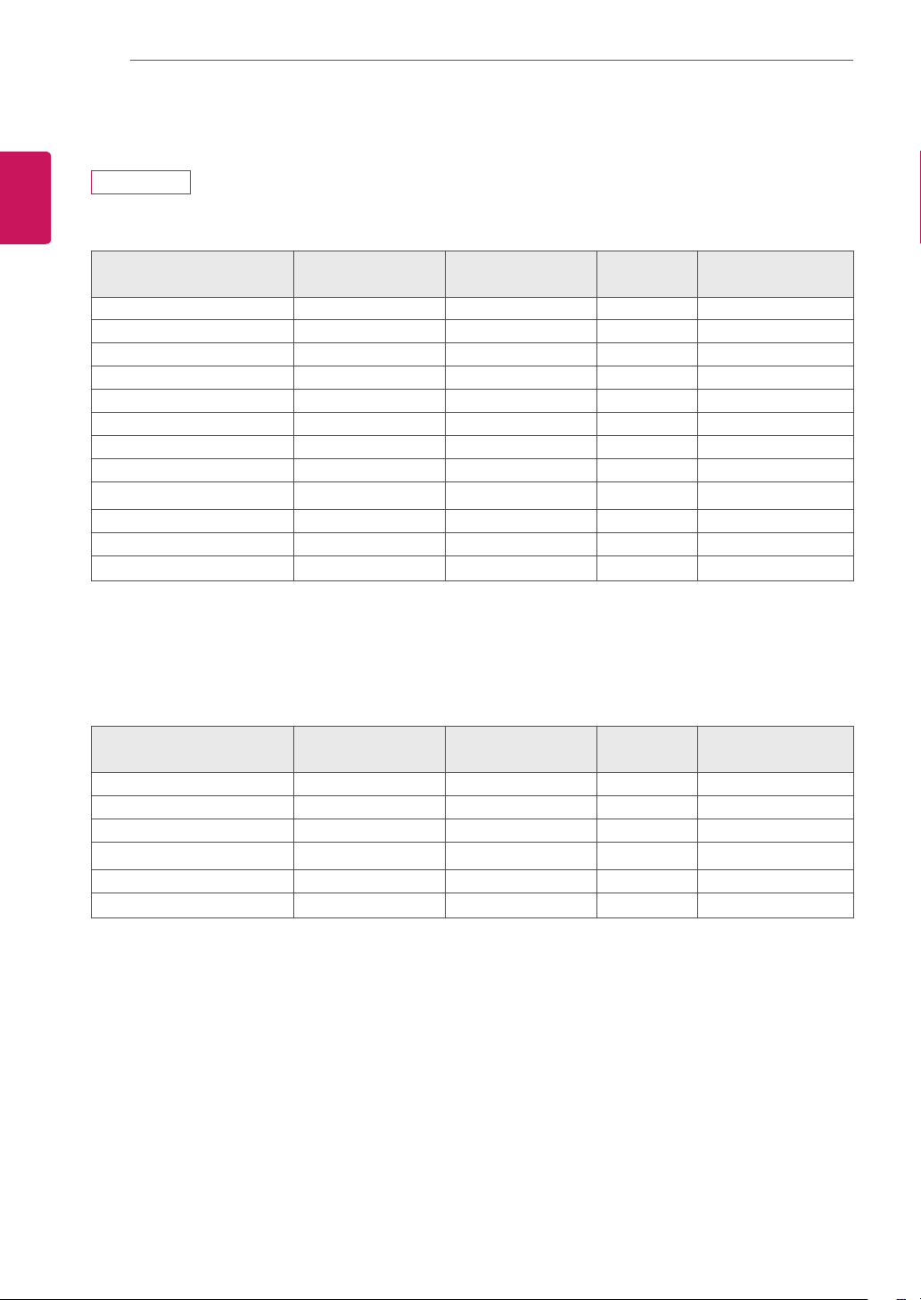
Preset Modes (Resolution)
24MB34PY
D-SUB/DVI Timing
Display Modes (Resolution)
Horizontal
Frequency (kHz)
Vertical Frequency
(Hz)
Polarity (H/
V)
720x400 31.468 70 -/+
640x480 31.469 60 -/-
640x480 37.500 75 -/-
800x600 37.879 60 +/+
800x600 46.875 75 +/+
1024x768 48.363 60 -/-
1024x768 60.023 75 +/+
1152x864 67.500 75 +/+
1280x1024 63.981 60 +/+
1280x1024 79.976 75 +/+
1680x1050 65.290 60 -/+
1920x1080 67.5 60 +/+
RecommendMode
DP Timing
Display Modes (Resolution)
Horizontal
Frequency (kHz)
Vertical Frequency
(Hz)
Polarity (H/
V)
640x480 31.469 60 -/-
800x600 37.879 60 +/+
1024x768 48.363 60 -/-
1280x1024 63.981 60 +/+
1680x1050 65.290 60 -/+
1920x1080 67.5 60 +/+
RecommendMode
25
SPECIFICATIONS
ENGLISH
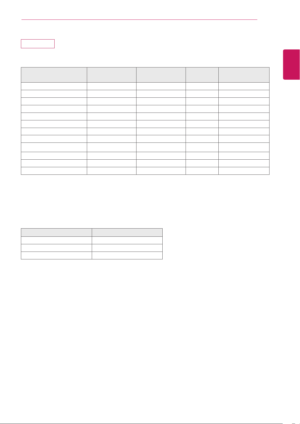
24MB34D
D-SUB/DVI Timing
Display Modes (Resolution)
Horizontal
Frequency(kHz)
Vertical
Frequency(Hz)
Polarity(H/
V)
720x400 31.468 70 -/+
640x480 31.469 60 -/-
640x480 37.500 75 -/-
800x600 37.879 60 +/+
800x600 46.875 75 +/+
1024x768 48.363 60 -/-
1024x768 60.023 75 +/+
1152x864 67.500 75 +/+
1280x1024 63.981 60 +/+
1280x1024 79.976 75 +/+
1680x1050 65.290 60 -/+
1920x1080 67.500 60 +/+ RecommendMode
Indicator
Mode LED Color
OnMode White
SleepMode BlinkingWhite
OffMode Off
MakesuretoreadtheSafetyPrecautionsbefore
usingtheproduct.
KeeptheOwner’sManual(CD)inanaccessibleplace
forfuturereference.
ThemodelandserialnumberoftheSETislocated
onthebackandonesideoftheSET.Recorditbelow
shouldyoueverneedservice.
AsanENERGYSTARPartnerLGEU.S.
A.,Inc.hasdeterminedthatthisproduct
meetstheENERGYSTARguidelinesfor
energyefficiency.
ENERGYSTARisasetofpower-saving
guidelinesissuedbytheU.S.Environmental
ProtectionAgency(EPA).
MODEL
SERIAL
*aboveinformationisonlyforUSAFCCRegulatory
Declaration of Conformity
TradeName:LG
Model:24MB34PY,24MB34D
ResponsibleParty:LGElectronicsInc.
Address:1000SylvanAve.EnglewoodCliffs
NJ07632U.S.A
TEL:201-266-2534