Loading ...
Loading ...
Loading ...
10
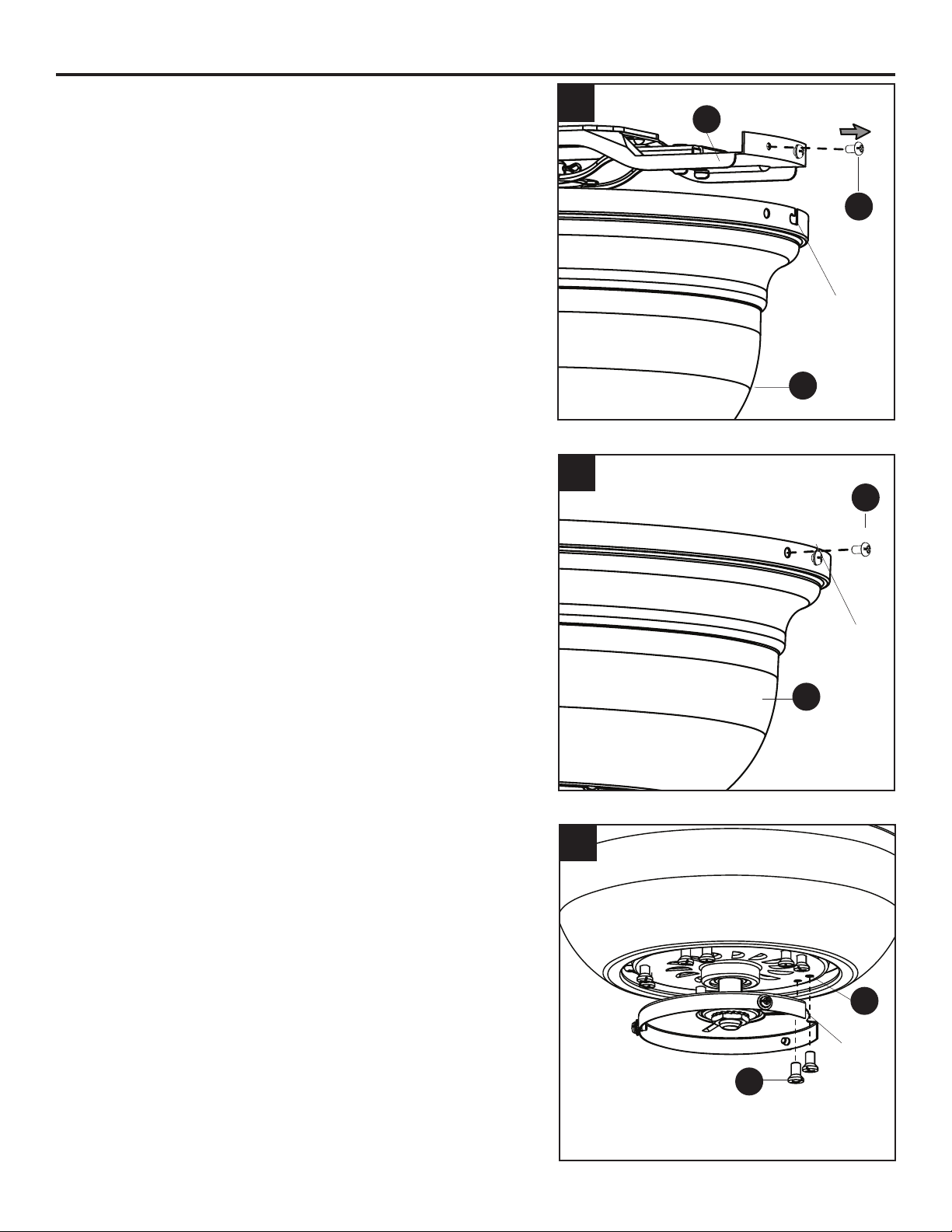
FINAL INSTALLATION
1. Temporarily lift the motor housing (A) to the upper
mounting bracket (B) to determine which two motor
housing screws (O) in the sides of the upper mounting
bracket (B) align with the slotted holes in the top edge
of the motor housing (A). Partially loosen the two motor
housing screws (O) that align with the slotted holes.
Remove the other two motor housing screws (O) from
the upper mounting bracket (B).
2. Slide the motor housing (A) over the motor (E),
aligning the slotted holes in the motor housing (A) with
the loosened motor housing screws (O) in the upper
mounting bracket (B). Twist the motor housing (A)
clockwise to lock. Then re-insert the two previously
removed motor housing screws (O) and securely
tighten all screws.
3. Remove the 10 motor screws (L) from the motor (E)
and save for later use.
Note:ThenotchinthetterplateallowsaPhillips
screwdriver (not included) access to motor screws (L).
3
1
2
A
L
E
B
O
A
Slotted
Hole
Notch
Slotted
Hole
O
Loading ...
Loading ...
Loading ...