Loading ...
Loading ...
Loading ...
4
ENGLISH
The foundation must be level even
Outside unit foundation work
Avoid short circuits and ensure
sufficient space is allowed for service
Installation of outside unit
Refer to automatic addressing flowchart
Automatic addressing of indoor unit
In the final check for 24hours at 3.8 MPa(38.7 kgf/cm
2
) there
must be no drop in pressure.
Airtight test
Multiple core cable must not be used.
(suitable cable should be selected)
Electrical work
(connection circuits and drive circuits)
Make sure no gaps are left where
the insulating materials are joined
Heat insulation work
Make sure airflow is sufficient
Duct work
Adjust to downward gradient
Drain pipe work
Special attention to dryness,
cleanness and tightness
Refrigerant piping work
Check model name to
make sure the fitting
is made correctly
Installation of indoor unit
Take account of gradient
of drain piping
Sleeve and insert work
Make connection clearly between outside, indoor,
remote controller and option.
Preparation of contract drawings
Indicate clearly who will be responsible for switch setting.
Determination of division work
The vacuum pump used must have a capacity of reaching at least
5 torr, more than 1 hour
Vacuum drying
Recharge correctly as calculated in this manual. and record the
amount of added refrigerant
Additional charge of refrigerant
Make sure there are no gaps left between the facing materials
used on the ceiling
Fit facing panels
Run each indoor unit in turn to make sure the pipe work
has been fitted correctly
Test run adjustment
Explain the use of the system as clearly as possible to your customer and
make sure all relevant documentation is in order
Transfer to customer with explanation
Preheat the crank case with the electrical heater for more than 6 hours.
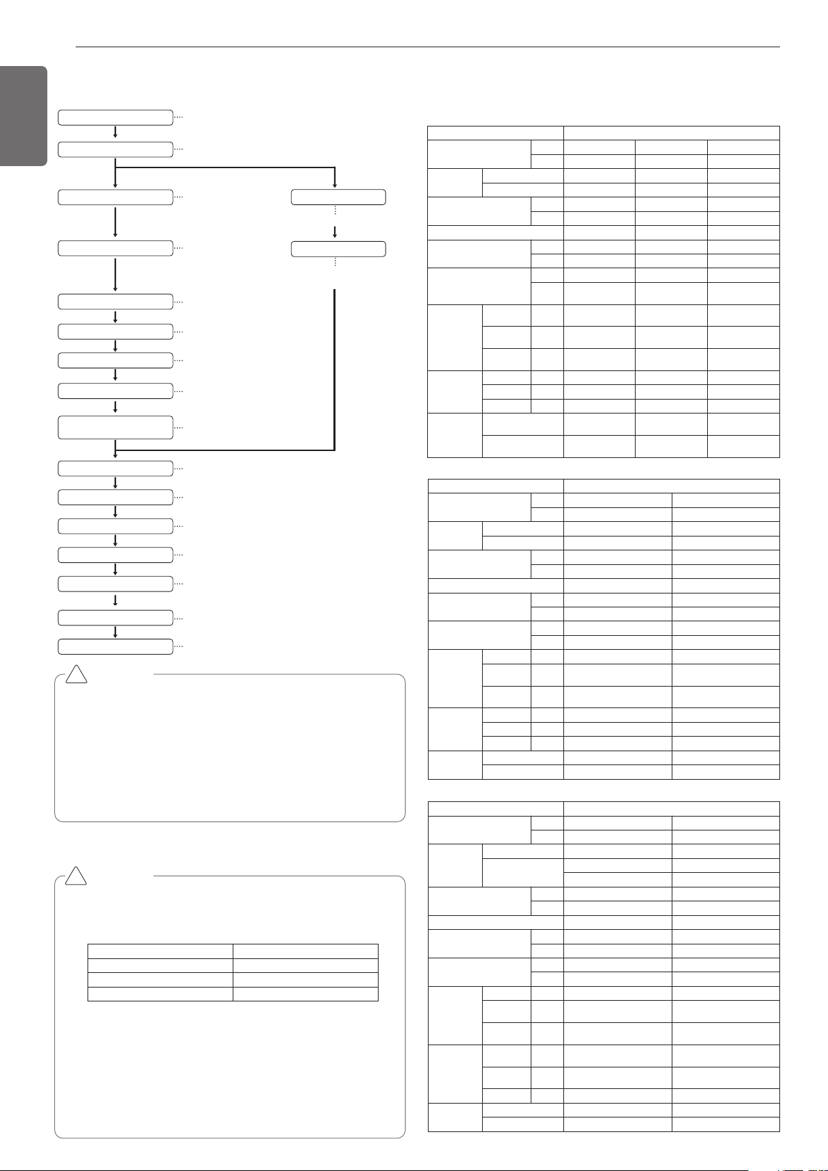
CAUTION
• The above list indicates the order in which the individual work opera-
tions are normally carried out but this order may be varied where
local conditions warrants such change.
• The thickness of the piping should comply with the relevant local and
national regulations for the designed pressure 3.8Mpa(551.1psi).
• Since R410A is a mixed refrigerant, the required additional
refrigerant must be charged in its liquid state.(If the refrigerant is
charged in its gaseous state, its composition changes and the sys-
tem will not work properly.)
!
CAUTION
Notes: *
We can guarantee the operation only within 130% Combina-
tion. If you want to connect more than 130% combination,
please contact us and discuss the requirement like below.
• If the operation of indoor unit is more than 130%, low airflow
operation is recommended in all the indoor units.
• If the operation of indoor unit is more than 130%, additional re-
frigerant is needed according to the Aheadquarter guidance.
• Over 130%, capacity is same as capacity of 130%, Same re-
mark is valid for power input.
•
Ratio of the running Indoor Units to the Outside: Within 10 ~ 100%
•
A combination operation over 100% cause to reduce each indoor unit capacity.
Combination Ratio(50~200%)
Outside Unit Number Connection Ratio
Single outside unit s 200%
Double outside unit s 160%
More than Triple outside unit s
130%
!
OUTSIDE UNITS INFORMATION
INSTALLATION PROCESS
Power Supply : 3Ø, 460V, 60Hz
Model Name : ARWB***DAS4
Unit
1 Unit
System Capacity
HP 8 10 12
TON 6 8 10
Model
Combination Unit ARWB072DAS4 ARWB096DAS4 ARWB121DAS4
Independent Unit ARWB072DAS4 ARWB096DAS4 ARWB121DAS4
Refrigerant Precharged Amount
kg
5.8 5.8 5.8
lbs
12.8 12.8 12.8
Maximum Connectable Number of Indoor Units
13 16 20
Net Weight
kg
127 x 1 127 x 1 127 x 1
lbs
280 x 1 280 x 1 280 x 1
Dimensions(WxHxD)
mm
755 × 997 × 500 755 × 997 × 500 755 × 997 × 500
inch
(29-23/32 x 39-1/4 x
19-11/16) x 1
(29-23/32 x 39-1/4 x
19-11/16) x 1
(29-23/32 x 39-1/4 x
19-11/16) x 1
Refrigerant
Connecting
Pipes
Liquid Pipes mm(inch)
9.52(3/8) 9.52(3/8) 12.7(1/2)
Low Pressure
Gas Pipes
mm(inch)
22.7(7/8) 22.7(7/8) 25.4(1)
High Pressure
Gas Pipes
mm(inch)
19.05(3/4) 19.05(3/4) 19.05(3/4)
Water
Connecting
Pipes
Inlet mm(inch)
PT40(1-1/2)(Internal thread) PT40(1-1/2)(Internal thread) PT40(1-1/2)(Internal thread)
Outlet mm(inch)
PT40(1-1/2)(Internal thread) PT40(1-1/2)(Internal thread) PT40(1-1/2)(Internal thread)
Drain Outlet mm(inch)
PT20(3/4)(external thread) PT20(3/4)(external thread) PT20(3/4)(external thread)
Temp. range of
Circulation water
Cooling
10°C ~ 45°C
(50°F ~ 113°F)
10°C ~ 45°C
(50°F ~ 113°F)
10°C ~ 45°C
(50°F ~ 113°F)
Heating
-5°C ~ 45°C
(23°F ~ 113°F)
-5°C ~ 45°C
(23°F ~ 113°F)
-5°C ~ 45°C
(23°F ~ 113°F)
Unit 1 Unit
System Capacity
HP 14 18
TON 12 14
Model
Combination Unit ARWB144DAS4 ARWB168DAS4
Independent Unit ARWB144DAS4 ARWB168DAS4
Refrigerant Precharged Amount
kg 3 3
lbs 6.6 6.6
Maximum Connectable Number of Indoor Units
23 29
Net Weight
kg 140 x 1 140 x 1
lbs 309 x 1 309 x 1
Dimensions(WxHxD)
mm 755 × 997 × 500 755 × 997 × 500
inch (29-23/32 x 39-1/4 x 19-11/16) x 1 (29-23/32 x 39-1/4 x 19-11/16) x 1
Refrigerant
Connecting
Pipes
Liquid Pipes mm(inch) 12.7(1/2) 12.7(1/2)
Low Pressure
Gas Pipes
mm(inch) 28.58(1-1/8) 28.58(1-1/8)
High Pressure
Gas Pipes
mm(inch) 19.05(3/4) 19.05(3/4)
Water
Connecting
Pipes
Inlet mm(inch) PT40(1-1/2)(Internal thread) PT40(1-1/2)(Internal thread)
Outlet mm(inch) PT40(1-1/2)(Internal thread) PT40(1-1/2)(Internal thread)
Drain Outlet mm(inch) PT20(3/4)(external thread) PT20(3/4)(external thread)
Temp. range of
Circulation water
Cooling 10°C ~ 45°C(50°F ~ 113°F) 10°C ~ 45°C(50°F ~ 113°F)
Heating -5°C ~ 45°C(23°F ~ 113°F) -5°C ~ 45°C(23°F ~ 113°F)
Unit 1 Unit / 2 Unit
System Capacity
HP 20 24
TON 16 20
Model
Combination Unit ARWB192DAS4 ARWB240DAS4
Independent Unit
ARWB192DAS4 ARWB144DAS4
ARWB096DAS4
Refrigerant Precharged Amount
kg 3 3.0+5.8
lbs 6.6 6.6+12.8
Maximum Connectable Number of Indoor Units
32 39
Net Weight
kg 140 x 1 (140 x 1) + (127 x 1)
lbs 309 x 1 (309 x 1) + (280 x 1)
Dimensions(WxHxD)
mm 755 × 997 × 500 (755 × 997 × 500) x 2
inch (29-23/32 x 39-1/4 x 19-11/16) x 1 (29-23/32 x 39-1/4 x 19-11/16) x 2
Refrigerant
Connecting
Pipes
Liquid Pipes mm(inch) 12.7(1/2) 19.05(3/4)
Low Pressure
Gas Pipes
mm(inch) 28.58(1-1/8) 34.9(1-3/8)
High Pressure
Gas Pipes
mm(inch) 19.05(3/4) 28.58(1-1/8)
Water
Connecting
Pipes
Inlet mm(inch) PT40(1-1/2)(Internal thread) PT40(1-1/2)(Internal thread)
Outlet mm(inch) PT40(1-1/2)(Internal thread) PT40(1-1/2)(Internal thread)
Drain Outlet mm(inch) PT20(3/4)(external thread) PT20(3/4)(external thread)
Temp. range of
Circulation water
Cooling 10°C ~ 45°C(50°F ~ 113°F) 10°C ~ 45°C(50°F ~ 113°F)
Heating -5°C ~ 45°C(23°F ~ 113°F) -5°C ~ 45°C(23°F ~ 113°F)
Loading ...
Loading ...
Loading ...