
Loading ...
Loading ...
Loading ...
11
ENGLISH
Opening shutoff valve
1 Remove the cap and turn the valve counter clockwise with the
wrench.
2 Turn it until the shaft stops.
Do not apply excessive force to the shutoff valve. Doing so may
break the valve body, as the valve is not a backseat type. Always
use the special tool.
3 Make sure to tighten the cap securely.
Heat insulation
1 Use the heat insulation material for the refrigerant piping which has
an excellent heat-resistance (over 248°F).
2 Precautions in high humidity circumstance:
This air conditioner has been tested according to the "ISO Condi-
tions with Mist" and confirmed that there is not any default. How-
ever, if it is operated for a long time in high humid atmosphere
(dew point temperature: more than 73.4°F), water drops are liable
to fall. In this case, add heat insulation material according to the fol-
lowing procedure:
- Heat insulation material to be prepared... EPDM (Ethylene Propy-
lene Diene Methylene)-over 248°F the heat-resistance tempera-
ture.
- Add the insulation over 10mm(0.39 inch) thickness at high humid-
ity environment.
Indoor unit
Thermal insulator
(accessory)
Fastening band
(accessory)
Refrigerant piping
Closing shutoff valve
1 Remove the cap and turn the valve clockwise with the wrench.
2 Securely tighten the valve until the shaft contacts the main body seal.
3 Make sure to tighten the cap securely.
* For the tightening torque, refer to the table on the below.
Tightening torque
Plumbing materials and storage methods
Pipe must be able to obtain the specified thickness and should be
used with low impurities.
Also when handling storage, pipe must be careful to prevent a frac-
ture, deformity and wound.
Should not be mixed with contaminations such as dust, moisture.
Shut off
valve size
[mm(inch)]
Tightening torque N·m(lbs ·ft)(Turn clockwise to close)
Shaft(valve body)
Cap
(Valve lid)
Service
port
Flare nut
Gas line pip-
ing attached
to unit
Closed Opened
Hexagonal
wrench
Ø6.35
(1/4)
6.0 ±0.6
(4.4±0.4)
5.0 ±0.0
(3.7±0.4)
4mm
(0.16inch)
17.6±2.0
(13.0±1.5)
12.7±2
(9.4±1.5)
16±2
(12±1.5)
-
Ø9.52
(3/8)
38±4
(28±3.0)
Ø12.7
(1/2)
10.0 ±1.0
(7.4±0.7)
20.0±2.0
(14.8±1.5)
55±6(
41±4.4)
Ø15.88
(5/8)
12.0 ±1.2
(8.9±0.9)
5mm
(0.24inch)
25.0±2.5
(18.4±1.8)
75±7
(55±5.1)
Ø19.05
(3/4)
14.0 ±1.4
(10.3±1.0)
110±10
(81.1±7.4)
Ø22.2
(7/8)
30.0 ±3.0
(22.1±2.2)
8mm
(0.31inch)
-
25±3.0
(18.5±2.2)
Ø25.4
(1.0)
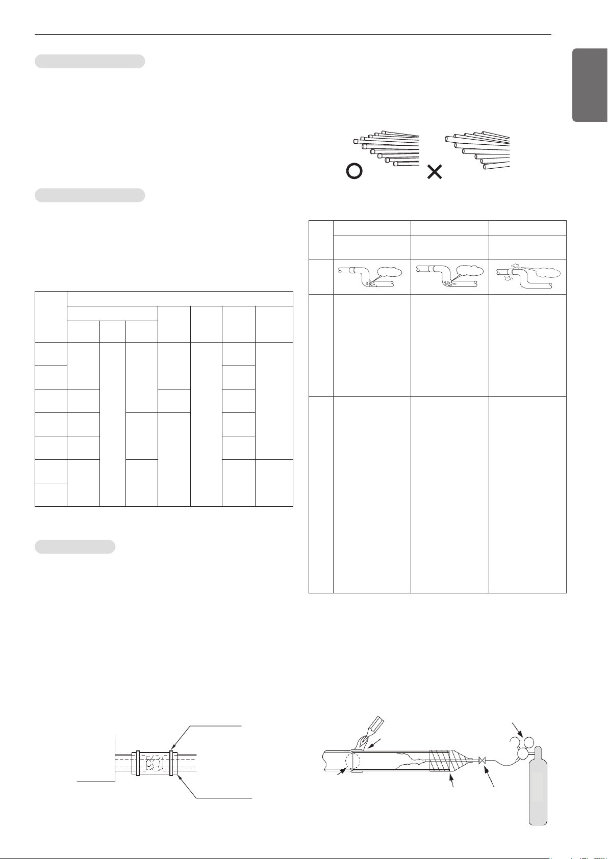
Refrigerant piping on three principles
Drying Cleanliness Airtight
Should be no moisture
inside
No dust inside.
There is no refrigerant
leakage
Items
Moisture
Dust
Leakage
Cause
failure
- Significant hydroly-
sis of refrigerant oil
- Degradation of re-
frigerant oil
- Poor insula’tion of
the compressor
- Do not cold and
warm
- Clogging of EEV,
Capillary
- Degradation of re-
frigerant oil
- Poor insulation of
the compressor
- Do not cold and
warm
- Clogging of EEV,
Capillary
- Gas shortages
- Degradation of re-
frigerant oil
- Poor insulation of
the compressor
- Do not cold and
warm
Coun-
termea-
sure
-
No moisture in the pipe
- Until the connec-
tion is completed,
the plumbing pipe
entrance should be
strictly controlled.
- Stop plumbing at
rainy day.
- Pipe entrance
should be taken
side or bottom.
-
When removal burr
after cutting pipe, pipe
entrance should be
taken down.
- Pipe entrance
should be fitted cap
when pass through
the walls.
- No dust in the pipe.
- Until the connec-
tion is completed,
the plumbing pipe
entrance should be
strictly controlled.
- Pipe entrance
should be taken
side or bottom.
- When removal burr
after cutting pipe,
pipe entrance
should be taken
down.
- Pipe entrance
should be fitted cap
when pass through
the walls.
- Airtightness test
should be.
- Brazing operations
to comply with
standards.
- Flare to comply
with standards.
- Flange connections
to comply with
standards.
Nitrogen substitution method
Welding, as when heating without nitrogen substitution a large
amount of the oxide film is formed on the internal piping.
The oxide film is a caused by clogging EEV, Capillary, oil hole of accu-
mulator and suction hole of oil pump in compressor.
It prevents normal operation of the compressor.
In order to avoid this problem, Welding should be done after replacing
air by nitrogen gas.
When welding plumbing pipe, the work is required.
Regulator
Nitrogen gas Pressure
0.02Mpa (2.9psi) less
Auxiliary valve
Taping
(Should not
contain air)
Welding Point
Note) should not block the outlet side.
When the internal pressure in pipe is abo
ve the atmospheric pressure, pinhole is o
ccurred and it is a leakage cause.
Oxide scale
Nitrogen
Loading ...
Loading ...
Loading ...