

MINI
Owner's Manual for Vehicle
Thank you for choosing a MINI.
The more familiar you are with your vehicle, the better control
you will have on the road. We therefore strongly suggest:
Read this Owner's Manual before starting off in your new MINI. It
contains important information on vehicle operation that will
help you make full use of the technical features available in your
MINI. The manual also contains information designed to en‐
hance operating reliability and road safety, and to contribute to
maintaining the value of your MINI.
Any updates made after the editorial deadline can be found in
the appendix of the printed Owner's Handbook for Vehicle.
Get started now. We wish you driving fun and inspiration with
your MINI
The MINI team
Online Edition for Part no. 01 40 2 963 307 - VI/15

© 2015 Bayerische Motoren Werke
Aktiengesellschaft
Munich, Germany
Reprinting, including excerpts, only with the written
consent of BMW AG, Munich.
US English VI/15, 07 15 490
Printed on environmentally friendly paper, bleached
without chlorine, suitable for recycling.
Online Edition for Part no. 01 40 2 963 307 - VI/15

Contents
The fastest way to find information on a partic‐
ular topic or item is by using the index, refer to
page 242.
6 Information
AT A GLANCE
14 Cockpit
18 Radio
CONTROLS
22 Opening and closing
36 Adjusting
45 Transporting children safely
49 Driving
62 Displays
76 Lights
81 Safety
97 Driving stability control systems
101 Driving comfort
115 Climate control
121 Interior equipment
123 Digital compass
129 Storage compartments
DRIVING TIPS
136 Things to remember when driving
139 Loading
142 Saving fuel
ENTERTAINMENT
150 Tone
151 Radio
156 Multimedia
COMMUNICATION
164 Bluetooth hands-free system
MOBILITY
174 Refueling
176 Fuel
178 Wheels and tires
193 Engine compartment
195 Engine oil
198 Coolant
200 Maintenance
202 Replacing components
214 Breakdown assistance
220 Care
REFERENCE
226 Technical data
231 Appendix
235 License Texts and Certifications
242 Everything from A to Z
Online Edition for Part no. 01 40 2 963 307 - VI/15

Information
Using this Owner's
Manual
The fastest way to find information on a partic‐
ular topic is by using the index.
An initial overview of the vehicle is provided in
the first chapter.
Updates made after the editorial
deadline
Any updates made after the editorial deadline
can be found in the appendix of the printed
Owner's Handbook for Vehicle.
Additional sources of information
A dealer’s service center or another qualified
service center or repair shop will be glad to an‐
swer additional questions at any time.
Information about MINI, e.g., on technology, is
available on the Internet: www.miniusa.com
Symbols and displays
Symbols in the Owner's Manual
Indicates precautions that must be followed
precisely in order to avoid the possibility of
personal injury and serious damage to the
vehicle.
◄ Marks the end of a specific item of
information.
"..." Identifies radio display texts used to select
individual functions.
Refers to measures that can be taken to
help protect the environment.
Action steps
Action steps to be carried out are presented as
numbered list. The steps must be carried out in
the defined order.
1. First action step.
2. Second action step.
Enumerations
Enumerations without mandatory order or al‐
ternative possibilities are presented as list with
bullet points.
▷ First possibility.
▷ Second possibility.
Symbols on vehicle components
Indicates that you should consult the
relevant section of this Owner's Manual for
information on a particular part or assembly.
Vehicle features and op‐
tions
This Owner's Manual describes all models and
all standard, country-specific and optional
equipment that is offered in the model series.
Therefore, in this Owner's Manual, we also de‐
scribe and illustrate features that are not avail‐
able in your vehicle, e.g., because of the se‐
lected optional features or the country-specific
version.
This also applies to safety-related functions and
systems.
The respectively applicable country provisions
must be observed when using the respective
features and systems.
For any options and equipment not described
in this Owner's Handbook, refer to the Supple‐
mentary Owner's Handbooks.
Seite 6
Information
6
Online Edition for Part no. 01 40 2 963 307 - VI/15

On right-hand drive vehicles, some controls are
arranged differently from what is shown in the
illustrations.
Status of the Owner's
Manual
Basic information
The manufacturer of your vehicle pursues a
policy of constant development that is con‐
ceived to ensure that our vehicles continue to
embody the highest quality and safety stan‐
dards. In rare cases, therefore, the features de‐
scribed in this Owner's Manual may differ from
those in your vehicle.
Updates made after the editorial
deadline
Any updates made after the editorial deadline
can be found in the appendix of the printed
Owner's Handbook for Vehicle.
Own safety
Manufacturer
The manufacturer of this MINI is Bayerische
Motoren Werke Aktionengesellschaft, BMW AG.
Warranty
Your vehicle is technically configured for the
operating conditions and registration require‐
ments applying in the country of first delivery
also known as homologation. If your vehicle is
to be operated in a different country it might
be necessary to adapt your vehicle to poten‐
tially differing operating conditions and permit
requirements. If your vehicle does not comply
with the homologation requirements in a cer‐
tain country you may not be able to lodge war‐
ranty claims for your vehicle there. Further in‐
formation on warranty is available from a
dealer’s service center.
Maintenance and repairs
Advanced technology, e.g., the use of modern
materials and high-performance electronics,
requires suitable maintenance and repair work.
The manufacturer of your vehicle recommends
that you entrust corresponding procedures to a
MINI dealer’s service center.
If you choose to use another service facility, the
manufacturer of your vehicle recommends use
of a facility that performs work, e.g. mainte‐
nance and repair, according to MINI specifica‐
tions with properly trained personnel, referred
to in this Owner's Manual as "another qualified
service center or repair shop".
If work is performed improperly, e.g. mainte‐
nance and repair, there is a risk of subsequent
damage and related safety risks.
Parts and accessories
The manufacturer of your vehicle recommends
the use of parts and accessory products ap‐
proved by the manufacturer of the MINI.
Approved parts and accessories, and advice on
their use and installation are available from a
MINI dealer's service center.
MINI parts and accessories were tested by the
manufacturer of the MINI for their safety and
suitability in MINI vehicles.
The manufacturer of your vehicle warrants gen‐
uine MINI parts and accessories.
The manufacturer of your vehicle does not
evaluate whether each individual product from
another manufacturer can be used with MINI
vehicles without presenting a safety hazard,
even if a country-specific official approval was
issued. The manufacturer of your vehicle does
not evaluate whether these products are suita‐
ble for MINI vehicles under all usage conditions.
California Proposition 65 Warning
California laws require us to state the following
warning:
Seite 7
Information
7
Online Edition for Part no. 01 40 2 963 307 - VI/15

Engine exhaust and a wide variety of automo‐
bile components and parts, including compo‐
nents found in the interior furnishings in a vehi‐
cle, contain or emit chemicals known to the
State of California to cause cancer and birth de‐
fects and reproductive harm. In addition, cer‐
tain fluids contained in vehicles and certain
products of component wear contain or emit
chemicals known to the State of California to
cause cancer and birth defects or other repro‐
ductive harm. Battery posts, terminals and re‐
lated accessories contain lead and lead com‐
pounds. Wash your hands after handling. Used
engine oil contains chemicals that have caused
cancer in laboratory animals. Always protect
your skin by washing thoroughly with soap and
water.
Service and warranty
We recommend that you read this publication
thoroughly. Your vehicle is covered by the fol‐
lowing warranties:
▷ New Vehicle Limited Warranty.
▷ Rust Perforation Limited Warranty.
▷ Federal Emissions System Defect Warranty.
▷ Federal Emissions Performance Warranty.
▷ California Emission Control System Limited
Warranty.
Detailed information about these warranties is
listed in the Service and Warranty Information
Booklet for US models or in the Warranty and
Service Guide Booklet for Canadian models.
Your vehicle has been specifically adapted and
designed to meet the particular operating con‐
ditions and homologation requirements in your
country and continental region in order to de‐
liver the full driving pleasure while the vehicle is
operated under those conditions. If you wish to
operate your vehicle in another country or re‐
gion, you may be required to adapt your vehi‐
cle to meet different prevailing operating con‐
ditions and homologation requirements. You
should also be aware of any applicable war‐
ranty limitations or exclusions for such country
or region. In such case, please contact Cus‐
tomer Relations for further information.
Maintenance
Maintain the vehicle regularly to sustain the
road safety, operational reliability and the New
Vehicle Limited Warranty.
Specifications for required maintenance meas‐
ures:
▷ MINI Maintenance system
▷ Service and Warranty Information Booklet
for US models
▷ Warranty and Service Guide Booklet for
Canadian models
If the vehicle is not maintained according to
these specifications, this could result in serious
damage to the vehicle. Such damage is not
covered by the MINI New Vehicle Limited War‐
ranty.
Data memory
Many electronic components on your vehicle
are equipped with data memories that tempo‐
rarily or permanently store technical informa‐
tion about the condition of the vehicle, events
and faults. This technical information generally
records the state of a component, a module, a
system or the environment:
▷ Operating mode of system components, fill
levels for instance.
▷ Status messages for the vehicle and from its
individual components, e.g., wheel rotation
speed/vehicle speed, deceleration, trans‐
verse acceleration.
▷ Malfunctions and faults in important system
components, e.g., lights and brakes.
▷ Responses by the vehicle to special situa‐
tions such as airbag deployment or engag‐
ing the stability control system.
▷ Ambient conditions, such as temperature.
Seite 8
Information
8
Online Edition for Part no. 01 40 2 963 307 - VI/15
This data is purely technical in nature and is
used to detect and correct faults and to opti‐
mize vehicle functions. Motion profiles over
routes traveled cannot be created from this
data. When service offerings are used, e.g., re‐
pair services, service processes, warranty
claims, quality assurance, this technical infor‐
mation can be read out from the event and
fault memories by employees of the dealer’s
service center or another qualified service cen‐
ter or repair shop, including the manufacturer,
using special diagnostic tools. You can obtain
further information there if you need it. After
an error is corrected, the information in the
fault memory is deleted or overwritten on a
continuous basis.
With the vehicle in use there are situations
where you can associate these technical data
with individuals if combined with other infor‐
mation, e.g., an accident report, damage to the
vehicle, eye witness accounts — possibly with
the assistance of an expert.
Additional functions that are contractually
agreed with the customer - such as vehicle
emergency locating - you can transmit certain
vehicle data from the vehicle.
Event Data Recorder EDR
This vehicle is equipped with an event data re‐
corder EDR. The main purpose of an EDR is to
record, in certain crash or near crash-like situa‐
tions, such as an air bag deployment or hitting
a road obstacle, data that will assist in under‐
standing how a vehicle’s systems performed.
The EDR is designed to record data related to
vehicle dynamics and safety systems for a short
period of time, typically 30 seconds or less.
The EDR in this vehicle is designed to record
such data as:
▷ How various systems in your vehicle were
operating.
▷ Whether or not the driver and passenger
safety belts were fastened.
▷ How far, if at all, the driver was depressing
the accelerator and/or brake pedal.
▷ How fast the vehicle was traveling.
These data can help provide a better under‐
standing of the circumstances in which crashes
and injuries occur.
EDR data are recorded by your vehicle only if a
nontrivial crash situation occurs; no data are re‐
corded by the EDR under normal driving condi‐
tions and no personal data, e.g., name, gender,
age, and crash location, are recorded.
However, other parties, such as law enforce‐
ment, could combine the EDR data with the
type of personally identifying data routinely ac‐
quired during a crash investigation.
To read data recorded by an EDR, special
equipment is required, and access to the vehi‐
cle or the EDR is needed. In addition to the ve‐
hicle manufacturer, other parties, such as law
enforcement, that have the special equipment,
can read the information if they have access to
the vehicle or the EDR.
Vehicle identification
number
The vehicle identification number can be found
in the engine compartment.
The vehicle identification number can also be
found behind the windshield.
Seite 9
Information
9
Online Edition for Part no. 01 40 2 963 307 - VI/15

Reporting safety defects
For US customers
The following only applies to vehicles owned
and operated in the US.
If you believe that your vehicle has a defect
which could cause a crash or could cause injury
or death, you should immediately inform the
National Highway Traffic Safety Administration
NHTSA, in addition to notifying MINI of North
America, LLC, P.O. Box 1227, Westwood, New
Jersey 07675-1227, Telephone
1-800-831-1117.
If NHTSA receives similar complaints, it may
open an investigation, and if it finds that a
safety defect exists in a group of vehicles, it
may order a recall and remedy campaign.
However, NHTSA cannot become involved in
individual problems between you, your dealer,
or MINI of North America, LLC.
To contact NHTSA, you may call the Vehicle
Safety Hotline toll-free at 1-888-327-4236
(TTY: 1-800-424-9153); go to http://www.safe‐
rcar.gov; or write to: Administrator, NHTSA, 400
Seventh Street, SW., Washington, DC 20590.
You can also obtain other information about
motor vehicle safety from http://www.safe‐
rcar.gov
For Canadian customers
Canadian customers who wish to report a
safety-related defect to Transport Canada, De‐
fect Investigations and Recalls, may telephone
the toll-free hotline 1-800-333-0510. You can
also obtain other information about motor ve‐
hicle safety from http://www.tc.gc.ca/roadsaf‐
ety.
Seite 10
Information
10
Online Edition for Part no. 01 40 2 963 307 - VI/15

Seite 11
Information
11
Online Edition for Part no. 01 40 2 963 307 - VI/15
WATCH ME.
Online Edition for Part no. 01 40 2 963 307 - VI/15

AT A GLANCE
CONTROLS
DRIVING TIPS
ENTERTAINMENT
COMMUNICATION
MOBILITY
REFERENCE
Online Edition for Part no. 01 40 2 963 307 - VI/15

Cockpit
Vehicle features and op‐
tions
This chapter describes all standard, country-
specific and optional features offered with the
series. It also describes features that are not
necessarily available in your car, e. g., due to
the selected options or country versions. This
also applies to safety-related functions and sys‐
tems. The respectively applicable country provi‐
sions must be observed when using the respec‐
tive features and systems.
All around the steering wheel
1 Power windows 31
2 Exterior mirror operation 42
3 Central locking system 26
4 Lights
Front fog lights 79
Lights off
Daytime running lights 78
Parking lights 76
Low beams 76
Automatic headlight control 77
Corner-illuminating lights 78
High-beam Assistant 78
Instrument lighting 79
5 Steering wheel buttons, left
Seite 14
AT A GLANCE
Cockpit
14
Online Edition for Part no. 01 40 2 963 307 - VI/15
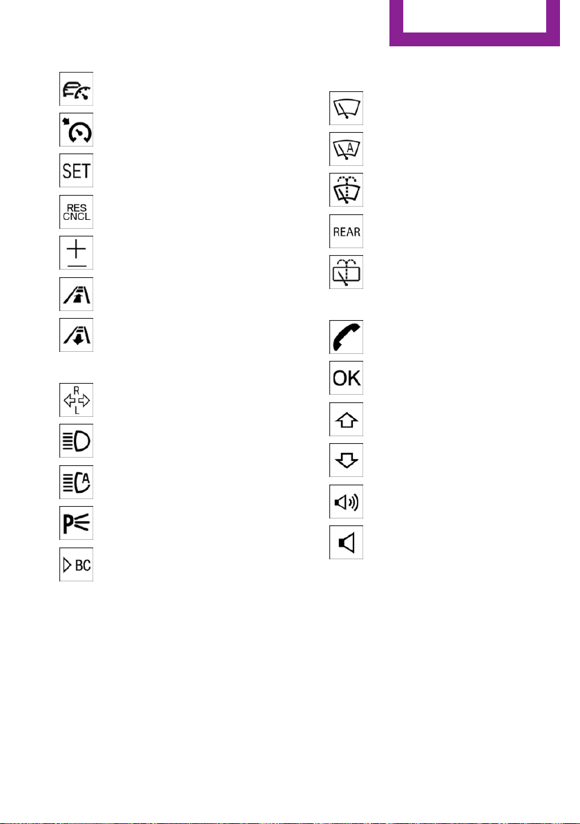
Camera-based cruise control on/
off 101
Cruise control on/off 106
Store speed 101, 106
Pause, continue cruise con‐
trol 101, 106
Set speed 101, 106
Reduce distance 101
Increase distance 101
6 Steering column stalk, left
Turn signal 54
High beams, head‐
light flasher 54
High-beam Assistant 78
Roadside parking lights 77
On-board computer 71
7 Instrument cluster 62
8 Steering column stalk, right
Windshield wipers 55
Rain sensor 55
Cleaning windows 56
Rear window wiper 56
Cleaning rear window 56
9 Steering wheel buttons, right
Telephone 164
Confirm the selection 70
Selection back 70
Selection next 70
Increase volume
Reduce volume
10 Horn
11 Adjust the steering wheel 44
12 Unlock hood 194
Seite 15
Cockpit
AT A GLANCE
15
Online Edition for Part no. 01 40 2 963 307 - VI/15
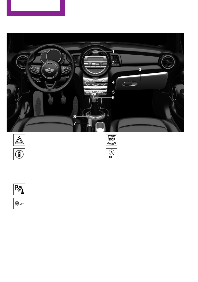
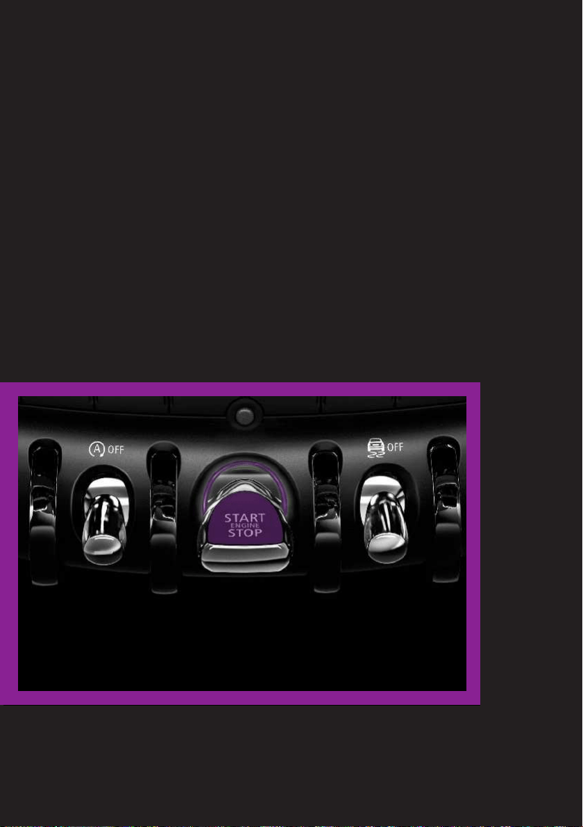
All around the center console
1 Hazard warning system 214
Intelligent Safety 90
2 Radio 151
3 Glove compartment 129
4 Climate control 115
5 PDC Park Distance Control 108
DSC Dynamic Stability Con‐
trol 97
Start/stop the engine and switch
the ignition on/off 49
Auto Start/Stop function 51
6 Steptronic transmission selector lever 58
Manual transmission selector lever 58
7 Parking brake 53
8 Driving Dynamics Control 99
Seite 16
AT A GLANCE
Cockpit
16
Online Edition for Part no. 01 40 2 963 307 - VI/15
Radio
Vehicle features and op‐
tions
This chapter describes all standard, country-
specific and optional features offered with the
series. It also describes features that are not
necessarily available in your car, e. g., due to
the selected options or country versions. This
also applies to safety-related functions and sys‐
tems. The respectively applicable country provi‐
sions must be observed when using the respec‐
tive features and systems.
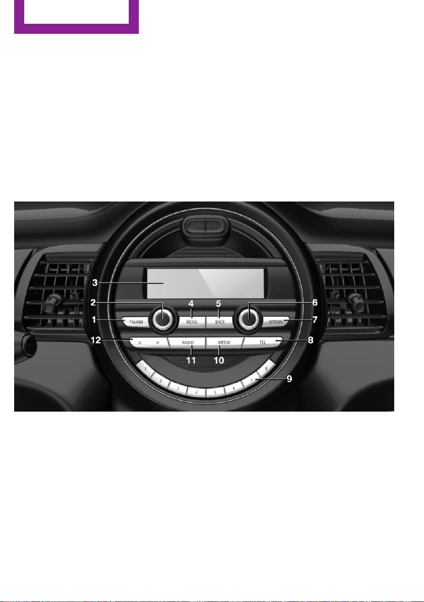
Overview
1 Change waveband
2 Volume, on/off
3 Display
4 Opening the main menu
5 Menu level back
6 Selecting menu items
▷ Turn: highlight the menu item in the
display or adjust the value.
▷ Press: select the highlighted menu item
or store the setting.
7 Open the options for the respective menu.
8 "Telephone": open the menu.
9 Programmable memory buttons
10 "Media": open the menu.
11 "Radio": open the menu.
12 Change the station or track.
Seite 18
AT A GLANCE
Radio
18
Online Edition for Part no. 01 40 2 963 307 - VI/15
Functions
Audio functions and vehicle functions can be
operated, adjusted and displayed on the radio.
▷ Radio.
▷ Multimedia.
▷ Telephone.
▷ Vehicle settings.
▷ Check Control messages.
Menu navigation
All functions of the radio can be called up via
the main menu. Some menus can also be called
up directly via the buttons on the radio.
Selecting menu items
Menu items can be selected if they are high‐
lighted.
1. Press button.
2. Turn the right-hand knob until the desired
menu item is highlighted, e.g., "Radio".
3. Press the right-hand knob again to confirm
the highlighted menu item.
Representation in the Owner's Manual
In the Owner's Manual, menu items that can be
selected are set in quotation marks, e.g.,
"Radio".
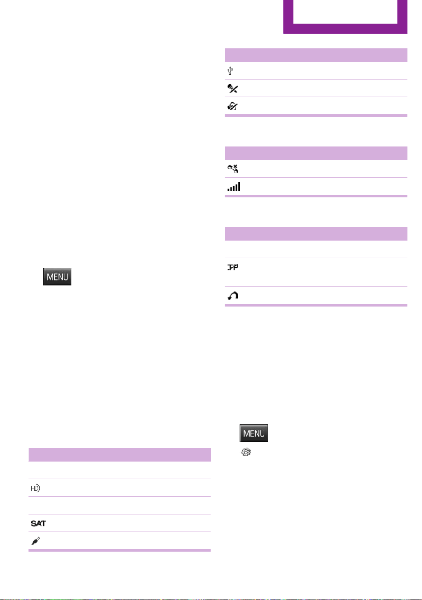
Symbols in the status field
Audio source
Symbol Meaning
FM, AM Radio waveband.
HD Radio station is being received.
SAT Satellite radio is switched on.
Satellite radio not available.
Playback via Aux In.
Symbol Meaning
Playback via USB audio interface.
Microphone muted
Tone output muted
Telephone
Symbol Meaning
Missed call
Wireless network reception strength
Traffic bulletins
Symbol Meaning
TP Traffic bulletins switched on
Traffic bulletins switched on, no traffic
bulletin stations available.
Traffic Jump
Changing settings
To set number values or values on a scale:
1.
Select the desired menu item.
2. Turn the right-hand knob to set the value.
3. Press the right-hand knob to store the
value.
Example: setting the clock
1. Press button.
2. "Settings"
3. "Time/Date"
4. "Time:"
5. Turn the right-hand knob until the desired
hour is set.
6. Press the right-hand knob to store setting.
7. Turn the right-hand knob to set the mi‐
nutes and press the right-hand knob to
save the setting.
Seite 19
Radio
AT A GLANCE
19
Online Edition for Part no. 01 40 2 963 307 - VI/15
HANDLE ME.
Online Edition for Part no. 01 40 2 963 307 - VI/15

AT A GLANCE
CONTROLS
DRIVING TIPS
ENTERTAINMENT
COMMUNICATION
MOBILITY
REFERENCE
Online Edition for Part no. 01 40 2 963 307 - VI/15
Opening and closing
Vehicle features and op‐
tions
This chapter describes all standard, country-
specific and optional features offered with the
series. It also describes features that are not
necessarily available in your car, e. g., due to
the selected options or country versions. This
also applies to safety-related functions and sys‐
tems. The respectively applicable country provi‐
sions must be observed when using the respec‐
tive features and systems.
Remote control/key
General information
The vehicle is supplied with two remote con‐
trols with integrated key.
Every remote control holds a replaceable bat‐
tery.
You may set the key functions depending on
the optional features and country-specific ver‐
sion. For Settings, refer to page 29.
The vehicle stores personal settings for every
remote control. Personal Profile, refer to
page 24.
The remote controls hold information on re‐
quired maintenance. Service data in the remote
control, refer to page 200
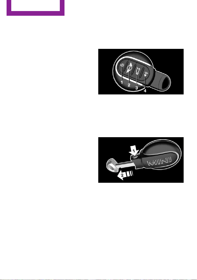
Overview
1 Unlocking
2 Locking
3 Unlock the tailgate
4 Panic mode
Integrated key
Press button, arrow 1, and remove the key, ar‐
row 2.
The integrated key fits the driver's door lock.
Replacing the battery
1.
Remove integrated key from remote con‐
trol.
2. Slide the key into the opening and raise the
cover.
Seite 22
CONTROLS
Opening and closing
22
Online Edition for Part no. 01 40 2 963 307 - VI/15
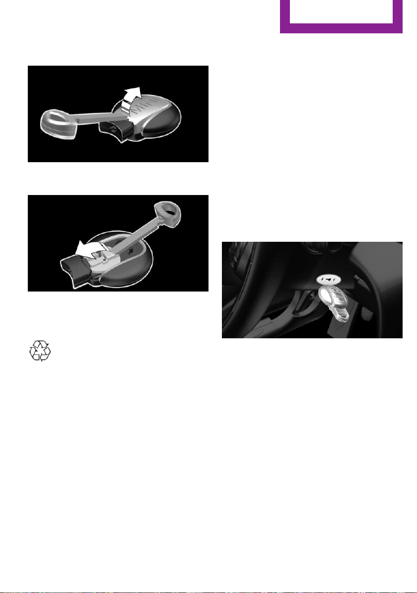
The battery compartment is accessible.
3. Slide the key in the cover of the battery
compartment and raise the cover.
4. Insert a battery of the same type with the
positive side facing up.
5. Insert lid and cover.
Have old batteries disposed of by a
dealer’s service center or another quali‐
fied service center or repair shop or
take them to a collection point.
New remote controls
New remote controls are available from a
dealer’s service center or another qualified
service center or repair shop.
Loss of the remote controls
The lost remote control can be blocked by a
dealer’s service center or another qualified
service center or repair shop.
Emergency detection of remote control
It is possible to switch on the ignition or start
the engine in situations such as the following:
▷ Interference of radio transmission to re‐
mote control by external sources e.g., by
radio masts.
▷ Empty battery in remote control.
▷ Interference from radio transmissions
through mobile devices in close proximity
to remote control.
▷ Interference of radio transmission by
charger while charging items such as mo‐
bile devices in the vehicle.
A Check Control message is displayed if an at‐
tempt is made to switch on the ignition or start
the engine.
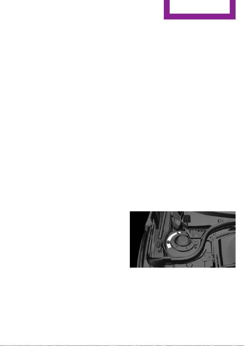
Starting the engine via emergency
detection of the remote control
Steptronic transmission: if a corresponding
Check Control message appears, hold the re‐
mote control, as shown, against the marked
area on the steering column and press the
Start/Stop button within 10 seconds while
pressing the brake.
Manual transmission: if a corresponding Check
Control message appears, hold the remote con‐
trol, as shown, against the marked area on the
steering column and press the Start/Stop but‐
ton within 10 seconds while pressing the
clutch.
Seite 23
Opening and closing
CONTROLS
23
Online Edition for Part no. 01 40 2 963 307 - VI/15

Personal Profile
The concept
Personal Profile provides three profiles, using
which personal vehicle settings can be stored.
Every remote control has one of these profiles
assigned.
If the vehicle is unlocked using a remote con‐
trol, the assigned personal profile will be acti‐
vated. All settings stored in the profile are auto‐
matically applied.
If several drivers use their own remote control,
the vehicle will adjust the personal settings dur‐
ing unlocking. These settings are also restored,
if the vehicle has been used in the meantime
by a person with a different remote control.
Changes to the settings are automatically saved
in the personal profile.
Adjusting
The settings for the following systems and func‐
tions are saved in the active profile. The scope
of storable settings is country- and equipment-
dependable.
▷ Unlocking and locking.
▷ Lights.
▷ Radio.
▷ Instrument cluster.
▷ Climate control.
▷ Park Distance Control PDC.
▷ Driving Dynamics Control.
▷ Cruise control.
▷ Intelligent Safety.
Using the remote con‐
trol
Information
WARNING
People or animals in the vehicle can lock
the doors from the inside and lock themselves
in. The vehicle can then not be opened from
the outside. There is risk of injuries. Take the
remote control along so that the vehicle can be
opened from the outside.◀
Unlocking
Press button on the remote control.
▷ The vehicle is unlocked.
▷ The interior lights are switched on, when it
is dark outside, the courtesy lamps are also
switched on. This function is not available, if
the interior lamps were switched off man‐
ually.
▷ The welcome lamps are switched on, if this
function was activated.
You can set how the vehicle is to be unlocked.
Create the settings, refer to page 29.
The alarm system, refer to page 30, is dis‐
armed.
Convenient opening
Press and hold this button on the re‐
mote control after unlocking.
The windows and the glass sunroof are opened,
as long as the button on the remote control is
pressed.
Locking
WARNING
Unlocking from the inside is only possible
with special knowledge.
Seite 24
CONTROLS
Opening and closing
24
Online Edition for Part no. 01 40 2 963 307 - VI/15
If people must spend a longer time in the vehi‐
cle while it is very hot or cold outside, there is
risk of injuries or danger to life. Do not lock the
vehicle from the outside when there are people
in it.◀
The driver's door must be closed.
Press button on the remote control.
The alarm system, refer to page 30, is armed.
If the vehicle horn honks twice when you lock
the car, this means that the engine or ignition is
still switched on. In this case, the engine or ig‐
nition must be switched off by means of the
Start/Stop button.
Switching on interior lights and
courtesy lights
Press button on the remote control
with the vehicle locked.
The courtesy lamps are only switched on when
it is dark outside. This function is not available,
if the interior lamps were switched off man‐
ually.
If the button is pressed within 10 seconds of
when the vehicle was locked Interior motion
sensor and tilt alarm sensor of the anti-theft
warning system, refer to page 31, are turned
off. After locking, wait 10 seconds before press‐
ing the button again.
Panic mode
You can trigger the alarm system if you find
yourself in a dangerous situation.
Press button on the remote control for
at least 3 seconds.
To switch off the alarm: press any button.
Unlocking the tailgate
Press button on the remote control for
approx. 1 second.
The tailgate opens slightly, regardless of
whether the vehicle was previously locked or
unlocked.
To avoid locking it into the vehicle, do not place
the remote control in the cargo area.
Depending on the features and the country
version, it is also possible to have door un‐
locked. Create the settings, refer to page 29.
If the doors were not unlocked, the tailgate is
locked again as soon as it closes.
CAUTION
Sharp-edged or pointed objects can hit
the rear window and heat conductors while
driving. There is risk of property damage. Cover
the edges and ensure that pointed objects do
not hit the rear window.◀
Malfunction
Remote control detection by the vehicle can
among others be malfunctioning under the fol‐
lowing circumstances:
▷ The battery of the remote control is dis‐
charged. Replace the battery, refer to
page 22.
▷ Interference of the radio connection from
transmission towers or other equipment
with high transmit power.
▷ Shielding of the remote control due to
metal objects.
▷ Interference of the radio connection from
mobile phones or other electronic devices
in direct proximity.
Do not transport the remote control together
with metal objects or electronic devices.
In the case of a malfunction, unlock and lock
the vehicle using the integrated key, refer to
page 26.
For US owners only
The transmitter and receiver units comply with
part 15 of the FCC/Federal Communication
Seite 25
Opening and closing
CONTROLS
25
Online Edition for Part no. 01 40 2 963 307 - VI/15
Commission regulations. Operation is governed
by the following:
FCC ID:
▷ LX8766S.
▷ LX8766E.
▷ LX8CAS.
▷ LX8CAS2.
▷ MYTCAS4.
Compliance statement:
This device complies with part 15 of the FCC
Rules. Operation is subject to the following two
conditions:
▷ This device may not cause harmful interfer‐
ence, and
▷ this device must accept any interference re‐
ceived, including interference that may
cause undesired operation.
Any unauthorized modifications or changes to
these devices could void the user's authority to
operate this equipment.
Without remote control
From the outside
WARNING
Unlocking from the inside is only possible
with special knowledge.
If people must spend a longer time in the vehi‐
cle while it is very hot or cold outside, there is
risk of injuries or danger to life. Do not lock the
vehicle from the outside when there are people
in it.◀
CAUTION
The door lock is permanently joined with
the door. The door handle can be moved.
When pulling the door handle with the
integrated key inserted, paint or key can be
damaged. There is risk of property damage. Re‐
move the integrated key before pulling the
outside door handle.◀
Unlock or lock the driver's door via the door
lock using the integrated key, refer to page 22.
The other doors must be unlocked or locked
from the inside.
To do this, unlock the lid from below with the
integrated key, arrow, and remove.
Alarm system
The alarm system is not armed if the vehicle is
locked with the integrated key.
The alarm system is triggered when the door is
opened, if the vehicle was unlocked via the
door lock. In order to terminate this alarm, un‐
lock vehicle with the remote control or switch
on the ignition, if needed, through emergency
detection of the remote control.
From the inside
Locking and unlocking
Press button.
Vehicle is locked.
Press button.
The vehicle is unlocked.
Seite 26
CONTROLS
Opening and closing
26
Online Edition for Part no. 01 40 2 963 307 - VI/15
Pressing the buttons for the central locking sys‐
tem locks and unlocks the doors and the tail‐
gate when the front doors are closed, but they
are not secured against theft.
The fuel filler flap remains unlocked.
In the event of a severe accident, the vehicle is
automatically unlocked. The hazard warning
system and interior lights come on.
Unlocking and opening
Either unlock the doors together using the cen‐
tral locking system buttons and then pull the
door handle above the armrest or pull the door
handle on the door to open the door. The other
doors remain locked.
Tailgate
Information
To avoid locking it into the vehicle, do not place
the remote control in the cargo area.
CAUTION
The tailgate swings back and up when it
opens. There is risk of property damage. Make
sure that the area of movement of the tailgate
is clear during opening and closing.◀
WARNING
Body parts can be jammed when operat‐
ing the tailgate. There is risk of injuries. Make
sure that the area of movement of the tailgate
is clear during opening and closing.◀
CAUTION
Sharp-edged or pointed objects can hit
the rear window and heat conductors while
driving. There is risk of property damage. Cover
the edges and ensure that pointed objects do
not hit the rear window.◀
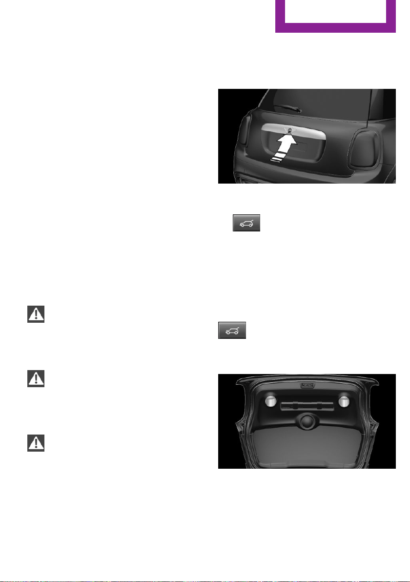
Opening from the outside
When the tailgate is opened, make sure there is
sufficient clearance to prevent damage.
▷ Unlock the vehicle and press the button on
the tailgate.
▷ Press button on the remote control
for approx. 1 second.
As the case may be, the doors are also un‐
locked. Unlocking with the remote control,
refer to page 25.
The tailgate is unlocked and can be swung up‐
ward.
Opening from the inside
With the vehicle is stationary, press the
button in the driver's footwell.
Closing
Recessed grips on the inside trim of the tailgate
can be used to conveniently pull down the tail‐
gate.
Seite 27
Opening and closing
CONTROLS
27
Online Edition for Part no. 01 40 2 963 307 - VI/15
Comfort Access
The concept
The vehicle can be accessed without activating
the remote control.
All you need to do is to have the remote control
with you, such as in your pants pocket.
The vehicle automatically detects the remote
control when it is in close proximity or in the
car's interior.
Comfort Access supports the following func‐
tions:
▷ Unlocking/locking of the vehicle.
▷ Convenient closing.
▷ Separate unlocking of the tailgate.
▷ Start the engine.
Information
To avoid locking it into the vehicle, do not place
the remote control in the cargo area.
Functional requirements
▷ There are no sources of interference
nearby.
▷ To lock the vehicle, the remote control
must be located outside of the vehicle near
the doors.
▷ The next unlocking and locking cycle is not
possible until after approx. 2 seconds.
▷ The engine can only be started if the re‐
mote control is in the vehicle.
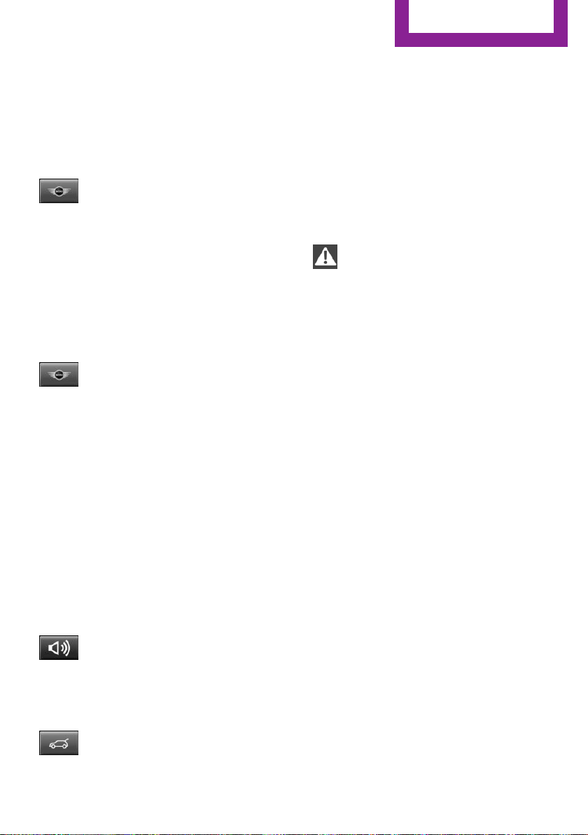
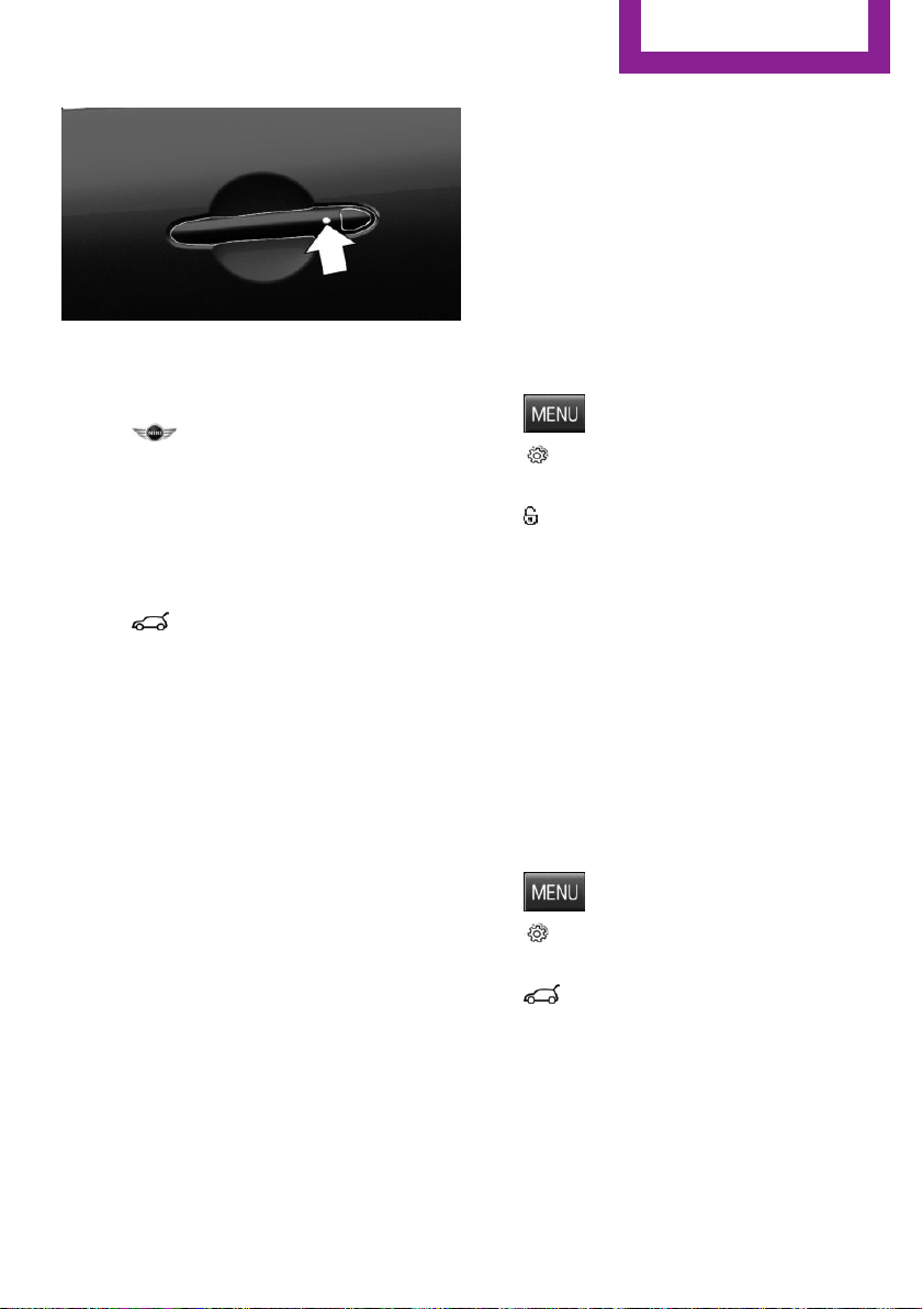
Unlocking
On the driver's or front passenger's door han‐
dle, press the button.
This corresponds to pressing the remote control
button:
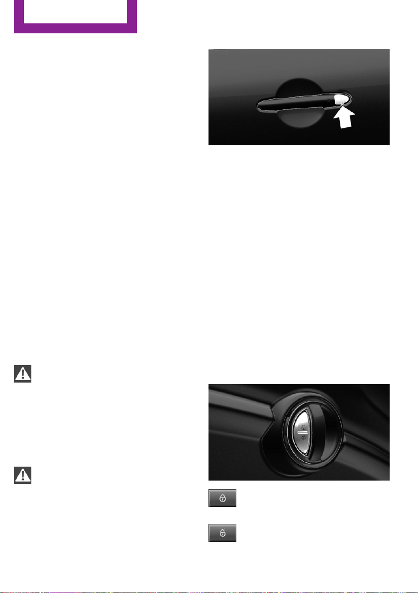
Locking
On the driver's or front passenger's door han‐
dle, press the button.
This corresponds to pressing the remote control
button:
To save battery power, ensure that all power
consumers are turned off before locking the ve‐
hicle.
Convenient closing
WARNING
With convenient closing, body parts can
be jammed. There is risk of injuries. Make sure
that the area of movement of the doors is clear
during convenient closing.◀
Seite 28
CONTROLS
Opening and closing
28
Online Edition for Part no. 01 40 2 963 307 - VI/15
Press and hold down the handle of the driver or
the front seat passenger.
This corresponds to pressing the remote control
button:
In addition to locking, the windows and glass
sunroof will be closed.
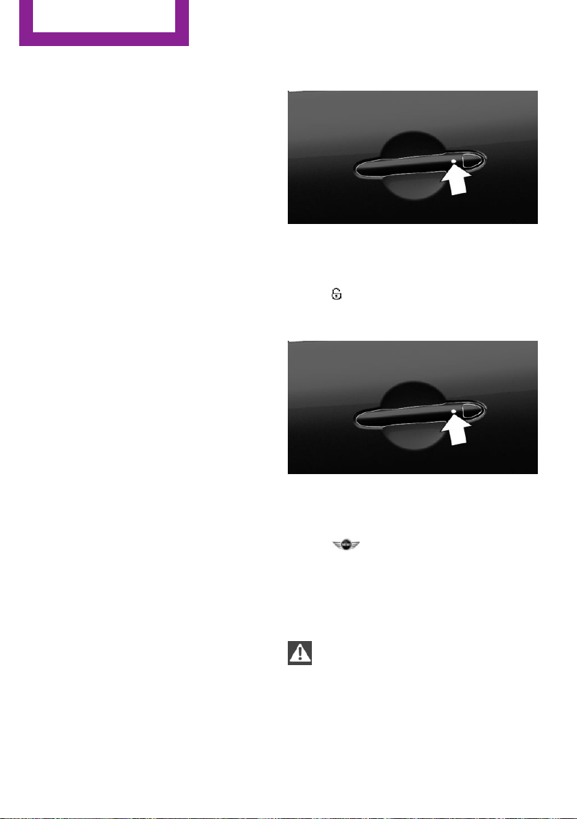
Unlocking the tailgate separately
Press button on tailgate's exterior.
This corresponds to pressing the remote control
button:
The situation of the doors does not change.
Malfunction
Remote control detection by the vehicle can
among others be malfunctioning under the fol‐
lowing circumstances:
▷ The battery of the remote control is dis‐
charged. Replace the battery, refer to
page 22.
▷ Interference of the radio connection from
transmission towers or other equipment
with high transmit power.
▷ Shielding of the remote control due to
metal objects.
▷ Interference of the radio connection from
mobile phones or other electronic devices
in direct proximity.
Do not transport the remote control together
with metal objects or electronic devices.
In the case of a malfunction, unlock and lock
the vehicle using the buttons of the remote
control or using the integrated key, refer to
page 26.
Adjusting
Unlocking
The settings are saved in the active profile. Per‐
sonal Profile, refer to page 24.
Doors
1.
Press button.
2. "Settings"
3. "Doors/Key"
4. Select the symbol.
5. Select the desired function.
▷ "All doors"
The entire vehicle is unlocked.
▷ "Driver's door"
Only the driver's door and the fuel filler
flap are unlocked. Pressing again un‐
locks the entire vehicle.
Tailgate
Depending on optional features and country
version, this setting is not offered in some
cases.
1. Press button.
2. "Settings"
3. "Doors/Key"
4. Select the symbol.
5. Select the desired function.
▷ "Tailgate"
Only the tailgate is unlocked.
▷ "Tailgate + door(s)"
The tailgate and the doors are un‐
locked.
Seite 29
Opening and closing
CONTROLS
29
Online Edition for Part no. 01 40 2 963 307 - VI/15

Locking
The settings are saved in the active profile. Per‐
sonal Profile, refer to page 24.
1.
Press button.
2. "Settings"
3. "Doors/Key"
4. Select desired setting.
▷ "Lock if no door is opened"
The vehicle locks automatically after a
short period of time if no door is
opened.
▷ "Lock after starting to drive"
The vehicle locks automatically after
you drive off.
Confirmation signals from the vehicle
1. Press button.
2. "Settings"
3. "Doors/Key"
4. Select desired setting.
▷ "Flash for lock/unlock"
Unlocking is signaled by two flashes,
locking by one.
▷ "Acoustic warning"
Unlocking is signaled by one honk of
the horn.
Alarm system
The concept
When the vehicle is locked, the vehicle alarm
system responds to:
▷ Opening a door, the hood or the tailgate.
▷ Movements in the vehicle interior.
▷ Changes in the vehicle tilt, e. g., during at‐
tempts at stealing a wheel or when towing
the car.
▷ Disconnected battery voltage.
The alarm system briefly signals tampering:
▷ Acoustic alarm.
▷ By switching on the hazard warning system.
▷ By flashing the daytime running lights.
Arming and disarming the alarm system
When you lock or unlock the vehicle, either
with the remote control or via the Comfort Ac‐
cess, the alarm system is armed or disarmed at
the same time.
Door lock and armed alarm system
The alarm system is triggered when the door is
opened, when the vehicle is unlocked via the
door lock.
Switch off the alarm, refer to page 31.
Tailgate in case of armed alarm system
The tailgate can be opened even when the
alarm system is armed.
After the tailgate is closed, it is locked and
monitored again when the doors are locked.
The hazard warning system flashes once.
Panic mode
You can trigger the alarm system if you find
yourself in a dangerous situation.
Press button on the remote control for
at least 3 seconds.
To switch off the alarm: press any button.
Seite 30
CONTROLS
Opening and closing
30
Online Edition for Part no. 01 40 2 963 307 - VI/15
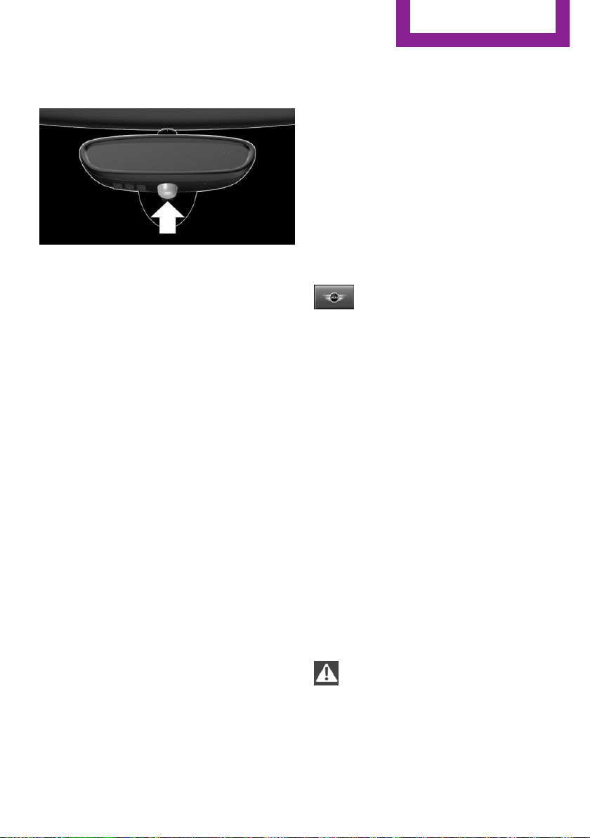
Indicator lamp on the interior rearview
mirror
▷ The indicator lamp flashes briefly every
2 seconds:
The alarm system is armed.
▷ The indicator lamp flashes after locking:
Doors, hood or tailgate are not correctly
closed. Correctly closed access points are
secured.
After 10 seconds, the indicator lamp flashes
continuously. Interior motion sensor and tilt
alarm sensor are not active.
When the still open access is closed, interior
motion sensor and tilt alarm sensor will be
switched on.
▷ The indicator lamp goes out after unlock‐
ing:
The vehicle has not been tampered with.
▷ The indicator lamp flashes after unlocking
until the engine ignition is switched on, but
no longer than approx. 5 minutes:
An alarm has been triggered.
Tilt alarm sensor
The tilt of the vehicle is monitored.
The alarm system responds in situations such as
attempts to steal a wheel or when the car is
towed.
Interior motion sensor
The windows and glass sunroof must be closed
for the system to function properly.
Avoiding unintentional alarms
The tilt alarm sensor and interior motion sensor
can be switched off together, such as in the fol‐
lowing situations:
▷ In automatic car washes.
▷ In duplex garages.
▷ During transport on trains carrying vehicles,
at sea or on a trailer.
▷ With animals in the vehicle.
Switching off the tilt alarm sensor and
interior motion sensor
Press the remote control button again
within 10 seconds as soon as the vehi‐
cle is locked.
The indicator lamp lights up for approx. 2 sec‐
onds and then continues to flash.
The tilt alarm sensor and interior motion sensor
are turned off until the vehicle is locked again.
Switching off the alarm
▷ Unlock vehicle with the remote control or
switch on the ignition, if needed through
emergency detection of remote control, re‐
fer to page 23.
▷ For Comfort Access: If you have the remote
control with you, unlock vehicle using the
button on the driver's side or passenger
side door.
Power windows
Information
WARNING
Unattended children or animals can move
the vehicle and endanger themselves and traf‐
fic, e.g. with the following actions:
▷ Pressing the Start/Stop button.
▷ Releasing the parking brake.
▷ Opening and closing of doors or windows.
Seite 31
Opening and closing
CONTROLS
31
Online Edition for Part no. 01 40 2 963 307 - VI/15
▷ Shifting the selector lever into neutral.
▷ Using vehicle equipment.
There is risk of accidents or injuries. Do not
leave children or animals unattended in the ve‐
hicle. Carry remote control along when exiting
and lock the vehicle.◀
Overview
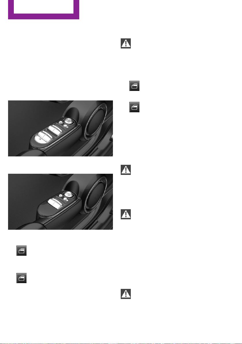
On 5-door models
On 3-door models
Opening
▷
Press the button to the resistance
point.
The window opens while the switch is held.
▷
Press the switch beyond the resist‐
ance point.
The window opens automatically. Pressing
again stops the motion.
See also: Convenient opening, refer to page 24,
via remote control.
Closing
WARNING
When operating the windows, body parts
and objects can be jammed. There is risk of in‐
juries or risk of property damage. Make sure
that the area of movement of the windows is
clear during opening and closing.◀
▷
Pull the switch to the resistance point.
The window closes while the switch is held.
▷
Pull the switch beyond the resistance
point.
The window closes automatically. Pulling
again stops the motion.
See also: closing by means of Comfort Access,
refer to page 28.
Pinch protection system
WARNING
When operating the windows, body parts
and objects can be jammed. There is risk of in‐
juries or risk of property damage. Make sure
that the area of movement of the windows is
clear during opening and closing.◀
WARNING
Accessories on the windows such as an‐
tennas can impact jam protection. There is risk
of injuries. Do not install accessories in the area
of movement of the windows.◀
If closing force exceeds a specific margin as a
window closes, closing is interrupted.
The window reopens slightly.
Closing without the pinch protection
system
WARNING
When operating the windows, body parts
and objects can be jammed. There is risk of in‐
juries or risk of property damage. Make sure
Seite 32
CONTROLS
Opening and closing
32
Online Edition for Part no. 01 40 2 963 307 - VI/15
that the area of movement of the windows is
clear during opening and closing.◀
In case of danger from the outside or if ice
might prevent normal closing, proceed as fol‐
lows:
1. Pull the switch past the resistance point and
hold it there.
The pinch protection is limited and the win‐
dow reopens slightly if the closing force ex‐
ceeds a certain margin.
2. Pull the switch past the resistance point
again within approx. 4 seconds and hold it
there.
The window closes without jam protection.
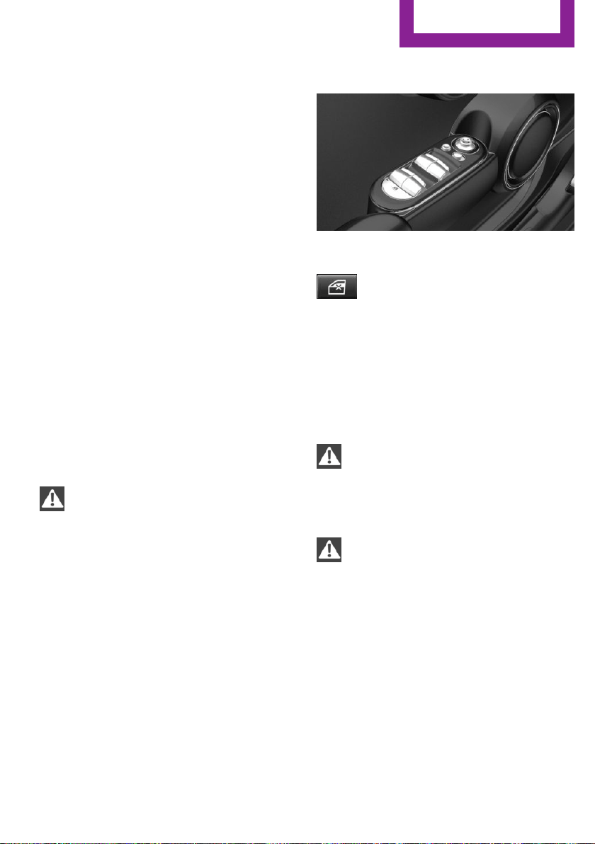
On 5-door models: safety switch
The concept
The opening and closing of the rear window
can be blocked via the safety switch for the
rear. This makes sense, for example, if children
or animals are carried in the rear.
Information
WARNING
When operating the windows, body parts
and objects can be jammed. There is risk of in‐
juries or risk of property damage. Make sure
that the area of movement of the windows is
clear during opening and closing.◀
In order to prevent uncontrolled closing of the
windows, press the safety switch, e.g. if chil‐
dren or animals are carried in the rear.
Overview
Switching on and off
Press button.
The LED lights up if the safety function
is switched on.
Panoramic glass sun‐
roof
Information
WARNING
Body parts can be jammed on operating
the glass sunroof. There is risk of injuries. Make
sure that the area of movement of the glass
sunroof is clear during opening and closing.◀
WARNING
Unattended children or animals can move
the vehicle and endanger themselves and traf‐
fic, e.g. with the following actions:
▷ Pressing the Start/Stop button.
▷ Releasing the parking brake.
▷ Opening and closing of doors or windows.
▷ Shifting the selector lever into neutral.
▷ Using vehicle equipment.
There is risk of accidents or injuries. Do not
leave children or animals unattended in the ve‐
hicle. Carry remote control along when exiting
and lock the vehicle.◀
Seite 33
Opening and closing
CONTROLS
33
Online Edition for Part no. 01 40 2 963 307 - VI/15

Overview
Tilting the glass sunroof
Press back the switch up to or
beyond the resistance point and
release it.
The glass sunroof is raised.
Opening glass sunroof
When the glass sunroof is closed
Press the switch back beyond
the resistance point and release
it twice.
The glass sunroof is opened.
Pressing the switch again stops
the motion.
With the glass sunroof completely
raised
▷ Slide switch back to the re‐
sistance point and hold.
The glass sunroof is opened
as long as the switch is
pressed.
▷ Press the switch back beyond the resist‐
ance point and release it.
The glass sunroof is opened.
Pressing the switch again stops the motion.
Comfort position
If the glass sunroof stops before it is completely
opened, it is in the Comfort position. In this po‐
sition the wind noises in the interior are the
least.
If desired, continue the movement by Pressing
the switch.
Closing glass sunroof
With the glass sunroof open
▷ Slide switch forward to the
resistance point and hold.
The glass sunroof is closed as
long as the switch is pressed
and stops in the raised posi‐
tion.
▷ Press the switch forward beyond the resist‐
ance point and release it.
The glass sunroof is closed and stops in the
raised position.
Pressing the switch toward the back stops
the motion.
▷ Press the switch forward beyond the resist‐
ance point and release it twice.
The glass sunroof is closed.
Pressing the switch again stops the motion.
With the glass sunroof completely
raised
Press the switch forward beyond
the resistance point and release
it.
The glass sunroof is closed.
Pinch protection system
If the closing force exceeds a specific value as a
glass sunroof closes, the closing action is inter‐
rupted.
The glass sunroof reopens slightly.
Seite 34
CONTROLS
Opening and closing
34
Online Edition for Part no. 01 40 2 963 307 - VI/15

WARNING
Body parts can be jammed on operating
the glass sunroof. There is risk of injuries. Make
sure that the area of movement of the glass
sunroof is clear during opening and closing.◀
Closing without the pinch protection
system
If there is an external danger, proceed as fol‐
lows:
1. Press the switch forward beyond the resist‐
ance point and hold it.
The pinch protection is limited and the
glass sunroof reopens slightly if the closing
force exceeds a certain margin.
2. Press the switch forward again beyond the
resistance point and hold until the glass
sunroof closes without jam protection.
Make sure that the closing area is clear.
Initializing after a power failure
After a power failure, it can happen that the
glass sunroof can only be raised. The system
must be initialized in this case. MINI recom‐
mends having this work performed by a deal‐
er's service center or another qualified service
center or repair shop.
Seite 35
Opening and closing
CONTROLS
35
Online Edition for Part no. 01 40 2 963 307 - VI/15
Adjusting
Vehicle features and op‐
tions
This chapter describes all standard, country-
specific and optional features offered with the
series. It also describes features that are not
necessarily available in your car, e. g., due to
the selected options or country versions. This
also applies to safety-related functions and sys‐
tems. The respectively applicable country provi‐
sions must be observed when using the respec‐
tive features and systems.
Sitting safely
The ideal seating position can make a vital con‐
tribution to relaxed, fatigue-free driving.
The seating position plays an important role in
an accident in combination with:
▷ Safety belts, refer to page 38.
▷ Head restraints, refer to page 40.
▷ Airbags, refer to page 81.
Seats
Information
WARNING
Seat adjustments while driving can lead
to unexpected movements of the seat. Vehicle
control could be lost. There is risk of an acci‐
dent. Only adjust the side on the driver's side
when the vehicle is stationary.◀
WARNING
With a backrest inclined too far to the
rear, the protective effect of the safety belt
cannot be ensured anymore. There is a danger
of sliding under the safety belt in an accident.
There is risk of injuries or danger to life. Adjust
the seat prior to starting the trip. Adjust the
backrest in an as upright position as possible
and do not adjust again while driving.◀
WARNING
There is risk of jamming when moving the
seats. There is risk of injuries or risk of property
damage. Make sure that the area of movement
of the seat is clear prior to any adjustment.◀
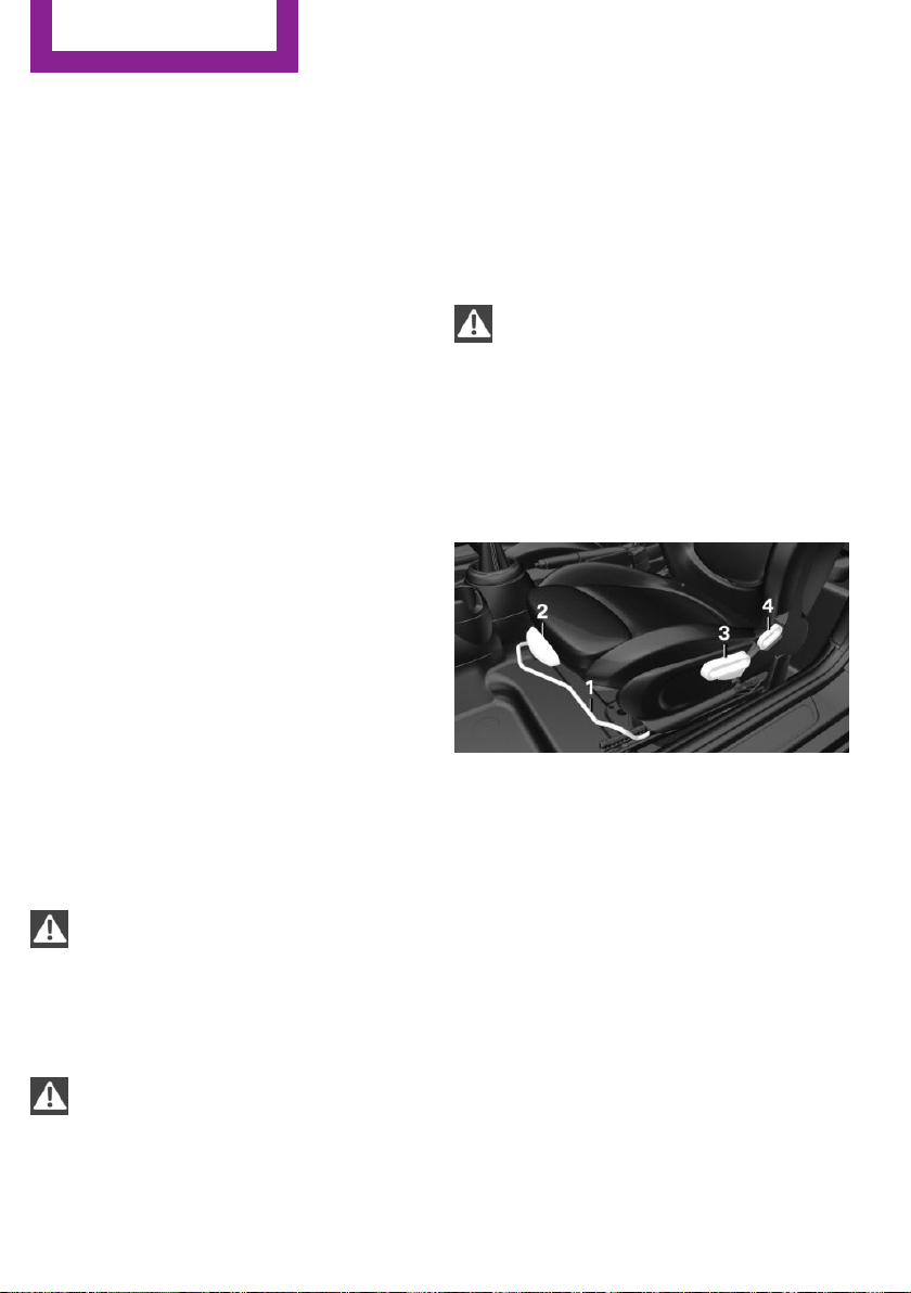
Adjusting seats
Overview
1 Forward/backward
2 Thigh support
3 Height
4 Backrest tilt
Seite 36
CONTROLS
Adjusting
36
Online Edition for Part no. 01 40 2 963 307 - VI/15
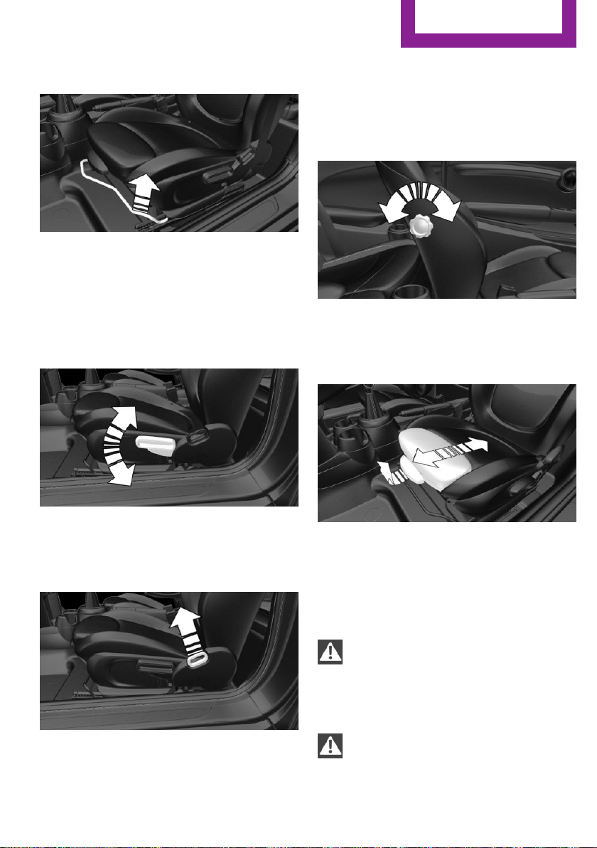
Forward/backward
Pull the lever and slide the seat in the desired
direction.
After releasing the lever, move the seat forward
or back slightly making sure it engages prop‐
erly.
Height
Pull the lever up or press it down as often as
needed to reach the desired height.
Backrest tilt
Pull the lever and apply your weight to the
backrest or lift it off, as necessary.
Lumbar support
The curvature of the seat backrest can be ad‐
justed in a way that it supports the lumbar re‐
gion of the spine. The lower back and the spine
are supported for upright posture.
Turn the wheel in order to increase or decrease
the curvature.
Thigh support
Pull the lever at the front of the seat and adjust
the thigh support.
In 3-door models: entering the rear
Information
WARNING
There is risk of jamming when moving the
seats. There is risk of injuries or risk of property
damage. Make sure that the area of movement
of the seat is clear prior to any adjustment.◀
WARNING
Unexpected movements of the backrest
while driving may occur due to an unlocked
backrest. Vehicle control could be lost. There is
Seite 37
Adjusting
CONTROLS
37
Online Edition for Part no. 01 40 2 963 307 - VI/15
risk of injuries. Fold back and lock the backrests
before driving.◀
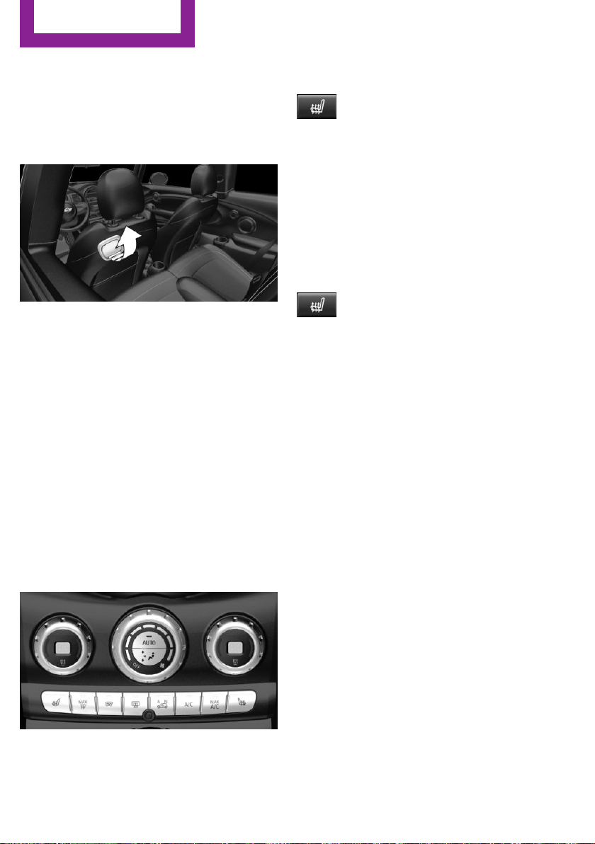
Fold down seat back
1. Pull lever up to the stop.
2. Fold backrest forward.
3. Push the seat forward.
Original position
The driver's seat features a mechanical mem‐
ory function for forward/back and backrest ad‐
justment.
1.
Push the seat back into the original posi‐
tion.
2. Fold back the backrest to lock the seat.
If the backrest is folded back when the seat is
not yet in the original position, the seat latches
in the current position. In this case, manually
adjust longitudinal direction, refer to page 37.
Front seat heating
Switching on
Press button once for each tempera‐
ture level.
The maximum temperature is reached when
three LEDs are lit.
If the journey is continued within approx. 15
minutes, the seat heating is activated automat‐
ically with the temperature selected last.
When Green mode, refer to page 143, is acti‐
vated, the heater output is reduced.
Switch off
Press button longer.
The LEDs go out.
Safety belts
Seats with safety belt
The vehicle has four or five seating positions,
each of which is equipped with a safety belt.
General information
Always make sure that safety belts are being
worn by all occupants before driving off.
For the occupants' safety the belt locking
mechanism triggers early. Slowly guide the belt
out of the holder when applying it.
If needed, disengage the belt in the rear from
the belt buckle on the side.
Although airbags enhance safety by providing
added protection, they are not a substitute for
safety belts.
The two outer safety belt buckles, integrated
into the rear seat, are for passengers sitting on
the left and right.
The center rear safety belt buckle is solely in‐
tended for the center passenger.
Seite 38
CONTROLS
Adjusting
38
Online Edition for Part no. 01 40 2 963 307 - VI/15
Information
WARNING
If the safety belt is used by more than
one person, the protective effect of the safety
belt cannot be ensured anymore. There is risk
of injuries or danger to life. Do not allow more
than one person to wear a single safety belt. In‐
fants and children are not allowed in an occu‐
pant's lap, but must be transported and respec‐
tively secured in designated child restraint
systems.◀
WARNING
The protective effect of the safety belts
can be limited or lost when safety belts are fas‐
tened incorrectly. An incorrectly fastened safety
belt can cause additional injuries, e.g. in the
event of an accident or during braking and eva‐
sive maneuvers. There is risk of injuries or dan‐
ger to life. Make sure that all occupants are
wearing safety belts correctly.◀
WARNING
With a rear backrest that is not locked,
the protective function of the middle safety belt
is not guaranteed. There is risk of injuries or
danger to life. If you are using the middle safety
belt, lock the wider rear backrest.◀
Correct use of safety belts
▷ Wear the belt twist-free and as tight to your
body as possible over your lap and should‐
ers.
▷ Wear the belt deep on your hips over your
lap. The belt may not press on your stom‐
ach.
▷ Do not wear the belt on your throat, rub it
on sharp edges, guide it or jam it in across
hard or fragile objects.
▷ Avoid thick clothing.
▷ Re-tighten the belt frequently upward
around your upper body.
Buckling the belt
General information
Make sure you hear the latch plate engage in
the belt buckle.
Unbuckling the belt
1.
Hold the belt firmly.
2. Press the red button in the belt buckle.
3. Guide the belt back into its roll-up mecha‐
nism.
Safety belt reminder for driver's seat
and front passenger seat
The indicator lamp lights up and a sig‐
nal sounds. Make sure that the safety
belts are positioned correctly. The
safety belt reminder is active at speeds above
approx. 6 mph/10 km/h. It can also be acti‐
vated if objects are placed on the front passen‐
ger seat.
Damage to safety belts
WARNING
The protective effect of the safety belts
may not be fully functional or fail in the follow‐
ing situations:
▷ Safety belts are damaged, soiled or
changed in any other way.
▷ Safety belt buckle is damaged or heavily
soiled.
▷ Belt tensioners or belt retractors were
modified.
Seite 39
Adjusting
CONTROLS
39
Online Edition for Part no. 01 40 2 963 307 - VI/15
Safety belts can be imperceptibly damaged in
the event of an accident. There is risk of injuries
or danger to life. Do not modify safety belts,
safety belt buckles, belt tensioners, belt retrac‐
tors or belt anchors and keep them clean. Have
the safety belts checked after an accident at
the dealer’s service center or another qualified
service center or repair shop.◀
Front head restraints
Information
WARNING
A missing protective effect due to re‐
moved or not correctly adjusted head restraints
can cause injuries in the head and neck area.
There is risk of injuries. Install head restraints
on occupied seats prior to driving and make
sure that the center of the head restraint sup‐
ports the back of the head at eye level.◀
WARNING
Objects on the head restraint reduce the
protective effect in the head and neck area.
There is risk of injuries.
▷ Do not use seat or head restraint covers.
▷ Do not hang objects, e.g., clothes hangers,
directly on the head restraint.
▷ Only use accessories that have been deter‐
mined to be safe for attachment to a head
restraint.
▷ Do not use any accessories, e.g. pillows,
while driving.◀
Correctly adjusted head restraint
General information
A correctly adjusted head restraint reduces the
risk of injury to cervical vertebrae in the event
of an accident.
Adjust the headrest via the backrest tilt as
needed.
Height
Adjust the head restraint so that its center is
approximately at ear level.
Distance
Adjust the distance so that the head restraint is
as close as possible to the back of the head.
If necessary, adjust the distance by adjusting
the tilt of the backrest.
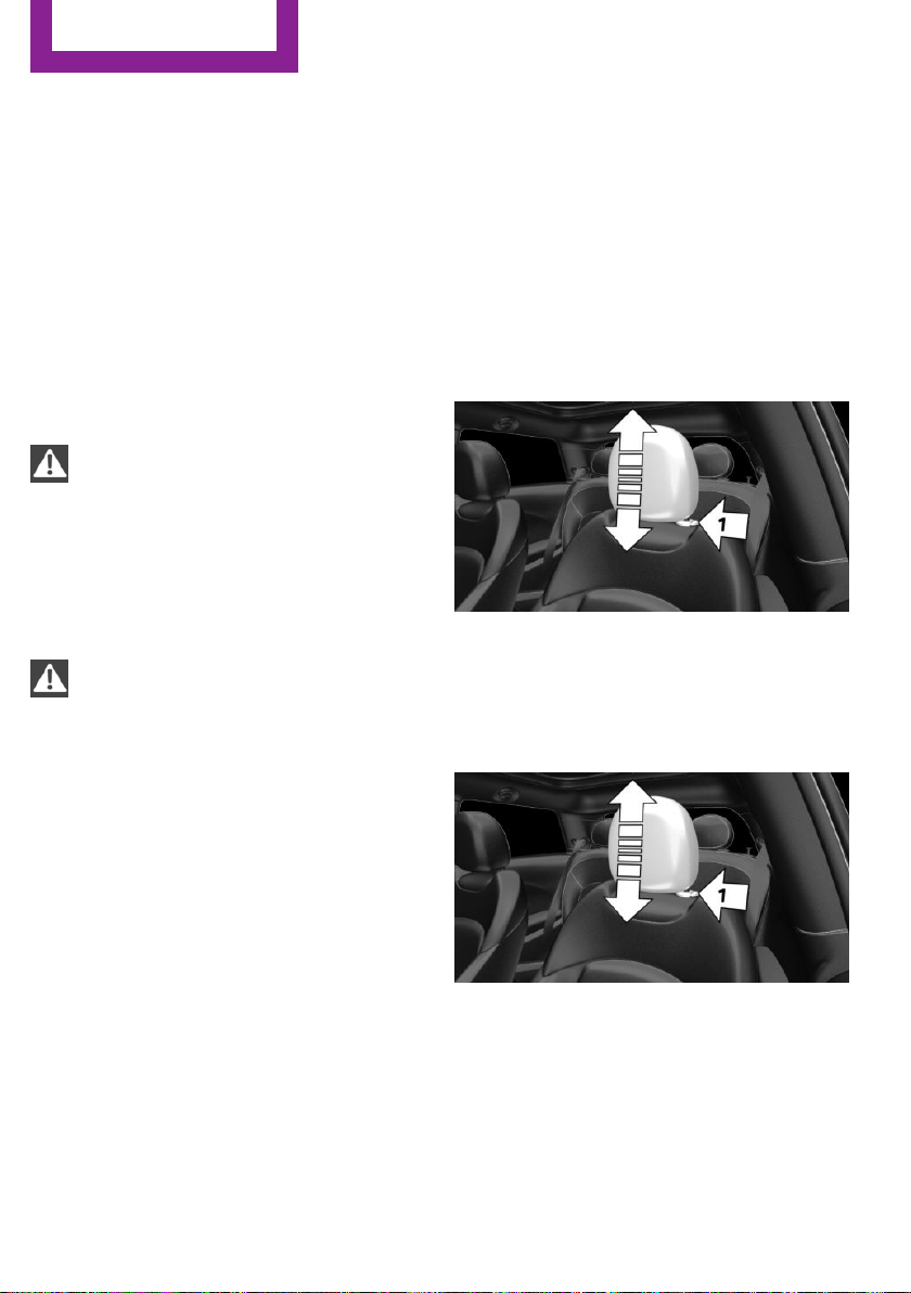
Adjusting the height
▷ To raise: pull.
▷ To lower: press button, arrow 1, and push
headrest down.
Removing
1.
Pull head restraint up as far as possible.
2. Press button, arrow 1, and pull the head re‐
straint out completely.
To remove the headrest, fold the backrest rear‐
ward if it is in the upright position.
Only remove the head restraint if no one will be
sitting in the seat in question.
Seite 40
CONTROLS
Adjusting
40
Online Edition for Part no. 01 40 2 963 307 - VI/15
Rear head restraints
Information
WARNING
A missing protective effect due to re‐
moved or not correctly adjusted head restraints
can cause injuries in the head and neck area.
There is risk of injuries. Install head restraints
on occupied seats prior to driving and make
sure that the center of the head restraint sup‐
ports the back of the head at eye level.◀
WARNING
Objects on the head restraint reduce the
protective effect in the head and neck area.
There is risk of injuries.
▷ Do not use seat or head restraint covers.
▷ Do not hang objects, e.g., clothes hangers,
directly on the head restraint.
▷ Only use accessories that have been deter‐
mined to be safe for attachment to a head
restraint.
▷ Do not use any accessories, e.g. pillows,
while driving.◀
Correctly adjusted head restraint
General information
A correctly adjusted head restraint reduces the
risk of injury to cervical vertebrae in the event
of an accident.
Height
Adjust the head restraint so that its center is
approximately at ear level.
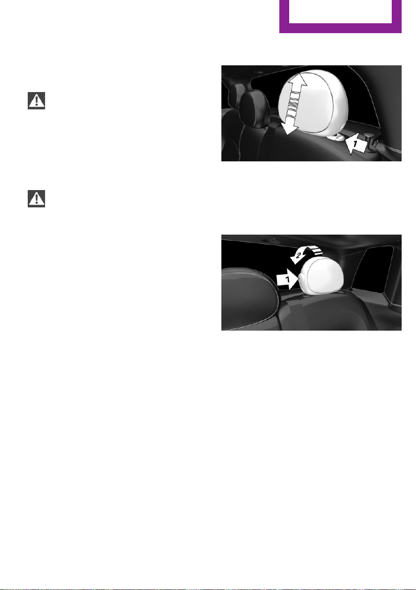
Adjusting the height
▷ To raise: push.
▷ To lower: press button, arrow 1, and push
headrest down.
Folding down
▷ To lower flaps: press the button, arrow 1,
and press down the head restraint, arrow 2.
▷ Fold back up: pull up head restraints.
Removing
Fold the seat down, refer to page 127, before
removing the head restraint, otherwise the
head restraint cannot be removed.
Seite 41
Adjusting
CONTROLS
41
Online Edition for Part no. 01 40 2 963 307 - VI/15
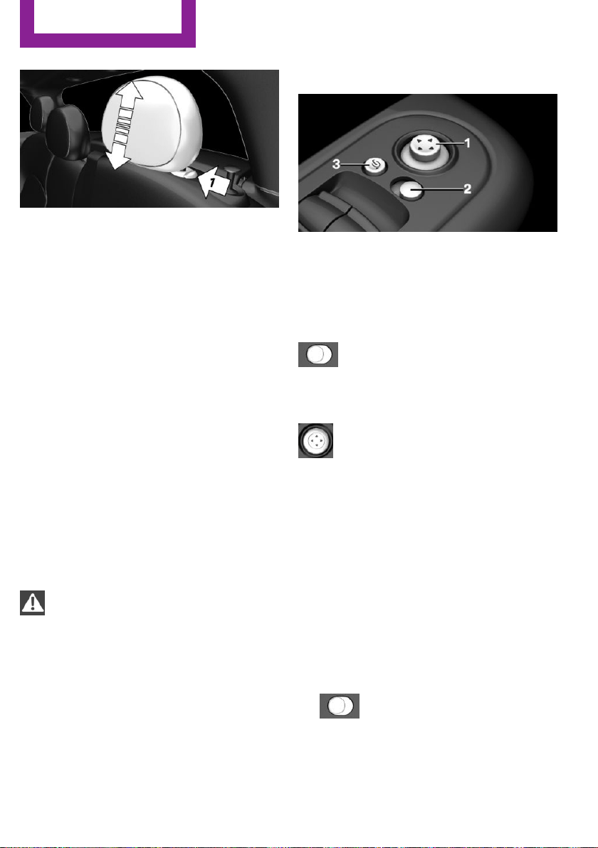
1. Pull head restraint up against the resist‐
ance.
2. Press button, arrow 1, and pull the head re‐
straint out completely.
Only remove the head restraint if no one will be
sitting in the seat in question.
Mirrors
Exterior mirrors
General information
The mirror on the passenger side is more
curved than the driver's side mirror.
Depending on the vehicle equipment, the mir‐
ror setting is stored for the profile currently
used. When the vehicle is unlocked via the re‐
mote control, the position is automatically re‐
trieved if this function is active.
Information
WARNING
Objects reflected in the mirror are closer
than they appear. The distance to the traffic
behind could be incorrectly estimated, e.g.
while changing lanes. There is risk of an acci‐
dent. Estimate the distance to the traffic behind
by looking over your shoulder.◀
Overview
1 Adjusting 42
2 Left/right, Automatic Curb Monitor
3 Fold in and out 43
Selecting a mirror
To change over to the other mirror:
Slide the switch.
Adjusting electrically
The setting corresponds to the direction
in which the button is pressed.
Adjusting manually
In case of electrical malfunction press edges of
mirror.
Automatic Curb Monitor
The concept
If reverse gear is engaged, the mirror glass on
the front passenger side is tilted downward.
This improves your view of the curb and other
low-lying obstacles when parking, e.g.
Activating
1. Slide the switch to the driver's side
mirror position.
2. Engage selector lever position R.
Seite 42
CONTROLS
Adjusting
42
Online Edition for Part no. 01 40 2 963 307 - VI/15
Deactivating
Slide the switch to the passenger side mirror
position.
Fold in and out
CAUTION
Depending on the vehicle width, the ve‐
hicle can be damaged in car washes. There is
risk of property damage. Before washing, fold
in the mirrors by hand or with the button.◀
Press button.
Possible at speeds up to approx.
15 mph/20 km/h.
Beneficial in the following situations:
▷ In car washes.
▷ On narrow roads.
▷ For folding mirrors back out that were
folded away manually.
Mirrors that were folded in are folded out auto‐
matically at a speed of approx.
25 mph/40 km/h.
Automatic heating
Both exterior mirrors are automatically heated
whenever the engine is running.
Automatic dimming feature
Both exterior mirrors are automatically dim‐
med. Photocells are used to control the Interior
rearview mirror, refer to page 43.
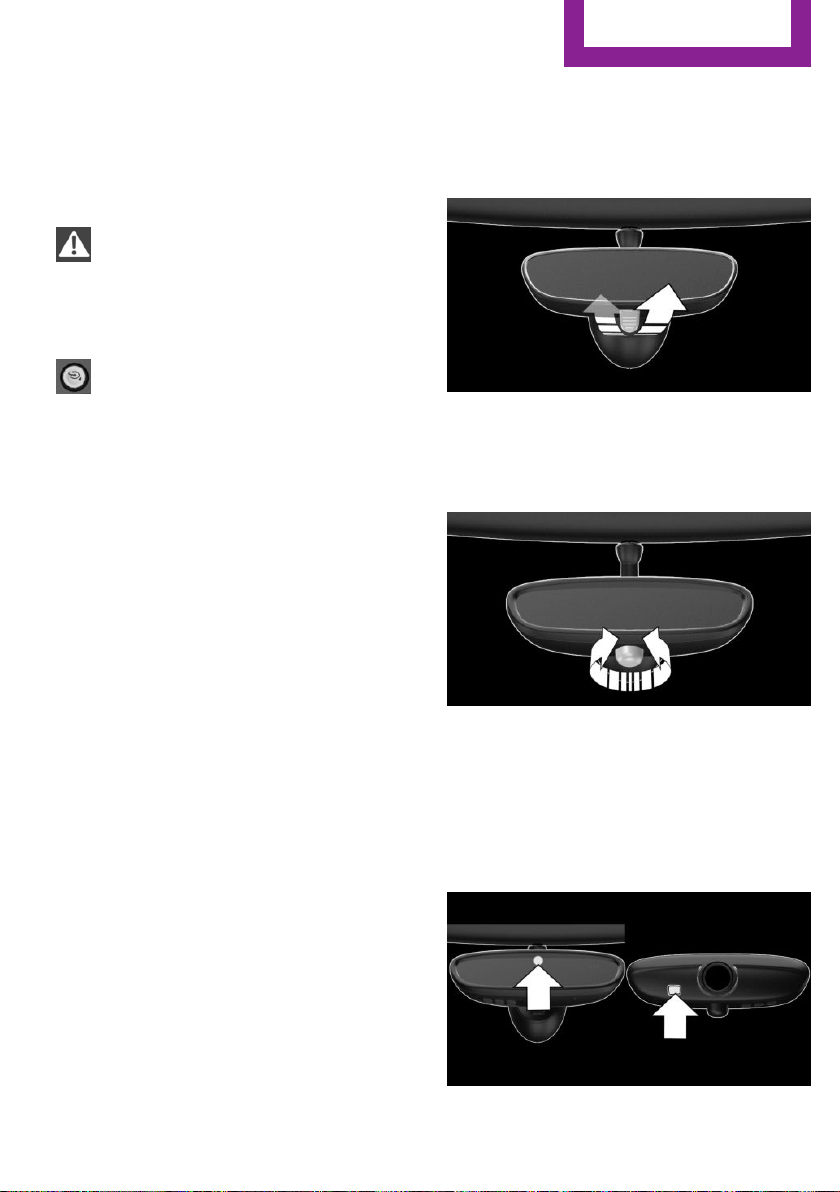
Interior rearview mirror, manually
dimmable
Flip lever
To reduce the blinding effect of the interior rear
view mirror, flip the lever forward.
Turn knob
Turn the knob to reduce the blinding effect by
the interior mirror.
Interior rearview mirror, automatic
dimming feature
The concept
Photocells are used for control:
Seite 43
Adjusting
CONTROLS
43
Online Edition for Part no. 01 40 2 963 307 - VI/15

▷ In the mirror glass.
▷ On the back of the mirror.
Functional requirement
For proper operation:
▷ Keep the photocells clean.
▷ Do not cover the area between the inside
rearview mirror and the windshield.
Steering wheel
Information
WARNING
Steering wheel adjustments while driving
can lead to unexpected steering wheel move‐
ments. Vehicle control could be lost. There is
risk of an accident. Adjust the steering wheel
while the vehicle is stationary only.◀
Adjusting
1.
Switch on the ignition.
2. Fold the lever down.
3. Move the steering wheel to the preferred
height and angle to suit your seating posi‐
tion.
4. Fold the lever back.
5. Switch off the ignition again if needed.
Seite 44
CONTROLS
Adjusting
44
Online Edition for Part no. 01 40 2 963 307 - VI/15

Transporting children safely
Vehicle features and op‐
tions
This chapter describes all standard, country-
specific and optional features offered with the
series. It also describes features that are not
necessarily available in your car, e. g., due to
the selected options or country versions. This
also applies to safety-related functions and sys‐
tems. The respectively applicable country provi‐
sions must be observed when using the respec‐
tive features and systems.
The right place for children
Information
WARNING
Unattended children or animals can move
the vehicle and endanger themselves and traf‐
fic, e.g. with the following actions:
▷ Pressing the Start/Stop button.
▷ Releasing the parking brake.
▷ Opening and closing of doors or windows.
▷ Shifting the selector lever into neutral.
▷ Using vehicle equipment.
There is risk of accidents or injuries. Do not
leave children or animals unattended in the ve‐
hicle. Carry remote control along when exiting
and lock the vehicle.◀
Children should always be in the rear
WARNING
Persons shorter than 5 ft, 150 cm cannot
correctly fasten the safety belt without suitable
additional restraint systems. The protective ef‐
fect of the safety belts can be limited or lost
when safety belts are fastened incorrectly. An
incorrectly fastened safety belt can cause addi‐
tional injuries, e.g. in the event of an accident
or during braking and evasive maneuvers.
There is risk of injuries or danger to life. Secure
persons shorter than 5 ft, 150 cm using suitable
restraint systems.◀
Accident research shows that the safest place
for children is in the back seat.
Only transport children younger than 13 years
of age or shorter than 5 ft, 150 cm in the rear in
child restraint systems provided in accordance
with the age, weight and size of the child.
Children 13 years of age or older must wear a
safety belt as soon as a suitable child restraint
system can no longer be used due to their age,
weight and size.
Children on the front passenger seat
Before using a child restraint system on the
front passenger seat, ensure that the front,
knee, and side airbags on the front passenger
side are deactivated. Automatic deactivation of
front-seat passenger airbags, refer to
page 83.
Information
WARNING
Active front-seat passenger airbags can
injure a child in a child restraint system when
the airbags are activated. There is risk of inju‐
ries. Make sure that the front-seat passenger
airbags are deactivated and that the PASSEN‐
GER AIRBAG OFF indicator lamp lights up.◀
Seite 45
Transporting children safely
CONTROLS
45
Online Edition for Part no. 01 40 2 963 307 - VI/15
WARNING
The stability of the child restraint system
is limited or compromised with incorrect seat
adjustment or improper installation of the child
seat. There is risk of injuries or danger to life.
Make sure that the child restraint system fits
securely against the backrest. If possible, adjust
the backrest tilt for all affected backrests and
correctly adjust the seats. Make sure that seats
and backrests are securely engaged. If possible,
adjust the height of the head restraints or re‐
move them.◀
Installing child re‐
straint systems
Information
Pay attention to the specifications of the child
restraint system manufacturer when selecting,
installing, and using child restraint systems.
WARNING
The stability of the child restraint system
is limited or compromised with incorrect seat
adjustment or improper installation of the child
seat. There is risk of injuries or danger to life.
Make sure that the child restraint system fits
securely against the backrest. If possible, adjust
the backrest tilt for all affected backrests and
correctly adjust the seats. Make sure that seats
and backrests are securely engaged. If possible,
adjust the height of the head restraints or re‐
move them.◀
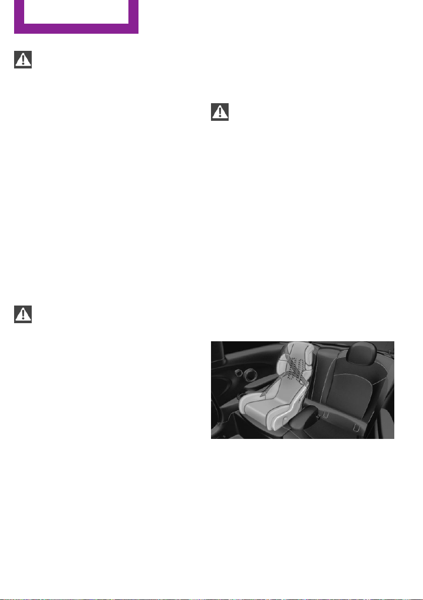
In order to faciliate the installation of a back-
facing child restraint system in the rear:
Move the front passenger's seat as far up as
possible before folding down the backrest.
On the front passenger seat
Deactivating airbags
After installing a child restraint system in the
front passenger seat, make sure that the front,
knee and side airbags on the front passenger
side are deactivated.
Deactivate the front-seat passenger airbags au‐
tomatically, refer to page 83.
WARNING
Active front-seat passenger airbags can
injure a child in a child restraint system when
the airbags are activated. There is risk of inju‐
ries. Make sure that the front-seat passenger
airbags are deactivated and that the PASSEN‐
GER AIRBAG OFF indicator lamp lights up.◀
Seat position and height
Before installing a child restraint system, move
the front passenger seat as far back as possible
and adjust its height to the highest and thus
best possible position for the belt and to offer
optimal protection in the event of an accident.
If the upper anchorage of the safety belt is lo‐
cated in front of the belt guide of the child seat,
move the passenger seat carefully forward until
the best possible belt guide position is reached.
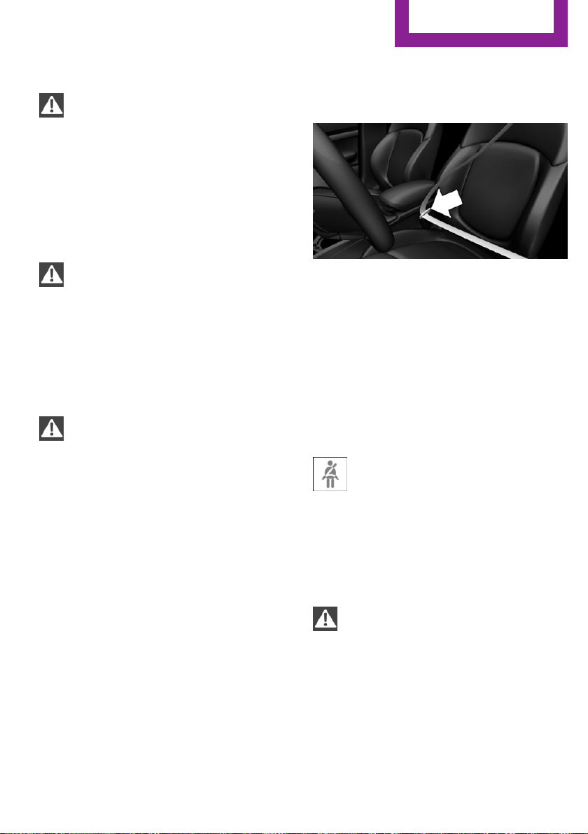
Child seat security
The rear safety belts and the front passenger
safety belt can be permanently locked to fasten
child restraint systems.
Locking the safety belt
1.
Pull out the strap completely.
2. Secure the child restraint system with the
belt.
Seite 46
CONTROLS
Transporting children safely
46
Online Edition for Part no. 01 40 2 963 307 - VI/15

3. Allow the strap to be pulled in and pull it
tight against the child restraint system. The
safety belt is locked.
Unlocking the safety belt
1. Unbuckle the belt buckle.
2. Remove the child restraint system.
3. Allow the strap to be pulled in completely.
LATCH child restraint system
LATCH: Lower Anchors and Tether for Children.
Information
Pay attention to the operating and safety infor‐
mation of the child restraint system manufac‐
turer when installing and using LATCH child re‐
straint fixing system.
Mounts for the lower LATCH anchors
The lower anchors may be used to attach the
CRS to the vehicle seat up to a combined child
and CRS weight of 65 lb when the child is re‐
strained by the internal harnesses.
Information
WARNING
If the LATCH child restraint fixing systems
are not correctly engaged, the protective effect
of the LATCH child restraint fixing system can
be limited. There is risk of injuries or danger to
life. Make sure that the lower anchors are se‐
curely engaged and that the LATCH child re‐
straint fixing system fits securely against the
backrest.◀
Position
The corresponding symbol shows the
mounts for the lower LATCH anchors.
Seats equipped with lower anchors are
marked with a pair, 2, of LATCH sym‐
bols. It is not recommended to use the
inner lower anchors of standard outer
LATCH positions to fasten a child restraint sys‐
tem on the middle seat. Use the vehicle seat
belt instead for the middle seat.
Before installing LATCH child restraint
systems
Pull the belt away from the area of the child re‐
straint system.
Assembly of LATCH child restraint
systems
1. Install child restraint system, see manufac‐
turer's information.
2. Ensure that both LATCH anchors are prop‐
erly connected.
Child restraint fixing system with a
tether strap
Information
CAUTION
The mounting points for the upper retain‐
ing straps of child restraint systems are only
provided for these retaining straps. When other
objects are mounted, the anchors can be dam‐
aged. There is risk of property damage. Only
mount child restraint systems to the upper re‐
taining straps.◀
Mounting points
The respective symbol shows the an‐
chor for the upper retaining strap. Seats
with an upper Top Tether are marked
Seite 47
Transporting children safely
CONTROLS
47
Online Edition for Part no. 01 40 2 963 307 - VI/15
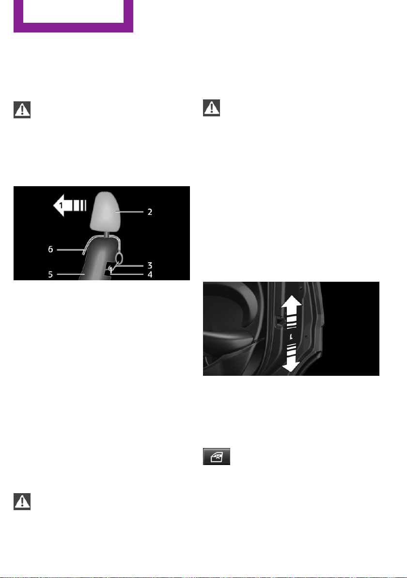
with this symbol. It can be found on the rear
seat backrest or the rear window shelf.
Retaining strap guide
WARNING
If the upper retaining strap is incorrectly
used for the child restraint system, the protec‐
tive effect can be reduced. There is risk of inju‐
ries. Make sure that the upper retaining strap is
not guided across sharp edges and without
twisting to the upper retaining strap.◀
1 Direction of travel
2 Head restraint
3 Hook for upper retaining strap
4 Mounting point
5 Seat backrest
6 Upper retaining strap
Attaching the upper retaining strap to
the mounting point
1.
Raise the head restraint if needed.
2. Guide the upper retaining strap between
the supports of the head restraint.
3. Attach the hook of the retaining strap to
the anchor on the back seat.
4. Tighten the retaining strap by pulling it
down.
WARNING
In case of an accident, people sitting in
the back can come into contact with the tight‐
ened retaining strap of the child restraint sys‐
tem on the front passenger seat. There is risk of
injuries or danger to life. With a mounted child
restraint system, do not carry any people on
the rear seat behind the front passenger seat.◀
WARNING
If the rear backrest is not locked, the pro‐
tective effect of the child restraint system is lim‐
ited or there is none. In particular situations,
e.g. braking maneuvers or in case of an acci‐
dent, the rear backrest can fold forward. There
is risk of injuries or danger to life. Make sure
that the rear backrests are locked.◀
ON 5-door models: Lock‐
ing the doors and win‐
dows
Doors
Push the locking lever on the rear doors up.
The door can now be opened from the outside
only.
Safety switch for the rear
Press button on the driver's door if
children are being transported in the
rear.
This locks various functions so that they cannot
be operated from the rear: safety switch, refer
to page 33.
Seite 48
CONTROLS
Transporting children safely
48
Online Edition for Part no. 01 40 2 963 307 - VI/15

Driving
Vehicle features and op‐
tions
This chapter describes all standard, country-
specific and optional features offered with the
series. It also describes features that are not
necessarily available in your car, e. g., due to
the selected options or country versions. This
also applies to safety-related functions and sys‐
tems. The respectively applicable country provi‐
sions must be observed when using the respec‐
tive features and systems.
Start/Stop button
The concept
Pressing the Start/Stop button
switches the ignition on or off
and starts the engine.
Steptronic transmission: the en‐
gine starts in selector lever posi‐
tion P or N with the brake pedal pressed when
you press the Start/Stop button.
Manual transmission: the engine starts with the
clutch pedal pressed when the Start/Stop but‐
ton is pressed.
Ignition on
Steptronic transmission: press the Start/Stop
button, and do not press on the brake pedal at
the same time.
Manual transmission: press the Start/Stop but‐
ton without stepping on the clutch pedal.
All vehicle systems are ready for operation.
Most of the indicator and warning lights in the
instrument cluster light up for a varied length of
time.
To save battery power when the engine is off,
switch off the ignition and any unnecessary
electronic systems/power consumers.
Ignition off
Manual transmission: press the Start/Stop but‐
ton again without stepping on the clutch pedal.
Steptronic transmission: shift to selector lever
position P, press the Start/Stop button again
without stepping on the brake.
All indicator lights in the instrument cluster go
out.
To save battery power when the engine is off,
switch off the ignition and any unnecessary
electronic systems/power consumers.
The ignition is switched off automatically in the
following situations while the vehicle is station‐
ary and the engine is off:
▷ During locking, also with the low beams ac‐
tivated.
▷ Shortly before the battery is discharged
completely, so that the engine can still be
started. This function is only available when
the low beams are turned off.
▷ When opening and closing the driver door,
if the driver's safety belt is unbuckled and
the low beams are turned off.
▷ While the driver's safety belt is unbuckled
with driver's door open and low beams off.
▷ The low beams switch to parking lights af‐
ter approx. 15 minutes of no use.
Radio ready state
Activate radio-ready state: when the engine is
running: press the Start/Stop button.
Some electronic systems/power consumers re‐
main ready for operation.
The radio-ready state is switched off automati‐
cally in the following situations:
Seite 49
Driving
CONTROLS
49
Online Edition for Part no. 01 40 2 963 307 - VI/15

▷ After approx. 8 minutes.
▷ When the vehicle is locked using the central
locking system.
▷ Shortly before the battery is discharged
completely, so that the engine can still be
started.
The radio-ready state remains active if, e.g., the
ignition is automatically switched off for the fol‐
lowing reasons:
▷ Opening or closing the driver's door.
▷ Unfastening of the driver's safety belt.
▷ When automatically switching from low
beams to parking lights.
If the engine is switched off and the ignition is
switched on, the system automatically switches
to the radio-ready state if the lights are turned
off or, if correspondingly equipped, the day‐
time running lights are activated.
Starting the engine
Information
DANGER
If the exhaust pipe is blocked or ventila‐
tion is insufficient, harmful exhaust gases can
enter into the vehicle. The exhaust gases con‐
tain carbon monoxide, an odorless and color‐
less but highly toxic gas. In enclosed areas, ex‐
haust gases can also accumulate outside of the
vehicle. There is danger to life. Keep the ex‐
haust pipe free and ensure sufficient ventila‐
tion.◀
WARNING
An unsecured vehicle can put itself into
motion and roll away. There is risk of an acci‐
dent. Before exiting, secure the vehicle against
rolling.
In order to ensure that the vehicle is secured
against rolling away, observe the following:
▷ Set the parking brake.
▷ On uphill grades or on a slope, turn the
front wheels in the direction of the curb.
▷ On uphill grades or on a slope, also secure
the vehicle, e.g. with a wheel chock.◀
CAUTION
In the case of repeated starting attempts
or repeated starting in quick succession, the
fuel is not burned or is inadequately burned.
The catalytic converter can overheat. There is
risk of property damage. Avoid repeated start‐
ing in quick succession.◀
Steptronic transmission
Starting the engine
1.
Depress the brake pedal.
2. Engage selector lever position P or N.
3. Press the Start/Stop button.
The ignition is activated automatically for a cer‐
tain time and is stopped as soon as the engine
starts.
Manual transmission
Starting the engine
1.
Depress the brake pedal.
2. Press on the clutch pedal and shift to neu‐
tral.
3. Press the Start/Stop button.
The ignition is activated automatically for a cer‐
tain time and is stopped as soon as the engine
starts.
Engine stop
Information
WARNING
Unattended children or animals can move
the vehicle and endanger themselves and traf‐
fic, e.g. with the following actions:
Seite 50
CONTROLS
Driving
50
Online Edition for Part no. 01 40 2 963 307 - VI/15

▷ Pressing the Start/Stop button.
▷ Releasing the parking brake.
▷ Opening and closing of doors or windows.
▷ Shifting the selector lever into neutral.
▷ Using vehicle equipment.
There is risk of accidents or injuries. Do not
leave children or animals unattended in the ve‐
hicle. Carry remote control along when exiting
and lock the vehicle.◀
WARNING
An unsecured vehicle can put itself into
motion and roll away. There is risk of an acci‐
dent. Before exiting, secure the vehicle against
rolling.
In order to ensure that the vehicle is secured
against rolling away, observe the following:
▷ Set the parking brake.
▷ On uphill grades or on a slope, turn the
front wheels in the direction of the curb.
▷ On uphill grades or on a slope, also secure
the vehicle, e.g. with a wheel chock.◀
Before driving into a car wash
So that the vehicle can roll into a car wash ob‐
serve instructions for going into an automatic
car wash, refer to page 220.
Steptronic transmission
Switching off the engine
1.
Engage selector lever position P with the
vehicle stopped.
2. Press the Start/Stop button.
The engine is switched off.
The radio-ready state is switched on.
3. Set the parking brake.
Manual transmission
Switching off the engine
1. With the vehicle at a standstill, press the
Start/Stop button.
The engine is switched off.
The radio-ready state is switched on.
2. Shift into first gear or reverse.
3. Set the parking brake.
Auto Start/Stop function
The concept
The Auto Start/Stop function helps save fuel.
The system switches off the engine during a
stop, e.g., in traffic congestion or at traffic
lights. The ignition remains switched on. The
engine starts again automatically for driving off.
Automatic operation
After every start of the engine using the Start/
Stop button, the Auto Start/Stop function is in
the last selected state, refer to page 53. When
the Auto Start/Stop function is active, it is avail‐
able when the vehicle is traveling faster than
about 3 mph, approx. 5 km/h.
Engine stop
The engine is switched off automatically during
a stop under the following conditions:
Manual transmission:
▷ Neutral is engaged and the clutch pedal is
not pressed.
▷ The driver's safety belt is buckled or the
driver's door is closed.
Steptronic transmission:
▷ The selector lever is in selector lever posi‐
tion D.
▷ Brake pedal remains depressed while the
vehicle is stopped.
Seite 51
Driving
CONTROLS
51
Online Edition for Part no. 01 40 2 963 307 - VI/15

▷ The driver's safety belt is buckled or the
driver's door is closed.
In order to be able to release the brake pedal,
engage lever in position P. The engine remains
off.
To continue driving depress the brake pedal.
When a gear is engaged, the engine starts au‐
tomatically.
The air flow from the air conditioner is reduced
when the engine is switched off.
Displays in the instrument cluster
The display indicates that the
Auto Start/Stop function is ready
for an Automatic engine start.
The display indicates that the
conditions for an automatic en‐
gine stop have not been met.
Functional limitations
The engine is not switched off automatically in
the following situations:
▷ External temperature too low.
▷ The external temperature is high and auto‐
matic climate control is running.
▷ The car's interior has not yet been heated
or cooled to the required level.
▷ The engine is not yet at operating tempera‐
ture.
▷ The wheels are at a sharp angle or the
steering wheel is being turned.
▷ After driving in reverse.
▷ Fogging of the windows when the auto‐
matic climate control is switched on.
▷ The vehicle battery charge is very low.
▷ At higher elevations.
▷ The engine compartment lid is unlocked.
▷ The parking assistant is activated.
▷ Stop-and-go traffic.
▷ Selector lever in selector lever position R, N
or M/S.
Starting the engine
The engine starts automatically under the fol‐
lowing conditions:
▷ Manual transmission:
The clutch pedal is pressed.
▷ Steptronic transmission:
By releasing the brake pedal.
After the engine starts, accelerate as usual.
Safety mode
After the engine switches off automatically, it
will not start again automatically if any one of
the following conditions are met:
▷ The driver's safety belt is unbuckled and
the driver's door is open.
▷ The hood was unlocked.
Some indicator lights light up for a varied
length of time.
The engine can only be started via the Start/
Stop button.
Functional limitations
Even if driving off was not intended, the deacti‐
vated engine starts up automatically in the fol‐
lowing situations:
▷ Excessive warming of the car's interior
when the cooling function is switched on.
▷ The steering wheel is turned.
▷ Steptronic transmission: change from selec‐
tor lever position D to R, N or M/S.
▷ Steptronic transmission: change from selec‐
tor lever position P to R, N, D or M/S.
▷ The vehicle begins rolling.
▷ Fogging of the windows when the auto‐
matic climate control is switched on.
Seite 52
CONTROLS
Driving
52
Online Edition for Part no. 01 40 2 963 307 - VI/15
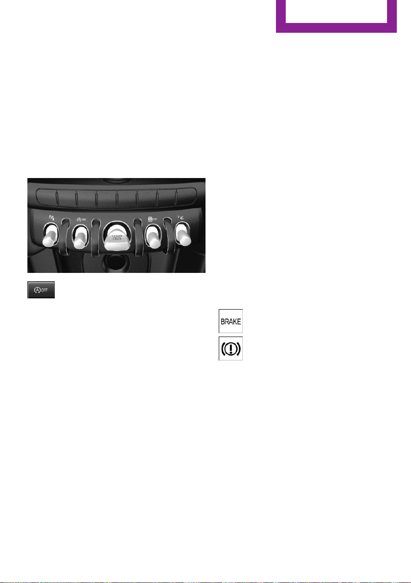
▷ The vehicle battery charge is very low.
▷ Excessive cooling of the car's interior when
the heating is switched on.
▷ Manual transmission: low brake vacuum
pressure; this can occur, e.g., if the brake
pedal is depressed a number of times in
succession.
Switching the system on/off
Using the button
Press button.
▷ LED comes on: Auto Start/Stop function is
deactivated.
The engine is started during an automatic
engine stop.
The engine can only be stopped or started
via the Start/Stop button.
▷ LED goes out: Auto Start/Stop function is
activated.
Switching off the vehicle during an
automatic engine stop
During an automatic engine stop, the vehicle
can be switched off permanently, e. g., when
leaving it.
1.
Steptronic transmission: engage selector
lever position P.
2. Press the Start/Stop button. The ignition is
switched off. The Auto Start/Stop function is
deactivated.
3. Manual transmission: shift into first gear or
reverse.
4. Set the parking brake.
Engine start as usual via Start/Stop button.
Automatic deactivation
In certain situations, Auto Start/Stop function is
deactivated automatically for safety reasons as
if the driver were absent.
Malfunction
The Auto Start/Stop function no longer switches
off the engine automatically. A Check Control
message is displayed. It is possible to continue
driving. Have the system checked.
Parking brake
Applying
The lever automatically engages after being
pulled up.
The indicator lamp lights up red. The
parking brake is set.
Lower lamp: indicator lamp in Canadian
models
If for once use during driving is required, en‐
gage the parking brake slightly and hold the
button down.
To prevent corrosion and one-sided brake ac‐
tion, lightly apply the parking brake periodically
while coasting, if traffic conditions permit.
The brake lights will not light up if the parking
brake is set.
Seite 53
Driving
CONTROLS
53
Online Edition for Part no. 01 40 2 963 307 - VI/15
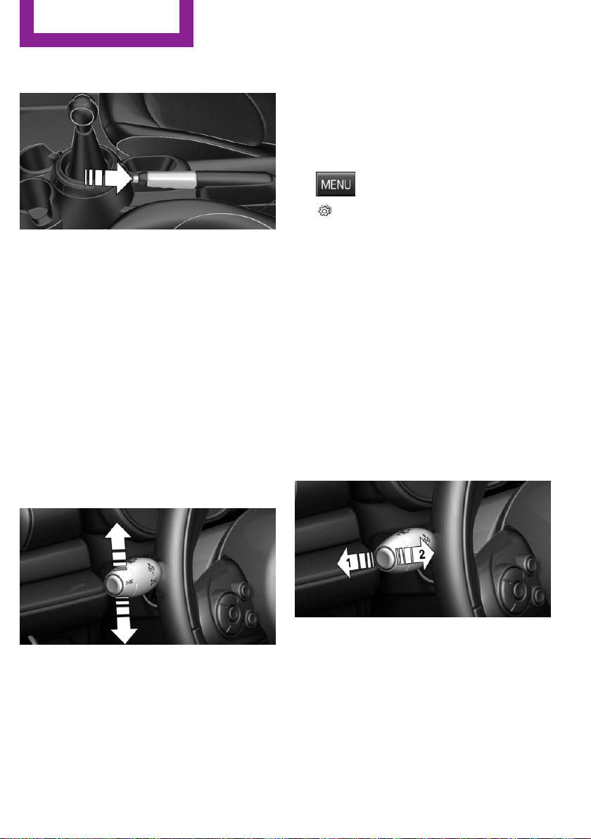
Releasing
Raise lever slightly, press the button and guide
the lever down.
Turn signal, high beams,
headlight flasher
Turn signal
Turn signal in exterior mirror
When driving and during operation of the turn
signals or hazard warning system, do not fold in
the exterior mirrors, so that the signal lights on
the exterior mirror are easy to see.
Using turn signals
Press the lever beyond the resistance point.
The turn signal lever returns into is starting po‐
sition after actuation.
To switch off manually, slightly tap the lever to
the resistance point.
Triple turn signal activation
Slightly tap lever.
The turn signal flashes three times.
The function can be activated or deactivated.
Set via radio.
1.
Press button.
2. "Settings"
3. "Lighting"
4. "Triple turn signal"
Settings are stored for the profile currently
used.
Signaling briefly
Press the lever to the resistance point and hold
it there for as long as you want the turn signal
to flash.
Malfunction
Unusually rapid flashing of the indicator lamp
indicates that a turn signal bulb has failed.
High beams, headlight flasher
▷ High beams, arrow 1.
▷ Headlight flasher, arrow 2.
Seite 54
CONTROLS
Driving
54
Online Edition for Part no. 01 40 2 963 307 - VI/15
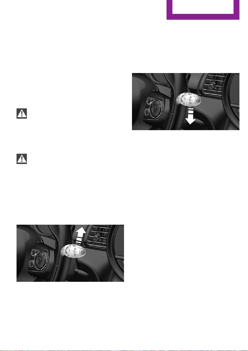
Washer/wiper system
Switching the wipers on/off and brief
wipe
General information
Do not use the wipers if the windshield is dry,
as this may damage the wiper blades or cause
them to become worn more quickly.
Information
CAUTION
If the wipers are frozen to the windshield,
the wiper blades can be torn off and the wiper
motor overheat on switching on. There is risk of
property damage. Defrost the windshield prior
to switching the wipers on.◀
WARNING
If the wipers start moving in the folded
away state, damage may occur to parts of the
vehicle or body parts can be jammed. There is
risk of injuries or risk of property damage. Make
sure that the vehicle is switched off when the
wipers are in the folded away state and the
wipers are folded in when switching on.◀
Switching on
The lever automatically returns to its initial po‐
sition when released.
▷ Normal wiper speed: tap up once.
The wipers switch to intermittent operation
when the vehicle is stationary.
▷ Fast wiper speed: tap up twice or tap once
beyond the resistance point.
Wipers change to normal speed when vehi‐
cle comes to standstill.
Switch off and brief wipe
The lever automatically returns to its initial po‐
sition when released.
▷ Single wipe: press down once.
▷ To switch off from normal wiper speed:
press down once.
▷ To switch off from fast wiper speed: press
down twice.
Interval mode or rain sensor
The concept
Without the rain sensor, the frequency of the
wiper operation is preset.
The rain sensor automatically controls the time
between wipes depending on the intensity of
the rainfall. The sensor is located on the wind‐
shield, directly behind the interior rearview mir‐
ror.
Seite 55
Driving
CONTROLS
55
Online Edition for Part no. 01 40 2 963 307 - VI/15
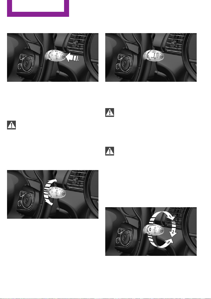
Activating/deactivating
Press button on the wiper lever.
Wiping is started. If the vehicle is equipped with
a rain sensor: LED in wiper lever lights up.
When wipers are frozen to windshield, wiper
operation is deactivated.
CAUTION
If the rain sensor is activated, the wipers
can accidentally start moving in car washes.
There is risk of property damage. Deactivate
the rain sensor in car washes.◀
Setting the frequency or sensitivity of
the rain sensor
Turn the thumbwheel to adjust the frequency
or sensitivity of the rain sensor.
Up: short interval or high sensitivity of the rain
sensor.
Down: long interval or low sensitivity of the rain
sensor.
Washing the windshield
Pull the wiper lever towards you.
The system sprays washer fluid on the wind‐
shield and activates the wipers briefly.
WARNING
The washer fluid can freeze onto the win‐
dow at low temperatures and obstruct the
view. There is risk of an accident. Only use the
washer systems, if the washer fluid cannot
freeze. Use antifreeze if needed.◀
CAUTION
When the wiper water container is empty,
the wash pump cannot work as intended.
There is risk of property damage. Do not use
the washer system when the wash water con‐
tainer is empty.◀
Rear window wiper
Switching on the rear window wiper
Turn the switch from idle position 0 upward, ar‐
row 1: interval mode. When reverse gear is en‐
Seite 56
CONTROLS
Driving
56
Online Edition for Part no. 01 40 2 963 307 - VI/15
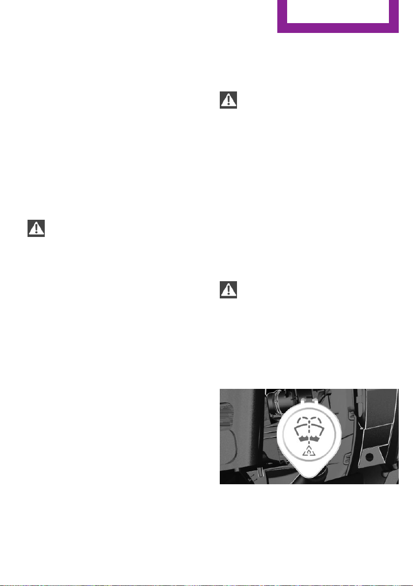
gaged, the system switches to continuous op‐
eration.
Cleaning rear window
In interval mode: turn the switch further, ar‐
row 2. The switch automatically returns to its
interval position when released.
In idle position: turn switch downward, arrow 3.
The switch automatically returns to its idle posi‐
tion when released.
Fold-out position of the wipers
Helpful when changing the wiper blades or un‐
der frosty conditions, e.g.
WARNING
If the wipers start moving in the folded
away state, damage may occur to parts of the
vehicle or body parts can be jammed. There is
risk of injuries or risk of property damage. Make
sure that the vehicle is switched off when the
wipers are in the folded away state and the
wipers are folded in when switching on.◀
1.
Switch the ignition on and off again.
2. With icy conditions make sure that blades
are not frozen to the windshield.
3. Press the wiper lever up beyond the point
of resistance and hold it for approx. 3 sec‐
onds, until the wiper remains in a nearly
vertical position.
After the wipers are folded back down, the
wiper system must be reactivated.
1.
Switch on the ignition.
2. Push wiper lever down. Wipers move to
their resting position and are ready again
for operation.
Washer fluid
Information
WARNING
Some antifreeze agents can contain
harmful substances and are flammable. There
is risk of fire and risk of injuries. Observe the in‐
structions on the containers. Keep antifreeze
away from ignition sources. Do not refill oper‐
ating materials into different bottles. Store op‐
erating materials out of reach of children.
United States: The washer fluid mixture ratio is
regulated by the U.S. EPA and many individual
states; do not exceed the allowable washer
fluid dilution ratio limits that apply. Follow the
usage instructions on the washer fluid con‐
tainer.
Use of BMW’s Windshield Washer Concentrate
or the equivalent is recommended.◀
WARNING
Improperly executed work under the
hood can damage components and lead to a
safety risk. There is risk of accidents or risk of
property damage. Have work under the hood
be executed by a dealer’s service center or an‐
other qualified service center or repair shop.◀
Washer fluid reservoir
All washer nozzles are supplied from one reser‐
voir in the engine compartment.
Fill with a mixture of windshield washer con‐
centrate and tap water and – if required – with
Seite 57
Driving
CONTROLS
57
Online Edition for Part no. 01 40 2 963 307 - VI/15

a washer antifreeze, according to the manufac‐
turer's recommendations.
Mix the washer fluid before adding to find the
right mixture.
Do not add windshield washer concentrate and
antifreeze undiluted and do not fill with pure
water; this could damage the wiper system.
Do not mix window washer concentrates of dif‐
ferent manufacturers because they can clog the
windshield washer nozzles.
Recommended minimum fill quantity: 0.2 US
gal/1 liter.
Manual transmission
Shifting
CAUTION
When shifting to a lower gear, excessive
speeds can damage the engine. There is risk of
property damage. When shifting into 5th or 6th
gear, press the gearshift lever to the right.◀
Reverse gear
Select only when the vehicle is stationary.
To overcome the resistance push the selector
lever dynamically to the left and engage the re‐
verse gear.
Steptronic transmission
Selector lever positions
D Drive
Selector lever position for normal vehicle oper‐
ation. All gears for forward travel are activated
automatically.
R is Reverse
Select only when the vehicle is stationary.
N Neutral:
The vehicle may roll. Use in automatic car
washes, e.g.
P Park
Select only when the vehicle is stationary. The
drive wheels are blocked.
Before exiting the vehicle, make sure that se‐
lector lever position P is set. Otherwise, the ve‐
hicle may begin to move.
Kickdown
Kickdown is used to achieve maximum driving
performance. Step on the accelerator pedal be‐
yond the resistance point at the full throttle po‐
sition.
Engaging selector lever positions
To prevent the vehicle from creeping after you
select a gear, maintain pressure on the brake
pedal until you are ready to start.
The selector lever can only be taken out of se‐
lector lever position P if the ignition is on or the
engine is running.
With the vehicle is stationary, press on the
brake pedal before shifting out of selector lever
position P or N; otherwise, the selector lever is
blocked: shift lock.
A block prevents the inadvertent switching to
selector lever position P or R or the inadvertent
change from selector lever position P.
Seite 58
CONTROLS
Driving
58
Online Edition for Part no. 01 40 2 963 307 - VI/15
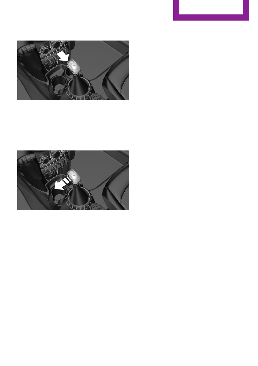
Canceling the lock
Press button on the front of the selector lever,
arrow.
Sport program and manual mode M/S
Activating the sport program
Press the selector lever to the left out of selec‐
tor lever position D.
The engaged gear is displayed in the instru‐
ment cluster, e.g., S1.
The sport program of the transmission is acti‐
vated.
Activating the M/S manual mode
1.
Press the selector lever to the left out of se‐
lector lever position D.
2. Push the selector lever forward or back‐
ward.
Manual mode becomes active and the gear is
changed.
The engaged gear is displayed in the instru‐
ment cluster, e.g., M1.
If the situation requires, the Steptronic trans‐
mission continues to shift automatically.
Example: once maximum engine speed is at‐
tained, M/S manual mode is automatically up‐
shifted as needed.
Switching to manual mode
▷ To shift down: press the selector lever for‐
ward.
▷ To shift up: pull the selector lever rear‐
wards.
Gears will only be shifted at appropriate engine
and road speeds, for example downshifting is
not possible if the engine speed is too high.
The selected gear is briefly displayed in the in‐
strument cluster, followed by the currently se‐
lected gear.
Manual mode M/S: prevent automatic
upshifting
Once a particular engine speed is attained, M/S
manual mode is automatically upshifted as
needed.
For vehicles with Steptronic Sport transmission,
automatic shift operations are not performed if
one of the following conditions is met:
▷ DSC is deactivated.
▷ TRACTION is activated.
In addition, there is no downshift for kickdown.
With the respective transmission version, the
lowest possible gear can be selected by simul‐
taneously operating the kickdown and the left
shift paddle. However, this effect is not pro‐
duced via the shift paddles when switching
briefly from D to manual mode.
Ending the sport program/manual
mode
Push the selector lever to the right.
D is displayed in the instrument cluster.
Seite 59
Driving
CONTROLS
59
Online Edition for Part no. 01 40 2 963 307 - VI/15
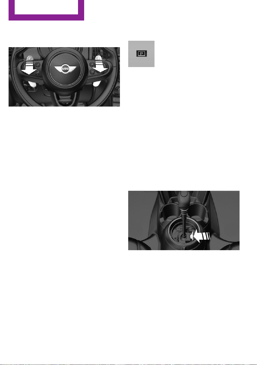
Shift paddles for Steptronic Sport
transmission
The shift paddles on the steering wheel allow
you to shift gears quickly while keeping both
hands on the steering wheel.
▷ Shift up: briefly pull right shift paddle.
▷ Shift down: briefly pull left shift paddle.
▷ With the respective transmission version,
the lowest possible gear can be selected by
pulling and holding the left shift paddle.
Gears will only be shifted at appropriate engine
and road speeds, for example downshifting is
not possible if the engine speed is too high.
The selected gear is briefly displayed in the in‐
strument cluster, followed by the current gear.
If the shift paddles on the steering wheel are
used to shift gears in automatic mode, the
transmission temporarily switches to manual
mode.
If the selector lever is still in selector lever posi‐
tion D with the respective transmission version,
it is possible to switch back into the automatic
mode:
▷ Pull and hold right shift paddle.
or
▷ In addition to the briefly pulled right shift
paddle, briefly pull the left shift paddle.
In the manual mode, after conservative driving
for a certain amount of time or if there has
been no acceleration or shifting of the shift
paddles within a certain amount of time, the
transmission switches back to automatic mode.
Displays in the instrument cluster
The selector lever position is dis‐
played, e.g.: P.
Manually release the transmission lock
Should the selector lever be blocked in selector
lever position P despite the ignition being
turned on, the brake being depressed and the
unlock button being pressed, the transmission
lock can be manually canceled:
Before unlocking the transmission lock man‐
ually, engage the parking brake forcefully to
prevent the vehicle from rolling away.
1.
Loosen the sleeve of the selector lever.
2. Pull the sleeve over the selector lever. Un‐
plug the cable connector if needed.
3. Using the screwdriver from the onboard ve‐
hicle tool kit, refer to page 202, press the
yellow release lever downward, arrow.
4. Move the selector lever slightly toward the
rear; to do this press the unlock button on
the front of the selector lever.
Release the release lever.
5. Bring the selector lever into the desired po‐
sition.
Seite 60
CONTROLS
Driving
60
Online Edition for Part no. 01 40 2 963 307 - VI/15

Steptronic Sport transmission: Launch
Control
The concept
Launch Control enables optimum acceleration
on surfaces with good traction.
General information
The use of Launch Control causes premature
component wear since this function represents
a very heavy load for the vehicle.
Do not use Launch Control during the break-in,
refer to page 136, period.
To increase vehicle stability, activate DSC again
as soon as possible.
An experienced driver may be able to achieve
better acceleration values in DSC OFF mode, re‐
fer to page 97.
Requirements
Launch Control is available when the engine is
warmed up, that is, after uninterrupted driving
of at least 6 miles/10 km.
To start with Launch Control do not steer the
steering wheel.
Start with launch control
While the engine is running:
1. Press button and select SPORT with
Driving Dynamics Control, refer to
page 99.
The instrument cluster displays TRACTION
in combination with SPORT. The DSC OFF
indicator lamp lights up.
2. Engage selector lever position S.
3. With the left foot, forcefully press down on
the brake.
4. Step on the accelerator pedal beyond the
resistance point at the full throttle position,
kickdown.
A flag symbol is displayed in the instrument
cluster.
5. The starting engine speed adjusts. Within
3 seconds, release the brake.
Before using Launch Control, allow the trans‐
mission to cool down for approx. 5 minutes.
Seite 61
Driving
CONTROLS
61
Online Edition for Part no. 01 40 2 963 307 - VI/15
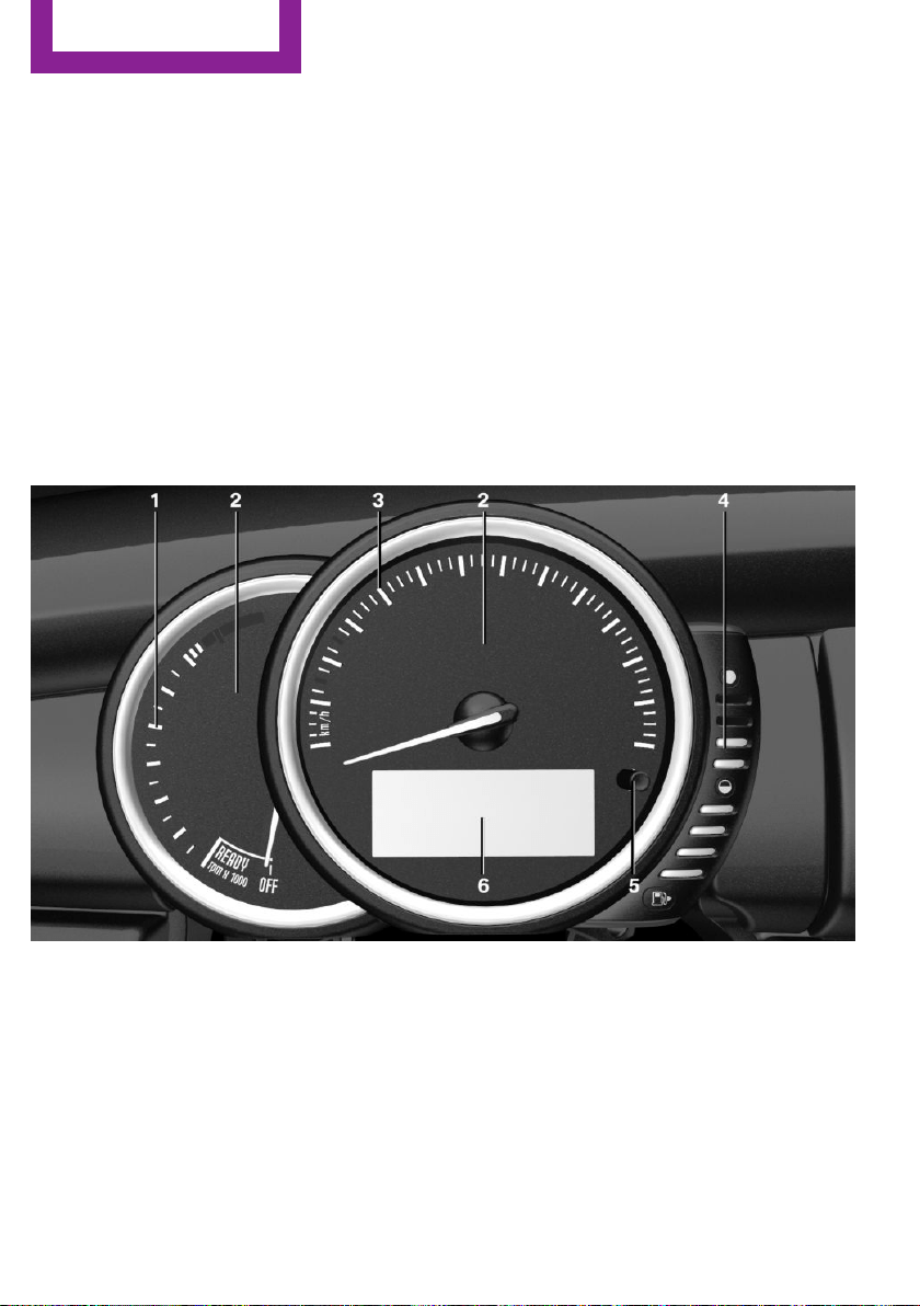
Displays
Vehicle features and op‐
tions
This chapter describes all standard, country-
specific and optional features offered with the
series. It also describes features that are not
necessarily available in your car, e. g., due to
the selected options or country versions. This
also applies to safety-related functions and sys‐
tems. The respectively applicable country provi‐
sions must be observed when using the respec‐
tive features and systems.
Instrument cluster
Overview, instrument cluster
1 Tachometer 67
2 Messages, e.g. Check Control
3 Speedometer
4 Fuel gauge 67
5 Display/reset miles 67
6 Electronic displays 63
Seite 62
CONTROLS
Displays
62
Online Edition for Part no. 01 40 2 963 307 - VI/15
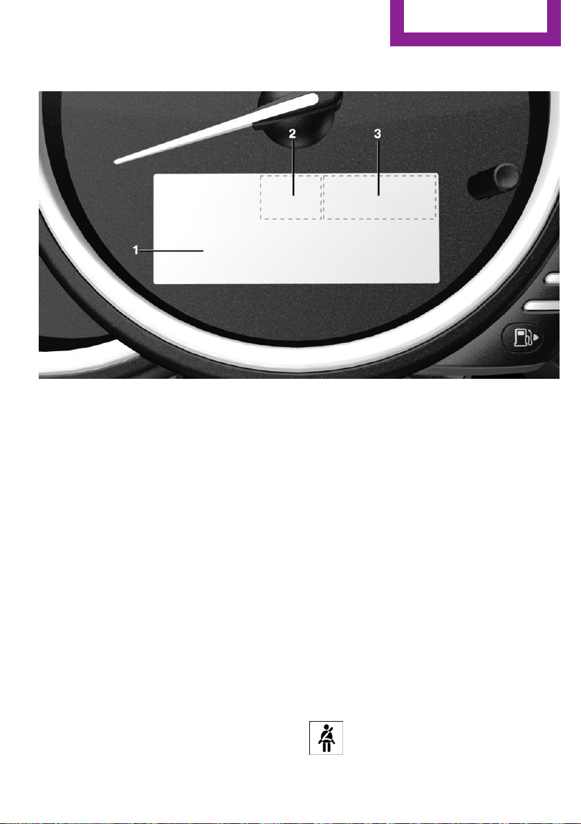
Electronic displays
1 Driver assistance systems
Messages, e.g. Check Control
Time 67
External temperature 67
Selection lists 70
Total miles/trip odometer 67
On-board computer 71
2 Selector lever position display 58
Gear shift indicator 68
3 Driving Dynamics Control 99
Status
Check Control
The concept
The Check Control system monitors functions in
the vehicle and notifies you of malfunctions in
the monitored systems.
A Check Control message is displayed as a com‐
bination of indicator or warning lights and text
messages in the instrument cluster.
In addition, an acoustic signal may be output
and a text message may appear on the radio.
Indicator/warning lights
General information
The indicator and warning lights can light up in
a variety of combinations and colors.
Several of the lights are checked for proper
functioning and light up temporarily when the
engine is started or the ignition is switched on.
Red lights
Safety belt reminder
Flashing or illuminated: safety belt on
the driver or passenger side is not buck‐
led. The safety belt reminder can also
Seite 63
Displays
CONTROLS
63
Online Edition for Part no. 01 40 2 963 307 - VI/15
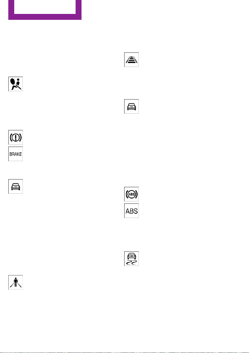
be activated if objects are placed on the front
passenger seat.
Make sure that the safety belts are positioned
correctly.
Airbag system
Airbag system and belt tensioner are
not working.
Have the vehicle checked immediately
by a dealer’s service center or another qualified
service center or repair shop.
Parking brake, brake system
The parking brake is set.
For additional information, refer to Re‐
lease parking brake, refer to page 54.
Front-end collision warning
Illuminated: advance warning is issued,
e.g., when there is the impending dan‐
ger of a collision or the distance to the
vehicle ahead is too small.
Increase distance.
Flashing: acute warning of the imminent dan‐
ger of a collision when the vehicle approaches
another vehicle at a relatively high differential
speed.
Intervention by braking or make an evasive
maneuver.
Pedestrian warning
If a collision with a person detected in
this way is imminent, the symbol lights
up and a signal sounds.
Orange lights
Active Cruise Control
The number bars shows the selected
distance from the vehicle driving ahead.
For more information, see Camera-
based cruise control, refer to page 101.
Vehicle detection, Active Cruise Control
Illuminated: vehicle driving ahead de‐
tected.
Flashing: the conditions are not ade‐
quate for operating the system.
The system was deactivated but applies the
brakes until you actively resume control by
pressing on the brake pedal or accelerator
pedal.
Yellow lights
Anti-lock Braking System ABS
Avoid sudden braking as much as possi‐
ble. Braking force boost may not be
working. Stop cautiously. Take into ac‐
count the longer brake distance. Have
checked immediately by a dealer’s
service center or another qualified serv‐
ice center or repair shop.
DSC Dynamic Stability Control
Flashing: DSC controls the drive and
braking forces. The vehicle is stabilized.
Reduce speed and adapt driving style to
the driving circumstances.
Illuminated: DSC failed. Have system checked
immediately by a dealer’s service center or an‐
other qualified service center or repair shop.
For additional information, refer to Dynamic
Stability Control DSC, refer to page 97.
Seite 64
CONTROLS
Displays
64
Online Edition for Part no. 01 40 2 963 307 - VI/15

DSC Dynamic Stability Control is deactivated
or DTC Dynamic Traction Control is activated
Dynamic Stability Control DSC is
switched off or Dynamic Traction Con‐
trol DTC is switched on.
For additional information, refer to Dynamic
Stability Control DSC, refer to page 97, and
Dynamic Traction Control DTC, refer to
page 98.
Flat Tire Monitor FTM
The Flat Tire Monitor signals a loss of
tire inflation pressure in a tire.
Reduce your speed and stop cautiously.
Avoid sudden braking and steering maneuvers.
For additional information, refer to Flat Tire
Monitor, refer to page 88.
Tire Pressure Monitor TPM
Illuminated: the Tire Pressure Monitor
signals a loss of tire inflation pressure in
a tire.
Reduce your speed and stop cautiously. Avoid
sudden braking and steering maneuvers.
Flashing and then continuously illuminated: no
flat tire or loss of tire inflation pressure can be
detected.
▷ Interference through systems or devices
with the same radio frequency: After leav‐
ing the area of the interference, the system
automatically becomes active again.
▷ TPM could not conclude the reset: perform
the reset of the system again.
▷ A wheel without TPM electronics is
mounted: Have it checked by a dealer’s
service center or another qualified service
center or repair shop as needed.
▷ Malfunction: Have system checked by a
dealer’s service center or another qualified
service center or repair shop.
For additional information, refer to Tire Pres‐
sure Monitor, refer to page 84.
Steering system
Steering system in some cases not
working.
Have steering system checked immedi‐
ately by a dealer’s service center or another
qualified service center or repair shop.
Engine functions
Have vehicle checked immediately by a
dealer’s service center or another quali‐
fied service center or repair shop.
For additional information, refer to On-board
Diagnostics socket, refer to page 201.
Green lights
Turn signal
Turn signal switched on.
Unusually rapid flashing of the indicator
lamp indicates that a turn signal bulb
has failed.
For additional information, refer to Turn signal,
refer to page 54.
Parking lights, headlight control
Parking lights or headlights are acti‐
vated.
For additional information, refer to
Parking lights/low beams, headlight control, re‐
fer to page 76.
Front fog lights
Front fog lights are activated.
For additional information, refer to
Front fog lights, refer to page 79.
Seite 65
Displays
CONTROLS
65
Online Edition for Part no. 01 40 2 963 307 - VI/15
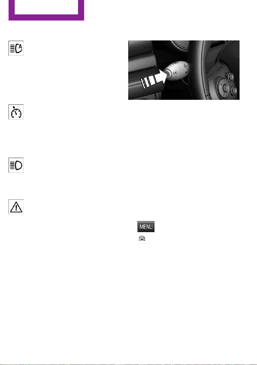
High-beam Assistant
High-beam Assistant is switched on.
High beams are activated and off auto‐
matically as a function of the traffic sit‐
uation.
For additional information, refer to High-beam
Assistant, refer to page 78.
Cruise control
The system is switched on. It maintains
the speed that was set using the control
elements on the steering wheel.
Blue lights
High beams
High beams are activated.
For additional information, refer to High
beams, refer to page 54.
General lamps
At least one Check Control message is
displayed or is stored.
Text messages
Text messages in combination with a symbol in
the instrument cluster explain a Check Control
message and the meaning of the indicator and
warning lights.
Supplementary text messages
Additional information, such as on the cause of
an error or the required action, can be called up
via Check Control.
With urgent messages the added text will be
automatically displayed on the radio display.
To view the entire text line for line: turn the
right-hand knob on the radio.
Hiding Check Control messages
Press and hold PC button on blinker lever.
▷ Some Check Control messages are dis‐
played continuously and are not cleared
until the malfunction is eliminated. If sev‐
eral malfunctions occur at once, the mes‐
sages are displayed consecutively.
These messages can be faded for approx.
8 seconds. After this time, they are dis‐
played again automatically.
▷ Other Check Control messages are faded
automatically after approx. 20 seconds.
They are stored and can be displayed again
later.
Displaying stored Check Control
messages
1. Press button.
2. "Vehicle Info"
3. "Vehicle status"
4. "Check Control"
5. Selecting the desired Check Control mes‐
sage
Messages after trip completion
Special messages displayed while driving are
displayed again after the ignition is switched
off.
Seite 66
CONTROLS
Displays
66
Online Edition for Part no. 01 40 2 963 307 - VI/15
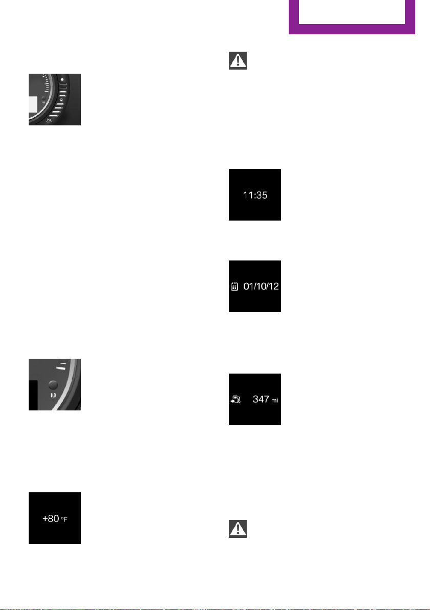
Fuel gauge
Vehicle tilt position may cause
the display to vary.
The arrow beside the fuel pump
symbol shows which side of the
vehicle the fuel filler flap is on.
Hints on refueling, refer to page 174.
Tachometer
Always avoid engine speeds in the red warning
field. In this range, the fuel supply is interrupted
to protect the engine.
Odometer and trip odom‐
eter
The concept
Odometer and trip odometer are displayed in
the instrument cluster.
Resetting the trip odometer
Press the knob.
▷ The odometer is displayed
when the ignition is switched
off.
▷ When the ignition is switched
on, the trip odometer is re‐
set.
External temperature
If the indicator drops to
+37 ℉/+3 ℃, a signal sounds.
A Check Control message is dis‐
played.
There is an increased risk of ice
on roads.
WARNING
Even at temperatures above +37 ℉/+3 ℃
there can be a danger of icy roads, e.g. on
bridges or shady sections of road. There is risk
of an accident. Adjust your driving style to the
weather conditions at low temperatures.◀
Time
The time is displayed in the in‐
strument cluster.
Setting the time on the radio, re‐
fer to page 73.
Date
The date is displayed in the in‐
strument cluster.
Set the date on the radio, refer
to page 73.
Range
Display
With a low remaining range:
▷ A Check Control message is
displayed briefly.
▷ The remaining range is
shown on the onboard com‐
puter.
▷ With a dynamic driving style, e.g. taking
curves aggressively, the engine function is
not always ensured.
The Check Control message appears continu‐
ously below a range of approx. 30 miles/50 km.
CAUTION
With a range of less than 30 miles/50 km
it is possible that the engine will no longer have
sufficient fuel. Engine functions are no longer
Seite 67
Displays
CONTROLS
67
Online Edition for Part no. 01 40 2 963 307 - VI/15
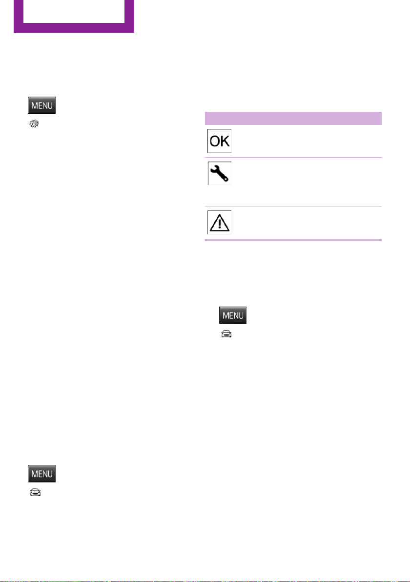
ensured. There is risk of property damage. Re‐
fuel promptly.◀
Displaying the cruising range
1.
Press button.
2. "Settings"
3. "Instrument cluster display"
4. "Range"
Current fuel consump‐
tion
The concept
Displays the current fuel consumption. Check
whether you are currently driving in an efficient
and environmentally-friendly manner.
Service requirements
The concept
After the ignition is turned on the instrument
cluster briefly displays available driving distance
or time to the next scheduled maintenance.
A service advisor can read out the current serv‐
ice requirements from your remote control.
Display
Detailed information on service
requirements
The radio will display detailed information
about service requirements.
1. Press button.
2. "Vehicle Info"
3. "Vehicle status"
4. "Service required"
5. Select the desired entry to view detailed in‐
formation.
Symbols
Symbols Description
No service is currently required.
The deadline for scheduled
maintenance or a legally man‐
dated inspection is approach‐
ing.
The service deadline has al‐
ready passed.
Entering appointment dates
Enter the dates for the required inspections.
Make sure that the vehicle's date and time are
set correctly.
1. Press button.
2. "Vehicle Info"
3. "Vehicle status"
4. "Service required"
5. "§ Vehicle inspection" or "§ Emission
inspection"
6. "Change date"
7. Enter the desired appointment.
Gear shift indicator
The concept
The system recommends the most fuel efficient
gear for the current driving situation.
General information
Depending on the vehicle's features and coun‐
try version of the vehicle, the gear shift indica‐
Seite 68
CONTROLS
Displays
68
Online Edition for Part no. 01 40 2 963 307 - VI/15
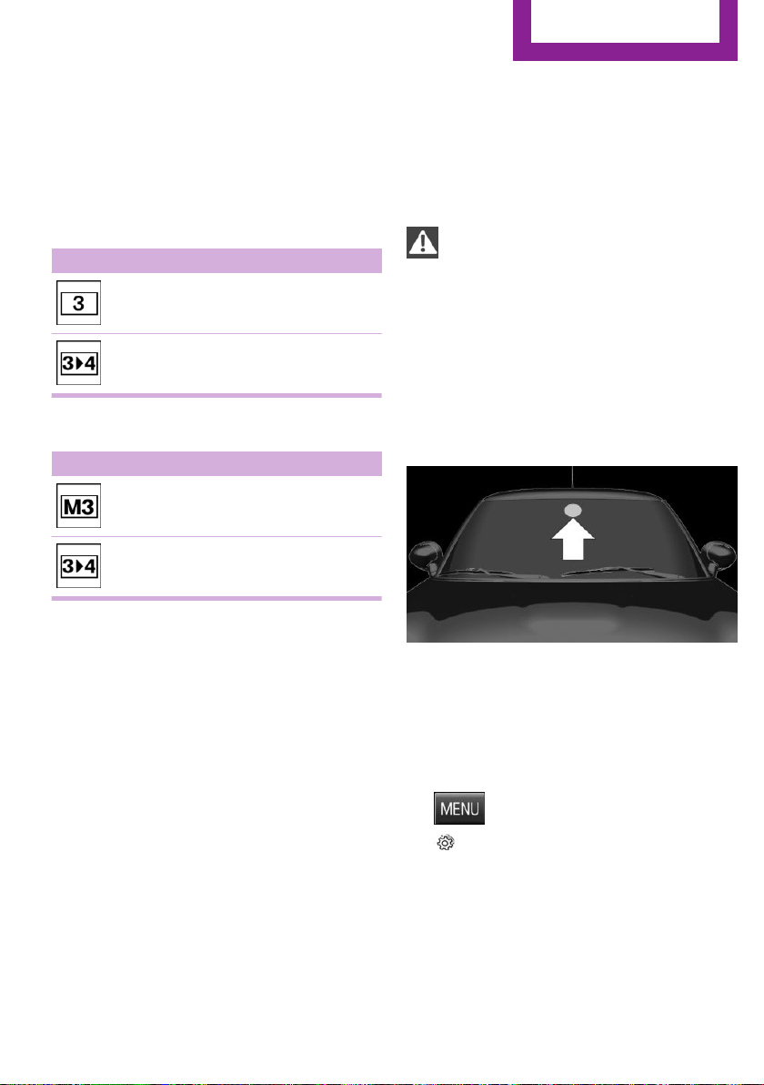
tor is active in the manual mode of the Step‐
tronic transmission and with manual
transmission.
Suggestions to shift gear up or down are dis‐
played in the instrument cluster.
Manual transmission: displaying
Example Description
Fuel efficient gear is set.
Shift into fuel efficient gear.
Steptronic transmission: displaying
Example Description
Fuel efficient gear is set.
Shift into fuel efficient gear.
Speed limit detection
The concept
Speed limit detection
Speed limit detection shows the current maxi‐
mum permitted speed in the instrument clus‐
ter. The camera at the base of the interior rear‐
view mirror detects traffic signs at the edge of
the road as well as variable overhead sign
posts. Traffic signs with extra symbols for wet
road conditions, etc. are also detected and
compared with the vehicle's onboard data,
such as for the rain sensor, and will be dis‐
played depending on the situation.
Without a navigation system, the system is sub‐
ject to limitations imposed by technology.
Speed limits with extra text characters are al‐
ways displayed.
Information
Speed limits when towing a trailer are not
shown.
WARNING
The system does not relieve from the per‐
sonal responsibility to correctly assess visibility
and traffic situation. There is risk of an accident.
Adjust the driving style to the traffic conditions.
Watch traffic closely and actively interfere in
the respective situations.◀
Overview
Camera
The camera is installed near the interior rear‐
view mirror.
Keep the windshield in the area behind the in‐
terior rearview mirror clean and clear.
Switching on/off
1. Press button.
2. "Settings"
3. "Instrument cluster display"
4. "Speed limit information"
If speed limit detection is switched on, it can be
displayed on the info display in the instrument
cluster via the on-board comupter.
Seite 69
Displays
CONTROLS
69
Online Edition for Part no. 01 40 2 963 307 - VI/15
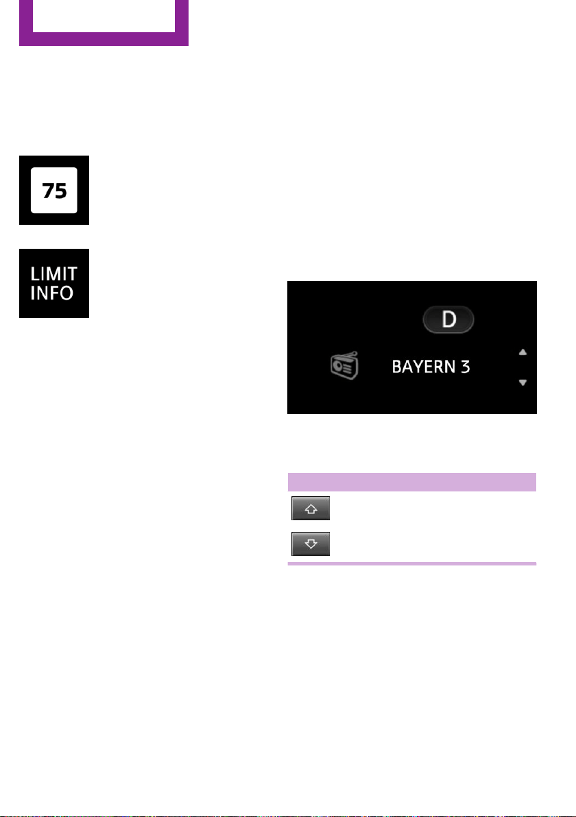
Display
The following is displayed in the instrument
cluster:
Speed limit detection
The last speed limit detected.
Without a navigation system the
traffic signals are grayed out af‐
ter curves or longer stretches of
roadway.
Without navigation system:
speed limit detection switched
on but no speed limit or cancel‐
lation is detected.
System limits
The system may not be fully functional and
may provide incorrect information in the fol‐
lowing situations:
▷ In heavy fog, rain or snowfall.
▷ When signs are concealed by objects.
▷ When driving very close to the vehicle in
front of you.
▷ When driving toward bright lights.
▷ When the windshield behind the interior
rearview mirror is fogged over, dirty or cov‐
ered by a sticker, etc.
▷ In the event of incorrect detection by the
camera.
▷ When passing buses or trucks with a speed
sticker.
▷ If the traffic signs are non-conforming.
▷ During calibration of the camera immedi‐
ately after vehicle delivery.
Selection lists in the in‐
strument cluster
The concept
With the buttons on the steering wheel and the
display in the instrument cluster the following
can be displayed or operated:
▷ Current audio source.
It also displays programs of the Driving Dynam‐
ics Control.
Display
Activating a list and adjusting the
setting
Button the steering wheel Function
Activate the respec‐
tive list and select the
desired settings.
Seite 70
CONTROLS
Displays
70
Online Edition for Part no. 01 40 2 963 307 - VI/15
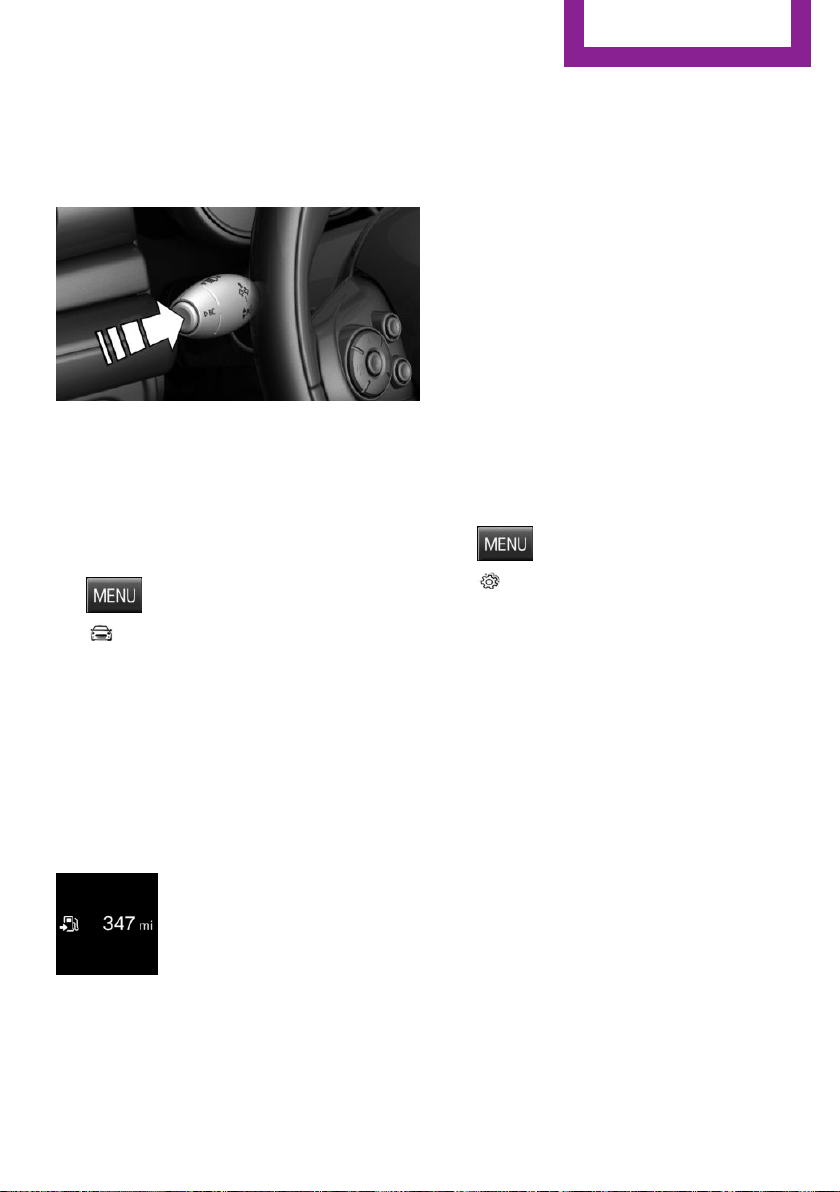
On-board computer
Calling up information on the info
display
Press and hold PC button on blinker lever.
Information is displayed in the info display of
the instrument cluster.
Calling up information in the radio
Information is also shown on the radio display.
1. Press button.
2. "Vehicle Info"
3. "Onboard info"
Resetting values
1.
Select the desired value.
2. "Reset?"
Information at a glance
Info display
Repeatedly pressing the button
on the turn signal lever calls up
the following information in the
info display:
▷ Range.
▷ GREEN Info.
When GREEN Mode is activated.
▷ Average fuel consumption.
▷ Current fuel consumption.
▷ Average speed.
▷ Date.
▷ Engine temperature display.
▷ Speed limit detection.
▷ Speed.
Radio
Selected information is shown on the radio.
▷ Range.
▷ Average fuel consumption.
▷ Average speed.
Adjusting the info display
You can select what information from the on-
board comupter is to be displayed on the info
display of the instrument cluster.
1. Press button.
2. "Settings"
3. "Instrument cluster display"
4. Select the desired displays.
Information in detail
Range
Displays the estimated cruising range available
with the remaining fuel.
It is calculated based on your driving style over
the last 20 miles/30 km.
GREEN info
Description of GREEN info, refer to page 144.
Average fuel consumption
This is calculated for the period while the en‐
gine is running.
The average fuel consumption is calculated for
the distance traveled since the last reset by the
on-board comupter.
Seite 71
Displays
CONTROLS
71
Online Edition for Part no. 01 40 2 963 307 - VI/15
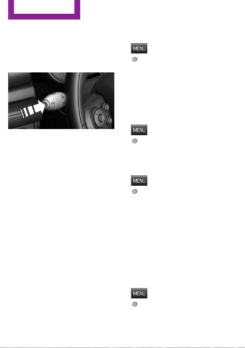
Average speed
Periods in which the vehicle is parked with the
engine manually stopped are not included in
the calculation of the average speed.
Resetting average values
Press and hold PC button on blinker lever.
Engine temperature display
Displays the current engine temperature, based
on a combination of coolant and motor oil tem‐
perature. As soon as the optimum operating
temperature has been attained, the indicator is
in the center position.
If the engine oil or coolant, thus the engine, be‐
come too hot, a Check Control message is dis‐
played.
Check the coolant level, refer to page 198.
Speed limit detection
Description of the speed limit detection, refer
to page 69, function.
Speed warning
The concept
Displays speed limit which, when reached,
should cause a warning to be issued.
The warning is repeated if the vehicle speed
drops below the set speed limit once by at least
3 mph/5 km/h.
Displaying, setting or changing the
limit
1.
Press button.
2. "Settings"
3. "Speed"
4. "Warning at:"
5. Turn the right knob until the desired limit is
displayed.
6. Press the right button.
The speed limit is stored.
Activating/deactivating the limit
1. Press button.
2. "Settings"
3. "Speed"
4. "Warning"
Setting your current speed as the limit
1. Press button.
2. "Settings"
3. "Speed"
4. "Select current speed"
The current vehicle speed is stored as the
limit.
Settings on the radio
The following settings are created on the radio:
▷ Time, date.
▷ Formats, units of measure.
Formats and units of measure
1. Press button.
2. "Settings"
3. "Language/Units"
Seite 72
CONTROLS
Displays
72
Online Edition for Part no. 01 40 2 963 307 - VI/15
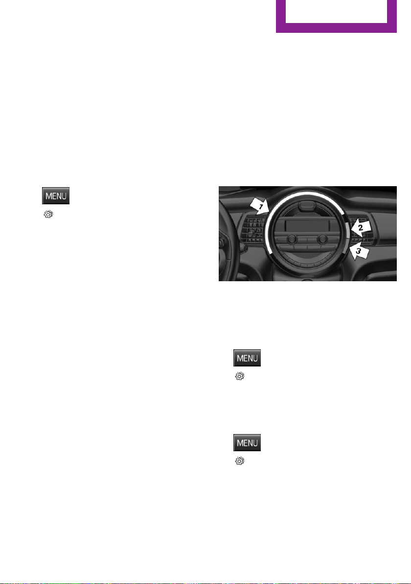
4. Select the desired format or unit of meas‐
ure:
▷ "Language:"
▷ "Consumption:"
▷ "Distance:"
▷ "Pressure:"
▷ "Temperature:"
5. Set the desired unit of measure or lan‐
guage.
Setting the time and date
1. Press button.
2. "Settings"
3. "Time/Date"
4. Select desired menu entry:
▷ "Time:"
▷ "Time format:"
▷ "Date:"
▷ "Date format:"
5. Turn the right knob until the desired setting
is selected.
LED ring on the central
instrument cluster
The concept
The LED ring displays light animations to repre‐
sent specific functions.
Basic displays
Basic functions, for example the tachometer,
can be set to be displayed continually if so de‐
sired.
Event displays
Functions that are only displayed temporarily,
for example the volume or temperature set‐
tings, can be set as event displays.
Several vehicle assistance functions can also be
displayed on the LED ring. This display corre‐
sponds with the displays of the function in the
respective display.
Example: tachometer
Like the tachometer in the instrument cluster,
the light animations of the tachometer's basic
display show the current RPMs and the respec‐
tive RPM warning margins.
Display
▷ Arrow 1: current RPM.
▷ Arrow 2: prewarning field.
▷ Arrow 3: warning field.
Switching on/off LED ring
1. Press button.
2. "Settings"
3. "Center Instrument"
4. "Center Instrument"
Adjusting the LED ring
1. Press button.
2. "Settings"
3. "Center Instrument"
4. "Basic display" or "Event display"
5. Select desired setting.
Seite 73
Displays
CONTROLS
73
Online Edition for Part no. 01 40 2 963 307 - VI/15
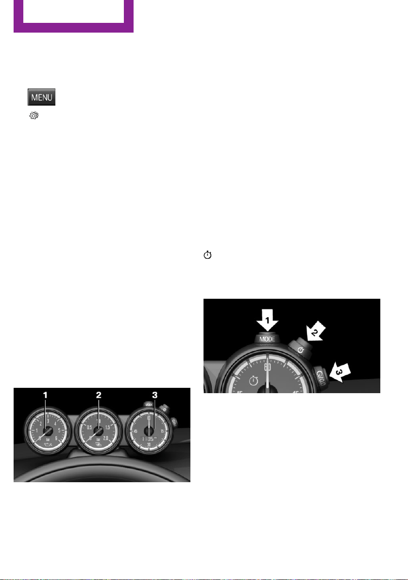
Setting the brightness
The brightness can be adjusted when night
lighting is active in the instrument cluster.
1.
Press button.
2. "Settings"
3. "Center Instrument"
4. "Brightness"
5. Turn the right-hand knob.
Settings are stored for the profile currently
used.
Chrono package in the
cockpit
The concept
The Chrono package consists of three display
instruments in the cockpit, where the engine oil
pressure, the turbocharger boost, and the time
are displayed. In addition, intermediate and to‐
tal times can be measured using the stop
watch.
The display elements of the Chrono package
mainly support a sporty driving style, e,g, on
racetracks.
Overview
1 Engine oil pressure display
2 Display of turbocharger boost
3 Time/stop watch
Engine oil pressure
The current engine oil pressure is displayed. At
low temperatures, there can be an increase in
the engine oil pressure.
Turbocharger boost
The current boost of the engine's turbocharger
is displayed.
Stop watch
General information
The stop watch contains the following features:
▷ Measuring the total time.
▷ Measuring and storing of up to nine lap
times.
▷ Displaying the time.
The red indicator light indicates that the
stop watch is active.
Overview, buttons
▷ MODE button, arrow 1.
▷ START/STOP button, arrow 2.
▷ RESET/LAP buttons, arrow 3.
Displaying the measured times
The times measured using the stop watch are
shown in minutes and seconds on the display.
For times greater than 60 minutes, the num‐
bers of hours and the minutes with seconds are
alternatively displayed.
Seite 74
CONTROLS
Displays
74
Online Edition for Part no. 01 40 2 963 307 - VI/15

If the stop watch is running, the seconds are
also shown using a seconds pointer in the scale
of the display element.
Measuring the total time
1. Press button, arrow 2, to start the stop
watch.
2. Press button, arrow 2, again to stop the
stop watch.
Lap times
General information
It is possible to measure and store up to nine
lap times. Older lap times are overwritten.
Measuring and storing a lap time
1.
Press button, arrow 2, to start the stop
watch.
2. Press button, arrow 3, to measure and store
a lap time.
The lap time is briefly shown in the display
and via the seconds pointer of the stop
watch, e.g., LAP 1 with the measured time.
The stop watch continues running in the
background.
3. If needed, press button, arrow 3, again to
measure a further lap time.
Calling up lap times
1.
Press button, arrow 1, repeatedly until
LAP 1 is shown on the display.
2. Press button, arrow 2, to call up the individ‐
ual lap times.
Deleting lap times
1.
Press button, arrow 1, repeatedly until
LAP 1 is shown on the display.
2. Press button, arrow 3, to delete all stored
lap times.
Displaying the time
The time is copied from the instrument cluster.
Press button, arrow 1, repeatedly until the time
is displayed.
Seite 75
Displays
CONTROLS
75
Online Edition for Part no. 01 40 2 963 307 - VI/15

Lights
Vehicle features and op‐
tions
This chapter describes all standard, country-
specific and optional features offered with the
series. It also describes features that are not
necessarily available in your car, e. g., due to
the selected options or country versions. This
also applies to safety-related functions and sys‐
tems. The respectively applicable country provi‐
sions must be observed when using the respec‐
tive features and systems.
Overview
Switches in the vehicle
The light switch elements is located next to the
steering wheel.
Light functions
Symbol Function
Rear fog lights
Front fog lights
Automatic headlight control
Symbol Function
Lights off
Daytime running lights
Parking lights
Low beams
Instrument lighting
Parking lights, corner‐
ing lights and roadside
parking lights
General information
Position of switch: , ,
If the driver door is opened with the ignition
switched off, the exterior lighting is automati‐
cally switched off at these switch settings.
Parking lights
Position of switch:
The vehicle is illuminated on all sides.
Do not use the parking lights for extended peri‐
ods; otherwise, the battery may become dis‐
charged and it would then be impossible to
start the engine.
When parking, switch on the one-sided road‐
side parking lamp, refer to page 77.
Low beams
Position of switch:
The low beams light up when the ignition is
switched on.
Seite 76
CONTROLS
Lights
76
Online Edition for Part no. 01 40 2 963 307 - VI/15
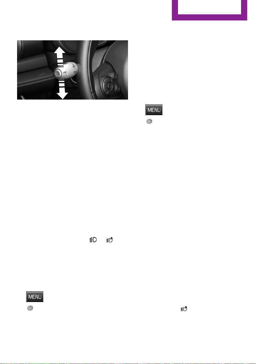
Roadside parking lights
The vehicle can be illuminated on one side.
Switching on
With the ignition switched off, press the lever
either up or down past the resistance point for
approx. 2 seconds.
Switch off
Briefly press the lever to the resistance point in
the opposite direction.
Welcome lights and
headlight courtesy de‐
lay feature
Welcome lights
Depending on the equipment, when switching
off the vehicle, switch position or .
The parking, low beam and interior lights light
up briefly when unlocking the vehicle or de‐
pending on the ambient brightness.
Activating/deactivating
Set via radio.
1. Press button.
2. "Settings"
3. "Lighting"
4. "Welcome light"
Settings are stored for the profile currently
used.
Headlight courtesy delay feature
The low beams stay lit for a short while if the
headlight flasher is switched on after the vehi‐
cle's radio-ready state is switched off.
Setting the duration
Set via radio.
1.
Press button.
2. "Settings"
3. "Lighting"
4. "Pathway lighting:"
5. Set length of time.
Settings are stored for the profile currently
used.
Automatic headlight
control
The concept
The low beams are switched on and off auto‐
matically depending on the ambient bright‐
ness, e.g. in tunnels, in twilight or if there is
precipitation.
General information
A blue sky with the sun low on the horizon can
cause the lights to be switched on.
When emerging from a tunnel during the day,
the low beams are not switched off immedi‐
ately but instead only after approx. 2 minutes.
Activating
Position of switch:
The indicator lamp in the instrument cluster
lights up when the low beams are switched on.
Seite 77
Lights
CONTROLS
77
Online Edition for Part no. 01 40 2 963 307 - VI/15
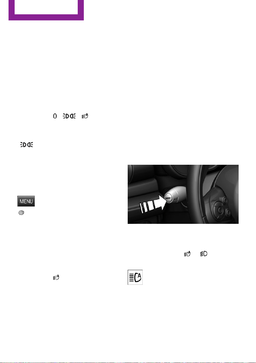
System limits
The automatic headlamp control cannot serve
as a substitute for your personal judgment of
lighting conditions.
E. g. the sensors are unable to detect fog or
hazy weather. To avoid safety risks under these
conditions, you should always switch on the
lights manually.
Daytime running lights
Position of switch:
, ,
The daytime running lights light up when the
ignition is switched on. After the ignition is
switched off, the parking lights light up in posi‐
tion .
Activating/deactivating
In some countries, daytime running lights are
mandatory, so it may not be possible to deacti‐
vate the daytime running lights.
Set via radio.
1. Press button.
2. "Settings"
3. "Lighting"
4. "Daytime running lamps"
Settings are stored for the profile currently
used.
Cornering lamp
Position of switch:
When going around corners, the cornering light
also lights the interior area of the curve. Below
a speed of approx. 25 mph/40 km/h when the
turn signal is switched on and the steering an‐
gle is detected, there is automatic activation.
Malfunction
A Check Control message is displayed.
Cornering light is disrupted or failed. Have the
system checked as soon as possible.
High-beam Assistant
The concept
When the low beams are activated, this system
automatically switches the high beams on and
off. The procedure is controlled by a camera on
the front of the interior rearview mirror. The as‐
sistant ensures that the high beams are acti‐
vated whenever the traffic situation allows. The
driver can intervene at any time and switch the
high beams on and off as usual. In the low
speed range, the high beams are not switched
on by the system.
Activating
The High-beam Assistant can be activated
when the low beams are activated.
1.
Depending on the equipment, turn the light
switch into position or .
2. Press button on the turn signal lever, arrow.
The indicator lamp in the instrument
cluster lights up.
When the low beams are on, the lights are au‐
tomatically brightened or dimmed.
The system responds to light from oncoming
traffic and traffic driving ahead of you, and to
adequate illumination, e.g., in towns and cities.
Seite 78
CONTROLS
Lights
78
Online Edition for Part no. 01 40 2 963 307 - VI/15
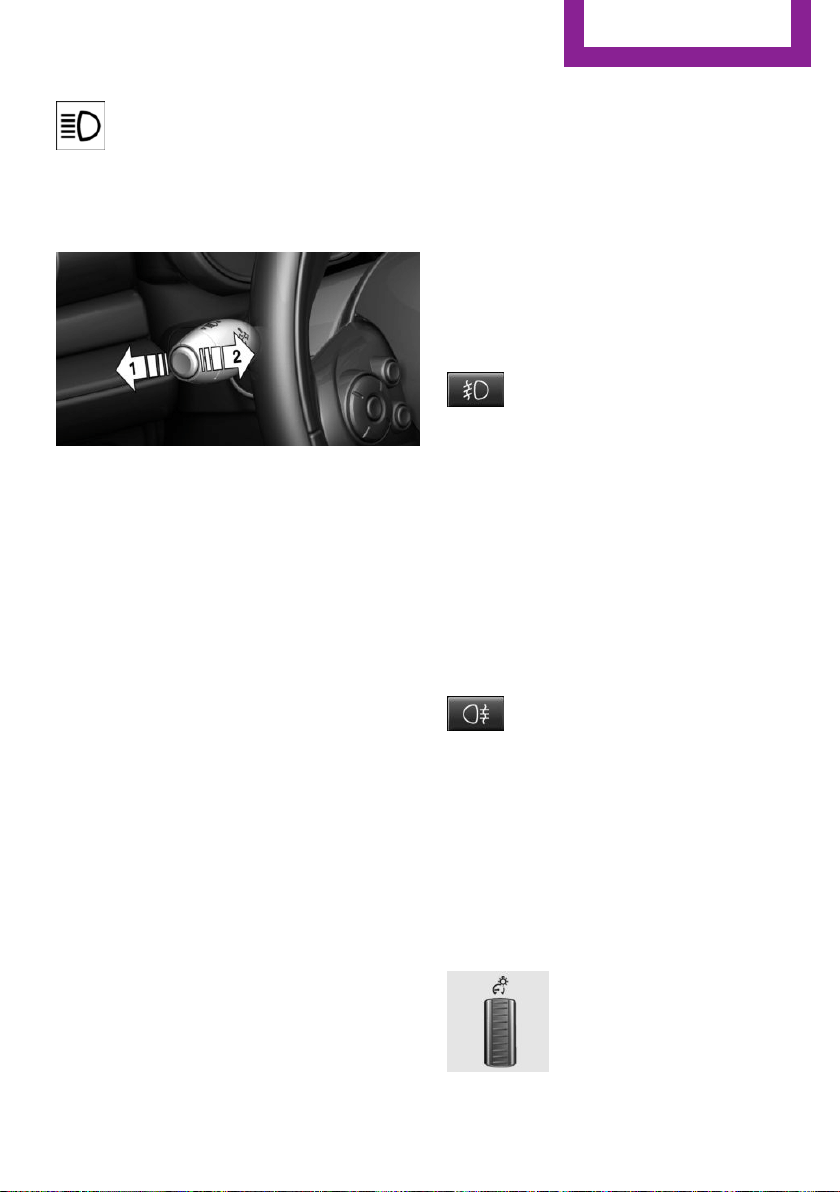
The blue indicator lamp in the instru‐
ment cluster lights up when the system
switches on the high beams.
Switching the high beams on and off
manually
▷ High beams on, arrow 1.
▷ High beams off/headlight flasher, arrow 2.
The High-beam Assistant can be switched off
when manually adjusting the light.
To reactivate the high-beam Assistant, press
the button on the turn signal lever, refer to
page 78.
System limits
The High-beam Assistant cannot serve as a
substitute for the driver's personal judgment of
when to use the high beams. Therefore, man‐
ually switch off the high beams in situations
where required to avoid a safety risk.
The system is not fully functional in situations
such as the following, and driver intervention
may be necessary:
▷ In very unfavorable weather conditions,
such as fog or heavy precipitation.
▷ When detecting poorly-lit road users such
as pedestrians, cyclists, horseback riders
and wagons; when driving close to train or
ship traffic; and at animal crossings.
▷ In tight curves, on hilltops or in depressions,
in cross traffic or half-obscured oncoming
traffic on freeways.
▷ In poorly-lit towns and cities and in the
presence of highly reflective signs.
▷ When the windshield behind the interior
rearview mirror is fogged over, dirty or cov‐
ered with stickers, etc.
Fog lights
Front fog lights
The low beams must be switched on.
Press button. The green indicator lamp
lights up.
If the automatic headlight control, refer to
page 77, is activated, the low beams will come
on automatically when you switch on the front
fog lights.
When the high beams or headlight flasher are
activated, the front fog lights are not switched
on.
Rear fog lights
The low beams or front fog lights must be
switched on.
Press button. The yellow indicator
lamp lights up.
If the automatic headlight control, refer to
page 77, is activated, the low beams will come
on automatically when you switch on the rear
fog lights.
Instrument lighting
Adjusting
The parking lights or low beams
must be switched on to adjust
the brightness.
Adjust the brightness with the
thumbwheel.
Seite 79
Lights
CONTROLS
79
Online Edition for Part no. 01 40 2 963 307 - VI/15
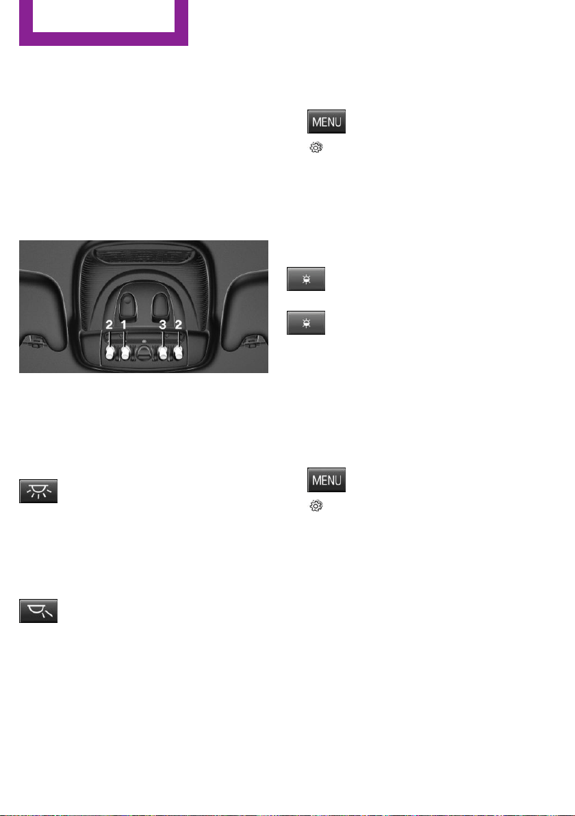
Interior lights
General information
The interior lights, footwell lights, access lights
and courtesy lights are controlled automati‐
cally.
Thumb wheel for the instrument lighting con‐
trols brightness of some of these features.
Overview
1 Interior lights
2 Reading lamp
3 Ambient light
Switching the interior lights on and off
Press button.
To switch off permanently: press the button for
approx. 3 seconds.
Switch back on: press button.
Reading lights
Press button.
Reading lights are located in the front next to
the interior light.
Ambient light
Depending on your optional features lighting
can be adjusted for some lights in the interior.
Activating/deactivating
Set via radio.
1.
Press button.
2. "Settings"
3. "Lighting"
4. "Ambient lighting"
Settings are stored for the profile currently
used.
Changing color
Push the switch forward or back:
manual color change.
Push and hold the switch forward or
back: automatic color change. Push
the switch again to end color changes.
Setting the brightness
Via the thumb wheel you may adjust the
brightness of the ambient light for the instru‐
ment lighting or radio.
Set via radio.
1. Press button.
2. "Settings"
3. "Lighting"
4. "Brightness"
5. Set the desired brightness.
Seite 80
CONTROLS
Lights
80
Online Edition for Part no. 01 40 2 963 307 - VI/15
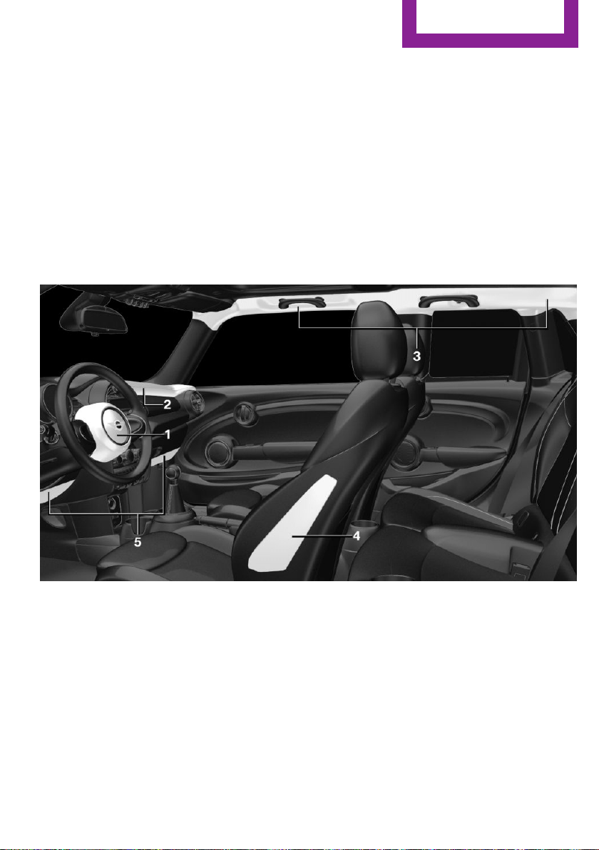
Safety
Vehicle features and op‐
tions
This chapter describes all standard, country-
specific and optional features offered with the
series. It also describes features that are not
necessarily available in your car, e. g., due to
the selected options or country versions. This
also applies to safety-related functions and sys‐
tems. The respectively applicable country provi‐
sions must be observed when using the respec‐
tive features and systems.
Airbags
1 Front airbag, driver
2 Front airbag, front passenger
3 Head airbag
4 Side airbag
5 Knee airbag
Front airbags
Front airbags help protect the driver and front
passenger by responding to frontal impacts in
which safety belts alone would not provide ad‐
equate restraint.
Side airbag
In a lateral impact, the side airbag supports the
side of the body in the chest and lap area.
Head airbag
In a lateral impact, the head airbag supports
the head.
Seite 81
Safety
CONTROLS
81
Online Edition for Part no. 01 40 2 963 307 - VI/15

Ejection Mitigation
The head airbag system is designed as an ejec‐
tion mitigation countermeasure to reduce the
likelihood of ejections of vehicle occupants
through side windows during rollovers or side
impact events.
Knee airbag
The knee airbag supports the legs in a frontal
impact.
Protective action
Airbags are not triggered in every impact situa‐
tion, e.g., in less severe accidents or rear-end
collisions.
Information for optimum effect of the
airbags
WARNING
If the seat position is incorrect or the de‐
ployment area of the airbags is impacted, the
airbag system cannot protect as intended or
cause additional injuries due to triggering.
There is risk of injuries or danger to life. Ob‐
serve the Information for optimum protective
effect of the airbag system.◀
▷ Keep at a distance from the airbags.
▷ Make sure that occupants keep their heads
away from the side airbag.
▷ Always grasp the steering wheel on the
steering wheel rim. Hold your hands at the
3 o'clock and 9 o'clock positions, to keep
the risk of injury to your hands or arms as
low as possible when the airbag is trig‐
gered.
▷ Make sure that the front passenger is sitting
correctly, i.e., keeps his or her feet and legs
in the floor area.
▷ There should be no persons, animals or ob‐
jects between an airbag and a person.
▷ Do not apply adhesive materials to the air‐
bag cover panels, do not cover them or
modify them in any way.
▷ Dashboard and windshield on the front
passenger side must stay clear - do not at‐
tach adhesive labels or coverings and do
not attach brackets or cables, e. g., for GPS
devices or' mobile phones.
▷ Do not use the cover of the front airbag on
the front passenger side as a storage area.
▷ Do not place slip covers, seat cushions or
other objects on the front passenger seat
that are not specifically suited for seats with
integrated side airbags.
▷ Do not hang pieces of clothing, such as
jackets, over the backrests.
▷ Never modify either the individual compo‐
nents or the wiring in the airbag system.
This also applies to steering wheel covers,
the dashboard, and the seats.
▷ Do not remove the airbag system.
Even when you follow all instructions very
closely, injury from contact with the airbags
cannot be ruled out in certain situations.
The ignition and inflation noise may lead to
short-term and, in most cases, temporary hear‐
ing impairment in sensitive individuals.
Warnings and information on the airbags are
also found on the sun visors.
Functional readiness of the airbag
system
Information
WARNING
Individual components can be hot after
triggering of the airbag system. There is risk of
injuries. Do not touch individual components.◀
WARNING
Improperly executed work can lead to
failure, malfunction or unintentional triggering
of the airbag system. In the case of a malfunc‐
Seite 82
CONTROLS
Safety
82
Online Edition for Part no. 01 40 2 963 307 - VI/15
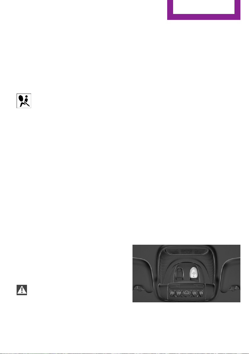
tion, the airbag system could not trigger as in‐
tended in the event of an accident despite re‐
spective accident severity. There is risk of
injuries or danger to life. Have the airbag sys‐
tem checked, repaired, dismantled and scrap‐
ped by a dealer’s service center or another
qualified service center or repair shop.◀
Correct function
When the ignition is switched on, the
warning lamp in the instrument cluster
lights up briefly and thereby indicates
the operational readiness of the entire airbag
system and the belt tensioner.
Airbag system malfunctioning
▷ Warning lamp does not come on when the
ignition is turned on.
▷ The warning lamp lights up continuously.
Automatic deactivation of the front-
seat passenger airbags
The concept
The system reads if the front passenger seat is
occupied by measuring the human body's re‐
sistance.
Front, knee and side airbag on the front pas‐
senger's side are either activated or deacti‐
vated.
Information
Before transporting a child on the front passen‐
ger seat, refer to the safety notes and instruc‐
tions for children on the front passenger seat,
see Children.
WARNING
The ensure the front-seat passenger air‐
bag function, it must be detected, whether a
person occupies the front passenger seat. The
entire seat cushion area must be used for this
purpose. There is risk of injuries or danger to
life. Make sure that the front passenger keeps
his or her feet in the floor area.◀
Malfunction of the automatic
deactivation system
When transporting older children and adults,
the front-seat passenger airbags may be deac‐
tivated in certain sitting positions. In this case,
the indicator lamp for the front-seat passenger
airbags lights up.
In this case, change the sitting position so that
the front-seat passenger airbags are activated
and the indicator lamp goes out.
If it is not possible to activate the airbags, have
the person sit in the rear.
To enable correct recognition of the occupied
seat cushion
▷ Do not attach covers, cushions, ball mats or
other items to the front passenger seat un‐
less they are specifically determined to be
safe for use on the front passenger seat.
▷ Do not place any electronic devices on the
passenger seat if a child restraint system is
to be installed on it.
▷ Do not place objects under the seat that
could press against the seat from below.
▷ No moisture in or on the seat.
Indicator lamp for the front-seat
passenger airbags
The indicator lamp for the front-seat passenger
airbags indicates the operating state of the
front-seat passenger airbags.
Seite 83
Safety
CONTROLS
83
Online Edition for Part no. 01 40 2 963 307 - VI/15

The lamp indicates whether the airbags are ei‐
ther activated or deactivated.
▷ The indicator lamp lights up
when a child is properly
seated in a child restraint fix‐
ing system or when the seat
is empty. The airbags on the
front passenger side are not
activated.
▷ The indicator lamp does not light up when,
e.g., a correctly seated person of sufficient
size is detected on the seat. The airbags on
the front passenger side are activated.
Detected child seats
The system generally detects children seated in
a child seat, particularly in child seats required
by NHTSA when the vehicle was manufactured.
After installing a child seat, make sure that the
indicator lamp for the front-seat passenger air‐
bags lights up. This indicates that the child seat
has been detected and the front-seat passen‐
ger airbags are not activated.
Strength of the driver's and front-seat
passenger airbag
The explosive power that activates driver's/
front passenger's airbags very much depends
on the positions of the driver's/front passeng‐
er's seat.
To maintain the accuracy of this function over
the long-term, calibrate the front seats as soon
as a relevant Check Control message is dis‐
played.
Calibrating the front seats
WARNING
There is risk of jamming when moving the
seats. There is risk of injuries or risk of property
damage. Make sure that the area of movement
of the seat is clear prior to any adjustment.◀
An appropriate Check Control message is dis‐
played.
1. Move the respective seat all the way for‐
ward.
2. Move the respective seat forward again. It
moves forward briefly.
3. Readjust the seat to the desired position.
The calibration procedure is completed when
the Check Control message disappears.
If the message continues to be displayed, re‐
peat the calibration.
If the message does not disappear after a re‐
peat calibration, have the system checked as
soon as possible.
Tire Pressure Monitor
TPM
The concept
The system monitors tire inflation pressure in
the four mounted tires. The system warns you if
there is a significant loss of pressure in one or
more tires. For this purpose, sensors in the tire
valves measure the tire inflation pressure.
Information
With use of the system observe further infor‐
mation found under Tire inflation pressure, re‐
fer to page 178.
Functional requirements
The system must have been reset with the cor‐
rect tire inflation pressure; otherwise, reliable
signaling of tire pressure loss is not assured.
Reset the system after each adjustment of the
tire inflation pressure and after every tire or
wheel change.
Always use wheels with TPM electronics to en‐
sure that the system will operate properly.
Seite 84
CONTROLS
Safety
84
Online Edition for Part no. 01 40 2 963 307 - VI/15
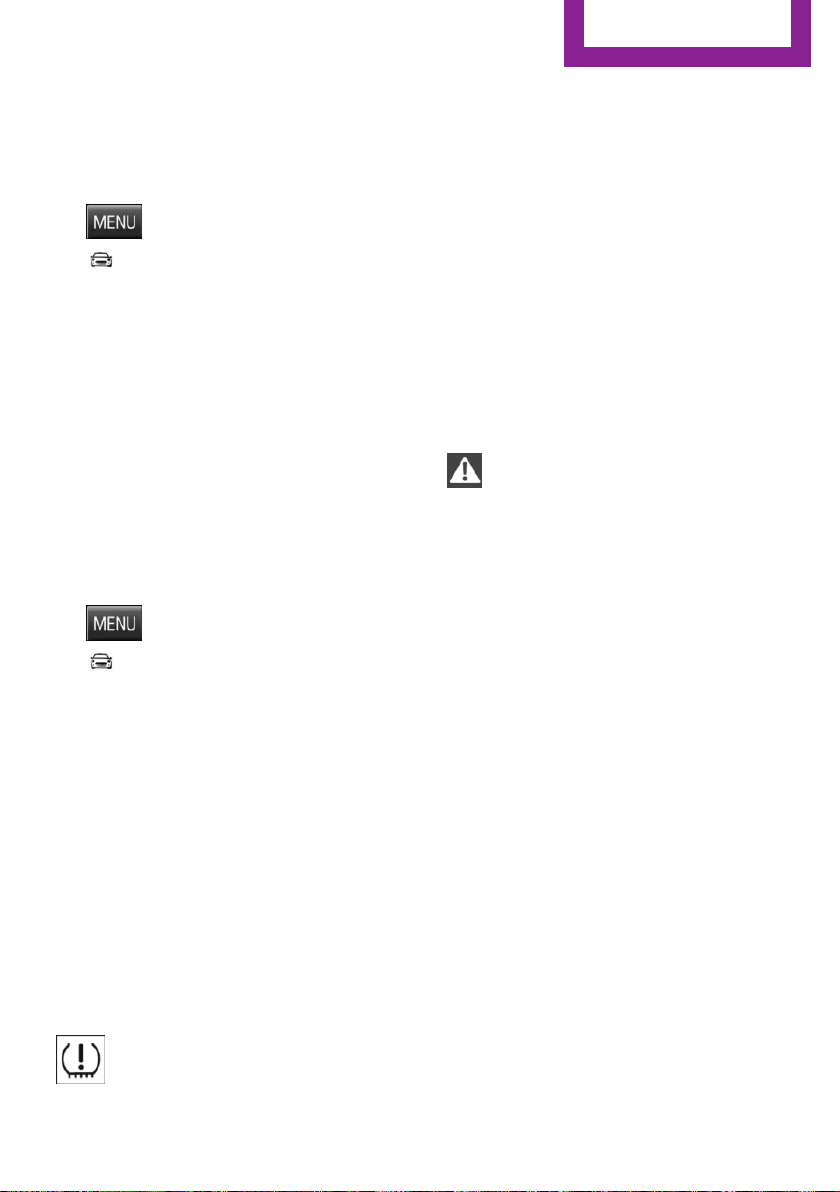
Status display
The current status of the Tire Pressure Monitor
TPM can be displayed, e.g., whether or not the
TPM is active.
1.
Press button.
2. "Vehicle Info"
3. "Vehicle status"
4. "Tire Pressure Monitor (TPM)"
The status is displayed.
In addition, the current tire inflation pressures
are displayed. It shows the actual values read;
they may vary depending on driving style or
weather conditions.
Carry out reset
Reset the system after each adjustment of the
tire inflation pressure and after every tire or
wheel change.
1.
Start the engine - do not drive off.
2.
Press button.
3. "Vehicle Info"
4. "Vehicle status"
5. "Tire Pressure Monitor (TPM)"
6. To reset the tire pressure: "Perform reset"
7. Drive away.
"Resetting…" is displayed.
After driving faster than 19 mph/30 km/h for a
short period, the set tire inflation pressures are
accepted as reference values. The resetting
process is completed automatically while driv‐
ing.
You may interrupt this trip at any time. When
you continue the reset resumes automatically.
Low tire pressure message
The yellow warning lamp lights up. A
Check Control message is displayed.
▷ There is a flat tire or a major loss in tire in‐
flation pressure.
▷ A reset of the system was not carried out
after a wheel was changed. The system
therefore issues a warning based on the tire
pressures before the last reset.
1. Reduce your speed and stop cautiously.
Avoid sudden braking and steering maneu‐
vers.
2. Check whether the vehicle is fitted with
regular tires or run-flat tires.
Run-flat tires, refer to page 187, are la‐
beled with a circular symbol containing the
letters RSC marked on the tire's sidewall.
WARNING
A damaged regular tire with low or miss‐
ing tire inflation pressure impacts handling,
such as steering and braking response. Run-flat
tires can maintain limited stability. There is risk
of an accident. Do not continue driving if the
vehicle is not equipped with run-flat tires. Ob‐
serve the information on run-flat tires and con‐
tinued driving with these tires.◀
A low tire inflation pressure might turn on DSC
Dynamic Stability Control.
Actions in the event of a flat tire
Normal tires
1.
Identify the damaged tire.
Do this by checking the air pressure in all
four tires.
The tire pressure gauge of the Mobility Sys‐
tem, refer to page 188, can be used for this
purpose.
If the tire inflation pressure in all four tires is
correct, the Tire Pressure Monitor may not
have been initialized. In this case, initialize
the system.
If identification of flat tire damage is not
possible, please contact a dealer’s service
Seite 85
Safety
CONTROLS
85
Online Edition for Part no. 01 40 2 963 307 - VI/15

center or another qualified service center or
repair shop.
2. Fix the flat tire using the Mobility System,
refer to page 188.
Use of tire sealant, e.g., the Mobility System,
may damage the TPM wheel electronics. In this
case, have the electronics checked at the next
opportunity and have them replaced if needed.
Run-flat tires
Maximum speed
You may continue driving with a damaged tire
at speeds up to 50 mph/80 km/h.
Continued driving with a flat tire
If continuing to drive with a damaged tire:
1.
Avoid sudden braking and steering maneu‐
vers.
2. Do not exceed a speed of 50 mph/80 km/h.
3. Check the air pressure in all four tires at the
next opportunity.
If the tire inflation pressure in all four tires is
shown to be correct, it is possible that the
Tire Pressure Monitor did not perform a re‐
set. Then perform the reset.
Possible driving distance with complete loss of
tire inflation pressure:
The possible driving distance after a loss of tire
inflation pressure depends on cargo load, driv‐
ing style and road conditions.
A vehicle with an average load has a possible
driving range of approx. 50 miles/80 km.
A vehicle with a damaged tire reacts differently,
e.g., it has reduced lane stability during brak‐
ing, a longer braking distance and different
self-steering properties. Adjust your driving
style accordingly. Avoid abrupt steering ma‐
neuvers or driving over obstacles, e.g., curbs,
potholes, etc.
Because the possible driving distance depends
on how the vehicle is used during the trip, the
actual distance may be shorter or longer de‐
pending on the driving speed, road conditions,
external temperature, cargo load, etc.
WARNING
Your vehicle handles differently when a
run-flat tire is damaged and has low or missing
tire inflation pressure, e.g., your lane stability is
reduced when braking, braking distances are
longer and the self-steering properties will
change. There is risk of an accident.
Drive moderately and do not exceed a speed of
50 mph/80 km/h.◀
Final tire failure
Vibrations or loud noises while driving can indi‐
cate the final failure of a tire.
Reduce speed and stop; otherwise, pieces of
the tire could come loose and cause an acci‐
dent.
Do not continue driving. Contact a dealer’s
service center or another qualified service cen‐
ter or repair shop.
Required inflation pressure check
message
A Check Control message is displayed in the fol‐
lowing situations
▷ The system has detected a wheel change,
but no reset was done.
▷ Inflation was not carried out according to
specifications.
▷ The tire inflation pressure has fallen below
the level of the last confirmation.
In this case:
▷ Check the tire pressure and correct as
needed.
▷ Carry out a reset of the system after a tire
change.
System limits
The system does not function properly if a reset
has not been carried out, e.g., a flat tire is re‐
Seite 86
CONTROLS
Safety
86
Online Edition for Part no. 01 40 2 963 307 - VI/15

ported though tire inflation pressures are cor‐
rect.
The tire inflation pressure depends on the tire's
temperature. Driving or exposure to the sun
will increase the tire's temperature, thus in‐
creasing the tire inflation pressure. The tire in‐
flation pressure is reduced when the tire tem‐
perature falls again. These circumstances may
cause a warning when temperatures fall very
sharply.
The system cannot indicate sudden serious tire
damage caused by external circumstances.
Malfunction
The yellow warning lamp flashes and
then lights up continuously. A Check
Control message is displayed. No flat
tire or loss of tire pressure can be detected.
Examples and recommendations in the follow‐
ing situations:
▷ A wheel without TPM electronics is
mounted, e.g. emergency wheel: Have it
checked by a dealer’s service center or an‐
other qualified service center or repair shop
as needed.
▷ Malfunction: Have system checked by a
dealer’s service center or another qualified
service center or repair shop.
▷ TPM was unable to complete the reset. Re‐
set the system again.
▷ Interference through systems or devices
with the same radio frequency: After leav‐
ing the area of the interference, the system
automatically becomes active again.
Declaration according to NHTSA/FMVSS
138 Tire Pressure Monitoring System
Each tire, including the spare (if provided)
should be checked monthly when cold and in‐
flated to the inflation pressure recommended
by the vehicle manufacturer on the vehicle
placard or tire inflation pressure label. (If your
vehicle has tires of a different size than the size
indicated on the vehicle placard or tire inflation
pressure label, you should determine the
proper tire inflation pressure for those tires.) As
an added safety feature, your vehicle has been
equipped with a tire pressure monitoring sys‐
tem (TPMS) that illuminates a low tire pressure
telltale when one or more of your tires is signifi‐
cantly under-inflated. Accordingly, when the
low tire pressure telltale illuminates, you should
stop and check your tires as soon as possible,
and inflate them to the proper pressure. Driving
on a significantly under-inflated tire causes the
tire to overheat and can lead to tire failure. Un‐
der-inflation also reduces fuel efficiency and
tire tread life, and may affect the vehicle's han‐
dling and stopping ability. Please note that the
TPMS is not a substitute for proper tire mainte‐
nance, and it is the driver's responsibility to
maintain correct tire pressure, even if under-in‐
flation has not reached the level to trigger illu‐
mination of the TPMS low tire pressure telltale.
Your vehicle has also been equipped with a
TPMS malfunction indicator to indicate when
the system is not operating properly. The TPMS
malfunction indicator is combined with the low
tire pressure telltale. When the system detects
a malfunction, the telltale will flash for approxi‐
mately one minute and then remain continu‐
ously illuminated. This sequence will continue
upon subsequent vehicle start-ups as long as
the malfunction exists. When the malfunction
indicator is illuminated, the system may not be
able to detect or signal low tire pressure as in‐
tended. TPMS malfunctions may occur for a va‐
riety of reasons, including the installation of re‐
placement or alternate tires or wheels on the
vehicle that prevent the TPMS from functioning
properly. Always check the TPMS malfunction
telltale after replacing one or more tires or
wheels on your vehicle to ensure that the re‐
placement or alternate tires and wheels allow
the TPMS to continue to function properly.
Seite 87
Safety
CONTROLS
87
Online Edition for Part no. 01 40 2 963 307 - VI/15
FTM Flat Tire Monitor
The concept
The system does not measure the actual infla‐
tion pressure in the tires.
It detects a tire inflation pressure loss by com‐
paring the rotational speeds of the individual
wheels while moving.
In the event of a tire inflation pressure loss, the
diameter and therefore the rotational speed of
the corresponding wheel changes. This will be
detected and reported as a flat tire.
Functional requirements
The system must have been initialized when
the tire inflation pressure was correct; other‐
wise, reliable flagging of a flat tire is not as‐
sured. Initialize the system after each correc‐
tion of the tire inflation pressure and after
every tire or wheel change.
Status display
The current status of the flat tire monitor can
be displayed, e.g., whether the RPA is active.
1. Press button.
2. "Vehicle Info"
3. "Vehicle status"
4. "Flat Tire Monitor (FTM)"
The status is displayed.
Initialization
When initializing the once set inflation tire pres‐
sures serve as reference values in order to de‐
tect a flat tire. Initialization is started by con‐
firming the inflation pressures.
Do not initialize the system when driving with
snow chains.
1. Press button.
2. "Vehicle Info"
3. "Vehicle status"
4. "Flat Tire Monitor (FTM)"
5. Start the engine - do not drive off.
6. Start the initialization with "Flat Tire
Monitor (FTM) reset".
7. Drive away.
The initialization is completed while driving,
which can be interrupted at any time.
The initialization automatically continues when
driving resumes.
Indication of a flat tire
The yellow warning lamp lights up. A
Check Control message is displayed.
There is a flat tire or a major loss in tire
inflation pressure.
1.
Reduce your speed and stop cautiously.
Avoid sudden braking and steering maneu‐
vers.
2. Check whether the vehicle is fitted with
normal tires or run-flat tires.
Run-flat tires, refer to page 187, are la‐
beled with a circular symbol containing the
letters RSC marked on the tire's sidewall.
WARNING
A damaged regular tire with low or miss‐
ing tire inflation pressure impacts handling,
such as steering and braking response. Run-flat
tires can maintain limited stability. There is risk
of an accident. Do not continue driving if the
vehicle is not equipped with run-flat tires. Ob‐
serve the information on run-flat tires and con‐
tinued driving with these tires.◀
When a flat tire is indicated, DSC Dynamic Sta‐
bility Control is switched on if needed.
System limits
A natural, even tire inflation pressure loss in all
four tires will not be recognized. Therefore,
check the tire inflation pressure regularly.
Seite 88
CONTROLS
Safety
88
Online Edition for Part no. 01 40 2 963 307 - VI/15

Sudden serious tire damage caused by external
circumstances cannot be recognized in ad‐
vance.
The system could be delayed or malfunction in
the following situations:
▷ When the system has not been initialized.
▷ When driving on a snowy or slippery road
surface.
▷ Sporty driving style: spinning traction
wheels, high lateral acceleration (drifting).
▷ When driving with snow chains.
Actions in the event of a flat tire
Normal tires
1.
Identify the damaged tire.
Do this by checking the air pressure in all
four tires.
The tire pressure gauge of the Mobility Sys‐
tem, refer to page 188, can be used for this
purpose.
If the tire inflation pressure in all four tires is
correct, the Flat Tire Monitor may not have
been initialized. In this case, initialize the
system.
If identification of flat tire damage is not
possible, please contact a dealer’s service
center or another qualified service center or
repair shop.
2.
Fix the flat tire using the Mobility System,
refer to page 188.
Run-flat tires
Maximum speed
You may continue driving with a damaged tire
at speeds up to 50 mph/80 km/h.
Continued driving with a flat tire
If continuing to drive with a damaged tire:
1.
Avoid sudden braking and steering maneu‐
vers.
2. Do not exceed a speed of 50 mph/80 km/h.
3. Check the air pressure in all four tires at the
next opportunity.
If the tire inflation pressure in all four tires is
correct, the Flat Tire Monitor may not have
been initialized. In this case, initialize the
system.
Possible driving distance with complete loss of
tire inflation pressure:
The possible driving distance after a loss of tire
inflation pressure depends on cargo load, driv‐
ing style and road conditions.
A vehicle with an average load has a possible
driving range of approx. 50 miles/80 km.
A vehicle with a damaged tire reacts differently,
e.g., it has reduced lane stability during brak‐
ing, a longer braking distance and different
self-steering properties. Adjust your driving
style accordingly. Avoid abrupt steering ma‐
neuvers or driving over obstacles, e.g., curbs,
potholes, etc.
Because the possible driving distance depends
on how the vehicle is used during the trip, the
actual distance may be shorter or longer de‐
pending on the driving speed, road conditions,
external temperature, cargo load, etc.
WARNING
Your vehicle handles differently when a
run-flat tire is damaged and has low or missing
tire inflation pressure, e.g., your lane stability is
reduced when braking, braking distances are
longer and the self-steering properties will
change. There is risk of an accident.
Drive moderately and do not exceed a speed of
50 mph/80 km/h.◀
Final tire failure
Vibrations or loud noises while driving can indi‐
cate the final failure of a tire.
Reduce speed and stop; otherwise, pieces of
the tire could come loose and cause an acci‐
dent.
Seite 89
Safety
CONTROLS
89
Online Edition for Part no. 01 40 2 963 307 - VI/15
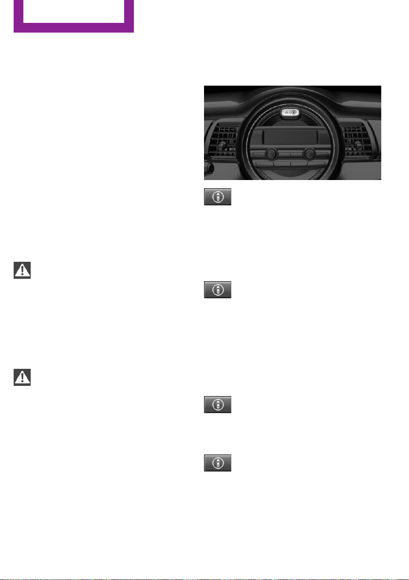
Do not continue driving. Contact a dealer’s
service center or another qualified service cen‐
ter or repair shop.
Intelligent Safety
The concept
Intelligent Safety enables central operation of
the driver assistance system.
The intelligent safety systems can hel prevent
an imminent collision.
▷ Front-end collision warning with City Brak‐
ing function, refer to page 91.
▷ Pedestrian warning with City Braking func‐
tion, refer to page 94.
Information
WARNING
Indicators and warnings do not relieve
from the personal responsibility. Due to system
limits, warnings or reactions of the system may
not be output or they may be output too late or
incorrectly. There is risk of an accident. Adjust
the driving style to the traffic conditions. Watch
traffic closely and actively interfere in the re‐
spective situations.◀
WARNING
Due to system limits, individual functions
can malfunction during tow-starting/towing
with the Intelligent Safety systems activated,
e.g. approach control warning with light brak‐
ing function. There is risk of an accident. Switch
all Intelligent Safety systems off prior to tow-
starting/towing.◀
Overview
Button in the vehicle
Intelligent Safety button
Switching on/off
Some Intelligent Safety systems are automati‐
cally active after every departure. Some Intelli‐
gent Safety systems activate according to the
last setting.
Press button briefly:
▷ The menu for the intelligent safety
system is displayed. The systems
are individually switched off ac‐
cording to their respective settings.
▷ LED lights up orange or goes out respective
to their individual settings.
Adjust as needed. Individual settings are stored
for the profile currently used.
Press button again:
▷ All Intelligent Safety systems are
activated.
▷ The LED lights up green.
Hold down button:
▷ All Intelligent Safety systems are
turned off.
▷ The LED goes out.
Seite 90
CONTROLS
Safety
90
Online Edition for Part no. 01 40 2 963 307 - VI/15
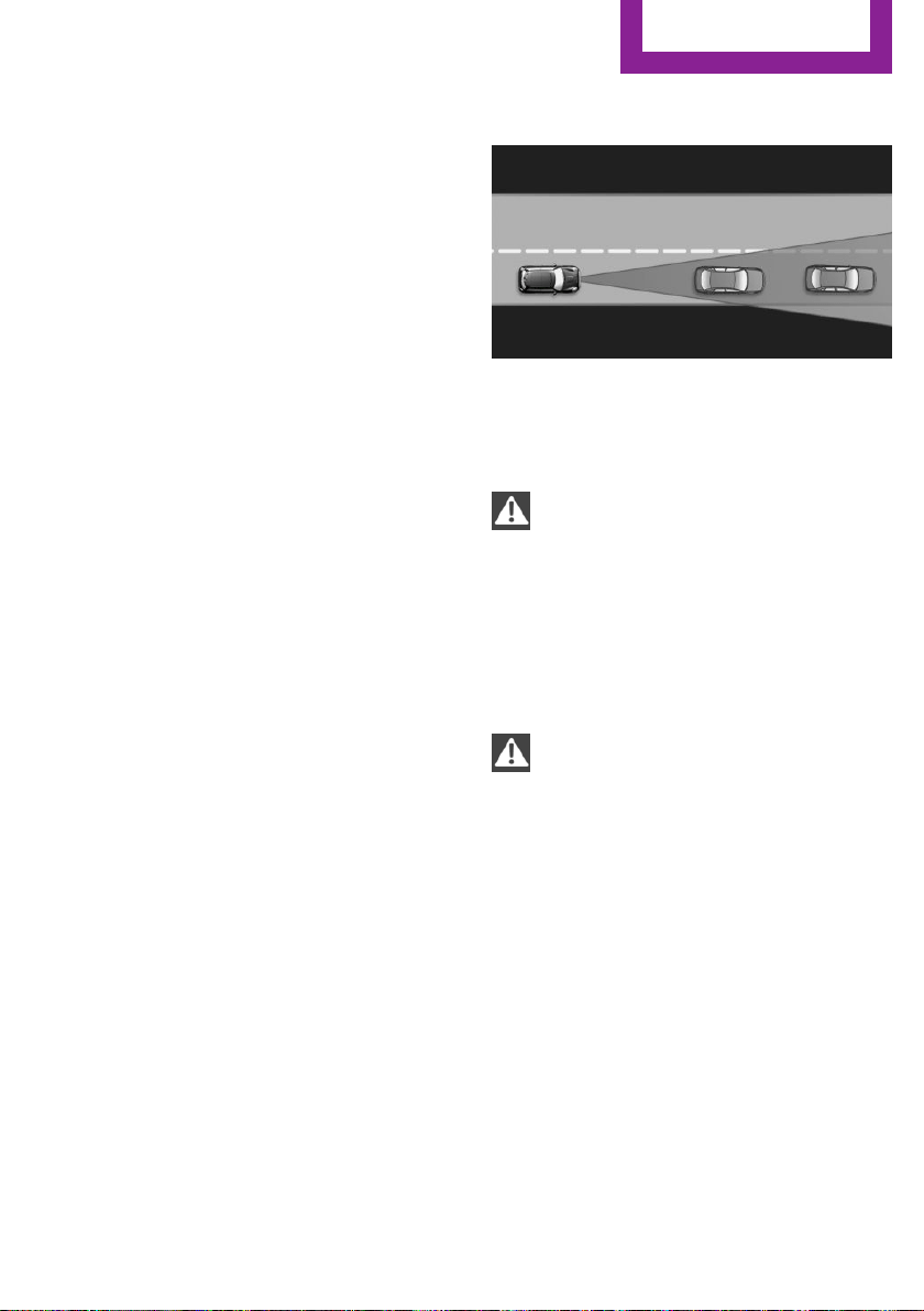
Front-end collision
warning with City Brak‐
ing function
The concept
The system can help prevent accidents. If an
accident cannot be prevented, the system will
help reduce the collision speed.
The system sounds a warning before an immi‐
nent collision and actuates brakes independ‐
ently if needed.
The automatic braking intervention is done
with limited force and duration.
The system is controlled via a camera in the
base of the mirror.
The front-end collision warning is available
even if cruise control has been deactivated.
With the vehicle approaching another vehicle
intentionally, the collision warning and braking
are delayed in order to avoid false system reac‐
tions.
General information
The system warns at two levels of an imminent
danger of collision at speeds from approx.
3 mph/5 km/h. Time of warnings may vary with
the current driving situation.
Appropriate braking kicks in at speeds of up to
35 mph/60 km/h.
Detection range
It responds to objects if they are detected by
the system.
Information
WARNING
Indicators and warnings do not relieve
from the personal responsibility. Due to system
limits, warnings or reactions of the system may
not be output or they may be output too late or
incorrectly. There is risk of an accident. Adjust
the driving style to the traffic conditions. Watch
traffic closely and actively interfere in the re‐
spective situations.◀
WARNING
Due to system limits, individual functions
can malfunction during tow-starting/towing
with the Intelligent Safety systems activated,
e.g. approach control warning with light brak‐
ing function. There is risk of an accident. Switch
all Intelligent Safety systems off prior to tow-
starting/towing.◀
Seite 91
Safety
CONTROLS
91
Online Edition for Part no. 01 40 2 963 307 - VI/15
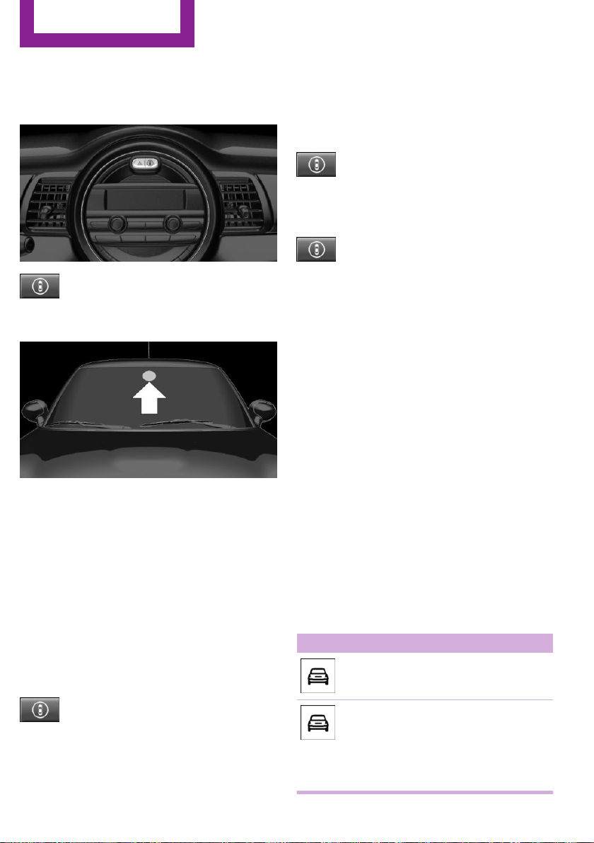
Overview
Button in the vehicle
Intelligent Safety button
Camera
The camera is installed near the interior rear‐
view mirror.
Keep the windshield in the area behind the in‐
terior rearview mirror clean and clear.
Switching on/off
Switching on automatically
The system is automatically active after every
driving-off.
Switching on/off manually
Press button briefly:
▷ The menu for the intelligent safety
system is displayed. The systems
are individually switched off ac‐
cording to their respective settings.
▷ LED lights up orange or goes out respective
to their individual settings.
Adjust as needed. Individual settings are stored
for the profile currently used.
Press button again:
▷ All Intelligent Safety systems are
activated.
▷ The LED lights up green.
Hold down button:
▷ All Intelligent Safety systems are
turned off.
▷ The LED goes out.
Setting the warning time
The warning time can be set on the radio.
1.
Intelligent Safety button
The intelligent safety menu is displayed for
a brief time on the radio display.
2. "Front. Coll. Warn."
3. "Warning time"
4. Setting the desired warning time
The selected warning time is stored for the pro‐
file currently used.
Warning with braking function
Display
If a collision with a vehicle detected in this way
is imminent, a warning symbol appears on the
instrument cluster.
Symbol Measure
Symbol lights up red: prewarning.
Brake and increase distance.
Symbol flashes red and an acoustic
signal sounds: acute warning.
You are requested to intervene by
braking or make an evasive maneu‐
ver.
Seite 92
CONTROLS
Safety
92
Online Edition for Part no. 01 40 2 963 307 - VI/15

Prewarning
This warning is issued, e.g., when there is the
impending danger of a collision or the distance
to the vehicle ahead is too small.
The driver must intervene actively when there
is a prewarning.
Acute warning with braking function
Acute warning in displayed in case of the immi‐
nent danger of a collision when the vehicle ap‐
proaches another object at a relatively high dif‐
ferential speed.
The driver must intervene actively when there
is an acute warning. If necessary, the driver is
assisted by a minor automatic braking inter‐
vention in a possible risk of collision.
Acute warnings can also be triggered without
previous forewarning.
Braking intervention
The warning prompts the driver himself/herself
to react. During a warning, the maximum brak‐
ing force is used. Premise for the brake booster
is sufficiently quick and sufficiently hard step‐
ping on the brake pedal. The system can assist
with some braking intervention if there is risk of
a collision. At low speeds vehicles may thus
come to a complete stop.
Manual transmission: During a braking inter‐
vention up to a complete stop, the engine may
be shut down.
The braking intervention is executed only if DSC
Dynamic Stability Control is switched on.
The braking intervention can be interrupted by
stepping on the accelerator pedal or by actively
moving the steering wheel.
Object detection can be restricted. Limitations
of the detection range and functional restric‐
tions are to be considered.
System limits
Detection range
The system's detection potential is limited.
Thus a system reaction might not come or
might come late.
E. g. the following situations may not be de‐
tected:
▷ Slow moving vehicles when you approach
them at high speed.
▷ Vehicles that suddenly swerve in front of
you, or sharply decelerating vehicles.
▷ Vehicles with an unusual rear appearance.
▷ Two-wheeled vehicles ahead of you.
Functional limitations
The system may not be fully functional in the
following situations:
▷ In heavy fog, rain, sprayed water or snow‐
fall.
▷ In tight curves.
▷ If the field of view of the camera or the
front windshield are dirty or covered.
▷ If the driving stability control systems are
deactivated, e.g. DSC OFF.
▷ Up to 10 seconds after the start of the en‐
gine, via the Start/Stop button.
▷ During calibration of the camera immedi‐
ately after vehicle delivery.
▷ If there are constant blinding effects be‐
cause of oncoming light, e. g., from the sun
low in the sky.
Warning sensitivity
The more sensitive the warning settings are,
the more warnings are displayed. However,
there may also be an excess of false warnings.
Seite 93
Safety
CONTROLS
93
Online Edition for Part no. 01 40 2 963 307 - VI/15
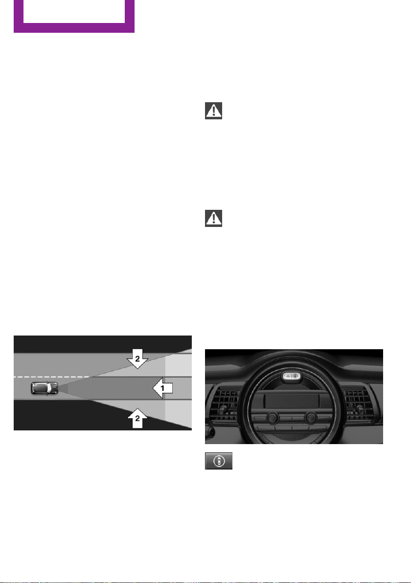
Pedestrian warning with
city braking function
The concept
The system can help prevent accidents with pe‐
destrians.
The system issues a warning in the city driving
speed area if there is imminent danger of a col‐
lision with pedestrians and includes a braking
function.
A camera at the base of the rearview mirror
controls the system.
General information
With sufficient brightness, the system warns
about possible collision danger with pedes‐
trians starting at approx. 6 mph/10 km/h to ap‐
prox. 35 mph/60 km/h and assists with braking
before a collision.
Under those circumstances it reacts to people
who are within the detection range of the sys‐
tem.
Detection range
The detection area in front of the vehicle is div‐
ided into two areas
▷ Central area, arrow 1, directly in front of the
vehicle.
▷ Expanded area, arrow 2, to the right and
left.
A collision is imminent if pedestrians are lo‐
cated within the central area. A warning is is‐
sued about pedestrians who are located within
the extended area only if they are moving in
the direction of the central area.
Information
WARNING
Indicators and warnings do not relieve
from the personal responsibility. Due to system
limits, warnings or reactions of the system may
not be output or they may be output too late or
incorrectly. There is risk of an accident. Adjust
the driving style to the traffic conditions. Watch
traffic closely and actively interfere in the re‐
spective situations.◀
WARNING
Due to system limits, individual functions
can malfunction during tow-starting/towing
with the Intelligent Safety systems activated,
e.g. approach control warning with light brak‐
ing function. There is risk of an accident. Switch
all Intelligent Safety systems off prior to tow-
starting/towing.◀
Overview
Button in the vehicle
Intelligent Safety button
Seite 94
CONTROLS
Safety
94
Online Edition for Part no. 01 40 2 963 307 - VI/15
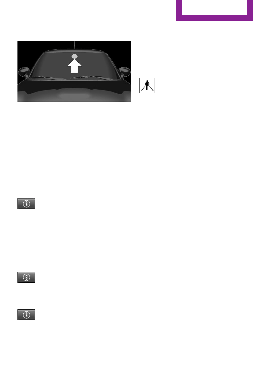
Camera
The camera is installed near the interior rear‐
view mirror.
Keep the windshield in the area behind the in‐
terior rearview mirror clean and clear.
Switching on/off
Switching on automatically
The system is automatically active after every
driving-off.
Switching on/off manually
Press button briefly:
▷ The menu for the intelligent safety
system is displayed. The systems
are individually switched off ac‐
cording to their respective settings.
▷ LED lights up orange or goes out respective
to their individual settings.
Adjust as needed. Individual settings are stored
for the profile currently used.
Press button again:
▷ All Intelligent Safety systems are
activated.
▷ The LED lights up green.
Hold down button:
▷ All Intelligent Safety systems are
turned off.
▷ The LED goes out.
Warning with braking function
Display
If a collision with a person detected in this way
is imminent, a warning symbol appears on the
instrument cluster.
The red symbol is displayed and a signal
sounds.
Intervene immediately by braking or
make an evasive maneuver.
Braking intervention
The warning prompts the driver himself/herself
to react. During a warning, the maximum brak‐
ing force is used. Premise for the brake booster
is sufficiently quick and sufficiently hard step‐
ping on the brake pedal. The system can assist
with some braking intervention if there is risk of
a collision. At low speeds vehicles may thus
come to a complete stop.
Manual transmission: During a braking inter‐
vention up to a complete stop, the engine may
be shut down.
The braking intervention is executed only if DSC
Dynamic Stability Control is switched on.
The braking intervention can be interrupted by
stepping on the accelerator pedal or by actively
moving the steering wheel.
Object detection can be restricted. Limitations
of the detection range and functional restric‐
tions are to be considered.
System limits
Detection range
The detection potential of the camera is lim‐
ited.
Thus a warning might not be issued or be is‐
sued late.
E. g. the following situations may not be de‐
tected:
▷ Partially covered pedestrians.
Seite 95
Safety
CONTROLS
95
Online Edition for Part no. 01 40 2 963 307 - VI/15

▷ Pedestrians that are not detected as such
because of the viewing angle or contour.
▷ Pedestrians outside of the detection range.
▷ Pedestrians having a body size less than
32 in/80 cm.
Functional limitations
The system may not be fully functional or may
not be available in the following situations:
▷ In heavy fog, rain, sprayed water or snow‐
fall.
▷ In tight curves.
▷ If the field of view of the camera or the
front windshield are dirty or covered.
▷ If the driving stability control systems are
deactivated, e.g. DSC OFF.
▷ Up to 10 seconds after the start of the en‐
gine, via the Start/Stop button.
▷ During calibration of the camera immedi‐
ately after vehicle delivery.
▷ If there are constant blinding effects be‐
cause of oncoming light, e. g., from the sun
low in the sky.
▷ When it is dark outside.
Brake force display
The concept
▷ During normal brake application, the brake
lights light up.
▷ During heavy brake application, the flash‐
ers light up in addition.
PostCrash
In the event of an accident, the system can
bring the car to a halt automatically without in‐
tervention by the driver in certain situations.
This can reduce the risk of a further collision
and the consequences thereof.
Depressing the brake pedal can cause the vehi‐
cle to brake harder. This interrupts automatic
braking. Destepping on the gas pedal also in‐
terrupts automatic braking.
After coming to a halt, the brake is released au‐
tomatically. Secure the vehicle against rolling.
Seite 96
CONTROLS
Safety
96
Online Edition for Part no. 01 40 2 963 307 - VI/15

Driving stability control systems
Vehicle features and op‐
tions
This chapter describes all standard, country-
specific and optional features offered with the
series. It also describes features that are not
necessarily available in your car, e. g., due to
the selected options or country versions. This
also applies to safety-related functions and sys‐
tems. The respectively applicable country provi‐
sions must be observed when using the respec‐
tive features and systems.
Anti-lock Braking System
ABS
ABS prevents locking of the wheels during
braking.
The vehicle contains its steering power even
during full brake applications, thus increasing
active safety.
ABS is operational every time you start the en‐
gine.
Brake assistant
When you apply the brakes rapidly, this system
automatically produces the greatest possible
braking force boost. It reduces the braking dis‐
tance to a minimum during emergency stop.
This system utilizes all of the benefits provided
by ABS.
Do not reduce the pressure on the brake pedal
for the duration of the emergency stop.
DSC Dynamic Stability
Control
The concept
DSC prevents traction loss in the power wheels
when driving off and accelerating.
DSC also recognizes unstable vehicle conditions
such as fishtailing or nose-diving. Within the
physical limits DSC helps to keep the vehicle on
a steady course by reducing engine speed and
by applying brakes to the individual wheels.
Information
Adapt your driving style to the situation, for an
appropriate driving style is always the responsi‐
bility of the driver.
The laws of physics cannot be repealed, not
even with DSC.
Therefore, do not reduce the additional safety
margin by driving in a risky manner.
WARNING
When driving with roof load, e.g. with
roof-mounted luggage rack, driving safety may
not be ensured in driving-critical situations due
to the elevated center of gravity. There is risk of
accidents or risk of property damage. Do not
deactivate Dynamic Stability Control DSC when
driving with roof load.◀
Indicator/warning lights
The indicator lamp flashes: DSC controls
the drive and braking forces.
The indicator lamp lights up: DSC has
failed.
Seite 97
Driving stability control systems
CONTROLS
97
Online Edition for Part no. 01 40 2 963 307 - VI/15
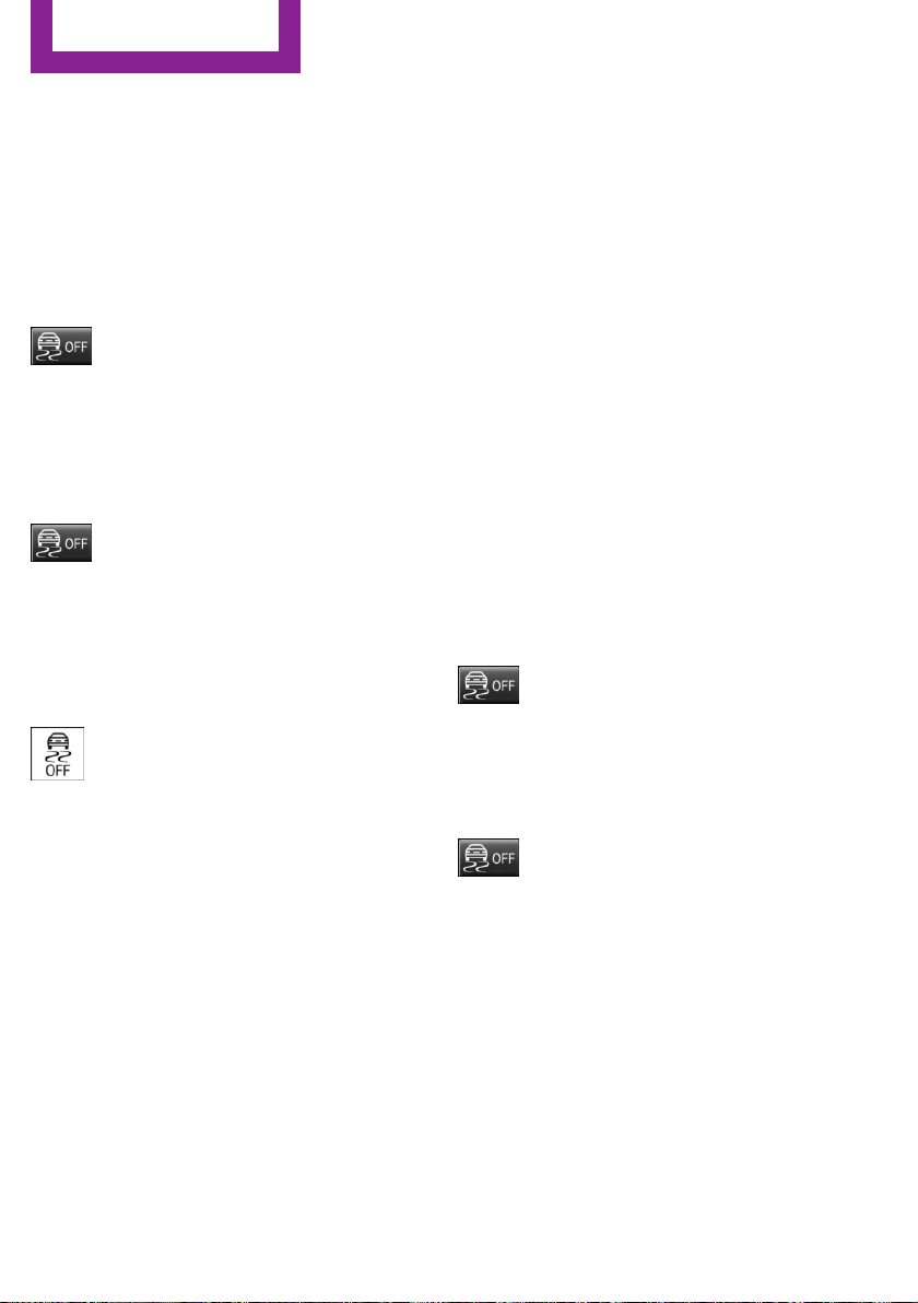
Deactivating DSC: DSC OFF
When DSC is deactivated, driving stability is re‐
duced during acceleration and when driving in
curves.
To increase vehicle stability, activate DSC again
as soon as possible.
Deactivating DSC
Press and hold this button but not lon‐
ger than approx. 10 seconds, until the
indicator lamp for DSC OFF lights up in the in‐
strument cluster and displays DSC OFF.
The DSC system is switched off.
Activating DSC
Press button.
DSC OFF and the DSC OFF indicator
lamp go out.
Indicator/warning lights
When DSC is deactivated, DSC OFF is displayed
in the instrument cluster.
The indicator lamp lights up: DSC is de‐
activated.
Automatic activation
When DSC is deactivated, automatic activation
occurs in the following situations:
▷ The vehicle has a flat tire.
▷ When activating cruise control in TRACTION
or DSC OFF mode.
DTC Dynamic Traction
Control
The concept
The DTC system is a version of the DSC where
forward momentum is optimized.
The system ensures maximum headway on
special road conditions or loose road surfaces,
e.g., unplowed snowy roads, but with some‐
what limited driving stability.
Activating the Dynamic Traction Control DTC
provides maximum traction. Driving stability is
limited during acceleration and when driving in
curves.
Therefore drive with appropriate caution.
You may find it useful to briefly activate DTC
under the following special circumstances:
▷ When driving in slush or on uncleared,
snow-covered roads.
▷ When freeing vehicle from deep snow or
driving off from loose grounds.
▷ When driving with snow chains.
Deactivating/activating DTC Dynamic
Traction Control
Activating DTC
Press button.
TRACTION is displayed in the instru‐
ment cluster and the indicator lamp for DSC
OFF lights up.
Deactivating DTC
Press button again.
TRACTION and the DSC OFF indicator
lamp go out.
Performance Control
Performance Control enhances the agility of the
vehicle.
To increase maneuverability, with a corre‐
spondingly sporty driving style, wheels are
braked individually.
Seite 98
CONTROLS
Driving stability control systems
98
Online Edition for Part no. 01 40 2 963 307 - VI/15
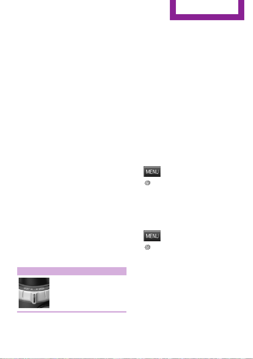
Dynamic Damping Con‐
trol
The concept
The tuning of the suspension can be changed
with the system.
Programs
The system offers several different programs.
Select the programs via the Driving Dynamics
Control, refer to page 99.
MID/GREEN
Balanced tuning of the shock absorbers for
more comfort.
SPORT
Consistently sporty tuning of the shock absorb‐
ers for greater driving agility.
Driving Dynamics Con‐
trol
The concept
The Driving Dynamics Control helps to fine-
tune the vehicle's settings and features. Choose
between three different programs. Driving Dy‐
namics Control will activate the particular pro‐
gram.
Operating the programs
Driving Dynamics Control Program
MID
GREEN
SPORT
MID
For balanced tuning.
With each starting operation, MID is activated
using the Start/Stop button.
GREEN
GREEN, refer to page 143, provides consistent
tuning to maximize range.
Activating GREEN
Turn Driving Dynamics Control to the right until
GREEN is displayed in the instrument cluster.
Configuring GREEN
Via the Driving Dynamics Control
1.
Activate GREEN.
2. "Configure GREEN"
3. Configure the program.
Via radio
1. Press button.
2. "Settings"
3. "Driving mode"
4. "Configure GREEN"
5. Configure the program.
For vehicles without a configurable SPORT pro‐
gram:
1. Press button.
2. "Settings"
3. "GREEN Mode"
4. Configure the program.
This configuration is retrieved when GREEN is
activated.
SPORT
Consistently sporty tuning of the engine control
for greater driving agility.
With the appropriate equipment, the tuning of
the suspension also changes and SPORT can be
individually configured.
Seite 99
Driving stability control systems
CONTROLS
99
Online Edition for Part no. 01 40 2 963 307 - VI/15
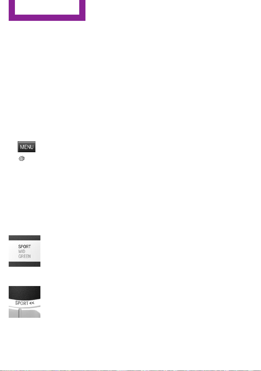
The configuration is stored for the profile cur‐
rently used.
Activating SPORT
Turn Driving Dynamics Control to the left until
SPORT is displayed in the instrument cluster.
Configuring SPORT
Depending on your vehicle's optional features,
SPORT can be individually configured.
Activating SPORT.
Select "Driving mode".
Configure the program.
Set via radio.
1. Press button.
2. "Settings"
3. "Driving mode"
4. "Configure SPORT"
5. Make the desired settings.
This configuration is retrieved when SPORT is
activated.
Displays
Program selection
With Driving Dynamics Control
turned on a list of programs is
displayed and can be selected.
Selected program
The instrument cluster displays
the selected program.
Drive-off assistant
This system supports driving off on inclines. The
parking brake is not required.
1. Hold the vehicle in place with the foot
brake.
2. Release the foot brake and drive off with‐
out delay.
After the foot brake is released, the vehicle is
held in place for approx. 2 seconds.
For vehicles with respective equipment ver‐
sions, the possible holding duration amounts to
2 minutes.
Seite 100
CONTROLS
Driving stability control systems
100
Online Edition for Part no. 01 40 2 963 307 - VI/15

Driving comfort
Vehicle features and op‐
tions
This chapter describes all standard, country-
specific and optional features offered with the
series. It also describes features that are not
necessarily available in your car, e. g., due to
the selected options or country versions. This
also applies to safety-related functions and sys‐
tems. The respectively applicable country provi‐
sions must be observed when using the respec‐
tive features and systems.
Camera-based cruise con‐
trol
The concept
Use this system to select a desired speed that
the vehicle will maintain automatically on clear
roads.
To the extent possible, the system automati‐
cally adjusts the speed to a slower vehicle
ahead of you.
A camera on the interior rear view mirror is
used to detect vehicles driving ahead.
The distance that the vehicle maintains to the
vehicle ahead of you can be varied.
For safety reasons, it depends on the speed.
To maintain a certain distance, the system au‐
tomatically decelerates, applies the brakes
lightly, or accelerates again if the vehicle ahead
begins moving faster.
As soon as the road is clear, the vehicle acceler‐
ates to the desired speed.
The speed is also maintained downhill, but may
not be maintained uphill if engine power is in‐
sufficient.
General information
The system is functional at speeds beginning at
approx. 20 mph/30 km/h.
Active cruise control is paused below approx.
20 mph/30 km/h.
The system does not brake to a stop.
Depending on the driving program, refer to
page 99, set, the characteristics of the cruise
control in particular areas can change.
Information
WARNING
The system does not relieve from the per‐
sonal responsibility to correctly assess the traf‐
fic situation. Based on the limits of the system,
it cannot independently react to all traffic situa‐
tions. There is risk of an accident. Adjust the
driving style to the traffic conditions. Watch
traffic closely and actively interfere in the re‐
spective situations.◀
WARNING
The system does not relieve from the per‐
sonal responsibility to correctly assess visibility
and traffic situation. There is risk of an accident.
Adjust the driving style to the traffic conditions.
Watch traffic closely and actively interfere in
the respective situations.◀
Overview
Buttons on the steering wheel
Press button Function
Cruise control on/off, refer to
page 102
Store/maintain speed, refer to
page 103
Seite 101
Driving comfort
CONTROLS
101
Online Edition for Part no. 01 40 2 963 307 - VI/15
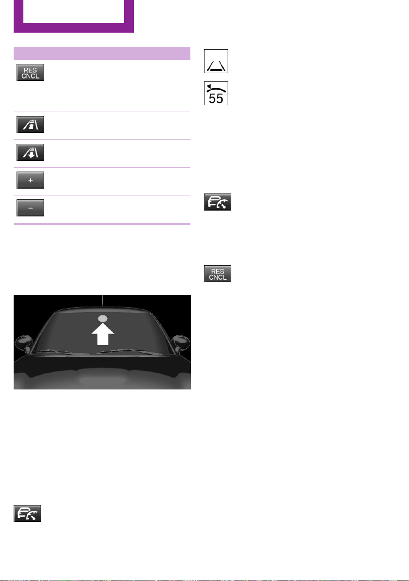
Press button Function
Pause cruise control, refer to
page 102
Continue cruise control with the
last setting, refer to page 103
Reduce distance, refer to
page 103
Increase distance, refer to
page 103
Increase, maintain, and store
speed, refer to page 103
Reduce, maintain, and store
speed, refer to page 103
Buttons are arranged according to vehicle's ser‐
ies, optional features and country specifica‐
tions.
Camera
The camera is installed near the interior rear‐
view mirror.
Keep the windshield in the area behind the in‐
terior rearview mirror clean and clear.
Switching on/off and interrupting cruise
control
Switching on
Press button on the steering wheel.
Display in the instrument cluster lights
up.
Display in the instrument cluster lights
up. The current speed is adopted as de‐
sired speed and displayed with symbol.
Cruise control is active and maintains the set
speed.
DSC Dynamic Stability Control will be switched
on if needed.
Switch off
Press button on the steering wheel.
The displays go out. The stored desired speed is
deleted.
Interrupting
Press button on the steering wheel.
The system is automatically interrupted in the
following situations:
▷ When the brakes are applied.
▷ If the clutch pedal is depressed for a few
seconds or released while a gear is not en‐
gaged.
▷ If selector lever position N is set.
▷ When DTC Dynamic Traction Control is acti‐
vated or DSC is deactivated.
▷ When DSC is actively controlling stability.
▷ If the detection range of the camera is im‐
paired, e.g., by soiling, heavy precipitation
or glare effects from the sun.
▷ If the vehicle in front decelerates below a
speed of approx. 20 mph/30 km/h.
Seite 102
CONTROLS
Driving comfort
102
Online Edition for Part no. 01 40 2 963 307 - VI/15
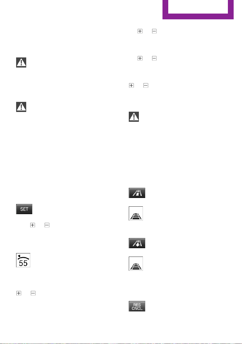
Maintaining, storing, and changing the
speed
Information
WARNING
The desired speed can be incorrectly ad‐
justed or called up by mistake. There is risk of
an accident. Adjust the desired speed to the
traffic conditions. Watch traffic closely and ac‐
tively interfere in the respective situations.◀
WARNING
Risk of accident due to too high speed
differences to other vehicles, e.g. in the follow‐
ing situations:
▷ When fast approaching a slowly moving ve‐
hicle.
▷ Suddenly swerving vehicle onto the own
lane.
▷ When fast approaching standing vehicles.
There is risk of injuries or danger to life. Watch
traffic closely and actively interfere in the re‐
spective situations.◀
Maintaining/storing the speed
Press button.
Or:
Press or button in the interrupted state.
When the system is switched on, the current
speed is maintained and stored as the desired
speed.
The speed is displayed on the symbol.
DSC Dynamic Stability Control will be
switched on if needed.
Changing the speed
or button: press until the desired speed
is set.
If active, the displayed speed is stored and the
vehicle reaches the stored speed when the
road is clear.
▷ or button: each time it is pressed to
the point of resistance, the desired speed
increases or decreases by approx.
1 mph/1 km/h.
▷ or button: each time it is pressed
past the point of resistance, the desired
speed increases or decreases by a maxi‐
mum of 5 mph/10 km/h.
or button: hold down to repeat the cor‐
responding action.
Distance
WARNING
The system does not relieve from the per‐
sonal responsibility. Due to the system limits,
braking can be late. There is risk of accidents or
risk of property damage. Be aware to the traffic
situation at all times. Adjust the distance to the
traffic and weather conditions and maintain the
prescribed safety distance, possibly by brak‐
ing.◀
Reduce distance
Press button repeatedly until the de‐
sired distance is set.
The set distance is briefly displayed in
the left part of the instrument cluster.
Increase distance
Press button repeatedly until the de‐
sired distance is set.
The set distance is briefly displayed in
the left part of the instrument cluster.
Continue cruise control
While driving
Press button with the system inter‐
rupted. Cruise control is continued with
Seite 103
Driving comfort
CONTROLS
103
Online Edition for Part no. 01 40 2 963 307 - VI/15
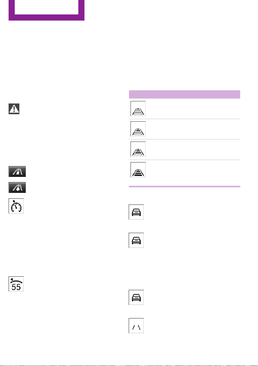
the saved values. The selected distance is
briefly displayed in the info display.
In the following cases, the stored speed value is
deleted and cannot be called up again:
▷ When the system is switched off.
▷ When the ignition is switched off.
Changing between cruise control with/
without distance control
WARNING
The system does not react to traffic driv‐
ing ahead of you, but instead maintains the
stored speed. There is risk of accidents or risk of
property damage. Adjust the desired speed to
the traffic conditions and brake as needed.◀
Changing to Active Cruise Control without dis‐
tance control:
Press and hold this button, or
Press and hold this button.
The indicator lamp in the instrument
cluster lights up.
To switch back to cruise control, press one of
the buttons briefly.
After switching, a Check Control message is dis‐
played.
Displays in the instrument cluster
Desired speed
In addition to the indicator lamp, the
desired speed is displayed in the central
information display.
▷ The indicator lights up green: the system is
active.
▷ The indicator lights up orange: the system
has been interrupted.
▷ No display: system is switched off.
If no speed is indicated, it is possible that the
conditions necessary for operation are not cur‐
rently fulfilled.
Distance to vehicle ahead of you
Selected distance from the vehicle driving
ahead is briefly displayed in the left hand por‐
tion of the info display.
Distance display
Distance 1
Distance 2
Distance 3
Distance 4
This value is set automatically after
the system is switched on.
Indicator/warning lights
Symbol lights up orange:
A vehicle has been detected ahead of
you.
Symbol flashes orange:
The conditions are not adequate for the
system to work.
The system was deactivated but applies the
brakes until you actively resume control by
pressing on the brake pedal or accelerator
pedal.
Symbol flashes red and a signal sounds:
You are requested to intervene by brak‐
ing or make an evasive maneuver.
The system has been interrupted or dis‐
tance control is temporarily suppressed
Seite 104
CONTROLS
Driving comfort
104
Online Edition for Part no. 01 40 2 963 307 - VI/15
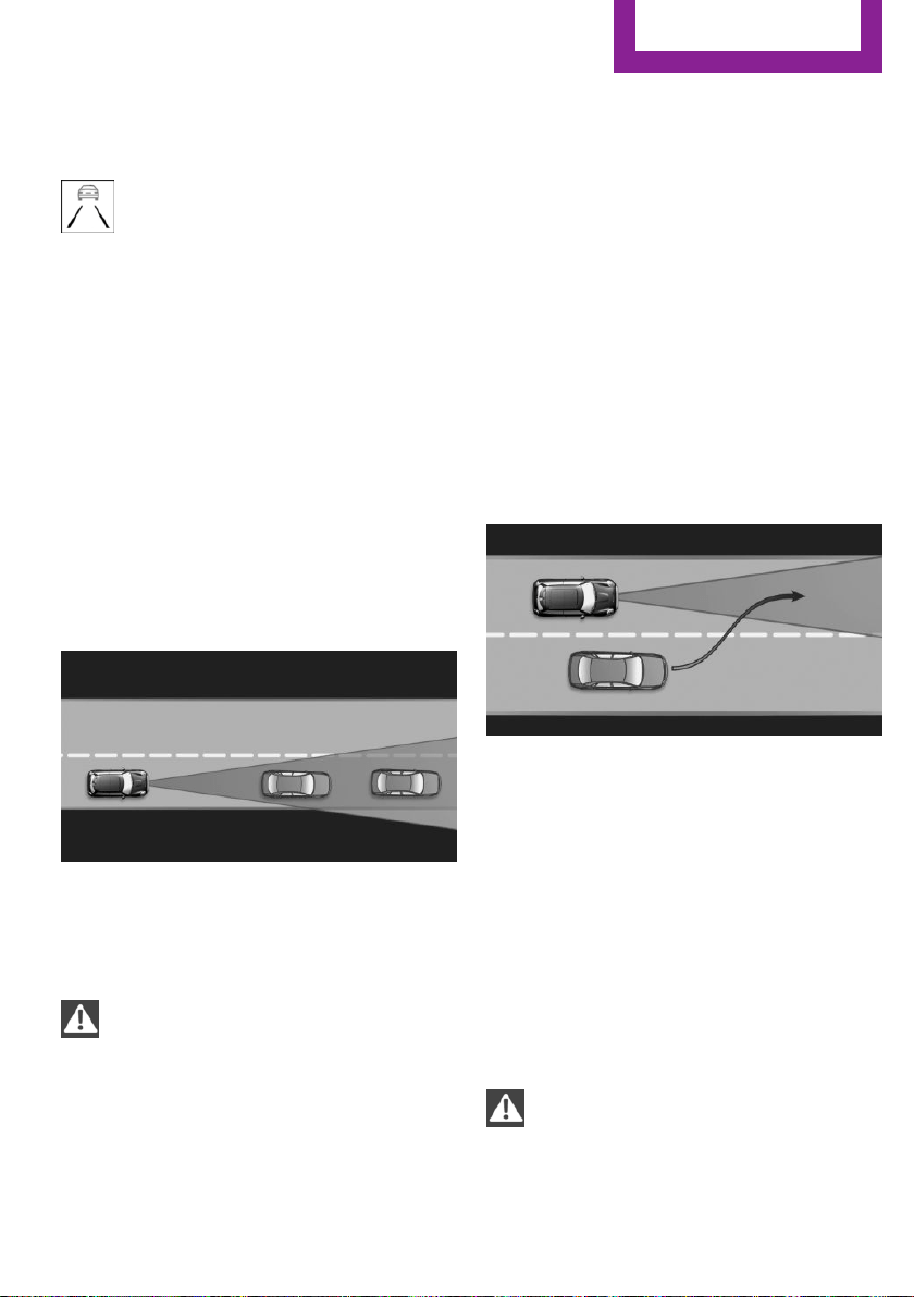
because the accelerator pedal is being pressed;
a vehicle was not detected.
Distance control is temporarily sup‐
pressed because the accelerator pedal
is being pressed; a vehicle was de‐
tected.
System limits
Speed range
The system is best used on well-constructed
roads. The system is functional at speeds be‐
ginning at approx. 20 mph/30 km/h.
The max. speed that can be set is
85 mph/140 km/h.
Comply with the legal speed limit and safety
distance in every situation when using the sys‐
tem.
Detection range
The detection capacity of the system and the
automatic braking capacity are limited.
Two-wheeled vehicles for instance might not
be detected.
WARNING
The system does not relieve from the per‐
sonal responsibility to correctly assess the traf‐
fic situation. Based on the limits of the system,
it cannot independently react to all traffic situa‐
tions. There is risk of an accident. Adjust the
driving style to the traffic conditions. Watch
traffic closely and actively interfere in the re‐
spective situations.◀
Deceleration
The system also does not decelerate in the fol‐
lowing situations:
▷ In case of pedestrians, cyclists or similar
slow road users.
▷ For red traffic lights.
▷ For cross traffic.
▷ For oncoming traffic.
▷ Unlit vehicles or vehicles with nonworking
lighting at night.
Swerving vehicles
A vehicle driving in front of you is not detected
until it is completely within the same lane as
your vehicle.
If a vehicle driving ahead of you suddenly
swerves into your lane, the system may not be
able to automatically restore the selected dis‐
tance. This also applies to major speed differ‐
ences to vehicles driving ahead of you, e.g.,
when rapidly approaching a truck. When a ve‐
hicle driving ahead of you is reliably detected,
the system requests that the driver intervene
by braking and carrying out evasive maneu‐
vers, if needed.
WARNING
The system does not relieve from the per‐
sonal responsibility to correctly assess the traf‐
fic situation. Based on the limits of the system,
it cannot independently react to all traffic situa‐
Seite 105
Driving comfort
CONTROLS
105
Online Edition for Part no. 01 40 2 963 307 - VI/15
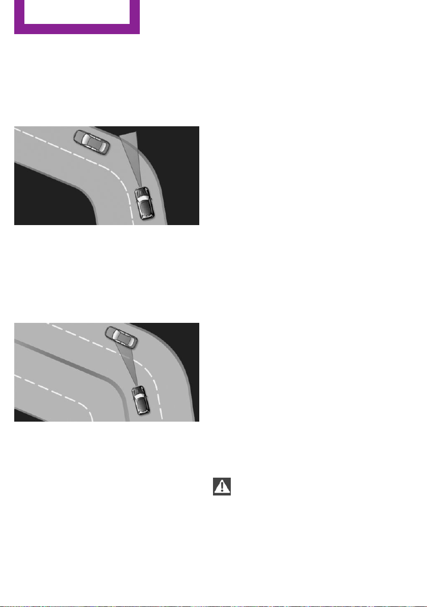
tions. There is risk of an accident. Adjust the
driving style to the traffic conditions. Watch
traffic closely and actively interfere in the re‐
spective situations.◀
Cornering
If the desired speed is too high for a curve, the
speed is reduced slightly, although curves can‐
not be anticipated in advance. Therefore, drive
into a curve at an appropriate speed.
In tight curves the system offers only restricted
detection where a vehicle ahead of you might
be detected late or not at all.
When you approach a curve the system may
briefly report vehicles in the next lane due to
the bend of the curve. If the system decelerates
you may compensate it by briefly accelerating.
After releasing the gas pedal the system is reac‐
tivated and controls speed independently.
Weather
In the event of unfavorable weather and light
conditions, e. g. if there is rain, snowfall, slush,
fog or glare, this may result in poorer recogni‐
tion of vehicles as well as short-term interrup‐
tions for vehicles that are already detected.
Drive attentively, and react to the current traffic
situation. If necessary, intervene actively, e.g.
by braking, steering or evading.
Malfunction
A Check Control message is displayed if the sys‐
tem fails or was automatically deactivated.
The system may not be fully functional in the
following situations:
▷ When an object was not correctly detected.
▷ In heavy fog, rain, sprayed water or snow‐
fall.
▷ In tight curves.
▷ If the field of view of the camera or the
front windshield are dirty or covered.
▷ When driving toward bright lights.
▷ Up to 20 seconds after the start of the en‐
gine, via the Start/Stop button.
▷ During calibration of the camera immedi‐
ately after vehicle delivery.
Cruise control
The concept
The system is functional at speeds beginning at
approx. 20 mph/30 km/h.
It maintains the speed that was set using the
control elements on the steering wheel.
The system brakes on downhill gradients if en‐
gine braking is insufficient.
Information
WARNING
The use of the system can lead to an in‐
creased risk of accidents in the following situa‐
tions:
▷ On winding roads.
▷ In heavy traffic.
Seite 106
CONTROLS
Driving comfort
106
Online Edition for Part no. 01 40 2 963 307 - VI/15
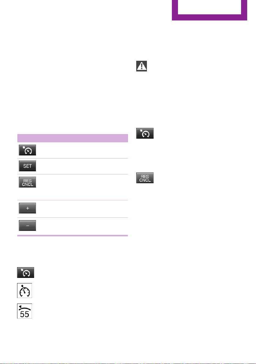
▷ On slippery roads, in fog, snow or rain, or
on a loose road surface.
There is risk of accidents or risk of property
damage. Only use the system if driving at con‐
stant speed is possible.◀
General information
Depending on the driving program, refer to
page 99, set, the characteristics of the cruise
control in particular areas can change.
Overview
Buttons on the steering wheel
Press button Function
Cruise control on/off
Store speed
Pausing cruise control
Continue cruise control with the
last setting
Increasing, maintaining or storing
the speed
Reducing, maintaining or storing
the speed
Controls
Switching on
Press button on the steering wheel.
The indicator lamp in the instrument
cluster lights up.
The current speed is adopted as the de‐
sired speed and is displayed with the
symbol in the instrument cluster.
Cruise control is active and maintains the set
speed.
DSC Dynamic Stability Control will be switched
on if needed.
Switch off
WARNING
The system does not relieve from the per‐
sonal responsibility to correctly assess the traf‐
fic situation. Based on the limits of the system,
it cannot independently react to all traffic situa‐
tions. There is risk of an accident. Adjust the
driving style to the traffic conditions. Watch
traffic closely and actively interfere in the re‐
spective situations.◀
Press button on the steering wheel.
The displays go out. The stored desired speed is
deleted.
Interrupting
When active, press the button on the
steering wheel.
The system is automatically interrupted in the
following situations:
▷ When the brakes are applied.
▷ If the clutch pedal is depressed for a few
seconds or released while a gear is not en‐
gaged.
▷ If the gear engaged is too high for the cur‐
rent speed.
▷ If selector lever position N is set.
▷ If DTC Dynamic Traction Control is activated
or DSC is deactivated.
▷ When DSC is actively controlling stability.
Seite 107
Driving comfort
CONTROLS
107
Online Edition for Part no. 01 40 2 963 307 - VI/15
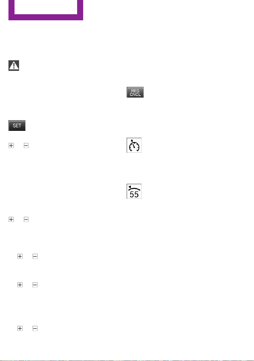
Maintaining, storing, and changing the
speed
Information
WARNING
The desired speed can be incorrectly ad‐
justed or called up by mistake. There is risk of
an accident. Adjust the desired speed to the
traffic conditions. Watch traffic closely and ac‐
tively interfere in the respective situations.◀
Maintaining/storing the speed
Press button.
Or
or button: press while the system is in‐
terrupted.
When the system is switched on, the current
speed is maintained and stored as the desired
speed.
This is displayed in the instrument cluster.
DSC Dynamic Stability Control will be switched
on if needed.
Changing the speed
or button: press repeatedly until the de‐
sired speed is set.
If active, the displayed speed is stored and the
vehicle reaches the stored speed when the
road is clear.
▷ or button: each time it is pressed to
the point of resistance, the desired speed
increases or decreases by approx.
1 mph/1 km/h.
▷ or button: each time it is pressed
past the point of resistance, the desired
speed increases or decreases by a maxi‐
mum of 5 mph/10 km/h.
The maximum speed that can be set de‐
pends on the vehicle.
▷ or button: pressing it to the resist‐
ance point and holding it there accelerates
or decelerates the vehicle without requiring
pressure on the accelerator pedal. After the
button is released, the vehicle maintains its
final speed. Pressing the switch beyond the
resistance point causes the vehicle to accel‐
erate more rapidly.
Continue cruise control
Press button on the steering wheel.
The stored speed is reached and maintained.
Displays in the instrument cluster
Indicator lamp
Depending on how the vehicle is equip‐
ped, the indicator lamp in the instru‐
ment cluster indicates whether the sys‐
tem is switched on.
Desired speed
The desired speed is displayed together
with the symbol.
▷ The indicator lights up green: the
system is active.
▷ The indicator lights up orange: the system
has been interrupted.
▷ No display: system is switched off.
If no speed is indicated, it is possible that the
conditions necessary for operation are not cur‐
rently fulfilled.
PDC Park Distance Con‐
trol
The concept
PDC supports you when parking. When you
slowly approach an object with the rear of your
car or with your front - depending on optional
features - a signal tone is sounded:
Seite 108
CONTROLS
Driving comfort
108
Online Edition for Part no. 01 40 2 963 307 - VI/15

General information
Ultrasound sensors in the bumpers measure
the distances from objects.
The maneuvering range, depending on obsta‐
cles and environmental conditions, is approx.
6 ft/2 m.
An acoustic warning is first given with the fol‐
lowing circumstances:
▷ By the front middle sensors and the two
corner sensors at approx. 24 in/60 cm.
▷ By the rear middle sensors at approx.
5 ft/1.50 m.
▷ When a collision is imminent
Information
Loud noises from outside and inside the vehicle
may prevent you from hearing the PDC's signal
tone.
WARNING
The system does not relieve from the per‐
sonal responsibility to correctly assess the traf‐
fic situation. There is risk of an accident. Adjust
the driving style to the traffic conditions. Watch
traffic and vehicle surroundings closely and ac‐
tively interfere in the respective situations.◀
WARNING
Due to high speeds when PDC is acti‐
vated, the warning can be delayed due to phys‐
ical circumstances. There is risk of injuries or
risk of property damage. Avoid approaching an
object too fast. Avoid driving off fast while PDC
is not yet active.◀
Overview
Button in the vehicle
PDC Park Distance Control
Ultrasound sensors
PDC sensors on the vehicle.
Functional requirements
To ensure full functionality:
▷ Do not cover sensors, e.g., with stickers, bi‐
cycle racks.
▷ Keep the sensors clean and free of ice.
To clean: when using high-pressure washers,
do not spray the sensors for long periods and
maintain a distance of at least 12 in/30 cm.
Switching on/off
Switching on automatically
PDC switches on automatically in the following
situations:
▷ If selector lever position R is engaged when
the engine is running.
▷ If, with the appropriate equipment, obsta‐
cles are detected behind or in front of the
vehicle by PDC and the speed is slower than
approx. 2.5 mph/4 km/h.
Seite 109
Driving comfort
CONTROLS
109
Online Edition for Part no. 01 40 2 963 307 - VI/15

You may turn off automatic activation via the
radio:
1.
Press button.
2. "Settings"
3. "Parking"
4. "Auto PDC"
5. Select setting.
Settings are stored for the profile currently
used.
Automatic deactivation during forward
travel
The system switches off when a certain driving
distance or speed is exceeded.
Switch the system back on if needed.
Switching on/off manually
Press button.
▷ On: the LED lights up.
▷ Off: the LED goes out.
Display
Signal tones
When approaching an object, an intermittent
sound indicates the position of the object. E. g.
if an object is detected to the left rear of the ve‐
hicle, a signal tone sounds from the left rear
speaker.
The shorter the distance to the object, the
shorter the intervals.
If the distance to a detected object is less than
approx. 10 in/25 cm, a continuous tone is
sounded.
If objects are located both in front of and to the
rear of the vehicle, an alternating continuous
signal is sounded.
The signal tone is switched off, when selector
lever position P is engaged on vehicles with
Steptronic transmission.
Volume
The ratio of the PDC signal tone volume to the
entertainment volume can be adjusted.
1. "Multimedia", "Radio" or
"Settings"
2. "Tone"
3. "Volume settings"
4. "PDC"
5. To adjust: turn the controller.
6. To store: press the controller.
Settings are stored for the profile currently
used.
System limits
Limits of ultrasonic measurement
Ultrasonic measuring might not function under
the following circumstances:
▷ For small children and animals.
▷ For persons with certain clothing, e.g.
coats.
▷ With external interference of the ultra‐
sound, e.g. from passing vehicles or loud
machines.
▷ When sensors are dirty, iced over, damaged
or out of position.
▷ Under certain weather conditions such as
high relative humidity, rain, snowfall, ex‐
treme heat or strong wind.
▷ With tow bars and trailer couplings of other
vehicles.
▷ With thin or wedge-shaped objects.
▷ With moving objects.
▷ With elevated, protruding objects such as
ledges or cargo.
▷ With objects with corners and sharp edges.
▷ With objects with a fine surface structure
such as fences.
▷ For objects with porous surfaces.
Seite 110
CONTROLS
Driving comfort
110
Online Edition for Part no. 01 40 2 963 307 - VI/15
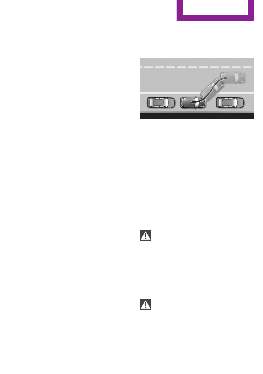
Low objects already displayed, e.g., curbs, can
move into the blind area of the sensors before
or after a continuous tone sounds.
False warnings
PDC may issue a warning under the following
conditions even though there is no obstacle
within the detection range:
▷ In heavy rain.
▷ When sensors are very dirty or covered with
ice.
▷ When sensors are covered in snow.
▷ On rough road surfaces.
▷ On uneven surfaces, such as speed bumps.
▷ In large buildings with right angles and
smooth walls, e.g., in underground garages.
▷ In automatic car washes.
▷ Through heavy pollution.
▷ Due to other ultrasound sources, e.g.,
sweeping machines, high pressure steam
cleaners or neon lights.
The malfunction is signaled by a continuous
tone alternating between the front and rear
speakers. As soon as the malfunction due
to other ultrasound sources is no longer
present, the system is again fully functional.
Malfunction
A Check Control message, refer to page 63, is
displayed in the instrument cluster.
PDC has failed. Have the system checked.
Parking assistant
The concept
This system assists the driver in parking parallel
to the road.
Ultrasound sensors measure parking spaces on
both sides of the vehicle.
The parking assistant calculates the best possi‐
ble parking line and takes control of steering
during the parking procedure.
When parking, also take note of the visual and
acoustic information issued by the PDC and the
parking assistant and react accordingly.
A component of the parking assistant is the
PDC Park Distance Control, refer to page 108.
Information
WARNING
The system does not relieve from the per‐
sonal responsibility to correctly assess the traf‐
fic situation. Based on the limits of the system,
it cannot independently react to all traffic situa‐
tions. There is risk of an accident. Adjust the
driving style to the traffic conditions. Watch
traffic closely and actively interfere in the re‐
spective situations.◀
CAUTION
The parking assistant can steer the vehi‐
cle over or onto curbs. There is risk of property
damage. Watch traffic closely and actively in‐
terfere in the respective situations.◀
Seite 111
Driving comfort
CONTROLS
111
Online Edition for Part no. 01 40 2 963 307 - VI/15
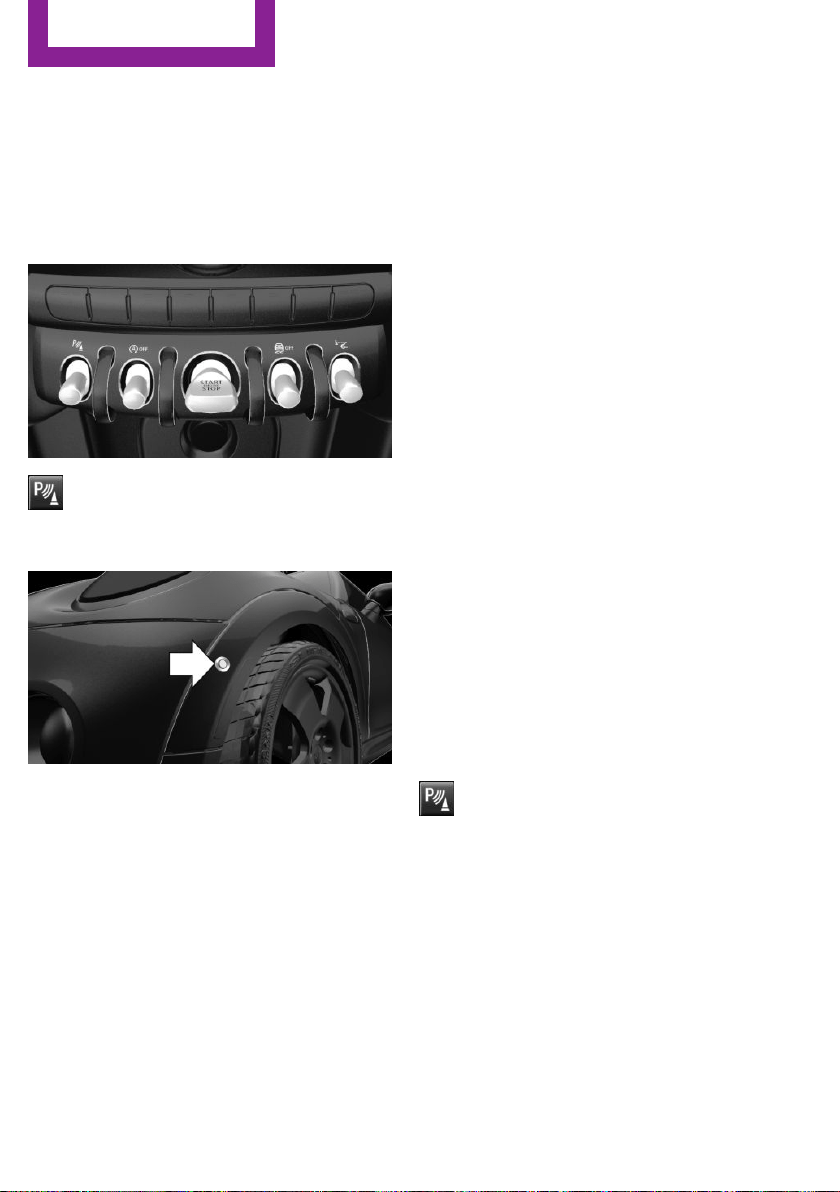
An engine that has been switched off by the
Auto Start Stop function is restarted automati‐
cally when the parking assistant is activated.
Overview
Button in the vehicle
Parking assistant
Ultrasound sensors
The ultrasound sensors for measuring parking
spaces are located on the wheel housing.
To ensure full functionality:
▷ Keep the sensors clean and free of ice.
▷ When using high-pressure washers, do not
spray the sensors for long periods and
maintain a distance of at least 12 in/30 cm.
▷ Do not put stickers over sensors.
Requirements
For measuring parking spaces
▷ Maximum speed while driving forward ap‐
prox. 22 mph/35 km/h.
▷ Maximum distance to row of parked vehi‐
cles: 5 ft/1.5 m.
Suitable parking space
▷ Gaps behind an object that has a min.
length of 5 ft/1.5 m.
▷ Gap between two objects with a minimum
length of approx. 5 ft/1.5 m.
▷ Min. length of gap between two objects:
your vehicle's length plus approx.
3.3 ft/1.0 m.
▷ Minimum depth: approx. 5 ft/1.5 m.
Regarding the parking procedure
▷ Doors and tailgate closed.
▷ Parking brake released.
▷ When parking in parking spaces on the
driver's side, the corresponding turn signal
must be set.
Switching on/off
Switching on with the button
Press button.
The LED lights up.
The current status of the parking space search
is indicated on the radio.
Parking assistant is activated automatically.
Switching on with reverse gear
Shift into reverse.
As soon as a suitable parking space is recog‐
nized by the system, the following query is dis‐
played on the radio display: "Start vehicle
parking?"
"OK": activate parking assistant.
Seite 112
CONTROLS
Driving comfort
112
Online Edition for Part no. 01 40 2 963 307 - VI/15
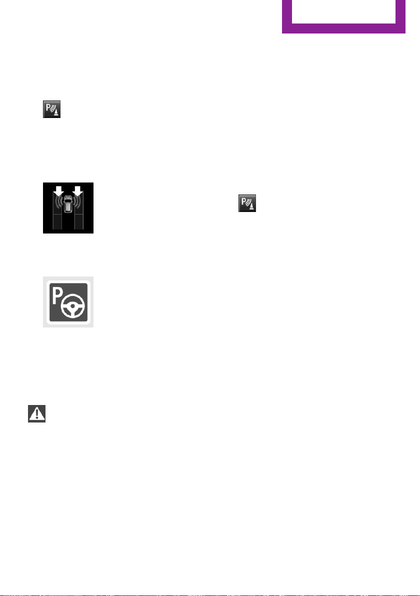
"Cancel": cancel parking assistant.
Switch off
The system can be deactivated as follows:
▷ Press button.
▷ Switch off the ignition.
Indicator of the radio display
System status
▷ Symbols, see arrows, on the
side of the vehicle illustrated.
Parking assistant is activated
and search for parking space
active.
▷ Suitable parking spaces are displayed next
to the vehicle symbol at the edge of the
road as on the display.
▷ The parking procedure is ac‐
tive. Steering control has
been taken over by system.
▷ Parking space search is always active
whenever the vehicle is moving forward
slow and straight, even if the system is de‐
activated.
Parking using the parking assistant
WARNING
The system does not relieve from the per‐
sonal responsibility to correctly assess the traf‐
fic situation. There is risk of an accident. Adjust
the driving style to the traffic conditions. Watch
traffic and vehicle surroundings closely and ac‐
tively interfere in the respective situations.◀
1.
Switch on the parking assistant and activate
it if needed.
The status of the parking space search is in‐
dicated on the display.
2. Follow the instructions on the display.
The best possible parking position will
come after gear change on the stationary
vehicle - wait for the automatic steering
wheel move.
The end of the parking procedure is indi‐
cated on the display.
3. Adjust the parking position yourself if
needed.
Interrupting manually
The parking assistant can be interrupted at any
time:
▷ Press button.
Interrupting automatically
The system is interrupted automatically in the
following situations:
▷ If the driver grasps the steering wheel or if
he takes over steering.
▷ If a gear is selected that does not match the
instruction on the display.
▷ If the vehicle speed exceeds approx.
6 mph/10 km/h.
▷ Possible on snow-covered or slippery road
surfaces.
▷ If a maximum number of parking attempts
or the time taken for parking is exceeded.
▷ If the Park Distance Control PDC displays
clearances that are too small.
▷ When switching into other functions of the
radio.
A Check Control message is displayed.
Resume
An interrupted parking procedure can be con‐
tinued if needed.
To do this, follow the instructions on the dis‐
play.
Seite 113
Driving comfort
CONTROLS
113
Online Edition for Part no. 01 40 2 963 307 - VI/15

System limits
No parking assistance
The parking assistant does not offer assistance
in the following situations:
▷ In tight curves.
Functional limitations
The system may not be fully functional in the
following situations:
▷ On bumpy road surfaces such as gravel
roads.
▷ On slippery ground.
▷ With accumulations of leaves/snow in the
parking space.
▷ With a mounted emergency wheel.
Limits of ultrasonic measurement
Ultrasonic measuring might not function under
the following circumstances:
▷ For small children and animals.
▷ For persons with certain clothing, e.g.
coats.
▷ With external interference of the ultra‐
sound, e.g. from passing vehicles or loud
machines.
▷ When sensors are dirty, iced over, damaged
or out of position.
▷ Under certain weather conditions such as
high relative humidity, rain, snowfall, ex‐
treme heat or strong wind.
▷ With tow bars and trailer couplings of other
vehicles.
▷ With thin or wedge-shaped objects.
▷ With moving objects.
▷ With elevated, protruding objects such as
ledges or cargo.
▷ With objects with corners and sharp edges.
▷ With objects with a fine surface structure
such as fences.
▷ For objects with porous surfaces.
Low objects already displayed, e.g., curbs, can
move into the blind area of the sensors before
or after a continuous tone sounds.
The parking assistant may identify parking
spaces that are not suitable for parking.
Malfunction
A Check Control message is displayed.
The parking assistant failed. Have the system
checked.
Seite 114
CONTROLS
Driving comfort
114
Online Edition for Part no. 01 40 2 963 307 - VI/15
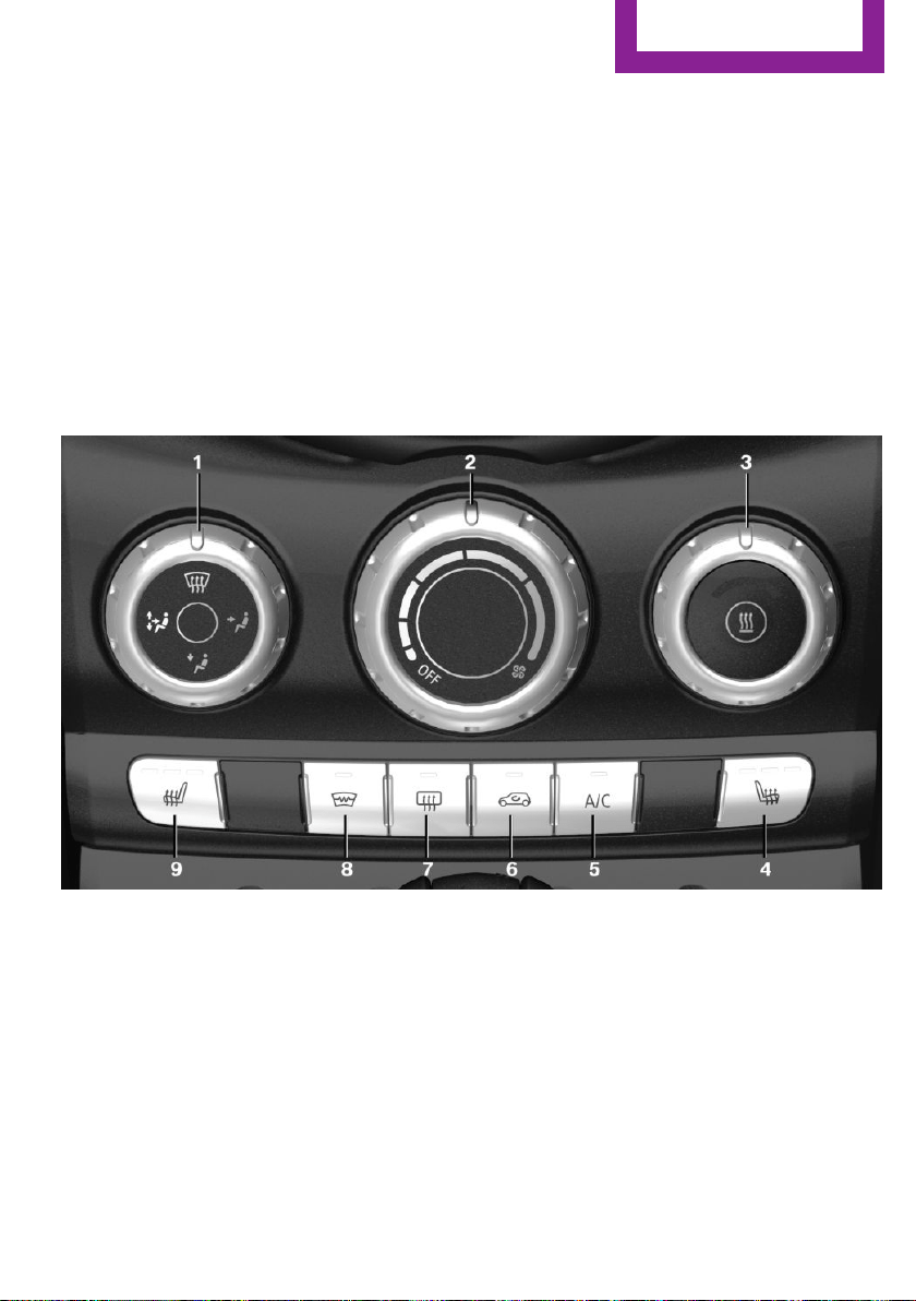
Climate control
Vehicle features and op‐
tions
This chapter describes all standard, country-
specific and optional features offered with the
series. It also describes features that are not
necessarily available in your car, e. g., due to
the selected options or country versions. This
also applies to safety-related functions and sys‐
tems. The respectively applicable country provi‐
sions must be observed when using the respec‐
tive features and systems.
Air conditioner
1 Vent settings
2 Air flow
3 Temperature
4 Seat heating, right 38
5 Cooling function
6 Recirculated-air mode
7 Rear window defroster
8 Windshield defroster
9 Seat heating, left 38
Seite 115
Climate control
CONTROLS
115
Online Edition for Part no. 01 40 2 963 307 - VI/15
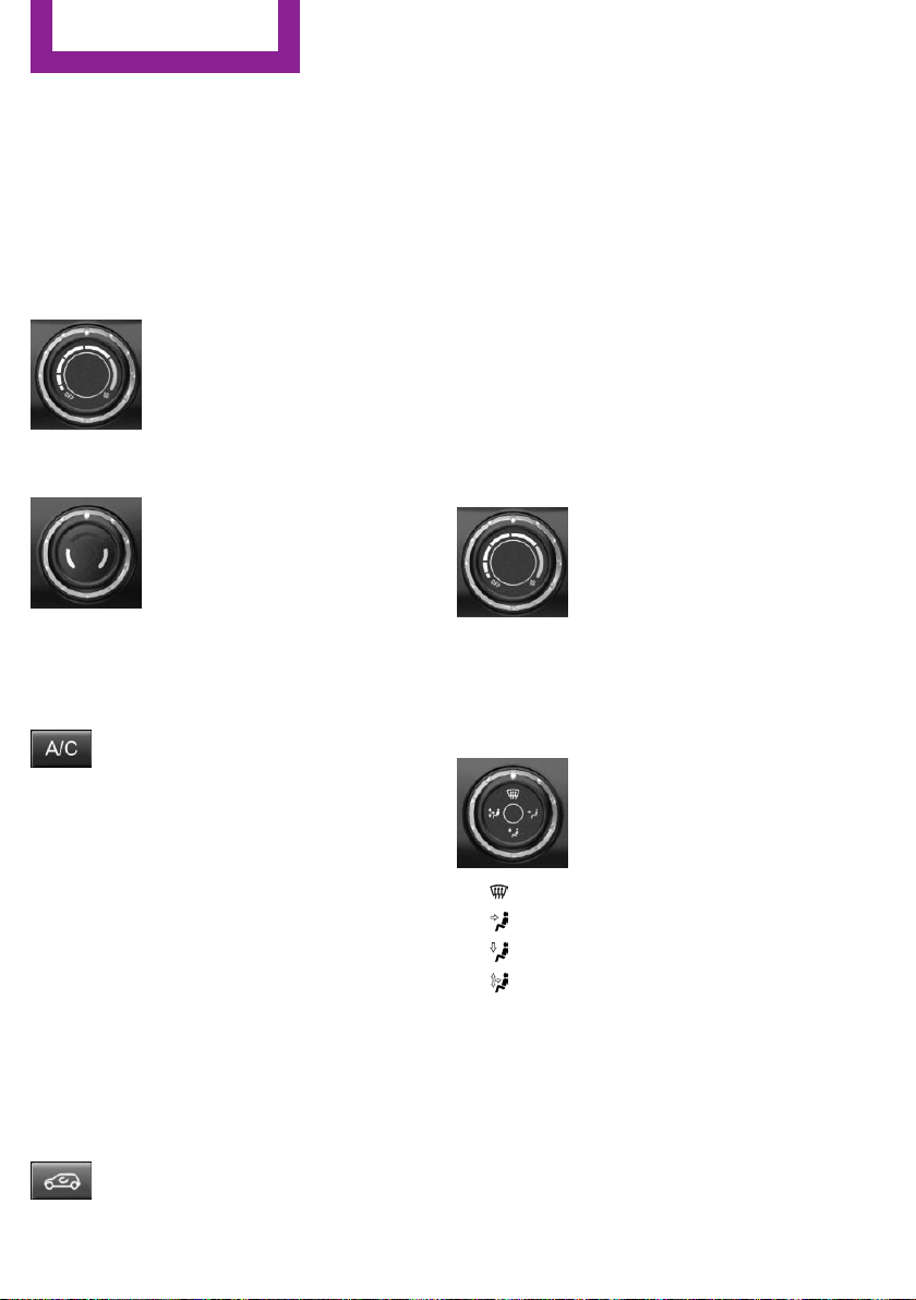
Climate control functions in detail
Switching the system on/off
Switching on
Set any air volume.
Switch off
Turn wheel for air quantity to the
left until the control switches off.
Temperature
Turn the ring to set the desired
temperature.
Cooling function
The car's interior can only be cooled with the
engine running.
Press button.
The air will be cooled and dehumidi‐
fied and, depending on the temperature set‐
ting, warmed again.
Depending on the weather, the windshield may
fog up briefly when the engine is started.
The air conditioner produces condensation wa‐
ter, refer to page 138, that will exit from below
the car.
Recirculated-air mode
You may respond to unpleasant odors or pollu‐
tants in the immediate environment by tempo‐
rarily suspending the supply of outside air. The
system then recirculates the air currently within
the vehicle.
Press button repeatedly to select an
operating mode:
▷ LED off: outside air flows in continuously.
▷ LED on, recirculated-air mode: the supply
of outside air into the vehicle is perma‐
nently blocked.
To prevent window condensation, recirculated
air mode switches off automatically after a cer‐
tain amount of time, depending on the external
temperature.
With constant recirculated-air mode, the air
quality in the car's interior deteriorates and the
fogging of the windows increases.
If the windows fog over, switch off recirculated-
air mode and increase the air flow, if needed.
Air flow, manual
Turn the ring to set the desired
air volume.
The higher the rate, the more ef‐
fective the heating or cooling will
be.
The air flow from the air conditioner may be re‐
duced automatically to save battery power.
Manual air distribution
Turn the wheel to select the de‐
sired program or the desired in‐
termediate setting.
▷ Windows.
▷ Upper body region.
▷ Footwell.
▷ Windows, upper body region, and foot‐
well.
Defrosts windows and removes
condensation
Direct the air distribution toward windows, in‐
crease the air flow and temperature, and, if
needed, use the cooling function.
Seite 116
CONTROLS
Climate control
116
Online Edition for Part no. 01 40 2 963 307 - VI/15
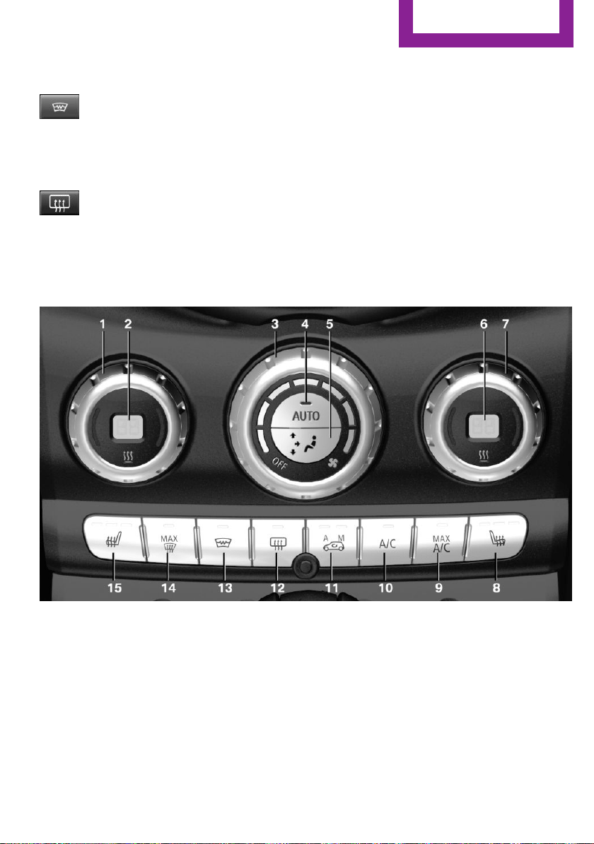
Windshield defroster
Press button.
The front window defroster switches
off automatically after a certain period of time.
Rear window defroster
Press button.
The rear window defroster switches off
automatically after a certain period of time.
When Green mode, refer to page 143, is acti‐
vated, the heater output is reduced.
Microfilter
In external and recirculated air mode the mi‐
crofilter filters dust and pollen from the air.
This filter should be replaced during scheduled
maintenance, refer to page 200, of your vehi‐
cle.
Automatic climate control
1 Temperature, left
2 Display
3 Air flow, AUTO intensity
4 AUTO program
5 Air distribution, manual
6 Display
7 Temperature, right
8 Seat heating, right 38
9 Maximum cooling
10 Cooling function
11 Automatic recirculated-air control/recircu‐
lated-air mode
12 Rear window defroster
13 Windshield defroster
14 Defrosts windows and removes condensa‐
tion
Seite 117
Climate control
CONTROLS
117
Online Edition for Part no. 01 40 2 963 307 - VI/15
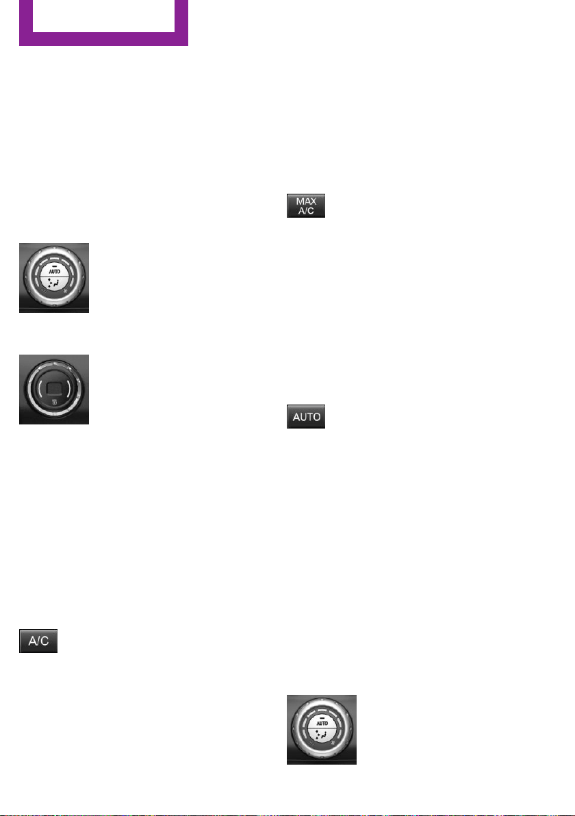
15 Seat heating, left 38
Climate control functions in detail
Switching the system on/off
Switching on
Set any air volume.
Switch off
Turn wheel for air quantity to the
left until the control switches off.
Temperature
Turn the ring to set the desired
temperature.
The automatic climate control reaches this
temperature as quickly as possible, if needed
by increasing the cooling or heating output,
and then keeps it constant.
Do not rapidly switch between different tem‐
perature settings. The automatic climate con‐
trol will not have sufficient time to adjust the
set temperature.
Cooling function
The car's interior can only be cooled with the
engine running.
Press button.
The air will be cooled and dehumidi‐
fied and, depending on the temperature set‐
ting, warmed again.
Depending on the weather, the windshield may
fog up briefly when the engine is started.
The cooling function is switched on automati‐
cally with the AUTO program.
When using the automatic climate control, con‐
densation water, refer to page 138, develops
that exits underneath the vehicle.
Maximum cooling
Press button.
The system is set to the lowest temper‐
ature, optimum air flow and air circulation
mode.
Air flows out of the vents to the upper body re‐
gion. The vents need to be open for this.
The function is available with external tempera‐
tures beyond approx. 32 ℉/0 ℃ and with the
engine running.
Adjust air flow with the program active.
AUTO program
Press button.
Air flow, air distribution and tempera‐
ture are controlled automatically.
Depending on the selected temperature, AUTO
intensity and outside influences, the air is di‐
rected to the windshield, side windows, upper
body, and into the footwell.
The cooling function, refer to page 118, and
the automatic recirculation control, refer to
page 119, are automatically also switched on
in the AUTO program.
To switch off the program: press the button
again or manually adjust the air distribution.
Intensity of the AUTO program
With the AUTO program activated, the auto‐
matic intensity control can be changed.
Turn the ring to set the desired
intensity.
Seite 118
CONTROLS
Climate control
118
Online Edition for Part no. 01 40 2 963 307 - VI/15
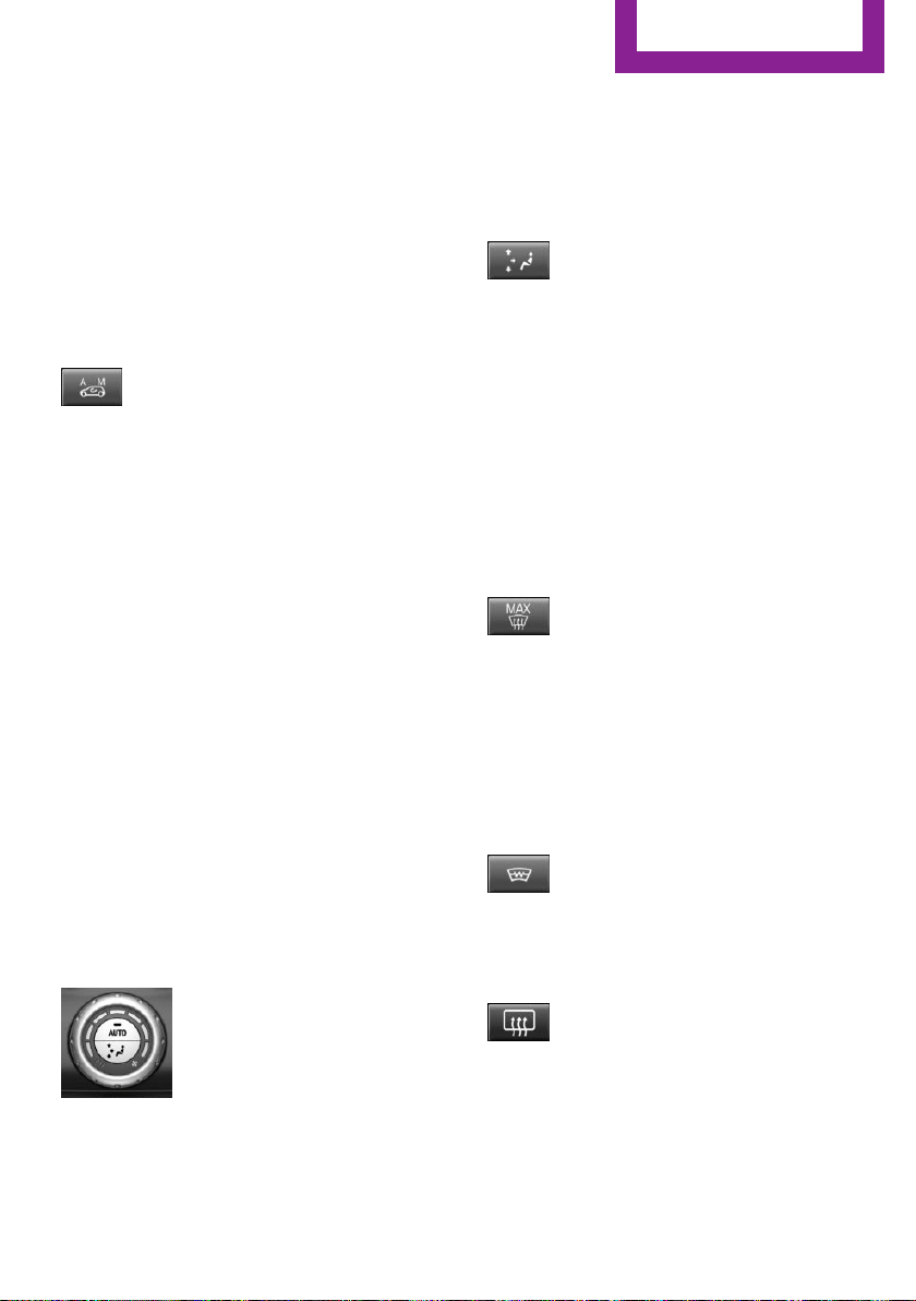
The selected intensity is displayed on the auto‐
matic climate control.
Automatic recirculated-air control/
recirculated-air mode
You may respond to unpleasant odors or pollu‐
tants in the immediate environment by tempo‐
rarily suspending the supply of outside air. The
system then recirculates the air currently within
the vehicle.
Press button repeatedly to select an
operating mode:
▷ LEDs off: outside air flows in continuously.
▷ Left LED on, automatic recirculated-air con‐
trol: a sensor detects pollutants in the out‐
side air and shuts off automatically.
▷ Right LED on, recirculated-air mode: the
supply of outside air into the vehicle is per‐
manently blocked.
To prevent window condensation, recirculated
air mode switches off automatically after a cer‐
tain amount of time, depending on the external
temperature.
With constant recirculated-air mode, the air
quality in the car's interior deteriorates and the
fogging of the windows increases.
If windows are fogged over, switch off the recir‐
culating mode and press the AUTO button.
Make sure that air can flow to the windshield.
Air flow, manual
To manually adjust air flow turn off AUTO pro‐
gram first.
Turn the ring to set the desired
air volume.
Automatic climate control displays the selected
amount of air flow.
The air flow of the automatic climate control
may be reduced automatically to save battery
power.
Manual air distribution
Press button repeatedly to select a
program:
▷ Upper body region.
▷ Upper body region and footwell.
▷ Footwell.
▷ Windows and footwell.
▷ Windows, upper body region, and footwell.
▷ Windows and upper body region.
▷ Windows.
Defrosts windows and removes
condensation
Press button.
Ice and condensation are quickly re‐
moved from the windshield and the front side
windows.
Adjust air flow with the program active.
If the windows fog over, also switch on the
cooling function or press the AUTO button.
Windshield defroster
Press button.
The front window defroster switches
off automatically after a certain period of time.
Rear window defroster
Press button.
The rear window defroster switches off
automatically after a certain period of time.
When Green mode, refer to page 143, is acti‐
vated, the heater output is reduced.
Seite 119
Climate control
CONTROLS
119
Online Edition for Part no. 01 40 2 963 307 - VI/15
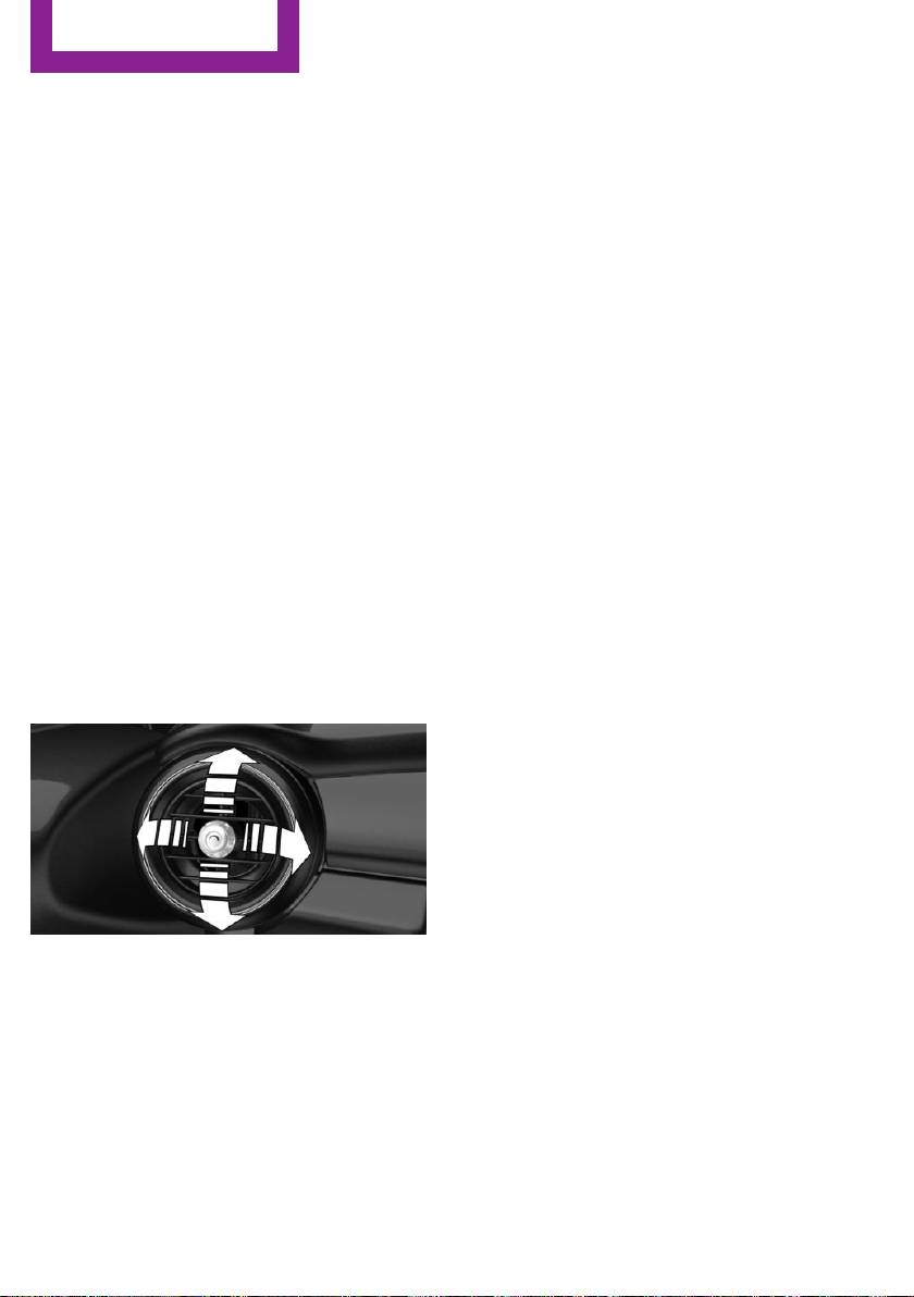
Microfilter/activated-charcoal filter
In external and recirculated air mode the mi‐
crofilter/activated charcoal filter filters dust,
pollen, and gaseous pollutants out of the air.
This filter should be replaced during scheduled
maintenance, refer to page 200, of your vehi‐
cle.
Ventilation
Setting
The air flow directions can be individually ad‐
justed:
▷ Direct ventilation:
The air flow is directly pointed onto the per‐
son. The air flow heats or cools noticeably,
depending on the adjusted temperature.
▷ Indirect ventilation:
If the vents are fully or partly closed, the air
is indirectly routed into the car's interior
Front ventilation
▷ Turn knob for continuous opening and clos‐
ing of the vents.
▷ Swivel the vents to alter the direction of the
vent flow, arrow.
Seite 120
CONTROLS
Climate control
120
Online Edition for Part no. 01 40 2 963 307 - VI/15
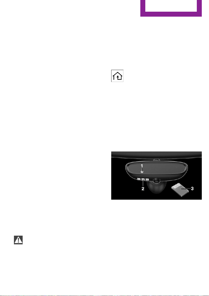
Interior equipment
Vehicle features and op‐
tions
This chapter describes all standard, country-
specific and optional features offered with the
series. It also describes features that are not
necessarily available in your car, e. g., due to
the selected options or country versions. This
also applies to safety-related functions and sys‐
tems. The respectively applicable country provi‐
sions must be observed when using the respec‐
tive features and systems.
Universal Integrated Re‐
mote Control
The concept
The Universal Integrated Remote Control can
operate up to 3 functions of remote-controlled
systems such as garage door drives or lighting
systems. The Universal Integrated Remote Con‐
trol replaces up to 3 different hand-held trans‐
mitters. To operate the remote control, the but‐
tons on the interior rearview mirror must be
programmed with the desired functions. The
hand-held transmitter for the particular system
is required in order to program the remote con‐
trol.
Before selling the vehicle, delete the stored
functions for the sake of security.
Information
WARNING
Body parts can be jammed when operat‐
ing remote-controlled systems, e.g. the garage
door, using the universal garage door opener.
There is risk of injuries or risk of property dam‐
age. Make sure that the area of movement of
the respective system is clear during program‐
ming and operation. Also follow the safety in‐
structions of the hand-held transmitter.◀
Compatibility
If this symbol is printed on the packag‐
ing or in the instructions of the system
to be controlled, the system is generally
compatible with the Universal Integrated Re‐
mote Control.
If you have any questions, please contact:
▷ A dealer’s service center or another quali‐
fied service center or repair shop.
▷ www.homelink.com on the Internet.
HomeLink is a registered trademark of Gentex
Corporation.
Overview
1 LED
2 Programmable keys
3 Hand-held transmitters of the system
Programming
General information
1.
Switch on the ignition.
2. Initial setup:
Press and hold the left and right button on
the interior rearview mirror simultaneously
for approximately 20 seconds until the LED
Seite 121
Interior equipment
CONTROLS
121
Online Edition for Part no. 01 40 2 963 307 - VI/15

on the interior rearview mirror flashes. This
erases all programming of the buttons on
the interior rearview mirror.
3. Hold the hand-held transmitter for the sys‐
tem to be controlled approx. 1 to 3 in/2.5
to 8 cm away from the buttons of the inte‐
rior rearview mirror. The required distance
depends on the manual transmitter.
4. Simultaneously press and hold the button
of the desired function on the hand-held
transmitter and the button to be program‐
med on the interior rearview mirror. The
LED on the interior rearview mirror will be‐
gin flashing slowly.
5. Release both buttons as soon as the LED
flashes more rapidly. The LED flashing
faster indicates that the button on the inte‐
rior rearview mirror has been programmed.
If the LED does not flash faster after at least
60 seconds, change the distance between
the interior rearview mirror and the hand-
held transmitter and repeat the step. Sev‐
eral more attempts at different distances
may be necessary. Wait at least 15 seconds
between attempts.
Canada: if programming with the hand-
held transmitter was interrupted, hold
down the interior rearview mirror button
and repeatedly press and release the hand-
held transmitter button for 2 seconds.
6.
To program other functions on other but‐
tons, repeat steps 3 to 5.
The systems can be controlled using the interior
rearview mirror buttons.
Special feature of the alternating-code
wireless system
If you are unable to operate the system after
repeated programming, please check if the sys‐
tem to be controlled features an alternating-
code system.
Read the system's operating manual, or press
the programmed button on the interior rear‐
view mirror longer. If the LED on the interior
rearview mirror starts flashing rapidly and then
stays lit constantly for 2 seconds, the system
features an alternating-code system. Flashing
and continuous illumination of the LED will re‐
peat for approximately 20 seconds.
For systems with an alternating-code system,
the Universal Integrated Remote Control and
the system also have to be synchronized.
Please read the operating manual to find out
how to synchronize the system.
Synchronizing is easier with the aid of a second
person.
To synchronize:
1.
Park the vehicle within range of the re‐
mote-controlled system.
2. Program the relevant button on the interior
rearview mirror as described.
3. Locate and press the synchronizing button
on the system being programmed. You
have approx. 30 seconds for the next step.
4. Hold down the programmed button on the
interior rearview mirror for approximately
3 seconds and then release it. If necessary,
repeat this step up to three times in order
to finish synchronization. Once synchroni‐
zation is complete, the programmed func‐
tion will be carried out.
Reprogramming individual buttons
1.
Switch on the ignition.
2. Press and hold the interior rearview mirror
button to be programmed.
3. As soon as the interior rearview mirror LED
starts flashing slowly, hold the hand-held
transmitter for the system to be controlled
approx. 1 to 3 in/2.5 to 8 cm away from the
buttons of the interior rearview mirror. The
required distance depends on the manual
transmitter.
Seite 122
CONTROLS
Interior equipment
122
Online Edition for Part no. 01 40 2 963 307 - VI/15
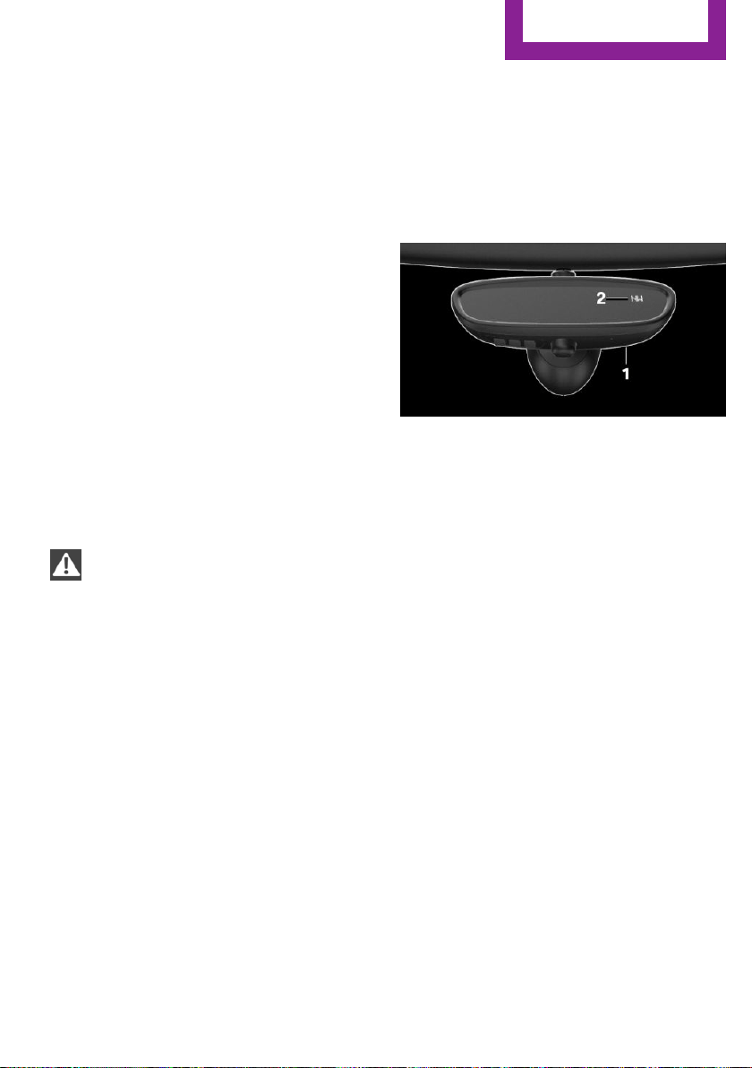
4. Likewise, press and hold the button of the
desired function on the hand-held trans‐
mitter.
5. Release both buttons as soon as the interior
rearview mirror LED flashes more rapidly.
The LED flashing faster indicates that the
button on the interior rearview mirror has
been programmed. The system can then be
controlled by the button on the interior
rearview mirror.
If the LED does not flash faster after at least
60 seconds, change the distance and re‐
peat the step. Several more attempts at dif‐
ferent distances may be necessary. Wait at
least 15 seconds between attempts.
Canada: if programming with the hand-
held transmitter was interrupted, hold
down the interior rearview mirror button
and repeatedly press and release the hand-
held transmitter button for 2 seconds.
Controls
WARNING
Body parts can be jammed when operat‐
ing remote-controlled systems, e.g. the garage
door, using the universal garage door opener.
There is risk of injuries or risk of property dam‐
age. Make sure that the area of movement of
the respective system is clear during program‐
ming and operation. Also follow the safety in‐
structions of the hand-held transmitter.◀
The system, such as the garage door, can be
operated using the button on the interior rear‐
view mirror while the engine is running or
when the ignition is started. To do this, hold
down the button within receiving range of the
system until the function is activated. The inte‐
rior rearview mirror LED stays lit while the wire‐
less signal is being transmitted.
Deleting stored functions
Press and hold the left and right button on the
interior rearview mirror simultaneously for ap‐
proximately 20 seconds until the LED flashes
rapidly. All stored functions are deleted. The
functions cannot be deleted individually.
Digital compass
Overview
1 Control button
2 Mirror display
Mirror display
The point of the compass is displayed in the
mirror when driving straight.
Operating concept
Various functions can be called up by pressing
the control button with a pointed object, such
as the tip of a ballpoint pen or similar object.
The following setting options are displayed in
succession, depending on how long the control
button is pressed:
▷ Pressed briefly: turns display on/off.
▷ 3 to 6 seconds: compass zone setting.
▷ 6 to 9 seconds: compass calibration.
▷ 9 to 12 seconds: left/right-hand steering
setting.
▷ 12 to 15 seconds: language setting.
Setting the compass zones
Sets the particular compass zones on the vehi‐
cle so that the compass operates correctly; re‐
fer to World map with compass zones.
Seite 123
Interior equipment
CONTROLS
123
Online Edition for Part no. 01 40 2 963 307 - VI/15
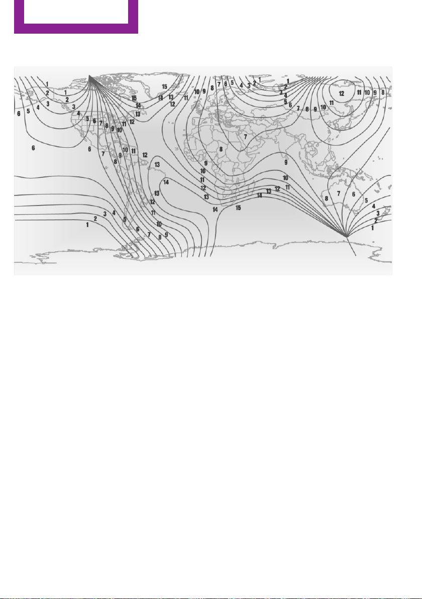
World map with magnetic zones
Procedure
1. Press and hold the control button for ap‐
prox. 3 to 4 seconds. The number of the set
compass zone appears in the mirror.
2. To change the zone setting, press the con‐
trol button quickly and repeatedly until the
number of the compass zone that corre‐
sponds with your location appears in the
mirror.
The set zone is stored automatically. The com‐
pass is ready for use again after approximately
10 seconds.
Calibrating the digital compass
The digital compass must be calibrated in the
event of the following:
▷ The wrong compass point is displayed.
▷ The point of the compass displayed does
not change despite changing the direction
of travel.
▷ Not all points of the compass are displayed.
Procedure
1. Make sure that there are no large metallic
objects or overhead power lines near the
vehicle and that there is sufficient room to
drive around in a circle.
2. Set the currently applicable compass zone.
3. Press and hold the control button for ap‐
prox. 6 to 7 seconds so that "C" appears on
the display. Next, drive in a complete circle
at least once at a speed of no more than
4 mph/7 km/h. If calibration is successful,
the "C" is replaced by the points of the
compass.
Left/right-hand steering
The digital compass is already set for right or
left-hand steering at the factory.
Setting the language
Press and hold the control button for approx.
12 to 13 seconds. Briefly press the control but‐
ton again to switch between English "E" and
German "O".
Seite 124
CONTROLS
Interior equipment
124
Online Edition for Part no. 01 40 2 963 307 - VI/15
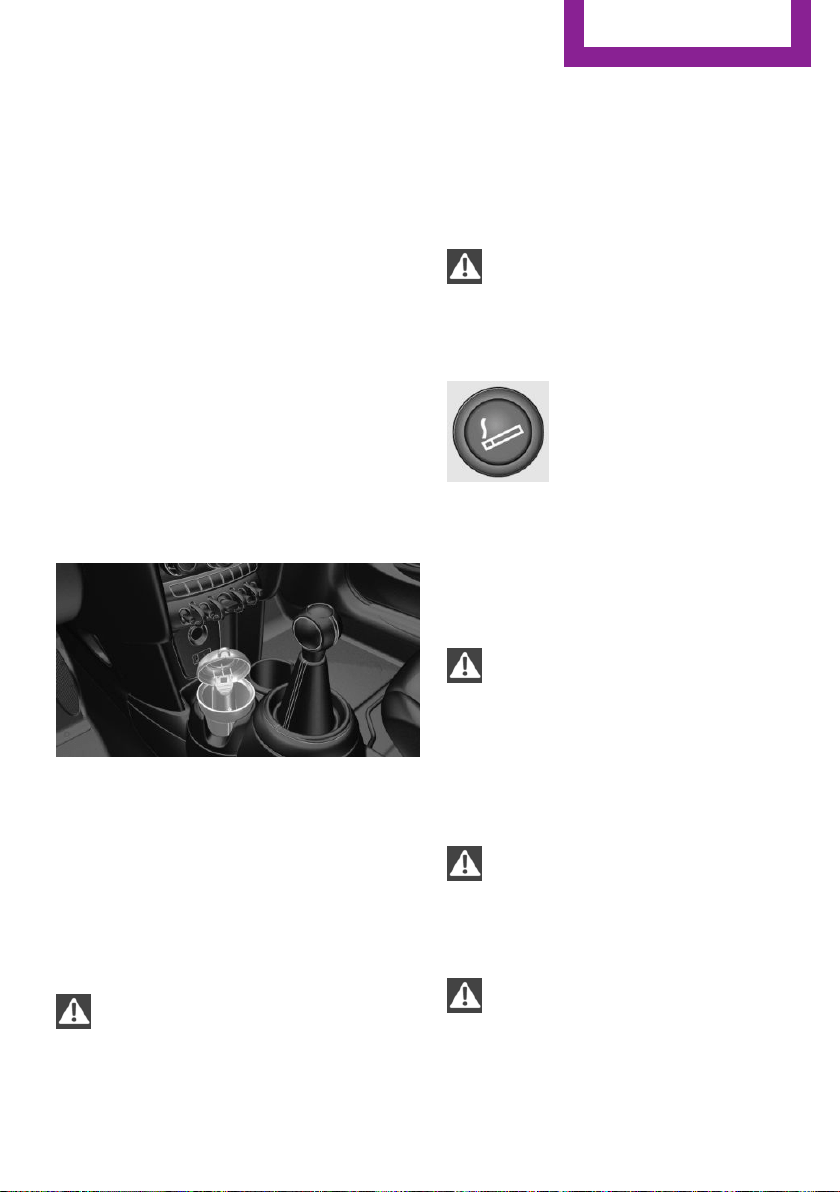
Settings are stored automatically after approxi‐
mately 10 seconds.
Sun visor
Glare shield
Fold the sun visor down or up.
Vanity mirror
A vanity mirror is located in the sun visor be‐
hind a cover. When the cover is opened, the
mirror lighting switches on.
Ashtray/cigarette
lighter
Overview
The ashtray is located in one of the frontal cup
holders, the cigarette lighter above it in the
center console.
Ashtray
In order to empty the ashtray, remove the ash‐
tray from the cupholder.
Lighter
WARNING
Contact with hot heating elements or the
hot socket of the cigarette lighter can cause
burns. Flammable materials can ignite if the
cigarette lighter falls down or is held against
the respective objects. There is risk of fire and
injuries. Hold the cigarette lighter on its handle.
Make sure that children do not use the ciga‐
rette lighter and do not burn themselves, e.g.
by carrying the remote control along when ex‐
iting the vehicle.◀
CAUTION
If metal objects fall into the socket, they
can cause a short circuit. There is risk of prop‐
erty damage. Replace the cigarette lighter or
socket cover again after using the socket.◀
Push in the lighter.
The lighter can be removed as
soon as it pops back out.
Connecting electrical de‐
vices
Information
CAUTION
Battery chargers for the vehicle battery
can work with high voltages and currents,
which means that the 12V on-board network
can be overloaded or damaged. There is risk of
property damage. Only connect battery charg‐
ers for the vehicle battery to the starting aid
terminals in the engine compartment.◀
CAUTION
If metal objects fall into the socket, they
can cause a short circuit. There is risk of prop‐
erty damage. Replace the cigarette lighter or
socket cover again after using the socket.◀
WARNING
Devices and cables in the unfolding area
of the airbags, e.g. portable navigation devices,
etc., can hinder the unfolding of the airbag or
be thrown around in the car's interior when un‐
folding. There is risk of injuries. make sure that
Seite 125
Interior equipment
CONTROLS
125
Online Edition for Part no. 01 40 2 963 307 - VI/15
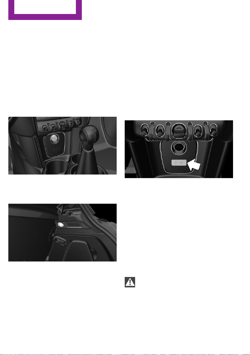
devices and cables are not in the airbag's area
of unfolding.◀
Sockets
Sockets can be used for the running electrical
devices with the engine running or with the ig‐
nition switched on. The total load of all sockets
must not exceed 140 watts at 12 volts.
Do not damage the socket by using non-com‐
patible connectors.
In the center console
Remove the cover or cigarette lighter.
In the trunk
The socket is located on the right side in the
trunk.
USB interface
The concept
Connection for USB devices with music files.
Information
Observe the following when connecting:
▷ Do not use force when plugging the con‐
nector into the USB interface.
▷ Do not connect devices such as fans or
lights to the USB interface.
▷ Do not connect any USB hard drives or USB
hubs.
▷ Do not use the USB interface for recharging
external devices.
Overview
The USB interface is located in the front of the
center console.
Cargo area
Cargo cover
General information
When the tailgate is opened, the cargo cover is
raised.
Information
WARNING
Loose objects in the car's interior can be
thrown into the car's interior while driving, e.g.
in the event of an accident or during braking
and evasive maneuvers. There is risk of injuries.
Secure loose objects in the car's interior.◀
Seite 126
CONTROLS
Interior equipment
126
Online Edition for Part no. 01 40 2 963 307 - VI/15
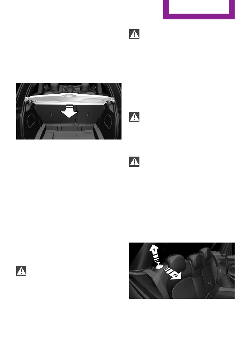
Removing
For storing bulky objects the cargo cover can
be removed.
1. Detach the left and right retaining straps at
the tailgate.
2. Pull the cargo cover out of the brackets on
the left and right.
Installing
1.
Slide the cargo cover forward horizontally
into the two side brackets until it audibly
engages.
2. Attach the left and right retaining straps at
the tailgate.
Enlarging the trunk
General information
The trunk can be enlarged by folding down the
rear seat backrest.
The rear backrest is divided 60–40. The back‐
rest of the left seat is connected to the backrest
center section.
Information
WARNING
Danger of jamming with folding down the
backrests. There is risk of injuries or risk of
property damage. Make sure that the area of
movement of the rear backrest is clear prior to
folding down.◀
WARNING
The stability of the child restraint system
is limited or compromised with incorrect seat
adjustment or improper installation of the child
seat. There is risk of injuries or danger to life.
Make sure that the child restraint system fits
securely against the backrest. If possible, adjust
the backrest tilt for all affected backrests and
correctly adjust the seats. Make sure that seats
and backrests are securely engaged. If possible,
adjust the height of the head restraints or re‐
move them.◀
WARNING
With a rear backrest that is not locked,
the protective function of the middle safety belt
is not guaranteed. There is risk of injuries or
danger to life. If you are using the middle safety
belt, lock the wider rear backrest.◀
WARNING
Body parts can be jammed when moving
the head restraint. There is risk of injuries.
Make sure that the area of movement is clear
when moving the head restraint.◀
Folding down side backrests
The rear seat backrests can be folded down
from the front or from the trunk.
Before the backrest is folded down, hook the
corresponding safety belt into the safety belt
on the side.
Pull the release upward and fold the backrest
toward the front.
Seite 127
Interior equipment
CONTROLS
127
Online Edition for Part no. 01 40 2 963 307 - VI/15
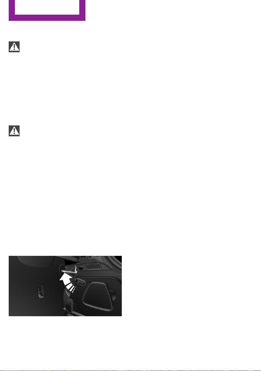
Folding back the backrest
WARNING
With an unlocked backrest, an unsecured
load can be thrown into the car's interior, e.g.
in case of an accident, braking or evasive ma‐
neuver. There is risk of injuries. Make sure that
the backrest engages into the locking after
folding it back.◀
Fold up the backrest and press it into the latch.
Make sure that the safety belt is not pinched.
Adjusting the backrest tilt
WARNING
The stability of the child restraint system
is limited or compromised with incorrect seat
adjustment or improper installation of the child
seat. There is risk of injuries or danger to life.
Make sure that the child restraint system fits
securely against the backrest. If possible, adjust
the backrest tilt for all affected backrests and
correctly adjust the seats. Make sure that seats
and backrests are securely engaged. If possible,
adjust the height of the head restraints or re‐
move them.◀
To transport bulky items, the trunk can be ex‐
panded by setting the backrests at a steeper
angle.
1.
Released the back rest, and tilt it forward.
2. Fold the frame up until it engages.
3. Fold back and latch the backrest.
Seite 128
CONTROLS
Interior equipment
128
Online Edition for Part no. 01 40 2 963 307 - VI/15
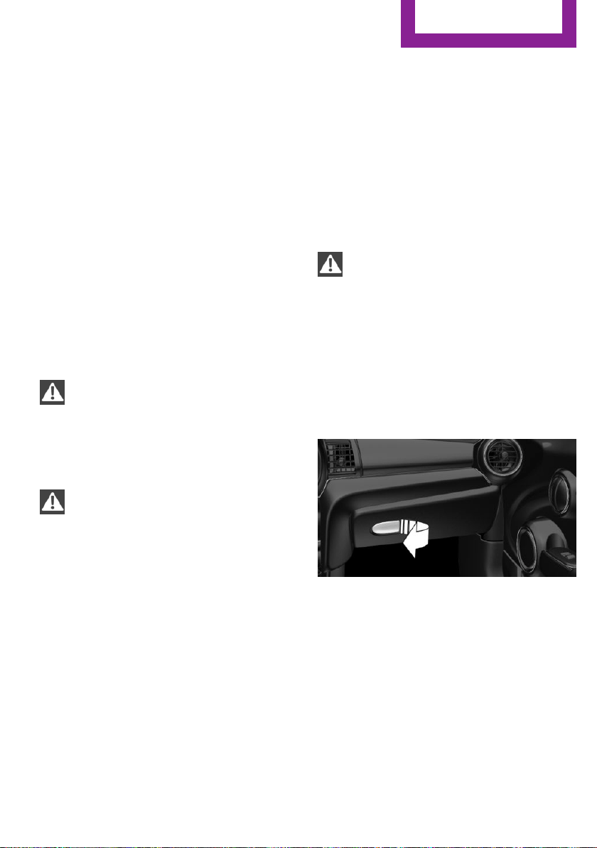
Storage compartments
Vehicle features and op‐
tions
This chapter describes all standard, country-
specific and optional features offered with the
series. It also describes features that are not
necessarily available in your car, e. g., due to
the selected options or country versions. This
also applies to safety-related functions and sys‐
tems. The respectively applicable country provi‐
sions must be observed when using the respec‐
tive features and systems.
Information
WARNING
Loose objects in the car's interior can be
thrown into the car's interior while driving, e.g.
in the event of an accident or during braking
and evasive maneuvers. There is risk of injuries.
Secure loose objects in the car's interior.◀
CAUTION
Anti-slip pads such as anti-slip mats can
damage the dashboard. There is risk of prop‐
erty damage. Do not use anti-slip pads.◀
Overview
The following storage compartments are avail‐
able in the vehicle interior:
▷ Storage compartment in front of the cu‐
pholders.
▷ Storage tray in the center console.
▷ Glove compartment on the front passenger
side.
▷ Storage compartment in the center arm‐
rest.
▷ Compartments in the doors.
▷ Pockets on the backrests of the front seats.
Glove compartment
Information
WARNING
Folded open, the glove compartment
protrudes in the car's interior. Objects in the
glove compartment can be thrown into the
car's interior while driving, e.g. in the event of
an accident or during braking and evasive ma‐
neuvers. There is risk of injuries. Always close
the glove compartment immediately after us‐
ing it.◀
Opening
Pull the handle.
The light in the glove compartment switches
on.
Closing
Fold up the cover.
Seite 129
Storage compartments
CONTROLS
129
Online Edition for Part no. 01 40 2 963 307 - VI/15
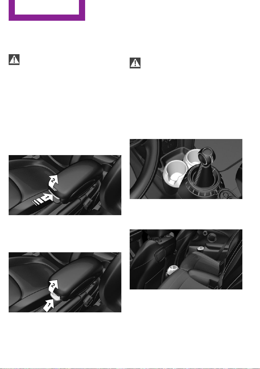
Compartments in the
doors
WARNING
Breakable object, e.g. glass bottle, can
break in the event of an accident. Broken glass
can be scattered in the car's interior. There is
risk of injuries. Do not stow any breakable ob‐
jects in the car's interior.◀
Center armrest
The center armrest contains a storage compart‐
ment.
Opening
Press button, arrow 1, and open center arm
rest upward, arrow 2.
Adjusting the height
Press button, arrow 1, and swing center arm
rest upward or downward into the desired
height, arrow 2.
Cupholders
Information
WARNING
Unsuitable containers in the cup holder
and hot beverages can damage the cup holder
and increase the risk of injuries in the event of
an accident. There is risk of injuries or risk of
property damage. Use light-weight, unbreaka‐
ble, and sealable containers. Do not transport
hot beverages. Do not force objects into the
cup holder.◀
Front
In the center console.
Rear
On 3-door models: in front of the rear seats and
in the and in the side armrests.
Seite 130
CONTROLS
Storage compartments
130
Online Edition for Part no. 01 40 2 963 307 - VI/15
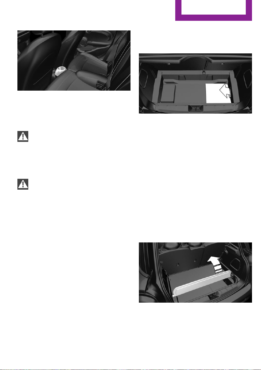
On 5-door models: in front of the rear seats.
Clothes hooks
WARNING
Clothing articles on the clothes hooks can
obstruct the view while driving. There is risk of
an accident. When suspending clothing articles
from the hooks, ensure that they will not ob‐
struct the driver's view.◀
WARNING
Improper use of the clothes hooks can
lead to a danger of objects flying about during
braking and evasive maneuvers. There is risk of
injuries and risk of property damage. Only hang
lightweight objects, e.g. clothing articles, from
the clothes hooks.◀
The clothes hooks are located above the side
windows in the rear.
Storage space under
cargo floor panel
Located under the cargo floor panel on the
right side is a trough for the onboard vehicle
tool kit.
To remove the onboard vehicle tool kit, fold the
right side of the cargo floor panel upward.
Variable trunk floor
With the variable trunk floor, the trunk can be
configured corresponding to transport require‐
ments. To do this, remove the trunk floor, and
insert it in the desired position.
Follow instructions on securing cargo, refer to
page 139.
Removing the cargo floor panel
On 5-door models: To change the position of
the cargo floor panel, first fold up the rear part
of the cargo floor panel.
Seite 131
Storage compartments
CONTROLS
131
Online Edition for Part no. 01 40 2 963 307 - VI/15
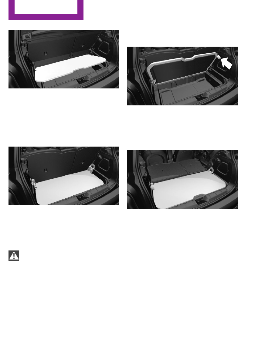
Grasp the cargo floor panel in the rear and fold
slightly upward. Next, pull it backward from the
supports.
The cargo floor panel can be removed from the
trunk above the tail lamps.
Lower position
▷ Larger objects can be transported.
▷ Space for smaller objects remains between
the fixed and variable trunk floor.
Folded up position
WARNING
Improper use of the variable cargo floor
panel can lead to a danger of objects flying
about during braking and evasive maneuvers.
There is risk of injuries and risk of property
damage.
▷ Do not use the variable cargo floor panel to
separate the cargo area and vehicle interior
in the sense of a partition net.
▷ Only use the variable cargo floor in the
folded-up position when the backrests are
folded up and locked.
▷ Always secure cargo against shifting, using
straps, belts and lashing eyes, e.g.◀
Fold up the cargo floor panel in the lower posi‐
tion and push it behind the locks, arrow.
You've reached the maximum cargo height.
Upper position
▷ With the backrests folded down, a long, flat
loading surface is produced.
▷ On 3-door models:
Maximum load in this position:
330 lbs/150 kg.
▷ On 5-door models:
Maximum load in this position:
441 lbs/200 kg.
▷ Space for objects remains between the
fixed and variable trunk floor.
Seite 132
CONTROLS
Storage compartments
132
Online Edition for Part no. 01 40 2 963 307 - VI/15

Seite 133
Storage compartments
CONTROLS
133
Online Edition for Part no. 01 40 2 963 307 - VI/15

DRIVE ME.
Online Edition for Part no. 01 40 2 963 307 - VI/15

AT A GLANCE
CONTROLS
DRIVING TIPS
ENTERTAINMENT
COMMUNICATION
MOBILITY
REFERENCE
Online Edition for Part no. 01 40 2 963 307 - VI/15

Things to remember when driving
Vehicle features and op‐
tions
This chapter describes all standard, country-
specific and optional features offered with the
series. It also describes features that are not
necessarily available in your car, e. g., due to
the selected options or country versions. This
also applies to safety-related functions and sys‐
tems. The respectively applicable country provi‐
sions must be observed when using the respec‐
tive features and systems.
Breaking-in period
General information
Moving parts need time to adjust to one an‐
other (break-in time).
The following instructions will help accomplish
a long vehicle life and good efficiency.
During break-in, do not use the Launch Control,
refer to page 61.
Engine, transmission, and axle drive
Up to 1,200 miles/2,000 km
Do not exceed the maximum engine and road
speed:
▷ For gasoline engine 4,500 rpm and
100 mph/160 km/h.
Avoid full load or kickdown under all circum‐
stances.
From 1,200 miles/2,000 km
The engine and vehicle speed can gradually be
increased.
Tires
Tire traction is not optimal due to manufactur‐
ing circumstances when tires are brand-new;
they achieve their full traction potential after a
break-in time.
Drive conservatively for the first
200 miles/300 km.
Brake system
Brakes require an initial break-in period of ap‐
prox. 300 miles/500 km to achieve optimal per‐
formance between brake discs and brake pads.
Drive moderately during this break-in period.
Clutch
The function of the clutch reaches its optimal
level only after a distance driven of approx.
300 miles/500 km. During this break-in period,
engage the clutch gently.
Following part replacement
The same break-in procedures should be ob‐
served if any of the components above-men‐
tioned have to be renewed in the course of the
vehicle's operating life.
General driving notes
Closing the tailgate
WARNING
An open tailgate protrudes from the vehi‐
cle and can endanger occupants and other traf‐
fic participants or damage the vehicle in the
event of an accident, braking or evasive ma‐
neuvers. In addition, exhaust fumes may enter
the vehicle interior. There is risk of injuries or
risk of property damage. Do not drive with the
tailgate open.◀
Seite 136
DRIVING TIPS
Things to remember when driving
136
Online Edition for Part no. 01 40 2 963 307 - VI/15

If driving with the tailgate open cannot be
avoided:
▷ Close all windows and the glass sunroof.
▷ Greatly increase the air flow from the vents.
▷ Drive moderately.
Hot exhaust system
WARNING
During driving operation, high tempera‐
tures can occur underneath the body, e.g.
caused by the exhaust gas system. If combusti‐
ble materials, such as leaves or grass, come in
contact with hot parts of the exhaust gas sys‐
tem, these materials can ignite. There is risk of
injuries or risk of property damage.
Do not remove the heat shields installed and
never apply undercoating to them. Make sure
that no combustible materials can come in con‐
tact with hot vehicle parts in driving operation,
idle or during parking. Do not touch the hot ex‐
haust system.◀
Mobile communication devices in the
vehicle
WARNING
Vehicle electronics and mobile phones
can influence one another. There is radiation
due to the send operations of mobile phones.
There is risk of injuries or risk of property dam‐
age. If possible, in the car's interior use only
mobile phones with direct connections to an
exterior antenna in order to exclude mutual
disturbance and deflect the radiation from the
car's interior.◀
Hydroplaning
On wet or slushy roads, a wedge of water can
form between the tires and road surface.
This phenomenon is referred to as hydroplan‐
ing. It is characterized by a partial or complete
loss of contact between the tires and the road
surface, ultimately undermining your ability to
steer and brake the vehicle.
Driving through water
CAUTION
When driving too quickly through too
deep water, water can enter into the engine
compartment, the electrical system or the
transmission. There is risk of property damage.
When driving through water, do not exceed the
maximum indicated water level and the maxi‐
mum speed for driving through water.◀
Drive through calm water only if it is not deeper
than 9.8 inches/25 cm and at this height, no
faster than walking speed, up to 3 mph/5 km/h.
Braking safely
Your vehicle is equipped with ABS as a standard
feature.
Applying the brakes fully is the most effective
way of braking in situations needed.
Steering is still responsive. You can still avoid
any obstacles with a minimum of steering ef‐
fort.
Pulsation of the brake pedal and sounds from
the hydraulic circuits indicate that ABS is in its
active mode.
Objects in the movement area around
pedals and floor area
WARNING
Objects in the driver's floor area can limit
the pedal distance or block a depressed pedal.
There is risk of an accident. Stow objects in the
vehicle such that they are secured and cannot
enter into the driver's floor area. Use floor mats
that are suitable for the vehicle and can be
safely attached to the floor. Do not use loose
floor mats and do not layer several floor mats.
Make sure that there is sufficient clearance for
the pedals. Ensure that the floor mats are se‐
curely fastened again after they were removed,
e.g. for cleaning.◀
Seite 137
Things to remember when driving
DRIVING TIPS
137
Online Edition for Part no. 01 40 2 963 307 - VI/15

Driving in wet conditions
When roads are wet, salted, or in heavy rain,
press brake pedal ever so gently every few
miles.
Ensure that this action does not endanger other
traffic.
The heat generated in this process helps dry
the brake discs and pads.
In this way braking efficiency will be available
when you need it.
Hills
WARNING
Light but consistent brake pressure can
lead to high temperatures, brakes wearing out
and possibly even brake failure. There is risk of
an accident. Avoid placing excessive stress on
the brake system.◀
WARNING
In idle or with the engine switched off,
safety-relevant functions are restricted or not
available anymore, e.g. braking effect of the
engine or braking force and steering support.
There is risk of an accident. Do not drive in idle
or with the engine switched off.◀
Drive long or steep downhill gradients in the
gear that requires least braking efforts. Other‐
wise the brakes may overheat and reduce
brake efficiency.
You can increase the engine's braking effect by
shifting down, going all the way to first gear, if
needed.
Brake disc corrosion
Corrosion on the brake discs and contamina‐
tion on the brake pads are furthered by:
▷ Low mileage.
▷ Extended periods when the vehicle is not
used at all.
▷ Infrequent use of the brakes.
Corrosion will built up when the maximum
pressure applied to the brake pads during brak‐
ing is not reached - thus discs don't get
cleaned.
Corrosion buildup on the brake discs will cause
a pulsating effect on the brakes in their re‐
sponse - generally that cannot be corrected.
Condensation under the parked vehicle
When using the automatic climate control, con‐
densation water develops collecting under‐
neath the vehicle.
These traces of water under the vehicle are
normal.
Ground clearance
CAUTION
If ground clearance is insufficient, there
might be contact with the front or rear spoiler
e.g. when driving over curbs or entering into
underground car parking garages. There is risk
of property damage. Ensure that there is suffi‐
cient ground clearance available.◀
Seite 138
DRIVING TIPS
Things to remember when driving
138
Online Edition for Part no. 01 40 2 963 307 - VI/15
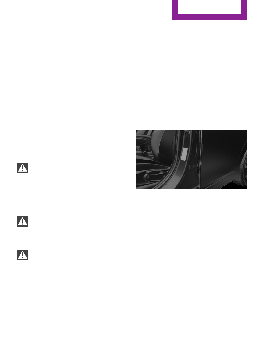
Loading
Vehicle features and op‐
tions
This chapter describes all standard, country-
specific and optional features offered with the
series. It also describes features that are not
necessarily available in your car, e. g., due to
the selected options or country versions. This
also applies to safety-related functions and sys‐
tems. The respectively applicable country provi‐
sions must be observed when using the respec‐
tive features and systems.
Information
WARNING
High gross weight can overheat the tires,
damage them internally, and cause a sudden
drop in tire inflation pressure. There is risk of an
accident. Pay attention to the permitted load
capacity of the tires and never exceed the per‐
mitted gross weight.◀
CAUTION
Fluids in the cargo area can cause dam‐
age. There is risk of property damage. Make
sure that no fluids leak in the cargo area.◀
WARNING
Loose objects in the car's interior can be
thrown into the car's interior while driving, e.g.
in the event of an accident or during braking
and evasive maneuvers. There is risk of injuries.
Secure loose objects in the car's interior.◀
Determining the load
limit
1. Locate the following statement on your ve‐
hicle’s placard:
▷ The combined weight of occupants and
cargo should never exceed XXX kg or
YYY lbs. Otherwise, damage to the ve‐
hicle and unstable driving situations
may result.
2. Determine the combined weight of the
driver and passengers that will be riding in
your vehicle.
3. Subtract the combined weight of the driver
and passengers from XXX kilograms or YYY
pounds.
4. The resulting figure equals the available
amount of cargo and luggage load ca‐
pacity.
For example, if the YYY amount equals
1,000 lbs and there will be four 150 lbs pas‐
sengers in your vehicle, the amount of
available cargo and luggage load capacity
is 400 lbs: 1,000 lbs minus 600 lbs =
400 lbs.
5. Determine the combined weight of luggage
and cargo being loaded on the vehicle.
That weight may not safely exceed the
available cargo and luggage load capacity
calculated in Step 4.
Seite 139
Loading
DRIVING TIPS
139
Online Edition for Part no. 01 40 2 963 307 - VI/15
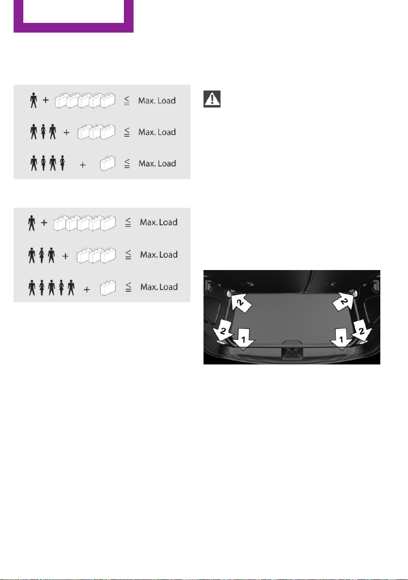
Load
On 3-door models
On 5-door models
The maximum load is the sum of the weight of
the occupants and the cargo.
The greater the weight of the occupants, the
less cargo that can be transported.
Stowing cargo
▷ Cover sharp edges and corners on the
cargo.
▷ Heavy cargo: stow as far forward as possi‐
ble, directly behind and at the bottom of
the rear passenger seat backrests.
▷ Very heavy cargo: when the rear seat is not
occupied, secure each of the outer safety
belts in the opposite buckle.
▷ If necessary, fold down the rear backrests
to stow cargo.
▷ Do not stack cargo above the top edge of
the backrests.
Securing cargo
Information
WARNING
Improperly stowed objects can shift and
be thrown into the car's interior, e.g. in the
event of an accident or during braking and eva‐
sive maneuvers. Vehicle occupants can be hit
and injured. There is risk of injuries. Stow and
secure objects and cargo properly.◀
▷ Smaller and lighter items: secure with re‐
taining straps or with draw straps.
▷ Larger and heavy objects: secure with
cargo straps.
Attach the cargo straps, retaining straps or
draw straps to the lashing eyes in the trunk.
Lashing eyes in the cargo area
Without storage compartment package: to se‐
cure the cargo there are two lashing eyes, ar‐
row 1, in the cargo area.
With storage compartment package: to secure
the cargo there are six lashing eyes, arrows 1
and 2, in the cargo area.
Roof-mounted luggage
rack
Information
Installation only possible with roof rack.
Roof racks are available as special accessories.
Seite 140
DRIVING TIPS
Loading
140
Online Edition for Part no. 01 40 2 963 307 - VI/15
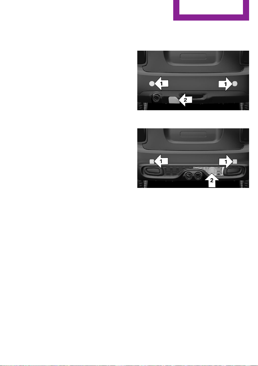
Securing
Follow the installation instructions of the roof
rack.
Loading
Because roof racks raise the vehicle's center of
gravity when loaded, they have a major effect
on vehicle handling and steering response.
Therefore, note the following when loading and
driving:
▷ Do not exceed the approved roof/axle
loads and the approved gross vehicle
weight.
▷ Be sure that adequate clearance is main‐
tained for tilting and opening the glass sun‐
roof.
▷ Distribute the roof load uniformly.
▷ The roof load should not extend past the
loading area.
▷ Always place the heaviest pieces on the
bottom.
▷ Secure the roof luggage firmly, e.g., tie with
ratchet straps.
▷ Do not let objects project into the opening
path of the tailgate.
▷ Drive cautiously and avoid sudden acceler‐
ation and braking maneuvers. Take corners
gently.
Rear luggage rack
General information
Installation only possible with rear luggage rack
preparation.
Rear racks are available as special accessories.
Information
Follow the installation instructions of the rear
luggage rack.
Drive cautiously and avoid sudden acceleration
and braking maneuvers. Take corners gently.
Securing
COOPER/COOPER D/ONE/ONE D
COOPER S/COOPER SD
The anchorage points, arrow 1, and the socket,
arrow 2, are located below the covers in the
bumper.
Remove the covers before installing the rear
luggage rack.
Power consumption
Before starting to drive, check the function of
the tail lamps of the rear luggage rack.
The rear luggage rack lights must not consume
more than:
▷ Turn signals: 42 watts per side.
▷ Rear lights: 50 watts per side.
▷ Brake lights: 84 watts in total.
▷ Rear fog lights: 42 watts in total.
▷ Backup lamp: 42 watts in total.
Seite 141
Loading
DRIVING TIPS
141
Online Edition for Part no. 01 40 2 963 307 - VI/15

Saving fuel
Vehicle features and op‐
tions
This chapter describes all standard, country-
specific and optional features offered with the
series. It also describes features that are not
necessarily available in your car, e. g., due to
the selected options or country versions. This
also applies to safety-related functions and sys‐
tems. The respectively applicable country provi‐
sions must be observed when using the respec‐
tive features and systems.
General information
Your vehicle contains advanced technology for
the reduction of fuel consumption and emis‐
sions.
Fuel consumption depends on a number of dif‐
ferent factors.
The implementation of certain measures, driv‐
ing style and regular maintenance can influ‐
ence fuel consumption and environmental im‐
pact.
Remove unnecessary
cargo
Additional weight increases fuel consumption.
Remove attached parts
following use
Remove roof or rear luggage racks which are
no longer required following use.
Attached parts on the vehicle impair the aero‐
dynamics and increase the fuel consumption.
Close the windows and
glass sunroof
Driving with the glass sunroof and windows
open results in increased air resistance and
raises fuel consumption.
Tires
General information
Tires can affect fuel consumption in various
ways, e.g., tire size may influence fuel con‐
sumption.
Check the tire inflation pressure
regularly
Check and, if needed, correct the tire inflation
pressure at least twice a month and before
starting on a long trip.
Low tire inflation pressure increases rolling re‐
sistance and thus raises fuel consumption and
tire wear.
Drive away without de‐
lay
Do not wait for the engine to warm-up while
the vehicle remains stationary. Start driving
right away, but at moderate engine speeds.
This is the fastest way for the cold engine to
reach its operating temperature.
Look well ahead when
driving
Avoid unnecessary acceleration and braking.
Seite 142
DRIVING TIPS
Saving fuel
142
Online Edition for Part no. 01 40 2 963 307 - VI/15

By maintaining a suitable distance to the vehi‐
cle driving ahead of you.
Driving smoothly and proactively reduces fuel
consumption.
Avoid high engine speeds
As a rule: driving at low engine speeds lowers
fuel consumption and reduces wear.
Use 1st gear to get the vehicle moving. Starting
with the 2nd gear, accelerate rapidly. When ac‐
celerating, shift up before reaching high engine
speeds.
When you reach the desired speed, shift into
the highest applicable gear and drive with the
engine speed as low as possible and at a con‐
stant speed.
The gear shift indicator, refer to page 68, of
your vehicle indicates the most fuel efficient
gear.
Use coasting conditions
When approaching a red light, take your foot
off the accelerator and let the vehicle coast to a
halt.
For going downhill take your foot off the accel‐
erator and let the vehicle roll.
The flow of fuel is interrupted while coasting.
Switch off the engine
during longer stops
Switch off the engine during longer stops, e.g.,
at traffic lights, railroad crossings or in traffic
congestion.
Auto Start/Stop function
The Auto Start/Stop function of your vehicle au‐
tomatically switches off the engine during a
stop.
If the engine is switched off and then restarted
rather than leaving the engine running con‐
stantly, fuel consumption and emissions are re‐
duced. Savings can begin within a few seconds
of switching off the engine.
In addition, fuel consumption is also deter‐
mined by other factors, such as driving style,
road conditions, maintenance or environmental
factors.
Switch off any functions
that are not currently
needed
Functions such as seat heating and the rear
window defroster require a lot of energy and
consume additional fuel, especially in city and
stop-and-go traffic.
Therefore, switch off these functions if they are
not actually needed.
Have maintenance car‐
ried out
Have vehicles maintained regularly to achieve
optimal vehicle efficiency and service life. MINI
recommends that maintenance work be per‐
formed by a MINI dealer’s service center.
For information on the MINI Maintenance Sys‐
tems, refer to page 200.
GREEN mode
The concept
The GREEN mode supports a driving style that
saves on fuel consumption. For this purpose,
the engine control and comfort features, e. g.
the climate control output, are adjusted.
For Steptronic transmission:
Seite 143
Saving fuel
DRIVING TIPS
143
Online Edition for Part no. 01 40 2 963 307 - VI/15

The Coasting driving condition is enabled under
certain conditions.
Under certain conditions the engine is auto‐
matically decoupled from the transmission in
selector lever position D. The vehicle continues
traveling with the engine idling to reduce fuel
consumption. Selector lever position D remains
engaged. An indicator provides information
about the distance traveled in Coasting mode.
In addition, context-sensitive instructions are
displayed to assist with an optimized fuel con‐
sumption driving style.
The achieved extended range is displayed in
the instrument cluster.
Overview
The system includes the following MINIMAL
functions and displays:
▷ GREEN bonus range, refer to page 144.
▷ GREEN tips driving instruction, refer to
page 145.
▷ GREEN climate control, refer to page 144.
▷ Coasting driving condition, refer to
page 145.
Activating GREEN mode
Turn Driving Dynamics Control to
the right until GREEN mode is
displayed in the instrument clus‐
ter.
Configuring GREEN mode
Via radio
1.
"Settings"
2. Select between "Driving mode" or "GREEN
Mode"
Configure the program.
GREEN tip
"GREEN speed warning":
Displays a reminder when the set GREEN mode
speed is exceeded.
GREEN climate control
"GREEN climate control":
Climate control is set to be fuel-efficient.
By making a slight change to the set tempera‐
ture, or adjusting the rate of heating or cooling
of the car's interior fuel consumption can be
economized.
The outputs of the seat heater and the exterior
Additionally heat output to seats and exterior
mirror is reduced.
Exterior mirror heat is available when outside
temperatures are very low.
Coasting
Fuel-efficiency can be optimized by disengag‐
ing the engine and Coasting, refer to page 145,
with the engine idling.
This function is only available in GREEN mode.
Display in the instrument cluster
GREEN bonus range
An adjusted driving style helps
you extend your driving range.
This may be displayed as the bo‐
nus range in the instrument clus‐
ter.
The bonus range is shown in the range display.
The bonus range is automatically reset every
time the vehicle is refueled.
▷ Green display: efficient driving style.
▷ Gray display: adjust driving style, e. g. by
backing off the accelerator pedal.
Seite 144
DRIVING TIPS
Saving fuel
144
Online Edition for Part no. 01 40 2 963 307 - VI/15
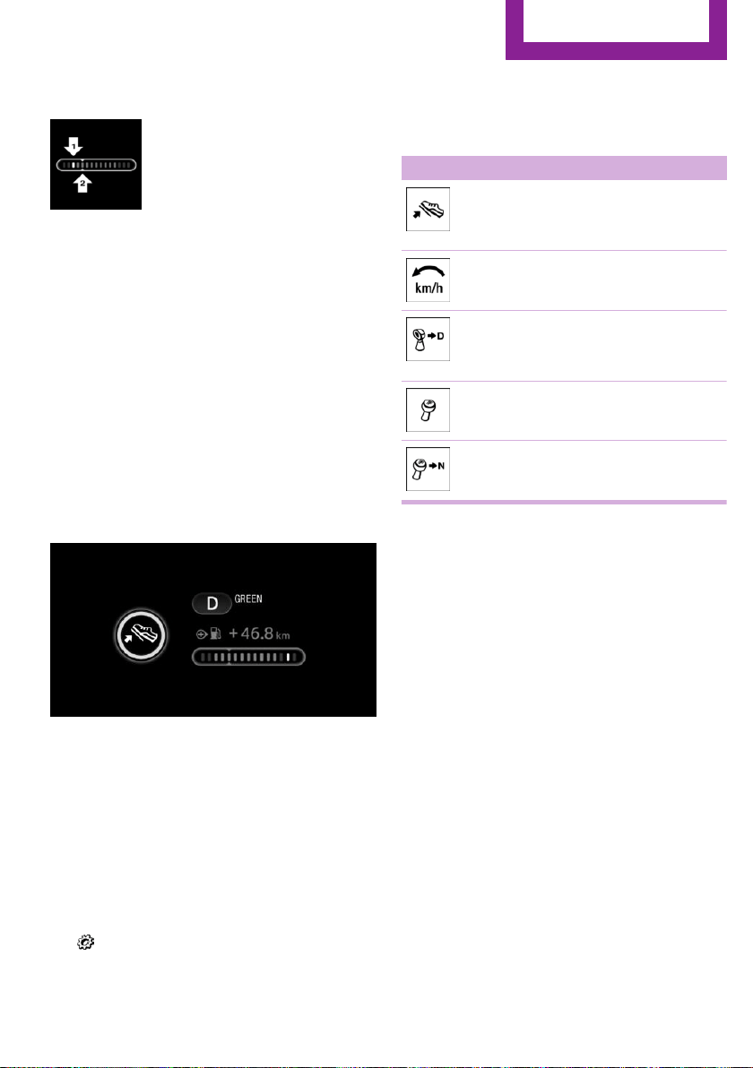
Driving style
A bar display in the instrument
cluster indicates your current
driving efficiency.
Mark in the left area, arrow 1:
display for energy recovered by
coasting or when braking.
Mark in the right area, arrow 2: display when
accelerating.
Your driving style's efficiency is shown by the
bar's color:
▷ Green display: efficient driving style as long
as the mark moves within the green range.
▷ Gray display: adjust driving style, e. g. by
backing off the accelerator pedal.
The display switches to green as soon as all
conditions for fuel-efficiency-optimized driving
are met.
GREEN tip driving instruction
Instructions tell you to switch to a more fuel-ef‐
ficient driving style when you back off the ac‐
celerator.
Information
The driving style display and GREEN mode tips
in the instrument cluster appear when the
GREEN mode display is activated.
Activating driving style and GREEN mode tips:
1.
"Settings"
2. "Instrument cluster"
3. "GREEN Info"
GREEN tip symbols
An additional symbol and text instructions are
displayed.
Symbol Measure
For efficient driving back off the ac‐
celerator or delay accelerating to al‐
low time to assess road conditions.
Reduce speed to the selected GREEN
speed.
Steptronic transmission: switch from
M/S to D or avoid manual shift inter‐
ventions.
Manual transmission: follow shifting
instructions.
Manual transmission: engage neutral
for engine stop.
Coasting
The concept
The system helps to conserve fuel.
To do this, under certain conditions the engine
is automatically decoupled from the transmis‐
sion when selector lever position D is set. The
vehicle continues traveling with the engine
idling to reduce fuel consumption. Selector
lever position D remains engaged.
This driving condition is referred to as coasting.
As soon as the brake or accelerator pedal is de‐
pressed, the engine is automatically coupled to
the transmission again.
Information
Coasting is a component of the GREEN driving
mode, refer to page 143.
Coasting is automatically activated when
GREEN mode is called via the Driving Dynamics
Control, refer to page 99.
Seite 145
Saving fuel
DRIVING TIPS
145
Online Edition for Part no. 01 40 2 963 307 - VI/15

The function is available in a certain speed
range.
A proactively driving style helps the driver to
use the function as often as possible and sup‐
ports the fuel-conserving effect of coasting.
Safety mode
The function is not available under one of the
following conditions.
▷ DSC OFF or TRACTION activated.
▷ Driving in the dynamic limit range and on
steep uphill or downhill grades.
▷ Battery charge status temporarily too low
or vehicle electrical system drawing exces‐
sive current.
▷ Cruise control activated.
Functional requirements
In GREEN mode, this function is available in a
speed range from approximately 30 mph, ap‐
prox. 50 km/h to 100 mph, approx. 160 km/h,
if the following conditions are met:
▷ Accelerator pedal and brake pedal are not
operated.
▷ The selector lever is in selector lever posi‐
tion D.
▷ Engine and transmission are at operating
temperature.
Display
Display in the instrument cluster
The mark in the bar display be‐
low the tachometer is high‐
lighted green and appears at the
zero point. The tachometer ap‐
proximately indicates idle speed.
Deactivating the system manually
The function can be deactivated via the radio,
e.g., to use the braking effect of the engine
when traveling downhill.
1. "Settings"
2. Select between "Driving mode" or "GREEN
Mode"
3. "Coasting"
Settings are saved for the profile currently be‐
ing used.
Seite 146
DRIVING TIPS
Saving fuel
146
Online Edition for Part no. 01 40 2 963 307 - VI/15

Seite 147
Saving fuel
DRIVING TIPS
147
Online Edition for Part no. 01 40 2 963 307 - VI/15
ROCK ME.
Online Edition for Part no. 01 40 2 963 307 - VI/15

AT A GLANCE
CONTROLS
DRIVING TIPS
ENTERTAINMENT
COMMUNICATION
MOBILITY
REFERENCE
Online Edition for Part no. 01 40 2 963 307 - VI/15

Tone
Vehicle features and op‐
tions
This chapter describes all standard, country-
specific and optional features offered with the
series. It also describes features that are not
necessarily available in your car, e. g., due to
the selected options or country versions. This
also applies to safety-related functions and sys‐
tems. The respectively applicable country provi‐
sions must be observed when using the respec‐
tive features and systems.
General information
Settings are stored for the profile, refer to
page 24, currently used.
Treble, bass, balance,
and fader
General information
▷ "Treble": treble adjustment.
▷ "Bass": depth adjustment.
▷ "Balance": left/right volume distribution.
▷ "Fader": front/rear volume distribution.
Adjusting treble, bass, balance, and
fader
1.
"Settings", "Radio" or
"Media"
2. "Tone"
3. Select the desired tone settings.
4. Set the desired value.
Volume
General information
▷ "Speed volume": speed-dependent volume
control.
▷ "PDC": volume of the PDC signal compared
to the entertainment sound output.
▷ "Gong": volume of the signal, such as the
safety belt reminder, compared to the en‐
tertainment sound output.
▷ "Microphone": volume of the microphone
during a phone call.
▷ "Loudspeak.": volume of the loudspeakers
during a phone call.
The following volumes are only stored for the
respective paired telephone:
"Microphone", "Loudspeak.".
Adjusting
1.
"Settings", "Radio" or
"Media"
2. "Tone"
3. "Volume settings"
4. Select the desired volume setting.
5. Set the desired value.
Resetting the tone set‐
tings
1.
"Settings", "Radio" or
"Media"
2. "Tone"
3. "Reset"
Seite 150
ENTERTAINMENT
Tone
150
Online Edition for Part no. 01 40 2 963 307 - VI/15
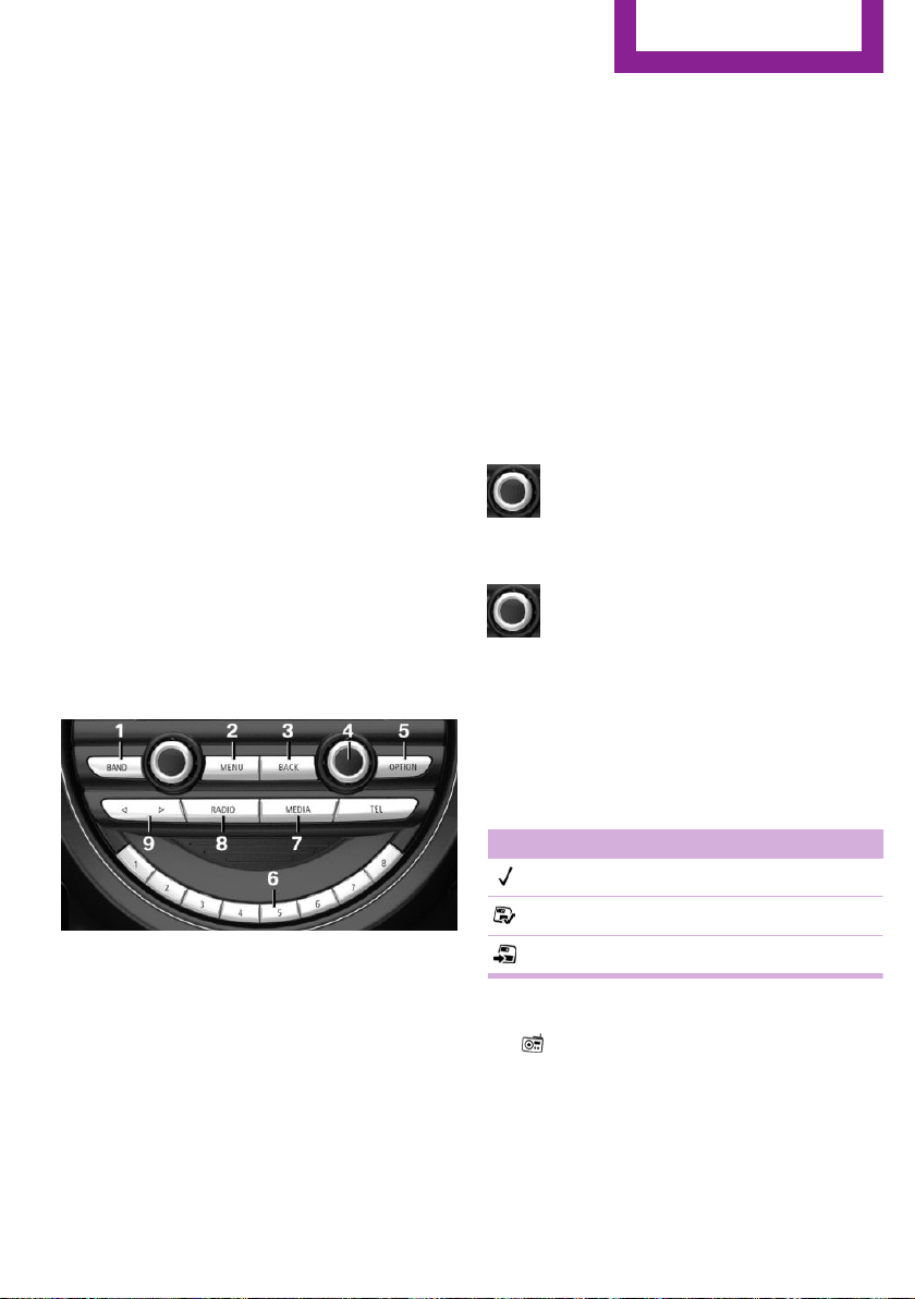
Radio
Vehicle features and op‐
tions
This chapter describes all standard, country-
specific and optional features offered with the
series. It also describes features that are not
necessarily available in your car, e. g., due to
the selected options or country versions. This
also applies to safety-related functions and sys‐
tems. The respectively applicable country provi‐
sions must be observed when using the respec‐
tive features and systems.
General information
Settings are stored for the profile, refer to
page 24, currently used.
Overview
1 Change waveband
2 Opening the main menu
3 Menu level back
4 Selecting menu items
▷ Turn: highlight the menu item in the
display or adjust the value.
▷ Press: select the highlighted menu item
or store the setting.
5 Open the options for the respective menu
6 Programmable memory buttons
7 "Media": open the menu
8 "Radio": open the menu
9 Changing the station
Sound output
Switching on/off
If the ignition is switched off: press the
left button.
Muting
If the ignition is switched on or the en‐
gine is running: press the left button.
AM/FM station
General information
A list of the stations that can be received for the
FM and AM wavelengths is displayed.
Symbol Meaning
Station is played.
Station is saved.
Station can be saved.
Selecting a station
1.
"Radio"
2. "FM" or "AM"
3. Select a station.
Seite 151
Radio
ENTERTAINMENT
151
Online Edition for Part no. 01 40 2 963 307 - VI/15

Selecting a station manually
1. "Radio"
2. "FM" or "AM"
3. "Manual search ( )"
4. Turn the right-hand knob until the desired
frequency is displayed.
Changing the station
About the radio:
Press button.
Via the buttons on the steering wheel:
Press button.
The next station with reception or stored sta‐
tion is played. If traffic bulletins are activated,
the next traffic information station is played.
About the radio:
Press and hold this button.
Via the buttons on the steering wheel:
Press and hold this button.
The waveband is traversed. After the button is
released, the next station with reception is
played.
Storing a station
1.
"Radio"
2. "FM" or "AM"
3. Select a station.
4. Press the right button.
5. Select the memory location.
The stations can also be stored on the Favorites
buttons, refer to page 153.
Renaming a station
When storing a station with RDS signal, the RDS
information transferred during storing is ac‐
cepted as the station name. This name can be
changed.
1. Select the station that is to be renamed.
2.
Press button.
3. "Rename to:"
If necessary, wait until the desired name
appears.
4. Press the right-hand knob to store this
name.
Displaying additional information
If a radio station broadcasts radio text or radio
text plus, this information can be displayed,
e.g., the track or the performer of the music.
Availability, content and sequence are set by
the radio station.
1.
"Radio"
2. "FM" or "AM"
3.
Press button.
4. "Station info"
RDS Radio Data System
The concept
RDS broadcasts additional information, such as
the station name, in the FM wave band.
When playing a station with multiple frequen‐
cies, the system automatically switches to the
frequency with the best reception, if needed.
Switching on/off
It is recommended to switch on RDS
1.
"Radio"
2. "FM"
Seite 152
ENTERTAINMENT
Radio
152
Online Edition for Part no. 01 40 2 963 307 - VI/15
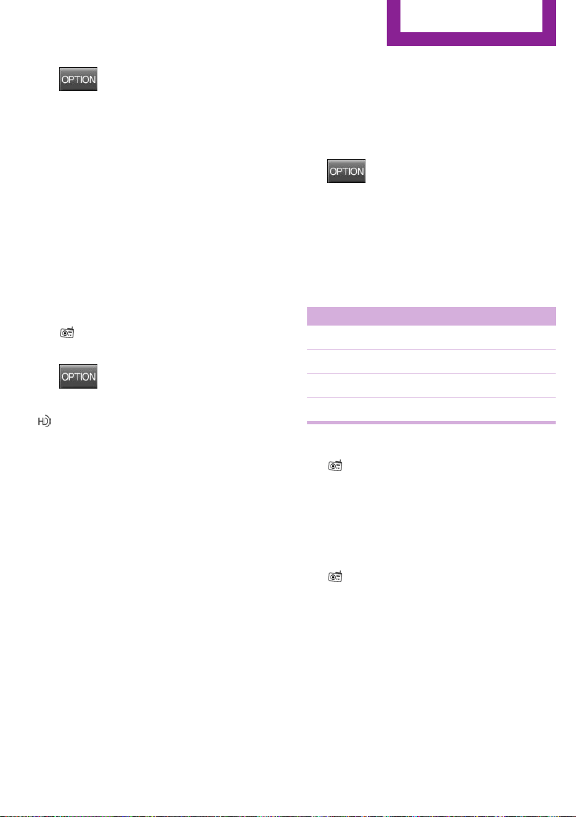
3.
Press button.
4. "RDS"
HD Radio™ reception
Many stations broadcast both analog and digi‐
tal signals.
License conditions
HD Radio technology manufactured under li‐
cense from iBiquity Digital Corporation. U. S.
and Foreign Patents. HD Radio™ and the HD,
HD Radio, and “Arc” logos are proprietary
trademarks of iBiquity Digital Corp.
Activating/deactivating digital radio
reception
1.
"Radio"
2. "FM" or "AM"
3.
Press button.
4. "HD Radio reception"
This symbol is displayed in the status line
when the audio signal is digital.
When setting a station with a digital signal, it
may take a few seconds before the station
plays in digital quality.
Information about HD Radio stations whose
station name ends with ...HD or with ...HD1:
In areas in which the station is not continuously
received in digital mode, the playback switches
between analog and digital reception. In this
case, switch off digital radio reception.
Information about HD Radio multicast stations
whose station name ends
with ...HD2, ...HD3, ...:
In areas in which the station is not continuously
received in digital mode, there may be inter‐
ruptions of the audible signal lasting several
seconds. This depends on the reception.
Displaying additional information
Some stations broadcast additional information
on the current track, such as the name of the
artist.
1. Select the desired station.
2.
Press button.
3. "Station info"
Stored stations
General information
It is possible to store up to 40 stations.
Symbol Meaning
1 ... 40 Memory location.
FM Stations out of the FM waveband.
AM Stations out of the AM waveband.
SAT Satellite radio station.
Calling up a station
1.
"Radio"
2. "Presets"
3. Select the desired memory location.
Storing a station
The station currently selected is stored.
1.
"Radio"
2. "Presets"
3. "Store station ( )"
4. Memory location to be selected.
The stations can also be stored on the Favorites
buttons, refer to page 153.
Programmable memory buttons
The first eight locations in the station list corre‐
spond to the assignment of the Favorites keys.
Seite 153
Radio
ENTERTAINMENT
153
Online Edition for Part no. 01 40 2 963 307 - VI/15

To store the station:
1. Select a station.
2. Press and hold Favorites button until a sig‐
nal sounds.
Calling up a station:
1. Press Favorites button.
Shifting stations
1. "Radio"
2. "Presets"
3. Select the station that is to be moved.
4.
Press button.
5. "Move entry"
6. Select the memory location.
Deleting a station
1.
"Radio"
2. "Presets"
3.
Press button.
4. "Delete entry"
Deleting all stations
1.
"Radio"
2. "Presets"
3.
Press button.
4. "Delete presets"
5. Confirm "Are you sure you want to delete
all saved stations?".
Satellite radio
General information
The channels are offered in predefined pack‐
ages. The packages must be subscribed by
phone.
Managing a subscription
To be able to enable or unsubscribe from the
channels, you must have reception. This is usu‐
ally the case when you have an unobstructed
view of the sky.
Enabling channels
The Unsubscribed Channels category contains
all disabled channels.
1. "Radio"
2. "Satellite radio"
3. Select the Unsubscribed category.
4. Select the channel.
5.
Press button.
6. "Manage subscription"
The phone number and an electronic serial
number, ESN, are displayed.
7. Select the displayed phone number to sub‐
scribe to the channel.
The serial number, ESN, is needed to sub‐
scribe.
You can unsubscribe from the channels again
via this phone number.
Unsubscribing from channels
1.
"Radio"
2. "Satellite radio"
3. Select the channel.
4.
Press button.
5. "Manage subscription"
The phone number and an electronic serial
number, ESN, are displayed.
6. Select the displayed phone number to un‐
subscribe from the channel.
The serial number, ESN, is needed to un‐
subscribe.
Seite 154
ENTERTAINMENT
Radio
154
Online Edition for Part no. 01 40 2 963 307 - VI/15

Selecting channels
You can only listen to enabled channels.
1. "Radio"
2. "Satellite radio"
3. Select categories.
4. Select the channel.
The selected channel is stored in the remote
control currently used.
Changing the channel
Press button.
Storing a channel
1.
"Radio"
2. "Satellite radio"
3. Select the channel.
4. Press the right button.
5. Select the memory location.
The channels are stored for the remote control
currently used.
The channels can also be stored on the pro‐
grammable memory buttons.
Weather & Traffic jump
Traffic and weather information for a selected
region is broadcast every few minutes.
Selecting a region
1.
"Radio"
2. "Satellite radio"
3.
Press button.
4. "Set area:"
5. Select region.
The region is stored in the remote control cur‐
rently used.
Activating/deactivating the jump
Reception must be guaranteed in order to acti‐
vate or deactivate.
1. "Radio"
2. "Satellite radio"
3.
Press button.
4. "Weather & Traffic Jump"
Information for the selected region is broadcast
as soon as it is available.
Information
▷ Reception may not be available in some sit‐
uations, such as under certain environmen‐
tal or topographic conditions.
▷ The signal may not be available in tunnels
or underground garages; next to tall build‐
ings; or near trees, mountains or powerful
sources of radio interference.
Seite 155
Radio
ENTERTAINMENT
155
Online Edition for Part no. 01 40 2 963 307 - VI/15
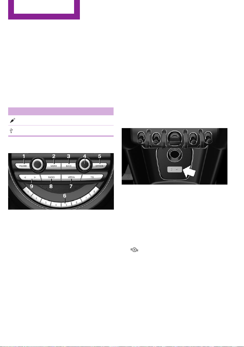
Multimedia
External devices
The concept
Various external devices can be connected to
the vehicle. Sound is played back through the
vehicle loudspeakers. The system can be oper‐
ated via the radio, depending on how the ex‐
ternal device is connected to the vehicle.
Symbol Meaning
AUX-IN port.
USB audio interface.
Overview
1 Change waveband
2 Opening the main menu
3 Menu level back
4 Selecting menu items
▷ Turn: highlight the menu item in the
display or adjust the value.
▷ Press: select the highlighted menu item
or store the setting.
5 Open the options for the respective menu
6 Programmable memory buttons
7 "Media": open the menu
8 "Radio": open the menu
9 Changing the track
AUX-IN port
Overview
For connecting audio devices, e.g., MP3 play‐
ers. Sound is played back on the vehicle loud‐
speakers.
Recommendation: use medium tone and vol‐
ume settings on the audio device. The sound
relies on the quality of the audio files.
Connecting
The AUX-In port is located at the front of the
center console.
Connect the headphones or the line-out con‐
nector of the device to the AUX-in port.
Playback
1.
Connect the audio device, switch it on and
select a track on the audio device.
2. "Media"
3. "AUX"
Volume
The volume of the sound output depends on
the audio device. If this volume differs mark‐
edly from the volume of the other audio sour‐
ces, we recommend adjusting the volume.
Seite 156
ENTERTAINMENT
Multimedia
156
Online Edition for Part no. 01 40 2 963 307 - VI/15

Adjusting the volume
1. "Media"
2. "AUX"
3. "Volume"
4. Set the desired volume.
USB audio interface
Overview
It is possible to connect external devices. Set
via radio. Sound is played back on the vehicle
loudspeakers.
Connectors for external devices
Connection via USB audio interface: Apple iPod/
iPhone, USB devices, e.g., MP3 players, USB
flash drives, or mobile phones that are sup‐
ported by the USB audio interface.
Due to the large number of audio devices avail‐
able on the market, it cannot be guaranteed
that every device/mobile phone is operable on
the vehicle.
Depending on the configuration of the audio
files, for example bit rates greater than
256 kbit/s or the number of different compres‐
sion technologies, the files may not play back
correctly in each case.
Information about compatible USB devices can
be found at www.miniusa.com/bluetooth.
Audio files
Standard audio files and playlists can be played
back.
File systems
Popular file systems for USB devices are sup‐
ported. FAT32 and exFAT are the recom‐
mended formats.
USB device connection
The USB port is located at the front of the cen‐
ter console.
Use a flexible adapter cable for connecting to
help protect the USB audio port and the USB
device from mechanical damage. The adapter
cable supplied with the USB device would be
ideal.
After the first connection
Information about the tracks and directories
stored on the USB device is transferred into the
vehicle. This may take some time, depending
on the USB device, the number of tracks and
the folder structure.
Number of tracks
Information for a maximum of 9999 tracks and
directories can be stored in the vehicle.
Copy protection
Music tracks with integrated Digital Rights Man‐
agement, DRM, cannot be played.
Playback
1.
"Media"
2. "USB device"
Playback is started.
Track search
Music tracks can be searched in three ways.
▷ Track from the current playlist.
▷ Via playlists stored in the audio device.
Seite 157
Multimedia
ENTERTAINMENT
157
Online Edition for Part no. 01 40 2 963 307 - VI/15
▷ Via the directory structure in the audio de‐
vice.
Current playback
List of tracks that is currently being played. E. g.
the list of tracks that was found in the track
search or a playlist.
1. "Media"
2. "USB device"
3. "Current playback"
4. Select the track at which the playback is to
begin.
Searching directories
1.
"Media"
2. "USB device"
3. "Browse directory"
Directories and titles at the top directory
level are displayed. Should the USB device
support external memory cards, their direc‐
tories are also displayed.
4. Select the directory.
5. Select the track at which the playback is to
begin. Tracks in subdirectories are not
played back.
Playback lists
1.
"Media"
2. "USB device"
3. "Playlists"
4. Select the playback list.
Changing the track
Press button.
A reel is made to the previous/next track from
the currently played one.
Fast forward/reverse
Press and hold this button.
The current track is fast forwarded/rewound
with increasing speed.
Playback information
Information about the current track can be dis‐
played, such as the artist and the name of the
track. This information is stored in the audio file
and does not have to match the file name of
the track.
Switching playback information on/off
1. "Media"
2. "USB device"
3.
Press button.
4. "Show playback information"
Random playback
Playback in random order can be selected for
all tracks of the USB device or for the current
play.
Switching random playback for all tracks
on/off
1.
"Media"
2. "USB device"
3.
Press button.
4. "All titles"
Switching random playback for the current
playback on/off
1.
"Media"
2. "USB device"
3.
Press button.
4. "Current playback"
Seite 158
ENTERTAINMENT
Multimedia
158
Online Edition for Part no. 01 40 2 963 307 - VI/15
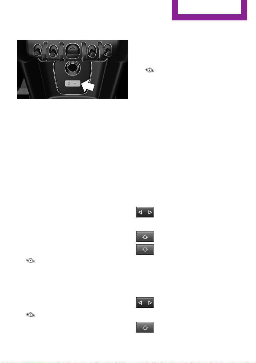
Apple iPod/iPhone port
The USB port is located at the front of the cen‐
ter console.
Use a flexible adapter cable for connecting,
e.g., the original iPod/iPhone adapter cable.
The Apple iPod/iPhone menu structure is sup‐
ported by the USB audio interface.
Track search
Music tracks can searched in various ways.
▷ Track from the current playlist.
▷ Via playlists stored in the iPod/iPhone.
▷ Via the categories saved for the music
tracks, e.g., type of music, artist, composer,
album, track.
▷ In the media audio books and podcasts.
Current playback
List of tracks that is currently being played. E. g.
the list of tracks that was found in the track
search or a playlist.
1.
"Media"
2. "USB device"
3. "Current playback"
4. Select the track at which the playback is to
begin.
Playback lists
1.
"Media"
2. "USB device"
3. "Playlists"
4. Select the playback list.
5. Select the track at which the playback is to
begin.
Categories
1. "Media"
2. "USB device"
3. Select the category.
▷ "Genres"
▷ "Artists"
▷ "Composers"
▷ "Albums"
▷ "Titles"
▷ "Audio books"
▷ "Podcasts"
4. A-Z search to reduce the list to a beginning
letter to be entered.
5. Select the track at which the playback is to
begin.
Changing the track
About the radio:
Press button.
Via the buttons on the steering wheel:
Press button.
A reel is made to the previous/next track from
the currently played one.
Fast forward/reverse
About the radio:
Press and hold this button.
Via the buttons on the steering wheel:
Seite 159
Multimedia
ENTERTAINMENT
159
Online Edition for Part no. 01 40 2 963 307 - VI/15

Press and hold this button.
The current track is fast forwarded/rewound
with increasing speed.
Random playback
The tracks of the current playback are played
back in random order.
Switching random playback on/off
1. "Media"
2. "USB device"
3.
Press button.
4. "Random"
Seite 160
ENTERTAINMENT
Multimedia
160
Online Edition for Part no. 01 40 2 963 307 - VI/15

Seite 161
Multimedia
ENTERTAINMENT
161
Online Edition for Part no. 01 40 2 963 307 - VI/15

CONNECT ME.
Online Edition for Part no. 01 40 2 963 307 - VI/15

AT A GLANCE
CONTROLS
DRIVING TIPS
ENTERTAINMENT
COMMUNICATION
MOBILITY
REFERENCE
Online Edition for Part no. 01 40 2 963 307 - VI/15

Bluetooth hands-free system
Vehicle features and op‐
tions
This chapter describes all standard, country-
specific and optional features offered with the
series. It also describes features that are not
necessarily available in your car, e. g., due to
the selected options or country versions. This
also applies to safety-related functions and sys‐
tems. The respectively applicable country provi‐
sions must be observed when using the respec‐
tive features and systems.
The concept
Mobile phones can be connected to the vehicle
via Bluetooth. After the mobile phones are
paired once, they are recognized automatically
when the ignition is switched on. As soon as
they are inside the vehicle they can be oper‐
ated via the radio and via the buttons on the
steering wheel.
Information
WARNING
Operating the integrated information sys‐
tem and communication devices while driving
can distract from traffic. It is possible to lose
control of the vehicle. There is risk of an acci‐
dent. Only use the systems or devices when the
traffic situation allows. If necessary stop and
use the systems and devices while the vehicle is
stationary.◀
Certain functions may need to be enabled by
the mobile phone provider or service provider.
At high temperatures, the charge functions of
the mobile phone can be limited under certain
circumstances, and some functions are no lon‐
ger executed.
Do not operate a mobile phone that is con‐
nected to the vehicle on the mobile phone key‐
pad, as this may lead to a malfunction.
When the mobile phone is used via the vehicle,
refer to the operating manual of the mobile
phone.
Compatible mobile
phones
Accurate information about which mobile
phones are supported with a Bluetooth inter‐
face is available at www.mini.com/connectivity.
These compatible mobile phones, with a cer‐
tain software version, support the vehicle func‐
tions described below.
Malfunctions may occur with other mobile
phones or software versions.
Displaying the vehicle identification
number and software part number
The vehicle identification number and software
part number are needed to determine which
mobile phones are supported by the mobile
phone installation package. The software ver‐
sion of the mobile phone may also be required.
1.
"Telephone"
2.
Press button.
3. "Bluetooth® info"
4. "System information"
Pairing/unpairing the
mobile phone
Requirements
▷ The mobile phone is compatible.
Seite 164
COMMUNICATION
Bluetooth hands-free system
164
Online Edition for Part no. 01 40 2 963 307 - VI/15
▷ The mobile phone is ready for operation.
▷ The ignition is switched on.
▷ Bluetooth connection on the vehicle and on
the mobile phone activated.
▷ Bluetooth presets may need to be made on
the mobile phone, e.g., for a connection
without confirmation or visibility, refer to
the mobile phone operating instructions.
▷ Set Bluetooth passkey for one-time use in
the logon procedure.
▷ Vehicle is stationary.
Bluetooth activation/deactivation
1.
"Telephone"
2.
Press button.
3. "Bluetooth®"
Pairing and connecting
WARNING
Operating the integrated information sys‐
tem and communication devices while driving
can distract from traffic. It is possible to lose
control of the vehicle. There is risk of an acci‐
dent. Only use the systems or devices when the
traffic situation allows. If necessary stop and
use the systems and devices while the vehicle is
stationary.◀
1.
"Telephone"
2. A mobile phone has not yet been paired:
"OK"
A mobile phone has been paired:
"Bluetooth®"
3. A mobile phone has not yet been paired:
the Bluetooth name of the vehicle is shown
on the display.
A mobile phone has not yet been paired:
"Add new phone". The Bluetooth name of
the vehicle is shown on the display.
4. To perform additional steps on the mobile
phone, refer to the mobile phone operating
instructions.
The Bluetooth name of the vehicle appears
on the mobile phone display. Select this.
5. Enter the same passkey on the mobile
phone and on the display
or
Compare the control number on the display
with the control number in the display of
the mobile phone and confirm.
Four mobile phones can be logged in on the
vehicle, and one mobile phone can be con‐
nected to the vehicle.
Following the initial pairing
Mobile phone is connected to the vehicle after
a brief time.
The phone book entries stored on the SIM card
or in the mobile phone are transferred to the
vehicle.
Specific settings may be necessary in some mo‐
bile phones, e.g., authorization or a secure con‐
nection; refer to the mobile phone operating
instructions.
Connecting a particular mobile phone
1.
"Telephone"
2. "Bluetooth®"
3. Select the mobile phone that is to be con‐
nected.
Unpairing the mobile phone
1.
"Telephone"
2. "Bluetooth®"
3. Highlight any mobile phone that is to be re‐
moved.
4.
Press button.
5. "Remove device" or "Remove all devices"
What to do if...
Information on compatible mobile phones, re‐
fer to page 164.
Seite 165
Bluetooth hands-free system
COMMUNICATION
165
Online Edition for Part no. 01 40 2 963 307 - VI/15

The mobile phone could not be paired or con‐
nected.
▷ Is Bluetooth activated in the vehicle and on
the mobile phone? Activate Bluetooth.
▷ Do the Bluetooth passkeys on the mobile
phone and the vehicle match? Enter the
same passkey on the mobile phone and on
the radio.
▷ Did it take longer than 30 seconds to enter
the passkey? Repeat the pairing procedure.
▷ Do the control numbers on the mobile
phone and vehicle match? Repeat the pair‐
ing procedure.
▷ Are too many Bluetooth devices connected
to the mobile phone? Delete connections to
other devices.
▷ Is the mobile phone in power-save mode or
does it have only a limited remaining bat‐
tery life? Charge the mobile phone.
The mobile phone no longer reacts?
▷ Switch the mobile phone off and on again.
▷ Ambient temperature too high or too low?
Do not subject the mobile phone to ex‐
treme ambient temperatures.
No or not all phone book entries are displayed,
or they are incomplete.
▷ Transmission of the entries is not yet com‐
plete.
▷ It is possible that only the phone book en‐
tries from the mobile phone or from the
SIM card are transmitted.
▷ It may not be possible to display phone
book entries with special characters.
▷ The number of phone book entries being
stored is too high.
The phone connection quality is poor.
▷ It may be possible to adjust the strength of
the Bluetooth signal on the mobile phone.
▷ Adjust the volume of the microphone and
loudspeakers separately.
If all points in this list have been checked and
the required function is still not available, con‐
tact the hotline, a dealer’s service center or an‐
other qualified service center or repair shop.
Controls
Adjusting the volume
During an active call, turn the left knob on the
radio until the desired volume is selected.
Automatic volume control
The automatic volume control can only be ad‐
justed during an active conversation.
1.
"Settings"
2. "Tone"
3. "Volume settings"
4. Select the desired setting: "Microphone" or
"Loudspeak."
5. Adjusting: press and turn right button.
6. Storing: press right button.
Incoming call
Receiving calls
If the number of the caller is stored in the
phone book and is transmitted by the network,
the name of the contact is displayed. Other‐
wise, only the phone number or "Unknown
caller" s displayed.
Accepting a call
About the radio
"Accept"
Via the button on the steering wheel
Press button.
Via the instrument cluster
"Accept"
Seite 166
COMMUNICATION
Bluetooth hands-free system
166
Online Edition for Part no. 01 40 2 963 307 - VI/15

Rejecting a call
About the radio
"Reject"
Via the instrument cluster
"Reject"
Ending a call
About the radio
"End call ( )"
Via the button on the steering wheel
Press button.
Via the instrument cluster
"End call"
Dialing a number
1.
"Telephone"
2. "Dial number"
3. Enter numbers using the right rotary knob.
4. Select the symbol.
Calls with multiple parties
Accepting a second call
If a second call is received during an ongoing
call, a call waiting signal sounds.
"Accept"
The second call is accepted and the current call
is put on hold.
Establishing a second call
Establish an additional call during an active call.
Dial the new phone number or select it from a
list.
▷ "Phone book"
▷ "Outgoing calls"
▷ "Received calls"
The first call is put on hold.
Switching between two calls, hold call
You can switch between two calls.
Select line with symbol in order to switch
between the conversations.
Active conversation.
Call on hold.
Establishing/ending a conference call
Two calls can be connected to a single tele‐
phone conference call.
1.
Establish two calls.
2. "Conference call"
When terminating the conference call, both
calls are ended. If one call is terminated by an‐
other party, the other call is continued if
needed.
Muting the microphone
When a call is active, the microphone can be
muted.
"Mute microphone"
The muted microphone is automatically muted:
▷ When a new connection is established.
▷ If using call-switching to switch between
call parties.
DTMF suffix dialing
DTMF suffix dialing can be used for gaining ac‐
cess to network services or for controlling devi‐
ces, e.g., to make a remote inquiry of an an‐
swering machine. The DTMF code is needed for
this purpose. The DTMF code is only available
during an active call.
1.
"Keypad dialing"
2. Enter DTMF code.
Seite 167
Bluetooth hands-free system
COMMUNICATION
167
Online Edition for Part no. 01 40 2 963 307 - VI/15
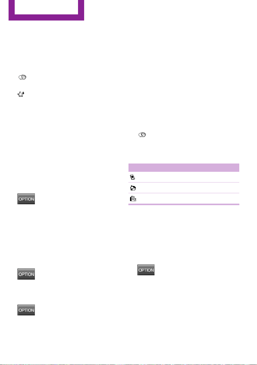
Favorites
Up to 12 phone numbers can be stored in the
Favorites. Only the occupied places of the Fa‐
vorites list are displayed.
Storing Favorites
1. "Telephone"
2. "Favorites"
3. "Add favorite"
4. Select the list from which the entry is to be
added:
▷ "Phone book"
▷ "Outgoing calls"
▷ "Received calls"
5. Select entry from list and desired phone
number.
6. Insert and select the cursor at the desired
place in the Favorites.
Move favorite
1.
Highlight the desired favorite.
2.
Press button and "Move favorite".
or
Press the right button, and select the phone
number.
3. Insert and select the cursor at the desired
place in the Favorites.
Remove from Favorites
1.
Highlight the desired favorite.
2.
Press button.
3. "Remove from favorites"
Deleting Favorites
1. Press button.
2. "Delete favorites"
3. "OK"
Phone book
General information
The telephone accesses the contacts stored in
the mobile phone. All contacts for which a tele‐
phone number is entered are displayed. Maxi‐
mally 4 phone numbers per contact can be dis‐
played.
Displaying
Phone book entries are automatically transmit‐
ted from the mobile phone to the vehicle, de‐
pending on the mobile phone. Fig. 4 Entries in
the phone book: "Keyword search"
1.
"Telephone"
2. "Phone book"
The symbols show how the entries are stored
on the mobile phone.
Symbol Meaning
Mobile phone number.
Home phone number.
Business phone number.
Selecting the sorting order of the
names
The phone book entries can be displayed in dif‐
ferent sequences. Depending on how the con‐
tacts are stored in the mobile phone, the sort‐
ing order of the names may differ from the
selected sorting order.
1. Press button.
2. "Display:""Last/First name" or "First/Last
name"
3. "First name Last name" or "Last name, First
name"
Calling
1.
Select contact.
2. Select the desired phone number.
Seite 168
COMMUNICATION
Bluetooth hands-free system
168
Online Edition for Part no. 01 40 2 963 307 - VI/15

Add phone numbers to Favorites
1. Mark the entry from the list.
2.
Press button and "Add to
favorites".
or
Press the right button, and select the phone
number.
3. Select the desired phone number as
needed.
4. Insert and select the cursor at the desired
place in the Favorites.
Redialing
The list of the last 20 numbers of the mobile
phone selected are displayed.
1.
"Telephone"
2. "Redial"
Add phone numbers to Favorites
1.
Mark the entry from the list.
2.
Press button and "Add to
favorites".
or
Press the right button, and select the phone
number.
3. Select the desired phone number as
needed.
4. Insert and select the cursor at the desired
place in the Favorites.
Dialing the number via the instrument
cluster
This is possible when there is no active call.
1. Press button on the steering wheel.
The last numbers selected are displayed in
the instrument cluster.
2. If necessary, select another number.
3.
Press the key again to establish the
connection.
Received calls
The list of the 20 last received or missed calls of
the cell phone are displayed.
1. "Telephone"
2. "Received calls"
Add phone numbers to Favorites
1. Mark the entry from the list.
2.
Press button and "Add to
favorites".
or
Press the right button, and select the phone
number.
3. Select the desired phone number as
needed.
4. Insert and select the cursor at the desired
place in the Favorites.
Hands-free system
General information
Calls that are being made on the hands-free
system can be continued on the mobile phone
and vice versa.
From the mobile phone to the hands-
free system
Calls that were begun outside of the Bluetooth
range of the vehicle can be continued on the
hands-free system with the ignition switched
on.
Depending on the mobile phone, the system
automatically switches to the hands-free sys‐
tem.
If the system does not switch over automati‐
cally, follow the instructions on the mobile
phone display; refer also to the mobile phone
operating instructions.
Seite 169
Bluetooth hands-free system
COMMUNICATION
169
Online Edition for Part no. 01 40 2 963 307 - VI/15

From the hands-free system to the
mobile phone
Calls that are made on the hands-free system
can in some cases be continued on the mobile
phone; this depends on the mobile phone.
Follow the instructions on the mobile phone
display; refer also to the mobile phone operat‐
ing instructions.
Seite 170
COMMUNICATION
Bluetooth hands-free system
170
Online Edition for Part no. 01 40 2 963 307 - VI/15

Seite 171
Bluetooth hands-free system
COMMUNICATION
171
Online Edition for Part no. 01 40 2 963 307 - VI/15
MOVE ME.
Online Edition for Part no. 01 40 2 963 307 - VI/15

AT A GLANCE
CONTROLS
DRIVING TIPS
ENTERTAINMENT
COMMUNICATION
MOBILITY
REFERENCE
Online Edition for Part no. 01 40 2 963 307 - VI/15
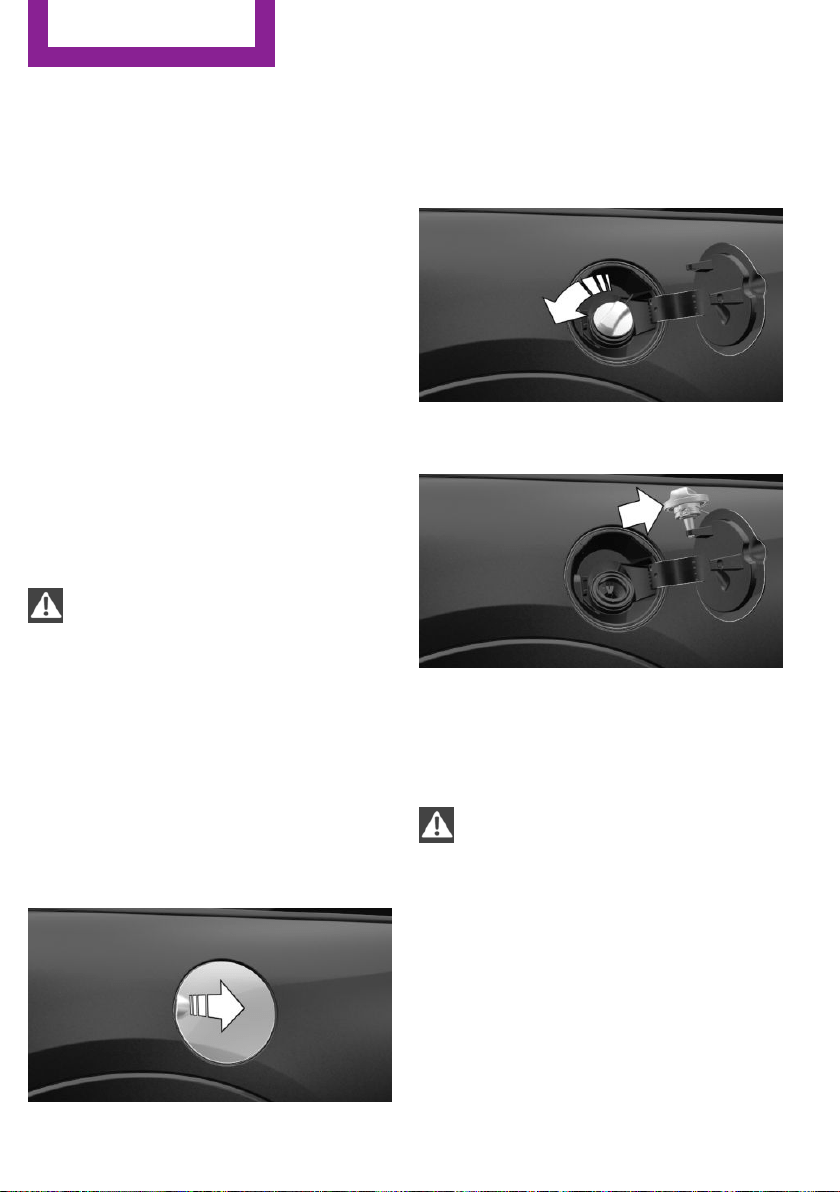
Refueling
Vehicle features and op‐
tions
This chapter describes all standard, country-
specific and optional features offered with the
series. It also describes features that are not
necessarily available in your car, e. g., due to
the selected options or country versions. This
also applies to safety-related functions and sys‐
tems. The respectively applicable country provi‐
sions must be observed when using the respec‐
tive features and systems.
Information
Observe the fuel recommendation, refer to
page 176, prior to refueling.
CAUTION
With a range of less than 30 miles/50 km
it is possible that the engine will no longer have
sufficient fuel. Engine functions are no longer
ensured. There is risk of property damage. Re‐
fuel promptly.◀
Fuel lid
Opening
1.
Grasp the fuel filler flap at the rear edge
and open it.
2. Turn the tank lid counterclockwise.
3. Place the tank lid in the bracket attached to
the fuel filler flap.
Closing
1.
Fit the lid and turn it clockwise until you
clearly hear a click.
2. Close the fuel filler flap.
WARNING
The retaining strap of the fuel cap be
jammed and crushed during closing. In this
case, the lid cannot be correctly closed and fuel
vapors or fuel can escape. There is risk of inju‐
ries or risk of property damage. Pay attention
that the retaining strap is not jammed or
crushed when closing the lid.◀
Manually unlocking fuel filler flap
E. g. in the event of an electrical malfunction.
The release is located in the trunk.
Seite 174
MOBILITY
Refueling
174
Online Edition for Part no. 01 40 2 963 307 - VI/15

Remove the cover.
Pull the green knob with the fuel pump symbol.
This releases the fuel filler flap.
Observe the following
when refueling
CAUTION
Fuels are toxic and aggressive. Overfilling
of the fuel tank can damage the fuel system.
On contact with painted surfaces, damage may
occur to these surfaces. The environment is
polluted. There is risk of property damage.
Avoid overfilling.◀
The fuel tank is full when the filler nozzle clicks
off the first time.
Observe safety regulations posted at the gas
station.
Seite 175
Refueling
MOBILITY
175
Online Edition for Part no. 01 40 2 963 307 - VI/15

Fuel
Vehicle features and op‐
tions
This chapter describes all standard, country-
specific and optional features offered with the
series. It also describes features that are not
necessarily available in your car, e. g., due to
the selected options or country versions. This
also applies to safety-related functions and sys‐
tems. The respectively applicable country provi‐
sions must be observed when using the respec‐
tive features and systems.
Fuel recommendation
General information
Depending on the region, many gas stations
sell fuel that has been customized to winter or
summer conditions. Fuel that is available in
winter helps make a cold start easier, e.g.
Information
CAUTION
Even fuels that conform to the specifica‐
tions can be of low quality. This may cause en‐
gine problems, for instance poor engine start-
up behavior, poor handling and/or poor
performance. There is risk of property damage.
In case of engine problems, switch gas stations
or use a brand name fuel with a higher octane
rating.◀
Gasoline
For the best fuel efficiency, the gasoline should
be sulfur-free or very low in sulfur content.
Fuels that are marked on the gas pump as con‐
taining metal must not be used.
CAUTION
Even small amounts of wrong fuel or
wrong fuel additives can damage the fuel sys‐
tem and the engine. Furthermore, the catalytic
converter is permanently damaged. There is
risk of property damage. Do not refuel or add
the following in the case of gasoline engines:
▷ Leaded gasoline.
▷ Metallic additives, e.g. manganese or iron.
Do not press the Start/Stop button after refuel‐
ing the wrong fuel. Contact a dealer’s service
center or another qualified service center or re‐
pair shop.◀
Fuels with a maximum ethanol content of
25 %, i. e. E10 or E25, may be used for refuel‐
ing.
Ethanol should satisfy the following quality
standards:
US: ASTM 4806–xx
CAN: CGSB-3.511–xx
xx: comply with the current standard in each
case.
CAUTION
Wrong fuels can damage the fuel system
and the engine. There is risk of property dam‐
age. Do not use a fuel with a higher ethanol
percentage than recommended or one with
other types of alcohol, e.g. M5 to M100.◀
Recommended fuel grade
MINI recommends AKI 91.
John Cooper Works:
MINI recommends AKI 93.
Minimum fuel grade
MINI recommends AKI 89.
Seite 176
MOBILITY
Fuel
176
Online Edition for Part no. 01 40 2 963 307 - VI/15

CAUTION
Fuel that does not comply with the mini‐
mum quality can compromise engine function
or cause engine damage. There is risk of prop‐
erty damage. Do not fill with fuel that does not
comply with the minimum quality.◀
If you use gasoline with this minimum AKI Rat‐
ing, the engine may produce knocking sounds
when starting at high outside temperatures.
This has no effect on the engine life.
CAUTION
The use of poor-quality fuels may result in
harmful engine deposits or damage. Addition‐
ally, problems relating to drivability, starting
and stalling, especially under certain environ‐
mental conditions such as high ambient tem‐
perature and high altitude, may occur.
If drivability problems are encountered, we rec‐
ommend switching to a high quality gasoline
brand and a higher octane grade — AKI num‐
ber — for a few tank fills. To avoid harmful en‐
gine deposits, it is highly recommended to pur‐
chase gasoline from Top Tier retailers.
Failure to comply with these recommendations
may result in the need for unscheduled mainte‐
nance.◀
Seite 177
Fuel
MOBILITY
177
Online Edition for Part no. 01 40 2 963 307 - VI/15
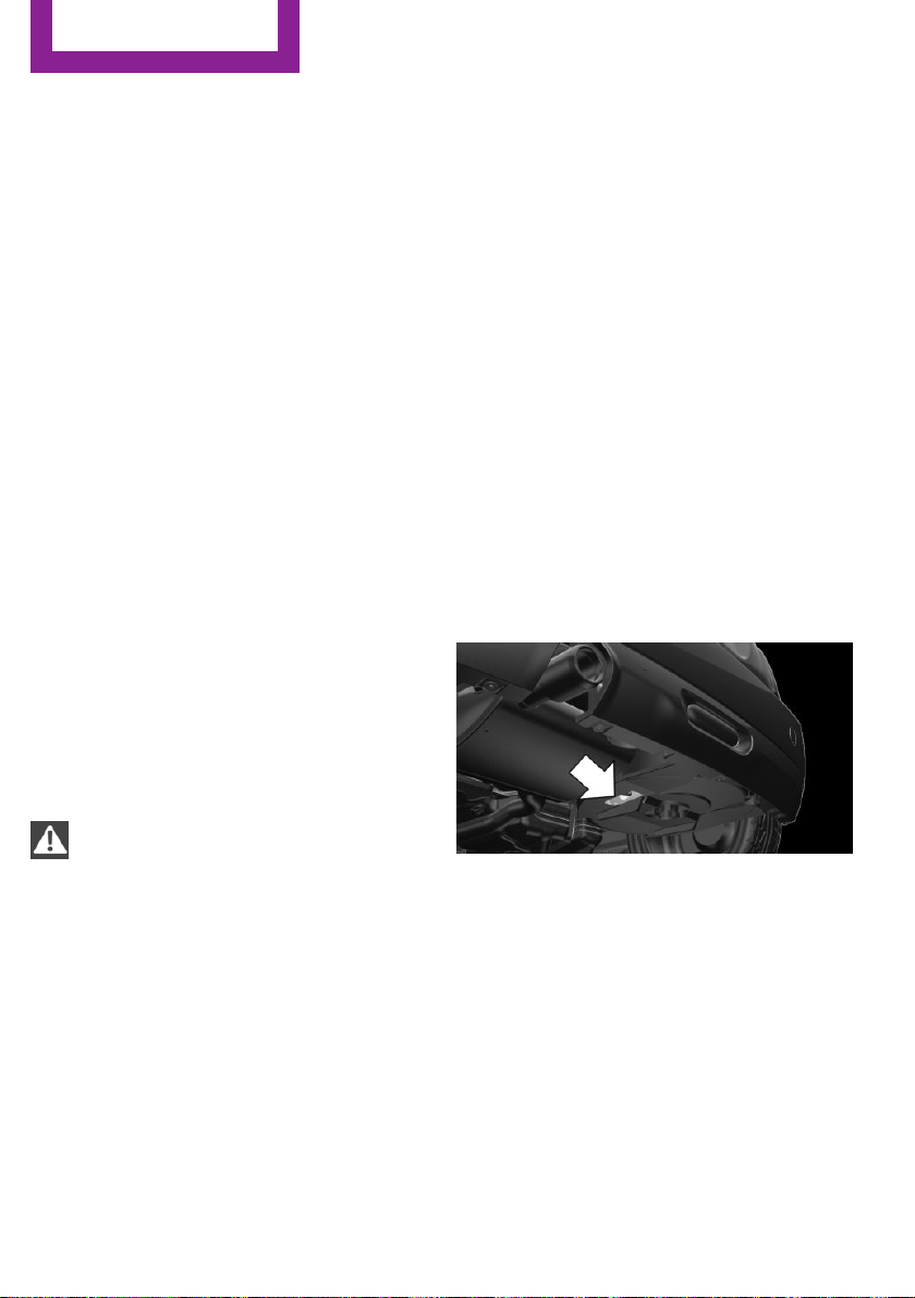
Wheels and tires
Vehicle features and op‐
tions
This chapter describes all standard, country-
specific and optional features offered with the
series. It also describes features that are not
necessarily available in your car, e. g., due to
the selected options or country versions. This
also applies to safety-related functions and sys‐
tems. The respectively applicable country provi‐
sions must be observed when using the respec‐
tive features and systems.
Tire inflation pressure
Safety information
The tire characteristics and tire inflation pres‐
sure influence the following:
▷ The service life of the tires.
▷ Road safety.
▷ Driving comfort.
Checking the tire inflation pressure
WARNING
A tire with low or missing tire inflation
pressure impacts handling, such as steering
and braking response. There is risk of an acci‐
dent. Regularly check the tire inflation pressure,
and correct it as needed, e.g. twice a month
and before a long trip.◀
Tires have a natural, consistent loss of tire infla‐
tion pressure.
Tires heat up while driving, and the tire inflation
pressure increases along with the tire's temper‐
ature. The tire inflation pressure specifications
relate to cold tires or tires with the ambient
temperature.
Only check the tire inflation pressure when the
tires are cold. This means after driving no more
than 1.25 miles/2 km or when the vehicle has
been parked for at least 2 hours.
The displays of inflation devices may under-
read by up to 0.1 bar.
For Flat Tire Monitor: after correcting the tire
inflation pressure, reinitialize the Flat Tire Moni‐
tor.
For Tire Pressure Monitor: after correcting the
tire inflation pressure, reset the Tire Pressure
Monitor.
▷ Reinitialize the Flat Tire Monitor.
▷ Reinitialize the Tire Pressure Monitor.
Checking the inflation pressure of the
emergency wheel
Located behind the bumper on the underside
of the vehicle is an opening for checking the
tire inflation pressure.
Pressure specifications
The tire inflation pressure table, refer to
page 179, contains all tire inflation pressure
specifications for the specified tire sizes at the
ambient temperature. The tire inflation pres‐
sure values apply to tire sizes approved by the
manufacturer of the vehicle for the vehicle
type.
To identify the correct tire inflation pressure,
please note the following:
Seite 178
MOBILITY
Wheels and tires
178
Online Edition for Part no. 01 40 2 963 307 - VI/15
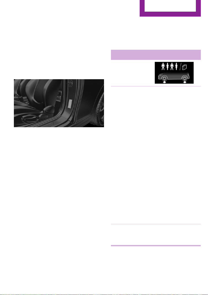
▷ Tire sizes of your vehicle.
▷ Maximum permitted driving speed.
Tire inflation pressures up to 100 mph/
160 km/h
For speeds of up to 100 mph/160 km/h and for
optimum driving comfort, note the pressure
values in the tire inflation pressure table, refer
to page 179, and adjust as necessary.
These pressure values can also be found on the
tire inflation pressure label on the driver's door
pillar.
Do not exceed a speed of 100 mph/160 km/h.
Tire inflation pressure values up to
100 mph/160 km/h
On 3-door models: COOPER
Tire size Pressure specifications in
bar/PSI
Specifications in
bar/PSI with cold
tires
175/60 R 16 86 H M
+S XL RSC
175/65 R 15 84 H M
+S A/S Std
175/65 R 15 84 H M
+S Std
175/65 R 15 84 H
Std
195/55 R 16 87 H M
+S RSC
195/55 R 16 87 V M
+S A/S RSC
195/55 R 16 87 W
RSC
205/45 R 17 88 V M
+S XL A/S RSC
205/45 R 17 88 V M
+S XL RSC
205/45 R 17 88 W XL
RSC
205/40 R 18 86 W XL
RSC
2.4 / 35 2.4 / 35
Emergency wheel
T 115/70 R 15 90 M
Speed up to a max. of
50 mph / 80 km/h
4.2 / 60
Seite 179
Wheels and tires
MOBILITY
179
Online Edition for Part no. 01 40 2 963 307 - VI/15
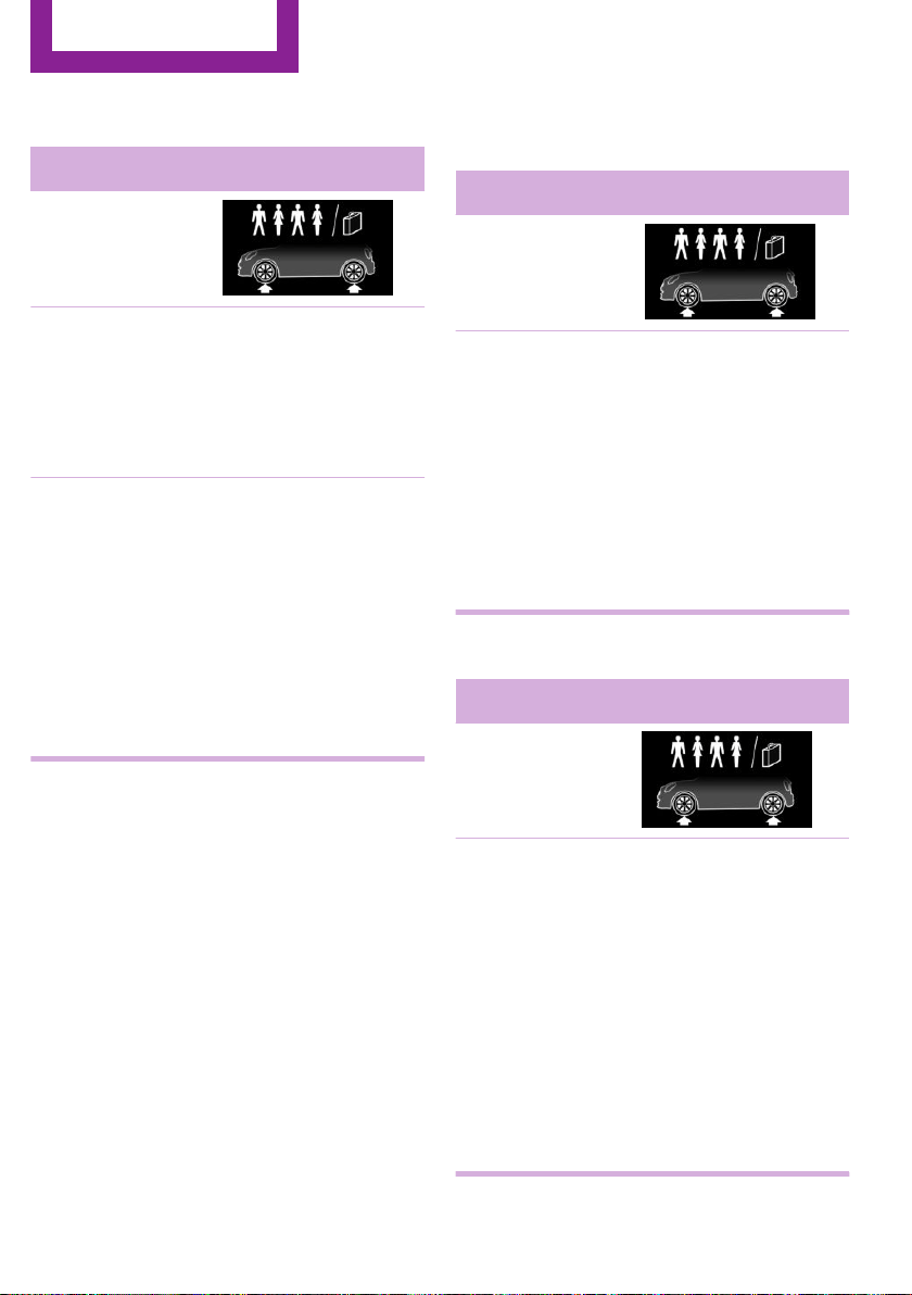
On 3-door models: COOPER S
Tire size Pressure specifications in
bar/PSI
Specifications in
bar/PSI with cold
tires
195/55 R 16 87 H M
+S RSC
195/55 R 16 87 V M
+S A/S RSC
195/55 R 16 87 W
RSC
2.4 / 35 2.4 / 35
175/60 R 16 86 H M
+S XL RSC
205/45 R 17 88 V M
+S XL A/S RSC
205/45 R 17 88 V M
+S XL RSC
205/45 R 17 88 W XL
RSC
205/40 R 18 86 W XL
RSC
2.6 / 38 2.4 / 35
On 3-door models: JOHN COOPER
WORKS
Tire size Pressure specifications in
bar/PSI
Specifications in
bar/PSI with cold
tires
185/50 R 17 86 H M
+S XL RSC
205/45 R 17 88 W
XL RSC
205/45 R 17 88 V M
+S XL A/S RSC
205/45 R 17 88 V M
+S XL RSC
205/40 R 18 86 W
XL RSC
2.9 /42 2.7 / 39
On 5-door models: COOPER
Tire size Pressure specifications in
bar/PSI
Specifications in
bar/PSI with cold
tires
175/65 R 15 84 H M
+S A/S Std
175/65 R 15 84 H M
+S Std
175/65 R 15 84 H
Std
195/55 R 16 87 H M
+S RSC
195/55 R 16 87 V M
+S A/S RSC
195/55 R 16 87 W
RSC
2.5 / 36 2.3 / 33
Seite 180
MOBILITY
Wheels and tires
180
Online Edition for Part no. 01 40 2 963 307 - VI/15

Tire size Pressure specifications in
bar/PSI
205/45 R 17 88 V M
+S XL A/S RSC
205/45 R 17 88 V M
+S XL RSC
205/45 R 17 88 W
XL RSC
2.5 / 36 2.4 / 35
175/60 R 16 86 H M
+S XL RSC
205/40 R 18 86 W
XL RSC
2.6 / 38 2.6 / 38
Emergency wheel
T 115/70 R 15 90 M
Speed up to a max. of
50 mph / 80 km/h
4.2 / 60
On 5-door models: COOPER S
Tire size Pressure specifications in
bar/PSI
Specifications in
bar/PSI with cold
tires
195/55 R 16 87 H M
+S RSC
195/55 R 16 87 V M
+S A/S RSC
195/55 R 16 87 W
RSC
2.5 / 36 2.3 / 33
175/60 R 16 86 H M
+S XL RSC
205/45 R 17 88 V M
+S XL A/S RSC
205/45 R 17 88 V M
+S XL RSC
205/45 R 17 88 W XL
RSC
205/40 R 18 86 W XL
RSC
2.7 / 39 2.7 / 39
Tire inflation pressures at max. speeds
above 100 mph/160 km/h
WARNING
In order to drive at maximum speeds in
excess of 100 mph/160 km/h, please observe,
and, if necessary, adjust tire pressures for
speeds exceeding 100 mph/160 km/h from the
relevant table on the following pages. Other‐
wise tire damage and accidents could occur.◀
Seite 181
Wheels and tires
MOBILITY
181
Online Edition for Part no. 01 40 2 963 307 - VI/15

Tire inflation pressure values over
100 mph/160 km/h
On 3-door models: COOPER
Tire size Pressure specifications in
bar/PSI
Specifications in
bar/PSI with cold
tires
175/65 R 15 84 H M
+S A/S Std
175/65 R 15 84 H M
+S Std
175/65 R 15 84 H
Std
175/60 R 16 86 H M
+S XL RSC
195/55 R 16 87 H M
+S RSC
195/55 R 16 87 V M
+S A/S RSC
195/55 R 16 87 W
RSC
205/45 R 17 88 V M
+S XL A/S RSC
205/45 R 17 88 V M
+S XL RSC
205/45 R 17 88 W XL
RSC
205/40 R 18 86 W XL
RSC
2.8 / 41 2.6 / 38
Compact wheel
T 115/70 R 15 90 M
Speed up to a max. of
50 mph / 80 km/h
4.2 / 60
On 3-door models: COOPER S
Tire size Pressure specifications in
bar/PSI
Specifications in
bar/PSI with cold
tires
195/55 R 16 87 H M
+S RSC
195/55 R 16 87 V M
+S A/S RSC
195/55 R 16 87 W
RSC
2.8 / 41 2.6 / 38
175/60 R 16 86 H M
+S XL RSC
205/45 R 17 88 V M
+S XL A/S RSC
205/45 R 17 88 V M
+S XL RSC
205/45 R 17 88 W XL
RSC
205/40 R 18 86 W XL
RSC
3.1 / 45 2.9 /42
Seite 182
MOBILITY
Wheels and tires
182
Online Edition for Part no. 01 40 2 963 307 - VI/15

On 3-door models: JOHN COOPER
WORKS
Tire size Pressure specifications in
bar/PSI
Specifications in
bar/PSI with cold
tires
185/50 R 17 86 H
M+S XL RSC
205/45 R 17 88 W
XL RSC
205/45 R 17 88 V M
+S XL A/S RSC
205/45 R 17 88 V M
+S XL RSC
3.1 / 45 2.9 /42
205/40 R 18 86 W
XL RSC
3.4 / 49 3.2 / 46
On 5-door models: COOPER
Tire size Pressure specifications in
bar/PSI
Specifications in
bar/PSI with cold
tires
175/65 R 15 84 H M
+S A/S Std
175/65 R 15 84 H M
+S Std
175/65 R 15 84 H
Std
195/55 R 16 87 H M
+S RSC
195/55 R 16 87 V M
+S A/S RSC
195/55 R 16 87 W
RSC
205/45 R 17 88 V M
+S XL A/S RSC
205/45 R 17 88 V M
+S XL RSC
205/45 R 17 88 W
XL RSC
2.8 / 41 2.6 / 38
175/60 R 16 86 H M
+S XL RSC
205/40 R 18 86 W
XL RSC
2.8 / 41 2.8 / 41
Compact wheel
T 115/70 R 15 90 M
Speed up to a max. of
50 mph / 80 km/h
4.2 / 60
Seite 183
Wheels and tires
MOBILITY
183
Online Edition for Part no. 01 40 2 963 307 - VI/15

On 5-door models: COOPER S
Tire size Pressure specifications in
bar/PSI
Specifications in
bar/PSI with cold
tires
195/55 R 16 87 H M
+S RSC
195/55 R 16 87 V M
+S A/S RSC
195/55 R 16 87 W
RSC
2.8 / 41 2.8 / 41
175/60 R 16 86 H M
+S XL RSC
205/45 R 17 88 V M
+S XL A/S RSC
205/45 R 17 88 V M
+S XL RSC
205/45 R 17 88 W XL
RSC
205/40 R 18 86 W XL
RSC
3.1 / 45 3.1 / 45
Tire identification marks
Tire size
205/45 R 17 84 V
205: nominal width in mm
45: aspect ratio in %
R: radial tire code
17: rim diameter in inches
84: load rating, not for ZR tires
F: speed rating, before the R on ZR tires
Speed letter
T = up to 118 mph, 190 km/h
H = up to 131 mph, 210 km/h
V = up to 150 mph, 240 km/h
W = up to 167 mph, 270 km/h
Y = up to 186 mph, 300 km/h
Tire Identification Number
DOT code: DOT xxxx xxx 0115
xxxx: manufacturer code for the tire brand
xxx: tire size and tire design
0115: tire age
Tires with DOT codes meet the guidelines of
the U.S. Department of Transportation.
Tire age
DOT … 0115: the tire was manufactured in the
1st week of 2015.
Recommendation
Regardless of wear and tear, replace tires at
least every 6 years.
Uniform Tire Quality Grading
Quality grades can be found where applicable
on the tire sidewall between tread shoulder
and maximum section width.
For example: Treadwear 200; Traction AA;
Temperature A
DOT Quality Grades
Treadwear
Traction AA A B C
Temperature A B C
All passenger car tires must conform to Federal
Safety Requirements in addition to these
grades.
Treadwear
The treadwear grade is a comparative rating
based on the wear rate of the tire when tested
under controlled conditions on a specified gov‐
ernment test course. For example, a tire graded
150 would wear one and one-half, 1 g, times as
well on the government course as a tire graded
Seite 184
MOBILITY
Wheels and tires
184
Online Edition for Part no. 01 40 2 963 307 - VI/15
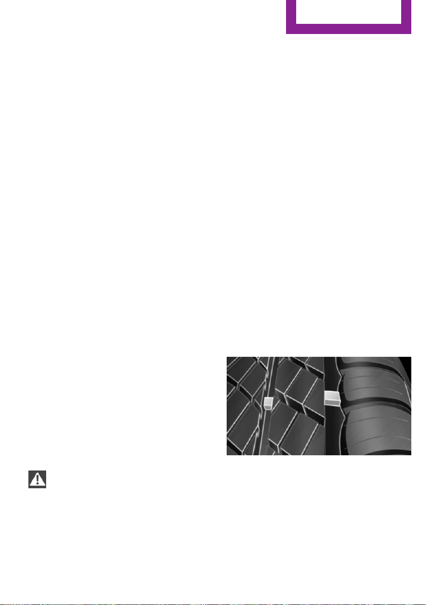
100. The relative performance of tires depends
upon the actual conditions of their use, how‐
ever, and may depart significantly from the
norm due to variations in driving habits, service
practices and differences in road characteristics
and climate.
Traction
The traction grades, from highest to lowest, are
AA, A, B, and C.
Those grades represent the tire's ability to stop
on wet pavement as measured under control‐
led conditions on specified government test
surfaces of asphalt and concrete. A tire marked
C may have poor traction performance.
The traction grade assigned to this tire is based
on straight-ahead braking traction tests, and
does not include acceleration, cornering, hy‐
droplaning, or peak traction characteristics.
Temperature
The temperature grades are A, the highest, B,
and C, representing the tire's resistance to the
generation of heat and its ability to dissipate
heat when tested under controlled conditions
on a specified indoor laboratory test wheel.
Sustained high temperature can cause the ma‐
terial of the tire to degenerate and reduce tire
life, and excessive temperature can lead to
sudden tire failure. The grade C corresponds to
a level of performance which all passenger car
tires must meet under the Federal Motor Vehi‐
cle Safety Standard No. 109. Grades Band A
represent higher levels of performance on the
laboratory test wheel than the minimum re‐
quired by law.
WARNING
The temperature grade for this tire is es‐
tablished for a tire that is properly inflated and
not overloaded. Excessive speed, underinfla‐
tion, or excessive loading, either separately or
in combination, can cause heat buildup and
possible tire failure.◀
RSC – Run-flat tires
Run-flat tires, refer to page 187, are labeled
with a circular symbol containing the letters
RSC marked on the sidewall.
M+S
Winter and all-season tires with better cold
weather performance than summer tires.
Tire tread
Summer tires
Do not drive with a tire tread depth of less than
0.12 in/3 mm.
There is an increased danger of hydroplaning if
the tread depth is less than 0.12 in/3 mm.
Winter tires
Do not drive with a tire tread depth of less than
0.16 in/4 mm.
Below a tread depth of 0.16 in/4 mm, tires are
less suitable for winter operation.
Minimum tread depth
Wear indicators are distributed around the tire's
circumference and have the legally required
minimum height of 0.063 in/1.6 mm.
They are marked on the side of the tire with
TWI, Tread Wear Indicator.
Seite 185
Wheels and tires
MOBILITY
185
Online Edition for Part no. 01 40 2 963 307 - VI/15
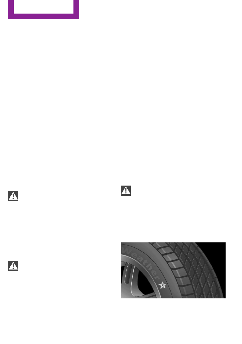
Tire damage
General information
Inspect your tires often for damage, foreign ob‐
jects lodged in the tread, and tread wear.
Information
Driving over rough or damaged road surfaces,
as well as debris, curbs and other obstacles can
cause serious damage to wheels, tires and sus‐
pension parts. This is more likely to occur with
low-profile tires, which provide less cushioning
between the wheel and the road. Be careful to
avoid road hazards and reduce your speed, es‐
pecially if your vehicle is equipped with low-
profile tires.
Indications of tire damage or other vehicle mal‐
functions:
▷ Unusual vibrations while driving.
▷ Unusual handling such as a strong ten‐
dency to pull to the left or right.
Damage can, e. g., be caused by driving over
curbs, road damage, or similar things.
WARNING
Damaged tires can lose tire inflation pres‐
sure, which can lead to loss of vehicle control.
There is risk of an accident. If tire damage is
suspected while driving, immediately reduce
speed and stop. Have wheels and tires
checked. For this purpose, drive carefully to the
nearest dealer’s service center or another
qualified service center or repair shop. Have
vehicle towed or transported as needed.◀
WARNING
Damaged tires can lose tire inflation pres‐
sure, which can lead to loss of vehicle control.
There is risk of an accident. Do not repair dam‐
aged tires, but have them replaced.◀
Changing wheels and
tires
Mounting
Have mounting and wheel balancing carried
out by a dealer’s service center or another
qualified service center or repair shop.
Wheel and tire combination
You can ask the dealer’s service center or an‐
other qualified service center or repair shop
about the right wheel/tire combination and
wheel rim versions for the vehicle.
Incorrect wheel and tire combinations impair
the function of a variety of systems such as ABS
or DSC.
To maintain good handling and vehicle re‐
sponse, use only tires with a single tread con‐
figuration from a single manufacturer.
Following tire damage, have the original wheel
and tire combination remounted on the vehicle
as soon as possible.
WARNING
Wheels and tires which are not suitable
for your vehicle can damage parts of the vehi‐
cle, e. g. due to contact with the body due to
tolerances despite the same official size rating.
There is risk of an accident.◀
Recommended tire brands
For each tire size, the manufacturer of your ve‐
hicle recommends certain tire brands. These
can be identified by a star on the tire sidewall.
Seite 186
MOBILITY
Wheels and tires
186
Online Edition for Part no. 01 40 2 963 307 - VI/15
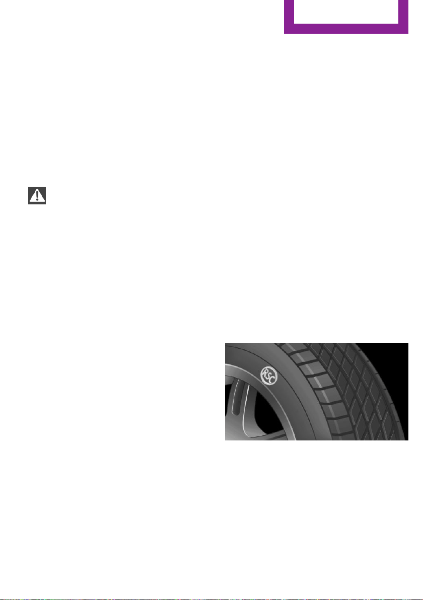
New tires
Tire traction is not optimal due to manufactur‐
ing circumstances when tires are brand-new;
they achieve their full traction potential after a
break-in time.
Drive conservatively for the first
200 miles/300 km.
Retreaded tires
The manufacturer of your vehicle does not rec‐
ommend the use of retreaded tires.
WARNING
Retreated tires can have different tire
casing structures. With advanced age the serv‐
ice life can be limited. There is risk of an acci‐
dent. Do not use retreated tires.◀
Winter tires
Winter tires are recommended for operating on
winter roads.
Although so-called all-season M+S tires provide
better winter traction than summer tires, they
do not provide the same level of performance
as winter tires.
Maximum speed of winter tires
If the maximum speed of the vehicle is higher
than the permissible speed for the winter tires,
then a respective symbol is displayed in your
field of vision. The plate is available from a
dealer’s service center or another qualified
service center or repair shop.
With mounted winter tires, observe and adhere
to the permissible maximum speed.
Run-flat tires
If you are already using run-flat tires, for your
own safety you should replace them only with
the same kind. No spare tire is available in the
case of a flat tire. A dealer’s service center or
another qualified service center or repair shop
will be glad to answer additional questions at
any time.
Rotating wheels between axles
Different wear patterns can occur on the front
and rear axles depending on individual driving
conditions.
The tires can be rotated between the axles to
achieve even wear. A dealer’s service center or
another qualified service center or repair shop
will be glad to answer additional questions at
any time.
After rotating, check the tire pressure and cor‐
rect if needed.
Storage
Store wheels and tires in a cool, dry place with
as little exposure to light as possible.
Always protect tires against all contact with oil,
grease and fuels.
Do not exceed the maximum tire inflation pres‐
sure indicated on the side wall of the tire.
Run-flat tires
Label
RSC label on the tire sidewall.
The wheels are composed of tires that are self-
supporting to a limited degree.
The support of the sidewall allows the tire to re‐
main drivable to a restricted degree in the
event of a tire inflation pressure loss.
Continued driving with a damaged tire, refer to
page 89.
Seite 187
Wheels and tires
MOBILITY
187
Online Edition for Part no. 01 40 2 963 307 - VI/15

Continued driving with a damaged tire, refer to
page 86.
Changing run-flat tires
For your own safety, only use run-flat tires. No
spare tire is available in the case of a flat tire. A
dealer’s service center or another qualified
service center or repair shop will be glad to an‐
swer additional questions at any time.
Repairing a flat tire
Safety measures
▷ Park the vehicle as far away as possible
from passing traffic and on solid ground.
▷ Switch on the hazard warning system.
▷ Secure the vehicle against rolling away by
setting the parking brake.
▷ Turn the steering wheel until the front
wheels are in the straight-ahead position
and engage the steering wheel lock.
▷ Have all vehicle occupants get out of the
vehicle and ensure that they remain out‐
side the immediate area in a safe place,
such as behind a guardrail.
▷ If necessary, set up a warning triangle at an
appropriate distance.
Mobility System
The concept
With the Mobility System, minor tire damage
can be sealed quickly to enable continued
travel. To accomplish this, sealant is pumped
into the tires, which seals the damage from the
inside.
The compressor can be used to check the tire
inflation pressure.
Information
▷ Follow the instructions on using the Mobi‐
lity System found on the compressor and
sealant container.
▷ Use of the Mobility System may be ineffec‐
tive if the tire puncture measures approx.
1/8 in/4 mm or more.
▷ Contact a dealer’s service center or another
qualified service center or repair shop if the
tire cannot be made drivable.
▷ If possible, do not remove foreign bodies
that have penetrated the tire.
▷ Pull the speed limit sticker off the sealant
container and apply it to the steering
wheel.
▷ The use of a sealant can damage the TPM
wheel electronics. In this case, have the
electronics checked at the next opportunity
and have them replaced if needed.
DANGER
If the exhaust pipe is blocked or ventila‐
tion is insufficient, harmful exhaust gases can
enter into the vehicle. The exhaust gases con‐
tain carbon monoxide, an odorless and color‐
less but highly toxic gas. In enclosed areas, ex‐
haust gases can also accumulate outside of the
vehicle. There is danger to life. Keep the ex‐
haust pipe free and ensure sufficient ventila‐
tion.◀
Storage
The Mobility System is located under the cargo
floor panel.
Seite 188
MOBILITY
Wheels and tires
188
Online Edition for Part no. 01 40 2 963 307 - VI/15
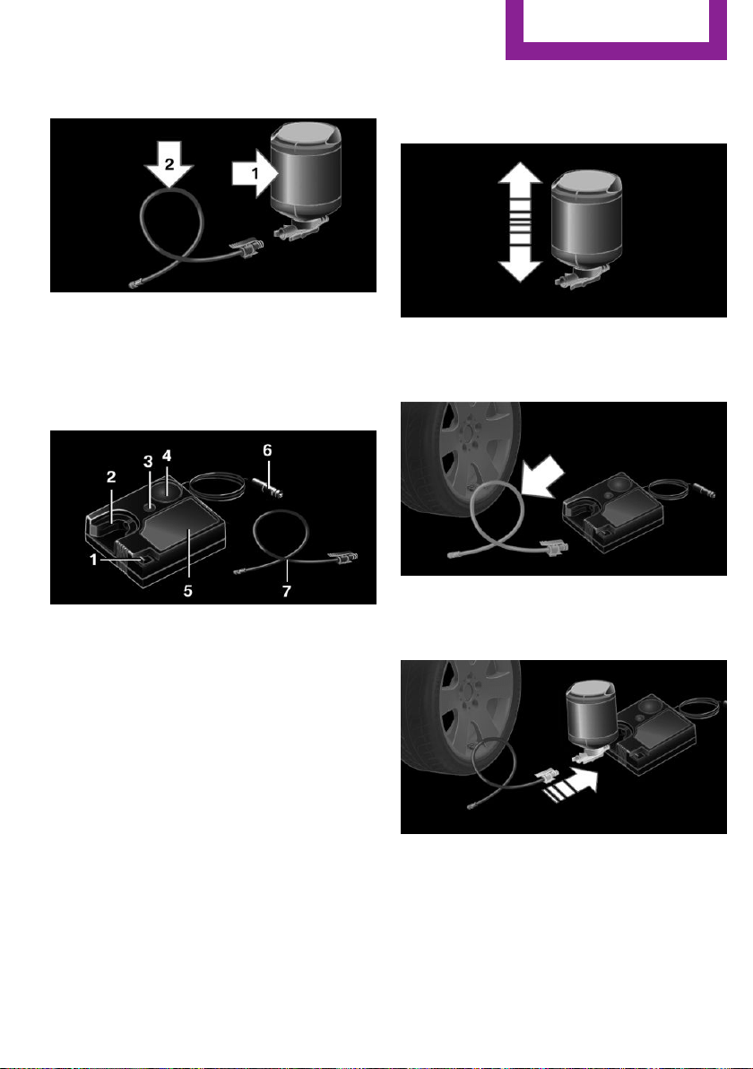
Sealant container
▷ Sealant container, arrow 1.
▷ Filling hose, arrow 2.
Observe use-by date on the sealant container.
Compressor
1 On/off switch
2 Holder for bottle
3 Reduce inflation pressure
4 Inflation pressure dial
5 Compressor
6 Connector/cable for socket
7 Connection hose — stowed in the bottom
of the compressor
Filling the tire with sealant
1. Shake the sealant container.
2. Take the connection hose completely out of
the compressor housing. Do not kink the
hose.
3. Attach the connection hose to the connec‐
tor of the sealant container, ensuring that it
engages audibly.
Seite 189
Wheels and tires
MOBILITY
189
Online Edition for Part no. 01 40 2 963 307 - VI/15
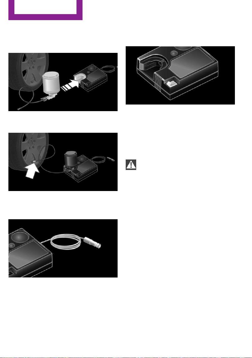
4. Slide the sealant container upright into the
holder on the compressor housing, ensur‐
ing that it engages audibly.
5. Screw the connection hose onto the tire
valve of the nonworking wheel.
6. With the compressor switched off, insert
the plug into a power socket inside the ve‐
hicle.
7. With the ignition turned on or the engine
running, switch on the compressor.
Let the compressor run for approx. 3 to 8 mi‐
nutes to fill the tire with sealant and achieve a
tire inflation pressure of approx. 2.5 bar.
While the tire is being filled with sealant, the
tire inflation pressure may sporadically reach
approx. 5 bar. Do not switch off the compressor
at this point.
CAUTION
The compressor can overheat during ex‐
tended operation. There is risk of property
damage. Do not run the compressor for more
than 10 min.◀
If a tire inflation pressure of 2 bar is not
reached:
1.
Switch off the compressor.
2. Unscrew the filling hose from the wheel.
3. Drive forward and back to distribute the
sealant in the tire.
4. Inflate the tire again using the compressor.
If a tire inflation pressure of 2 bar cannot be
reached, contact your dealer’s service cen‐
ter or another qualified service center or re‐
pair shop.
Stowing the Mobility System
1.
Remove the connection hose of the sealant
container from the wheel.
2. Remove the connection hose from the seal‐
ant container.
Seite 190
MOBILITY
Wheels and tires
190
Online Edition for Part no. 01 40 2 963 307 - VI/15
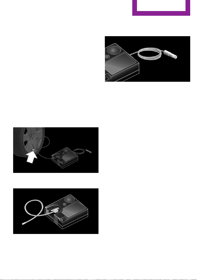
3. Wrap the empty sealant container and con‐
nection hose in suitable material to avoid
dirtying the trunk.
4. Stow the Mobility System back in the vehi‐
cle.
Distributing the sealant
Immediately drive approx. 5 mls/10 km/h to
ensure that the sealant is evenly distributed in
the tire.
Do not exceed a speed of 50 mph/80 km/h.
If possible, do not drive at speeds less than
12 mph/20 km/h.
To correct the tire inflation pressure
1.
Stop at a suitable location.
2. Screw the connection hose onto the tire
valve stem.
3. Attach the connection hose directly to the
compressor.
4. Insert the connector into a power socket in‐
side the vehicle.
5. Correct the tire inflation pressure to 2.5 bar.
▷ Increase pressure: with the ignition
turned on or the engine running, switch
on the compressor.
▷ To reduce the pressure: press the but‐
ton on the compressor.
Continuing the trip
Do not exceed the maximum permissible speed
of 50 mph/80 km/h.
Reinitialize the Flat Tire Monitor, refer to
page 88.
Reinitialize the Tire Pressure Monitor, refer to
page 84.
Replace the nonworking tire and the sealant
container of the Mobility System as soon as
possible.
Snow chains
Fine-link snow chains
The manufacturer of your vehicle recommends
use of fine-link snow chains. Certain types of
fine-link snow chains have been tested by the
manufacturer of the vehicle and recommended
as road-safe and suitable.
Information regarding suitable snow chains is
available from a dealer’s service center or an‐
other qualified service center or repair shop.
Seite 191
Wheels and tires
MOBILITY
191
Online Edition for Part no. 01 40 2 963 307 - VI/15

Use
Use only in pairs on the front wheels, equipped
with the tires of the following size:
▷ 175/65 R 15.
▷ 175/60 R 16.
John Cooper Works:
▷ 185/50 R 17.
Follow the chain manufacturer's instructions.
Make sure that the snow chains are always suf‐
ficiently tight. Retighten as needed according
to the chain manufacturer's instructions.
Do not initialize the Flat Tire Monitor after
mounting snow chains, as doing so may result
in incorrect readings.
Do not initialize the Tire Pressure Monitor after
mounting snow chains, as doing so may result
in incorrect readings.
When driving with snow chains, briefly activate
Dynamic Traction Control if needed.
Maximum speed with snow chains
Do not exceed a speed of 30 mph/50 km/h
when using snow chains.
Seite 192
MOBILITY
Wheels and tires
192
Online Edition for Part no. 01 40 2 963 307 - VI/15

Engine compartment
Vehicle features and op‐
tions
This chapter describes all standard, country-
specific and optional features offered with the
series. It also describes features that are not
necessarily available in your car, e. g., due to
the selected options or country versions. This
also applies to safety-related functions and sys‐
tems. The respectively applicable country provi‐
sions must be observed when using the respec‐
tive features and systems.
Important features in the engine comp.
1 Washer fluid reservoir
2 Vehicle identification number
3 Oil filler neck
4 Jump-starting, positive terminal
5 Jump-starting, negative terminal
6 Coolant reservoir
Seite 193
Engine compartment
MOBILITY
193
Online Edition for Part no. 01 40 2 963 307 - VI/15
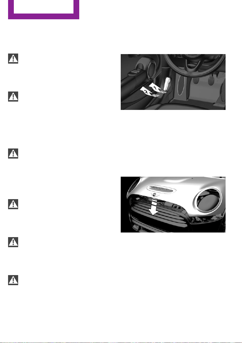
Hood
Information
WARNING
Improperly executed work in the engine
compartment can damage components and
lead to a safety risk. There is risk of accidents or
risk of property damage.◀
WARNING
The engine compartment accommodates
moving components. Certain components can
move in the engine compartment with the ve‐
hicle switched off, e.g. the cooler fan. There is
risk of injuries. Do not reach into the area of
moving parts. Keep articles of clothing and hair
away from moving parts.◀
CAUTION
Folded-away wipers can be jammed
when the hood is opened. There is risk of prop‐
erty damage. Make sure that the wipers with
the wiper blades mounted are folded down
onto the windshield before opening the
hood.◀
WARNING
There are protruding parts, e.g. lock
hook, on the inside of the hood. There is risk of
injuries. If the hood is open, pay attention to
protruding parts and keep these areas clear.◀
WARNING
An incorrectly locked hood can open
while driving and restrict visibility. There is risk
of an accident. Stop immediately and correctly
close the hood.◀
WARNING
Body parts can be jammed on opening
and closing the hood. There is risk of injuries.
Make sure that the area of movement of the
hood is clear during opening and closing.◀
Opening the hood
1. Pull lever, arrow 1.
Hood is unlocked.
2. After the lever is released, pull the lever
again, arrow 2.
Hood can be opened.
Indicator/warning lights
When the hood is opened, a Check Control
message is displayed.
Closing the hood
Let the hood fall from approx. 16 in/40 cm, ar‐
row.
The hood must audibly engage on both sides.
Seite 194
MOBILITY
Engine compartment
194
Online Edition for Part no. 01 40 2 963 307 - VI/15

Engine oil
Vehicle features and op‐
tions
This chapter describes all standard, country-
specific and optional features offered with the
series. It also describes features that are not
necessarily available in your car, e. g., due to
the selected options or country versions. This
also applies to safety-related functions and sys‐
tems. The respectively applicable country provi‐
sions must be observed when using the respec‐
tive features and systems.
General information
The engine oil consumption is dependent on
the driving style and driving conditions.
The engine oil consumption can increase in the
following situations, for example:
▷ Sporty driving style.
▷ Break-in of the engine.
▷ Idling of the engine.
▷ With use of engine oil types that are not ap‐
proved.
Therefore, regularly check the engine oil level
after refueling.
The vehicle is equipped with electronic oil
measurement.
The electronic oil measurement has two meas‐
uring principles:
▷ Status display.
▷ Detailed measurement.
Electronic oil measure‐
ment
Status display
The concept
The engine oil level is monitored electronically
while driving and shown on the radio display.
If the engine oil level reaches the minimum
level, a check control message is displayed.
Requirements
A current measured value is available after ap‐
prox. 30 minutes of driving. During a shorter
trip, the status of the last, sufficiently long trip is
displayed.
With frequent short-distance trips, perform a
detailed measurement.
Displaying the engine oil level
1. Press button.
2. "Vehicle Info"
3. "Vehicle status"
4. "Engine oil level"
The engine oil level is displayed.
Engine oil level display messages
Different messages appear on the display de‐
pending on the engine oil level. Pay attention
to these messages.
If the engine oil level is too low within the next
125 miles/200 km, add engine oil, refer to
page 196.
CAUTION
A too low engine oil level causes engine
damage. There is risk of property damage. Im‐
mediately add engine oil.◀
Seite 195
Engine oil
MOBILITY
195
Online Edition for Part no. 01 40 2 963 307 - VI/15

Take care not to add too much engine oil.
CAUTION
Too much engine oil can damage the en‐
gine or the catalytic converter. There is risk of
property damage. Do not add too much engine
oil. Have too much engine oil siphoned off by a
dealer’s service center or another qualified
service center or repair shop.◀
Detailed measurement
The concept
In the detailed measurement the engine oil
level is checked and displayed via a scale.
If the engine oil level reaches the minimum
level, a check control message is displayed.
During the measurement, the idle speed is in‐
creased somewhat.
Requirements
▷ Vehicle is on level road.
▷ Manual transmission: shift lever in neutral
position, clutch and accelerator pedals not
depressed.
▷ Steptronic transmission: selector lever in se‐
lector lever position N or P and accelerator
pedal not depressed.
▷ Engine is running and is at operating tem‐
perature.
Performing a detailed measurement
In order to perform a detailed measurement of
the engine oil level:
Confirm message regarding engine oil level dis‐
play.
The engine oil level is checked and displayed
via a scale.
Time: approx. 1 minute.
Adding engine oil
Information
CAUTION
A too low engine oil level causes engine
damage. There is risk of property damage.
Add engine oil within the next
125 miles/200 km.◀
CAUTION
Too much engine oil can damage the en‐
gine or the catalytic converter. There is risk of
property damage. Do not add too much engine
oil. Have too much engine oil siphoned off by a
dealer’s service center or another qualified
service center or repair shop.◀
WARNING
Operating materials, e.g. oils, greases,
coolants, fuels, can contain harmful ingredi‐
ents. There is risk of injuries or danger to life.
Observe the instructions on the containers.
Avoid the contact of articles of clothing, skin or
eyes with operating materials. Do not refill op‐
erating materials into different bottles. Store
operating materials out of reach of children.◀
General information
Only add engine oil when the message is dis‐
played in the instrument cluster. The quantity
to be added is indicated in the message dis‐
played in the instrument cluster.
Switch off the ignition and safely park the vehi‐
cle before engine oil is added.
Overview
The oil filler neck is located in the engine com‐
partment, refer to page 193.
Opening the oil filler neck
1.
Open the hood, refer to page 194.
Seite 196
MOBILITY
Engine oil
196
Online Edition for Part no. 01 40 2 963 307 - VI/15
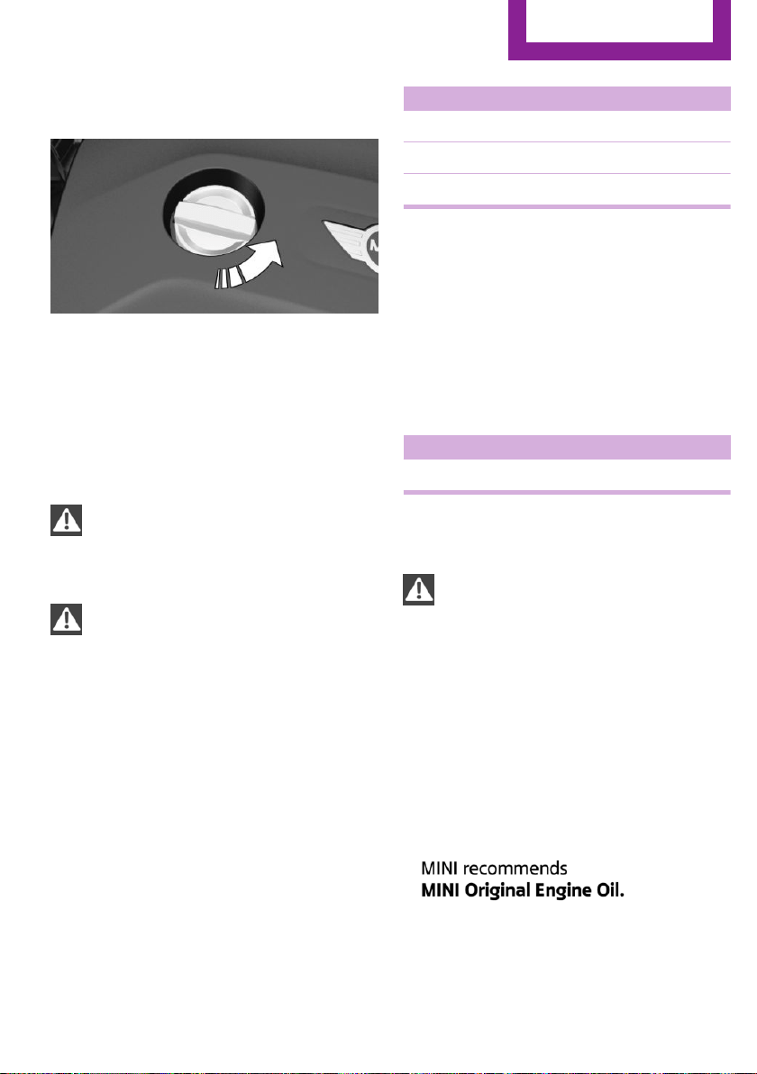
2. Turn the oil filler neck counter-clockwise,
arrow.
3. Add motor oil.
After refilling, perform a detailed measure‐
ment, refer to page 196.
Engine oil types to add
Information
CAUTION
Oil additives can damage the engine.
There is risk of property damage. Do not use oil
additives.◀
CAUTION
Incorrect engine oil can cause malfunc‐
tions in the engine or damage it. There is risk of
property damage. When selecting an engine
oil, make sure that the engine oil has the cor‐
rect viscosity grade.◀
The engine oil quality is critical for the life of the
engine.
Viscosity grades
When selecting an engine oil, ensure that the
engine oil belongs to one of the viscosity
grades SAE 0W-40, SAE 0W-30, SAE 5W-40, SAE
5W-30, 0W-20 or 5W-20.
Suitable engine oil types
Add engine oils that meet the following oil rat‐
ing standards:
Gasoline engine
BMW Longlife-01.
BMW Longlife-01 FE.
BMW Longlife-14 FE+.
More information about suitable engine oil rat‐
ings and viscosities of engine oils can be re‐
quested from a dealer’s service center or an‐
other qualified service center or repair shop.
Alternative engine oil types
If an engine oil suitable for continuous use is
not available, up to 1 US quart/liter of an en‐
gine oil with the following oil rating can be
added:
Gasoline engine
API SL or superior oil rating
Engine oil change
CAUTION
Engine oil that is not changed in timely
fashion can cause increased engine wear and
thus engine damage. There is risk of property
damage. Do not exceed the service data indi‐
cated in the vehicle.◀
The vehicle manufacturer recommends that
you let the dealer’s service center or another
qualified service center or repair shop change
the motor oil.
Seite 197
Engine oil
MOBILITY
197
Online Edition for Part no. 01 40 2 963 307 - VI/15
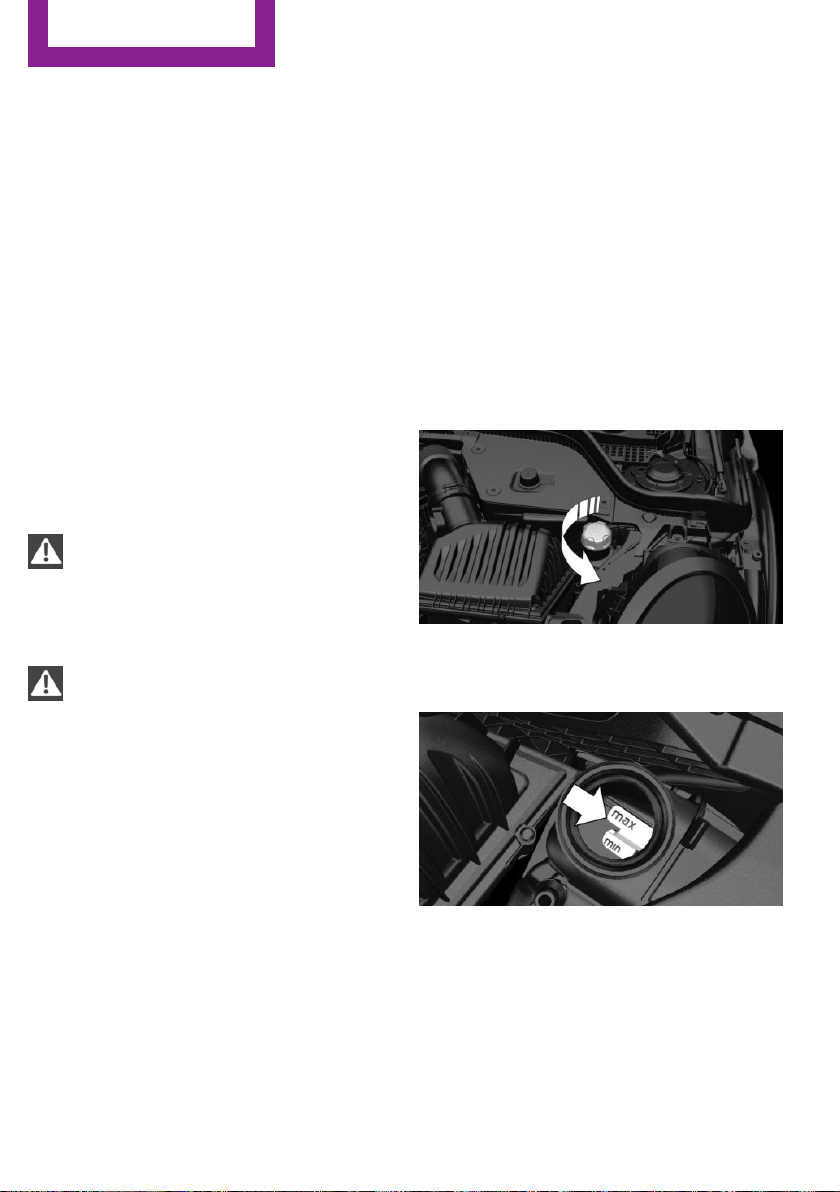
Coolant
Vehicle features and op‐
tions
This chapter describes all standard, country-
specific and optional features offered with the
series. It also describes features that are not
necessarily available in your car, e. g., due to
the selected options or country versions. This
also applies to safety-related functions and sys‐
tems. The respectively applicable country provi‐
sions must be observed when using the respec‐
tive features and systems.
Information
WARNING
With the engine hot and the cooling sys‐
tem open, coolant can escape and lead to
burns. There is risk of injuries. Only open the
cooling system with the engine cooled down.◀
WARNING
Additives are harmful and incorrect addi‐
tives can damage the engine. There is risk of in‐
juries and risk of property damage. Avoid the
contact of articles of clothing, skin or eyes with
additives. Do not swallow any additives. Use
suitable additives only.◀
Coolant consists of water and additives.
Not all commercially available additives are
suitable for the vehicle. Information about suit‐
able additives is available from a dealer’s serv‐
ice center or another qualified service center or
repair shop.
Coolant level
Overview
Opening the hood, refer to page 194
The coolant reservoir is in the engine compart‐
ment, refer to page 193.
Checking
There are yellow Min and Max marks in the
coolant reservoir.
1. Let the engine cool.
2. Turn the lid of the coolant reservoir slightly
counterclockwise to allow any excess pres‐
sure to dissipate, then open it.
3. The coolant level is correct if it lies between
the minimum and maximum marks in the
filler neck.
Seite 198
MOBILITY
Coolant
198
Online Edition for Part no. 01 40 2 963 307 - VI/15
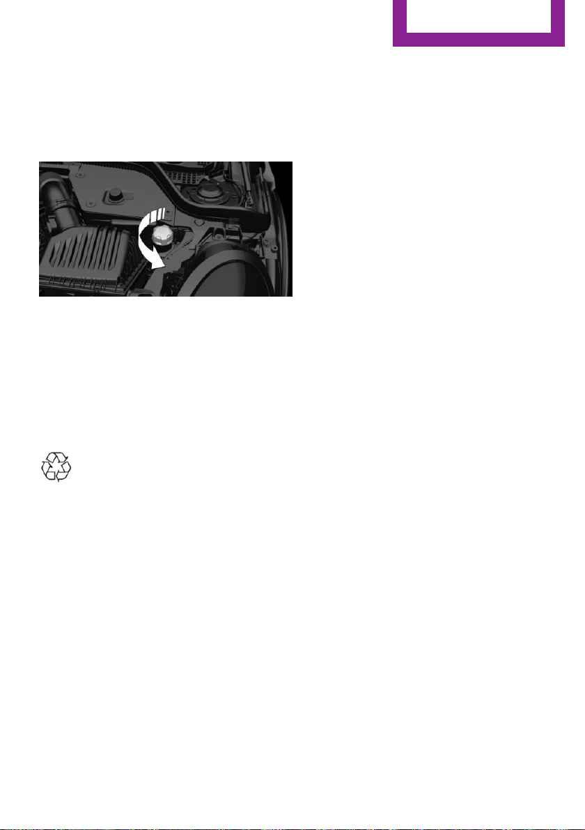
Adding
1. Let the engine cool.
2. Turn the lid of the coolant reservoir slightly
counterclockwise to allow any excess pres‐
sure to dissipate, then open it.
3. If the coolant is low, slowly add coolant up
to the specified level; do not overfill.
4. Close cap.
5. Have the cause of the coolant loss elimi‐
nated as soon as possible.
Disposal
Comply with the relevant environmen‐
tal protection regulations when dispos‐
ing of coolant and coolant additives.
Seite 199
Coolant
MOBILITY
199
Online Edition for Part no. 01 40 2 963 307 - VI/15

Maintenance
Vehicle features and op‐
tions
This chapter describes all standard, country-
specific and optional features offered with the
series. It also describes features that are not
necessarily available in your car, e. g., due to
the selected options or country versions. This
also applies to safety-related functions and sys‐
tems. The respectively applicable country provi‐
sions must be observed when using the respec‐
tive features and systems.
MINI maintenance system
The maintenance system indicates required
maintenance measures, and thereby provides
support in maintaining road safety and the op‐
erational reliability of the vehicle.
In some cases scopes and intervals may vary
according to the country-specific version. Re‐
placement work, spare parts, fuels and lubri‐
cants and wear materials are calculated sepa‐
rately. Further information is available from a
dealer’s service center or another qualified
service center or repair shop.
Condition Based Service
CBS
Sensors and special algorithms take into ac‐
count the driving conditions of your vehicle.
Based on this, Condition Based Service recog‐
nizes the maintenance requirements.
The system makes it possible to adapt the
amount of maintenance corresponding to your
user profile.
Detailed information on service requirements,
refer to page 68, can be displayed on the radio.
Service data in the remote control
Information on the required maintenance is
continuously stored in the remote control. The
dealer’s service center can read this data out
and suggest an optimized maintenance scope
for your vehicle.
Therefore, hand the service advisor the remote
control with which the vehicle was driven most
recently.
Storage periods
Storage periods during which the vehicle bat‐
tery was disconnected are not taken into ac‐
count.
If this occurs, have a dealer's service center or
another qualified service center or repair shop
update the time-dependent maintenance pro‐
cedures, such as checking brake fluid and, if
necessary, changing the engine oil and the mi‐
crofilter/activated-charcoal filter.
Service and Warranty In‐
formation Booklet for
US models and Warranty
and Service Guide Book‐
let for Canadian models
Please consult your Service and Warranty Infor‐
mation Booklet for US models and Warranty
and Service Guide Booklet for Canadian models
for additional information on service require‐
ments.
The manufacturer of your vehicle recommends
that maintenance and repair be performed by a
dealer’s service center or another qualified
service center or repair shop. Records of regu‐
lar maintenance and repair work should be re‐
tained.
Seite 200
MOBILITY
Maintenance
200
Online Edition for Part no. 01 40 2 963 307 - VI/15
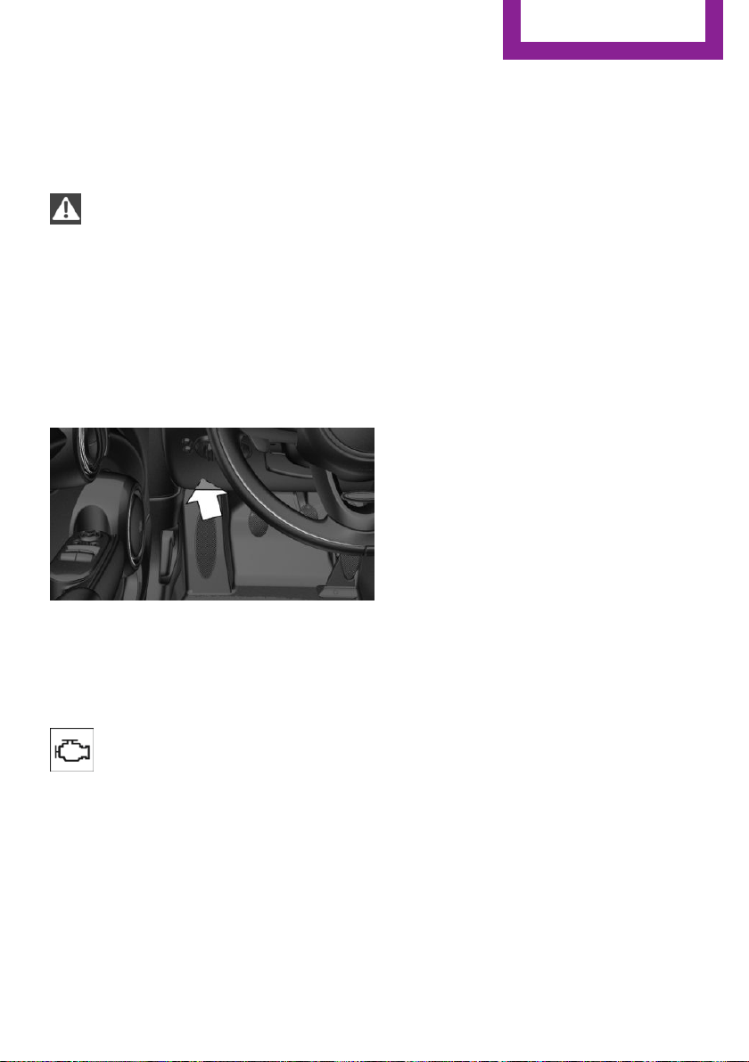
Socket for OBD Onboard
Diagnosis
Information
CAUTION
Improper use of the socket for Onboard
Diagnosis can lead to vehicle malfunctions.
There is risk of property damage. The manufac‐
turer of your vehicle strongly recommends ac‐
cess to the socket for Onboard Diagnosis be
limited to a dealer's service center, another
qualified service center or repair shop or other
authorized persons.◀
Position
There is an OBD socket on the driver's side for
checking the primary components in the vehi‐
cle's emissions.
Emissions
▷ The warning lamp lights up:
Emissions are deteriorating. Have
the vehicle checked as soon as pos‐
sible.
▷ The warning lamp flashes under certain cir‐
cumstances:
This indicates that there is excessive misfir‐
ing in the engine.
Reduce the vehicle speed and have the sys‐
tem checked immediately; otherwise, seri‐
ous engine misfiring within a brief period
can seriously damage emission control
components, in particular the catalytic con‐
verter.
Seite 201
Maintenance
MOBILITY
201
Online Edition for Part no. 01 40 2 963 307 - VI/15
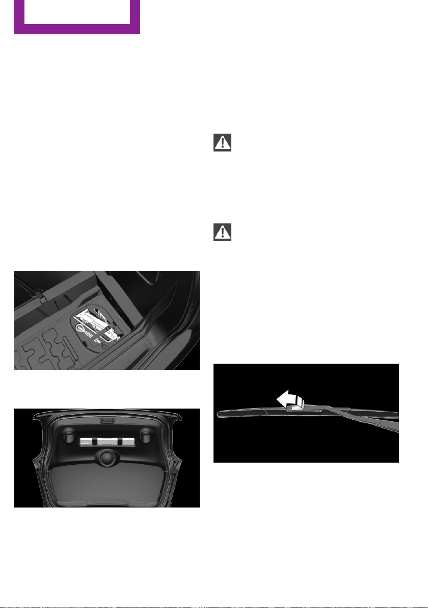
Replacing components
Vehicle features and op‐
tions
This chapter describes all standard, country-
specific and optional features offered with the
series. It also describes features that are not
necessarily available in your car, e. g., due to
the selected options or country versions. This
also applies to safety-related functions and sys‐
tems. The respectively applicable country provi‐
sions must be observed when using the respec‐
tive features and systems.
Onboard vehicle tool kit
The onboard vehicle tool kit is located in the
trough under the trunk floor.
The warning triangle is located in the tailgate.
To remove, loosen the brackets.
Wiper blade replacement
Information
CAUTION
If the wiper arm falls onto the windshield
without the wiper blades installed, the wind‐
shield can be damaged. There is risk of prop‐
erty damage. Secure the wiper arm when re‐
placing the wiper blades and do not fold down
the wipers without the wiper blades installed.◀
CAUTION
Folded-away wipers can be jammed
when the hood is opened. There is risk of prop‐
erty damage. Make sure that the wipers with
the wiper blades mounted are folded down
onto the windshield before opening the
hood.◀
Replacing the front wiper blades
1.
Fold up and hold the wiper arm firmly.
2. Open the wiper blade lock, arrow.
3. Pull the wiper blade down first out of the
holder on the wiper arm, arrow 1.
Seite 202
MOBILITY
Replacing components
202
Online Edition for Part no. 01 40 2 963 307 - VI/15
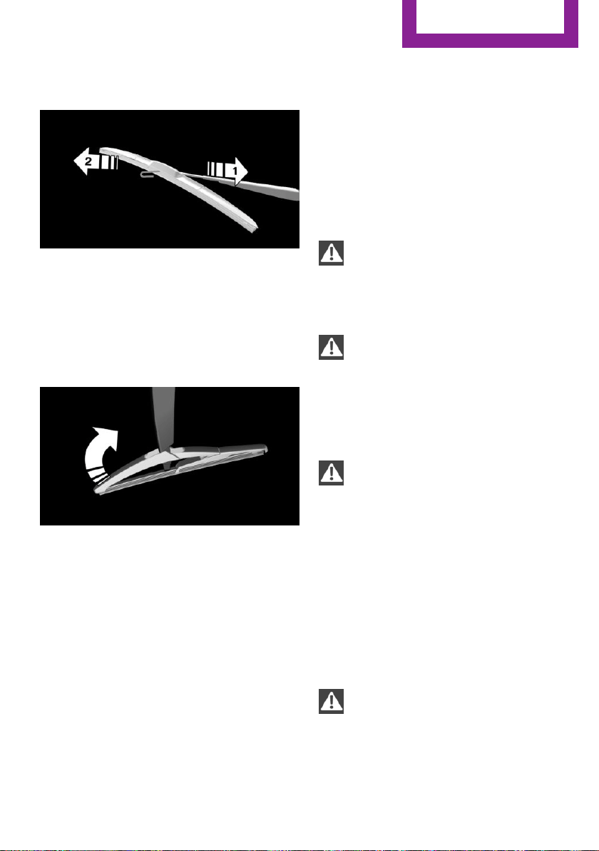
Then pull the wiper blade free from the
holder of the wiper arm, arrow 2.
4. Insert and latch a new wiper blade in re‐
verse order.
5. Fold down the wipers.
Replace rear wiper blade
1.
Fold up and hold the wiper arm firmly.
2. Turn the wiper blade all the way back.
3. Continue turning the wiper blade all the
way so that it pops out of the holder.
4. Press the new wiper blade into the holder
until you hear it snap into place.
5. Fold the wipers in.
Lamp and bulb replace‐
ment
General information
Lights and bulbs make an essential contribution
to vehicle safety.
The manufacturer of the vehicle recommends
that you have appropriate work performed by a
dealer’s service center or another qualified
service center or repair shop if you are unfami‐
liar with it or if it has not been described here.
A spare lamp box is available from a dealer’s
service center or another qualified service cen‐
ter or repair shop.
Information
Lights and bulbs
WARNING
Bulbs can get hot during operation. Con‐
tact with the bulbs can cause burns. There is
risk of injuries. Only change bulbs after they
have cooled off.◀
WARNING
Work on switched-on lighting systems
can cause short circuits. There is risk of injuries
or risk of property damage. When working on
the lighting system, switch off the lamps in
question. If necessary, heed the bulb manufac‐
turer's instructions.◀
CAUTION
Contaminated bulbs reduce their service
life. There is risk of property damage. Do not
hold new bulbs with your bare hands. Use a
clean cloth or something similar, or hold the
bulb by its base.◀
Light-emitting diodes (LEDs)
Some items of equipment use light-emitting di‐
odes installed behind a cover as a light source.
These light-emitting diodes, which are related
to conventional lasers, are officially designated
as Class 1 light-emitting diodes.
WARNING
Too intensive brightness can irritate or
damage the retina of the eye. There is risk of
injuries. Do not look directly into the headlights
or other light sources for an extended period of
time. Do not remove the LED covers.◀
Seite 203
Replacing components
MOBILITY
203
Online Edition for Part no. 01 40 2 963 307 - VI/15
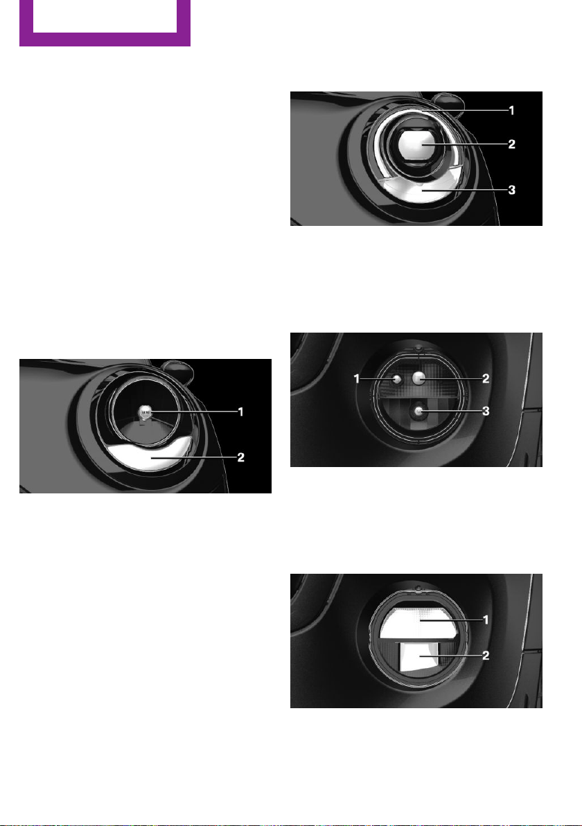
Headlight glass
Condensation can form on the inside of the ex‐
ternal lights in cool or humid weather. When
driving with the lights switched on, the conden‐
sation evaporates after a short time. The head‐
light glass does not need to be changed.
If despite driving with the lights switched on,
increasing humidity forms, e. g. water droplets
in the lamp, the manufacturer of your vehicle
recommends having it checked by a dealer’s
service center or another qualified service cen‐
ter or repair shop.
Front lights, bulb replacement
Overview
Halogen headlights
1 Low beams/high beams
2 Turn signal
LED headlights
1 Daytime running lights
2 Low beams/high beams
3 Turn signal
Bug light
1 Parking lights
2 Daytime running lights
3 Fog lights
LED bug light
1 Parking lights
2 Fog lights
Seite 204
MOBILITY
Replacing components
204
Online Edition for Part no. 01 40 2 963 307 - VI/15
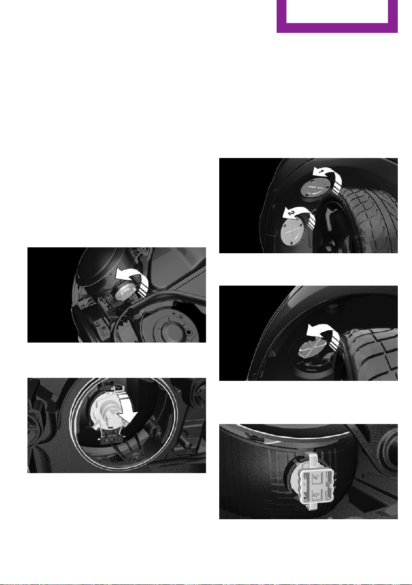
LED low beams/LED high beams
Follow the general instructions on lights and
bulbs, refer to page 203.
The lights feature LED technology. Contact a
dealer’s service center or another qualified
service center or repair shop in the event of a
malfunction.
Halogen low beams/halogen high
beams
Follow the general instructions on lights and
bulbs, refer to page 203.
Bulbs: H4
1.
Open the hood, refer to page 194.
2. Turn the lid counterclockwise, arrow, and
remove.
3. Pull off the connector.
4. Unclip spring clip, arrow, and fold down.
5. Remove the bulb from the headlight hous‐
ing.
6. Insert the new bulb and install the cover in
the reverse order.
Turn signal
Follow the general instructions on lights and
bulbs, refer to page 203.
Bulbs: PW24W
With white turn signal lights: PWY24W
1. Turn the steering wheel.
2. Turn the lid counterclockwise, arrow 1, and
remove.
3. Unscrew the inner lid counterclockwise,
and remove it.
4. Pull bulb holder out of the bulb housing; if
needed, loosen it with small tilting move‐
ments if possible.
Seite 205
Replacing components
MOBILITY
205
Online Edition for Part no. 01 40 2 963 307 - VI/15
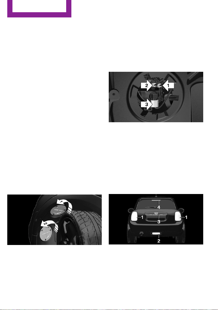
5. Pull the bulb out of the fixture.
6. Insert the new bulb and install the cover in
the reverse order.
LED parking lights/LED fog lights
Follow the general instructions on lights and
bulbs, refer to page 203.
The lights feature LED technology. Contact a
dealer’s service center or another qualified
service center or repair shop in the event of a
malfunction.
Parking lights/fog lights/daytime
running lights
Follow the general instructions on lights and
bulbs, refer to page 203.
Bulbs:
▷ Parking lights for halogen headlights: W5W
Parking lights for LED headlights: W5W NBV
▷ Daytime running light: PSX24W
▷ Fog lamp: H8
Replacing the bulbs
1.
Turn the steering wheel.
2. Turn the lid counterclockwise, arrow 2, and
remove.
3. Remove the corresponding connector.
4. Remove the bulb holder.
▷ Turn the parking light bulb holder coun‐
ter-clockwise, arrow 1, and remove.
▷ Press together the upper and lower
locking of the daytime running lights
bulb holder, arrow 2, and remove the
bulb holder.
For better accessibility, if needed, re‐
move the bulb of the fog lamp before‐
hand.
▷ Turn the fog light bulb holder counter-
clockwise, arrow 3, and remove.
5. Pull the bulb out of the fixture.
6. Insert the new bulb and install the cover in
the reverse order.
The daytime running lights bulb holder en‐
gages audibly, first below, then above.
Tail lights, bulb replacement
Overview
Vehicles with a rear fog lamp
1 Side tail lights
2 Rear fog lamp
3 License plate lamp
4 Center brake lamp
Seite 206
MOBILITY
Replacing components
206
Online Edition for Part no. 01 40 2 963 307 - VI/15
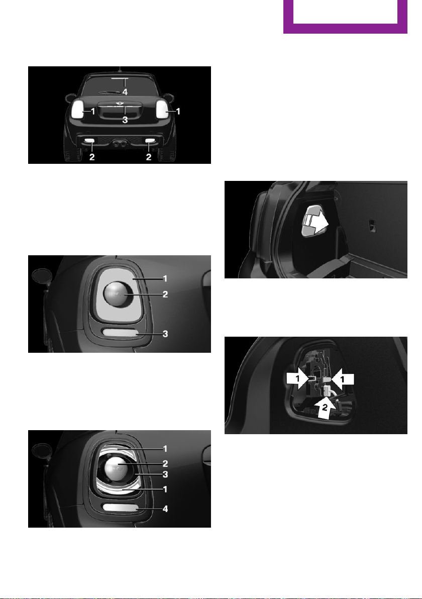
Vehicle with two rear fog lights
1 Side tail lights
2 Rear fog lights
3 License plate lamp
4 Center brake lamp
Side tail lights
1 Brake lights/tail lights
2 Turn signal
3 Reversing lights
Side LED tail lights
1 Tail lights
2 Turn signal
3 Brake light
4 Reversing lights
Side tail lights
Follow the general instructions on lights and
bulbs, refer to page 203.
Bulbs: P21W
1. Open tailgate, refer to page 27.
2. Remove left or right cover.
3. Through the opening, loosen the plug con‐
nector, arrow 2 on the bulb holder.
Press the latches together, arrows 1, and
remove the bulb holder.
4. Remove the bulb holder from the opening.
5. Press the nonworking bulb gently into the
socket, turn counterclockwise and remove.
▷ Arrow 1: brake lights/tail lights
▷ Arrow 2: turn signal
Seite 207
Replacing components
MOBILITY
207
Online Edition for Part no. 01 40 2 963 307 - VI/15
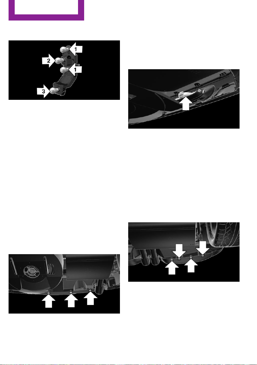
▷ Arrow 3: reversing light
6. Proceed in the reverse order to insert the
new bulb and attach the bulb holder. Make
sure that the bulb holder engages in all fas‐
teners.
Central brake lamp and license plate
lamp
Follow the general instructions on lights and
bulbs, refer to page 203.
The lights feature LED technology. Contact a
dealer’s service center or another qualified
service center or repair shop in the event of a
malfunction.
Vehicles with a rear fog lamp
Follow the general instructions on Lights and
bulbs, refer to page 203.
Bulbs: W16W
1.
On vehicles with heat shield:
Loosen 3 screws, arrow.
2. Push the heat shield forward and the
bumper back in order to be able to reach
the fog lamp.
3. Turn the bulb socket counterclockwise and
remove.
The wire is long enough to guide the socket
down and through between any heat shield
that may be installed and the bumper.
4. Replace nonworking bulb.
5. To install the new bulb, proceed in reverse
order of removal.
Vehicle with two rear fog lights
Follow the general instructions on Lights and
bulbs, refer to page 203.
Bulbs: W16W
Left rear fog lamp:
1.
On vehicles with heat shield:
Loosen 3 screws, arrow.
2. Push the heat shield forward and the
bumper back in order to be able to reach
the fog lamp.
3. Turn the bulb socket counterclockwise and
remove.
Seite 208
MOBILITY
Replacing components
208
Online Edition for Part no. 01 40 2 963 307 - VI/15
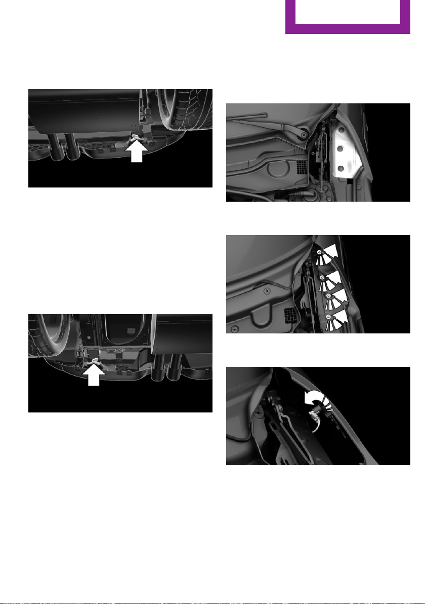
The wire is long enough to guide the socket
down and through between any heat shield
that may be installed and the bumper.
4. Replace nonworking bulb.
5. To install the new bulb, proceed in reverse
order of removal.
Right fog lamp:
1.
Turn the bulb socket counterclockwise and
remove.
The wire is long enough to guide the socket
down and through between any heat shield
that may be installed and the bumper.
2. Replace nonworking bulb.
3. To install the new bulb, proceed in reverse
order of removal.
Side turn signal, bulb replacement
Follow the general instructions on lights and
bulbs, refer to page 203.
Bulbs:
▷ With orange lens: W5W
▷ With white lens: WY5W diadem
1. Open the hood. The covers of the side turn
signal lights are on the left and right next to
the hinges of the hood.
2. Loosen nuts of the cover by hand and re‐
move the cover.
3. Turn the bulb holder counterclockwise and
remove.
4. Replace the bulb.
5. To insert the new bulb, proceed in reverse
order of removal. Insert the nuts of the
cover and press down.
Seite 209
Replacing components
MOBILITY
209
Online Edition for Part no. 01 40 2 963 307 - VI/15
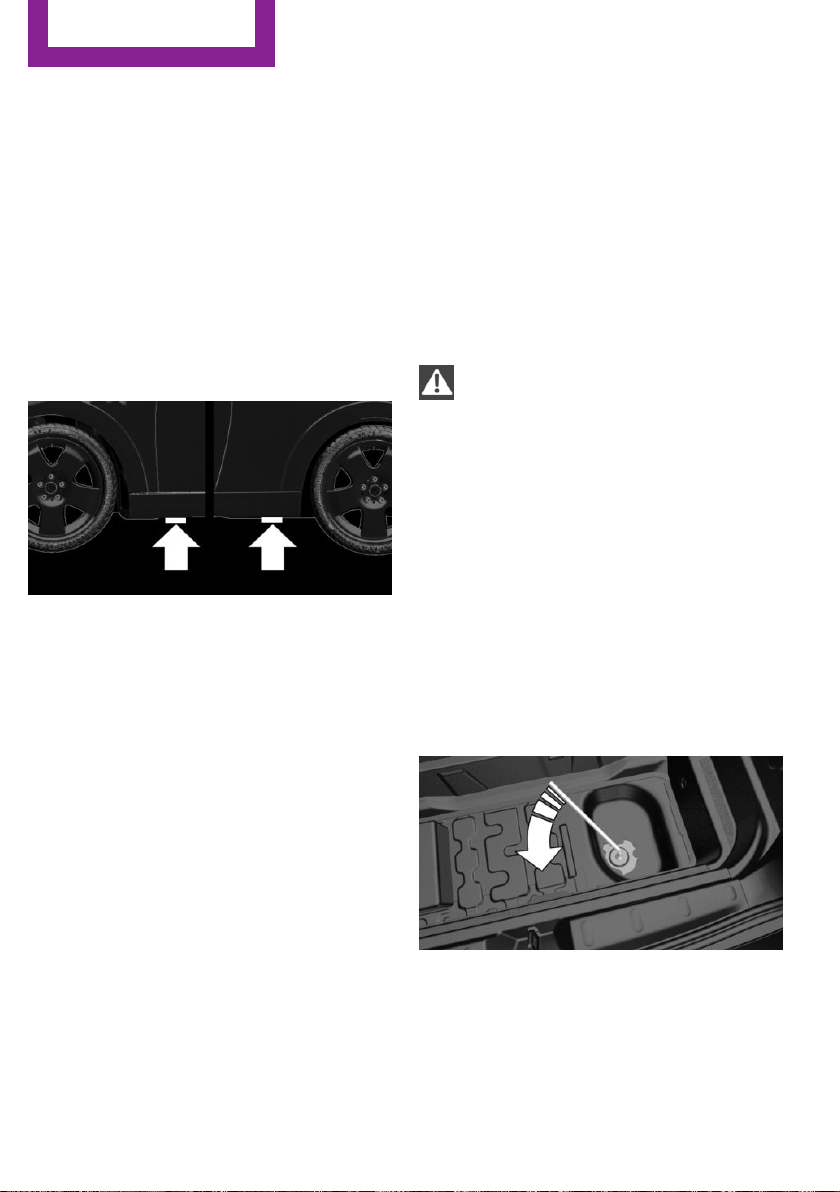
Changing wheels
Information
When using run-flat tires or tire sealants, a tire
does not need to be changed immediately in
the event of pressure loss due to a flat tire.
Which is why no spare tire is available.
The tools for changing wheels are available as
accessories from your dealer’s service center or
another qualified service center or repair shop.
Jacking points for the vehicle jack
The jacking points for the vehicle jack are lo‐
cated at the positions shown.
Emergency wheel
Safety measures
▷ Park the vehicle as far away as possible
from passing traffic and on solid ground.
Switch on the hazard warning system.
▷ Set the parking brake and engage lever in
position P P.
▷ Have all vehicle occupants get out of the
vehicle and ensure that they remain out‐
side the immediate area in a safe place,
such as behind a guardrail.
▷ If necessary, set up a warning triangle or
portable hazard warning lamp at an appro‐
priate distance.
▷ Perform wheel change only on a flat, solid
and slip-resistant surface. On soft or slip‐
pery ground, e.g., snow, ice, tiles, etc., the
vehicle or vehicle jack can slip away to the
side.
▷ Do not place wood blocks or similar items
under the vehicle jack; otherwise, it cannot
reach its carrying capacity because of the
restricted height.
▷ If the vehicle is raised, do not lie under the
vehicle and do not start the engine; other‐
wise, a fatal hazard exists.
Information
WARNING
The vehicle jack is optimized for lifting
the vehicle and for the jacking points on the ve‐
hicle only. There is risk of injuries. Do not lift
any other vehicle or cargo using the vehicle
jack.◀
Removing the emergency wheel
The emergency wheel is housed in a well on
the underbody of the vehicle. The screw con‐
nection of the emergency wheel is in the cargo
area underneath the floor mat, on the floor of
the storage compartment for the onboard vehi‐
cle tool kit.
1.
Loosen the nut using the wheel wrench
from the onboard vehicle tool kit.
2. Remove the retaining plate.
Seite 210
MOBILITY
Replacing components
210
Online Edition for Part no. 01 40 2 963 307 - VI/15
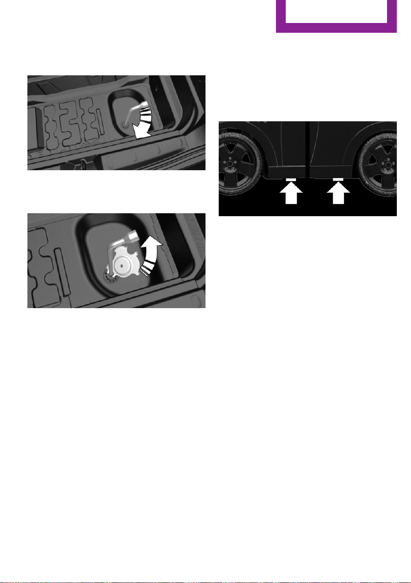
3. Screw wheel lug wrench onto the thread
and hold in place with one hand.
4. Unlock the locking hexagon of the emer‐
gency wheel well using the hexagon at‐
tached to retaining plate.
5. Lower the emergency wheel with the wheel
wrench.
6. Unscrewing the wheel wrench
7. Pull out the well with emergency wheel un‐
der the vehicle toward the rear.
8. Remove the spacer and emergency wheel
from the well.
9. Stow the well and spacer in the vehicle.
Prepare wheel change
1.
Follow the Safety instructions, refer to
page 210.
2. With the wheel chock from the onboard ve‐
hicle tool kit, also secure the vehicle against
rolling away at the front wheel of the oppo‐
site side. For this, place the wheel chock
behind the front wheel diagonally across.
3. Loosen the wheel lug bolts a half turn.
Jacking up the vehicle
1. Place the vehicle jack at the jacking point
closest to the wheel such that the vehicle
jack foot is vertically beneath the vehicle
jacking point with the entire surface on the
ground.
2. Insert the vehicle jack head in the rectan‐
gular recess of the jacking point for crank‐
ing it up.
3. Crank it up until the wheel in question lifts
off of the ground.
Wheel mounting
Mount one emergency wheel only.
1.
Unscrew the wheel lug bolts and remove
the wheel.
2. Put the new wheel or emergency wheel on
and screw in at least two bolts.
If original MINI light alloy wheels are not
mounted, any accompanying lug bolts also
have to be used.
3. Screw in the remaining the lug bolts and
tighten all bolts well in a crosswise pattern.
4. Lower the vehicle and remove the vehicle
jack.
After the wheel change
1.
Tighten the lug bolts crosswise. The tight‐
ening torque is 101 lb ft/140 Nm.
2. Stow the nonworking wheel in the trunk.
The nonworking wheel cannot be stored in
the emergency wheel bracket because of
its size.
Seite 211
Replacing components
MOBILITY
211
Online Edition for Part no. 01 40 2 963 307 - VI/15

3. Check tire inflation pressure at the next op‐
portunity and correct as needed.
4. Reinitialize the Flat Tire Monitor, refer to
page 88.
Reinitialize the Tire Pressure Monitor, refer
to page 85.
5. Check to make sure the lug bolts are tight
with a calibrated torque wrench.
Driving with emergency wheel
WARNING
The emergency wheel has particular di‐
mensions. When driving with an emergency
wheel, changed driving properties may occur at
higher speeds, e.g. reduced lane stability when
braking, longer braking distance and changed
self-steering properties in the limit area. There
is risk of an accident. Drive moderately and do
not exceed a speed of 50 mph/80 km/h.◀
After the trip with emergency wheel
Have the following work performed by a deal‐
er's service center or another qualified service
center or repair shop.
1.
Replace the damaged tires as soon as pos‐
sible.
2. Replace the emergency wheel with a new
wheel.
3. Have the tray with the emergency wheel
installed.
Vehicle battery
Maintenance
The battery is maintenance-free.
The added amount of acid is sufficient for the
service life of the battery.
More information about the battery can be re‐
quested from a dealer’s service center or an‐
other qualified service center or repair shop.
Battery replacement
CAUTION
Vehicle batteries that are not compatible
can damage vehicle systems and impair vehicle
functions.There is risk of property damage. In‐
formation on the compatible vehicle batteries is
available at your dealer's service center.◀
After a battery replacement, the manufacturer
of your vehicle recommends that the vehicle
battery be registered on the vehicle by a
dealer’s service center or another qualified
service center or repair shop to ensure that all
comfort features are fully available and that
any Check Control messages of these comfort
features are no longer displayed.
Charging the battery
General information
Make sure that the battery is always sufficiently
charged to guarantee that the battery remains
usable for its full service life.
The battery may need to be charged in the fol‐
lowing cases:
▷ When making frequent short-distance
drives.
▷ If the vehicle is not used for prolonged peri‐
ods, longer than a month.
▷ Steptronic transmission: when parked for
long periods of time in selector lever posi‐
tion D, R or N.
Information
CAUTION
Battery chargers for the vehicle battery
can work with high voltages and currents,
which means that the 12V on-board network
can be overloaded or damaged. There is risk of
property damage. Only connect battery charg‐
ers for the vehicle battery to the starting aid
terminals in the engine compartment.◀
Seite 212
MOBILITY
Replacing components
212
Online Edition for Part no. 01 40 2 963 307 - VI/15
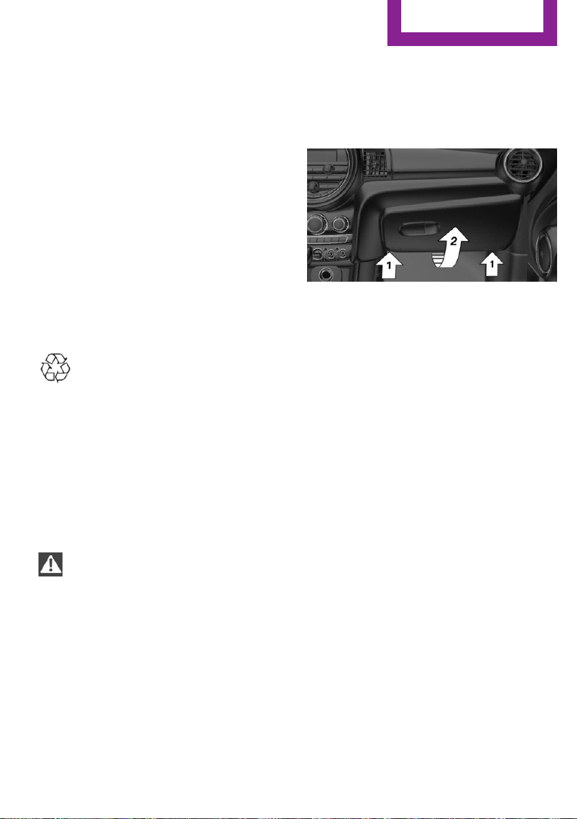
Starting aid terminals
In the vehicle, only charge the battery via the
starting aid terminals, refer to page 215, in the
engine compartment with the engine off.
Power failure
After a temporary power loss, some equipment
needs to be newly initialized or individual set‐
tings updated, e. g.:
▷ Time: update.
▷ Date: update.
▷ Seat and mirror memory: store the posi‐
tions again.
▷ Glass sunroof: initialize the system, refer to
page 35.
Disposing of old batteries
Have old batteries disposed of by a
dealer’s service center or another quali‐
fied service center or repair shop or
take them to a collection point.
Maintain the battery in an upright position for
transport and storage. Secure the battery so
that it does not tip over during transport.
Fuses
Information
WARNING
Incorrect and repaired fuses can overload
electrical lines and components. There is risk of
fire. Never attempt to repair a blown fuse and
do not replace a nonworking fuse with a substi‐
tute of another color or amperage rating.◀
Replacing fuse
The fuses are located in the passenger footwell
under the dashboard.
1. To open, loosen screws, arrow 1.
2. Fold down the fuse holder, arrow 2.
Information on the fuse types and locations
is found on a separate sheet.
3. Replace the fuse in question.
4. The installation is done in reverse order
from the removal.
Seite 213
Replacing components
MOBILITY
213
Online Edition for Part no. 01 40 2 963 307 - VI/15
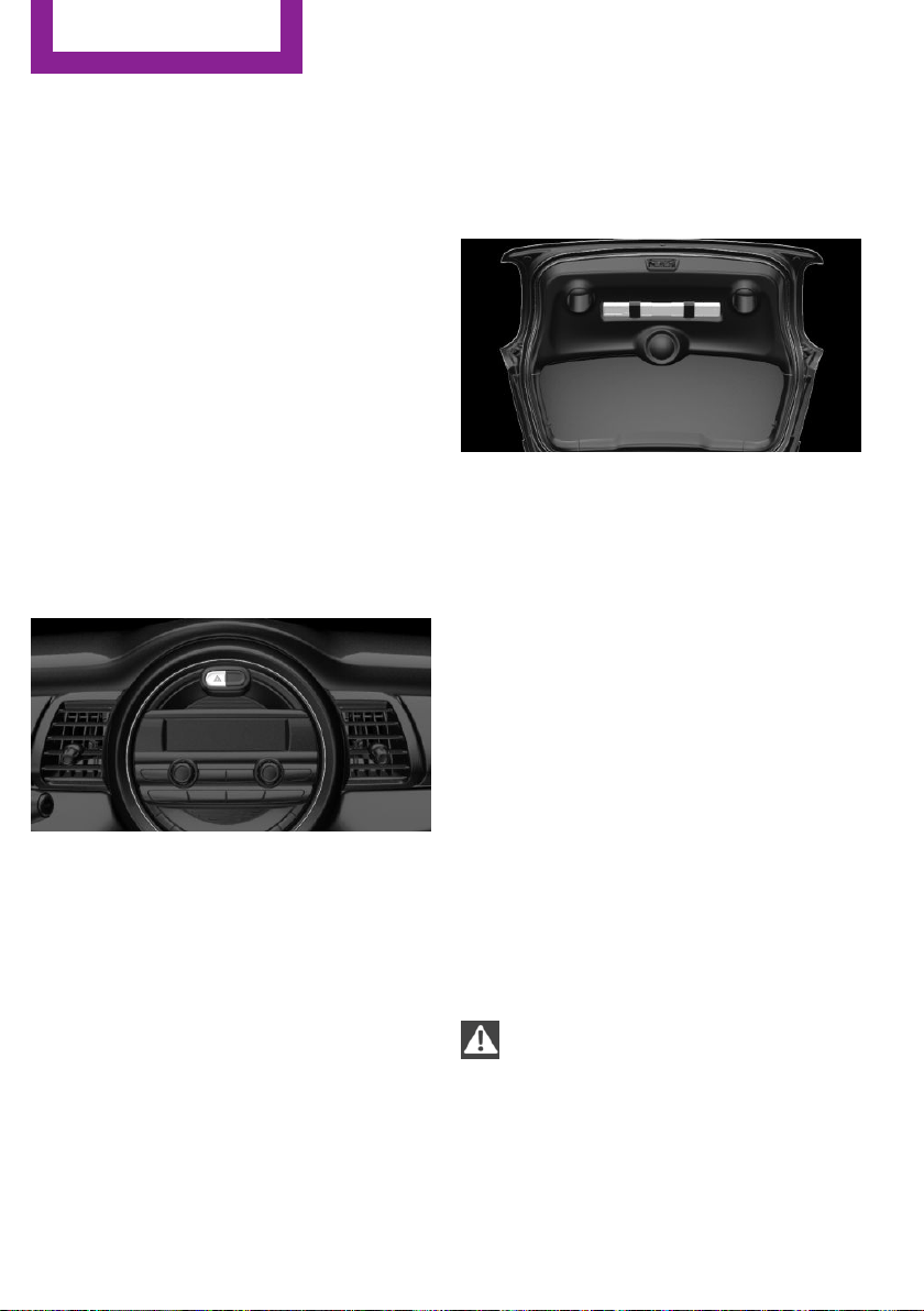
Breakdown assistance
Vehicle features and op‐
tions
This chapter describes all standard, country-
specific and optional features offered with the
series. It also describes features that are not
necessarily available in your car, e. g., due to
the selected options or country versions. This
also applies to safety-related functions and sys‐
tems. The respectively applicable country provi‐
sions must be observed when using the respec‐
tive features and systems.
Hazard warning flash‐
ers
The button is located above the radio.
Warning triangle
The warning triangle is located in the tailgate.
To remove, loosen the brackets.
First-aid kit
The first-aid kit is located in the trunk.
Some of the articles have a limited service life.
Check the expiration dates of the contents reg‐
ularly and replace any expired items promptly.
Jump-starting
General information
If the battery is discharged, the engine can be
started using the battery of another vehicle and
two jumper cables. Only use jumper cables with
fully insulated clamp handles.
Information
DANGER
Contact with live components can lead to
an electric shock. There is risk of injuries or
danger to life. Do not touch any components
that are under voltage.◀
To prevent personal injury or damage to both
vehicles, adhere strictly to the following proce‐
dure.
Seite 214
MOBILITY
Breakdown assistance
214
Online Edition for Part no. 01 40 2 963 307 - VI/15
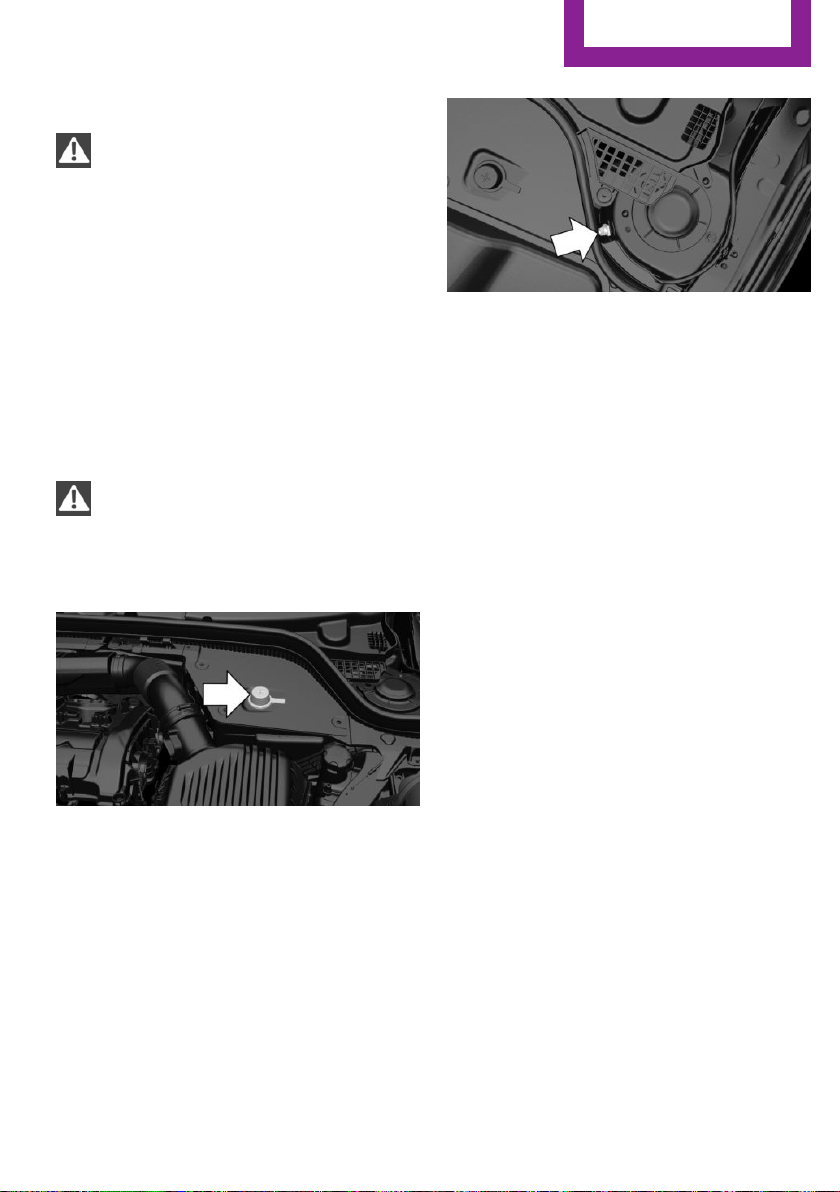
Preparation
CAUTION
In the case of body contact between the
two vehicles, a short circuit can occur during
jump-starting. There is risk of property damage.
Make sure that no body contact occurs.◀
1. Check whether the battery of the other ve‐
hicle has a voltage of 12 volts. This informa‐
tion can be found on the battery.
2. Switch off the engine of the assisting vehi‐
cle.
3. Switch off any electronic systems/power
consumers in both vehicles.
Starting aid terminals
WARNING
If the jumper cables are connected in the
incorrect order, sparks formation can occur.
There is risk of injuries. Pay attention to the cor‐
rect order during connection.◀
The so-called starting aid terminal in the engine
compartment acts as the battery's positive ter‐
minal.
Open the lid of the starting aid terminal.
The body ground acts as the negative terminal
of the battery.
Connecting the cables
1.
Pull off the lid of the starting aid terminal.
2. Attach one terminal clamp of the positive
jumper cable to the positive terminal of the
battery, or to the corresponding starting aid
terminal of the vehicle providing assistance.
3. Attach the terminal clamp on the other end
of the cable to the positive terminal of the
battery, or to the corresponding starting aid
terminal of the vehicle to be started.
4. Attach one terminal clamp of the negative
jumper cable to the negative terminal of
the battery, or to the corresponding engine
or body ground of assisting vehicle.
5. Attach the second terminal clamp to the
negative terminal of the battery, or to the
corresponding engine or body ground of
the vehicle to be started.
Starting the engine
Never use spray fluids to start the engine.
1.
Start the engine of the assisting vehicle and
let it run for several minutes at an increased
idle speed.
2. Start the engine of the vehicle that is to be
started in the usual way.
If the first starting attempt is not successful,
wait a few minutes before making another
attempt in order to allow the discharged
battery to recharge.
Seite 215
Breakdown assistance
MOBILITY
215
Online Edition for Part no. 01 40 2 963 307 - VI/15
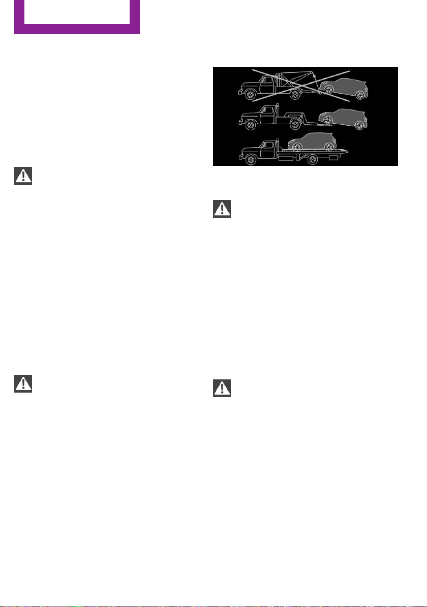
3. Let both engines run for several minutes.
4. Disconnect the jumper cables in the reverse
order.
Check the battery and recharge if needed.
Tow-starting and towing
Information
WARNING
Due to system limits, individual functions
can malfunction during tow-starting/towing
with the Intelligent Safety systems activated,
e.g. approach control warning with light brak‐
ing function. There is risk of an accident. Switch
all Intelligent Safety systems off prior to tow-
starting/towing.◀
Switching off Intelligent Safety systems, refer to
page 90.
Steptronic transmission: transporting
your vehicle
Information
Your vehicle must not be towed if the front
wheels are touching the ground.
CAUTION
The vehicle can be damaged when tow‐
ing the vehicle with a lifted rear axle. There is
risk of property damage. Have vehicle trans‐
ported only with lifted front axle or on a load‐
ing platform.◀
Tow truck
Have your vehicle transported with a tow truck
with a so-called lift bar or on a flat bed.
CAUTION
When lifting the vehicle by the tow fitting
or body and chassis parts; damage can occur
on vehicle parts. There is risk of property dam‐
age. Lift vehicle using suitable means.◀
Use tow fitting located in the front only for po‐
sitioning the vehicle.
Manual transmission
Observe before towing your vehicle
Gearshift lever in neutral position.
Towing
CAUTION
If manual unlocking of the parking brake
is not possible, the vehicle cannot be moved or
towed. There is risk of property damage. The
vehicle should only be transported on a loading
platform.◀
Information the following instructions:
▷ Make sure that the ignition is switched on;
otherwise, the low beams, tail lights, turn
signals, and wipers may be unavailable.
▷ Do not tow the vehicle with the rear axle
tilted, as the front wheels could turn.
▷ When the engine is stopped, there is no
power assist. Consequently, more force
Seite 216
MOBILITY
Breakdown assistance
216
Online Edition for Part no. 01 40 2 963 307 - VI/15
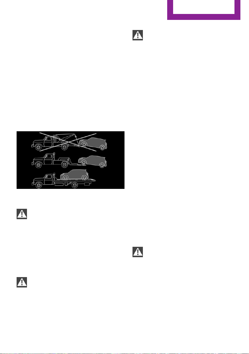
needs to be applied when braking and
steering.
▷ Larger steering wheel movements are re‐
quired.
▷ The towing vehicle must not be lighter than
the vehicle being towed; otherwise, it will
not be possible to control the vehicle's re‐
sponse.
▷ Do not exceed a towing speed of
30 mph/50 km/h.
▷ Do not exceed a towing distance of
30 miles/50 km.
Tow truck
Have your vehicle transported with a tow truck
with a so-called lift bar or on a flat bed.
CAUTION
When lifting the vehicle by the tow fitting
or body and chassis parts; damage can occur
on vehicle parts. There is risk of property dam‐
age. Lift vehicle using suitable means.◀
Towing other vehicles
Information
WARNING
If the approved gross vehicle weight of
the towing vehicle is lighter than the vehicle to
be towed, the tow fitting can tear off or it will
not be possible to control the vehicle's re‐
sponse. There is risk of an accident! Make sure
that the gross vehicle weight of the towing ve‐
hicle is heavier than the vehicle to be towed.◀
CAUTION
If the tow bar or tow rope is attached in‐
correctly, damage to other vehicle parts can oc‐
cur. There is risk of property damage. Correctly
attach the tow bar or tow rope to the tow fit‐
ting.◀
▷ Switch on the hazard warning system, de‐
pending on local regulations.
▷ If the electrical system has failed, clearly
identify the vehicle being towed by placing
a sign or a warning triangle in the rear win‐
dow.
Tow bar
The tow fittings used should be on the same
side on both vehicles.
Should it prove impossible to avoid mounting
the tow bar at an offset angle, please observe
the following:
▷ Maneuvering capability is limited going
around corners.
▷ The tow bar will generate lateral forces if it
is secured with an offset.
Tow rope
When starting to tow the vehicle, make sure
that the tow rope is taut.
To avoid jerking and the associated stresses on
the vehicle components when towing, always
use nylon ropes or nylon straps.
CAUTION
If the tow bar or tow rope is attached in‐
correctly, damage to other vehicle parts can oc‐
cur. There is risk of property damage. Correctly
attach the tow bar or tow rope to the tow fit‐
ting.◀
Seite 217
Breakdown assistance
MOBILITY
217
Online Edition for Part no. 01 40 2 963 307 - VI/15
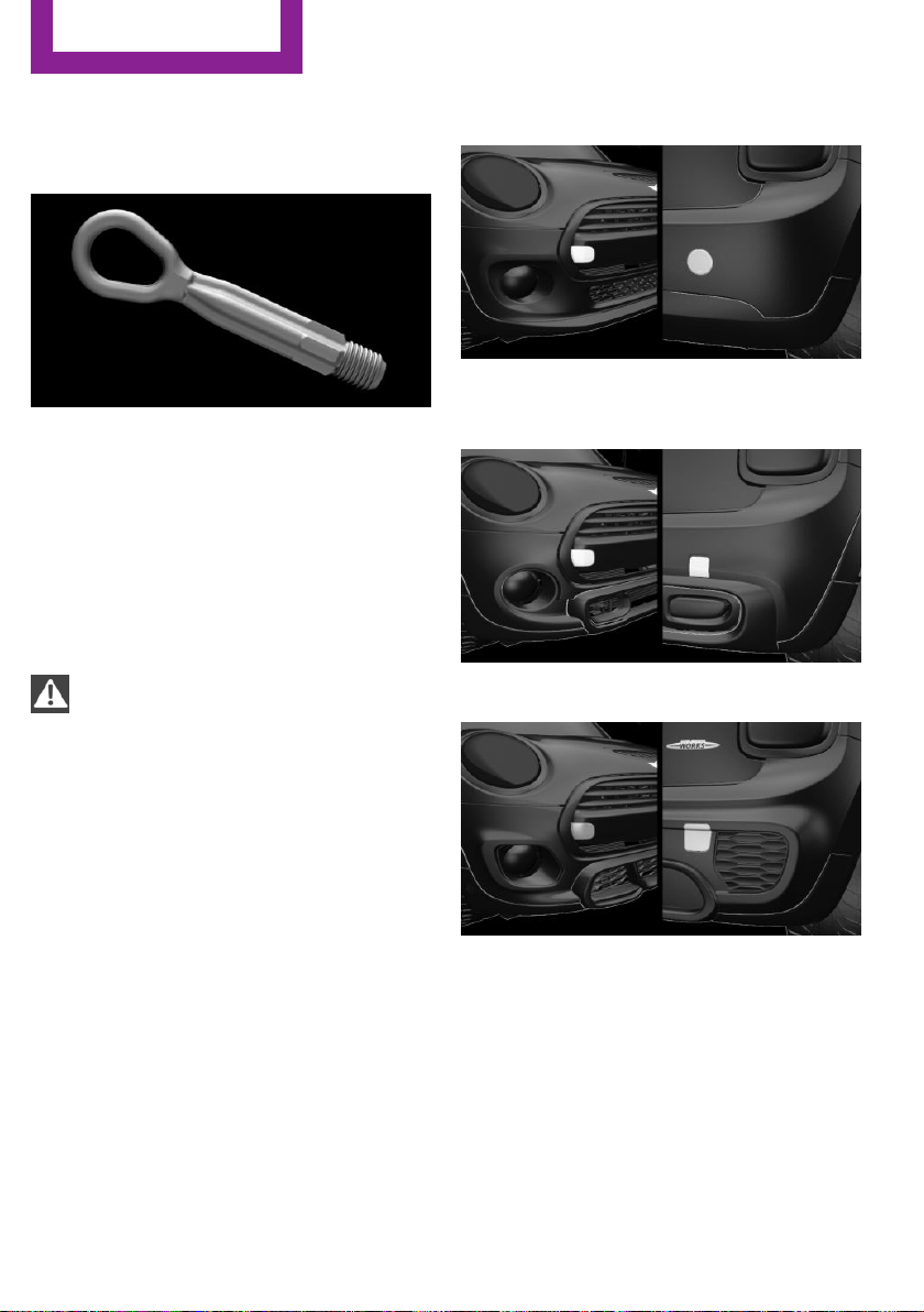
Tow fitting
General information
The screw-in tow fitting should always be car‐
ried in the vehicle.
The tow fitting can be screwed in at the front or
rear of the MINI.
The tow fitting and the onboard vehicle tool kit,
refer to page 202, are together in the cargo
area.
Information
CAUTION
If the tow fitting is not used as intended,
there can be damage to the vehicle or to the
tow fitting. There is risk of property damage.
Observe the notes on using the tow fitting.◀
Use of the tow fitting:
▷ Use only the tow fitting provided with the
vehicle and screw it all the way in.
▷ Use the tow fitting for towing on paved
roads only.
▷ Use tow fitting located in the front only for
positioning the vehicle.
▷ Avoid lateral loading of the tow fitting, e.g.,
do not lift the vehicle by the tow fitting.
Screw thread for tow fitting
COOPER/COOPER D
ONE/ONE D
COOPER S/COOPER SD
JOHN COOPER WORKS
Threaded holes for the tow fitting are located in
the front and rear of the vehicle on the right
side with respect to the direction of travel.
Push out the cover by pressing on the top edge.
Tow-starting
Steptronic transmission
Do not tow-start the vehicle.
Seite 218
MOBILITY
Breakdown assistance
218
Online Edition for Part no. 01 40 2 963 307 - VI/15

Tow-starting the engine is not possible due to
the Steptronic transmission.
Have the cause of the starting problems fixed.
Manual transmission
If possible, do not tow-start the vehicle but
start the engine by jump-starting, refer to
page 214. If the vehicle is equipped with a cat‐
alytic converter, only tow-start while the engine
is cold.
1. Switch on the hazard warning system and
comply with local regulations.
2. Ignition, refer to page 49, on.
3. Engage third gear.
4. Have the vehicle tow-started with the
clutch pedal pressed and slowly release the
pedal. After the engine starts, immediately
press on the clutch pedal again.
5. Stop at a suitable location, remove the tow
bar or rope, and switch off the hazard
warning system.
6. Have the vehicle checked.
Seite 219
Breakdown assistance
MOBILITY
219
Online Edition for Part no. 01 40 2 963 307 - VI/15

Care
Vehicle features and op‐
tions
This chapter describes all standard, country-
specific and optional features offered with the
series. It also describes features that are not
necessarily available in your car, e. g., due to
the selected options or country versions. This
also applies to safety-related functions and sys‐
tems. The respectively applicable country provi‐
sions must be observed when using the respec‐
tive features and systems.
Car washes
General information
Regularly remove foreign objects such as leaves
in the area below the windshield when the
hood is raised.
Wash your vehicle frequently, particularly in
winter. Intense soiling and road salt can dam‐
age the vehicle.
Steam jets or high-pressure washers
Information
CAUTION
When cleaning with high-pressure wash‐
ers, components can be damaged due to the
pressure or temperatures being too high. There
is risk of property damage. Maintain sufficient
distance and do not spray too long continu‐
ously. Follow the user's manual for the high-
pressure washer.◀
Distances and temperature
▷ Maximum temperature: 140 ℉/60 ℃.
▷ Minimum distance from sensors, cameras,
seals: 12 in/30 cm.
▷ Minimum distance from glass sunroof:
31.5 inches/80 cm.
Automatic car washes
Information
▷ Give preference to cloth car washes or
those that use soft brushes in order to
avoid paint damage.
▷ Make sure that the wheels and tires are not
damaged by the transport mechanisms.
▷ Fold in the exterior mirrors; otherwise, they
may be damaged, depending on the width
of the vehicle.
▷ Unscrew the rod antenna.
▷ Deactivate the rain sensor, refer to
page 56, to avoid unintentional wiper acti‐
vation.
▷ In some cases, an unintentional alarm can
be triggered by the interior motion sensor
of the alarm system. Follow the instructions
on avoiding an unintentional alarm, refer to
page 31.
CAUTION
Too high guide rails in car washes can
damage body parts. There is risk of property
damage. Avoid car washes with guide rails
higher than 4 in/10 cm.◀
Before driving into a car wash
In order to ensure that the vehicle can roll in a
car wash, take the following steps:
Manual transmission:
1.
Drive into the car wash.
2. Shift to neutral.
3. Switch the engine off.
4. Switch on the ignition.
Seite 220
MOBILITY
Care
220
Online Edition for Part no. 01 40 2 963 307 - VI/15

Steptronic transmission:
1. Drive into the car wash.
2. Engage selector lever position N.
3. Make sure that the parking brake is re‐
leased.
4. Press the Start/Stop button to switch off the
engine.
In this way, the ignition remains switched
on, and two Check-Control messages are
displayed.
A signal sounds when you leave the vehicle
while in selector lever position N.
The vehicle cannot be locked from the outside
when in selector lever position N. A signal is
sounded when an attempt is made to lock the
vehicle.
To start the engine with manual transmission:
1.
Press on the clutch pedal.
2. Press the Start/Stop button.
To start the engine with Steptronic transmis‐
sion:
1.
Depress the brake pedal.
2. Press the Start/Stop button.
Headlights
▷ Do not rub dry and do not use abrasive or
acidic cleansers.
▷ Soak areas that have been dirtied e. g.,
from insects, with shampoo and wash off
with water.
▷ Thaw ice with de-icing spray; do not use an
ice scraper.
After washing the vehicle
After washing the vehicle, apply the brakes
briefly to dry them; otherwise, braking action
can be reduced and corrosion of the brake
discs can occur.
Completely remove all residues on the win‐
dows, to minimize loss of visibility due to
smearing and to reduce wiper noises and wiper
blade wear.
Vehicle care
Car care products
The manufacturer of your vehicle recommends
using care and cleaning products from MINI.
WARNING
Cleansers can contain substances that are
dangerous and harmful to your health. There is
risk of injuries. When cleaning the interior, open
the doors or windows. Only use products in‐
tended for cleaning vehicles. Follow the instruc‐
tions on the container.◀
Vehicle paint
Regular care contributes to driving safety and
value retention. Environmental influences in
areas with elevated air pollution or natural con‐
taminants, such as tree resin or pollen can af‐
fect the vehicle's paintwork. Tailor the fre‐
quency and extent of your car care to these
influences.
Aggressive substances such as spilled fuel, oil,
grease or bird droppings must be removed im‐
mediately to prevent the finish from being al‐
tered or discolored.
Leather care
Remove dust from the leather often, using a
cloth or vacuum cleaner.
Otherwise, particles of dust and road grime
chafe in pores and folds, and lead to increased
wear and premature degradation of the leather
surface.
To guard against discoloration, such as from
clothing, provide leather care roughly every
two months.
Clean light-colored leather more frequently be‐
cause soiling on such surfaces is substantially
more visible.
Seite 221
Care
MOBILITY
221
Online Edition for Part no. 01 40 2 963 307 - VI/15

Use leather care products; otherwise, dirt and
grease will gradually break down the protective
layer of the leather surface.
Suitable care products are available from a
dealer’s service center or another qualified
service center or repair shop.
Upholstery material care
Vacuum regularly with a vacuum cleaner.
If upholstery is very dirty, e.g., with beverage
stains, use a soft sponge or microfiber cloth
with a suitable interior cleaner.
Clean the upholstery down to the seams using
large sweeping motions. Avoid rubbing the ma‐
terial vigorously.
CAUTION
Open Velcro® fasteners on articles of
clothing can damage the seat covers. There is
risk of property damage. Ensure that any Vel‐
cro® fasteners are closed.◀
Caring for special components
Light-alloy wheels
When cleaning the vehicle, use only neutral
wheel cleaners having a pH value from 5 to 9.
Do not use abrasive cleaning agents or steam
jets above 140 ℉/60 ℃. Follow the manufac‐
turer's instructions.
Aggressive, acidic or alkaline cleaning agents
can destroy the protective layer of adjacent
components, such as the brake disk.
Chrome surfaces
Carefully clean components such as the radia‐
tor grille or door handles with an ample supply
of water, possibly with shampoo added, partic‐
ularly when they have been exposed to road
salt.
Rubber components
Environmental influences can cause surface
soiling of rubber parts and a loss of gloss. For
cleaning, use only water and suitable care
products, the manufacturer of your vehicle rec‐
ommends original MINI care products.
Treat especially worn rubber parts with rubber
care agents at regular intervals. When cleaning
rubber seals, do not use any silicon-containing
car care products in order to avoid damage or
noises.
Fine wood parts
Clean fine wood facing and fine wood compo‐
nents only with a moist rag. Then dry with a
soft cloth.
Plastic components
These include:
▷ Imitation leather surfaces.
▷ Roofliner.
▷ Lamp lenses.
▷ Instrument cluster cover.
▷ Matt black spray-coated components.
▷ Painted parts in the interior.
Clean with a microfiber cloth.
Dampen cloth lightly with water.
Do not soak the roofliner.
CAUTION
Cleansers that contain alcohol or solvents,
such as lacquer thinners, heavy-duty grease re‐
movers, fuel, or such, can damage plastic parts.
There is risk of property damage. Clean with a
microfiber cloth. Dampen cloth lightly with wa‐
ter.◀
Safety belts
Dirty belt straps impede the reeling action and
thus have a negative impact on safety.
WARNING
Chemical cleansers can destroy the safety
belt webbing. Missing protective effect of the
safety belts. There is risk of injuries or danger to
Seite 222
MOBILITY
Care
222
Online Edition for Part no. 01 40 2 963 307 - VI/15

life. Use only a mild soapy solution for cleaning
the safety belts.◀
Use only a mild soapy solution, with the safety
belts clipped into their buckles.
Do not allow the switchs to retract the safety
belts until they are dry.
Carpets and floor mats
WARNING
Objects in the driver's floor area can limit
the pedal distance or block a depressed pedal.
There is risk of an accident. Stow objects in the
vehicle such that they are secured and cannot
enter into the driver's floor area. Use floor mats
that are suitable for the vehicle and can be
safely attached to the floor. Do not use loose
floor mats and do not layer several floor mats.
Make sure that there is sufficient clearance for
the pedals. Ensure that the floor mats are se‐
curely fastened again after they were removed,
e.g. for cleaning.◀
Floor mats can be removed from the car's inte‐
rior for cleaning.
If the floor carpets are very dirty, clean with a
microfiber cloth and water or a textile cleaner.
To prevent matting of the carpet, rub back and
forth in the direction of travel only.
Sensor/camera lenses
To clean sensors and camera lenses, use a cloth
moistened with a small amount of glass deter‐
gent.
Displays/Screens
CAUTION
Chemical cleansers, moisture or fluids of
any kind can damage the surface of displays
and screens. There is risk of property damage.
Clean with a clean, antistatic microfiber cloth.◀
CAUTION
The surface of displays can be damaged
with improper cleaning. There is risk of prop‐
erty damage. Avoid pressure that is too high
and do not use any scratching materials.◀
Clean with a clean, antistatic microfiber cloth.
Long-term
When the vehicle is shut down for longer than
three months, special measures must be taken.
Further information is available from a dealer’s
service center or another qualified service cen‐
ter or repair shop.
Seite 223
Care
MOBILITY
223
Online Edition for Part no. 01 40 2 963 307 - VI/15

FIND ME.
Online Edition for Part no. 01 40 2 963 307 - VI/15

AT A GLANCE
CONTROLS
DRIVING TIPS
ENTERTAINMENT
COMMUNICATION
MOBILITY
REFERENCE
Online Edition for Part no. 01 40 2 963 307 - VI/15

Technical data
Vehicle features and op‐
tions
This chapter describes all standard, country-
specific and optional features offered with the
series. It also describes features that are not
necessarily available in your car, e. g., due to
the selected options or country versions. This
also applies to safety-related functions and sys‐
tems. The respectively applicable country provi‐
sions must be observed when using the respec‐
tive features and systems.
Information
The technical data and specifications in this
Owner's Manual are used as guidance values.
The vehicle-specific data can deviate from this,
for example, due to the selected special equip‐
ment, country version or country-specific
measurement method. Detailed values can be
found in the approval documents, on labels on
the vehicle or can be obtained from a dealer’s
service center or another qualified service cen‐
ter or repair shop.
The information in the vehicle documents al‐
ways has priority.
Dimensions
The dimensions can vary depending on the
model version, equipment or country-specific
measurement method.
The specified heights do not take into account
attached parts, for example, a roof antenna,
roof racks or spoiler. The heights can deviate,
for example, due to the selected special equip‐
ment, tires, load and chassis version.
Seite 226
REFERENCE
Technical data
226
Online Edition for Part no. 01 40 2 963 307 - VI/15
MINI 3-door
Width with mirrors inches/mm 76.1/1,932
Width without mirrors inches/mm 68.0/1,727
Height inches/mm 55.7/1,414
Length
Cooper inches/mm 151.1/3,837
Cooper S inches/mm 151.9/3,858
John Cooper Works inches/mm
Wheelbase inches/mm 98.2/2,495
Smallest turning radius diam. ft/m 35.4/10.8
152.5/3,874

Seite 227
Technical data
REFERENCE
227
Online Edition for Part no. 01 40 2 963 307 - VI/15
MINI 5-door
Width with mirrors inches/mm 76.1/1,932
Width without mirrors inches/mm 68.0/1,727
Height inches/mm 56.1/1,425
Length
Cooper inches/mm 157.4/3,998
Cooper S inches/mm 158.0/4,013
Wheelbase inches/mm 101.1/2,567
Smallest turning radius diam. ft/m 36.2/11.02
Weights
The values preceding the slash apply to vehicles
with manual transmission; the values following
the slash apply to vehicles with Steptronic
transmission.
MINI Cooper, 3-door
Approved gross vehicle weight lbs
kg
3,455/3,520
1,567/1,597
Load lbs
kg
680
308
Approved front axle load lbs
kg
1,920/1,990
871/903
Approved rear axle load lbs
kg
1,665
755
Approved roof load capacity lbs
kg
132
60
Cargo area capacity cu ft
Liters
8.7–34.0
211–731

Seite 228
REFERENCE
Technical data
228
Online Edition for Part no. 01 40 2 963 307 - VI/15
MINI Cooper, 5-door
Approved gross vehicle weight lbs
kg
3,680/3,750
1,669/1,701
Load lbs
kg
775
352
Approved front axle load lbs
kg
1,995/2,065
905/937
Approved rear axle load lbs
kg
1,840
835
Approved roof load capacity lbs
kg
165
75
Cargo area capacity cu ft
Liters
13.1–40.7
278–941
MINI Cooper S, 3-door
Approved gross vehicle weight lbs
kg
3,620/3,650
1,642/1,656
Load lbs
kg
775/770
352/349
Approved front axle load lbs
kg
2,025/2,060
919/934
Approved rear axle load lbs
kg
1,690
767
Approved roof load capacity lbs
kg
132
60
Cargo area capacity cu ft
Liters
8.7–34.0
211–731

Seite 229
Technical data
REFERENCE
229
Online Edition for Part no. 01 40 2 963 307 - VI/15
MINI Cooper S, 5-door
Approved gross vehicle weight lbs
kg
3,860/3,900
1,751/1,769
Load lbs
kg
885/885
401/401
Approved front axle load lbs
kg
2,085/2,125
946/964
Approved rear axle load lbs
kg
1,880
853
Approved roof load capacity lbs
kg
165
75
Cargo area capacity cu ft
Liters
13.1–40.7
278–941
MINI John Cooper Works, 3-door
Approved gross vehicle weight lbs
kg
Load lbs
kg
Approved front axle load lbs
kg
Approved rear axle load lbs
kg
Approved roof load capacity lbs
kg
Cargo area capacity cu ft
Liters
8.7–34.0
246–963
3,720/3,765
1,687/1,708
775
352
2,065/2,105
937/955
1,725
782
132
60


Appendix
Any updates to the Owner's Manual of the ve‐
hicle are listed here.
Seite 231
Appendix
REFERENCE
231
Online Edition for Part no. 01 40 2 963 307 - VI/15
Active pedestrian protec‐
tion system
Opposite to the description in this Owner's
Manual, the active pedestrian protection sys‐
tem is only deployed at speeds between ap‐
prox. 30 km/h/approx. 18 mph and 55 km/h/
34 mph.

Seite 232
REFERENCE
232
Online Edition for Part no. 01 40 2 963 307 - VI/15

Seite 233
REFERENCE
233
Online Edition for Part no. 01 40 2 963 307 - VI/15

Seite 234
REFERENCE
234
Online Edition for Part no. 01 40 2 963 307 - VI/15
License Texts and Certifications
Bluetooth
Brazil
Europe
Register model name: UK001
Product code: MRBE307A
Hrvatski
Ovim, Alpine, izjavljuje da ovaj tip RADIO UKL
zadovoljava bitne zahtjeve i ostale važece
odrednice, a sukladno Smjernici 1999/5/EC.
Čeština
Alpine tímto prohlašuje, že tento RADIO UKL je
ve shodě se základními požadavky a dalšími
príslušnými ustanoveními smernice 1999/5/ES.
Dansk
Undertegnede Alpine erklærer herved, at
følgende udstyr RADIO UKL overholder de væ‐
sentlige krav og øvrige relevante krav i direktiv
1999/5/EF.
Deutsch
Hiermit erklärt Alpine, dass sich das Gerät
RADIO UKL in Übereinstimmung mit den
grundlegenden Anforderungen und den übri‐
gen einschlägigen Bestimmungen der Richtlinie
1999/5/EG befindet.
Eesti
Käesolevaga kinnitab Alpine seadme RADIO
UKL vastavust direktiivi 1999/5/EÜ põhinõue‐
tele ja nimetatud direktiivist tulenevatele teis‐
tele asjakohastele sätetele.
English
Hereby, Alpine, declares that this RADIO UKL is
in compliance with the essential requirements
and other relevant provisions of Directive
1999/5/EC.
Español
Por medio de la presente Alpine declara que el
RADIO UKL cumple con los requisitos esen‐
ciales y cualesquiera otras disposiciones aplica‐
bles o exigibles de la Directiva 1999/5/CE.
Ελληνικά
ΜΕ ΤΗΝ ΠΑΡΟΥΣΑ Alpine ∆ΗΛΩΝΕΙ ΟΤΙ RADIO
UKL ΣΥΜΜΟΡΦΩΝΕΤΑΙ ΠΡΟΣ ΤΙΣ ΟΥΣΙΩ∆ΕΙΣ
ΑΠΑΙΤΗΣΕΙΣ ΚΑΙ ΤΙΣ ΛΟΙΠΕΣ ΣΧΕΤΙΚΕΣ
∆ΙΑΤΑΞΕΙΣ ΤΗΣ Ο∆ΗΓΙΑΣ 1999/5/ΕΚ.
Français
Par la présente Alpine déclare que l'appareil
RADIO UKL est conforme aux exigences essen‐
tielles et aux autres dispositions pertinentes de
la directive 1999/5/CE.
Seite 235
License Texts and Certifications
REFERENCE
235
Online Edition for Part no. 01 40 2 963 307 - VI/15

Italiano
Con la presente Alpine dichiara che questo
RADIO UKL è conforme ai requisiti essenziali ed
alle altre disposizioni pertinenti stabilite dalla
direttiva 1999/5/CE.
Latviešu
Ar šo Alpine deklarē, ka RADIO UKL atbilst Dir‐
ektīvas 1999/5/EK būtiskajām prasībām un cit‐
iem ar to saistītajiem noteikumiem.
Lietuvių
Šiuo Alpine deklaruoja, kad šis RADIO UKL ati‐
tinka esminius reikalavimus ir kitas 1999/5/EB
Direktyvos nuostatas.
Nederlands
Hierbij verklaart Alpine dat het toestel RADIO
UKL in overeen-stemming is met de essentiële
eisen en de andere relevante bepalingen van
richtlijn 1999/5/EG.
Malti
Hawnhekk, Alpine, jiddikjara li dan RADIO UKL
jikkonforma mal-ħtigijiet essenzjali u ma prov‐
vedimenti oħrajn relevanti li hemm fid-Dirret‐
tiva 1999/5/EC.
Magyar
Alulírott, Alpine nyilatkozom, hogy a RADIO
UKL megfelel a vonatkozó alapvető követelmé‐
nyeknek és az 1999/5/EC irányelv egyéb előírá‐
sainak.
Polski
Niniejszym Alpine oświadcza, że RADIO UKL
jest zgodny z zasadniczymi wymogami oraz
pozostałymi stosownymi postanowieniami Dyr‐
ektywy 1999/5/EC.
Português
Alpine declara que este RADIO UKL está con‐
forme com os requisitos essenciais e outras dis‐
posições da Directiva 1999/5/CE.
Slovensko
Alpine izjavlja, da je ta RADIO UKL v skladu z
bistvenimi zahtevami in ostalimi relevantnimi
določili direktive 1999/5/ES.
Slovensky
Alpine týmto vyhlasuje, že RADIO UKL spĺňa zá‐
kladné požiadavky a všetky príslušné ustanove‐
nia Smernice 1999/5/ES.
Suomi
Alpine vakuuttaa täten että RADIO UKL tyyppi‐
nen laite on direktiivin 1999/5/EY oleellisten
vaatimusten ja sitä koskevien direktiivin mui‐
den ehtojen mukainen.
Svenska
Härmed intygar Alpine att denna RADIO UKL
står I överens-stämmelse med de väsentliga
egenskapskrav och övriga relevanta bestäm‐
melser som fram-går av direktiv 1999/5/EG.
Íslenska
Hér með lýsir Alpine yfir því að RADIO UKL er í
samræmi við grunnkröfur og aðrar kröfur, sem
gerðar eru í tilskipun 1999/5/EC.
Norsk
Alpine erklærer herved at utstyret RADIO UKL
er i samsvar med de grunnleggende krav og
øvrige relevante krav i direktiv 1999/5/EF.
Ukraine
Seite 236
REFERENCE
License Texts and Certifications
236
Online Edition for Part no. 01 40 2 963 307 - VI/15

Taiwan
USA (FCC) and Canada (IC)
Register model name: UK002
Product code: MRBE309A
FCC CAUTION
Changes or modifications not expressly ap‐
proved by the party responsible for compliance
could void the user’s authority to operate the
equipment.
This device complies with Part 15 of FCC Rules
and Industry Canada licence-exempt RSS stand‐
ard(s). Operation is subject to the following two
conditions: (1) this device may not cause inter‐
ference, and (2) this device must accept any in‐
terference, including interference that may
cause undesired operation of this device.
Le présent appareil est conforme aux la partie
15 des règles de la FCC et CNR d'Industrie Can‐
ada applicables aux appareils radio exempts de
licence. L'exploitation est autorisée aux deux
conditions suivantes : (1) l'appareil ne doit pas
produire de brouillage, et (2) l'utilisateur de
l'appareil doit accepter tout brouillage radioé‐
lectrique subi, même si le brouillage est suscep‐
tible d'en compromettre le fonctionnement.
This equipment complies with FCC/IC radiation
exposure limits set forth for an uncontrolled en‐
vironment and meets the FCC radio frequency
(RF) Exposure Guidelines in Supplement C to
OET65 and RSS-102 of the IC radio frequency
(RF) Exposure rules. This equipment has very
low levels of RF energy that it deemed to com‐
ply without maximum permissive exposure
evaluation (MPE). But it is desirable that it
should be installed and operated keeping the
radiator at least 20cm or more away from per‐
son’s body (excluding extremities: hands,
wrists, feet and ankles).
Cet équipement est conforme aux limites d’ex‐
position aux rayonnements énoncées pour un
environnement non contrôlé et respecte les rè‐
gles les radioélectriques (RF) de la FCC lignes di‐
rectrices d'exposition dans le Supplément C à
OET65 et d’exposition aux fréquences radioé‐
lectriques (RF) CNR-102 de l’IC. Cet équipement
émet une énergie RF très faible qui est consid‐
érée conforme sans évaluation de l’exposition
maximale autorisée. Cependant, cet équipe‐
ment doit être installé et utilisé en gardant une
distance de 20 cm ou plus entre le dispositif
rayonnant et le corps (à l’exception des ex‐
trémités : mains, poignets, pieds et chevilles).
Tire Pressure Monitoring
System
Canada
IC: 7812D-S180056
Operation is subject to the following two condi‐
tions:
(1) this device may not cause harmful interfer‐
ence, and
(2) this device must accept any interference re‐
ceived, including interference that may cause
undesired operation.
USA
FCC ID: KR5S180052056
This device complies with Part 15 of the FCC
Rules. Operation is subject to the following two
conditions:
(1) this device may not cause harmful interfer‐
ence, and
(2) this device must accept any interference re‐
ceived, including interference that may cause
undesired operation.
Seite 237
License Texts and Certifications
REFERENCE
237
Online Edition for Part no. 01 40 2 963 307 - VI/15

South Korea
Continental S180052056
KCC-CRM-TAL-S180052056
Europe
Declaration of Conformity in accordance with
Directive 1999/5/EC (R&TTE Directive)
Manufacturer: Continental Automotive GmbH
Product type designation: S180052056
Intended use: Tire pressure monitoring system
The product mentioned above complies with
the essential requirements and other relevant
provisions of Directive 1999/5/EC, when used
for its intended purpose:
Health and safety pursuant to Art. 3(1)(a):
Applied standard(s):
EN 60950–1:2006 + A11:2009 + A1:2010 +
A12:2011
EN 62479:2010
Electromagnetic compatibility pursuant to Art.
3(1)(b):
Applied standard(s):
EN 301 489–1 V1.8.1 (2008–04)
EN 301 489–3 V1.4.1 (2002–08)
Efficient use of spectrum pursuant to Art. 3(2):
Applied standard(s):
EN 300 220–1 V2.3.1 (2010–02)
EN 300 220–2 V2.3.1 (2010–02)
The following marking applies to the above
mentioned product:
Hrvatski
Ovim, Continental Automotive GmbH, izjavljuje
da ovaj tip TPMS zadovoljava bitne zahtjeve i
ostale važece odrednice, a sukladno Smjernici
1999/5/EC.
Čeština
Continental Automotive GmbH tímto prohla‐
šuje, že tento TPMS je ve shodě se základními
požadavky a dalšími príslušnými ustanoveními
smernice 1999/5/ES.
Dansk
Undertegnede Continental Automotive GmbH
erklærer herved, at følgende udstyr TPMS over‐
holder de væsentlige krav og øvrige relevante
krav i direktiv 1999/5/EF.
Deutsch
Hiermit erklärt Continental Automotive GmbH,
dass sich das Gerät TPMS in Übereinstimmung
mit den grundlegenden Anforderungen und
den übrigen einschlägigen Bestimmungen der
Richtlinie 1999/5/EG befindet.
Eesti
Käesolevaga kinnitab Continental Automotive
GmbH seadme TPMS vastavust direktiivi
1999/5/EÜ põhinõuetele ja nimetatud direktiiv‐
ist tulenevatele teistele asjakohastele sätetele.
English
Hereby, Continental Automotive GmbH, de‐
clares that this TPMS is in compliance with the
Seite 238
REFERENCE
License Texts and Certifications
238
Online Edition for Part no. 01 40 2 963 307 - VI/15

essential requirements and other rele-vant pro‐
visions of Directive 1999/5/EC.
Español
Por medio de la presente Continental Automo‐
tive GmbH declara que el TPMS cumple con los
requisitos esenciales y cuales-quiera otras dis‐
posiciones aplicables o exigi-bles de la Direc‐
tiva 1999/5/CE.
Ελληνικά
ΜΕ ΤΗΝ ΠΑΡΟΥΣΑ Continental Automotive
GmbH ∆ΗΛΩΝΕΙ ΟΤΙ TPMS ΣΥΜΜΟΡΦΩΝΕΤΑΙ
ΠΡΟΣ ΤΙΣ ΟΥΣΙΩ∆ΕΙΣ ΑΠΑΙΤΗΣΕΙΣ ΚΑΙ ΤΙΣ
ΛΟΙΠΕΣ ΣΧΕΤΙΚΕΣ ∆ΙΑΤΑΞΕΙΣ ΤΗΣ Ο∆ΗΓΙΑΣ
1999/5/ΕΚ.
Français
Par la présente Continental Automotive GmbH
déclare que l'appareil TPMS est conforme aux
exigences essentielles et aux autres disposi‐
tions pertinentes de la directive 1999/5/CE.
Italiano
Con la presente Continental Automotive GmbH
dichiara che questo TPMS è conforme ai requi‐
siti essenziali ed alle altre disposizioni perti‐
nenti stabilite dalla direttiva 1999/5/CE.
Latviešu
Ar šo Continental Automotive GmbH deklarē,
ka TPMS atbilst Direktīvas 1999/5/EK būtiska‐
jām prasībām un citiem ar to saistītajiem notei‐
kumiem.
Lietuvių
Šiuo Continental Automotive GmbH deklaruoja,
kad šis TPMS atitinka esminius reikalavimus ir
kitas 1999/5/EB Direktyvos nuostatas.
Nederlands
Hierbij verklaart Continental Automotive GmbH
dat het toestel TPMS in overeen-stemming is
met de essentiële eisen en de andere relevante
bepalingen van richtlijn 1999/5/EG.
Malti
Hawnhekk, Continental Automotive GmbH, jid‐
dikjara li dan TPMS jikkonforma mal-ħtigijiet es‐
senzjali u ma provvedimenti oħrajn relevanti li
hemm fid- Dirrettiva 1999/5/EC.
Magyar
Alulírott, Continental Automotive GmbH nyilat‐
kozom, hogy a TPMS megfelel a vonatkozó
alapvető követelményeknek és az 1999/5/EC
irányelv egyéb előírásainak.
Polski
Niniejszym Continental Automotive GmbH oś‐
wiadcza, że TPMS jest zgodny z zasadniczymi
wymogami oraz pozostałymi stosownymi post‐
anowieniami Dyrektywy 1999/5/EC.
Português
Continental Automotive GmbH declara que
este TPMS está conforme com os requisitos es‐
senciais e outras disposições da Directiva
1999/5/CE.
Slovensko
Continental Automotive GmbH izjavlja, da je ta
TPMS v skladu z bistvenimi zahtevami in osta‐
limi relevantnimi določili direktive 1999/5/ES.
Slovensky
Continental Automotive GmbH týmto vyhlasuje,
že TPMS spĺňa základné požiadavky a všetky
príslušné ustanovenia Smernice 1999/5/ES.
Suomi
Continental Automotive GmbH vakuuttaa täten
että TPMS tyyppinen laite on direktiivin
1999/5/EY oleellisten vaatimusten ja sitä kos‐
kevien direktiivin muiden ehtojen mukainen.
Seite 239
License Texts and Certifications
REFERENCE
239
Online Edition for Part no. 01 40 2 963 307 - VI/15

Svenska
Härmed intygar Continental Automotive GmbH
att denna TPMS står I överens-stämmelse med
de väsentliga egenskapskrav och övriga rele‐
vanta bestämmelser som fram-går av direktiv
1999/5/EG.
Íslenska
Hér með lýsir Continental Automotive GmbH
yfir því að TPMS er í samræmi við grunnkröfur
og aðrar kröfur, sem gerðar eru í tilskipun
1999/5/EC.
Norsk
Continental Automotive GmbH erklærer herved
at utstyret TPMS er i samsvar med de grunnleg‐
gende krav og øvrige relevante krav i direktiv
1999/5/EF.
Israel
A. The use of this product does not need a
wireless operation license.
B. The product does not include an RF disturb‐
ance protection, and should not disturb other
licensed products.
C. It is forbidden to replace the antenna or to
make any change in this product.
Australia/New Zealand
Russia
C-DE-ML05.H01232
South Africa
China
In accordance with the provisions on the Radio
Regulations of the people's Republic of China,
the radio transmission equipment, after exami‐
nation, conforms to the provisions with its
CMIIT ID: 2013DJ7376
Information regarding
Open Source Software Li‐
censes
The “IwIP – A Lightweight TCP/IP stack” in‐
cluded in some products is licensed under the
“BSD licence”. A copy of that license in the Eng‐
lish original version with a copyright notice, a
disclaimer of warranty, and an exclusion of lia‐
bility is included below. Copyright (c)
2001-2004 Swedish Institute of Computer Sci‐
ence. All rights reserved. Redistribution and use
in source and binary forms, with or without
modification, are permitted provided that the
following conditions are met: 1. Redistributions
of source code must retain the above copyright
notice, this list of conditions and the following
disclaimer. 2. Redistributions in binary form
must reproduce the above copyright notice,
this list of conditions and the following dis‐
claimer in the documentation and/or other ma‐
terials provided with the distribution. 3. The
name of the author may not be used to en‐
dorse or promote products derived from this
software without specific prior written permis‐
sion. THIS SOFTWARE IS PROVIDED BY THE AU‐
Seite 240
REFERENCE
License Texts and Certifications
240
Online Edition for Part no. 01 40 2 963 307 - VI/15

THOR ``AS IS`` AND ANY EXPRESS OR IMPLIED
WARRANTIES, INCLUDING, BUT NOT LIMITED
TO, THE IMPLIED WARRANTIES OF MERCHANT‐
ABILITY AND FITNESS FOR A PARTICULAR PUR‐
POSE ARE DISCLAIMED. IN NO EVENT SHALL
THE AUTHOR BE LIABLE FOR ANY DIRECT, INDI‐
RECT, INCIDENTAL, SPECIAL, EXEMPLARY, OR
CONSEQUENTIAL DAMAGES (INCLUDING, BUT
NOT LIMITED TO, PROCUREMENT OF SUBSTI‐
TUTE GOODS OR SERVICES; LOSS OF USE, DATA,
OR PROFITS; OR BUSINESS INTERRUPTION)
HOWEVER CAUSED AND ON ANY THEORY OF
LIABILITY, WHETHER IN CONTRACT, STRICT LIA‐
BILITY, OR TORT (INCLUDING NEGLIGENCE OR
OTHERWISE) ARISING IN ANY WAY OUT OF THE
USE OF THIS SOFTWARE, EVEN IF ADVISED OF
THE POSSIBILITY OF SUCH DAMAGE.
Seite 241
License Texts and Certifications
REFERENCE
241
Online Edition for Part no. 01 40 2 963 307 - VI/15

Everything from A to Z
Index
A
ABS, Antilock Brake Sys‐
tem 97
Acceleration Assistant, refer to
Launch Control 61
ACC, see camera-based cruise
control 101
Activated-charcoal filter 120
Active Cruise Control, see
camera-based cruise con‐
trol 101
Additives, oil 197
Adjustments, seats/head re‐
straints 36
Adjustments, steering
wheel 44
After washing vehicle 221
Airbags 81
Airbags, indicator/warning
light 82
Air circulation, refer to Recir‐
culated-air mode 119
Air circulation, see Recircu‐
lated-air mode 116
Air conditioner 115
Air, dehumidifying, see Cool‐
ing function 116, 118
Air distribution,
manual 116, 119
Air flow, air conditioner 116
Air flow, automatic climate
control 119
Air pressure, tires 178
Air vents, refer to Ventila‐
tion 120
Alarm system 30
Alarm triggering 30
Alarm, unintentional 31
All around the center con‐
sole 16
All around the roofliner 17
All around the steering
wheel 14
All-season tires, see Winter
tires 187
Alternating-code hand-held
transmitter 122
Alternative oil types 197
Antifreeze, washer fluid 57
Antilock Brake System,
ABS 97
Anti-slip control, see DSC 97
Apple iPod/iPhone 157
Approved axle load 227
Ash tray 125
Assistance when driving
off 100
Assist system, see Intelligent
Safety 90
AUTO intensity 118
Automatic car wash 220
Automatic climate con‐
trol 117
Automatic Curb Monitor 42
Automatic deactivation, Front-
seat passenger airbags 83
Automatic headlight con‐
trol 77
Automatic locking 30
Automatic recirculated-air
control 119
Automatic transmission with
Steptronic 58
AUTO program, automatic cli‐
mate control 118
AUTO program, intensity 118
Auto Start/Stop function 51
AUX-IN port 156
Average fuel consumption 71
Average speed 72
Axle loads, weights 227
B
Backrest curvature, refer to
Lumbar support 37
Balance 150
Band-aids, see First-aid
kit 214
Bar for tow-starting/
towing 217
Bass 150
Battery replacement, vehicle
battery 212
Battery, vehicle 212
Belts, safety belts 38
Beverage holder, cu‐
pholder 130
Bluetooth, refer to Hands-free
system 164
Bonus range, GREEN
mode 144
Bottle holder, see Cu‐
pholder 130
Brake assistant 97
Brake discs, break-in 136
Brake pads, break-in 136
Braking, hints 137
Breakdown assistance 214
Break-in 136
Bug light 204
Bulb replacement 203
Bulb replacement, front 204
Bulb replacement, rear 206
Bulb replacement, side 209
Bulbs and lights 203
Button, Start/Stop 49
Bypassing, see Jump-start‐
ing 214
Seite 242
REFERENCE
Everything from A to Z
242
Online Edition for Part no. 01 40 2 963 307 - VI/15

C
California Proposition 65
Warning 7
Camera-based cruise con‐
trol 101
Camera lenses, care 223
Can holder, see Cu‐
pholder 130
Car battery 212
Car care products 221
Care, displays 223
Care, vehicle 221
Cargo area 126
Cargo area, adapting size 131
Cargo area, enlarging 127
Cargo area lid 27
Cargo area, storage compart‐
ments 131
Cargo cover 126
Cargo, securing 140
Cargo straps, securing
cargo 140
Car key, see Remote con‐
trol 22
Carpet, care 223
Car wash 220
Catalytic converter, see Hot
exhaust system 137
CBS Condition Based Serv‐
ice 200
Center armrest 130
Center console 16
Central instrument cluster,
LED ring 73
Central locking system 26
Changes, technical, refer to
Own Safety 7
Changing parts 202
Changing the station 152
Changing wheels 210
Changing wheels/tires 186
Chassis number, see vehicle
identification number 9
Check Control 63
Checking the oil level elec‐
tronically 195
Children, seating position 45
Children, transporting
safely 45
Child restraint fixing sys‐
tem 45
Child restraint fixing system
LATCH 47
Child restraint fixing systems,
mounting 46
Child safety locks 48
Child seat, mounting 46
Child seats 45
Chrome parts, care 222
Chrono package, cockpit 74
Cigarette lighter 125
Cleaning, displays 223
Climate control 115, 117
Clock 67
Closing/opening via door
lock 26
Closing/opening with remote
control 24
Clothes hooks 131
Coasting 145
Coasting with engine decou‐
pled, coasting 145
Coasting with idling en‐
gine 145
Combination switch, see Turn
signals 54
Combi switch, see wiper sys‐
tem 55
Comfort Access 28
Compartments in the
doors 130
Compass 123
Compressor 188
Condensation on win‐
dows 119
Condensation under the vehi‐
cle 138
Condition Based Service
CBS 200
Confirmation signal 30
Control systems, driving stabil‐
ity 97
Convenient opening 24
Coolant 198
Cooling function 116, 118
Cooling, maximum 118
Cooling system 198
Cornering lamp 78
Corrosion on brake discs 138
Cosmetic mirror 125
Courtesy lamps during unlock‐
ing 24
Courtesy lamps with the vehi‐
cle locked 25
Cruise control 106
Cruise control, active 101
Cruising range 67
Cupholder 130
Current fuel consumption 68
D
Damage, tires 186
Damping control, dynamic 99
Data, technical 226
Date 67
Date, radio 73
Date, setting on radio 73
Daytime running lights 78
Defrosting, refer to defrosting
the windows 116
Defrosting, see Windows, de‐
frosting 119
Defrosting the windows 116
Dehumidifying, air 116, 118
Digital clock 67
Digital compass 123
Digital radio 153
Dimensions 226
Dimmable exterior mirrors 43
Dimmable interior rearview
mirror 43
Direction indicator, see Turn
signals 54
Display, electronic, instrument
cluster 63
Seite 243
Everything from A to Z
REFERENCE
243
Online Edition for Part no. 01 40 2 963 307 - VI/15

Display, engine tempera‐
ture 72
Display lighting, see Instru‐
ment lighting 79
Displays 62
Displays, cleaning 223
Disposal, coolant 199
Disposal, vehicle battery 213
Distance control, see PDC 108
Distance, setting units 72
Door lock, see Remote con‐
trol 22
Drive mode, GREEN
mode 143
Drive-off assistant 100
Drive-off assistant, see
DSC 97
Driving Dynamics Control 99
Driving instruction, GREEN
mode 145
Driving instructions, break-
in 136
Driving mode 99
Driving notes, general 136
Driving stability control sys‐
tems 97
Driving tips 136
DSC Dynamic Stability Con‐
trol 97
DTC Dynamic Traction Con‐
trol 98
Dynamic Damping Control 99
Dynamic Stability Control
DSC 97
Dynamic Traction Control
DTC 98
E
Electronic displays, instrument
cluster 63
Electronic oil measure‐
ment 195
Electronic Stability Program
ESP, see DSC 97
Emergency detection, remote
control 23
Emergency release, fuel filler
flap 174
Emergency start function, en‐
gine start 23
Emergency wheel, compact
wheel, refer to Emergency
wheel 210
Energy Control 68
Engine, automatic Start/Stop
function 51
Engine, automatic switch-
off 51
Engine compartment 193
Engine compartment, working
in 194
Engine coolant 198
Engine idling when driving,
coasting 145
Engine oil 195
Engine oil, adding 196
Engine oil additives 197
Engine oil change 197
Engine oil filler neck 196
Engine oil types, alterna‐
tive 197
Engine oil types, suitable 197
Engine start during malfunc‐
tion 23
Engine start, jump-start‐
ing 214
Engine start, refer to Starting
the engine 50
Engine stop 50
Engine temperature, dis‐
play 72
Entering a car wash 220
Equipment, interior 121
Error displays, see Check Con‐
trol 63
ESP Electronic Stability Pro‐
gram, see DSC 97
Exchanging wheels/tires 186
Exhaust system 137
Exterior mirror, automatic
dimming feature 43
Exterior mirrors 42
External start 214
External temperature dis‐
play 67
External temperature warn‐
ing 67
Eyes for securing cargo 140
F
Fader 150
Failure message, see Check
Control 63
False alarm, refer to Uninten‐
tional alarm 31
Fan, refer to Air flow 116
Fan, see Air flow 119
Filler neck for engine oil 196
Fine wood, care 222
First-aid kit 214
Fitting for towing, see tow fit‐
ting 218
Flat tire, changing wheels 210
Flat Tire Monitor FTM 88
Flat tire, repairing 188
Flat tire, Tire Pressure Monitor
TPM 84
Flat tire, warning lamp 85, 88
Flooding 137
Floor carpet, care 223
Floor mats, care 223
Fogged up windows 116
Folding back rear seat back‐
rests 127
Fold-out position, windshield
wipers 57
Foot brake 137
Formats, setting 72
Front airbags 81
Front-end collision warning
with City Braking func‐
tion 91
Front fog lights 79
Seite 244
REFERENCE
Everything from A to Z
244
Online Edition for Part no. 01 40 2 963 307 - VI/15

Front-seat passenger airbags,
automatic deactivation 83
Front-seat passenger airbags,
indicator lamp 83
FTM Flat Tire Monitor 88
Fuel 176
Fuel consumption, see Aver‐
age fuel consumption 71
Fuel filler flap 174
Fuel gauge 67
Fuel lid 174
Fuel quality 176
Fuel recommendation 176
Fuel, tank capacity 230
Fuse 213
G
Garage door opener, see Uni‐
versal Integrated Remote
Control 121
Gasoline 176
Gear change, Steptronic trans‐
mission 58
Gear shift indicator 68
General driving notes 136
Glare shield 125
Glass sunroof, refer to Panor‐
amic glass sunroof 33
Glove compartment 129
Gong, volume equaliza‐
tion 150
GREEN mode 143
GREEN mode, bonus
range 144
GREEN mode indicator 143
GREEN - program, driving dy‐
namics 99
GREEN tip 145
Gross vehicle weight, ap‐
proved 227
Ground clearance 138
H
Halogen headlights 204
Handbrake, refer to parking
brake 53
Hand-held transmitter, alter‐
nating code 122
Hands-free system 164
Hazard warning flashers 214
HD Radio 153
Head airbag 81
Headlight control, auto‐
matic 77
Headlight courtesy delay fea‐
ture 77
Headlight flasher 54
Headlight glass 204
Headlights, care 221
Head restraints 36
Head restraints, front 40
Head restraints, rear 41
Heavy cargo, stowing 140
High-beam Assistant 78
High beams 54
High beams/low beams, see
High-beam Assistant 78
Hills 138
Hill start assistant, see Drive-
off assistant 100
Holder for beverages 130
Homepage 6
Hood 194
Horn 14
Hot exhaust system 137
Hydroplaning 137
I
Ice warning, see External tem‐
perature warning 67
Icy roads, see External tem‐
perature warning 67
Identification marks, tires 184
Identification number, see ve‐
hicle identification number 9
Ignition key, see Remote con‐
trol 22
Ignition off 49
Ignition on 49
Illuminated ring, central in‐
strument cluster 73
Indication of a flat tire 85, 88
Indicator lamp, see Check
Control 63
Individual air distribu‐
tion 116, 119
Individual settings, see Per‐
sonal Profile 24
Inflation pressure, tires 178
Inflation pressure warning,
tires 88
Info display, refer to On-Board
computer 71
Information 6
Initialize, Tire Pressure Moni‐
tor TPM 85
Initializing, Flat Tire Monitor
FTM 88
Instrument cluster 62
Instrument cluster, electronic
displays 63
Instrument lighting 79
Integrated key 22
Intelligent Safety 90
Intensity, AUTO program 118
Interior equipment 121
Interior lights 80
Interior lights during unlock‐
ing 24
Interior lights with the vehicle
locked 25
Interior motion sensor 31
Interior rearview mirror, auto‐
matic dimming feature 43
Interior rearview mirror, com‐
pass 123
Interior rearview mirror, man‐
ually dimmable 43
Internet site 6
Interval display, service re‐
quirements 68
Interval mode 55
Seite 245
Everything from A to Z
REFERENCE
245
Online Edition for Part no. 01 40 2 963 307 - VI/15

J
Jacking points for the vehicle
jack 210
Joystick, Steptronic transmis‐
sion 58
Jump-starting 214
K
Key/remote control 22
Keyless Go, see Comfort Ac‐
cess 28
Key Memory, see Personal
Profile 24
Kickdown, Steptronic trans‐
mission 58
Knee airbag 82
L
Label on recommended
tires 186
Lamp replacement 203
Lamp replacement, front 204
Lamp replacement, rear 206
Lamp replacement, side 209
Language, setting 72
Lashing eyes, securing
cargo 140
LATCH child restraint sys‐
tem 47
Launch Control 61
Leather, care 221
LED bug light 204
LED headlights 204
LED ring, central instrument
cluster 73
LEDs, light-emitting di‐
odes 203
License Texts and Certifica‐
tions 235
Light 76
Light-alloy wheels, care 222
Light-emitting diodes,
LEDs 203
Lighter 125
Lighting 76
Lights and bulbs 203
Light switch 76
Load 140
Loading 139
Lock, door 26
Locking/unlocking via door
lock 26
Locking/unlocking with re‐
mote control 24
Locking, automatic 30
Locking, settings 29
Lock, power window 33
Locks, doors, and windows 48
Low beams 76
Low beams, automatic, see
High-beam Assistant 78
Lower back support, mechani‐
cal 37
Luggage rack, refer to Roof-
mounted luggage rack 140
Lumbar support, mechani‐
cal 37
M
Maintenance 200
Maintenance require‐
ments 200
Maintenance, service require‐
ments 68
Maintenance system,
MINI 200
Make-up mirror 125
Malfunction displays, see
Check Control 63
Manual air distribu‐
tion 116, 119
Manual air flow 116, 119
Manual mode, transmis‐
sion 59
Manual operation, door
lock 26
Manual operation, exterior
mirrors 42
Manual operation, fuel filler
flap 174
Manual operation, Park Dis‐
tance Control PDC 110
Manual transmission 58
Manufacturer of the MINI 7
Marking, run-flat tires 187
Master key, see Remote con‐
trol 22
Maximum cooling 118
Maximum speed, display 69
Maximum speed, winter
tires 187
Medical kit 214
Menu in instrument cluster 70
Messages, see Check Con‐
trol 63
Microfilter 117, 120
MID - program, driving dy‐
namics 99
MINI maintenance sys‐
tem 200
Minimum tread, tires 185
Mirrors 42
Mobile communication devi‐
ces in the vehicle 137
Mobile phone 164
Mobility System 188
Mode, GREEN Mode 143
Modifications, technical, refer
to Own Safety 7
Moisture in headlight 204
Mounting of child restraint
systems 46
Multifunction steering wheel,
buttons 14
N
Neck restraints, front, see
Head restraints 40
Neck restraints, rear, see
Head restraints 41
New wheels and tires 186
Nylon rope for tow-starting/
towing 217
Seite 246
REFERENCE
Everything from A to Z
246
Online Edition for Part no. 01 40 2 963 307 - VI/15

O
OBD Onboard Diagnos‐
tics 201
Octane rating, see Recom‐
mended fuel grade 176
Odometer 67
Oil 195
Oil, adding 196
Oil additives 197
Oil change 197
Oil change interval, service re‐
quirements 68
Oil filler neck 196
Oil types, alternative 197
Oil types, suitable 197
Old batteries, disposal 213
On-board computer 71
On-board computer, refer to
On-board computer 71
Onboard Diagnostics
OBD 201
Onboard vehicle tool kit 202
Opening/closing via door
lock 26
Opening/closing with remote
control 24
Optional equipment, standard
equipment 6
Outside air, refer to Automatic
recirculated-air control 119
Own safety 7
P
Paint, vehicle 221
Panoramic glass sunroof 33
Parallel parking assistant 111
Park Distance Control
PDC 108
Parked vehicle, condensa‐
tion 138
Parking aid, see PDC 108
Parking assistant 111
Parking brake 53
Parking lights 76
Passenger side mirror, tilting
downward 42
PDC Park Distance Con‐
trol 108
Pedestrian warning with city
braking function 94
Performance Control 98
Personal Profile 24
Phone 164
Pinch protection system, glass
sunroof 34
Pinch protection system, win‐
dows 32
Plastic, care 222
PostCrash 96
Power failure 213
Power windows 31
Prescribed engine oil
types 197
Pressure, tire air pressure 178
Pressure warning, tires 88
Profile, see Personal Pro‐
file 24
Protective function, glass sun‐
roof 34
Protective function, win‐
dows 32
R
Radiator fluid 198
Radio, AM/FM stations 151
Radio, Apple iPod/iPhone 157
Radio, AUX-IN port 156
Radio, control elements 151
Radio, external devices 156
Radio, FM/AM 151
Radio, muting 151
Radio-operated key, see Re‐
mote control 22
Radio, overview 151
Radio ready state 49
Radio, satellite radio 154
Radio, save stations 153
Radio, USB audio inter‐
face 157
Rain sensor 55
Rear fog lights 79
Rear lights 206
Rear luggage rack 141
Rearview mirror 42
Rear window de‐
froster 117, 119
Recirculated-air filter 120
Recirculated-air
mode 116, 119
Recommended fuel
grade 176
Recommended tire
brands 186
Refueling 174
Remaining range 67
Remote control/key 22
Remote control, blocking 23
Remote control, malfunc‐
tion 25
Remote control, replacing the
battery 22
Remote control, univer‐
sal 121
Replacement fuse 213
Replacing parts 202
Replacing the battery, remote
control 22
Replacing wheels/tires 186
Reporting safety malfunc‐
tions 10
RES CNCL button, see camera-
based cruise control 101
RES CNCL button, see Cruise
control 106
Reserve warning, see
Range 67
Resetting the tone set‐
tings 150
Reset, Tire Pressure Monitor
TPM 85
Retaining straps, securing
cargo 140
Retreaded tires 187
Roadside parking lights 77
Seite 247
Everything from A to Z
REFERENCE
247
Online Edition for Part no. 01 40 2 963 307 - VI/15

RON recommended fuel
grade 176
Roofliner 17
Roof load capacity 227
Roof-mounted luggage
rack 140
Rope for tow-starting/
towing 217
RSC Run Flat System Compo‐
nent, see Run-flat tires 187
Rubber components,
care 222
Run-flat tires 187
S
Safe braking 137
Safety belt reminder for driv‐
er's seat and front passenger
seat 39
Safety belts 38
Safety belts, care 222
Safety switch, windows 33
Safety systems, airbags 81
Satellite radio 154
Saving fuel 142
Screwdriver 202
Screw thread for tow fit‐
ting 218
Sealant 188
Seat belts, see Safety belts 38
Seat heating, front 38
Seating position for chil‐
dren 45
Seats 36
Select a station 151
Selecting a station man‐
ually 152
Selection list in instrument
cluster 70
Selector lever, Steptronic
transmission 58
Sensors, care 223
Service and warranty 8
Service requirements, Condi‐
tion Based Service CBS 200
Service requirements, dis‐
play 68
SET button, see camera-based
cruise control 101
SET button, see Cruise con‐
trol 106
Settings and information 72
Settings, locking/unlocking 29
Settings, mirrors 42
Shift paddles on the steering
wheel 60
Side airbag 81
Signaling, horn 14
Signals when unlocking 30
Sitting safely 36
Size 226
Slide/tilt glass roof 33
Snow chains 191
Socket 125
Socket, OBD Onboard Diag‐
nostics 201
Sound settings 150
Spare fuse 213
Spare tire, refer to Emergency
wheel 210
Speed, average 72
Speed limit detection, on-
board computer 72
Speed limiter, display 69
Speed Limit Information 69
Speed warning 72
Sport instruments, cockpit 74
SPORT program, Dynamic
Driving Control 99
Sport program, transmis‐
sion 59
Stability control systems 97
Start/stop, automatic func‐
tion 51
Start/Stop button 49
Start function during malfunc‐
tion 23
Starting the engine 50
Station, storing 152
Status of Owner's Manual 7
Steering wheel, adjusting 44
Steptronic Sport transmission,
refer to Steptronic transmis‐
sion 58
Steptronic transmission 58
Stopping the engine 50
Storage compartments 129
Storage, tires 187
Storing the vehicle 223
Suitable engine oil types 197
Summer tires, tread 185
Sun visor 125
Supplementary text mes‐
sages 66
Switch for Dynamic Driving 99
Switch, see Cockpit 14
Symbols 6
T
Tachometer 67
Tailgate 27
Tailgate via remote control 25
Tail lights 206
Technical changes, refer to
Own Safety 7
Technical data 226
Temperature, air condi‐
tioner 116
Temperature, automatic cli‐
mate control 118
Temperature display for exter‐
nal temperature 67
Temperature display, setting
units 72
Temperature, engine 72
Tempomat, see camera-based
cruise control 101
Terminal, starting aid 215
Text messages, supplemen‐
tary 66
Theft alarm system, see Alarm
system 30
Thigh support 37
Tilt alarm sensor 31
Time, radio, setting time on
the radio 73
Seite 248
REFERENCE
Everything from A to Z
248
Online Edition for Part no. 01 40 2 963 307 - VI/15

Tire damage 186
Tire identification marks 184
Tire inflation pressure 178
Tire inflation pressure moni‐
tor, refer to FTM 88
Tire Pressure Monitor TPM 84
Tires, changing 186
Tire sealant 188
Tires, everything on wheels
and tires 178
Tires, run-flat tires 187
Tire tread 185
Tools 202
Total vehicle weight 227
Tow fitting 218
Towing 216
Tow-starting 216
TPM Tire Pressure Monitor 84
Traction control 98
TRACTION drive mode, driving
dynamics 98
Transmission lock, releasing
manually 60
Transmission, manual trans‐
mission 58
Transmission, see Steptronic
transmission 58
Transporting children
safely 45
Tread, tires 185
Treble 150
Triple turn signal activa‐
tion 54
Trip odometer 67
Trip recorder, see Trip odome‐
ter 67
Turn signal, front 204
Turn signal, side 209
Turn signals, operation 54
Turn signals, rear, bulb re‐
placement 206
U
Unintentional alarm 31
Units 72
Units, setting 72
Universal remote control 121
Unlock button, Steptronic
transmission 59
Unlocking/locking via door
lock 26
Unlocking/locking with re‐
mote control 24
Unlocking, settings 29
Updates made after the edito‐
rial deadline 7
Upholstery care 222
USB audio interface 157
USB interface 126
V
Vanity mirror 125
Vehicle battery 212
Vehicle battery, replacing 212
Vehicle, break-in 136
Vehicle care 221
Vehicle features and op‐
tions 6
Vehicle identification num‐
ber 9
Vehicle jack 210
Vehicle paint 221
Vehicle storage 223
Vehicle wash 220
Ventilation 120
VIN, see vehicle identification
number 9
W
Warning and indicator lamps,
see Check Control 63
Warning displays, see Check
Control 63
Warning messages, see Check
Control 63
Warning triangle 214
Warranty 7
Washer fluid 57
Washing, vehicle 220
Water on roads 137
Weights 227
Welcome lamps during un‐
locking 24
Welcome lights 77
Wheels, changing 186
Wheels, everything on wheels
and tires 178
Wheels, Flat Tire Monitor
FTM 88
Wheels, Tire Pressure Monitor
TPM 84
Window defroster,
rear 117, 119
Windows, powered 31
Windshield cleaning sys‐
tem 55
Windshield de‐
froster 117, 119
Windshield washer fluid 57
Windshield wipers, fold-out
position 57
Windshield wipers, see wiper
system 55
Winter storage, care 223
Winter tires, suitable tires 187
Winter tires, tread 185
Wiper blades, replacing 202
Wiper fluid 57
Wiper system 55
Wood, care 222
Wrench 202
Seite 249
Everything from A to Z
REFERENCE
249
Online Edition for Part no. 01 40 2 963 307 - VI/15


01 40 2 963 307 ue
*BL296330700C*
DRIVE ME.
Online Edition for Part no. 01 40 2 963 307 - VI/15