Loading ...
Loading ...
Loading ...
14
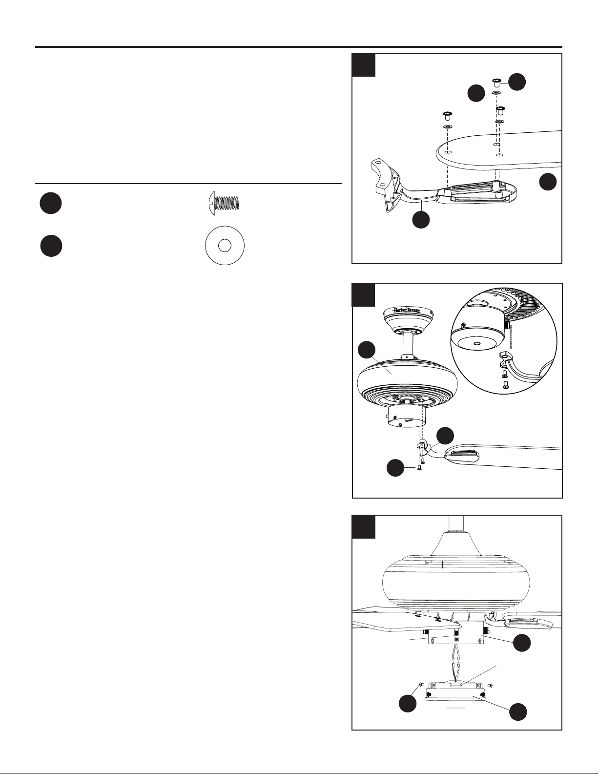
FINAL INSTALLATION
3. Partially insert the blade screws (BB) along with the
blade washers (CC) through the blade (M) and into the
blade arm (L). Tighten each blade screw (BB) with a
Phillips screwdriver (not included), starting with the one
in the middle.
Repeat this step for the remaining blades (M) and blade
arms (L).
Hardware Used
BB
Blade Screw x 15
Blade Washer x 15
4. Install the blade arm (L) to the underside of the motor
assembly (G) with motor screws (O) previously removed
(Step 6, page 8). Tighten with Phillips screwdriver.
Repeat for each blade arm (L).
5. Remove the three switch housing screws (T) from the
light kit (I). Then connect the single-pin connectors from
the switch housing (H) to the single-pin connectors from
the light kit (I) -- blue to black and white to white. Secure
the light kit (I) to the switch housing (H) using the three
switch housing screws (T).
Note: Align the notch in the light kit (I) with the reverse
switch on the switch housing (H).
CC
4
5
3
L
I
T
H
O
G
Reverse
Switch
Notch
BB
CC
M
L
I
T
H
Loading ...
Loading ...
Loading ...