Step 1: Verify that your home is equipped and up-to-date for proper operation
Installing a new water heater is the perfect time to examine your home’s plumbing system and make sure the system is up to current code standards. There have likely been plumbing code changes since the old water heater was installed. We recommend installing the following accessories and any other needed changes to bring your home up to the latest code requirements. UpdaƟ ng your plumbing system can help extend the life of your water heater, avoid damage to your home and property, and reduce the risk of serious injuries or death. Inspect your home and install any devices you need to comply with current codes and assure that your new water heater performs at its best. Check with your local plumbing official for more information.
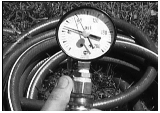
Water pressure
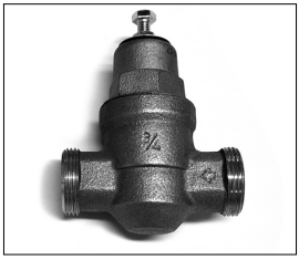
Most codes allow a maximum incoming water pressure of 80 psi (we recommend a working pressure no higher than 50-60 psi). Check your home’s water pressure with a pressure gauge and adjust if necessary. High water pressure can damage the water heater, piping, and other appliances.
HOW: Purchase an inexpensive water pressure gauge from Lowe’s®. Connect the water pressure gauge to an outside faucet and measure the maximum water pressure experienced throughout a 24-hour period ( highest water pressures often occur at night).
Figure 12 - Use a Water Pressure Gauge to make sure your home’s water pressure is not too high.
To adjust your home’s water pressure: Locate your home’s Pressure Reducing Valve (PRV) on the main incoming (cold) water supply line and adjust the water pressure control to between 50 and 60 psi. If your home does not have a Pressure Reducing Valve, install a PRV on the home’s main water supply line and set it to between 50 and 60 psi. Pressure Reducing Valves are available at Lowe’s®.
BACKGROUND: Over the years, many utilities have increased water supply pressures so they can serve more homes. In some homes today, pressures can exceed 100 psi. High water pressures can damage water heaters, causing premature leaks. If you have replaced toilet valves, had a water heater leak, or had to repair appliances connected to the plumbing system, pay particular attention to your home's water pressure. When purchasing a PRV, make sure the PRV has a built-in bypass.
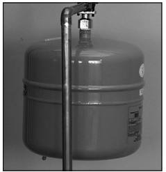
Water pressure increase caused by thermal expansion
Verify that you have a properly sized Thermal Expansion Tank. We recommend installing an expansion tank if your home does not have one. Plumbing codes require a properly pressurized, properly sized Thermal Expansion Tank in almost all homes.
Figure 13 - A Thermal Expansion Tank helps protect the home’s plumbing system from pressure spikes.
HOW: Connect the Thermal Expansion Tank (available from Lowe's® .) to the cold water supply line near the water heater. The expansion tank contains a bladder and an air charge. To work properly, the Thermal Expansion Tank must be sized according to the water heater's tank capacity and pressurized to match the home's incoming water pressure. Refer to the instructions provided with the Thermal Expansion Tank for installation details.
BACKGROUND: Water expands when heated, and the increased volume of water must have a place to go, or thermal expansion will cause large increases in water pressure (despite the use of a Pressure Reducing Valve in the home's main water supply line). The Safe Drinking Water Act of 1974 requires the use of backflow preventers and check valves to restrict water from your home reentering the public water system. Backflow preventers are often installed in water meters and may not be readily visible. As a result, most all plumbing systems today are now "closed," and almost all homes now need a Thermal Expansion Tank.
A Thermal Expansion Tank is a practical and inexpensive way to help avoid damage to the water heater, washing machine, dishwasher, ice maker, and even toilet valves. If your toilet occasionally runs for no apparent reason (usually briefly at night), that may be due to thermal expansion increasing the water pressure temporarily.
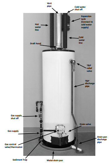
Water Pipe and Tank Leaks
Figure 14 - A metal drain pan piped to an adequate drain can help protect flooring from leaks and drips.
Leaks from plumbing pipes or from the water heater itself can damage property and could cause a fire risk.
• Install an automatic leak detection and shutoff device (available from Lowe's®). These devices can detect water leaks and can shut off the water heater's water supply if a leak occurs.
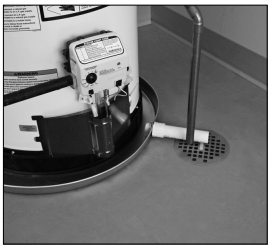
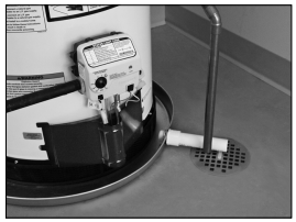
• Install a metal drain pan (available from Lowe's® ) under the water heater to catch condensation or leaks from the piping connections or tank. Most codes require, and we recommend, installing the water heater in a metal drain pan that is piped to an adequate drain. The drain pan must be at least two inches wider than the diameter of the water heater. Install the drain pan so the water level would be limited to a maximum depth of 1-3/4". The pan must not restrict air flow to the burner.
Water Temperature Regulation
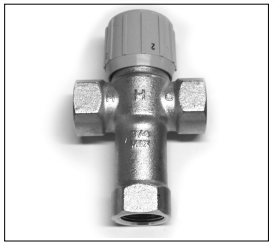
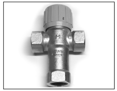
Install Thermostatic Mixing Valves to regulate the temperature of the water supplied to each point-of-use (for example, kitchen sink, bathroom sink, bath, shower). Install and adjust the mixing valve according to its manufacturer's instructions.
WARNING! Even if the water heater's thermostat is set to a relatively low temperature, hot water can scald. Install Thermostatic Mixing Valves at each point-of-use to reduce the risk of scalding.
Figure 15 - Thermostatic Mixing Valves installed at each point-of-use can help avoid scalding
BACKGROUND: A Thermostatic Mixing Valve, installed at each point-of-use, mixes hot water from the water heater with cold water to more precisely regulate the temperature of hot water supplied to fixtures. If you aren't sure if your plumbing system is equipped with properly installed and adjusted Thermostatic Mixing Valves at each point where hot water is used, contact a qualified person.
Step 2: Verify that the location is appropriate
WARNING! Do not store or use flammable materials, vapors, or liquids in the same location where this water heater is installed.
Before installing your water heater, ensure that it will be located:
• Indoors in an area with adequate air supply.
• In an area that will not freeze.
• As close as possible to a chimney or vent.
• In a metal drain pan piped to an adequate drain.
• In an area suitable for vertical installation.
• In an area with adequate space (clearances) for periodic servicing (there must be a minimum of 24 inches of front clearance).
• In an area that allows a minimum clearance from combustible surfaces as stated on the data plate.
• On a floor that can support the weight of a water heater full of water.
You will also want to follow these guidelines while considering an appropriate location:
• Do not install near air-moving devices such as exhaust fans, ventilation systems, or clothes dryers.
• Do not obtain ventilating air for the furnace/air handler from the same space as the water heater. Ensure that any return air ducts near the water heater are sealed.
• If the water heater is located in an area subject to lint, dust, or oily vapors, at least annually check and clean the air filter. See Maintenance section for steps on cleaning the air filter.
• Do not install in a bathroom, bedroom, or any occupied room normally kept closed.
• If the water heater is installed directly on carpeting, it shall be installed on a metal or wood panel extending beyond the full width and depth of the water heater by at least 3 in (76.2mm) in any direction. If the water heater is installed in an alcove or closet, the entire floor shall be covered by the aforestated panel.
• If your area is prone to earthquakes, use special straps as required by local building codes.
NOTICE: The state of California requires bracing, anchoring, or strapping the water heater to avoid its moving during an earthquake. Contact local utilities for code requirements in your area, visit website or call 1-916-445-8100 and request instructions. Other locations may have similar requirements. Check with your local and state authorities.
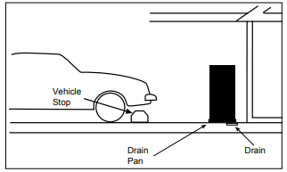
• Do not install in a location prone to physical damage by vehicles,
Figure 16 - In a garage, install a vehicle stop to avoid water heater damage.
• Avoid locations such as attcs, upper floors, or where a leak might damage the structure or furnishings. Due to the normal corrosive action of water, the tank will eventually leak. To minimize property damage from leaks, inspect and maintain your water heater in accordance with this manual's instructions. Install a metal drain pan under the water heater piped to an adequate drain. Inspect the drain pan, pipes, and surrounding area regularly and fix any leaks found.
Step 3: Removing the old water heater
1. Read each installation step and decide if you have the necessary skills to install the water heater. Only proceed if you are comfortable you can safely perform the work. If you are not sure, have a qualified person perform the installation.
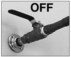
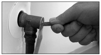
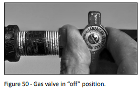
2. On the old water heater, turn the control knob on the gas control valve to the OFF position.
Figure 17 - Turn gas control/temperature knob OFF.
3. Turn the manual gas valve for the water heater's supply line OFF.
4. Open a hot water faucet and let the hot water run until it is cool (This may take 10 minutes or longer).
Figure 18 - Let the hot water run until it is cool.
WARNING! Be sure the water runs cool before draining the tank to reduce the risk of scalding.
5. Connect a garden hose to the drain valve and place the other end of the hose in a drain, outside, or in buckets. (Sediment in the bottom of the tank may clog the valve and prevent it from draining. If you can't get the tank to drain, contact a qualified person.)
6. Turn the cold water supply valve OFF.
Figure 19 - Cold water supply in off position.
7. Using a standard flat-blade screwdriver, open the drain valve. Sediment build up in the bottom of the water heater may hinder or prevent draining.
Figure 20 - Draining the old water heater.
8. Also open a hot water faucet to help the water in the tank drain faster.
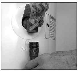
9. When the tank is empty, disconnect the Temperature & Pressure (T&P) Relief Valve discharge pipe. You may be able to reuse the discharge pipe, but do not reuse the old T&P Relief Valve. A new T&P Relief Valve comes with your new water heater.
Figure 21 - Removing the T&P Relief Valve discharge pipe.
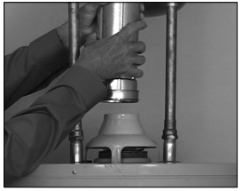
10. Allow the vent pipe and draft hood to cool. Once cooled, disconnect the vent pipe from the draft hood. You may need to support the vent pipe until the new water heater is in place.
Figure 22 - Disconnect the vent pipe from the draft hood.
11. Disconnect the water pipes. Many water pipes are connected by a threaded union which can be disconnected with wrenches. If you must cut the water pipes, cut the pipes close to the water heater's inlet and outlet connections, leaving the water pipes as long as possible. If necessary, you can make them shorter later when you install the new water heater.
12. Confirm the manual gas valve for the water heater's supply line is turned off. Disconnect the gas line from the water heater's gas control valve and cap it.
13. Remove the old water heater. Use an appliance dolly or hand truck to move the water heater.
WARNING! Use two or more people to remove or install a water heater. Failure to do so can result in back or other injury.
Step 4: Installing the New Water Heater
1. Completely read all instructions before beginning. If you are not sure you can safely complete the installation, seek assistance from any of the following sources:
• Lowe's® Professional Installation is available for this product and the work is guaranteed. Call your Lowe's® store to have this water heater installed.
• Schedule an appointment with a qualified person to install your water heater.
• Call our Technical Assistance Hotline at.
2. Install a metal drain pan that is piped to an adequate drain.
Figure 23 - Metal drain pan piped to drain.
3. Set the water heater in place taking care not to damage the drain pan. When installing directly on carpet, the water heater must be installed on a wood or metal base that extends beyond the dimensions of the water heater (width and depth) by at least 3 inches (76.2 mm) in any direction. If the water heater is installed on carpet in an alcove or closet, the entire floor must be covered by a wood or metal panel.
NOTICE: Most codes require setting the water heater in a metal drain pan piped to an adequate drain. The drain pan helps avoid property damage which may occur from condensation or leaks in the piping connections or tank. The drain pan must be at least two inches wider than the diameter of the water heater. Install the drain pan so the water level is limited to a maximum depth of 1-3/4".
4. Verify that the water heater is set in place properly. Check that:
• There is adequate space to install the T&P Relief Valve discharge pipe and that it can be piped to a separate drain (and not into the drain pan).
• There is adequate access and space around the water heater for future maintenance.
The water heater is installed vertically.
Step 5: Air Filter Installation
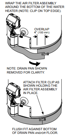
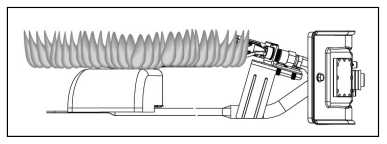
Once you've positioned the water heater in the installation area, install the wrap-around air filter (supplied with the water heater). The wrap-around air filter fits around the base of the unit. Do not operate the water heater without a clean air filter in place.
1. Before installing the Air Filter Assembly, remove any dust, lint or debris (including any packaging materials or tape) from under the water heater.
2. Installation: Wrap the filter around the base of the water heater. Cut to fit around a sensor if present. Trim excess filter material with scissors but allow filter material to overlap a few inches (see Figure 2).
3. The filter should fit snugly against base of the water heater with no gaps. The filter must fit flush against the bottom of the drain pan and/or floor. Hold the filter in place, then stretch the filter clip over the overlapped joint and hook in place (see Figure 24).
Figure 24 - Air Filter Installation
4. Check the filter at least every three months and clean as necessary. After installation, the filter may be cleaned by using a vacuum cleaner with a brush attachment to remove lint and dust.
NOTE: because the amount of dust and lint in the air can vary, your filter may need to be inspected/ cleaned more often. In some instances, the filter may need to be removed and washed using mild hand soap and water to remove any oily residue. After washing, allow to dry and properly reinstall.
Step 6: Connect the Temperature and Pressure (T&P) Relief Valve/Pipe
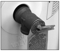
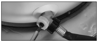
Connect the Temperature and Pressure (T&P) Relief Valve/Pipe Most T&P Relief Valves are preinstalled at the factory. In some cases, they are shipped in the carton and must be installed in the opening marked "T&P Relief Valve" and according to local codes.
Figure 25 - Temperature and Pressure Relief Valve
WARNING! To avoid serious injury or death from explosion, install a T&P Relief Valve according to the following instructions:
1. If the T&P Relief Valve was not factory installed, install the new T&P Relief Valve that came with your water heater. Do not reuse an old T&P Relief Valve.
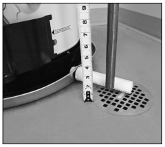
• The discharge pipe should be at least 3/4" inside diameter and sloped for proper drainage. Install it to allow complete drainage of both the T&P Relief Valve and the discharge pipe.
Figure 26 - Temperature and Pressure Relief Valve Pipe
The the pipe size of the T&P Relief discharge pipe must not be smaller than Valve. The pipe must also be able to withstand 250°F (121°C) without distortion. Use only copper or CPVC pipe. Do not use any other type of pipe, such as PVC, iron, flexible plastic pipe, or any type of hose.
Terminate the discharge pipe a maximum of six inches above a floor drain or outside the building. Do not drain the discharge pipe into the drain pan; instead pipe it separately to an adequate drain. In cold climates, terminate the discharge pipe inside the building to an adequate drain. Outside drains could freeze and obstruct the drain line—protect the discharge pipe from freezing.
Do not place any valve or other restriction between the tank and T&P Relief Valve. Do not cap, block, plug, or insert any valve between the T&P Relief Valve and the end of the discharge pipe. Do not insert or install any reducer in the discharge pipe.
Step 7: Install Shutoff and Thermostatic Mixing Valves
1. If one is not already installed, install a manual shutoff valve in the cold water line that supplies the water heater. Install the shutoff valve near the water heater so that it is readily accessible. Only use a full-flow ball or gate valve compatible with potable water.
2. Install a Thermostatic Mixing Valve at each point-of-use (for example, kitchen sink, bathroom sink, bath, shower) per the valve manufacturer's instructions.
Figure 27 - Install Thermostatic Mixing Valves at each point where hot water will be used.
WARNING! Even if the water heater's thermostat is set to a relatively low temperature, hot water can scald. Install Thermostatic Mixing Valves at each point-of-use to reduce the risk of scalding.
3. For water heaters that are fed by a solar water heating system (or any other preheating system), always install a Thermostatic Mixing Valve or other temperature limiting device in the inlet water supply line to limit water supply inlet temperature to 120°F. Solar water heating systems can supply water with temperatures exceeding 180°F and may result in water heater malfunction.
WARNING! Hot water provided by solar heating systems can cause severe burns instantly, resulting in severe injury or death.
Step 8: Connect the Water Supply
Note that all piping and components connected to the water heater must be suitable for use with potable water.
1. Determine the type of water pipes in your home. Most homes use copper water pipes, but some use CPVC or cross-linked polyethylene (PEX). Use fittings appropriate for the type of pipe in your home. Do not use iron or PVC pipe.
2. Connect the cold water supply using 3/4 inch National Pipe Thread "NPT" to the fitting marked "C" (COLD).
For ease of removing the water heater for service or replacement, connect the water pipes with a coupling called a union. We recommend using a dielectric-type union (available from Lowe's). Dielectric unions can help prevent corrosion caused by tiny electric currents common in copper water pipes and can help extend the life of the water heater
NOTICE: Most water heater models contain energy saving heat traps in the inlet and outlet connections. Do not remove the heat traps.
3. Connect the hot water supply using 3/4 inch NPT to the tiffing marked "H" (HOT).
4. Install insulation (or heat tape) on the water pipes especially if the indoor installation area is subject to freezing temperatures. Insulating the hot water pipes can increase energy efficiency.
5. Adjust (or install) the home's Pressure Reducing Valve to 50-60 psi and install a Thermal Expansion Tank.
Figure 28 - A Pressure Reducing Valve is required if your home’s water pressure is above 80 psi.
Figure 29 - The Thermal Expansion Tank should be pressurized with air, using a hand pump, to match the home’s incoming water pressure.
Step 9: Verify Connections and Completely Fill Tank
To remove air from the tank and allow the tank to fill completely with water, follow these steps:
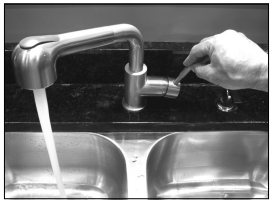
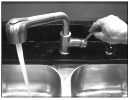
Remove the aerator at the nearest hot water faucet. This allows debris in plumbing system to be washed out of the pipes.
Turn the cold water supply back on and till the tank.
Open a hot water faucet and allow the water to run until it flows with a full stream.
Let the water run full stream for three minutes.
Close the hot water faucet and replace the aerator.
Check inlet and outlet connections and water pipes for leaks. Dry pipes connections so that any drips or leaks will be apparent. Repair any leaks. Almost all leaks occur at connections and are not a tank leak.
Step 10: Install Draft Hood
1. Install the new draft hood by aligning the legs and inserting them into the slots provided on top of the water heater. Do not reuse the draft hood from the old water heater, but rather use the new one that came with your new water heater.
2. Secure the draft hood using the four screws provided. Attach the home's existing vent pipe to the draft hood outlet using an approved vent adapter (not supplied).
Figure 30 - Install the new draft hood and secure with screws.
3. Secure the vent adapter to the draft hood with sheet metal screws. Read the Venting section on page 11. Make sure your home's venting system complies with the instructions in this manual and is in good condition.
Step 11: Make Gas Connections
The Gas Water Heater Hook-Up Kit (available at Lowe's®) includes a flexible gas connector with compression fiffings to connect the home's gas line to the water heater's gas control valve. Follow the kit's installation instructions to attach the flexible gas connector.
Figure 31 - Flexible gas line connector.
Once you've made the gas connections, use a small, soft-bristled brush to apply a hand dishwashing soap and water mixture or children's soap bubbles (1 part soap to 15 parts water) to all connection points of the gas line and flexible gas connector (if used). Make sure to generously coat all the connections and check for gas leaks (which will appear as small bubbles). If any leaks are detected, turn the gas supply off, tighten the leaking connection and re-check.
BEFORE LIGHTING THE WATER HEATER...
Make sure all checklist items have been completed.
Water Heater Location
✓ Installation area free of corrosive or flammable materials, liquids or vapors.
✓ Proper clearances from combustible surfaces maintained and sufficient room to service the water heater.
✓ Not installed directly on a carpeted floor.
✓ Metal drain pan installed and piped to an adequate drain.
✓ Water heater not located near an air moving device (fan, clothes dryer).
✓ Not in a location with large amounts of lint, dust, etc. (If so, the air filter or flame arrestor located on the bottom of the water heater will need to be cleaned more often.)
Combustion Air Supply and Ventilation
✓ Adequate air supply for water heater and any other nearby gas appliances.
If the water heater is installed in a closet or other small, enclosed space or within the living space of the house, air supply openings needed.
✓ Are the openings of sufficient size?
✓ Ductwork is the same cross-sectional area as the openings?
✓ Outside air openings are preferred and may be required in tightly built homes.
Vent Pipe System
✓ New draft hood, properly installed.
✓ Vent pipe securely fastened to draft hood with screws and supported properly.
✓ Vent pipe made of approved material and either 2" or 3" in diameter.
✓ Vent system installed according to local and state codes or, in the absence of local and state codes, the "National Fuel Gas Code", ANSI Z223.1(NFPA 54)-current edition.
✓ Check existing vent system for rust, restrictions/obstructions.
Water System Piping
✓ Temperature and pressure relief valve properly installed with a discharge line run to an adequate drain and protected from freezing.
✓ Water pipes free of leaks.
✓ Water heater completely filled with water.
✓ Thermal Expansion Tank installed
✓ Water Pressure Reducing Valve installed and adjusted to 50-60 psi.
✓ Thermostatic Mixing Valves installed at each point-of-use.
Gas Supply and Piping
✓ Gas type is the same as that listed on the water heater's data plate.
✓ Gas line equipped with shut-off valve.
✓ Adequate gas pipe size and approved gas pipe material.
✓ All gas connections and fiffings leak checked and any leaks corrected.
OPERATION
Lighting Instructions
WARNING! Explosion Hazard -Replace viewport if glass is missing or damaged. Failure to do so can result in death, explosion or fire.
Read and understand these directions thoroughly before attempting to light or re-light the pilot. Make sure the viewport is not missing or damaged. Make sure the tank is completely filled with water before lighting the pilot. Check the data plate near the gas control valve to ensure the correct gas type. Do not use this water heater with any gas other than the one listed on the data plate. If you have any questions or doubts, consult your gas supplier or gas utility company.
NOTICE! A newly installed water heater will have air in the gas line. It may take several lighting attempts to clear all the air from the gas line and light the pilot. Follow these steps to light the pilot:
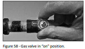
1. Make sure the manual gas valve for the water heater's supply line is ON.
Figure 32 - Gas valve in “on” position
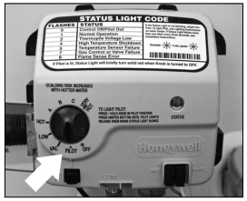
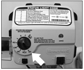
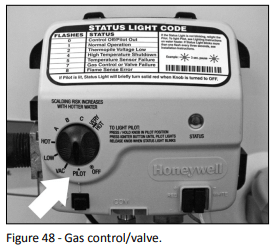
2. Turn the gas control knob to the PILOT position.
Figure 33 - Gas control/valve.
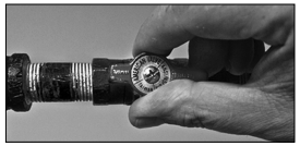
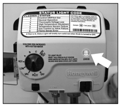
3. Press the gas control knob in fully and hold it in. While holding in the gas control knob, repeatedly click the igniter button (approximately once per second) for up to 90 seconds or until the Status Light starts to flash. You can tell the pilot is lit when the Status Light flashes once every three seconds.
Figure 34 - Status light.
4. Once the Status Light starts flashing, release the gas control knob. Adjust the gas control knob to the desired temperature setting.
5. If the Status Light doesn't start flashing after 90 seconds, release the gas control knob and wait 10 minutes.
6. Repeat lighting steps 2 through 5 at least two additional times or until the Status Light starts flashing once every three seconds. Wait 10 minutes between lighting attempts.
7. A solid Status Light means the pilot was lit but is now off. Release the gas control knob and wait 10 minutes. Once the Status Light goes out, repeat lighting steps 2 through 5.
8. If the Status Light doesn’t start flashing after three lighting attempts, turn the gas control knob to the OFF position and refer to the “Troubleshooting-No Hot Water” section (see page 25).
9. When a gas water heater is first lit and the tank is cold, condensation often forms inside the water heater. You may hear drips or a sizzling sound when the water heater is first lit or, you may see a small puddle on the floor. Condensation is not a leak and will go away once the tank reaches normal operating temperature.
10. The air filter at the bottom of the water heater must be cleaned from time to time. See the Maintenance section for steps on cleaning the air filter. If the air filter is not cleaned as needed, the water heater's pilot may go out.
Shut down Instructions
Turn the gas control/temperature knob counterclockwise to the "OFF" seffing. The status light will stop blinking and stay on for a short time after the water heater is turned off.
Emergency Shut down
Should overheating occur or the gas supply fail to shut off, turn off the water heater's manual gas control valve and call a qualified person.
Checking the Vent System and Air Supply
Once the water heater is lit and the gas control knob is set to the desired temperature, the burner will light (if the tank is cold). Perform an air supply and vent test to make sure the unit is venting properly and the air supply is adequate:
1. The main burner must be on for this test. With a newly installed water heater full of cold water, turning the temperature control knob to HOT should cause the main burner to come on. You can view the burner through the sight glass at the base of the water heater.
2. Close all windows and doors and turn on all gas appliances and air-moving devices ( range hoods, bathroom exhaust fans, ceiling fans, etc.) in your home. Also, close any fireplace dampers.
3. Allow the water heater's main 3 burner to operate for five minutes. Pass a newly extinguished match approximately one inch from the draft hood's relief opening. Smoke from the match should be steadily drawn into the opening indicating the water heater is getting adequate air and the vent system is working.
Figure 35 - Test the air supply and vent to make sure the water heater has adequate air and is venting properly.
4. If the main burner has been operating for five minutes but the match smoke driffs around or is blown away from the opening, turn the gas control knob OFF. Inspect the vent system and repair if necessary. In many cases, failure to pass the air supply and vent test indicates the water heater is not getting enough air or there is a problem with the vent system. It may be necessary to increase the air supply by getting air from outside (see page 7).
WARNING! Burn Hazard. Do not touch the vent, doing so can cause burns. If the draft hood does not draw in smoke from a match after five minutes of main burner operation, shut the gas supply off, and do not operate the water heater until the vent system and air supply have been checked by a qualified person and repaired if necessary. Continuing to operate the water heater in this condition could lead to serious injury or death from carbon monoxide poisoning.
Temperature Control System
Adjusting the Temperature
With the installation steps completed, you may adjust the water heater's temperature setting if desired.
1. Set the gas valve to the desired temperature. The “HOT" setting sets the water temperature to approximately 120°F, reducing the risk of scald injury. You may wish to set a higher temperature to provide hot water for automatic dishwashers or laundry machines, to provide more hot water capacity, and to reduce bacterial growth. Higher tank temperatures (140° F) kill bacteria that cause a condition known as “smelly water" and can reduce the levels of bacteria that cause water-borne diseases.
Water usage patterns, as well as heat from sources such as solar collectors, ambient air, and the pilot light can result in temperatures higher than the thermostat set-point.
WARNING! Higher temperatures increase the risk of scalding, but even at 120°F, hot water can scald (see Table 1). Install Thermostatic Mixing Valve(s) at each point-of-use to reduce the risk of scalding.
2. To adjust the water heater's thermostat:
Figure 36 - Adjust the gas control knob to “HOT”.
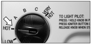
Turn the gas control knob on the gas control valve to the right to the following settings.
• “A" 128°F
• “B" 138°F
• “C" 147°F
• “VERY HOT" 160°F
NOTICE: The temperatures above are approximates. The actual temperature of the heated water may vary.
NOTICE: If the tank is full of cold water, condensation may form inside the water heater. This condensation may drop on the burner causing a sizzling sound. In some cases, you may see a small puddle on the floor. Condensation is normal and should go away once the tank reaches its normal operating procedure.
WARNING! If you have increased the temperature setf ng and the Thermostatic Mixing Valves are not set properly (or not installed) you could scald yourself while checking the temperature.
Check water temperature at several points of use in your home (for example, bathtub faucet, shower, or lavatory sink) and adjust the Thermostatic Mixing Valves as needed. If you aren't sure how to adjust the Thermostatic Mixing Valve settings, or aren't sure if you have Thermostatic Mixing Valves, contact a qualified person.
Operating Modes
The gas control valve has two different operating modes: Standard and Vacation. The Standard mode allows you to adjust the water temperature to your desired setting. The Vacation (VAC) mode sets the thermostat at approximately 55°F and is recommended when not using hot water for an extended period of time. The VAC setting also reduces energy losses and keeps the tank from freezing during cold weather but can cause a Hydrogen gas build up. See caution on page 6.
TROUBLESHOOTING
No Hot Water
Use the following step-by-step plan as a guide to help determine why you have no hot water:
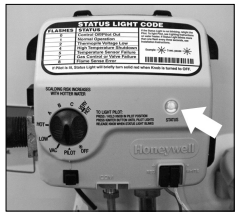
1. Check the Status Light
The Status Light on the gas control valve flashes once every three seconds if the pilot is lit and the gas control valve has not detected any problems.
Figure 37 - Status light.
If the Status Light is flashing once every three seconds and you have no hot water, make sure the gas control knob is set to HOT.
If the Status Light flashes more than once every three seconds, refer to the Status Light Code Troubleshooting Chart on page 27.
If the Status Light is not flashing, go to step 2.
2. Status Light is Not Flashing
If the Status Light isn't flashing, try lighting the pilot using the lighting instructions on page 23.
If you have tried lighting the pilot and the Status Light does not flash, go to step 3.
If the Status Light flashes, go to Step 1.
3. Checking the Pilot Light
Check the spark igniter. Dim the room lights and look through the viewport while clicking the igniter button.
If you don't see a spark through the viewport, check to make sure the igniter wire is firmly inserted into the white connector.
If you see a spark, make sure the gas supply valve is turned on, and try lighting the pilot using the lighting instructions on page 23.
If the pilot still does not light, call a qualified person.
Insufficient Hot Water or Slow Hot Water Recovery
WARNING! Because of the increased risk from scalding, if you set the water heater's gas control knob higher than 120°F, install Thermostatic Mixing Valves at each point-of-use. Due to the increased risk of scalding, do not set the temperature of the Thermostatic Mixing Valves above 120°F.
If the hot water is simply not warm enough, there are several possible causes:
• Faulty Thermostatic Mixing Valve in a faucet or shower control (check other faucets in the house for hot water).
• Water heater's capacity too small (or usage too high).
• Reversed plumbing connections or melted dip tube (usually found soon after new installation).
• Plumbing leak.
• Sediment or lime build up in the bottom of the tank.
Thermostatic Mixing Valves. If the hot water is simply not warm enough, make sure the faucet you are checking doesn't have a defective Thermostatic Mixing Valve. Many shower controls now have built-in mixing valves. If these devices fail, they can reduce the amount of hot water the shower or faucet delivers even though there is plenty of hot water in the tank. Always check the water temperature at several faucets to make sure the problem is not in a faucet or shower control.
Undersized Water Heater. If your water heater runs out of hot water quickly, it may be too small for your needs. If the water heater is old, consider replacing it with a larger model. If the water heater is in good condition, you may be able to meet your family's hot water needs with the existing water heater by installing Thermostatic Mixing Valves at each point-of-use and then turning the gas control knob to a higher setting.
You can also reduce your home's hot water needs by washing clothes in cold water, installing flow restrictors on shower heads, repairing leaky faucets, and taking other conservation steps.
Reversed Connections or Melted Dip Tube. Check the hot and cold water connections and make sure your home's hot water pipe is connected to the hot water outlet on the water heater. Usually, reversed connections are found soon after the installation of a new unit. If copper pipes were soldered while they were attached to the water heater, the dip tube may have melted. The dip tube is a long, plastic tube inside the tank attached to the cold water inlet. If the dip tube has melted, it can be replaced by removing the cold water inlet connection, removing the old dip tube and installing a new one.
Plumbing Leak. Even a small leak in the hot water side of the home's plumbing system can make it appear that the water heater is producing little to no hot water. In this case, the burner will be on all or almost all the time, yet you will have very little hot water. Locate and repair the leak.
Sediment or Lime in Tank. With an existing water heater, if you have some hot water but not as much as you're used to, there may be a build up of sediment or lime on the bottom of the tank. Sediment or lime build up can reduce the efficiency of your water heater. Heavy deposits can damage the water heater. See the Maintenance section for steps on draining and flushing the water heater.
Temperature Too High
Adjust the thermostat on the water heater to a lower setting. Install or adjust Thermostatic Mixing Valves for each point-of-use (see the valve manufacturer's instructions).
Low Water Pressure
Check both the cold and hot water at a sink to determine if the lower pressure is only on the hot water side. If both hot and cold faucets have low pressure, call your local water utility.
If the low pressure is only on the hot water side, the primary causes are:
• Melted heat traps or dip tube. Soldering copper pipes while they are connected to the water heater can melt the heat traps inside the hot and cold water connections or the dip tube (cold water side). Melted heat traps or a melted dip tube can restrict the flow of hot water. If that's the case, replace the heat traps or dip tube.
• Partially closed supply valve. Open the water heater's supply valve fully.
Drips from T&P Relief Valve Discharge Pipe
A small amount of water dripping from the Temperature and Pressure (T&P) Relief Valve usually means the home's water pressure is too high and/or you need a Thermal Expansion Tank. See Step 1 in the Installation section of this manual for more information.
A large amount of hot water coming from the T&P discharge pipe may be due to the tank overheating. If the T&P relief valve is discharging large amounts of very hot water, turn the gas supply valve off and call a qualified person.
WARNING! Do not cap or plug the T&P Relief Valve or discharge pipe, and do not operate the water heater without a functioning T&P Relief Valve—this could cause an explosion.
Water Pressure too High. High water pressure can cause the T&P Relief Valve to drip. Install a Pressure Reducing Valve (PRV) on the main cold water supply line. Adjust the PRV to between 50 and 60 psi.
Thermal Expansion Tank. Install a Thermal Expansion Tank. If a Thermal Expansion Tank is already installed and the T&P Relief Valve discharge pipe drips, the home's water pressure may be too high or the Thermal Expansion Tank may be defective. Refer to the instructions that came with the Thermal Expansion Tank for more information.
Debris. In rare cases, debris can stick inside the T&P Relief Valve preventing the valve from sealing fully. In that case, the T&P Relief Valve discharge pipe will drip. You may be able to clear debris from the T&P Relief Valve by manually operating the valve, allowing small quantities of water to flush out the debris. See the label on the T&P Relief Valve for instructions.
WARNING! When manually operating the temperature-pressure relief valve, make sure that no one is in front of or around the discharge outlet. The water may be extremely hot and could cause severe burns. Also ensure that the water discharge will not cause property damage.
If the water pressure is between 50 and 60 psi, a Thermal Expansion Tank is installed and properly pressurized, and the valve has been cleared of any debris, and it still drips, the valve may be broken—have a qualified person replace the T&P Relief Valve.
Water Odor
Harmless bacteria normally present in tap water can multiply in water heaters and give off a "rotten egg" smell. Although eliminating the bacteria that causes "smelly water" is the only sure treatment, in some cases, the standard anode rod that came with your water heater can be replaced with a special zinc anode rod which may help reduce or eliminate the odor. Contact a qualified person.
NOTICE: To protect the tank, an anode rod must be installed in the water heater at all times or the warranty is void.
In cases where the "rotten egg" smell is very strong, you could increase the tank temperature to 140°F in order to reduce bacterial growth in the tank.
WARNING! Because higher temperatures increase the risk of scalding, if you set the thermostat(s) higher than 120°F, Thermostatic Mixing Valves at each point-of-use are particularly important.
STATUS LIGHT CODE TROUBLESHOOTING CHART
LED STATUS
PROBLEM
CORRECTIVE ACTION
0. FLASHES (LED NOT LIT)
Pilot light is not lit. Not enough power (millivolts) to keep it lit.
Follow the lighting instructions on the front of the water heater and record any diagnostic codes.
1. FLASH (EVERY 3 SECONDS)
Normal operation.
No corrective action necessary.
2. FLASHES
Insufficient power (millivolts) to the gas control valve/thermostat.
1. Check all wiring connections. If problem persists proceed to step 2.
2. Replace the thermopile.
4. FLASHES
High water temperature has activated the over heat sensor.
Replace the gas control valve/thermostat.
5. FLASHES
Sensor failure
Replace the gas control valve/thermostat.
7. FLASHES
Gas Control Valve/Thermostat failure.
Replace the gas control valve/thermostat.
8. FLASHES
This condition only appears if the gas control/temperature knob has been turned off and the thermopile continued to produce electric power. This condition can occur if the thermopile does not cool down as quickly as expected when the unit is shut off. This condition can also occur if the gas control/ temperature knob has been turned off and the pilot continues to operate because the pilot valve is stuck in the open position.
Make sure that the gas control valve/thermostat knob is set to OFF. Wait one minute. Remove the outer door. Look through the sight glass for a pilot flame. If a pilot flame is observed with the gas control valve/thermostat knob set to the OFF position, the pilot valve is stuck open. Turn the main gas supply OFF. Replace the gas control valve/ thermostat.
If the pilot flame is not observed when the gas control valve/thermostat knob is set to the OFF position, wait 10 minutes for the thermopile to cool, then attempt to relight the pilot by following the lighting instructions on the water heater’s label. If this condition returns, replace the gas control valve/ thermostat.
MAINTENANCE
Routine Maintenance
Routine maintenance will help your water heater last longer and work better. If you can't perform these routine maintenance tasks yourself, contact a qualified person.
Draining and Flushing the Water Heater
Tap water contains minerals that can form sediment in the bottom of the tank. The amount of sediment formed depends on the hardness of your tap water, the temperature settings, and other variables. We recommend draining and flushing the water heater after the first six months of operation to determine the amount of sediment build up. If there is little sediment, drain and flush the tank annually. If there is a lot of sediment, drain and flush the tank more often. Draining sediment extends the life of the water heater.
To Drain and Flush the Tank:
1. Turn the gas control knob on the gas control valve to the OFF position.
Figure 40 - Turn gas control/temperature knob OFF.
2. Turn the manual gas valve for the water heater's supply line OFF.
3. Open a hot water faucet and let the hot water run until it is cool (This may take 10 minutes or longer).
Figure 41 - Let the hot water run until it is cool.
WARNING! Be sure the water runs cool before draining the tank to reduce the risk of scalding.
4. Connect a garden hose to the drain valve and place the other end of the hose in a drain, outside, or in buckets. Note that sediment in the bottom of the tank may clog the valve and prevent it from draining. If you can't get the tank to drain, contact a qualified person.
5. Turn the cold water supply valve OFF.
6. Open the drain valve on the water heater.
Figure 42 - Draining the water heater.
7. Also open a hot water faucet to help the water in the tank drain faster.
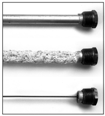
8. Remove and inspect the anode rod and replace if depleted. The anode rod requires a 1-1/16" socket.
Figure 43 - Anode rods from new (top) to partially depleted (middle) to fully depleted stage (bottom).
Anode Rod. The anode rod is a sacrificial metal rod that helps avoid corrosion and premature failure (leaks) in the tank. The anode rod is a consumable item. Inspect the anode rod after the first six months of operation when you drain and flush the tank. Replace the anode rod if it is substantially worn out or depleted. Thereafter, inspect the anode rod annually or more frequently if needed. If you use a water softener, your anode rod will deplete faster than normal. Inspect the anode rod more frequently, replacing the anode rod if it is depleted. Obtain a new anode rod from Lowe's® or have a qualified person replace it. (Anode rods are a consumable item and are not covered under warranty).
9. If a large amount of sediment was present when the tank was drained, flush the tank by opening the cold water supply valve and letting the water run until no more sediment drains from the tank. Close the drain valve when you are done.
10. Refill the tank by opening the cold water supply valve. Make sure a hot water faucet is open and the drain valve is closed. Allow a hot water faucet to run full for at least three minutes to make sure the tank has all the air removed and is completely full of water. Once you are certain the tank is completely full of water, close the hot water faucet.
11. Relight the pilot using the instructions on page 23 and adjust the gas control knob to the desired temperature. It may take an hour or more for the tank of cold water to heat up.
Visual Inspection
On an annual basis, visually inspect the venting and air supply system, piping systems, main burner, pilot burner, and the air filter.
Check the water heater for the following:
• Obstructions, damage, or deterioration in the venting system. Make sure the ventilation and combustion air supplies are not obstructed. Check the air filter for dust or other debris and clean if needed.
• Build up of soot and carbon on the main burner and pilot burner. The burner may be cleaned with soap and hot water.
• Inspect the burner flames through the viewport and compare them to the drawing below. A properly operating burner should produce a soft blue flame. Blue tips with yellow inner cones are satisfactory. The tips of the flame may have a slight yellow tint. The flame should not be all yellow or have a sharp blue-orange color. Contaminated air may cause an orange colored flame. Contact a qualified technician if the flame is not satisfactory.
Figure 44 - Burner Flames
• Leaking or damaged water and gas piping.
• Remove any flammable, corrosive or combustible materials near the water heater.
If you lack the necessary skills required to properly perform this visual inspection or if the burner needs to be cleaned, get help from a qualified person.
T&P Relief Valve Maintenance
Figure 45 - T&P Relief Valve.
Read and follow the operating and annual maintenance instructions provided by the manufacturer of the T&P Relief Valve (yellow label attached to T&P Relief Valve). Minerals in the water can form deposits that cause the valve to stick or create blocked passages, making the T&P Relief Valve inoperative. Follow these guidelines:
• At least annually, operate the T&P Relief Valve manually to ensure the waterways are clear and the valve mechanism moves freely (above). Before operating the valve manually, check that it will discharge in a place for secure disposal.
WARNING! Hot water will be released. Before operating the T&P relief valve manually, check that it will discharge in a safe place. If water does not flow freely from the end of the discharge pipe, turn the gas control knob to the OFF position and call a qualified person to determine the cause.
• At least every five years, have a qualified person inspect the T&P Relief Valve and discharge pipe. Damage caused by corrosive water conditions, mineral deposits, or other problems can only be determined when a qualified person removes and inspects the valve and its components.
A dripping T&P Relief Valve is usually caused by the home's water pressure being too high or the lack of a Thermal Expansion Tank. If your T&P Relief Valve drips, see page 26.
A T&P relief valve that has been allowed to drip for an appreciable period of time should be inspected for mineral buildup. See T&P relief valve tag for more information.
Inspect and Clean the Air Filter
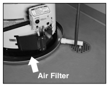
Figure 46 - Clean air filter periodically.
An air filter should be installed around the base of the water heater. At least annually inspect the air filter and check for a build-up of dust or debris.
Vacuum the filter to remove any dust or debris. If an oily residue is present on the filter, wash it in soap and water, then dry the filter.
Removing and Replacing the Gas Control Valve/Thermostat
IMPORTANT: The gas control valve/ thermostat is a standard valve with wire leads that connect to a thermal switch.
Removing the Gas Control Valve/ Thermostat:
1. Turn the gas control/temperature knob to the “OFF” position.
2. Turn off the gas at the manual shut-off valve on the gas supply pipe.
3. Drain the water heater. Refer to the "Draining and Flushing the Water Heater" section (see page 28) and follow the procedure.
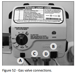
4. Disconnect the A igniter wire from the igniter lead wire. Use needle nose pliers to disconnect the B red (+) and white (-) thermopile wires. Disconnect C pilot tube (7/16" wrench) and D manifold tube (3/4" wrench) at the gas control valve/thermostat. NOTE: L.P. Gas systems use reverse (left-hand) threads on the manifold tube.
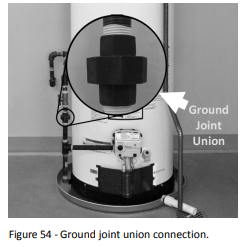
5. Disconnect the ground joint union in the gas piping. Disconnect the remaining pipe from the gas control valve/ thermostat.6.
6. To remove the gas control valve/thermostat, thread a 4" section of gas pipe into the inlet and use it to turn theFlame Lock® Safety System Operational Checklist TROUBLESHOOTING CHART gas control valve/thermostat (counterclockwise.) Do not use pipe wrench or equivalent to grip body. Damage may result, causing leaks. Do not insert any sharp objects into the inlet or outlet connections. Damage to the gas control valve/ thermostat may result.
Replacing Gas Control Valve/Thermostat:
To replace the gas control valve/thermostat, reassemble in reverse order. When replacing the gas control valve/ thermostat, thread a 4" section of gas pipe into the inlet and use it to turn the gas control valve/thermostat (clockwise.) DO NOT OVER TIGHTEN, damage may result.
• Be sure to use approved Teflon® tape or pipe joint compound on the gas piping connections and tiffing on the back of the gas control valve that screws into tank.
• Be sure to remove the pilot ferrule nut from the new gas control valve/thermo-stat.
• Turn the gas supply on and check for leaks. Test the water heater by brushing on an approved noncorrosive leak detection solution. Bubbles forming indicate a leak. Correct any leak found.
• Be sure tank is completely tilled with water before lighting and activating the water heater. Follow the "Lighting Instructions" on page 23.
• If additional information is required, contact the Service Department at: 1-877-817-6750.