Loading ...
Loading ...
Loading ...
Installation en
15
Preparing the ceiling
■ The ceiling must be flat, horizontal and have
adequate load-bearing capacity.
■ The depth of the bore holes must be the same
length as the screws. The wall plugs must have a
secure grip.
■ The enclosed screws and wall plugs are suitable for
solid brickwork. Suitable fasteners must be used for
other structures (e.g. plasterboard, porous concrete,
poroton bricks).
■ The max. weight of the extractor hood is 50 kg.
Electrical connection
:Warning – Risk of electric shock!
Components inside the appliance may have sharp
edges. These may damage the connecting cable. Do
not kink or pinch the connecting cable during
installation.
The required connection data can be found on the
rating plate inside the appliance; to do this, remove the
metal mesh grease filter.
Length of the cable: approx. 1.30 m
This appliance complies with the EC interference
suppression regulations.
:Warning – Risk of electric shock!
It must always be possible to disconnect the appliance
from the electricity supply. The appliance must only be
connected to a protective contact socket that has been
correctly installed.
The mains plug of the mains power cable must be
easily accessible after installation of the appliance. If
this is not possible, an all-pole isolating switch must be
integrated into the permanent electrical installation
according to the conditions of overvoltage category III
and according to the installation regulations.
The permanent electrical installation must only be wired
by a professional electrician. We recommend installing
a residual-current circuit breaker (RCCB) in the
appliance's power supply circuit.
5Installation
Installation
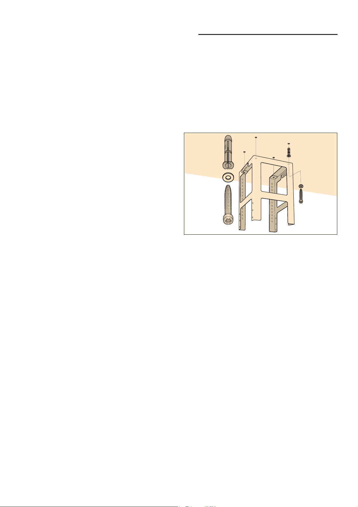
Fitting the upper support frame
1. Before fitting, determine the total height of the
support frame and mark the screw holes.
Note: The height of the support frame can be
adjusted in 20 mm intervals.
2. On the ceiling, mark the centre point of the
appliance.
3. Using the enclosed template, mark the positions for
the screws on the ceiling.
4. Drill four 8 mm diameter holes to a depth of 80 mm
for the fasteners and press in the wall plugs flush
with the ceiling.
5. Fasten the upper part of the support frame to the
ceiling with 4 screws.
Note: Ensure that the support frame is in the correct
position. The middle bracket defines the preferred
side and must be facing the hob control elements.
[
[
[
Loading ...
Loading ...
Loading ...