1
WELCOME
Thank you for purchasing a P olaris vehicle, and welcome to our
world-wide family of Polaris owners. We proudly produce an exciting
line of utility and recreational products:
S Snowmobiles
S All-terrain vehicles (ATVs) and Quadricycles
S RANGER utility vehicles
S Victory motorcycles
Always follow the instructions and recommendations in this manual.
The manual contains instructions for minor maintenance, but
information about major repairs is outlined in the Polaris Service
Manual and should be performed only by a Factory Certified Master
Service Dealer (MSD) Technician. P lease see your dealer for all of
your service needs during (and after) the warranty period.
For more information about Polaris, visit us online at
www.polarisindustries.com.

2
Copyright 2005 Polaris Sales Inc. All information contained with in this publication is
based on the latest product information at the time of publication. Due to constant
improvements in the design and quality of production components, some minor
discrepancies may result between the actual vehicle and the information presented in this
publication. Depictions and/or procedures in this publication are intended for reference
use only. Manufacturer accepts no liability for omissions or inaccuracies. Any reprinting
or reuse of the depictions and/or procedures contained within, whether whole or in part,
is expressly prohibited.
Printed in U.S.A.
2006 Sportsman 500/500 EFI International Owner’s Manual P/N 9920545

3
TABLE OF CONTENTS
VEHICLE IDENTIFICATION NUMBERS 5...............
SAFETY 6..........................................
FEATURES AND CONTROLS 38......................
OPERATION 55.....................................
EMISSION CONTROL SYSTEMS 62...................
MAINTENANCE AND LUBRICATION 63................
POLARIS PRODUCTS 111............................
SPECIFICATIONS 112................................
TROUBLESHOOTING 115............................
WARRANTY 119.....................................
MAINTENANCE LOG 121.............................
INDEX 124..........................................

4
1
31XX
3
2
5
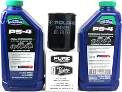
VEHICLE IDENTIFICATION NUMBERS
Record your vehicle’s identification numbers and key number.
Remove the spare key and store it in a safe place. Your key can be
duplicated only by mating a Polaris key blank with one of your
existing keys, so if both keys are lost, the ignition switch must be
replaced.
Vehicle Model Number:
Frame VIN (1)(right front):
Engine Serial Number (2):
(right front of engine)
Key Number (3):

6
SAFETY
Operator Safety
The following signal words and symbols appear throughout this
manual and on your vehicle. Become familiar with their meanings
before reading the manual.
The safety alert symbol, on your vehicle or in this manual, alerts
you to the potential for personal injury.
WARNING
The safety alert warning indicates a potential hazard that may
result in serious injury or death.
CAUTION
The safety alert caution indicates a potential hazard that may
result in minor personal injury or damage to the vehicle.
CAUTION
A caution indicates a situation that may result in damage to the
vehicle.
NOTE:
A note will alert you to important information or instructions.

7
SAFETY
Operator Safety
WARNING
Failure to follow the warnings in this manual can result in serious
injury or death.
A Polaris Quadricycle is not a toy and can be hazardous to
operate. A collision or rollover can occur quickly, even during
routine maneuvers, if you fail to take proper precautions.
Read and understand your owner’s manual and all warnings
before operating a Polaris Quadricycle.
Safety Training
When you purchased your new Quadricycle, your dealer offered a
hands-on safety training course. You were also provided with printed
materials that explain safe operating procedures. Review this
information on a regular basis.
If you purchased a used Polaris Quadricycle from a party other than a
Polaris dealer , please request free safety training from any authorized
Polaris dealer.
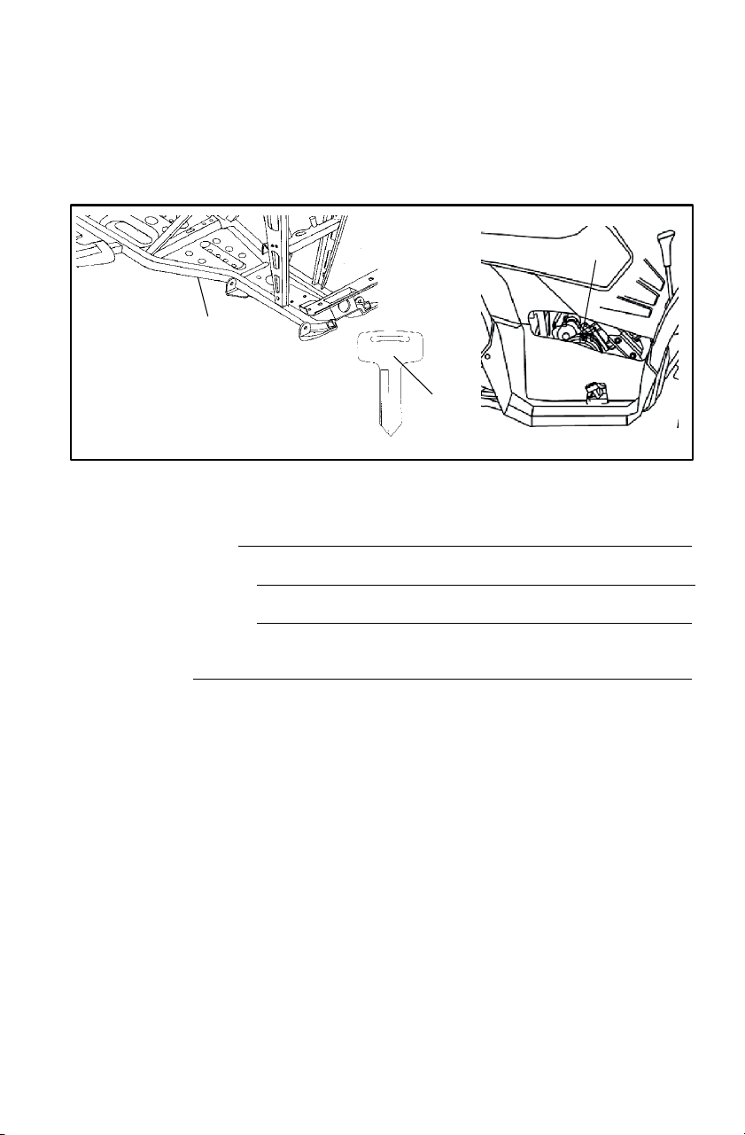
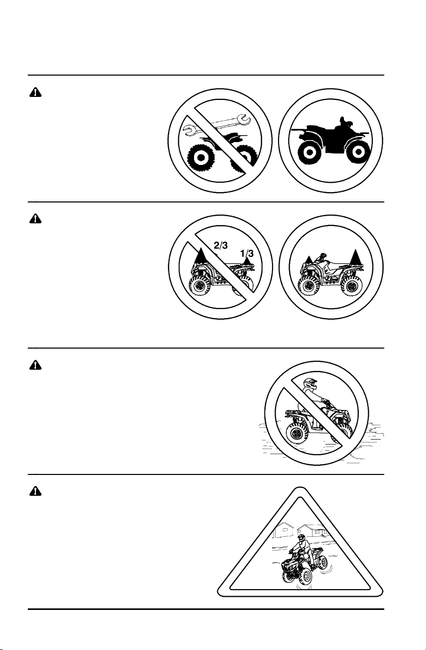
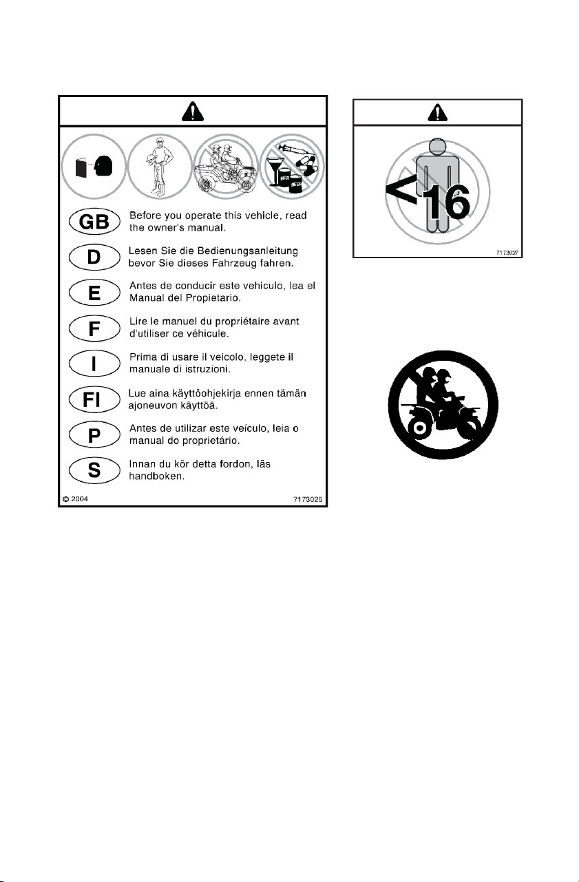
Age Restriction
This vehicle is an ADULT VEHICLE ONLY. Operation is prohibited
for anyone under 16 years of age.

8
SAFETY
Operator Safety
Know Your Vehicle and Riding Area
You are responsible for your personal safety, the safety of others and
the protection of the environment. Read and understand your owner’s
manual. It includes important information about Quadricycle safety.
Ride responsibly. Know all laws and regulations concerning the
operation of this vehicle in your area.
Restrictions
This vehicle is approved for OFF-ROAD TOWING ONLY. Operating
a Quadricycle/trailer combination on public roads is prohibited.
Equipment Modifications
The warranty on your Polaris Quadricycle may be terminated if any
equipment has been added, or if any modifications have been made,
that increase speed or power.
NOTE: The addition of certain accessories, including (but not limited
to) mowers, blades, tires, sprayers and large racks may
change vehicle handling. Use only Polaris-approved
accessories. Know their function and effect on the vehicle.
<
9
SAFETY
Operator Safety
WARNING
Serious injury or death can result if you do not follow the
instructions and procedures listed here and throughout this
manual.
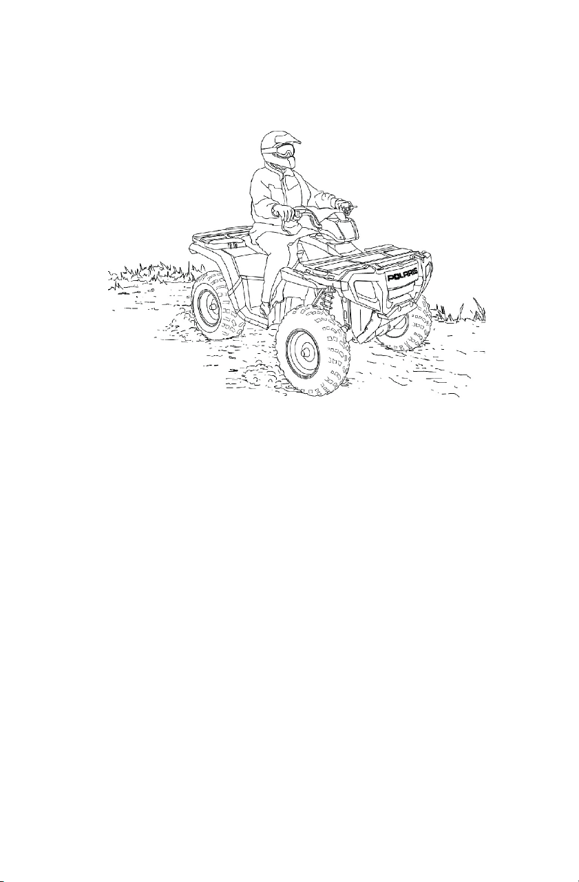
Read and understand all warnings,
cautions and operating procedures
in this manual and on the safety
labels before operating the Quadricycle.
Never operate a Quadricycle without
proper instruction. Take a training
course. Beginners should receive
training from a certified instructor.
Contact an authorized Polaris Quadricycle
dealer or call Polaris at 1-800-342-3764.
Never permit others to operate the Quadricycle unless they have
read and understand this manual and all product labels, and have
completed a certified safety training course.
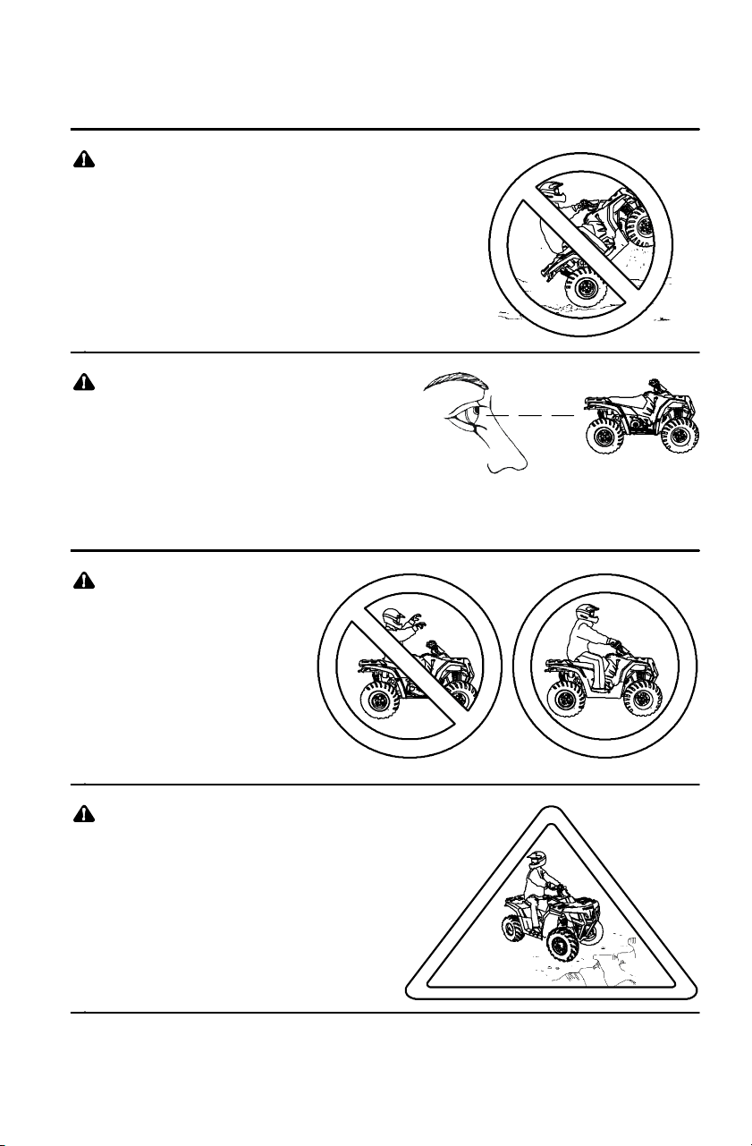
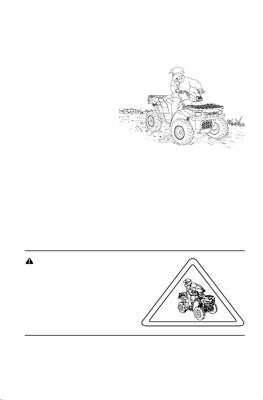
Never allow anyone under 16 years
of age to operate this vehicle.
Never carry a passenger . The
purpose of the long seat is to allow
the operator to shift position.

50
40
0
10
20
30
10
SAFETY
Operator Safety
Always wear an
approved helmet
that fits properly.
Wear eye protection
(goggles or face
shield), gloves,
boots, long
sleeves and long
pants.
Never consume alcohol or
drugs before or while
operating a Quadricycle.
Never operate at
excessive speeds. Travel
and turn at speeds
appropriate for the terrain,
visibility, operating
conditions and your
experience.
11
SAFETY
Operator Safety
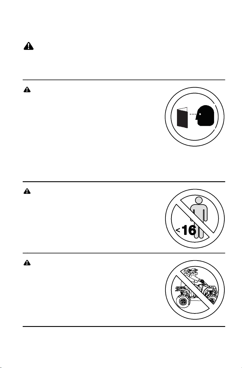
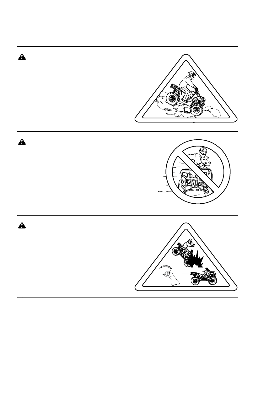
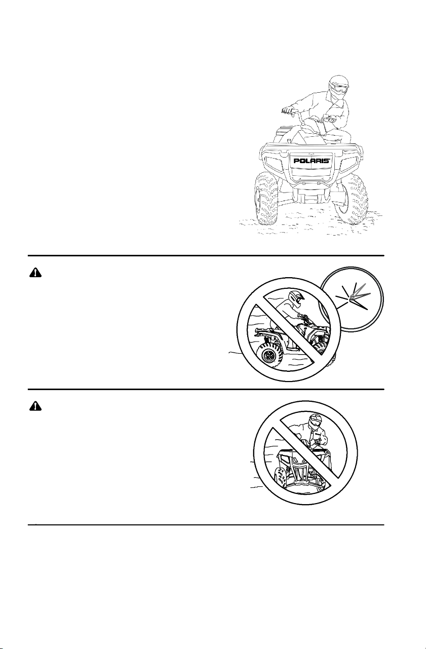
Never attempt wheelies, jumps or
other stunts.
Always inspect your
Quadricycle before each
use to verify that it’s in
safe operating condition.
Follow the inspection and
maintenance procedures
outlined in this manual. See
page 56.
Keep both hands
on the handlebars.
Keep your feet on
the footrests.
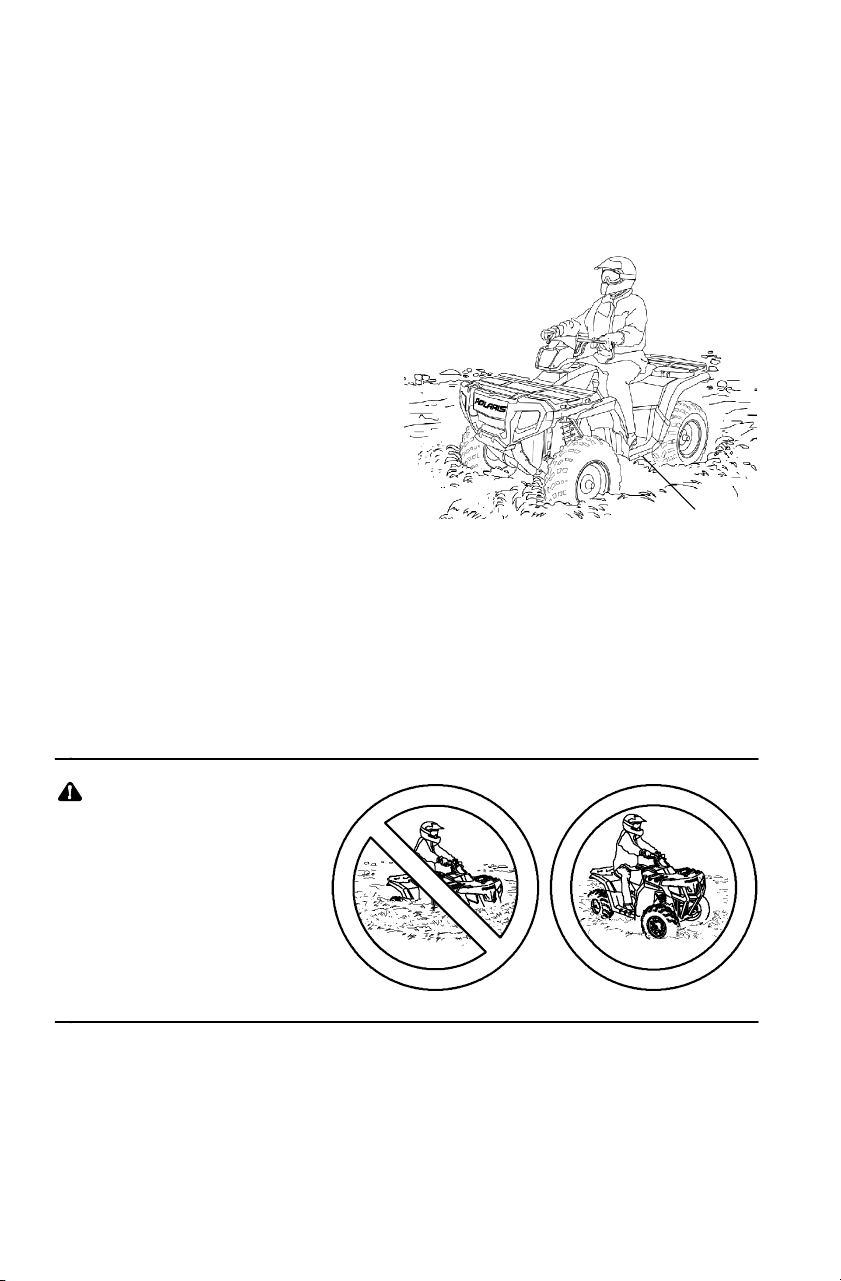
Always travel slowly when
operating on unfamiliar
terrain. Use extra caution.
12
SAFETY
Operator Safety
Use caution when operating
on rough, slippery or loose
terrain.
Always follow the procedures
outlined in this manual for
turning. See page 24.
Never turn sharply at
excessive speeds, which can
lead to vehicle overturn.
If a Quadricycle has been
involved in an accident, always
have an authorized Polaris
dealer inspect the entire vehicle
for possible damage, including
(but not limited to) brake,
throttle and steering systems.

>25_
13
SAFETY
Operator Safety
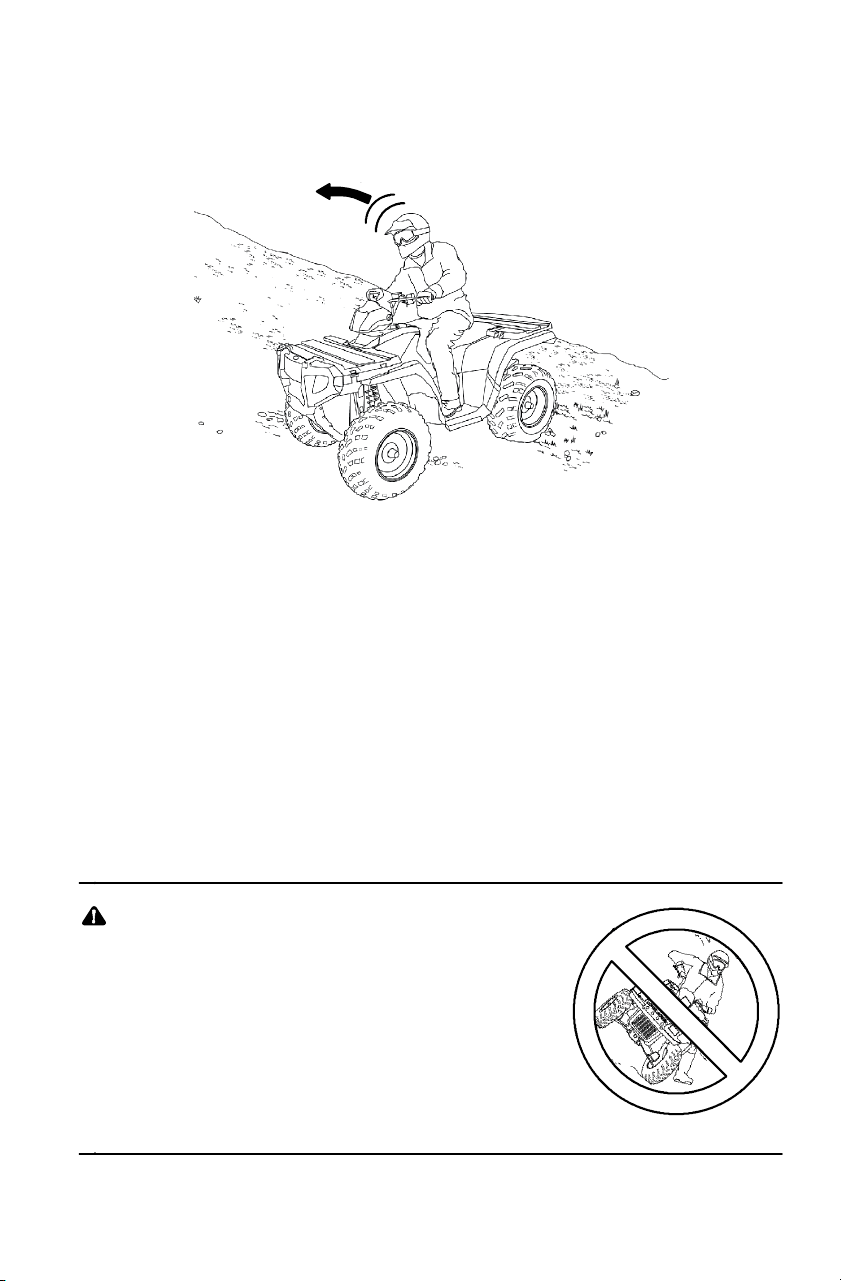
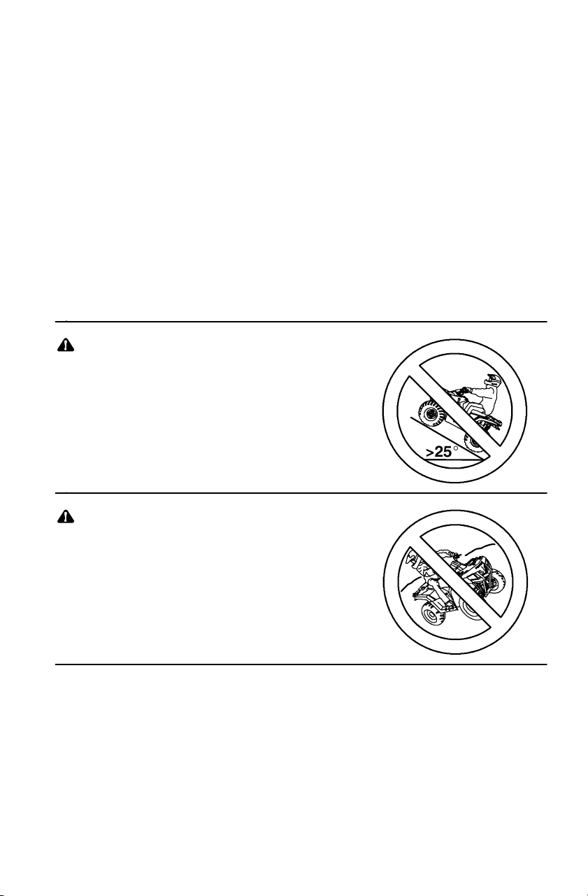
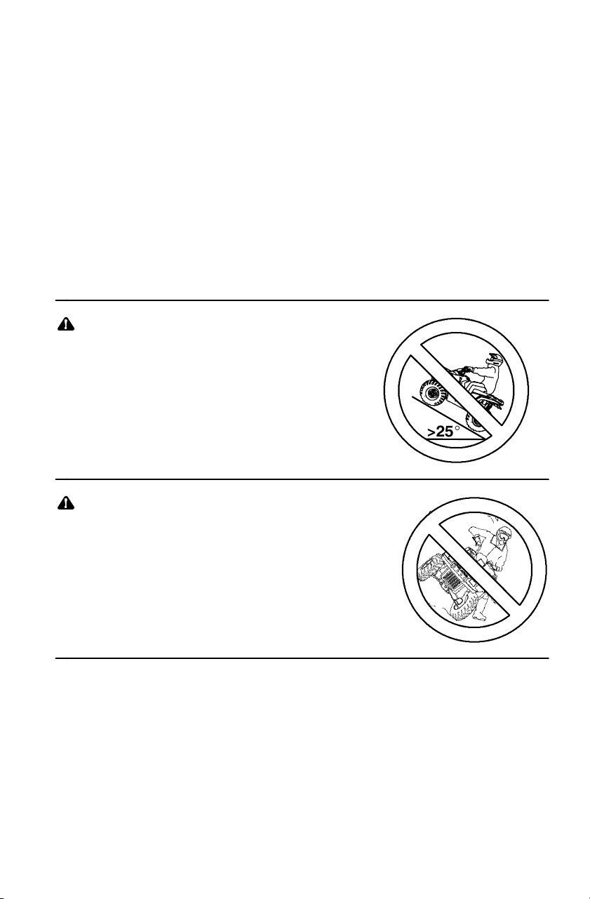
Never operate on hills too
steep for the Quadricycle or for
your abilities. Practice on
smaller hills before attempting
larger hills. Avoid climbing hills
steeper than 25_.
Always follow the procedures
outlined in this manual for
climbing hills. See page 28.
Always follow the procedures
outlined in this manual for driving
downhill and for braking on
hills. See page 32.
Always follow the procedures
outlined in this manual for crossing
the side of a hill. See page 27.
Never attempt to turn the Quadricycle
around on any hill until you’ve
mastered (on level ground) the
turning technique outlined in this
manual.
14
SAFETY
Operator Safety
Always follow the procedures
outlined in this manual for braking if
you stall or roll backwards while
climbing a hill. Never back down a
hill. See page 29.
Always follow the procedures
outlined in this manual for
operating over obstacles.
See page 26.
Always follow the procedures
outlined in this manual for
operating on slippery or loose
surfaces. Use extra caution.
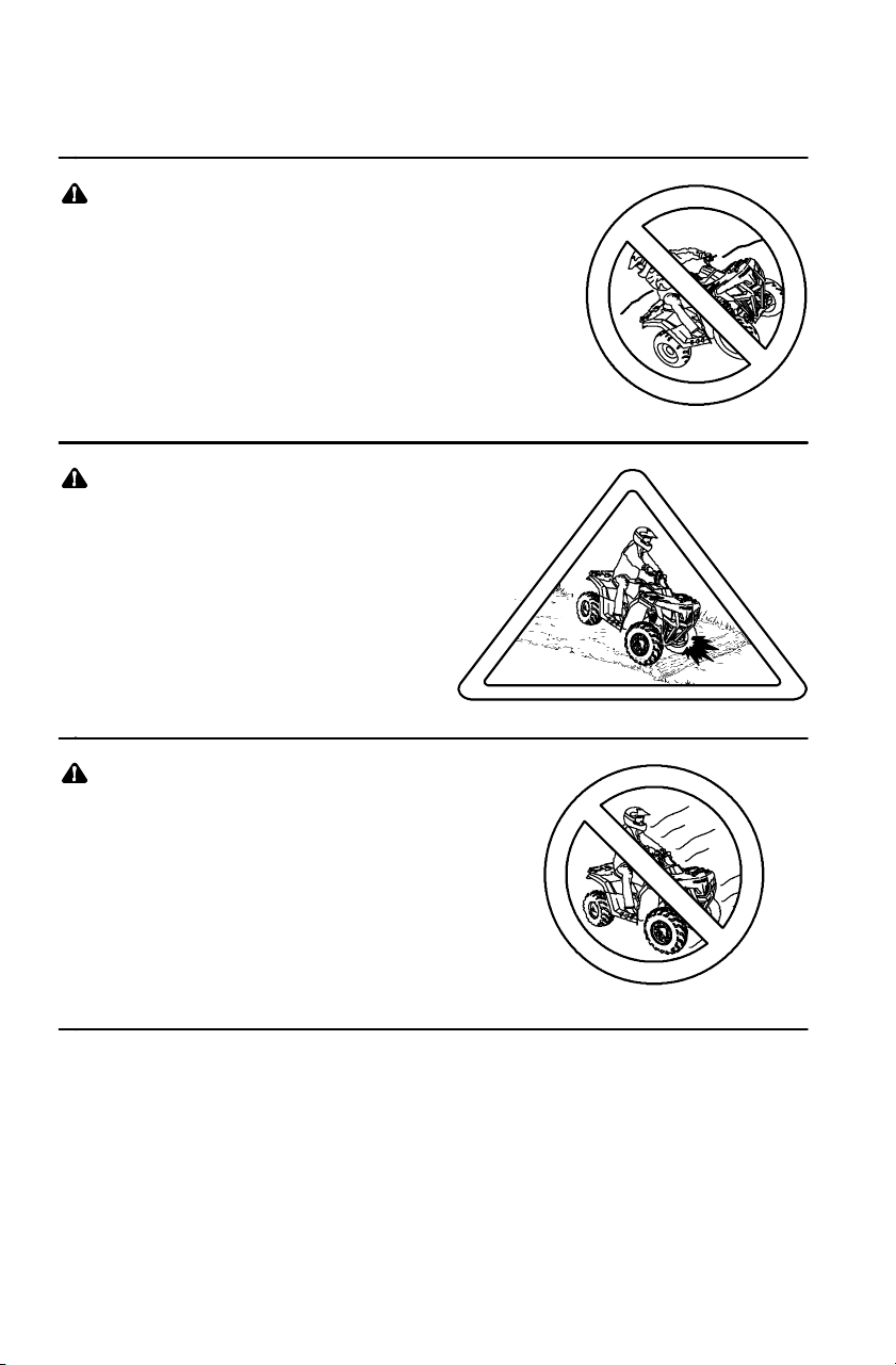
Always avoid skidding or
sliding. See page 25.
15
SAFETY
Operator Safety
Always follow the
procedures outlined
in this manual for
driving through
water. Never drive
through deep or
fast-flowing water .
See page 34.
Always follow the procedures
outlined in this manual for
driving in reverse. See page 33.
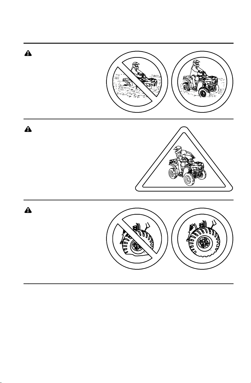
Always use t he size
and type of tires
specified for your
Quadricycle.
Maintain the
proper tire
pressure.
2/3
1/3
2/3
1/3
16
SAFETY
Operator Safety
Never modify a
Quadricycle
through improper
installation or
use of
accessories.
Never exceed the stated
load capacity for your
Quadricycle.
Cargo must be
properly distributed
and securely attached.
Reduce speed and
follow the instructions
in this manual for
carrying cargo or towing.
Allow a greater distance for braking.
Never operate the Quadricycle on
a frozen body of water .
Always use low range when
operating on pavement.
Operating on paved surfaces
may seriously affect the
handling and control of the
Quadricycle and could
result in loss of control,
accident, and/or injury.
Avoid sudden turns or swift
movement of the handlebars.
17
SAFETY
Operator Safety
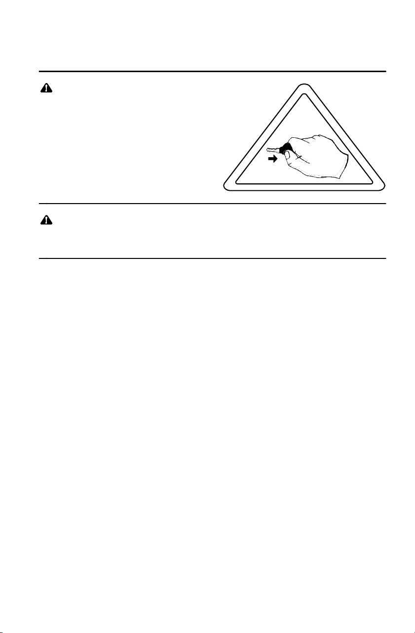
Always remove the ignition
key when the vehicle is not
in use to prevent
unauthorized use or
accidental starting.
Always keep combustible materials away from the exhaust
system. Exposure of combustibles to hot components could
result in a fire.
FOR MORE INFORMATION ABOUT Quadricycle SAFETY,
call Polaris at 1-800 -342-3764.

A
B
C
D
E
F
G
G
18
SAFETY
Safety Decals and Locations
Warning decals have been placed on the vehicle for your protection.
Read and follow the instructions on each decal carefully. If a decal
becomes illegible or comes off, contact your Polaris dealer to purchase
a replacement. Replacement safety decals are provided by Polaris at no
charge. The part number is printed on the decal.
Decal Text
Never operate this vehicle on
hills steeper than 25 degrees.
To prevent flipover on hilly
terrain, when going up or
down, use throttle and brakes
gradually.
A
19
SAFETY
Safety Decals and Locations
B
C
E
D
F
20
SAFETY
Safety Decals and Locations
NO STEP
TIRE PRESSURE IN PSI (KPa):
FRONT 5 (34,5) REAR 5 (34,5)
MAXIMUM WEIGHT CAPACITY (Gross Vehicle Weight)
INCLUDING MACHINE, DRIVER AND CARGO IS 1200 LBS. (546 kg)
Read Owner’ s Manual for more detailed loading information.
7173901
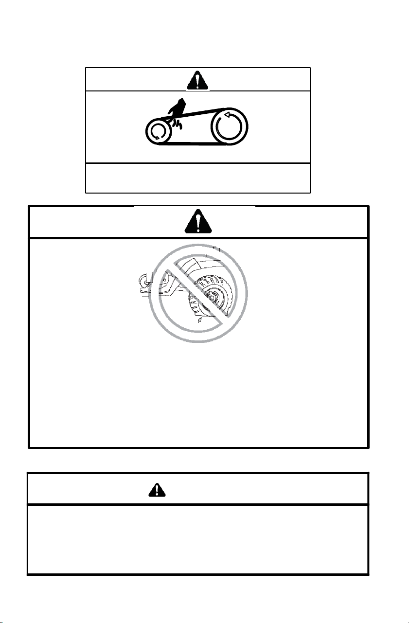
WARNING
DO NOT TOW F ROM RACK OR B UMPER. Vehicle damage or
tipov er may result causing severe injury or death. Tow only f rom
tow hooks or hitc h.
Max Rack Loads: Front 90 lbs. (41 kg) Rear 180 lbs. (82 kg)
7172572
G
21
SAFETY
Safety Decals and Locations
Pushing reverse
override button
may cause
sudden increases
in power and
traction if too much
throttle is applied.
Loss of control or
forward flipover
may result,
especially in AWD.
See Owner’s Manual.
ALL WHEEL
DRIVE
SWITCH
Do not push switch to
engage A WD if the rear
wheels are spinning.
This may cause severe
drive shaft and clutch
damage.
See your Owner’s
Manual.
TRAILER MAX WEIGHT:
1225 LBS. (557 KG) ON LEVEL GROUND
850 LBS. (386 KG) UP TO 15 DEGREE GRADE
HITCH MAX. VERTICAL WEIGHT: 120 LBS. (55 KG)
7170911

1
2
3
4
5
22
SAFETY
Safe Riding Gear
Always wear protective clothing to reduce the chance of injury.
1. Helmet
Always wear a helmet that meets or
exceeds established safety standards. A
helmet can prevent a severe head injury.
2. Eye Protection
Wear shatterproof goggles or a
shatterproof helmet face shield. Use a
lens anti-fogging product to keep them
clean.
3. Gloves
Wear off-road style gloves with knuckle
pads.
4. Boots
Wear strong over-the-calf boots with
heels, like moto-cross boots.
5. Clothing
Wear long sleeves and long pants to protect
arms and legs. Riding pants with kneepads
and a jersey with shoulder pads provide the
best protection. Do not wear loose clothing
that can get entangled in the vehicle, tree
branches or shrubs.
23
SAFETY
Driving Safely
Driving Procedures
1. Sit upright. Keep your feet on the footrests. Keep both hands on the
handlebars.
2. Apply the foot brake.
3. Start the engine and allow it to warm up, then shift the transmission
into gear.
4. Check your surroundings and determine your path of travel.
5. Release the foot brake.
6. Slowly squeeze the throttle lever toward the handlebar to begin
driving. Squeeze the throttle lever further to increase speed.
7. Drive slowly. Practice maneuvering and using the throttle and brakes
on level surfaces.
50
40
0
10
20
30
24
SAFETY
Driving Safely
Making Turns
1. To make a t urn, steer in the
direction of the turn, leaning
your upper body to the inside of
the turn while supporting your
weight on the outer footrest.
Use the same leaning technique
for turning in reverse.
2. Practice turning at slow speeds
before attempting to t urn at
faster speeds.
Never operate at
excessive speeds. Travel
and turn at speeds
appropriate for the terrain,
visibility, operating
conditions and your
experience.
Always follow the procedures
outlined in this manual for
turning. Never turn sharply at
excessive speeds, which can
lead to vehicle overturn.

25
SAFETY
Driving Safely
Driving o n Slippery Surfaces
Whenever driving on slippery
or loose surfaces such as wet
trails, gravel, snow or ice,
follow these precautions:
1. Slow down before driving
onto slippery surfaces.
2. Use extra caution.
3. Be alert. Watch the trail.
Avoid quick, sharp turns.
NOTE: To correct a rear
wheel skid, turn the
handlebars in the
same direction as
the skid and shift
body weight forward.
4. Engage AWD before entering slippery areas.
CAUTION
Severe damage to the drive train may occur if AWD is engaged
while the wheels are spinning. Engage AWD when the wheels
have traction.
Always follow the procedures
outlined in this manual for
operating on slippery or loose
surfaces. Use extra caution.
Always avoid skidding or
sliding.
26
SAFETY
Driving Safely
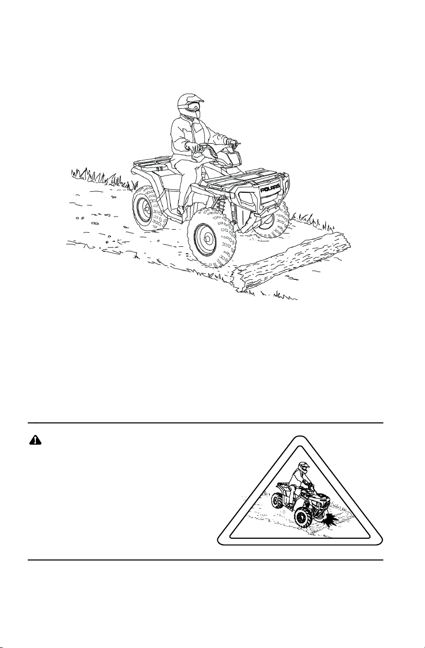
Driving Over Obstacles
1. Always check for obstacles before operating in a new area. Serious
injury or death can result if your vehicle comes in contact with a
hidden obstacle.
2. Be alert. Watch the terrain. Use extra caution.
3. Never operate over large obstacles.
4. Avoid hazards such as logs, rocks and low branches.
Always follow the procedures
outlined in this manual for
operating over obstacles.
27
SAFETY
Driving Safely
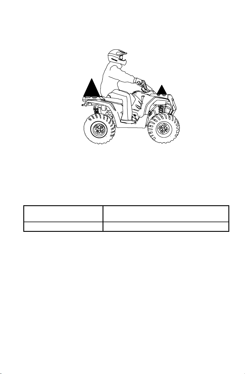
Sidehilling
Avoid crossing the side of a hill (sidehilling) if possible. If sidehilling
is necessary, follow these precautions:
1. Slow down.
2. Avoid hills with excessively slippery or loose surfaces.
3. Shift your weight uphill.
4. Avoid crossing the sides of steep hills.
5. Keep your feet on the footrests.
6. Steer slightly into the hill.
NOTE: If the vehicle begins to tip, quickly turn the front wheels
downhill (if possible) or dismount on the uphill side
immediately!
Always follow the procedures
outlined in this manual for crossing
the side of a hill.
Neverattempttoturnthe
Quadricycle around on any hill until
you’ve mastered (on level ground)
the turning technique outlined in this
manual.

<25_
28
SAFETY
Driving Safely
Driving Uphill
Whenever traveling uphill, follow these precautions:
1. Avoid steep hills (25_ maximum).
2. Check the terrain carefully.
3. Avoid hills with excessively slippery or loose surfaces.
4. Shift your weight uphill.
5. Drive straight uphill.
6. Keep your feet on the footrests.
7. Drive at a steady rate of speed to avoid stalling.
8. Be alert. Be prepared to take emergency action. This may include
dismounting quickly.
9. Never open the throttle suddenly or make sudden gear changes.
10. Never go over the top of a hill at high speed.
>25_
29
SAFETY
Driving Safely
Driving Uphill
If all forward speed is lost:
Keep your weight uphill.
If the vehicle begins rolling downhill, never apply engine power. Never
apply the hand brake while rolling backwards.
Apply the foot brake gradually. When fully stopped, apply the hand
brake as well. Lock the hydraulic parking brake.
Dismount on the uphill side, or to either side if the vehicle is pointed
straight uphill. Turn the vehicle around and remount, following the
procedure described on page 30.
Always follow the procedures
outlined in this manual for
climbing hills. Avoid climbing
hills steeper than 25_.
Always follow the procedures outlined
in this manual for braking if you stall
or roll backwards while climbing a hill.
Never back down a hill.
2.4 m
30
SAFETY
Driving Safely
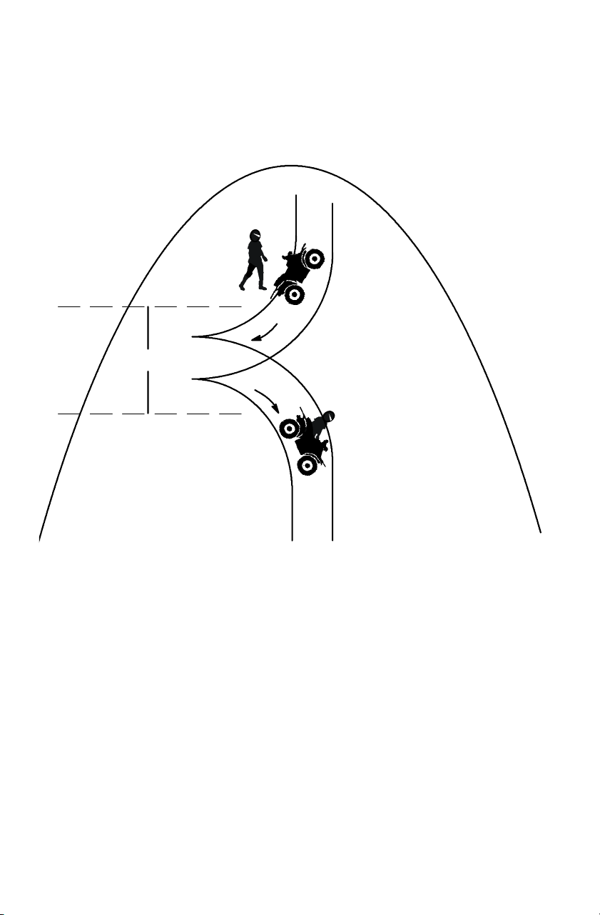
Turning Around on a Hill
If the vehicle stalls while climbing a hill, never back down the hill!
Use the K-turn to turn around.
1. Stop the vehicle. Keep your weight uphill.
2. Lock the hydraulic parking brake.
3. Leave the transmission in forward gear. Turn the engine off.
4. Dismount on the uphill side of the vehicle, or on the left if the
vehicle is pointing straight uphill.
5. Stay uphill of the vehicle and turn the handlebars full left.
6. Squeeze the brake lever to release the parking brake.
7. Slowly release the brake lever and allow the vehicle to roll around
to your right until it’s pointing across the hill or slightly
downward.
>25_
31
SAFETY
Driving Safely
Turning Around on a Hill
8. Lock the hydraulic parking brake. Remount from the uphill side.
Keep your weight uphill.
9. Apply the foot brake.
10. With the transmission still in forward, start the engine.
11. Squeeze and release the brake lever to release the parking brake.
12. Release the foot brake and drive slowly downhill. Control speed
with the foot brake until the vehicle is on level ground.
Always follow the procedures
outlined in this manual for
climbing hills. See page 28.
Always follow the procedures
outlined in this manual for crossing
the side of a hill. See page 27.

50
40
0
10
20
30
32
SAFETY
Driving Safely
Driving Downhill
Whenever descending a hill,
follow these precautions:
1. Check the terrain carefully.
2. Avoid hills with excessively
slippery or loose surfaces.
3. Never go down a hill at high
speed.
4. Slow down.
5. Avoid going down a hill at an
angle, which can cause the
vehicle to pitch sharply to one side.
6. Drive straight downhill.
7. Shift your weight rearward.
8. Apply the foot brake slightly toaidinslowing.
9. Know how to use the hand brake.
Always follow the procedures
outlined in this manual for driving
downhill and for braking on
hills.
Never operate at
excessive speeds. Travel
and turn at speeds
appropriate for the terrain,
visibility, operating
conditions and your
experience.
33
SAFETY
Driving Safely
Driving in Reverse
Follow these precautions when operating in reverse:
1. Avoid backing downhill.
2. Always check for obstacles or
people behind t he vehicle
before backing.
3. Drive slowly.
4. Apply the foot brake
lightly for stopping.
5. Avoid turning at
sharp angles.
6. Never apply the throttle
suddenly.
7. Do not use the override switch unless additional power is required
for vehicle movement. Use with caution.
NOTE: Reverse speed is greatly increased when the override switch
is used. Do not operate at full throttle. Apply just enough
throttle to maintain the desired speed.
CAUTION
Excessive throttle operation while in the speed limit mode may
cause fuel to build in the exhaust, resulting in engine popping
and/or engine damage.
Always follow the procedures
outlined in this manual for
driving in reverse.
1
34
SAFETY
Driving Safely
Driving Through Water
Follow these procedures when operating through water:
1. Check water depth and current before crossing.
2. Avoid operating in
water deeper than the
bottom of the footrests (1).
If it’s unavoidable,
travel slowly, balance
your weight carefully
and avoid sudden
movements. Maintain a
slow and steady forward
motion. Do not make
sudden turns, s tops or
throttle changes.
3. Choose a crossing where
both banks have gradual inclines.
4. Drive slowly.
5. Avoid rocks and obstacles.
6. Wet brakes may have reduced stopping ability. Always test your
brakes after leaving water. If necessary, apply them lightly several
times to allow friction to dry out the pads.
Always follow the
procedures outlined
in this manual for
driving through
water. Never drive
through deep or
fast-flowing water .
35
SAFETY
Driving Safely
Driving Through Water
CAUTION
If the vehicle stops while fully submerged, major engine damage
can result if the machine is not thoroughly inspected. Take the
vehicle to your dealer before starting the engine.
If your vehicle becomes fully immersed, and it’s impossible to take it
to a dealer before starting it, follow the steps described on page 98.
Have the vehicle serviced by your dealer promptly.
NOTE: If water has been ingested into the transmission (PVT),
follow the procedure on page 61.
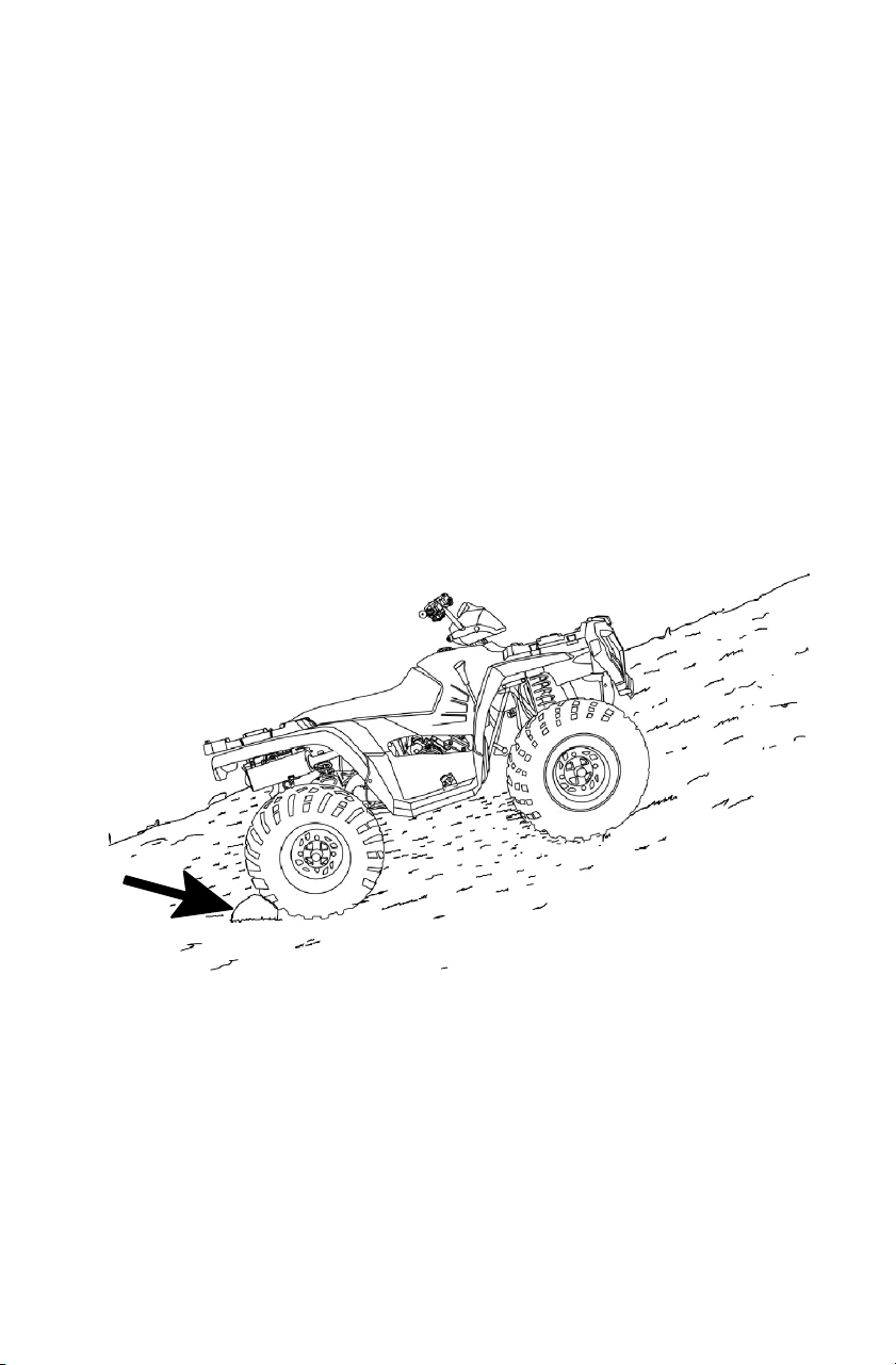
ParkingonanIncline
Avoid parking on an incline. If it’s unavoidable, follow these
precautions:
1. Turn the engine off.
2. Place the transmission in PARK.
3. Always block the rear wheels on the downhill side.
4. Turn the fuel valve off (if equipped).

36
SAFETY
Hauling Cargo and Towin g
WARNING
Overloading the vehicle or carrying or towing cargo improperly
can alter vehicle handling and may cause loss of control or brake
instability. Always follow these precautions when hauling cargo.
S Read and understand the load distribution warnings listed on the
vehicle warning labels.
S Never exceed the stated load capacity for this vehicle.
S REDUCE SPEED AND ALLOW GREATER DISTANCES FOR
BRAKING WHEN HAULING CARGO OR TOWING. Use ex-
treme caution when applying brakes. Avoid situations that re-
quire backing downhill.
S When operating over rough or hilly terrain, reduce speed, cargo
and towed load to maintain stable driving conditions.
S DO NOT BLOCK THE FRONT HEADLIGHT BEAM when
carrying loads on the front rack.
S CARRY LOADS AS LOW ON THE RACK AS POSSIBLE. Car-
rying a load high on the rack raises the center of gravity of the
vehicle and creates a less stable operating condition. Reduce
load weight when cargo is high. Secure off-centered loads that
cannot be centered and operate with extra caution.
S CARRYING A LOAD on only one rack may cause the vehicle to
overturn. Split the load between the front rack and rear rack,
with 1/3 in the front and 2/3 in the back. Do not exceed load ca-
pacities. See specifications beginning on page 112.
S SECURE ALL LOADS BEFORE OPERATING. Unsecured
loads can create unstable operating conditions, which could
result in loss of control of the vehicle.
S OPERATE ONLY WITH STABLE AND SAFELY ARRANGED
LOADS. When handling off-centered loads that cannot be
centered, securely fasten the load and operate with extra
caution. Always attach the tow load to the hitch point
designated for your vehicle.
S USE EXTREME CAUTION when operating with loads that
extend over the rack sides. Stability and maneuverability may
be adversely affected, causing the vehicle to overturn.
S TOWING is approved OFF-ROAD ONLY. Operating a Quadri-
cycle/trailer combination on public roads is prohibited.
S TOWING SPEED should never exceed 16 km/h. Never exceed
8 km/h when towing loads in rough terrain, while cornering, or
while ascending or descending hills.
2/3
1/3
37
SAFETY
Hauling Cargo and Towin g
Load Distribution
To wing
Towing is approved OFF-ROAD ONLY. Operating a
Quadricycle/trailer combination on public roads is prohibited. Do not
exceed the maximum capacities when towing. Do not tow any trailer
on a grade steeper than 15°.
Maximum Towed Load
(Level Ground)
Maximum Vertical Hitch
Weight
386 kg 38.6 kg
(1)
(3)
(4)
(2)
(5)
(2)
38
FEATURES AND CONTROLS
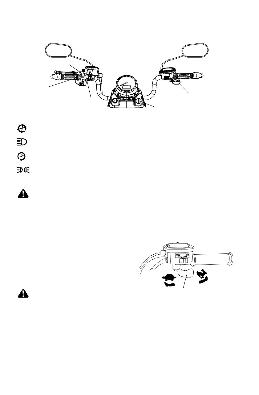
Controls/Instruments
(1) Main Switch
End all electrical power to the vehicle.
LIGHTS ON position turns the headlights on.
Start the engine. The headlights are not on in this position.
After starting the engine, release the key switch t o the POSITION
LIGHTS ON position.
WARNING
Do not attach a large key fob or key ring to the main switch. It
may contact the gas tank cap when turning, causing an
interruption to the electrical system and an unexpected engine
shut-down during operation. This could result in serious injury or
death.
(2) Throttle lever
Press the throttle lever to increase
engine speed and vehicle movement.
Release the lever to reduce engine
speed and vehicle movement.
WARNING
Failure to check or maintain proper operation of the throttle
system can result in an accident if the throttle lever sticks during
operation. Check the lever for proper operation before starting the
engine. Check occasionally during operation.
Do not start or operate a Quadricycle with sticking or improperly
operating throttle controls.
Contact your dealer for repair if throttle problems arise.
(4)
(3)
(5)
39
FEATURES AND CONTROLS
Controls/Instruments
(3) Engine Stop Switch
OFF
RUN
The engine will not start or run when the
switch is i n the OFF position.
(4) Light Switch
High Beam
Low Beam
The lights do not operate unless the main key switch is on and the
engine stop switch is in the RUN position.
(5) Speedometer Mode/Override Switch (Reverse Speed Limiter)
Press the button to toggle t hrough the speedometer display modes
(except in reverse). See page 52.
To gain additional power while operating in reverse, cancel the reverse
speed limit function by pressing the override switch before opening the
throttle.
NOTE: The override switch also allows activation of AWD in reverse
if the AWD switch is on.
WARNING
Activating the override switch with the throttle open and while
operating in reverse can cause loss of control. Do not activate
the override switch while the throttle is open.
(11)
(8)
(12)
(10)
(13)
(14)
(6)
(9)
(7)
(8)
(7)
40
FEATURES AND CONTROLS
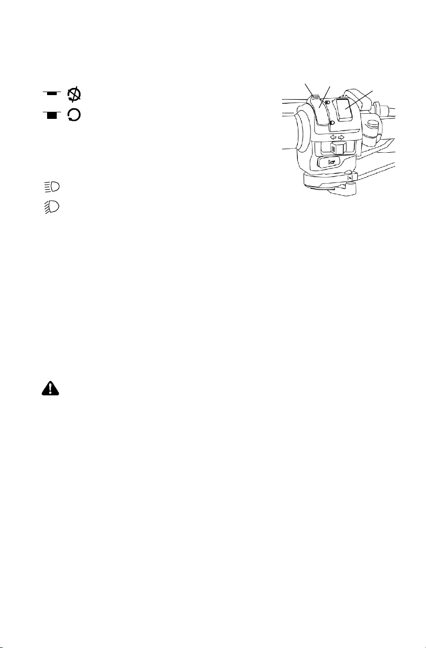
Controls/Instruments
(6) Mirrors
Use the mirrors to assist in traffic maneuvers. Always check and adjust
the mirrors before driving the Quadricycle.
(7) All Wheel Drive (AWD) Switch
See page 45 for AWD operating procedures.
(8) Electronic Throttle Control (ETC)
ETC causes the engine to stop if
the throttle cable sticks in an
open position when the operator
releases the throttle lever.
WARNING
The Electronic Throttle Control (ETC) stops the engine in the
event of a throttle system malfunction. Do not modify the ETC
system or replace it with other throttle mechanisms.
(10)
(11)
(9)
(12)
(13)
(14)
41
FEATURES AND CONTROLS
Controls/Instruments
(9) Turn Signal Indicator
View certain vehicle functions on
the instrument panel. The
corresponding lights illuminate
when the feature is activated.
(10) Hazard W arning
Push the hazard warning
switch to cause all turn
indicators to flash simultaneously.
Use this feature to alert others of an emergency or other situation
requiring caution.
(11) Choke (if equipped)
The choke assists in starting a cold engine. See page 57.
(12) Horn
Press the horn button to alert others
of your presence.
(13) Turn Signal
Push the toggle switch either left or
right to activate the corresponding
turn signal. Return the toggle to the
center position and push it inward to
end the signal.
(14) Rear Brake Lever
The brake lever operates the rear
brakes only. See page 42.
42
FEATURES AND CONTROLS
Brakes
Foot Brake
The all-wheel foot brake is located
on the right footrest. The foot brake
operates both front and rear brakes.
Press the brake pedal down with
your foot to engage the all-wheel
brakes.
Rear Brake Lever
The left brake lever operates the
hydraulic rear brakes only.
Squeeze the brake lever toward
the handlebar to apply the rear
brakes.
If the rear wheels begin to skid or slide
while using this brake, reduce lever
pressure.
WARNING
Aggressively applying the rear brake when backing down a hill
may cause rear tipover.
Aggressively applying the rear brake while moving forward may
cause the rear wheels to skid and result in loss of control.
Read this owner’s manual and understand the operation of all
brake systems on this vehicle.
Always use caution whenever applying only the rear brakes.
43
FEATURES AND CONTROLS
Brakes
Parking Brake
WARNING
Operating the Quadricycle while the parking brake is engaged
could result in an accident and serious injury or death. Always
check to be sure the parking brake is disengaged before
operating.
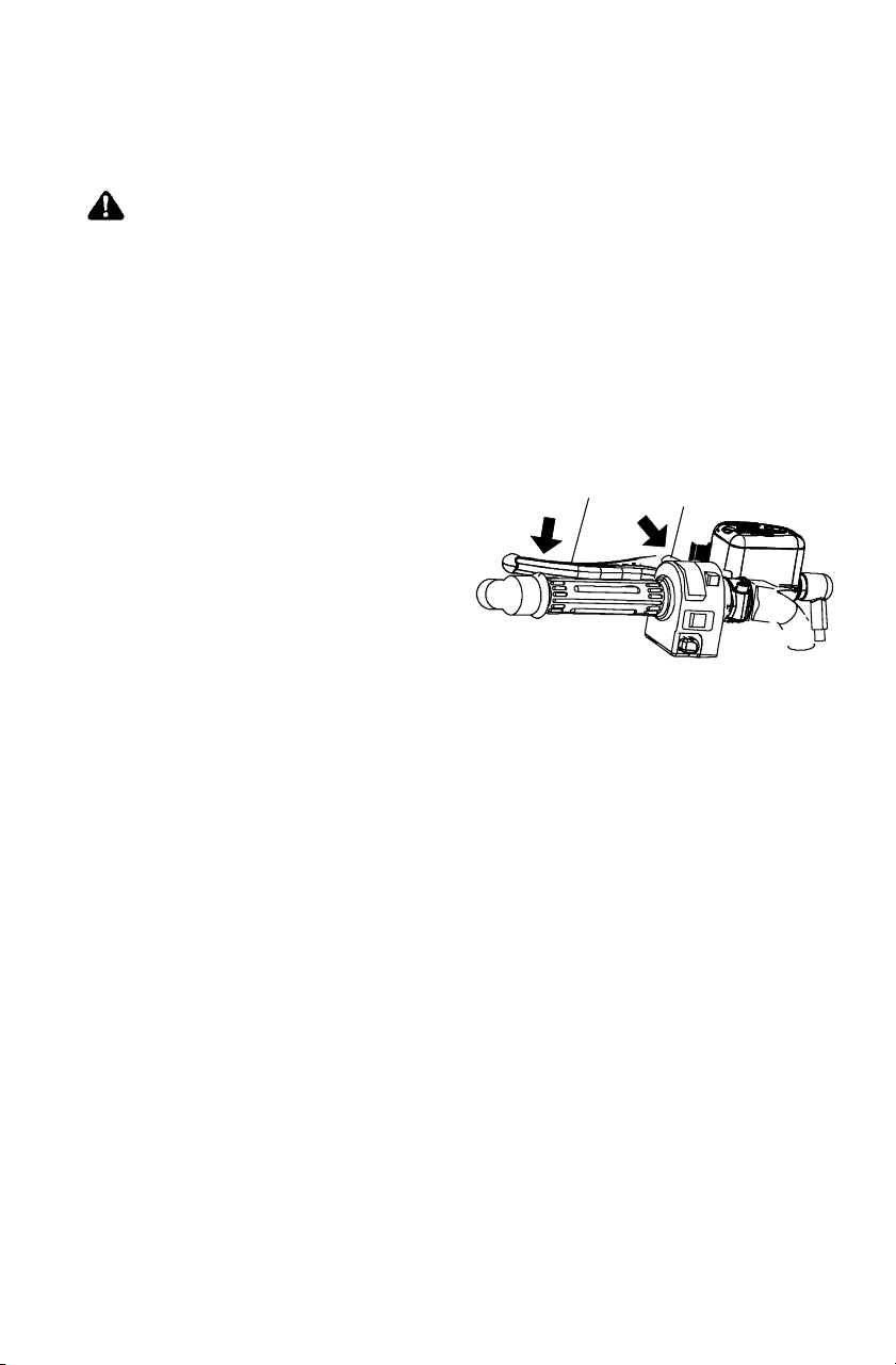
Locking the Parking Brake
The hydraulic parking brake lock is a temporary l ock. Do not rely on
the hydraulic parking brake when leaving the vehicle unattended.
Always place the transmission in PARK.
1. Place the transmission in PARK.
2. Squeeze the left brake
lever (1).
3. Move the park brake lock (2)
to the locked position.
This will prevent the lever
from returning to the
released position.
4. To release the parking brake lock, squeeze and release the brake
lever. The parking brake will release automatically.
1
2
44
FEATURES AND CONTROLS
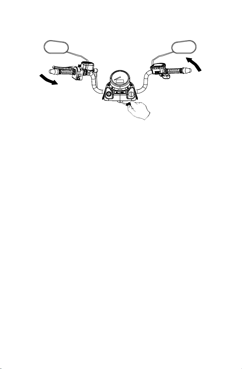
Steering Lock
Lock the steering to prevent unauthorized use or theft of the vehicle.
1. Turn the handlebars to the full left position.
2. Insert the steering lock key and turn it clockwise.
3. Remove the key.
4. Reverse the procedure to unlock the steering.
NOTE: Place the steering lock keys in a safe place. The lock must
be replaced if the keys are lost.
45
FEATURES AND CONTROLS
AWD Operation
The AWD switch may be turned on or off while the vehicle is moving.
AWD will not engage until engine speed is below 3100 RPM. AWD
remains engaged until the switch is turned off. There is no limit to the
length of time the vehicle may remain in AWD.
If the switch is turned off while the front gearcase is engaged, it will
not disengage until the rear wheels regain traction. Engage AWD
before getting into situations where maximum traction is needed. If
the rear wheels are spinning, release the throttle before switching to
AWD.
CAUTION
Switching to AWD while the rear wheels are spinning may cause
drive shaft and gearcase damage. Switch to AWD while the rear
wheels have traction or are at rest.
NOTE: The override switch allows activation of AWD in reverse if the
AWD switch is on. See page 39.
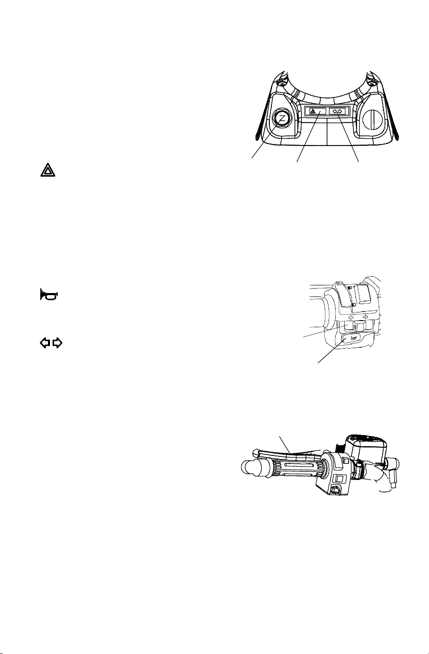
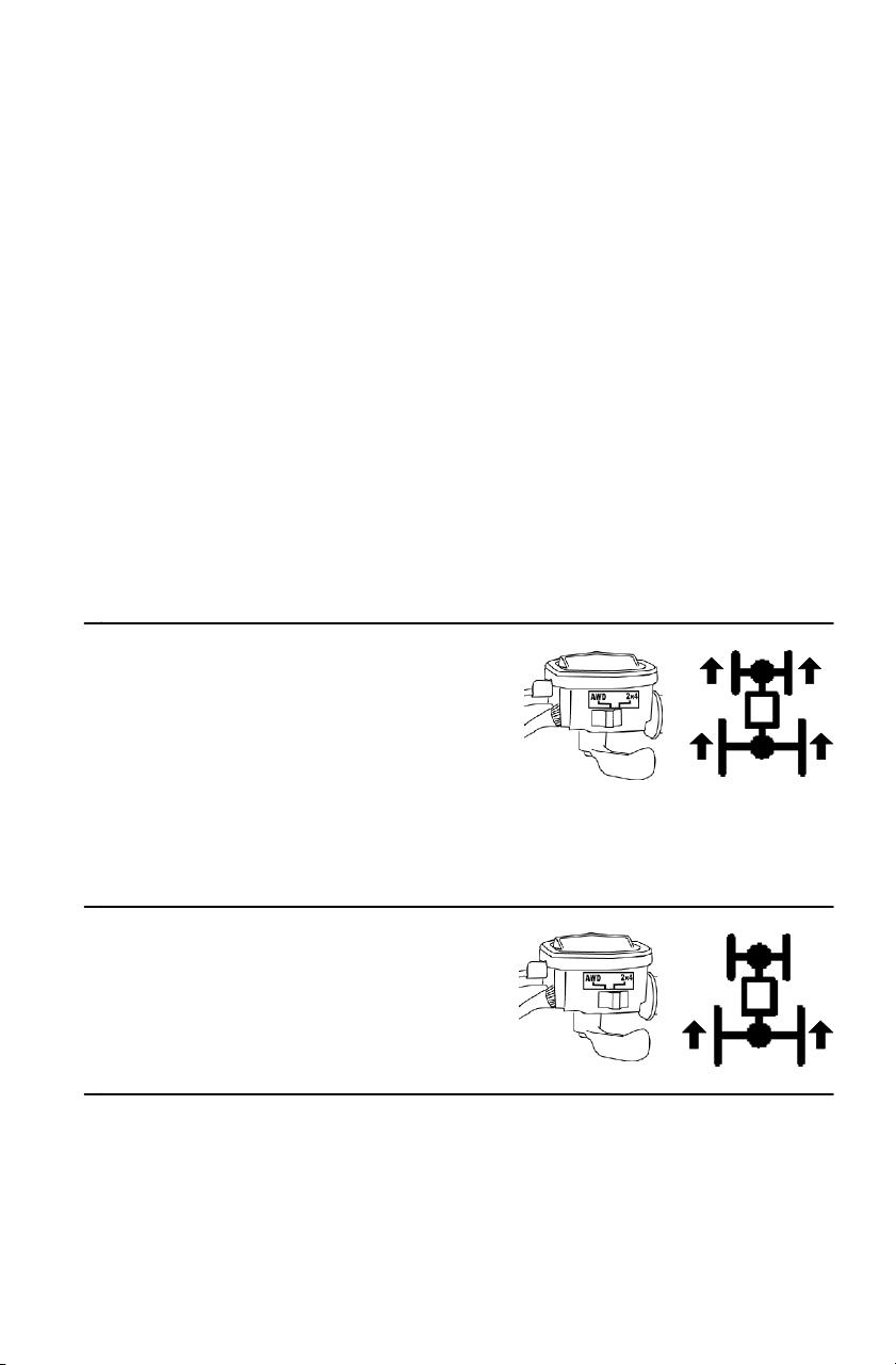
AWD
When the AWD switch is on, the
Quadricycle is in four-wheel drive
and the differential is locked,
providing maximum traction. The
front gearcase automatically
engages when the rear wheels lose traction.
When the rear wheels regain traction, the front gearcase automatically
disengages.
2X4
When the 2X4 switch is on, the
Quadricycle is in two-wheel
drive at all times and the
differential is l ocked.

46
FEATURES AND CONTROLS
Fuel Safety
WARNING
S Gasoline is highly flammable and explosive under certain
conditions.
S Use extreme caution whenever handling gasoline.
S Refuel with the engine stopped. Refuel outdoors or in a well
ventilated area.
S Never fill a fuel container while it’s on the vehicle. Static
electricity between the rack and container could cause a spark.
S Do not smoke or allow open flames or sparks in or near the
area where refueling is performed or where gasoline is stored.
S Do not overfill the tank. Do not fill the tank neck.
S If gasoline spills on your skin or clothing, immediately wash it off
with soap and water and change clothing.
S Turn the fuel valve off (if equipped) whenever the vehicle is
stored or parked.
47
FEATURES AND CONTROLS
Fuel Tank
The fuel tank filler cap is located directly
below the handlebar. The gauge in the cap
shows the approximate amount of fuel
remaining. Refuel with either leaded or
unleaded gasoline with a minimum of 87
octane.
Fuel Filter (EFI)
The in-line fuel filter should be replaced by your dealer after every 200
hours of operation and any time the fuel becomes contaminated with
dirt or debris. Do not attempt to clean the fuel filter.
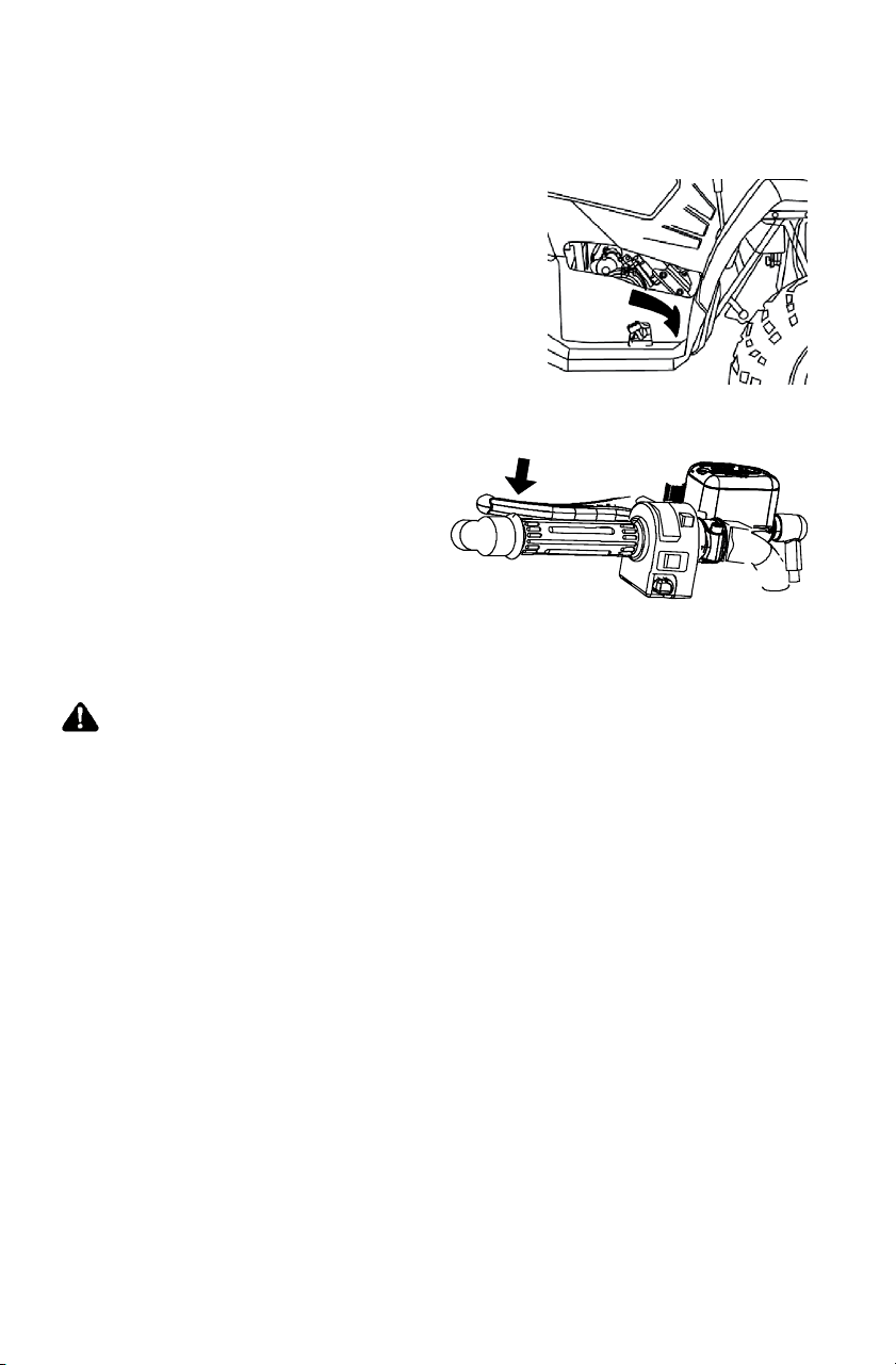
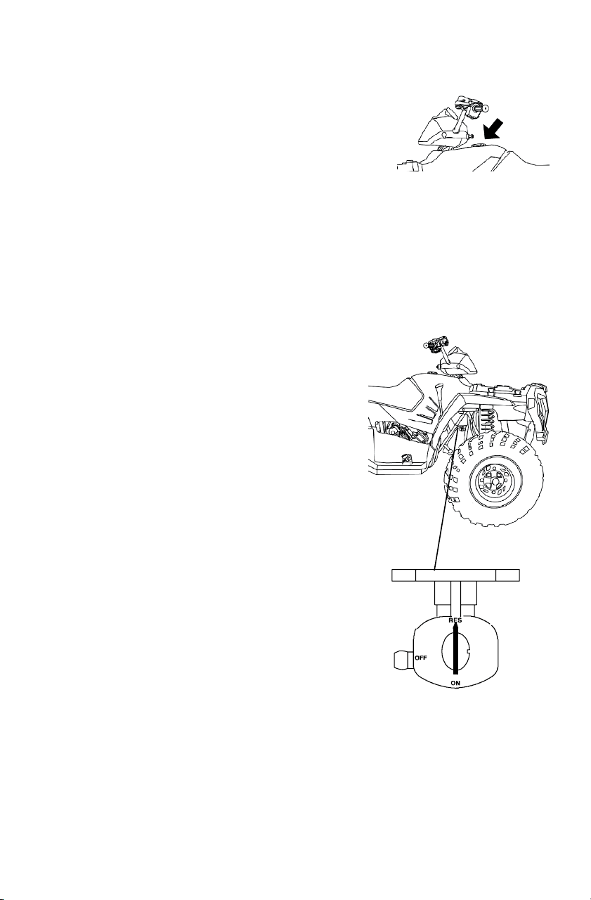
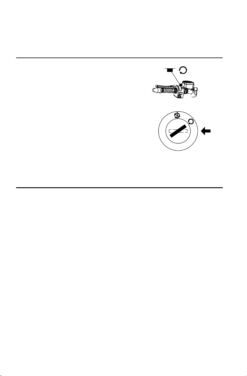
Fuel Valve (if equipped)
The fuel valve is located on the bottom of
the fuel tank. Access the fuel valve
through the right front wheel well.
OFF: For vehicle storage and when
transporting.
RES: For normal operation.
ON: Not used on this model.
NOTE: This vehicle is equipped
with a digital fuel gauge
that will indicate a low fuel
condition. Refuel when the
gauge indicates a low fuel
condition.

H
N
P
L
R
48
FEATURES AND CONTROLS
Transmission Gear Selector
The transmission gear selector
is located on the right side of
the vehicle. Whenever the
vehicle is left unattended, place
the transmission in PARK. The
transmission is locked when it’s
in PARK.
H: High Gear
L: Low Gear
N: Neutral
R: Reverse
P: Park
CAUTION
Shifting gears with the engine speed above idle or while the
vehicle is moving can cause transmission damage. Stop the
vehicle, release the throttle and move the shift lever to the
desired gear. See your dealer if you experience any shifting
problems.
Belt Life
To exte nd belt life, use low for wa rd gear in heavy pulling situations and
when operating at less than 11 km/h for exte nded periods of time.
If towing the vehicle is necessary, shift the transmission into neutral for
better mobility and to prevent damage to the belt.

49
FEATURES AND CONTROLS
Recoil Starter (if equipped)
If the battery is too weak to start
the engine, use the recoil starter (1).
Follow the starting procedures on
pages 57 and 59, cranking the
engine with the recoil starter
instead of the main key switch.
1. Grasp the recoil starter rope
handle tightly. Pull slightly
until the starter mechanism
engages.
2. Pull the rope abruptly to start the engine.
CAUTION
Extending the starter rope too far will cause damage to the recoil
assembly. Do not extend the starter rope so far that it stops.
If the starter rope handle is not seated properly, water may enter
the recoil housing and damage components. Make sure the
handle is fully seated on the recoil housing, especially when
traveling in wet areas.
1
50
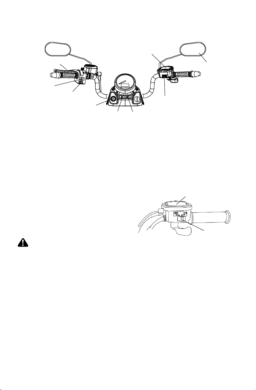
FEATURES AND CONTROLS
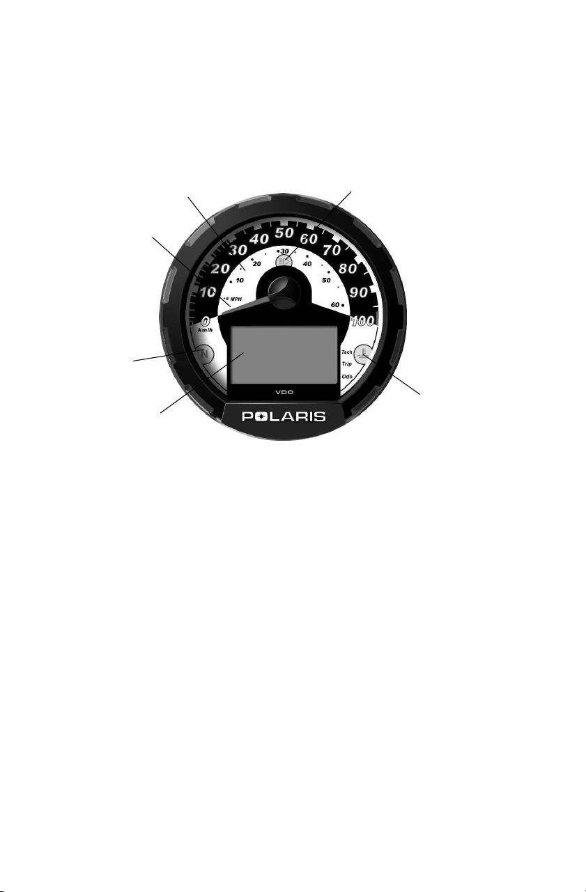
Instrument Cluster
The instrument cluster senses vehicle speed from the right front wheel.
It measures distance as well as hours of operation. It also includes a
reverse speed limiter function that limits reverse speed to about 11-14
km/h. See page 39 for additional information.
1. Rider Information Center
2. Neutral Indicator
3. Speedometer needle (In addition to showing vehicle speed, the
needle flashes when a warning condition exists.)
4. Speedometer
5. High Beam Indicator
6. Hot Engine Indicator
CAUTION
To prevent damage to the instrument cluster, wash the
Quadricycle by hand or with a garden hose using mild soap.
Do not use alcohol to clean the instrument cluster.
Immediately wash off any gasoline that splashes on the
instrument cluster.
3
4
1
5
2
6
7
5
4
3
1
6
2
8
51
FEATURES AND CONTROLS
Instrument Cluster
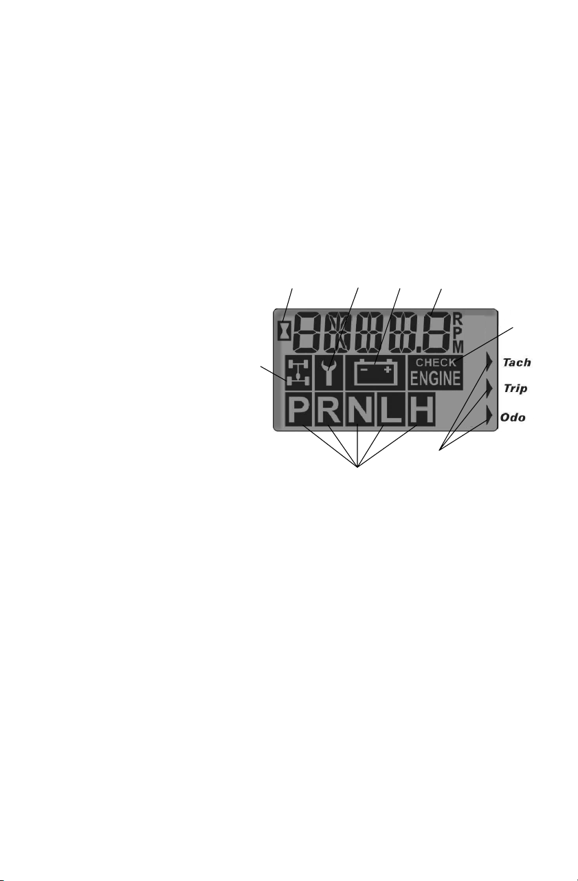
Rider Information Center
The rider information center is located in the instrument cluster. All
segments will light up for 2.5 seconds at start-up.
NOTE: If the instrument cluster fails to illuminate, a battery
over-voltage condition may have caused it to shut down to
protect the electrical system. If this occurs, take the
Quadricycle to your Polaris dealer .
1. Gear Indicator - As the shift lever is moved, this indicator shows
the gear the transmission is in.
H = High Range
L = Low Range
N = Neutral
R = Reverse
P=Park
2. AWD Indicator - This
indicator illuminates
when the electrical
portion of the AWD
system is enabled.
3. Engine Hour Display Indicator
4. Service Interval/Diagnostic Mode Indicator
5. Low Battery and Over-Voltage - This warning usually indicates
that the vehicle is being operated at an R PM too low to keep the
battery charged. The war ning may also occur if the engine is at idle
and a high electrical load (lights, cooling fan, accessories) is applied.
Drive at a higher RPM or recharge the battery to clear the warning.
6. Odometer/Tachometer/Tripmeter/ Hour Meter
7. Check Engine Warning Indicator - “HOT” will display when the
engine is overheating. Turn off the engine or serious damage could
result.
8. Mode Indicator

52
FEATURES AND CONTROLS
Instrument Cluster
Rider Information Center
The reverse override button on the left handlebar is also the mode
button. Use the m ode button to t oggle through the four (4) s tandard
modes of the rider information center.
NOTE: The transmission cannot be in reverse.
Mode 1 - Odometer
The odometer records the total distance traveled by the vehicle since
manufacture.
Mode 2 -Trip Meter
The trip meter records the distance traveled on each trip if it’s reset
before each trip. To reset the trip meter , select the trip meter mode.
Press and hold the mode button (override button) until the total
changes to 0.
NOTE: The trip meter displays a decimal point, but the odometer
does not.
Mode 3 - Hour Meter
The hour meter logs the total hours the engine has been in operation.
Mode 4 - Tachometer
The tachometer displays engine RP M. Small fluctuations in the RPM
are normal due to changes in humidity, temperature and elevation.

53
FEATURES AND CONTROLS
Instrument Cluster
Rider Information Center
Diagnostic Mode
The diagnostic mode is for informational purposes only. Please return
your Quadricycle to your dealer for all major repairs.
The wrench icon will display when the gauge is in the diagnostic
mode.
Steps to enter the diagnostic mode:
1. Turn the main key switch off and wait 10 seconds.
2. Shift the transmission into neutral or park.
3. Hold the mode button and turn the main key switch on.
4. Release the switch as soon as the display is activated.
5. Use the mode button t o toggle through the six (6) diagnostic
screens.
Three (3) ways to leave the d iagnostic mode:
S Shift the transmission out of neutral.
S Turn the main key switch off and on.
S Move the tires.
Screen 1: Battery voltage
Screen 2: Tachometer
Screen 3: AWD diagnostic
This screen indicates whether or not current is flowing through the
AWD system.
Screen 4: Gear circuit diagnostic
This screen displays the resistance value (in ohms) being read at the
gear switch input.

54
FEATURES AND CONTROLS
Instrument Cluster
Rider Information Center
Diagnostic Mode
Screen 5: Programmable service interval
The programmable service interval provides a convenient reminder
when routine maintenance is due. This feature is pre-set at 50 hours.
You m ust enable the programmable service interval before it can be
used.
When set, the hours of operation are subtracted from the set hours until
0 is reached. The wrench icon will flash quickly for five seconds each
time the engine is started as a reminder that service is due.
Setting the Service Interval
1. Press and hold the mode/override button until the wrench icon
flashes. Release the button.
2. Press the button once to advance t he setting by one hour. Press and
hold the button to advance the hours at a faster pace.
3. When the desired time increment is displayed, release t he button.
When the wrench stops flashing, service hours are set.
NOTE: If you scroll past the intended number, hold the button down
until the count turns over to 0. You can then reset the
number .
Disabling the Service Interval
1. Toggle to the service interval mode.
2. Press and hold the mode button for approximately seven (7)
seconds. The service interval is disabled when the word OFF
displays.
Screen 6: Miles/Kilometers toggle
The display in the tripmeter and odometer can be changed to display
either kilometers or miles. The current display mode will be shown as
either KM or MP.
1. Press and hold the mode button until the letters flash.
2. Press and release the mode button once. When the display stops
flashing, the mode has been set.

55
OPERATION
Break-In Period
The break-in period for your new Polaris Quadricycle is the first ten
hours of operation, or the time it takes to use the first two full t anks of
gasoline. No single action on your part will increase the life and
performance of your Quadricycle more t han following the procedures
for a proper break-in. Careful treatment of a new engine and drive
components will result in more efficient performance and longer life
for these components.
Do not operate at full throttle or high speeds for extended periods
during the first three hours of use.
Engine and Drivetrain Break-in
1. Fill the fuel tank with the recommended fuel.
2. Check the oil level on the dipstick. Add oil if necessary.
Seepage69.
3. Select an open area that allows room to familiarize yourself with
vehicle operation and handling.
4. Drive slowly. Vary throttle positions. Do not operate at sustained
idle.
5. Perform regular checks on fluid levels, controls and areas outlined
on the daily pre-ride inspection checklist. See page 56.
6. Pull only light loads.
7. Perform the break-in oil change at one month.
PVT Break-in (Clutches/Belt)
Break in the clutches and belt by operating at slower speeds during t he
break-in period as recommended. Pull only light loads. Avoid
aggressive acceleration and high speed operation during the break-in
period.

56
OPERATION
Pre-Ride Inspection
Pre-Ride Checklist
Item Remarks See
Page
Brake system / lever travel Ensure proper operation 82
Brake fluid Ensure proper level 80
Foot brake Ensure proper operation 42
Front suspension Inspect, lubricate if necessary 67
Rear suspension Inspect, lubricate if necessary 67
Steering Ensure free operation --
Tires Inspect condition and pressure 90,112
Wheels / fasteners Inspect, ensure fastener tightness 89
Frame nuts, bolts, fasteners Inspect, ensure tightness --
Fuel and oil Ensure proper levels 47, 69
Throttle Ensure proper operation 38, 86
Indicator lights / switches Ensure operation 38
Engine stop switch Ensure proper operation 39
Air filter, pre-filter Inspect, clean 91
Air box sediment tube Drain deposits whenever visible --
Headlamp Check operation, apply Polaris dielec-
tric grease when lamp is replaced
92
Brake light / tail lamp Check operation, apply Polaris dielec-
tric grease when lamp is replaced
93
Riding gear Wear helmet, goggles, protective
clothing
22
57
OPERATION
Starting the Engine
Starting a Cold Engine
WARNING
Engine exhaust contains poisonous carbon monoxide and can
cause loss of consciousness resulting in serious injury or death.
Never run an engine in an enclosed area or indoors.
CAUTION
Operating the vehicle immediately after starting could cause
engine damage. Allow the engine to warm up for several minutes
before operating.
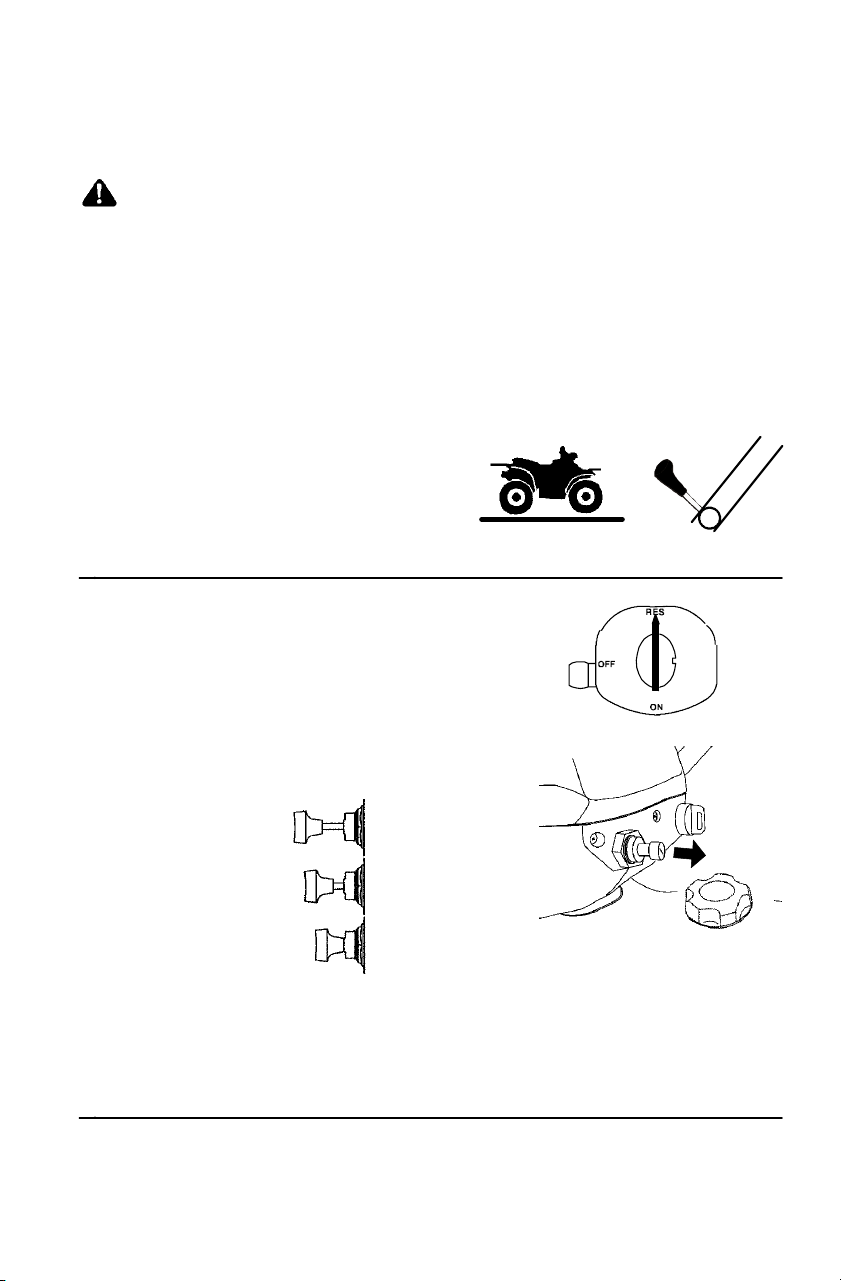
1. Position the vehicle on a
level surface.
2. Place the transmission in
PARK.
Sportsman 500 (Carbureted Model)
3. Turn the fuel valve to “RES”.
4. Pull the choke knob out until it stops.
NOTE: Make sure the choke is off during
operation. Excess fuel washing
into the engine oil will increase
wear on engine components.
FULL ON
HALF ON
OFF
NOTE: If the engine slows or stops after starting, position the choke
knob half way in. Vary engine RPM slightly with the throttle.
When the engine idles smoothly, push the choke all the way
in.
H
N
P
L
R
58
OPERATION
Starting the Engine
Starting a Cold Engine
All Models
5. Move the engine stop
switchtoRUN.
NOTE: Do not press the throttle
while starting the engine.
6. Turn the ignition key past the ON
position to engage the starter.
Activate the starter for a
maximum of five seconds,
releasing the key when the engine
starts.
7. If the engine does not start, release the
starter and wait five seconds.
8. Repeat steps 6 and 7 until the engine starts.

59
OPERATION
Starting the Engine
Starting a Warm Engine (Carbureted Models)
Warm engines do not normally require the use of the choke.
Over-using the choke can cause spark plug fouling.
1. Start a warm engine using the same procedure for starting a cold
engine, but do not use the choke. See page 57.
NOTE: If the engine has cooled and does not readily start,
intermittent use of the choke (pulled half way out) may be
necessary.
2. If the engine is over-choked when warm, push in the choke and
depress the throttle lever fully while cranking.
3. Release the throttle lever immediately after the engine starts.
4. If the engine does not start and all conditions are favorable, change
the spark plug and try again.
Cold Weather Operation for 4-Cycle Engines
Internal engine condensation increases as outside temperatures
decrease. If the vehicle is used year-round, check the oil level
frequently. A rising oil level could indicate condensation in the bottom
of the oil tank, which can lead to engine damage. Any condensation
must be drained.
Always operate the engine long enough to reach operating temperature,
which reduces condensation. See your Polaris dealer for engine heater
kits, which provide quicker warm-ups and easier starting i n cold
weather.

60
OPERATION
Polaris Variable Transmission
Preventing Belt Slip / Failure
Belt slip creates heat that destroys belts and causes outer clutch covers
to fail. Switch to low range when operating at slow speeds. The air
temperature in the clutch cover will be greatly reduced, i ncreasing t he
life of the PVT components (belt, cover, etc.).
When To Use Low Range and High Range
Use low range for:
S Heavy pulling
S Driving in rough terrain (swamps, mountains, etc.) at slow speeds
S Driving on pavement
Use high range for:
S Driving off road at faster speeds

61
OPERATION
PVT System
WARNING
Do not modify any component of the PVT system. Doing so may
reduce its strength so that a failure may occur at a high speed.
The PVT system has been precision balanced. Any modification
will cause the system to be out of balance, creating vibration and
additional loads on components.
The PVT system rotates at high speeds, creating large amounts
of force on clutch components. Extensive engineering and
testing has been conducted to ensure the safety of this product.
However , as the owner, you have the following responsibilities to
make sure this system remains safe:
S Always follow all recommended maintenance procedures. See
your dealer as outlined in the owner’s manual.
S This PVT system is intended for use on Polaris products only.
Do not install it in any other product.
S Always make sure the PVT housing is securely in place during
operation.
PVT Drying
If water is ingested into the PVT system, dry it before operating the
vehicle.
1. Remove the drain plug. Drain the water. Reinstall the drain plug.
2. Start the engine. Place the transmission in PARK. Apply varying
throttle for 10-15 seconds to expel the moisture and air-dry the belt
and clutches. Do not hold the throttle wide open.
3. Allow the engine RPM to return to idle speed, then shift the
transmission to the lowest available range.
4. Test for belt slippage. If the belt slips, repeat the process.
5. Take the vehicle to your dealer for service promptly.

62
EMISSION CONTROL SYSTEMS
Noise Emission Control System
Do not modify the engine, intake or exhaust components, as doing so
may affect compliance with governmental noise level requirements.
Spark Arrestor
Your P olaris vehicle has a spark arrestor that was designed for on-road
and off-road operation. It is required that this spark arrestor remain
installed and functional when the vehicle is operated.
Exhaust Emission Control System
The emissions from the exhaust of this vehicle are controlled by engine
design, including factory-set fuel delivery and ignition. The engine
and related components must be m aintained at Polaris specifications to
achieve optimal performance.
Adjustment to engine idle is the only adjustment recommended that the
operator perform. Any other adjustments should be performed by an
authorized Polaris dealer.
Electromagnetic Interference
This spark ignition system complies with USA requirements, Canadian
ICES--002 and European directives 89/336/EEC and 97/24/EC .

63
MAINTENANCE AND LUBRICATION
Periodic Maintenance Chart
Maintenance intervals in the following chart are based upon average
riding conditions. Vehicles subjected to severe use must be inspected
and serviced more frequently.
The programmable service interval mode on the instrument cluster will
help determine when maintenance service is due. See page 54.
Record maintenance and service in the Maintenance Log beginning on
page 121.
NOTE: Service and adjustments are important for proper vehicle
operation. If you’re not familiar with safe service and
adjustment procedures, have a qualified dealer perform
these operations.
Severe Use Definition
S Frequent immersion in mud, water or sand
S Racing or race-style high RPM use
S Prolonged low speed, heavy load operation
S Extended idle
S Short trip cold weather operation
Pay special attention to the oil level. A rise in oil level during cold
weather can indicate contaminants collecting in the oil sump or
crankcase. Change oil immediately if the oil level begins to rise.
Monitor the oil level, and if it continues to rise, discontinue use and
determine the cause or see your dealer.
Maintenance Chart Key
" Perform these procedures more frequently for vehicles subjected to
severe use.
E Emission-related service
J Have an authorized Polaris dealer perform these services.
WARNING
Improperly performing the procedures marked with a J could
result in component failure and lead to serious injury or death.
Have an authorized Polaris dealer perform these services.

64
MAINTENANCE AND LUBRICATION
Periodic Maintenance Chart
Perform all services at whichever maintenance interval is reached first.
Item Maintenance Interval
(whichever comes first)
Remarks
Hours Calenda r Kilometers
J
Steering -- Pre-Ride --
Make adjustments as need-
e
d
S
e
e
P
r
e
R
i
d
e
C
h
e
c
k
l
i
s
t
"
Front suspension -- Pre-Ride --
j
ed. See Pre-Ride Checklist
on pa
g
e 56.
"
Rear suspension -- Pre-Ride --
o
n
p
a
g
e
5
6
.
Tires -- Pre-Ride --
"
Brake fluid level -- Pre-Ride --
"
Brake lever travel -- Pre-Ride --
Brake systems -- Pre-Ride --
Wheels/fasteners -- Pre-Ride --
Frame fasteners -- Pre-Ride --
"
Engine oil level -- Pre-Ride --
"
E
Air filter, pre-filter -- Daily -- Inspect; clean often; replace
as needed
"
E
Air box sediment
tube
-- Daily -- Drain deposits when visible
Coolant
(if applicable)
-- Daily -- Check level daily, change
coolant every 2 years
Headlamp/tail
lamp
-- Daily -- Check operation; apply
dielectric grease if replacing
"
E
Air filter,
main element
-- Weekly -- Inspect; replace as needed
Recoil housing
(if equipped)
-- Weekly -- Drain water as needed,
check often if operating in
wet conditions
"
J
Brake pad wear 10 Monthly 100 Inspect periodically
Battery 20 Monthly 200 Check terminals; clean; test
"
Front gearcase oil
(if equipped)
25 Monthly 250 Inspect level; change yearly
"
Rear gearcase oil
(if equipped)
25 Monthly 250 Inspect level; change yearly
"
Transmission oil 25 Monthly 250 Inspect level; change yearly
" Perform these procedures more often for vehicles subjected to severe use.
E Emission-related service
J Have an authorized Polaris dealer perform these services.

65
MAINTENANCE AND LUBRICATION
Periodic Maintenance Chart
Item Maintenance Interval
(whichever comes first)
Remarks
Hours Calenda r Kilometers
"
E
Engine breather
filter (if equipped)
25 Monthly 250 Inspect; replace if necessary
"
Engine oil change
(break-in)
25 1M 250 Perform a break-in oil
change at one month
"
General
lubrication
50 3M 500 Lubricate all fittings, pivots,
cables, etc.
Shift Linkage 50 6M 500 Inspect, lubricate, adjust
J
Steering 50 6M 500 Lubricate
"
Front suspension 50 6M 500 Lubricate
"
Rear suspension 50 6M 500 Lubricate
Carburetor float
bowl (If equipped)
50 6M 500 Drain bowl periodically and
prior to storage
J
E
Throttle Cable/
ETC Switch
50 6M 500 Inspect; adjust; lubricate;
replace if necessary
J
E
Choke cable (if
equipped)
50 6M 500 Inspect; adjust; lubricate;
replace if necessary
E
Carburetor air in-
take ducts/flange
(if equipped)
50 6M 500 Inspect ducts for proper
sealing/air leaks
Drive belt 50 6M 500 Inspect; adjust; replace as
needed
Cooling system
(if applicable)
50 6M 500 Inspect coolant strength
seasonally; pressure test
system yearly
"
Engine oil change 100 6M 1000 Perform a break-in oil
change at one month
"
Oil filter change 100 6M 1000 Replace with oil change
"
Oil tank vent hose
(if equipped)
100 12 M 1000 Inspect routing, condition
J
E
Valve clearance 100 12 M 1000 Inspect; adjust
" Perform these procedures more often for vehicles subjected to severe use.
E Emission-related service
J Have an authorized Polaris dealer perform these services.

66
MAINTENANCE AND LUBRICATION
Periodic Maintenance Chart
Item Maintenance Interval
(whichever comes first)
Remarks
Hours Calenda r Kilometers
J
E
Fuel system 100 12 M 1000) Check for leaks at tank cap,
lines, fuel valve, filter, pump,
carburetor; replace lines
every two years
J
E
Fuel filter 100 12 M 1000 Replace yearly
"
Radiator
(if applicable)
100 12 M 1000 Inspect; clean external
surfaces
"
Cooling hoses
(if applicable)
100 12 M 1000 Inspect for leaks
"
Engine mounts 100 12 M 1000 Inspect
Exhaust muffler/
pipe
100 12 M 1000 Inspect
J
E
Spark plug 100 12 M 1000 Inspect; replace as needed
J
E
Ignition Timing 100 12 M 1000 Inspect
"
Wiring 100 12 M 1000 Inspect for wear, routing,
security; apply dielectric
grease to connectors
subjected to water, mud, etc.
J
Clutches (drive
and driven)
100 12 M 1000 Inspect; clean; replace worn
parts
J
Front wheel
bearings
100 12 M 1600 Inspect; replace as needed
J
Brake fluid 200 24 M 2000 Change every two years
Spark arrestor 300 36 M 3000 Clean out
E
Idle speed -- Adjust as needed
J
Toe adjustment -- Inspect periodically; adjust
when parts are replaced
"
J
Foot brake -- Inspect daily; adjust as
needed
Headlight aim -- Adjust as needed
" Perform these procedures more often for vehicles subjected to severe use.
E Emission-related service
J Have an authorized Polaris dealer perform these services.
67
MAINTENANCE AND LUBRICATION
Torque Symbol
=Torque the item as specified.
Lubrication Recommendations
Check and lubricate all components at the intervals outlined in the
Periodic M aintenance Chart beginning on page 63. Items not listed in
the chart should be lubricated at the General Lubrication interval.
Item Lube Method
Engine Polaris Premium 4 Synthetic
0W40
See page 68.
Brakes DOT 3 fluid only See page 80.
Transmission Premium AGL Synthetic
Gearcase Lube
See page 74.
Front Gearcase Polaris Premium Demand
Drive Hub Fluid
See page 76.
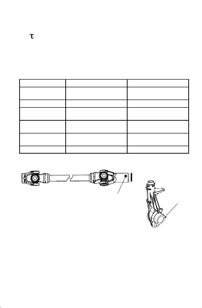
(1) Front Prop Shaft
Yoke
Premium U-Joint Grease Locate fittings and grease.
(2) Ball Joint Premium All Season Grease Locate fittings and grease.
(1)
(2)

68
MAINTENANCE AND LUBRICATION
Engine Oil
Polaris Premium 4 Synthetic Oil is the only oil recommended for use
in this engine. Use of another API certified “SH” oil is acceptable as
long as it’s 0W-40. Oil may need to be changed more frequently if
Polaris Premium 4 is not used. S ee page 111 for the part numbers of
Polaris products.
Always check and change the engine oil at the intervals outlined in the
Periodic Maintenance Chart beginning on page 63.
CAUTION
Using a non-recommended oil may cause serious engine damage.
Use only Polaris Premium 4 All Season Synthetic Oil or an API
certified 0W-40 “SH” oil. Never substitute or mix oil brands.
69
MAINTENANCE AND LUBRICATION
Oil Ch eck
1. Position the vehicle on a
level surface.
2. Place the transmission in
PARK.
3. Start the engine. Allow it to
idle for 30 seconds.
4. Turn the engine off.
5. Remove the dipstick.
Wipe it clean.
6. Reinstall the dipstick completely.
7. Remove the dipstick. Check the oil
level.
8. Add oil as needed to bring the
level between the minimum and
maximum marks (A). Do not
overfill.
H
N
P
L
R
A
70
MAINTENANCE AND LUBRICATION
Oil and Filter Change
Always change the engine oil at the intervals outlined in the Periodic
Maintenance Chart beginning on page 63. Always change the oil filter
when changing oil. Change the oil more often if the vehicle is routinely
subjected to:
S operation in dusty or wet conditions.
S operation when air temperature is below -12° C.
S short trips at -12° to -1° C. (engine fails to reach operating tempera-
ture).
CAUTION
If the Quadricycle is left without oil in the system for extended
periods, the oil pump may lose its prime, which could result in
engine damage. Always replace the oil and filter within a few
hours of draining the oil. Do not allow the vehicle to be without oil
overnight.
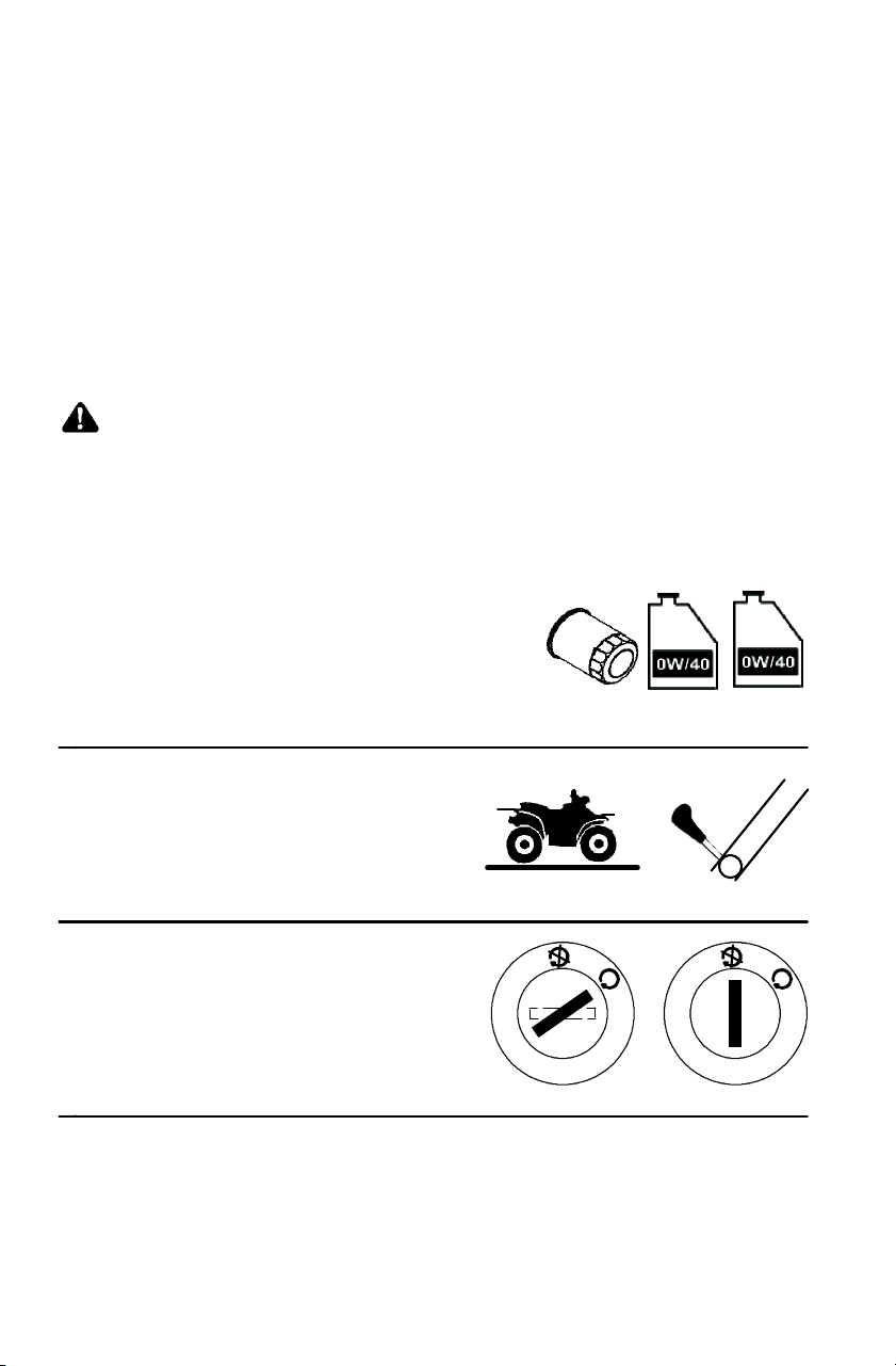
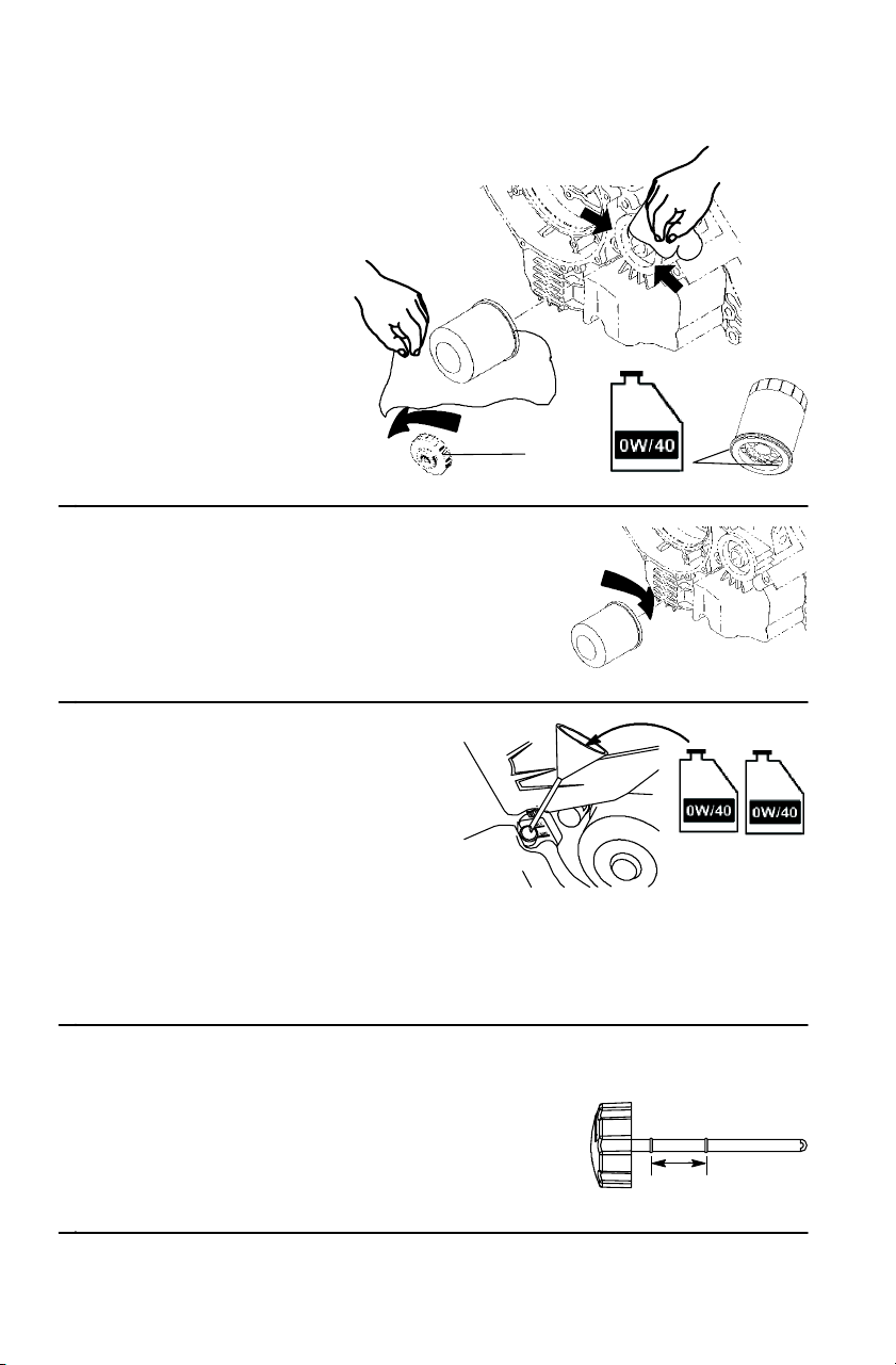
1. Use Polaris-recommended
products.
S Oil filter (P/N 3084963)
S Two .95 liter bottles of 0W/40 oil
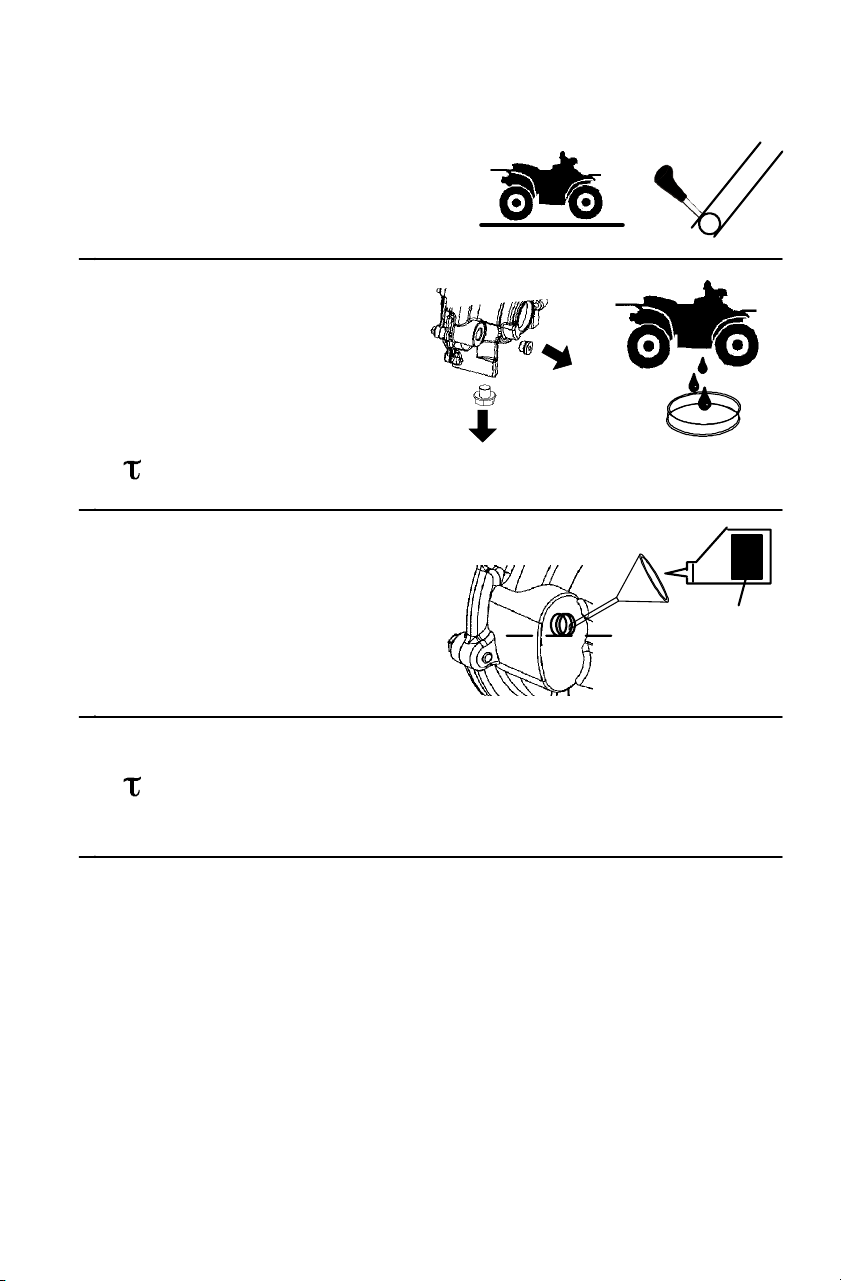
1. Position the vehicle on a
level surface.
2. Place the transmission in
PARK.
3. Start the engine. Allow it
to idle for two minutes.
4. Turn the engine off.
H
N
P
L
R

71
MAINTENANCE AND LUBRICATION
Oil and Filter Change
5. Place a drain pan under the
vehicle.
6. Remove the drain plug.
7. Drain the oil.
CAUTION
Hot oil may result in serious
burns. Do not allow hot oil to
contact skin.
8. Clean the drain plug. Reinstall the drain
plug with a new sealing washer.
=19-23 N-m
9. Disconnect the lower oil delivery
hose.
10. Remove the screen fitting from
the oil tank. Clean the fitting.
11. Seal the fitting threads with
LOCTITE PST 505 or PTFE seal
tape.
12. Reinstall the screen fitting. Rotate the
fitting clockwise a minimum of 2 1/2
turns into the tank threads. Continue to
rotate the fitting until the nipple of the
fitting aligns with the mark on the tank.
NOTE: Do not over-tighten. Maximum torque
for the screen fitting is 34 N-m.
13. Reinstall the oil line.
A
72
MAINTENANCE AND LUBRICATION
Oil and Filter Change
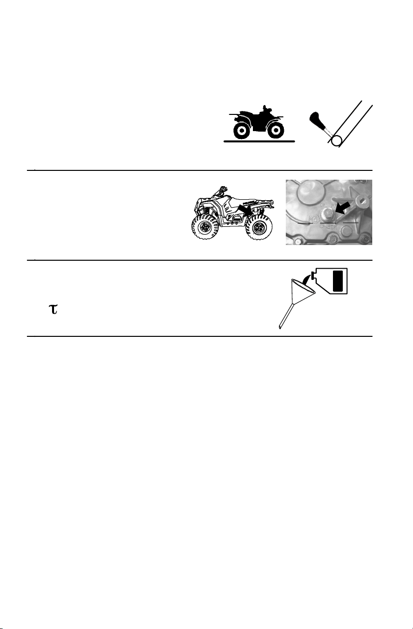
14. Place towels under
the oil filter.
15. Using an oil filter
wrench (A), turn the
filter
counterclockwise to
remove it.
16. Clean the filter
sealingareaonthe
engine.
17. Install the new oil filter.
After the filter contacts the
engine surface, turn it 1/2
turn by hand.
18. A small amount of engine oil
will remain in the crankcase.
Remove the drain plug on the
lower right side of the
crankcase to drain the oil.
Reinstall the drain plug.
19. Remove the dipstick. Add 1.9
liters of 0W/40 oil. If the sump is not
drained, add about 1. 5 liters initially.
20. Reinstall the dipstick.
21. Prime the oil pump using the procedure on page 73. Then stop
the engine and inspect for leaks.
22. Check the oil level. Add oil as needed
to bring the level between the
minimum and maximum marks (A).
Do not overfill.
A

73
MAINTENANCE AND LUBRICATION
Oil and Filter Change
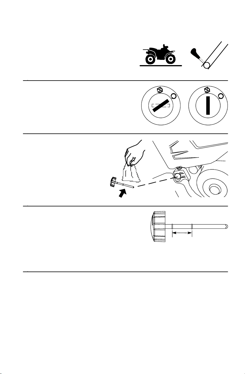
Oil Pump Priming
Prime the oil pump when
the oil hose connection
between the oil tank and
pump inlet has been
disconnected.
1. Clamp or pinch off the
vent line approximately
5 cm from the oil tank,
between the end of the oil
tank vent fitting (A) and t he
vent line’s pressure relief slit (B).
2. Start the engine. Allow it
to idle for 10-20 seconds.
3. Turn the engine off.
4. Remove the clamp. If the line is bled properly, you should hear a
rush of air, indicating that the line i s properly primed and ready for
operation. If you do not hear air, the line was not bled properly.
Repeat the priming procedure.
5cm
A
B
74
MAINTENANCE AND LUBRICATION
Transmission Oil Check
See page 67 for recommended lubricants. See page 111 for the part
numbers of Polaris products.
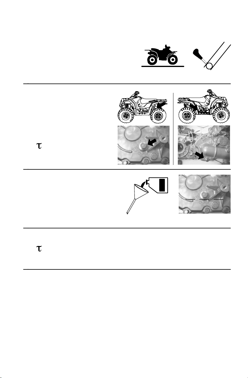
1. Position the vehicle on a
level surface.
2. Place the transmission in
PARK.
3. Remove the fill plug.
Check the oil level.
4. Maintain the level at the
bottom of the fill hole
threads.
5. Add fluid as needed.
6. Reinstall the fill plug.
=30 N-m
H
N
P
L
R
75
MAINTENANCE AND LUBRICATION
Transmission Oil Change
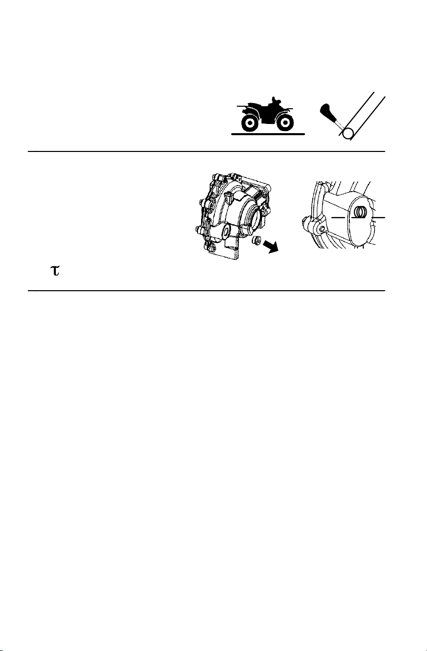
1. Position the vehicle on a
level surface.
2. Place the transmission in
PARK.
3. Remove the fill plug.
4. Remove the drain plug.
5. Drain the fluid into a
drain pan.
6. Clean the drain plug.
Reinstall the drain plug.
=30 N-m
7. Add 948 ml of the
recommended fluid. See
page 67.
8. Maintain the level at the
bottom of the fill hole
threads.
9. Reinstall the fill plug.
=30 N-m
10. Check for leaks.
H
N
P
L
R
76
MAINTENANCE AND LUBRICATION
Front Gearcase Oil Check
See page 67 for recommended lubricants.
1. Position the vehicle on a
level surface.
2. Place the transmission in PARK.
3. Remove the fill plug.
4. Maintain the level at
the bottom of the fill
hole threads.
5. Add the recommended
oil as needed.
6. Reinstall the fill plug.
=11-14 N-m
H
N
P
L
R
150 ml
77
MAINTENANCE AND LUBRICATION
Front Gearcase Oil Change
1. Position the vehicle on a
level surface.
2. Place the transmission in PARK.
3. Remove the fill plug.
4. Remove the drain plug.
5. Drain the fluid into a
drain pan.
6. Clean the drain plug.
Reinstall the drain plug.
=15 N-m
7. Add 150 ml of the
recommended fluid. See
page 67.
8. Maintain the level at the
bottom of the fill hole
threads.
9. Reinstall the fill plug.
=11-14 N-m
10. Check for leaks.
H
N
P
L
R
78
MAINTENANCE AND LUBRICATION
Engine Cooling System
Any time the cooling system has been drained for maintenance or
repair, replace the coolant with a fresh mixture of antifreeze and water.
Drain the cooling system every two years. Add fresh coolant.
Polaris recommends the use of Polaris Premium 60/40
anti-freeze/coolant or a 50/50 mixture of high quality aluminum
compatible anti-freeze/coolant and distilled water. P olaris Premium
60/40 is premixed and ready t o use. Do not dilute with water. See page
111 for the part numbers of Polaris products.
NOTE: Always follow the manufacturer’s mixing recommendations
for the freeze protection required in your area.
Bottle Coo lan t Level
Some coolant level drop on new machines is
normal, as the system is purging itself of
trapped air. Add coolant as needed.
NOTE: Check the coolant level in the
radiator any time the recovery
bottle has run dry. Add coolant as
needed.
1. Check the coolant level
when the fluid is cool.
2. Remove the left side panel.
Seepage87.
NOTE: Maintain coolant level
between the minimum
and maximum marks on the
bottle (when the fluid is cool).
3. View the coolant level.
4. Add coolant as needed.
5. Reinstall the side panel.

79
MAINTENANCE AND LUBRICATION
Engine Cooling System
Radiator Coolant Level
WARNING
Escaping steam can cause severe
burns. Never remove the pressure
cap while the engine is warm or hot.
1. Open the front box cover.
2. Open the access door.
3. Remove the radiator pressure
cap.
4. View the coolant level.
5. If coolant is not visible, slowly
add coolant through the radiator
filler neck.
6. Reinstall the pressure cap.
7. Secure the access door and box cover.
NOTE: Use of a non-standard pressure cap will not allow the
recovery system to function properly. Contact your dealer for
the correct replacement part.

80
MAINTENANCE AND LUBRICATION
Brakes
Brake Fluid
Check brake fluid levels for both brake systems before each use of the
vehicle. Always keep brake fluid at an adequate level. Do not overfill.
The brakes should feel firm when they’re applied. Spongy or weak
brakes may indicate a fluid leak or low fluid level. A low fluid l evel
may also mean that brake pads are worn and need to be replaced. Do
not operate the vehicle with spongy or weak brakes. See your dealer for
service.
WARNING
Operating the Quadricycle with a spongy brake can result in loss
of braking, which could cause an accident.
Never operate the Quadricycle with spongy-feeling brakes.
If the fluid level is low add DOT 3 brake fluid only. See page 111 for
the part numbers of Polaris products.
WARNING
An over-full master cylinder may cause brake drag or brake
lock-up, which could result in serious injury or death. Maintain
brake fluid at the recommended level. Do not overfill.
Under normal operation, the diaphragm extends into the reservoir as
fluid level drops. If the fluid level is low and the diaphragm is not
extended, a leak is likely and the diaphragm should be replaced.
Always fill the reservoir as needed whenever the cover is loosened or
removed to ensure proper diaphragm operation.
WARNING
Never store or use a partial bottle of brake fluid. Brake fluid is
hygroscopic, meaning it rapidly absorbs moisture from the air.
The moisture causes the boiling temperature of the brake fluid to
drop, which can lead to early brake fade and the possibility of
accident or severe injury. After opening a bottle of brake fluid,
always discard any unused portion.
A
B
81
MAINTENANCE AND LUBRICATION
Brakes
Brake Fluid
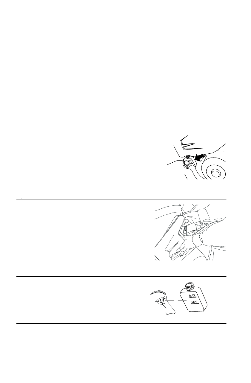
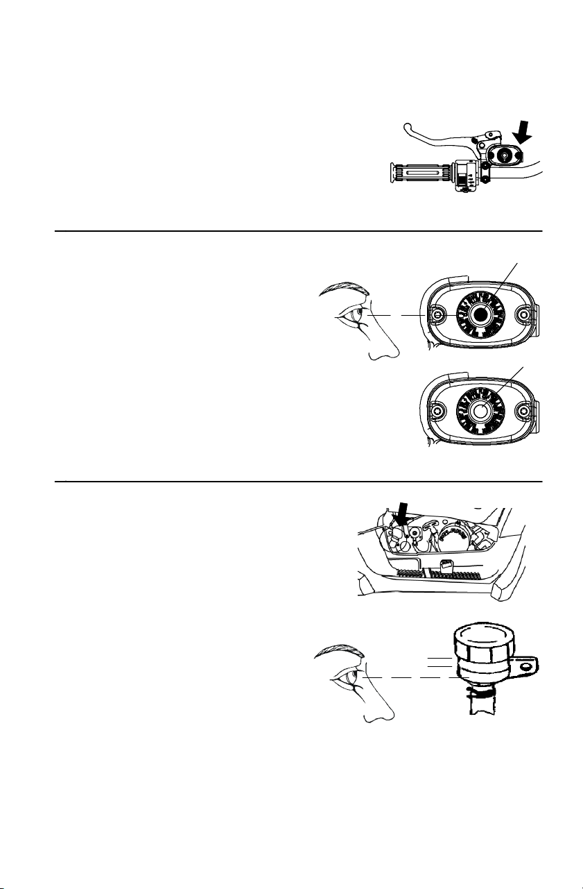
Master Cylinder (Handlebar)
The master cylinder is located on
the left handlebar. Maintain the
fluid level 6 m m below the top edge
of the master cylinder. Do not overfill.
1. Position the vehicle on a
level surface. Make sure the
handlebars are straight.
2. View the fluid level through
the indicator window (eye)
on the top of the master
cylinder.
Full (A): Dark eye
Low (B): Clear eye
Add the recommended fluid as needed.
Do not overfill.
Master Cylinder (Foot Brake)
The reservoir is located near
the foot brake. Maintain the
fluid level between the
minimum and maximum
marks. Do not overfill.
MIN
MAX

1mm
82
MAINTENANCE AND LUBRICATION
Brakes
Brake Check
The front and rear brakes are hydraulic disc brakes, activated by
applying the foot brake. The handlebar brake is also hydraulic. Both
brake systems are self-adjusting.
Perform the following checks to keep the brake systems in good
operating condition. Check more often if brakes are used heavily
during normal operation.
1. Check the brake systems
regularly for fluid leaks.
2. Check the brakes for excessive
travel or spongy feel.
3. Check the brake pads for wear,
damage or looseness. Replace
pads when they are worn to 1 mm.
4. Check the security and surface
condition of the brake discs.
83
MAINTENANCE AND LUBRICATION
Steering / Suspension
Toe Alignment
WARNING
Do not attempt to adjust alignment. All steering adjustments
should be performed by an authorized Polaris dealer.
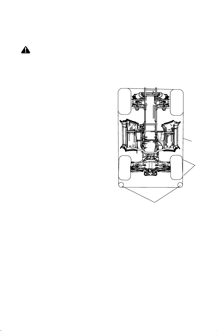
Use the following procedure to check the toe alignment of the vehicle.
The recommended toe alignment is 3-6 mm toe out.
1. Set the handlebars in a
straight-ahead position.
NOTE: Thesteeringfrogcan
be used as an indicator
of whether the
handlebars are straight.
The frog should always
point straight back
from the steering post.
2. Place stands (A) in front of
the vehicle, perpendicular to
the rear tires.
3. Tie an elastic string
around the s tands, making
sure the string just touches
the side surface of the rear
tires on each side of the
vehicle and goes around
the stands in front of the
vehicle (B).
4. Measure t he distance from the string to the rim at the front and rear
of the front rim (C). The rear measurement should be 2 to 3 mm
more than the front measurement.
NOTE: If you discover improper alignment, see your Polaris dealer
for service.
A
B
C

84
MAINTENANCE AND LUBRICATION
Steering / Suspension
Steering Assembly
Check the steering assembly of the vehicle periodically for loose nuts
and bolts. If loose nuts and bolts are found, see your Polaris dealer for
service before operating the vehicle.
Handlebar Adju stment
1. Remove the upper
headlight pod.
2. Loosen the four bolts.
3. Adjust the handlebars to the
desired height. Be sure the
handlebars do not contact the gas
tank or any other part of the
machine when turned fully to the
left or right.
4. Torque the front two bolts first.
5. Torque the rear two bolts last.
=14-17 N-m
NOTE: A gap of up to 3 mm should remain at the rear bolts.
WARNING
Improper adjustment of the handlebars or incorrect torquing of
the adjuster block tightening bolts can cause limited steering or
loosening of the handlebars, resulting in loss of control. Follow
the adjustment procedures exactly, or see your Polaris dealer for
service.
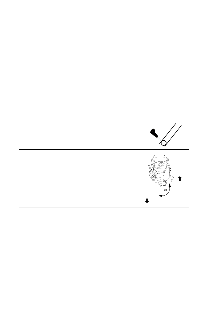
RPM
RPM
85
MAINTENANCE AND LUBRICATION
Carburetor Idle Adjustment (if equipped)
IMPORTANT: Your carbureted Polaris vehicle is calibrated at the
factory for optimal performance at altitudes ranging from zero to 1800
meters and at temperatures of 4 degrees C. or higher. Above 1800
meters the engine air/fuel mixture becomes too rich and the engine
loses approximately 3% of its power for each 300 meter increase in
elevation. Although this power cannot be regained, adjustments to the
carburetor and drive system can be made to allow more efficient
operation. Optional jets and clutch components, available from your
Polaris dealer, are required for operation above 1800 meters. Jetting is
required only when operating below 4 degrees C. at 1800 meters and
lower.
NOTE: Operating the engine with improper jetting can cause poor
performance, overheating or engine damage. See your
Polaris dealer for more information about jetting.
If necessary, the carburetor can be adjusted.
1. Place the transmission in PARK.
2. Operate the engine for about five
minutes.
3. Place the transmission in gear.
Lock the parking brake.
4. Adjust the carburetor idle screw clockwise
to raise RPM or counterclockwise to l ower
RPM.
H
N
P
L
R
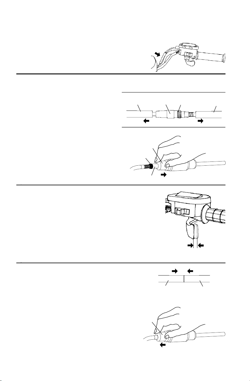
A
B
C
B
B
A
C
1.6-3.2 mm
B
B
B
86
MAINTENANCE AND LUBRICATION
Throttle Cable Freeplay Adjustment
1. Locate t he throttle cable
adjuster on the
handlebar.
2. Expose the cable adjuster (A) as outlined below.
Sportsman 500
Slide the two boots (B) off the
cable adjuster.
Sportsman 500 EFI
Squeeze the end of the rubber
boot (B) and slide it far enough to
expose t he end of the cable
adjuster.
3. Loosen the locknut (C).
4. Turn the adjuster until 1. 6-3.2 mm
of freeplay exists at the lever.
On the EFI model, rotate the
boot to turn the adjuster.
NOTE: Move the throttle lever
back and forth while
adjusting.
5. Tighten the locknut.
6. Reinstall the boot(s) to
their original position.
NOTE: Engine RPM should
not increase when
steering is turned full
left or right. Readjust
cable freeplay if this
occurs.
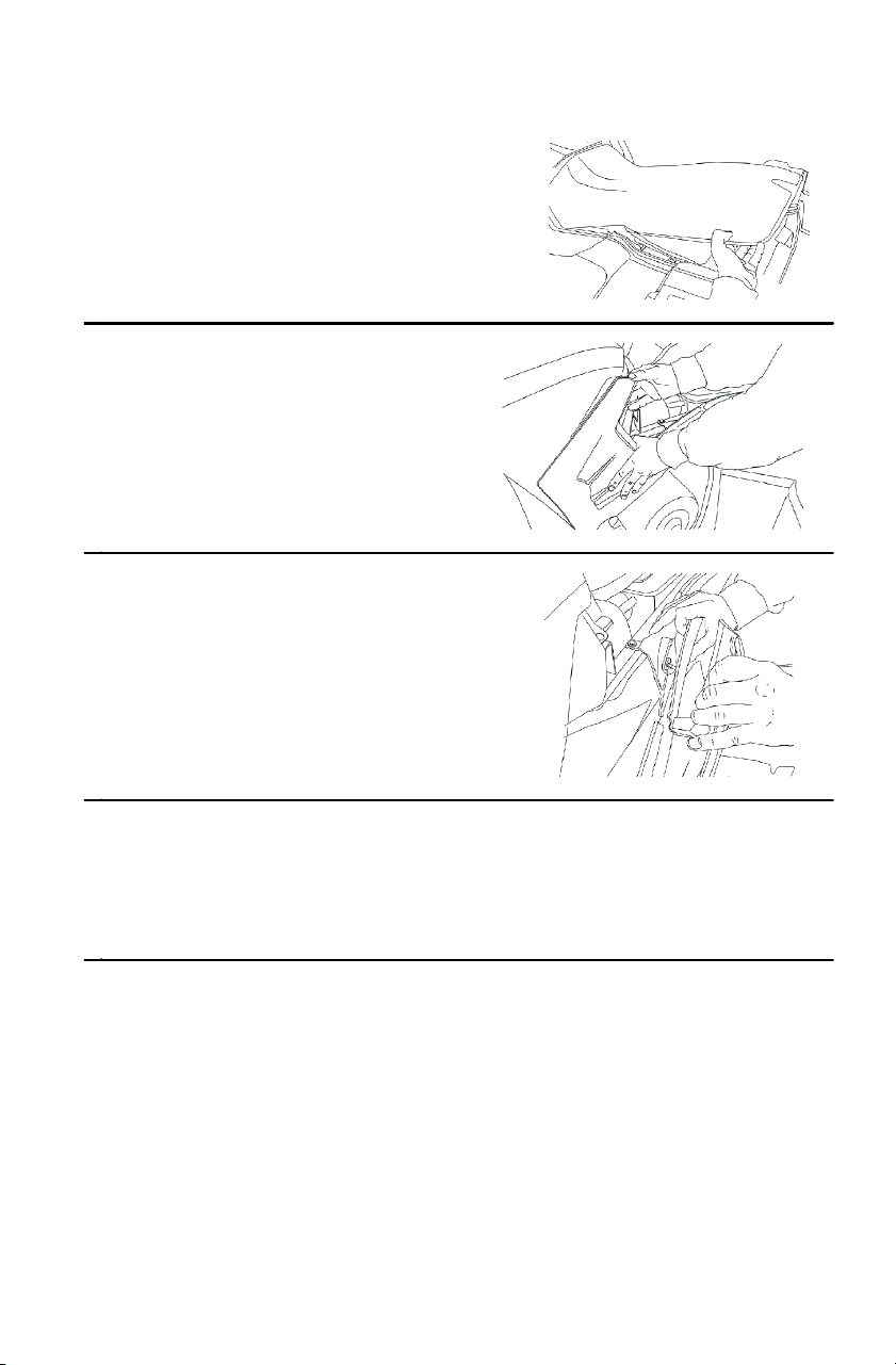
87
MAINTENANCE AND LUBRICATION
Side Panel Removal
1. Remove the seat.
2. Grasp the rear of the side panel
near the rear cab.
3. With a firm motion, pull the
panel outward to disengage the
side panel from t he grommet.
4. Pull the panel downward and rearward to remove it from the
Quadricycle.
5. Reinstall the side panel by reversing the removal procedure.
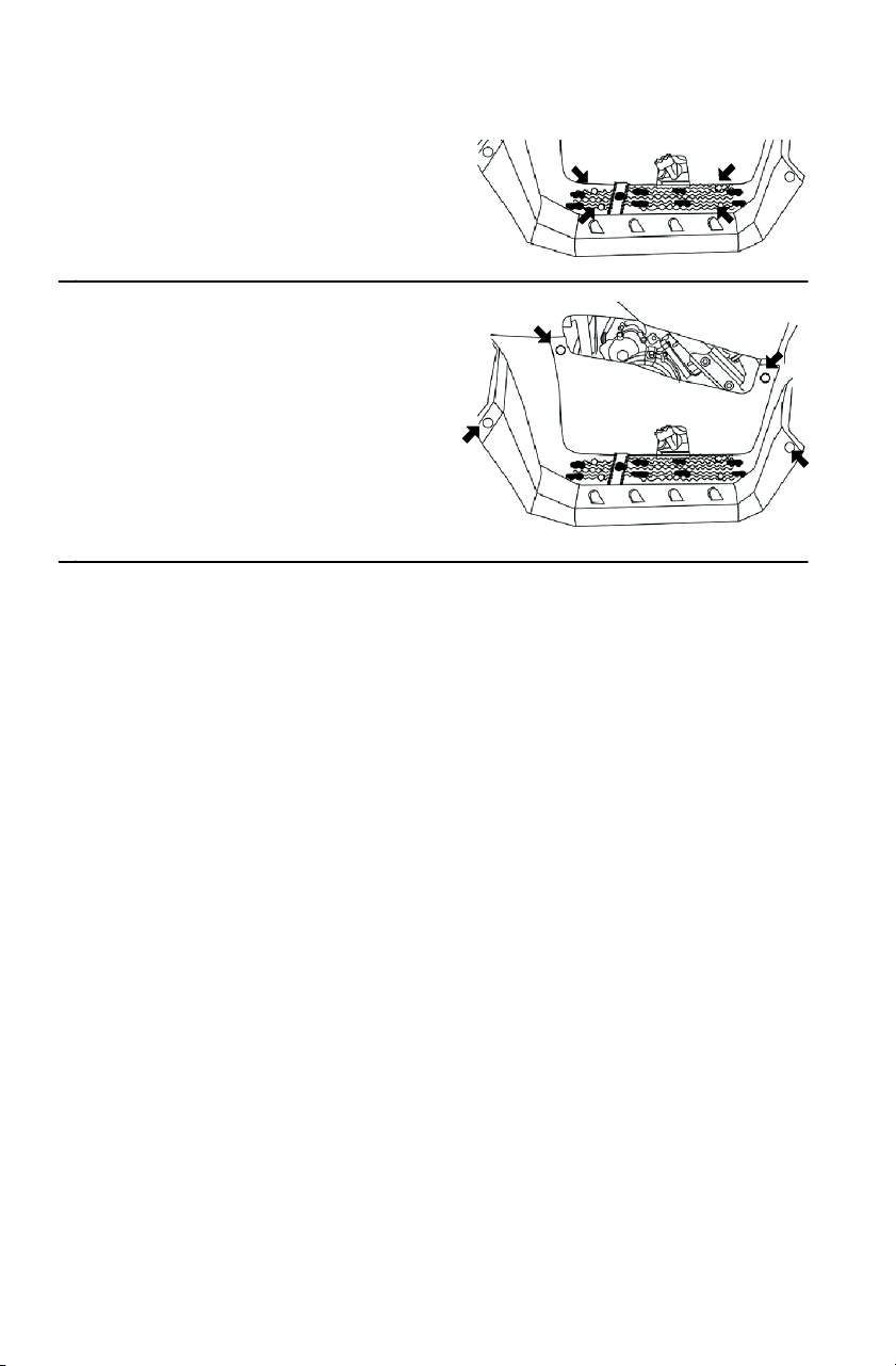
88
MAINTENANCE AND LUBRICATION
Footwell Removal
1. Remove the four screws on
the bottom of the footwell.
2. Use a flat screwdriver or
sidecutters to remove the
plastic rivets securing the
footwell to the fenders.
3. Remove the footwell.
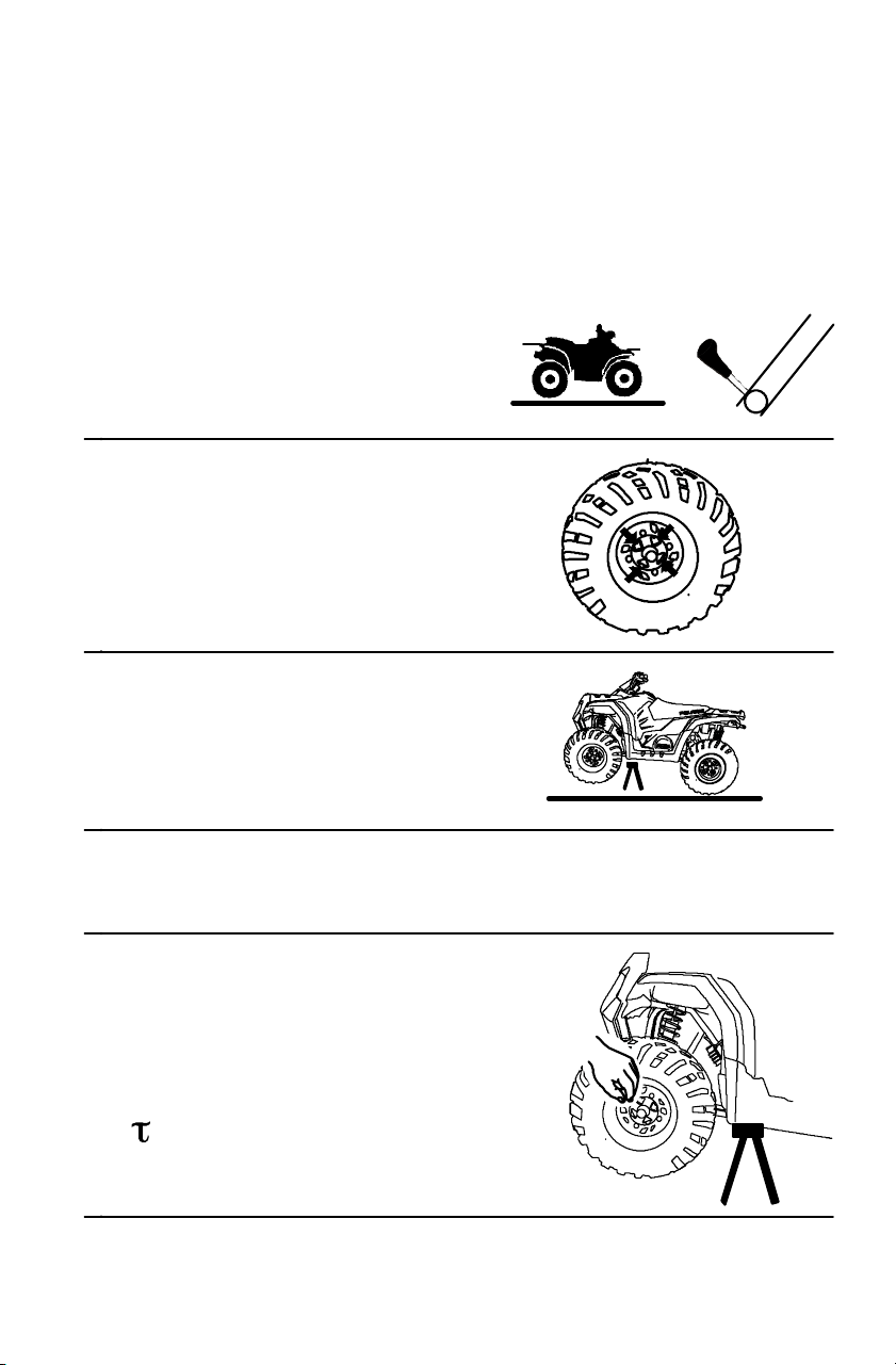
89
MAINTENANCE AND LUBRICATION
Wheel Removal / Installation
CAUTION
Operating with improperly installed wheels will affect vehicle
handling and could cause an accident resulting in serious injury or
death. Always use original equipment size and type when
replacing tires. Install wheels properly.
1. Position the vehicle on a
level surface.
2. Place the transmission in PARK.
3. Loosen the wheel nuts
slightly.
4. Safely place jackstands
under the vehicle.
5. Remove the wheel nuts.
6. Remove the wheel.
7. Place the wheel on the hub.
8. Install the wheel nuts
finger tight.
9. Carefully remove the jackstands.
10. Torque the wheel nuts.
=27 N-m
H
N
P
L
R
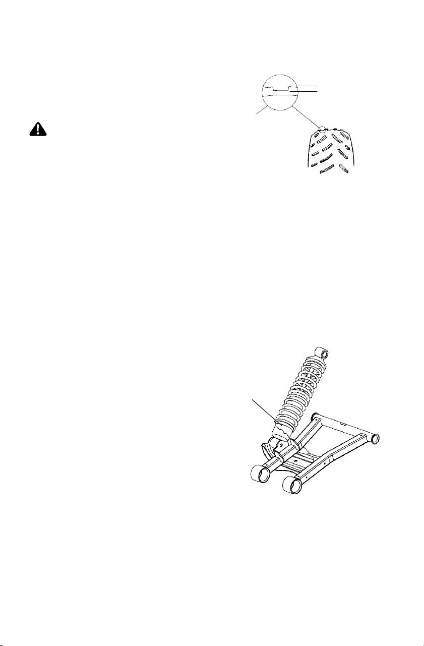
3mm
90
MAINTENANCE AND LUBRICATION
Tires
Tire Tread Depth
Always replace tires when tread
depthiswornto3mmorless.
WARNING
Operating your vehicle with worn tires,
improperly inflated tires, non-standard
tires or improperly installed tires will
affect vehicle handling and could cause
an accident.
Maintain proper tire pressure as described on the decal on your
vehicle and in the specifications section of the owner’s manual
beginning on page 112.
Use only original equipment size and type when replacing tires.
Make sure the wheels are installed properly.
Replace tires when the tread depth measures 3 mm or less.
Wheel and Hub Tightenin g
Wheel hub and bearing tightness and spindle nut retention are critical
items. These services must be performed by an authorized dealer.
Rear Spring
The rear shock absorber spring is
adjusted by rotating the adjuster (A)
either clockwise or
counterclockwise to increase or
decrease spring tension.
NOTE: Accessory springs are
available through your
Polaris dealer.
A
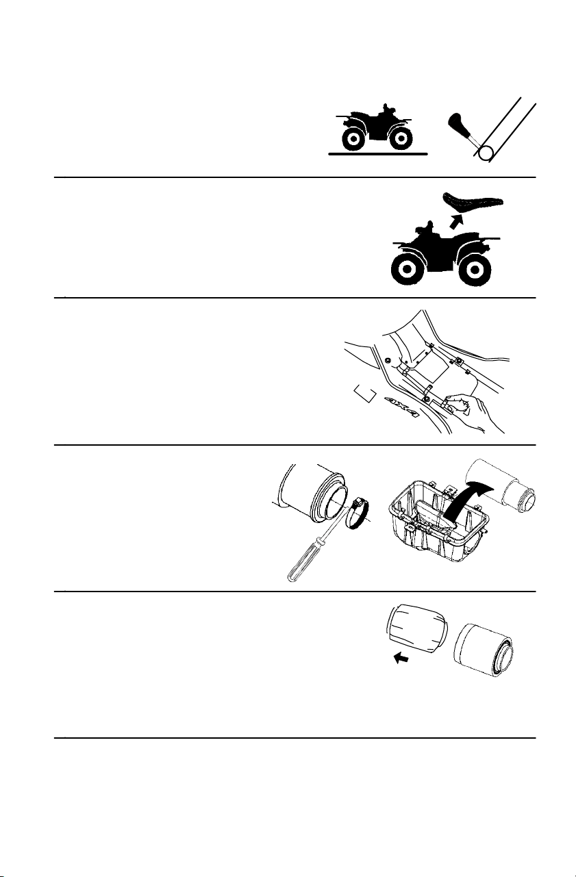
91
MAINTENANCE AND LUBRICATION
Air Filter
1. Position the vehicle on a
level surface.
2. Place the transmission in PARK.
3. Remove the seat.
4. Unlatch the air box clips.
Remove the air box cover.
5. Loosen the hose
clamp.
6. Remove the filter.
7. Remove the pre-filter from the
filter. Wash the pre-filter in soapy
water. Rinse and air dry.
NOTE: Replace the filter if needed.
8. Reverse the steps to reinstall all components.
H
N
P
L
R
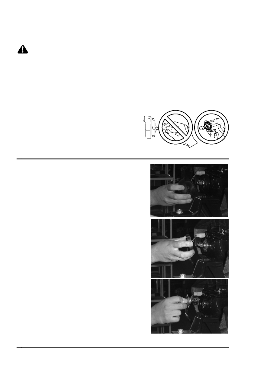
92
MAINTENANCE AND LUBRICATION
Lights
WARNING
Poor lighting can result in loss of control or an accident. Lights
become dirty during normal operation. Wash the headlights and
tail lights frequently.
Hot components can cause serious burns to skin. Do not service
the headlamps until they’ve cooled.
Headlight Lamp Replacement
When servicing a halogen lamp,
do not touch the lamp with bare
fingers. Hold the plastic part of
the lamp. Oil from your skin
leaves a residue, causing a hot
spot that will shorten the life of the lamp.
1. Place the transmission in
PARK.
2. Open the front rack cover.
3. Remove the access panel at the
back of the headlight.
4. Pull the harness plug to
disconnect it from the back of
the headlight.
5. Remove the rubber cover from
the back of the headlight.
6. Turn the collar
counter-clockwise and
carefully remove the collar and
socket.
7. Remove the lamp. Apply
dielectric grease to the socket
and install a new lamp.
8. Reverse all steps to reassemble
the headlight.
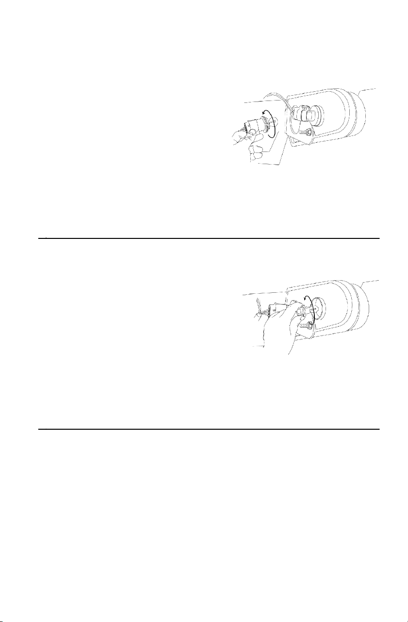
93
MAINTENANCE AND LUBRICATION
Lights
Taillig h t Lamp Replacement
1. Place the transmission in
PARK.
2. Rotate the taillight socket
counterclockwise to remove
it.
3. Remove the lamp.
4. Apply dielectric grease to
the socket.
5. Install the new lamp.
6. Test the lamp for proper operation.
7. Reinstall all components in reverse order.
Rear Tu rn Signal Lamp Replacement
1. Place the transmission in
PARK.
2. Rotate the turn signal socket
counterclockwise to remove
it.
3. Remove the lamp.
4. Apply dielectric grease to the
socket.
5. Install the new lamp.
6. Test the lamp for proper operation.
7. Reinstall all components in reverse order.
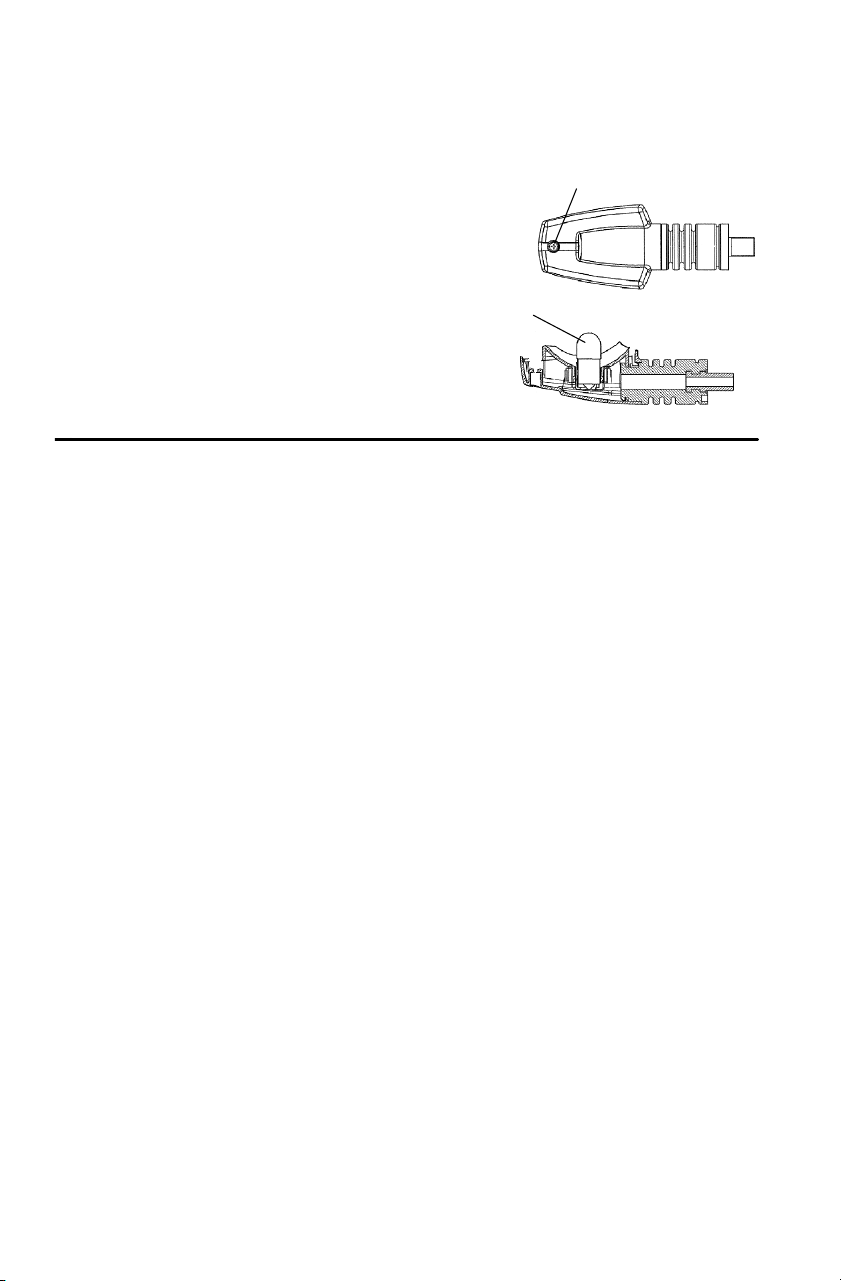
94
MAINTENANCE AND LUBRICATION
Lights
Front Turn Signal Lamp Replacement
1. Place the transmission in PARK.
2. Remove the lens attachment
screw (A).
3. Rotate the lamp (B) to remove it.
4. Install the new lamp.
5. Reinstall the lens.
A
B
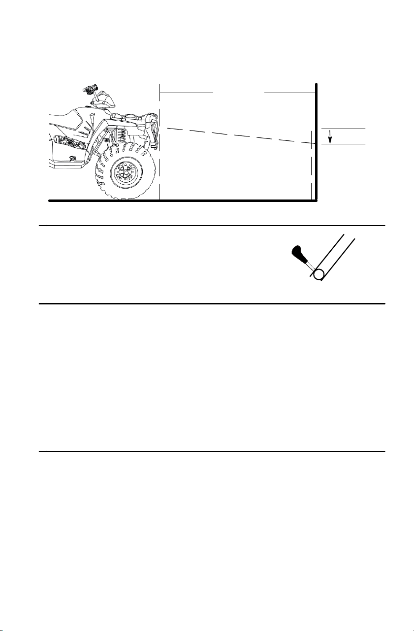
95
MAINTENANCE AND LUBRICATION
Lights
Headlight Beam Adjustment
1. Position the vehicle on a level surface.
The headlight should be approximately
7.6 meters from a wall.
2. Place the transmission in PARK.
3. Measure the distance from the floor to the center of the headlight
and make a mark on the wall at the same height.
NOTE: Include rider weight on the seat when measuring.
4. Start the engine. Turn t he headlight switch to high beam.
5. Observe the headlight aim on the wall. The most intense part of
the headlight beam should be aimed 5.1 cm below the mark placed
on the wall.
6. Tighten or loosen the lower headlight screws to adjust the beam
upward or downward or to the left or right.
7.6 m
x
5.1 cm
x
H
N
P
L
R

96
MAINTENANCE AND LUBRICATION
Spark Plugs
Spark Plug Condition
Normal
The insulator tip is tan or brown. There are few combustion deposits.
The electrodes are not burned or eroded. This indicates the proper t ype
and heat range for the engine and the service.
NOTE: The tip should not be white. A white insulator tip indicates
overheating, caused by use of an improper spark plug or
incorrect carburetion or throttle body adjustments.
Fouled
The insulator tip is black. A damp film covers the firing end. There
may be a carbon layer over the entire nose. Generally, the electrodes
are not worn. General causes of fouling are excessive oil consumption,
improper use of the choke, or incorrect carburetion or throttle body
adjustments.
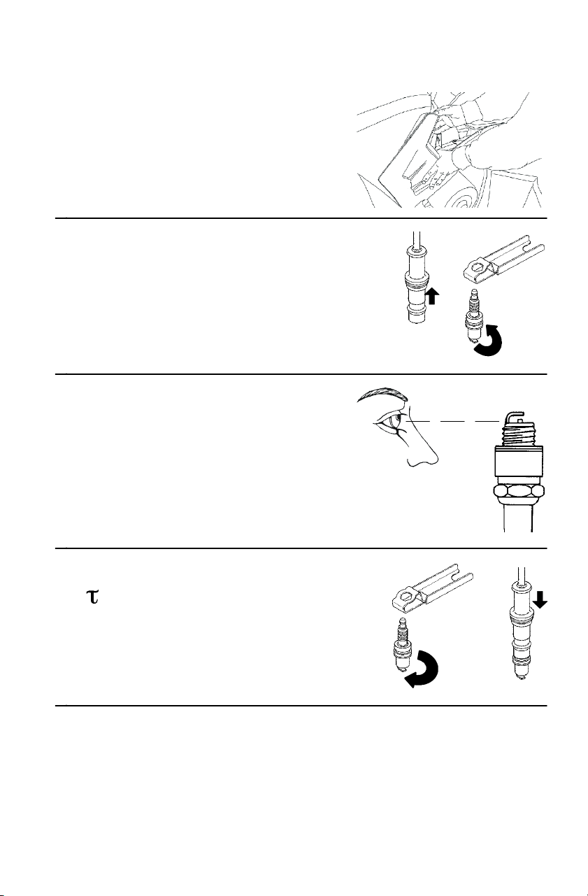
97
MAINTENANCE AND LUBRICATION
Spark Plugs
1. Remove the left side panel.
Seepage87.
2. Remove the spark plug cap.
3. Use the spark plug
wrench to remove the
spark plug. Turn the plug
counterclockwise to
remove it.
4. Inspect the electrodes for
wear and carbon buildup.
Replace worn or fouled
plugs. Verify that the gap
is at specification before
installation.
5. Reinstall the spark plug.
=24 N-m
6. Reinstall the spark plug
cap.
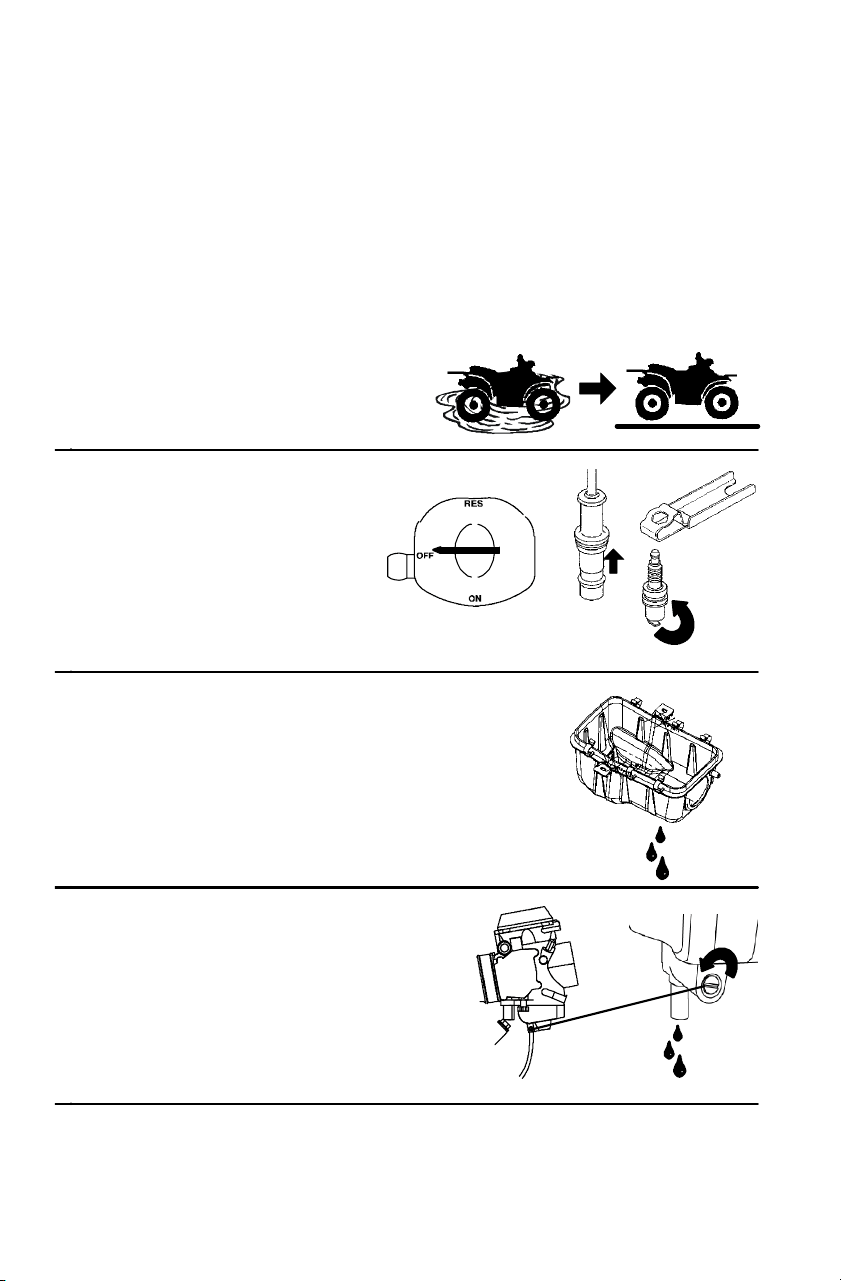
98
MAINTENANCE AND LUBRICATION
Vehicle Immersion
CAUTION
If the vehicle stops while fully submerged, major engine damage
can result if the machine is not thoroughly inspected. Take the
vehicle to your dealer before starting the engine.
If your vehicle has been totally submerged in water and it’s impossible
to have it serviced before further operation, perform the following
procedure.
1. Move the vehicle out of
the water.
2. Turn the fuel valve
off (if equipped).
3. Remove the spark plug.
Seepage96.
4. Drain any water found in
the air box.
5. Carbureted models only:
Loosen the carburetor drain
screw and drain the
carburetor.
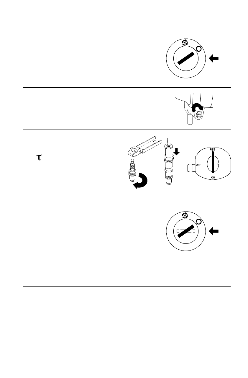
99
MAINTENANCE AND LUBRICATION
Vehicle Immersion
6. Turn the ignition key past the ON
position to engage the starter.
Engage the s tarter for only 2-3
seconds.
7. Carbureted models only: Tighten
the carburetor drain screw.
8. Dry the spark plug.
Reinstall the spark plug.
=24 N-m
9. Turn the fuel valve to
“RES” (if equipped).
10. Attempt to start the engine. If
necessary, repeat the drying
procedure.
11. Have the vehicle serviced by your
dealer promptly, whether you
succeed in starting it or not.
NOTE: If water has been ingested into the PVT, follow the procedure
for drying out the PVT. See page 61.
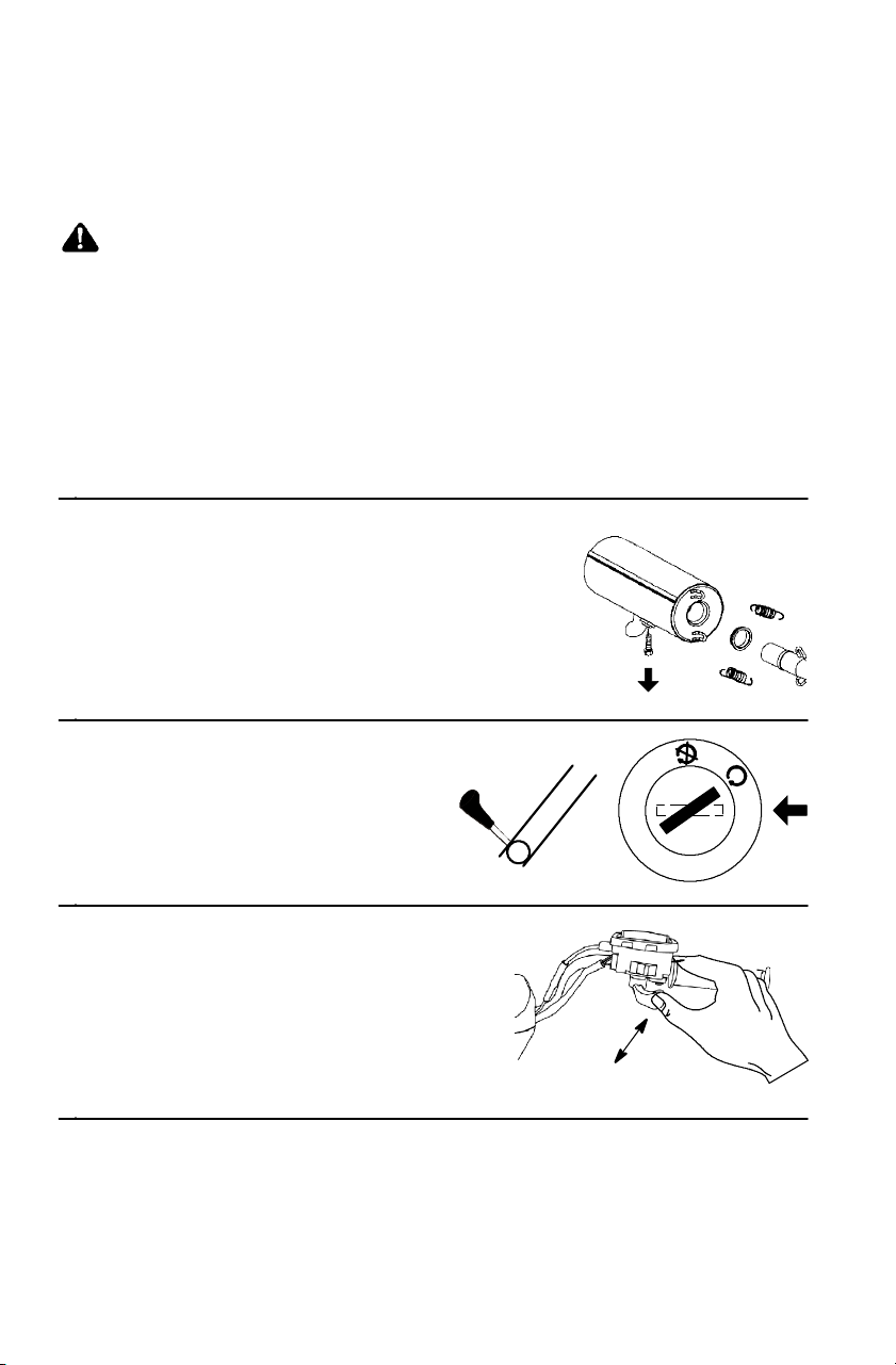
100
MAINTENANCE AND LUBRICATION
Spark Arrestor
Occasionally, the spark arrestor may accumulate carbon, which can
restrict the exhaust if left unattended. Purge the spark arrestor.
WARNING
Allow components to cool sufficiently before servicing. The
exhaust system can get extremely hot. Never run the engine in
an enclosed area or indoors. Exhaust contains poisonous carbon
monoxide gas. Never go under the vehicle while it’s inclined.
Remove any combustible materials from the area. Wear eye
protection and leather work gloves. Do not stand behind or in
front of the vehicle while purging.
1. Remove the arrestor
clean-out plug from the
bottom of the muffler.
2. Place the transmission in PARK.
3. Start the engine.
4. Quickly squeeze and
release the throttle lever
several times to purge
carbon from the system.
H
N
P
L
R

30 cm
101
MAINTENANCE AND LUBRICATION
Spark Arrestor
5. If carbon comes out of the
exhaust, cover or plug the
exhaust outlet. Wear
leather gloves for
protection.
6. Lightly tap on t he exhaust
pipe with a rubber mallet
while repeating step 4.
7. If particles are still
suspected to be in the
muffler , elevate the rear of
the vehicle 30 cm higher
than the front.
8. Place the transmission in
PARK.
9. Block the wheels.
10. Repeat steps 4 to 6 until
no more particles are
expelled.
11. Turn the engine off. Allow the arrestor to cool. Reinstall the
arrestor plug and remove the exhaust outlet cover or plug.
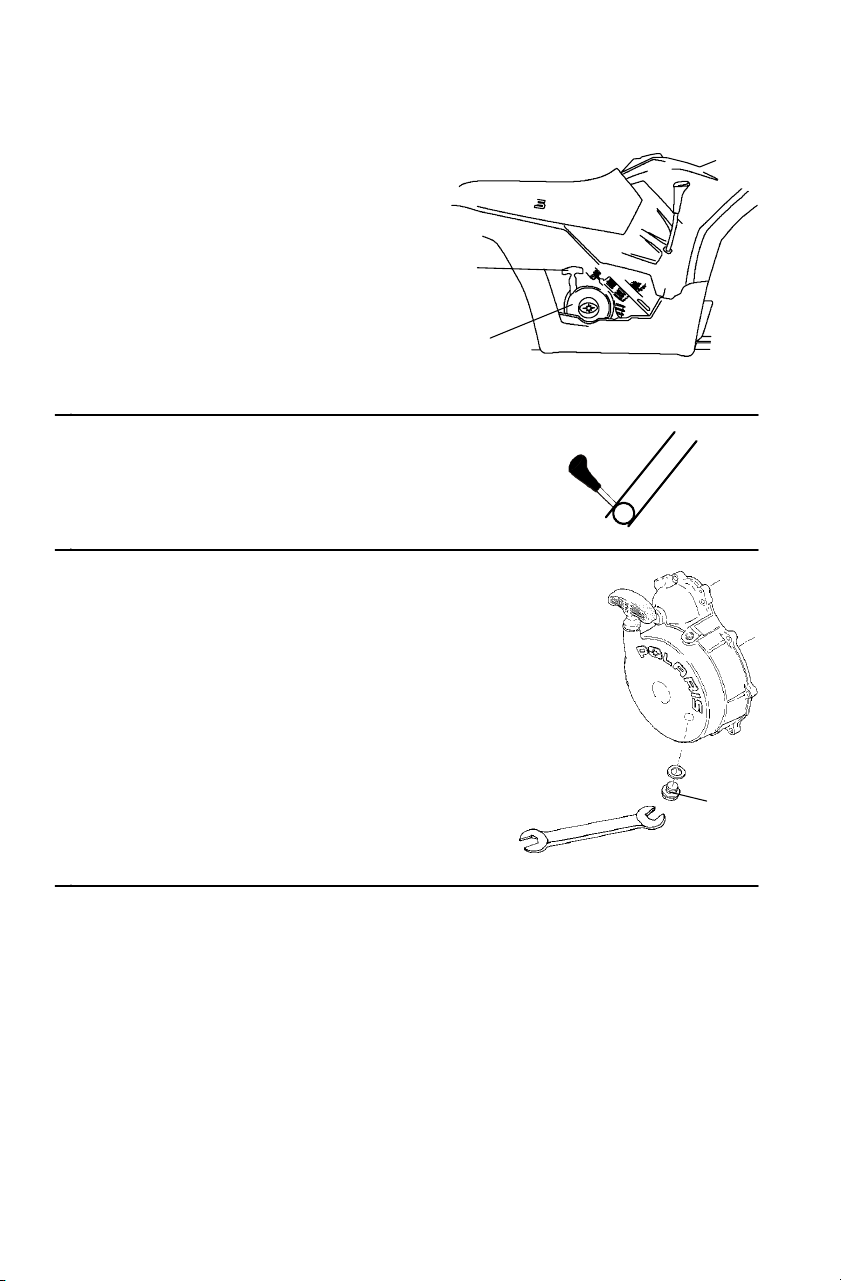
C
102
MAINTENANCE AND LUBRICATION
Recoil Housing Drain (if equipped)
Always drain the recoil
housing (A) after operating the
vehicle in wet conditions.
Always remove the drain plug
before storing the vehicle.
NOTE: W ater will enter the
recoil housing if the
starter handle (B) is
disengaged from the rope
guide when under water .
1. Place the transmission in PARK.
2. Using a wrench, remove the
drain screw (C) on the bottom of
the recoil housing.
3. Reinstall the screw after draining
the housing.
NOTE: Do not open the crankcase
drain unless the engine has
ingested water . On 4-cycle
engines, some engine oil
will be lost if the crankcase
drain is opened.
A
B
H
N
P
L
R

103
MAINTENANCE AND LUBRICATION
Battery
Always keep battery terminals and connections free of corrosion. If
cleaning is necessary, remove corrosion with a stiff wire brush. Wash
with a solution of one tablespoon baking soda and one cup water.
Rinse well with tap water and dry off with clean shop towels. Coat the
terminals with dielectric grease or petroleum jelly. Be careful not to
allow cleaning solution or tap water into a conventional battery.
WARNING
Battery electrolyte is poisonous. It contains sulfuric acid. Serious
burns can result from contact with skin, eyes or clothing.
Antidote:
External: Flush with water.
Internal: Drink large quantities of water or milk. Follow with milk
of magnesia, beaten egg, or vegetable oil. Call physician
immediately.
Eyes: Flush with water for 15 minutes and get prompt medical
attention.
Batteries produce explosive gases. Keep sparks, flame,
cigarettes, etc. away. Ventilate when charging or using in an
enclosed space. Always shield eyes when working near
batteries. KEEP OUT OF REACH OF CHILDREN.

104
MAINTENANCE AND LUBRICATION
Battery
WARNING
Improperly connecting or disconnecting battery cables can cause
sparks which could result in an explosion, causing serious injury or
death. When removing the battery , always disconnect the negative
(black) cable first. When reinstalling the battery, always connect the
negative (black) cable last.
Battery Removal
1. Place the transmission in PARK.
2. Disconnect the hold-down strap. Remove battery cover.
3. Remove the battery vent tube.
4. Disconnect the black (negative) battery cable first.
5. Disconnect the red (positive) battery cable next.
6. Lift the battery out of the Quadricycle. Be careful not to tip the
battery sideways, which could spill electrolyte.
NOTE: If electrolyte spills, immediately wash it off with a solution of
one tablespoon baking soda and one cup water to prevent
damage to the vehicle.
Battery Installatio n
1. Always install a fully charged battery.
2. Set the battery in the battery holder.
3. Install the battery vent tube.
4. Connect and tighten the red (positive) cable first.
5. Connect and tighten the black (negative) cable next.
6. Reinstall the battery cover and attach the hold-down strap.
7. Verify that cables are properly routed.
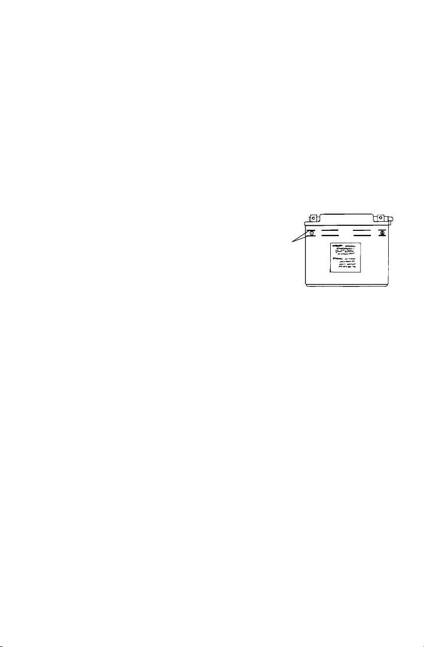
105
MAINTENANCE AND LUBRICATION
Battery
Battery Storage
Whenever the vehicle is not used for a period of three months or more,
remove the battery from the vehicle. Verify that it’s fully charged, and
store it out of the sun in a cool, dry place. Check battery voltage each
month during storage. Before reusing, take the battery to your dealer
for testing and recharging.
Power plug leads may need to be bent down so that the battery cover
can be installed.
Replenishing Battery Fluid
Check the battery fluid level often. The
fluid level should be kept between the
upper and lower level marks (A).
To refill use only distilled water. Tap
water contains minerals that are harmful
to a battery.
A

106
MAINTENANCE AND LUBRICATION
Cleaning the Vehicle
Keeping the vehicle clean will extend the life of components.
S Use a garden hose and a pail of mild soap and water
S Use a professional-type washing mitten, cleaning the upper body
first and the lower parts last.
S Rinse with clean water frequently.
S Wipe the vehicle dry with a chamois.
S Do not use high pressure water.
High pressure water may damage components. If a high pressure wash
system must be used, exercise extreme care to avoid directing water
onto the wheel bearings, transmission seals, body panels, brakes and
warning labels. Grease all fittings immediately after washing, and
allow the vehicle to run for a while to evaporate any water t hat may
have entered the engine or exhaust system.
NOTE: If warning and safety labels are damaged, contact your
Polaris dealer for free replacements.
Waxing the Vehicle
Unless it has a special finish, your Quadricycle can be waxed with any
non-abrasive automotive paste wax. Do not wax models that have a
camouflage finish.
CAUTION
Some products, including insect repellants and chemicals, will
damage plastic surfaces. Use caution when using these products
near plastic surfaces.

107
MAINTENANCE AND LUBRICATION
Storing the Vehicle
See page 111 for the part numbers of P olaris products.
Clean the Vehicle
See page 106.
Stabilize the Fuel
1. Fill the fuel tank.
2. Add Polaris Carbon Clean Fuel Treatment or Polaris Fuel
Stabilizer. Follow the instructions on the containe r . (Carbon Clean
Plus will reduc e the possibility of bacte rial growth in the fuel
system.) Allow 15-20 minutes of opera tion for the stabilizer to
disperse through the fuel system.
3. Turn the fuel valve off (if equipped).
4. Drain the car buretor bowl (if equipped).
Change Oil and Filter
Change the oil and filter. See page 70.
Air Filt er / Air Box
Inspect and clean (or replace) the pre-cleaner and air filter. Clean the air
box a nd drain the sediment tube. See page 91.
Breather Filter
Inspect and clean or replace the breather filter.
Check / Change Fluids
Inspect fluid levels and change fluids if necessary.
S Front Gearcase
S Transmission
S Brake F luid
Drain the Recoil Housing (if equipped)
See page 102.
Battery Storage
Remove the battery. Make sure that it’s fully charged.

108
MAINTENANCE AND LUBRICATION
Storing the Vehicle
Engine Fogging
1. Remove the spark plug and add 2-3 tablespoons of Premium 4
Synthetic 0W40 engine oil. To access the plug hole, use a section of
clear 1/4” hose and a small plastic squeeze bottle fille d with the
pre- mea sure d amount of oil.
2. Reinstall the spark plug. Torque to 24 Nm.
3. Apply diele ctric grea se to the inside of the spark plug ca p and install
the ca p onto the plug.
4. Turn the engine over severa l times. Oil will be forc ed in and around
the piston rings and ring lands, coa ting the cylinder with a protec tive
film of fresh oil.
CAUTION
Starting the engine during the storage period will disturb the
protective oil film, which can lead to engine damage. Never start
the engine during the storage period.
Battery Maintenance
Remove the battery and add distilled water to the proper level. Do not
use tap water, which may contain minerals that reduce battery life.
Apply dielectric grease to the terminal bolts and terminals. Charge the
battery at 1.4 amps or less until the specific gravity of each cell is
1.265 or greater. Store the battery in a cool, dry place.
Charge can be maintained easily by using Polaris Battery Tendert
charger (PN 2871076) or by charging about once a month to make up
for normal self-discharge. Battery Tendert can be left connected
during the storage period, and will automatically charge the battery if
the voltage drops below a pre-determined point. Check the fluid level
monthly.

109
MAINTENANCE AND LUBRICATION
Storing the Vehicle
Inspect and Lubricate
Inspect all cables and lubricate. Follow lubrication guidelines in the
Maintenance Section of the service or owner’s manual to completely
grease and lubricate the entire vehicle with Polaris Premium All
Season Grease.
Engine Anti-Freeze
Test engine coolant strength and change if necessary. Coolant should
be replaced every two years.
Storage Area / Cover
1. Make sure tire pressure is at specification.
2. Using suitable supports under the frame, raise the vehicle slightly
so that the tires are not touching the ground.
3. Be sure the storage area is well ventilated.
4. Cover the mac hine with an appropr iate cover. Do not use plastic or
coa ted materia ls, as they do not allow proper ventilation to prevent
condensa tion, corr osion and oxidation.
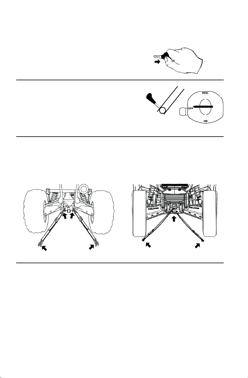
110
MAINTENANCE AND LUBRICATION
Transporting the Vehicle
Follow these procedures when
transporting the vehicle.
1. Turn the engine off. Remove the
key to prevent loss during transporting.
2. Place the transmission in
PARK.
3. Turn the fuel valve off
(if equipped).
4. Be sure the fuel cap, oil cap and seat are installed correctly.
5. Attach the FRAME of the vehicle to the transporting unit securely
using suitable straps or rope. Do not attach tie straps to the front
A-arm bolt pockets.
H
N
P
L
R

111
POLARIS PRODUCTS
Part No. Description
Engine Lubricant
2870791 Fogging Oil (355 ml Aerosol)
2871281 Premium 4 Synthetic 0W-40 (4-Cycle) Engine Oil (.95 l)
2871844 Premium 4 Synthetic 0W-40 (4-Cycle) Engine Oil (3.8 l)
Gearcase / Transmission Lubricants
2873602 Premium AGL Synthetic Gearcase Lube (.95 l)
2873603 Premium AGL Synthetic Gearcase Lube (3.8 l)
2871653 Premium ATV Angle Drive Fluid (237 ml)
2872276 Premium ATV Angle Drive Fluid (.95 l)
2870465 Pump for 3.8 liter jug
2871654 Premium Demand Drive Hub Fluid (237 ml)
2872277 Premium Demand Drive Hub Fluid (9.5 l)
Grease / Specialized Lubricants
2871322 Premium All Season Grease (89 ml cartridge)
2871423 Premium All Season Grease (414 ml cartridge)
2871460 Starter Drive Grease
2871515 Premium U-Joint Lube (89 ml)
2871551 Premium U-Joint Lube (414 ml)
2871312 Grease Gun Kit
2871329 Dielectric Grease (Nyogelt)
2872073 Chain Lube (185 ml aerosol)
2872348 Chain Lube (473 ml aerosol)
Coolant
2871323 60/40 Coolant (3.8 l)
2871534 60/40 Coolant (.95 l)
Additives / Miscellaneous
2872889 Brake and Clutch Cleaner
2871326 Carbon Clean Plus (355 ml)
2870652 Fuel Stabilizer (473 ml)
2870990 DOT3 Brake Fluid
2872893 Engine Degreaser
2871956 LOCTITE 565 Thread Sealant

112
SPECIFICATIONS
SPORTSMAN 500 / 500 EFI INT’L
Gross Vehicle Weight 1200 lbs./544 kg
Towing Rating 1225 lbs./556 kg
Unbraked Trailer Towing
Capacity*
1786 lbs. (810 kg)
Hitch Tongue Capacity
(Off-Road use only)
120 lbs./54 kg (Rear rack weight and tongue
weight not to exceed 180 lbs./81.6 kg)
Front Rack/Storage Box Capacity 90 lbs./40.8 kg
Rear Rack/Storage Box Capacity 180 lbs./81.6 kg
Overall Length 83 in./211 cm
Overall Width 48 in./122 cm
Overall Height 48 in./122 cm
Wheelbase 50.5 in./128.3 cm
Ground Clearance 11.25 in./28.6 cm
Dry Weight 730 lbs./331 kg (500)
745 lbs./338 kg (500 EFI)
Minimum Turning Radius 65 in./165 cm
Fuel Capacity 4.25 gal./16 l (500)
4.13 gal./15.6 l (500 EFI)
Engine Oil Capacity 2qts./1.9l
Coolant Capacity 2.25 qts./2.13 l
Engine EH500PLE137 (500)
EH500PLE210 (500 EFI)
Displacement 498
Bore x Stroke 92x75
Pilot Jet (500) 40
Main Jet (500) 155
Needle Jet (500) X-6M
Jet Needle (500) 6MGHI 194-3
Pilot Screw (500) 2 Turn (Brass plug)
Carburetor (500) 40mm CV Mikuni
Alternator Output 260 w (500)
350 w (500 EFI)
Compression Ratio 10.2:1 Full Stroke
Ignition System CDI (500)
Electronic (500 EFI)
Ignition Timing 30 BTDC @ 5000 RPM (500)
13 +/-- 3 BTDC @ 1150 RPM w/Engine warm
(500 EFI)
SparkPlug/Gap NGK BKR6E / .035 in. (0.9 mm)
* Based on EU Directive 76/432/EC

113
SPECIFICATIONS
SPORTSMAN 500 / 500 EFI INT’L
Lubrication System Dry Su mp
Driving System Type Automatic PVT (Polaris Variable Transmission)
Shift Type Side Lever (H/L/N/R/P)
Gear Reduction - Low 23.91/1
Gear Reduction - Reverse 16.30/1
Gear Reduction - Forward 10.49/1
Drive Ratio - Front 3.82/1
Tire, Front KendaBearclaw25x8-12(5psi)
Tire, Rear Kenda Bearclaw 25 x 10 - 12 (5 psi)
Foot Brake All-wheel hydraulic disc
Hand Brake Rear-wheel hydraulic disc
Parking Brake Transmission park lock and hydraulic lock, all
wheel
Front Suspension MacPherson Strut with 8.2” (20.8 cm) of travel
Rear Suspension Progressive Rate with 9.5” (24.1 cm) of travel
Shock Adjustment Rear Spring Preload Adjust
Headlights Hi/Lo35w
Taillights 8.26 w
Brakelight 26.9 w
Instrument Cluster LCD

114
SPECIFICATIONS
Jetting Chart (500)
Altitude AMBIENT
TEMPERATURE
Below 40° F
Below 5° C
+40° F and above
+5° C and above
Meters
(Feet)
0-1800
(0-6000)
160 155
(
)
1800-3700
(6000-12000)
152.5 147.5
Clutching Chart (500)
Altitude Shift
Weight
Drive Clutch
Spring
Driven Clutch
Spring
Helix and
Spring
Setting
Meters
(Feet)
0-1800
(0-6000)
10 WH
PN 5630710
Blue/Green
PN 7041 157
Black
PN 7041782
41-37°
PN 5132344
2+2
1800-3700
(6000-12000)
10 RH
PN 5630709
Blue/Green
PN 7041 157
Black
PN 7041782
41-37°
PN 5132344
2+2
Clutching Chart (500 EFI)
Altitude Shift
Weight
Drive Clutch
Spring
Driven Clutch
Spring
Helix*
Meters
(Feet)
0-1800
(0-6000)
10 WH
PN 5630710
Blue/Green
PN 7041 157
White/Yellow
PN 7041635
EBS
PN 5131674
(
)
1800-3700
(6000-12000)
10 RH
PN 5630709
Blue/Green
PN 7041 157
White/Yellow
PN 7041635
EBS
PN 5131674
*EBS models require no helix / spring adjustment

115
TROUBLESHOOTING
Drive Belt and Cover Problems
Possible Cause Solution
Driving the vehicle onto a
pickup or tall trailer in
high range.
Shift transmission to low range during loading of the
vehicle to prevent belt burning.
Starting out going up a
steep incline.
When starting out on an incline, use low range, or dis-
mount the vehicle and perform the K-turn as described on
page 30.
Driving at low RPM or
low ground speed (at
approximately 3-7 MPH).
Drive at a higher speed or use low range more frequently.
The use of low range is highly recommended for cooler
PVT operating temperatures and longer component life.
Insufficient warm-up of
vehicles exposed to low
ambient temperatures.
Warm the engine at least 5 minutes. With the transmission
in park, advance the throttle to about 1/8 throttle in short
bursts, 5 to 7 times. The belt will become more flexible
and prevent belt burning.
Slow and easy clutch en-
gagement.
Use the throttle quickly and effectively for efficient en-
gagement.
Towing/pushing at low
RPM/low ground speed.
Use low range only.
Utility use/plowing snow,
dirt, etc.
Use low range only.
Stuck in mud or snow. Shift the transmission to low range, and carefully use fast,
aggressive throttle application to engage clutch.
WARNING: Excessive throttle may cause loss of control
and vehicle overturn.
Climbing over large ob-
jects from a stopped posi-
tion.
Shift the transmission to low range, and carefully use fast,
brief, aggressive throttle application to engage clutch.
WARNING: Excessive throttle may cause loss of control
and vehicle overturn.
Belt slippage from water
or snow ingestion into the
PVT system.
Shift the transmission to park. Using the throttle, vary the
engine RPM from idle to full throttle. Repeat several
times as required. During this procedure, the throttle
should not be held at the full position for more than 10
seconds. Clutch seals should be inspected for damage if
repeated leaking occurs.
Clutch malfunction. Contact your Polaris dealer for inspection of clutch com-
ponents.
Poor engine performance. Check for fouled plugs or foreign material in gas tank,
fuel lines, or carburetor. Contact your dealer for service.

116
TROUBLESHOOTING
Contact your Polaris dealer for service if you’re unable to identify
solutions using the following charts.
Engine Does Not Rotate
Possible Cause Solution
Tripped circuit breaker Reset circuit breaker
Low battery voltage Recharge battery to 12.5 VDC
Loose battery connections Check all connections and tighten
Loose solenoid / starter connections Check all connections and tighten
Engine Rotates, Fails to Start
Possible Cause Solution
Out o f fuel Refuel
Clogged fuel valve or filter Inspect and clean or replace
Water is present in fuel Drain the fuel system and refuel
Fuel valve is turned off (if equipped) Turn the fuel valve to “RES”
Old or non-recommended fuel Replace with new fuel
Fouled or defective spark plug(s) Inspect plug(s), replace if necessary
No spark to spark plug Inspect plug(s), verify stop switch is on
Crankcase filled with water or fuel Immediately see your Polaris dealer
Overuse of choke (if equipped) Inspect, clean and/or replace spark plugs
Clogged fuel filter Replace the filter
Low battery voltage Recharge battery to 12.5 VDC
Mechanical failure See your Polaris dealer
Engine Overheats
Possible Cause Solution
Debris lodged in screen Remove and clean the screen. Pull on the
top portion of the screen, then remove the
lower portion.
Plugged Radiator Use a garden hose to flush any debris
from the radiator fins. NOTE: High pres-
sure washers can deform the radiator fins
and reduce cooling efficiency .

117
TROUBLESHOOTING
Engine Runs Irregularly, Stalls or Misfires
Possible Cause Solution
Fouled or defective spark plugs Inspect, clean and/or replace spark plugs
Worn or defective spark plug wires See your Polaris dealer
Incorrect spark plug gap or heat range Set gap to specs or replace plugs
Loose ignition connections Check all connections and tighten
Water present in fuel Replace with new fuel
Low battery voltage Recharge battery to 12.5 VDC
Kinked or plugged fuel vent line Inspect and replace (if equipped)
Incorrect fuel Replace with recommended fuel
Clogged air filter Inspect and clean or replace
Reverse speed limiter malfunction See your Polaris dealer
Electronic throttle control malfunction See your Polaris dealer
Other mechanical failure See your Polaris dealer
Possible Lean Fuel Mixture Cause Solution
Low or contaminated fuel Add or change fuel, clean the fuel system
Low octane fuel Replace with recommended fuel
Clogged fuel filter Replace filter
Kinked or plugged fuel tank vent line Inspect and replace (if equipped)
Incorrect jetting (if equipped) See your Polaris dealer
Possible Rich Fuel Mixture Cause Solution
Overuse of choke (if equipped) Inspect, clean and/or replace spark plugs
Fuel is very high octane Replace with lower octane fuel
Incorrect jetting (if equipped) See your Polaris dealer
Stopping/starting without adequate warm-
up
Allow engine to warm up before operat-
ing and/or stopping
Clogged air filter Inspect and clean or replace
Engine Pings or Knocks
Possible Cause Solution
Poor quality or low octane fuel Replace with recommended fuel
Incorrect ignition timing See your Polaris dealer
Incorrect spark plug gap or heat range Set gap to specs or replace plugs

118
TROUBLESHOOTING
Engine Backfires
Possible Cause Solution
Weak spark from spark plugs Inspect, clean and/or replace spark plugs
Incorrect spark plug gap or heat range Set gap to specs or replace plugs
Old or non-recommended fuel Replace with new fuel
Loose ignition connections Check all connections and tighten
Water present in fuel Replace with new fuel
Incorrectly installed spark plug wires See your Polaris dealer
Incorrect ignition timing See your Polaris dealer
Mechanical failure See your Polaris dealer
Engine Stops or Loses Power
Possible Cause Solution
Out o f fuel Refuel
Kinked or plugged fuel vent line Inspect and replace (if equipped)
Water present in fuel / old fuel Replace with new fuel
Overuse of choke (if equipped) Inspect, clean and/or replace spark plugs
Fouled or defective spark plugs Inspect, clean and/or replace spark plugs
Worn or defective spark plug wires See your Polaris dealer
Incorrect spark plug gap or heat range Set gap to specs or replace plugs
Loose ignition connections Check all connections and tighten
Low battery voltage Recharge battery / Check charging system
Incorrect fuel Replace with recommended fuel
Clogged air filter Inspect, clean or replace
Reverse speed limiter malfunction See your Polaris dealer
Electronic throttle control malfunction See your Polaris dealer
Other mechanical failure See your Polaris dealer
Overheated engine Clean radiator screen and core if equipped
Clean engine exterior
See your Polaris dealer

119
WARRANTY
LIMITED WARRANTY
Polaris Industries Inc., 2100 Highway 55, Medina, MN 55340, gives a TWO YEAR LIM-
ITED WARRANTY on all componentsof the PolarisQuadricycle againstdefects in materi-
al or workmanship. This warranty covers the parts and labor charges for repair or
replacement of defective parts which are covered by this warranty . This warranty begins on
thedate of purchase. This warranty istransferrableto anotherconsumerduring thewarranty
period through a Polaris dealer.
REGISTRATION
At the time of sale, the Warranty Registration Form must be completed by your dealer and
submitted to Polaris within ten days. Upon receipt of this registration, Polaris will record
the registration for warranty. THE PURCHASER MUST COMPLETE A QUADRI-
CYCLE SAFETY TRAINING COURSE PROVIDED BY THE DEALER IN ORDER
TO HAVE VALID WARRANTY ON THE QUADRICYCLE. No verification of registra-
tion will be sent to the purchaser as the copy of the Warranty Registration Form will be the
warranty entitlement. If you have not signed the original registration and received the “cus-
tomer copy”, please contact your dealer immediately. NO WARRANTY COVERAGE
WILL BE ALLOWED UNLESS YOUR QUADRICYCLE IS REGISTERED WITH PO-
LARIS.
Initial dealer preparation and set-up of your vehicle is very important in ensuring trouble-
free operation. Purchasing a machine in the crate or without proper dealer set-up will void
your warranty coverage.
LIMITATIONS OF WARRANTIES AND REMEDIES
The Polaris limited warranty excludes any failures that are not caused by a defect in material
or workmanship. This warranty does not cover accidental damage, normal wear and tear,
abuse or improper handling. This warranty also does not cover any Quadricycle that has
been altered structurally, modified, neglected, improperly maintained, used for racing, or
used for purposes other than for which it wasmanufactured, orfor any damages whichoccur
during trailer transit or as a result of unauthorized service or the use of unauthorized parts.
In addition, this warranty does not cover physical damage to paint or finish, stress cracks,
tearing or puncturing of upholstery material, corrosion, or defects in parts, components or
the vehicle due to fire, explosions or any other cause beyond Polaris’ control.
This warranty does not cover the use of unauthorized lubricants, chemicals, or fuels that are
not compatible with the Quadricycle. The exclusive remedy for breach of this warranty shall
be, at Polaris’ exclusive option, repair or replacement of any defective materials, or compo-
nents or products. THE REMEDIES SET FORTH IN THIS WARRANTY ARE THE
ONLY REMEDIES AVAILABLE TO ANY PERSON FOR BREACH OF THIS WAR-
RANTY. POLARIS SHALL HAVE NO LIABILITY TO ANY PERSON FOR INCIDEN-
TAL, CONSEQUENTIAL OR SPECIAL DAMAGES OF ANY DESCRIPTION,
WHETHER ARISING OUT OF EXPRESS OR IMPLIED WARRANTY OR ANY OTH-
ER CONTRACT, NEGLIGENCE, OR OTHER TORT OR OTHERWISE. Some states do
not permit the exclusion or limitation of incidental or consequential damages or implied
warranties, so the above limitations or exclusions may not apply to you if inconsistent with
controlling state law.

120
WARRANTY
LIMITATIONS OF WARRANTIES AND REMEDIES
ALL IMPLIED WARRANTIES (INCLUDING BUT NOT LIMITED TO THE IMPLIED
WARRANTIES OF MERCHANTABILITY AND FITNESS FOR A PARTICULAR
PURPOSE) ARE LIMITED IN DURATION TO THE ABOVE TWO YEAR WARRAN-
TY PERIOD. POLARIS FURTHER DISCLAIMS ALL EXPRESS WARRANTIES NOT
STATED IN THIS WARRANTY. Some states do not allow limitations on how long an im-
plied warranty lasts, so the above limitation may not apply to you if inconsistent with con-
trolling state law.
HOW TO OBTAIN WARRANTY SERVICE
Ifyour Quadricyclerequires warranty service, you must take it to aPolaris dealer authorized
to repair Polaris Quadricycles. When requesting warranty service you must present your
copy of the Warranty Registration form to the dealer. (THE COST OF TRANSPORTA-
TION TO AND FROM THE DEALER IS YOUR RESPONSIBILITY). Polaris suggests
that you use youroriginal selling dealer; however, you may use any Polaris Servicing Dealer
to perform warranty service.
Please work with your dealerto resolve any warranty issues. Should your dealer requireany
additional assistance they will contact the appropriate personnel at Polaris.
Thiswarranty gives you specificlegal rights,and you may also have otherrightswhich vary
from state to state.
If any of the above terms are void because of state or federal law , all other warranty terms
will remain in effect.

121
MAINTENANCE LOG
Use the following chart to record periodic maintenance.
DATE MILES (KM) TECHNICIAN SERVICE PERFORMED / COMMENTS

122
MAINTENANCE LOG
DATE MILES (KM) TECHNICIAN SERVICE PERFORMED / COMMENTS

123
MAINTENANCE LOG
DATE MILES (KM) TECHNICIAN SERVICE PERFORMED / COMMENTS

124
INDEX
A
Age Restriction 7..................
Air Filter 91......................
AWD Operation 45................
AWD Switch 40...................
B
Battery 103-105...................
Battery Fluid 105..................
Battery Installation 104.............
Battery Removal 104...............
Battery Storage 105, 107............
Belt Break-in 55...................
Belt Life 48......................
Brake Fluid 80-81..................
Brake Lever 41...................
Brake, Foot 42....................
Brake, Parking 43.................
Brake, Rear 42....................
Brakes 42-43, 80-82................
Break-In Period 55.................
C
Carburetor 85.....................
Cargo 36-37......................
Cleaning the Vehicle 106............
Clutch Break-in 55.................
Clutching Chart (500 EFI) 114.......
Clutching Chart (500) 114...........
Cold Weather Operation 59..........
Controls 38-41....................
Coolant Level, Bottle 78............
Coolant Level, Radiator 79..........
Cooling System 79................
D
Diagnostic Mode 53-54..............
Drivetrain Break-in 55..............
Driving Downhill 32...............
Driving in Reverse 33..............
Driving on Slippery Surfaces 25......
Driving Over Obstacles 26...........
Driving Procedures 23..............
Driving Safely 23-35................
Driving Through Water 34-35.........
Driving Uphill 28-29...............
E
Electromagnetic Interference 62.......
Electronic Throttle Control 40........
Emission Control Systems 62........
E
Engine Break-in 55................
Engine Cooling System 78..........
Engine Fogging 108...............
Engine Stop Switch 39.............
Equipment Modifications 8..........
ETC 40.........................
Exhaust Emission Control System 62..
Eye Protection 22..................
F
Foot Brake 42....................
Footwell Removal 88...............
Fuel Filter 47.....................
Fuel Safety 46....................
Fuel Stabilizer 107.................
Fuel Tank 47.....................
Fuel Valve 47.....................
G
Gear Selector 48...................
Gearcase Oil Change, Front 77.......
Gearcase Oil Check, Front 76........
H
Handlebar Adjustment 84...........
Hauling Cargo 36-37................
Hazard Warning 41................
Headlight Beam Adjustment 95.......
Headlights 92.....................
Helmet 22.......................
High Range 60....................
Horn 41.........................
Hour Meter 52....................
I-J-K
Immersion 98-99...................
Instrument Cluster 50-54.............
Instruments 38-41..................
Jetting Chart (500) 114.............
K-Turn 30.......................
L
Lamp Replacement
Front Turn Signal 94...........
Headlight 92.................
Rear Turn Signal 93............
Taillight 93...................
Light Switch 39...................
Lights 92-95......................

125
INDEX
L
Load Distribution 37...............
Low Range 60....................
Lubrication Recommendations 67.....
M
Main Switch 38...................
Maintenance Chart Key 63...........
Making Turns 24..................
Master Cylinder (Foot Brake) 81......
Master Cylinder (Handlebar) 81.......
Mirrors 40.......................
N
Noise Emission Control System 62....
O
Odometer 52.....................
Oil Change 70-73..................
Oil Check 69.....................
Oil Filter Change 70-73.............
Oil Pump Priming 73...............
Oil, Engine 68....................
Operator Safety 6-17................
Override Switch 39................
P
Parking Brake 43..................
ParkingonanIncline 35............
Periodic Maintenance Chart 63-66.....
Polaris Products 111...............
Pre Ride Inspection 56..............
PVT Break-in 55..................
PVT Drying 61...................
PVT System 60-61.................
R
Rear Brake Lever 42...............
Rear Spring 90....................
Recoil Housing 102................
Recoil Starter 49..................
Restrictions 8.....................
Rider Information Center 51-54.......
Riding Gear 22...................
S
Safe Riding Gear 22................
Safety Decals and Locations 18-21.....
Safety Training 7..................
Severe Use 63....................
S
Side Panel Removal 87.............
Sidehilling 27....................
Signal Light, Front 94..............
Signal Light, Rear 93...............
Spark Arrestor 62, 100-101...........
Spark Plugs 96-97..................
Specifications 112-113..............
Speedometer Mode Switch 39........
Startin g a Cold Engine 57-58.........
Starting a Warm Engine 59..........
Starting the Engine 57-59............
Steering 83.......................
Steering Assembly 84..............
Steering Lock 44..................
Stop Switch 39....................
Storing the Vehicle 107-109..........
Suspension 83....................
Symbol Identification 67............
T
Tachometer 52....................
Taillight 93.......................
Throttle Cable Freeplay 86...........
Throttle lever 38..................
Tire Tread Depth 90................
Tires 90.........................
Toe Alignment 83.................
Torque Symbol 67.................
Towing 36-37.....................
Transmission 60...................
Transmission Oil Change 75.........
Transmission Oil Check 74..........
Transporting the Vehicle 110.........
Trip Meter 52.....................
Troubleshooting 115-118............
Turn Signal 41....................
Turn Signal Indicator 41............
Turning Around on a Hill 30-31.......
V
Vehicle Identification Numbers 5......
Vehicle Immersion 98-99............
W
Warranty 119-120..................
Waxing the Vehicle 106.............
Wheel Hub Tightening 90...........
Wheel Installation 89...............
Wheel Removal 89................