Loading ...
Loading ...
3
Unit Voltage
Rating Minimum Maximum
230/280 187 253
115 103 126
Voltage Utilization Range
Operating Voltage
INSTALLATION INSTRUCTIONS
To ensure that the unit operates safely and efficiently, it must be
installed, operated, and maintained according to these installa-
tion and operating instructions and all local codes and ordinances,
or, in their absence, with the latest edition of the National Electrical
Code. The proper installation of this unit is described in the follow-
ing sections. Following the steps in the order presented should
ensure proper installation.
SLEEVE INSTALLATION
In order for condensate water to drain properly inside the unit, the
sleeve must be installed properly:
• Level from right to left.
• A slight downward pitch from the indoor side to the outdoor
side as shown in Figure 3.
Refer to the Installation Instructions supplied with the wall sleeve
for a complete description of the installation procedure.
NOTE: Wall sleeve (PBWS01A ) is not shipped with chassis and
must be purchased separately.
Wall
Sleeve
Outside
Wall
OutsideInside
Level
1/4 Bubble
Tilt To
Outside
Figure 2
REAR LOUVER PANEL
A TWKG rear louver panel kit is required for unit installation into an
existing Amana
®
brand 26” wall sleeve. A TWEAK or TWFAK adapter
kit is required for unit installation into an existing 27” wall sleeve.
The rear louver panel directs air flow for proper unit operation and
protects the outdoor coil. The panel must be installed before in-
stalling the chassis. These kits are not supplied with the unit.
Refer to the Installation Instructions supplied with the rear louver
panel kit for a complete description of the installation procedure.
CHASSIS INSTALLATION
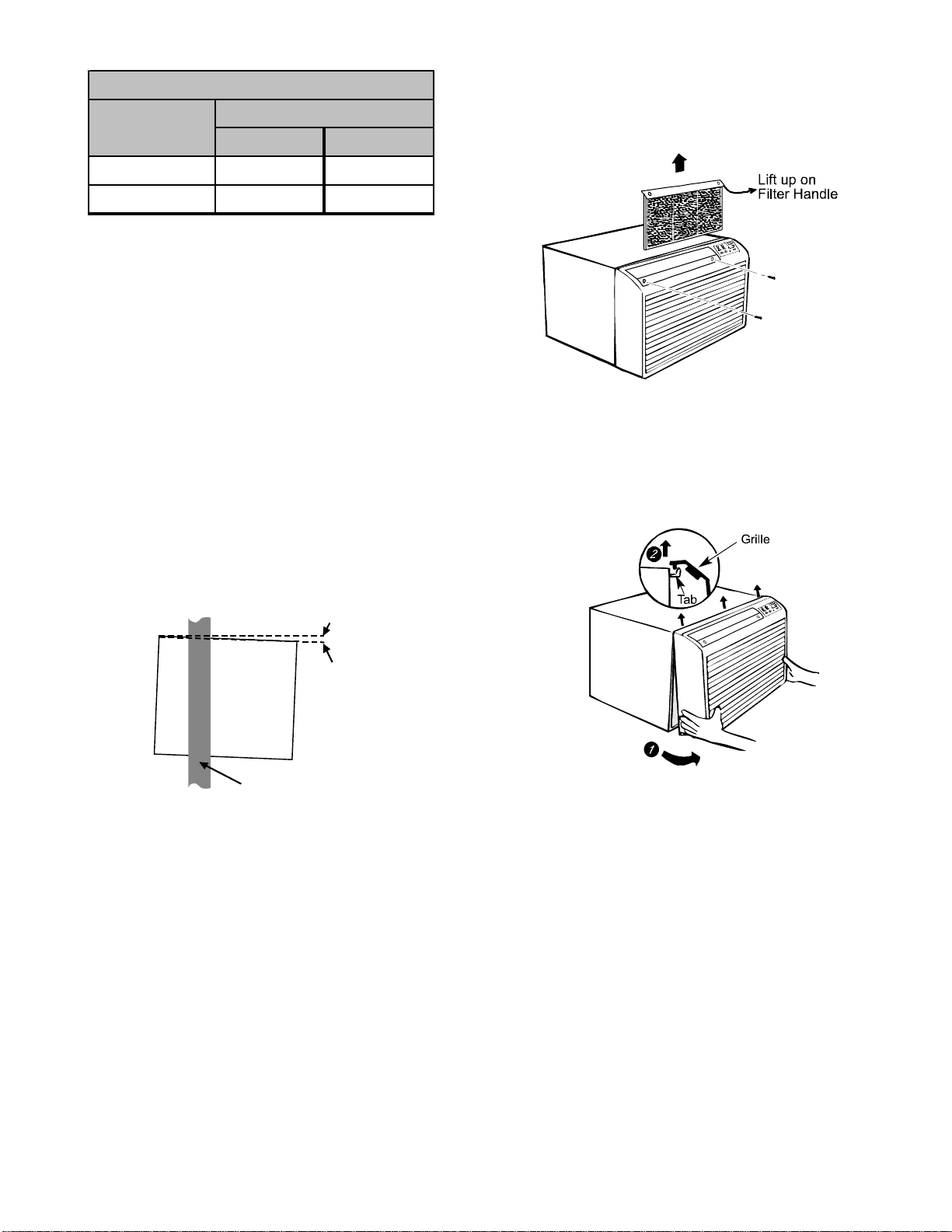
1. Remove front grille. See Figure A.
Figure A
The front grille can be removed for more thorough cleaning or to
make the model and serial numbers accessible. To remove, pull
the filter out and remove the two grille screws.
Pull the grille out from the bottom and lift up from the tabs on the
top of the case.
2. Remove the grounding screw and wire next to the grounding
symbol on right side of chassis control panel (Figure 3). At-
tach other end of ground wire to the hole in the bottom right
side of the sleeve with #8 x 3/8” blunt point sheet metal screw.
The hole on the sleeve is indicated by grounding symbol on
the sleeve. Slide chassis part of the way into the sleeve and
reattach the ground wire back to the hole on the right side on
the control panel area next to the grounding symbol.
Loading ...
Loading ...
Loading ...