Loading ...
Loading ...
Loading ...
9
GBDFEINLPGRRUTRCZSVHGPO
Warning:
When installing and moving the unit, do not charge it with refrigerant other
than the refrigerant specified on the unit.
- Mixing of a different refrigerant, air, etc. may cause the refrigerant cycle to mal-
function and result in severe damage.
Caution:
• Use refrigerant piping made of C1220 (Cu-DHP) phosphorus deoxidized
copper as specified in the JIS H3300 “Copper and copper alloy seamless
pipes and tubes”. In addition, be sure that the inner and outer surfaces of
the pipes are clean and free of hazardous sulphur, oxides, dust/dirt, shav-
ing particles, oils, moisture, or any other contaminant.
•Never use existing refrigerant piping.
- The large amount of chlorine in conventional refrigerant and refrigerator oil
in the existing piping will cause the new refrigerant to deteriorate.
• Store the piping to be used during installation indoors and keep both
ends of the piping sealed until just before brazing.
- If dust, dirt, or water gets into the refrigerant cycle, the oil will deteriorate and
the compressor may fail.
7.2. Drain piping work
• Ensure that the drain piping is downward (pitch of more than 1/100) to the
outdoor (discharge) side. Do not provide any trap or irregularity on the way.
• Ensure that any cross-wise drain piping is less than 20 m (excluding the differ-
ence of elevation). If the drain piping is long, provide metal braces to prevent it
from waving. Never provide any air vent pipe. Otherwise drain may be ejected.
• Use a hard vinyl chloride pipe O.D. ø32 for drain piping.
• Ensure that collected pipes are 10 cm lower than the unit body’s drain port.
• Do not provide any odor trap at the drain discharge port.
• Put the end of the drain piping in a position where no odor is generated.
•
Do not put the end of the drain piping in any drain where ionic gases are generated.
[Fig. 7.2.1] (P.3)
A Downward slope 1/100 or more
B Drain hose (Accessory)
C Indoor unit
D Collective piping
E Maximize this length to approx. 10 cm
1. Insert the drain hose (accessory) into the drain port.
(The drain hose must not be bent more than 45° to prevent the hose from
breaking or clogging.)
The connecting part between the indoor unit and the drain hose may be dis-
connected at the maintenance. Fix the part with the accessory band, not be
adhered.
2. Attach the drain pipe (O.D. ø32 PVC TUBE, field supply).
(Attach the pipe with glue for the hard vinyl chloride pipe, and fix it with the
band (small, accessory).)
3. Perform insulation work on the drain pipe (O.D. ø32 PVC TUBE) and on the
socket (including elbow).
[Fig. 7.2.2] (P.3)
A Indoor unit
B Insulation pipe (short) (accessory)
C Tie band (accessory)
D Band fixing part
E Insertion margin
F Drain hose (accessory)
G Drain pipe (O.D. ø32 PVC TUBE, field supply)
H Insulating material (field supply)
I Max.145 ± 5 mm
7. Connecting refrigerant pipes and drain pipes
7.1. Refrigerant piping work
This piping work must be done in accordance with the installation manuals for both
outdoor unit.
•For constraints on pipe length and allowable difference of elevation, refer to
the outdoor unit manual.
• The method of pipe connection is brazing connection.
Caution:
• Install the refrigerant piping for the indoor unit in accordance with the
following.
1. Cut the tip of the indoor unit piping, remove the gas, and then remove the
brazed cap.
[Fig. 7.1.1] (P.3)
A Cut here
B Remove brazed cap
2. Pull out the thermal insulation on the site refrigerant piping, braze the unit
piping, and replace the insulation in its original position.
Wrap the piping with insulating tape.
Note:
• When blazing the refrigerant pipes, be sure to blaze, after covering a wet
cloth to the pipes of the units in order to prevent it from burning and
shrinking by heat.
[Fig. 7.1.2] (P.3)
A Cool by a wet cloth
•Pay strict attention when wrapping the copper piping since wrapping the
piping may cause condensation instead of preventing it.
[Fig. 7.1.3] (P.3)
A Thermal insulation tubing (small)
B Caution:
Pull out the thermal insulation on the refrigerant piping at the site, braze the pip-
ing, and replace the insulation in its original position.
Ta ke care to ensure that condensation does not form on exposed copper piping.
C Refrigerant piping (liquid)
D Refrigerant piping (gas)
E Main body
F Thermal insulation tubing (large)
G Site refrigerant piping
H Ensure that there are no gaps between the insulation and the main body.
I Thermal insulation tubing (small) (supplied) 1
J Ties (large) (supplied) 4
K Ensure that there is no gap here. Place join upwards.
L Thermal insulation tubing (medium) (supplied) 2
M Thermal insulation
N Pull
O Flared pipe end
P Wrap with damp cloth
Q Return to original position
R Ensure that there is no gap here.
Cautions On Refrigerant Piping
ss
ss
s Be sure to use non-oxidative brazing for brazing to ensure that no for-
eign matter or moisture enter into the pipe.
ss
ss
s Be sure to apply refrigerating machine oil over the flare connection seat-
ing surface and tighten the connection using a double spanner.
ss
ss
s Provide a metal brace to support the refrigerant pipe so that no load is
imparted to the indoor unit end pipe. This metal brace should be pro-
vided 50 cm away from the indoor unit’s flare connection.
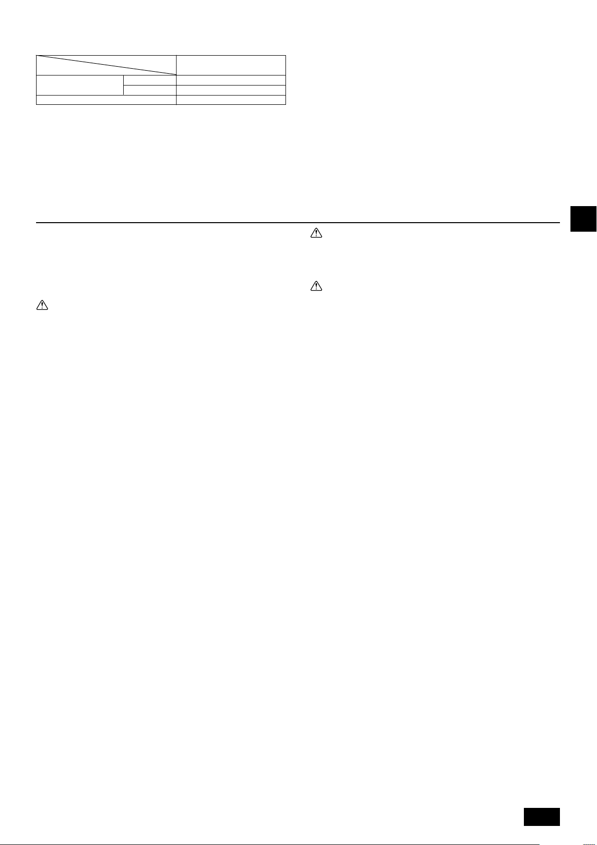
6.1. Refrigerant pipe and drain pipe specifications
Refrigerant pipe
(Brazing connection)
Model
Item
250
Liquid pipe ø 9.52
Gas pipe ø 22.2
Drain pipe O.D. ø 32
6.2. Refrigerant pipe, drain pipe
[Fig. 6.2.1] (P.2)
A Air inlet B Refrigerant piping (liquid)
C Refrigerant piping (gas) D Control box
E Drain pipe F Air outlet
WT05750X01_GB.p65 09/10/19, 16:309
Loading ...
Loading ...
Loading ...