Loading ...
Loading ...
Loading ...
5
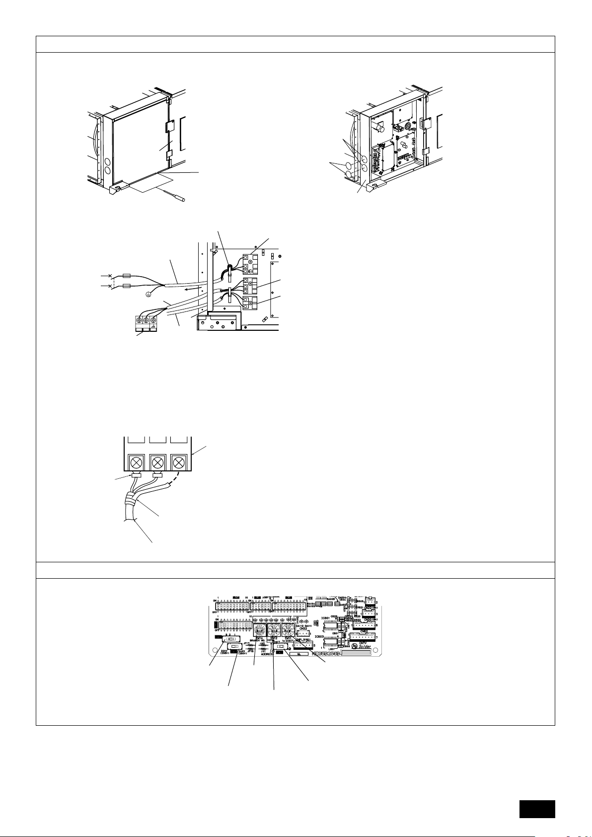
I Power source terminal bed
J Te rminal bed for indoor transmission
K Te rminal bed for remote controller
L To 1-phase power source
M Transmission line DC 30 V
N Te rminal bed for outdoor transmission line (TB3)
O Transmission line to the remote controller
A Ter minal bed
B Round terminal
C Shield wire
D Insulation tape (To keep the earth wire of the shielded cable from coming in contact with the transmis-
sion terminal)
9.3
[Fig. 9.5.1]
[Fig. 9.3.4]
9.5
A Te r minal bed box
B Knockout hole
C Remove
[Fig. 9.3.1] [Fig. 9.3.2]
B
C
A
A
B
I
J
F
G
E
L
N
12
L
S
M2
M1
K
H
O
N
M
L
N
M2
M1
M2 SM1
A
B
C
D
A Screw holding cover (2pcs)
B Cover
SWA
SW5
SW14
SW12
SW11
SWC
<Indoor controller board>
[Fig. 9.3.3]
E Use PG bushing to keep the weight of the cable and external force from being
applied to the power supply terminal connector. Use a cable tie to secure the
cable.
Wind the wire around the cable strap once to keep it from being pulled out.
F Power source wiring
G Tensile force
H Use ordinary bushing
WT05750X01_illust.p65 09/11/6, 14:175
Loading ...
Loading ...
Loading ...