Operating Instructions
Features
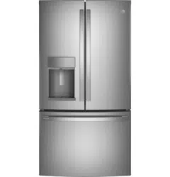
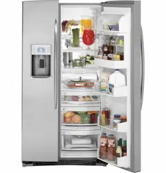
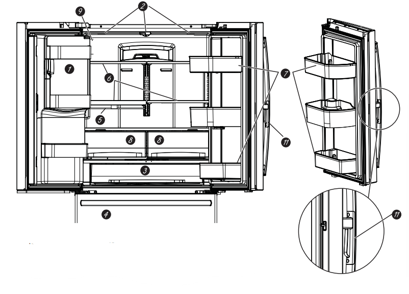
 Space-saving ice maker*
lce maker and bin are located on the door creating more usable storage space.
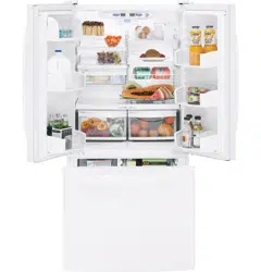
 Showcase LED lighting
LED lighting is positioned throughout the interior to spotlight areas in the refrigerator. LEDs are located under the refrigerator door to light the freezer when opened.
�
 Drop-down tray*
Allows for extra door storage when you need it and tucks away when you don’t.
 Full-width temperature controlled drawer
Adjustable temperature control bin that can accommodate larger items.
 Dairy bin
Separate compartments for your items.
 Ice bin/Ice maker*
Ice maker with ice storage bins.
 QuickSpace™ shelf*
Functions as a normal full-sized shelf when needed and easily slides back to store tall items below.
 Spillproof shelves
Designed to capture your spills for easier clean up.
 Anti-slip Mat
Liner that captures spills, keeps containers from shifting when the door is opened and is easily removable for cleaning.
 Removable door bin
Can be removed for those with a wall limiting the door opening.
 Climate zone bin
Separate bins for produce storage.
 Water filter
Filters water and ice.
�
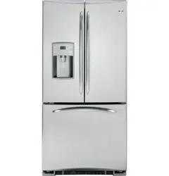
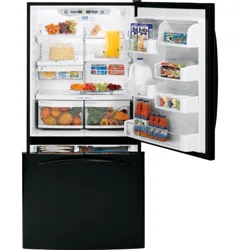
Scace-saving ice maker*
lce maker and bin are located on the door creating more usable storage space.
Showcase LED lighting
LED lighting is positioned throughout the interior to spotlight areas in the refrigerator. LEDs are located under the refrigerator door to light the freezer when opened.
Full-width temperature controlled drawer
Adjustable temperature control bin that can accommodate larger items.
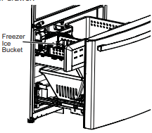
Freezer Ice maker/Ice Bin*
An ice maker in both compartments give you more ice whenever you need it. Available on Non-Dispense models, also available as a kit for some models
QuickSpace™ shelf*
Functions as a normal full-sized shelf when needed and easily slides back to store tall items below
 Spillproof shelves
Designed to capture your spills for easier clean up.
 Removable door bin
Can be removed for those with a wall limiting the door opening.
 Climate zone bin
Separate bins for produce storage.
 Water filter
Filters water and ice.
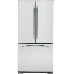
 Rotating Bin*
Can be rotated out for easy access.
 Door in Door Latch*
Squeeze the latch on the underside of the handle to open the outer door.
Door ice bin*
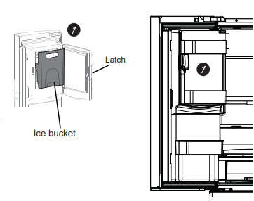
1. Open left refrigerator door.
2. Pull down latch to release bin door.
3. Using handhold lift ice bucket up and out to clear locators in bottom of bin
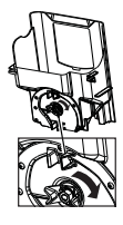
4. To replace the ice bucket, set it on the guide brackets and push until the ice bucket seats properly.
5. If bucket cannot be replaced, rotate the Ice Bucket Fork 1/4 turn clockwise.
�
Ice/water filter
Certified to reduce chlorine-resistant cysts, lead, replacement instructions see page 17.
�
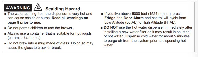
�WARNING 
Use of the hot water dispenser prior to purging air from the system may result in spurting of hot water and lead to hot water scalding. Follow the instructions for “Water Filter - Step 3" on page 17 to purge all air from the system through the cold water dispenser prior to using the hot water dispenser.
The first time the hot water feature is used, confirm if you live above 5000 feet (1524 meters) (high altitude. This limits the temperature of the hot water system to avoid boiling. To access the high altitude selection, see Controls.
Controls
NOTE: The refrigerator is shipped with protective film covering the temperature controls. If this film was not removed during installation, remove it now.
The temperature controls are preset in the factory at 37°F for the refrigerator compartment and 0°F for the freezer compartment. Allow 24 hours for the temperature to stabilize to the preset recommended settings.
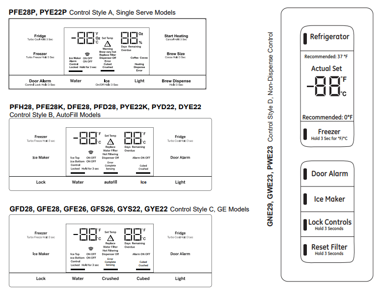
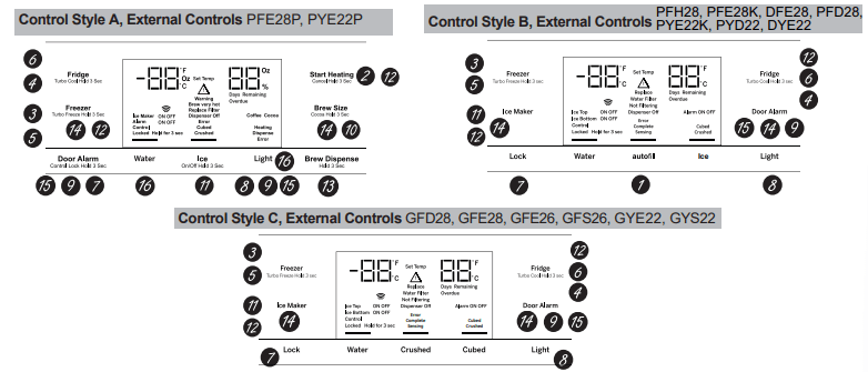
Control Style D: The temperature controls can display both the SET temperature as well as the actual temperature in the refrigerator and freezer. The actual temperature may vary slightly from the SET temperature based on usage and operating environment (PWE23, GWE23, and GNE29 only).
�
Changing the Temperature for Control Style A
To Change the Refrigerator Temperature:
Press the Fridge button and current set temperature will display. Pressing and releasing the button will cycle through the available temperature settings. Press and hold button for Turbo Cool feature. The display will show tC.
To Change the Freezer Temperature:
Press the Freezer button and current set temperature will display. Pressing and releasing the button will cycle through the available temperature settings. Press and hold button for Turbo Freeze feature. The display will show tF.
Cooling system can be turned off by pressing and holding Freezer and Start Heating. OFF will be displayed. To turn on, press Fridge or Freezer. ON will be displayed. Turning the cooling system off stops the cooling to the refrigerator, but it does not shut off the electrical power.
Changing the Temperature for Control Styles B and C
To change the temperature, press and release the Freezer or Fridge pad. The display will show the set temperature. To change the temperature, press either the Freezer or Fridge pad until the desired temperature is displayed. Press and hold button for Turbo Cool feature. The display will show tC. Press and hold button for Turbo Freeze feature. The display will show tF.
To turn off the cooling system press and hold the Fridge and Ice Maker buttons. To turn on, press Fridge or Freezer.
Turning the cooling system off stops the cooling to the refrigerator, but it does not shut off the electrical power.
Changing Temp. for Control Style D
Temperature Display is located on inside of left-hand refrigerator door. To change the temperature, press and release the REFRIGERATOR or FREEZER pad. The ACTUAL TEMP light will come on and the
display will show the actual temperature. To change the temperature, tap either the REFRIGERATOR or
FREEZER pad until the desired temperature is displayed.
To turn OFF cooling system, press and hold the REFRIGERATOR and FREEZER pads simultaneously for 3 seconds. When cooling system is OFF the display should read OF. To turn ON cooling system, press either REFRIGERATOR or FREEZER pad. The display will show the preset temperature settings of 37°F (3°C for refrigerator and 0°F (-18°C) for freezer.
Turning the cooling system off stops the cooling to refrigerator, but it does not shut off the electrical power.
NOTE: For optimal temperature performance, we recommend to avoid placing food items directly at the air flow vents of the refrigerator air tower and thus blocking the air flow.
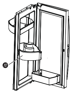
 Hands-free Autofill*
Hands-free Autofill* Hands-free Autofill uses sensors to monitor container height to automatically dispense filtered water without having to activate the paddle.
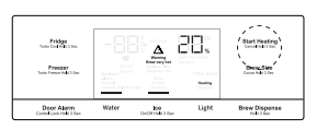
 Start Heating*
The Start Heating button is used to initiate the water heating for the Single Serve feature. To abort the Start Heating feature, press and hold the Start Heat button for 3 seconds.\
 Freezer temp control
Adjust freezer compartment temperature.
 Refrigerator temp control
Adjust refrigerator compartment temperature.
 TurboFreeze™ setting
Activate TurboFreeze to quickly restore freezer temperatures after frequent door openings.
 TurboCool™ setting
Activate TurboCool to quickly restore refrigerator temperature after frequent door openings.
 Lock Controls
Control Style A - Press and hold the Door Alarm pad for 3 seconds to lock out ice and water dispenser and all feature and temperature buttons.
Control Styles B & C - Press Lock pad and hold 3 seconds to lock out ice and water dispenser and all feature and temperature buttons.
 Dispenser light
Lighting that can be turned on/off to light your dispenser.
 Door Alarm
Sounds to alert when the freezer or refrigerator doors have been left open. Press and hold Door Alarm pad and it will toggle the sound between low, high, and off.
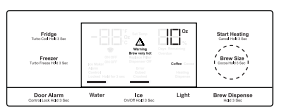
 Brew Size*
The Brew Size button is used to select the desired cup size for single serve. Press and hold the button for 3 seconds to toggle the brew type between Coffee and Cocoa.
 Ice maker setting
Tum your ice makers on/off.
 Cooling system On/Off
Control Style A - Press and hold Freezer and Start Heating simultaneously to turn cooling system off. To turn cooling system on press either the Fridge or Freezer.
Control Style B & C - Press and hold Fridge and Ice Maker simultaneously for 3 seconds to turn the cooling system off. To turn cooling system on press either the Fridge or Freezer.
 Brew Dispense
Press and hold Brew Dispense button for 3 seconds, but no longer than 6 seconds, to dispense coffee or cocoa.
 F°/C°
F°/C°
Control Style A - Press and hold Freezer and Brew Size to switch between F°/C*
Control Style B & C - Press and hold Ice Maker and Door Alarm simultaneously for 3 seconds to switch between F°/C°.
�
 Sound Control for pad chimes
Control Style A - Press and hold the Light pad: Once for High to Off, twice for Off to Low and three times for Low to High.
Control Styles B & C - Press and hold the Door Alarm pad: Once for High to Off, twice for Off to Low and three times for Low to High.
 High Altitude
Control Style A (PYE and PFE only) - Press and hold Fridge and Door Alarm for to toggle between Hi Al and Lo AL for high altitude and low altitude.
Additional settings:
- Connected Home ready” (PFE28P, PYE22P, PFH only)
- Water Filter’ - An indicator will illuminate when the filter, needs to be replaced. When a new filter is installed the indicator will go off
Additional Mode:
Control Style A - Press and hold Alarm and Light simultaneously for 3 seconds to enter/exit Sabbath mode. Control Style B & C - Press and hold Lock and Light simultaneously for 3 seconds to enter/exit Sabbath mode. Sabbath Mode will turn off or dim interior lights, temperature control and advanced features. Compressor will run on a timed defrost when in Sabbath mode.
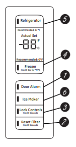
 Door Alarm
Sounds to alert when the freezer or refrigerator doors have been left open.
 Reset Filter
Hold for 3 seconds after replacing filter.
 Lock Controls
Press and hold 3 seconds to lock out ice and water dispenser and all feature and temperature buttons.
 Freezer temp control
Adjust freezer compartment temperature
 Refrigerator temp control
Adjust refrigerator compartment temperature
 Ice maker setting
Tum your ice maker on/off.
Additional Mode:
Press and hold Door Alarm and Ice Maker simultaneously for 3 seconds to enter/exit Sabbath mode.
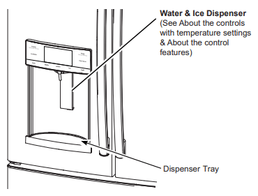
Dispenser*
WARNING Laceration Hazard
- Never put fingers or any other object into ice crusher discharge opening. Doing so can result in contacting the ice crushing blades and lead to serious injury or amputation
- Use a sturdy glass when dispensing ice. A delicate glass may break and result in personal injury.
If no water is dispensed when the refrigerator is first installed. there may be air in the water line system. Press the dispenser paddle for at least five minutes to remove trapped air from the water line and to fill the water system. To flush out impurities in the water line. throw away the first six full glasses of water.
To remove Dispenser Tray (Type A and B Only)
- Pull Dispenser Tray out until it stops
- Locate tab in the center on the bottom and push up
- Pull Dispenser Tray assembly out.
- Lift Dispenser Tray out at center notch to clean.
To remove Dispenser Tray (Type C Only)
- Grasp Dispenser Tray and pull firmly until it comes out.
To reinstall Dispenser Tray (Type A and B Only)
- Place the Dispenser Tray cover on top of catch tray and position under the two plastic retainers on either side
- Center Dispenser tray. and align with center guides
- Push in until it locks firmly in place.
To reinstall Dispenser Tray (Type C Only)
- Line up the guide on tray bottom with track on dispenser and slide it in until it stops against the back of the dispenser.
Important Facts About Your Dispenser
- Do not add ice from trays or bags to the door ice maker bucket. It may not crush or dispense
- Avoid overfiling glass with ice and use of narrow glasses. Backed-up ice can jam the chute or cause the door in the chute to freeze shut. If ice is blocking the chute remove the ice bucket. poke it through with a wooden spoon.
- Beverage and foods should not be quick-chilled in the door ice maker bin. Cans. bottles or food packages in the storage drawer may cause the ice maker or auger to jam.
- To keep dispensed ice from missing the glass. put the glass close to. but not touching. the dispenser opening.
- Some crushed ice may be dispensed even though you selected CUBED ICE. This happens occasionally when a few cubes accidentally get directed to the crusher
- After crushed ice is dispensed. some water may drip from the chute
- Sometimes a small mound of snow will form on the door in the ice chute. This condition is normal and usually occurs when you have dispensed crushed ice repeatedly. The snow will eventually evaporate.
To Use the Internal Water Dispenser*
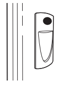
The water dispenser is located on | the left wall inside the refrigerator compartment.
To dispense water:
1 Hold the glass against the recess.
2 Push the water dispenser button.
3 Hold the glass underneath the dispenser for 2-3 seconds after releasing the dispenser button.
Water may continue to dispense after the button is released.
If no water is dispensed when the refrigerator is first installed. there may be air in the water line system. Press the dispenser button for at least 5 minutes to remove trapped air from the water line and to fill the water system. During this process. the dispenser noise may be loud as the air is purged from the water line system. To flush out impurities in the water line. throw away the first
6 glassfuls of water.
NOTE: To avoid water deposits. the dispenser should be cleaned periodically by wiping with a clean cloth or sponge.
AUTOFILL*
To Use HANDS FREE AUTOFILL:
-
Center container on Recess Dispenser Tray as far back as possible without activating paddle and remove hand from container
- Press AUTOFILL
To Stop AUTOFILL
Important Facts about AUTOFILL
- For optimum results. use a uniform container between 4-8" (10-20 om) tall and 2-6” (5-15 om) wide
- Fill level and functionality may vary on containers taller than 8" (20 cm) or wider than 6” (15 cm)
- Container volumes may vary. if error message "Not. Found’ is given. try a different container
- AUTOFILL will time out
- Handles. straws. and gamishes on the rim of the container my cause overfiling or variation in fill volumes.
- Splashing may occur depending on the location of the container. water flow rate. container shape. and ice cubes.
- Keep sensors clean with a clean damp cloth. and do not spray liquid or cleaners directly on sensors
- AUTOFILL works best with household water pressure of 60 to 100 psi (414 to 689 kPa)
- Ice in container may affect fill volume. If issues are experienced. use less ice.

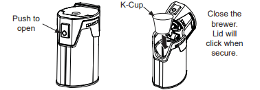
Single Serve Keurig K-Cup Brewer*
Important Facts about HOT WATER
How to use the single serve dispenser
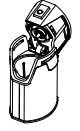
1 Load the K-Cup Brewer
Insert a Keurig K-Cup pod into the brewer and press down firmly (you will hear a popping sound).
CAUTION Cut/Puncture Hazard.
- There are two sharp needles located inside the K-Cup brewer. To avoid risk of injury, do not put your fingers inside the brewer. Use caution when cleaning.
- Keep the K-Cup brewer out of the reach of children, as they may be injured in using the K-Cain hewer incorrect
2 Two Ways To Brew
1. Press the Start Heating button
OR
2. Initiate heating with the GE Kitchen App. Download the App “GE Kitchen”. Visit GEAppliances.com/connect for more information.**
3 Change Brew Size
Press the Brew Size button any time during the heating cycle to choose 6, 8, or 10 oz. The default size is 8 oz. Ensure the mug being used is large enough for the size selected.
NOTE: Press and hold the Brew Size button for 3 seconds to toggle between Coffee and Cocoa. The default is Coffee.
NOTE: To abort the heating cycle, press and hold the Start Heating button for 3 seconds. To abort the brew dispense cycle, press and hold the Start Heating button for 3 seconds, press the paddle, press any button on the display besides Brew Size or Brew Dispense, or open the right refrigerator door.
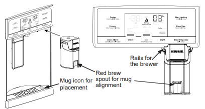
4 Dispense
Once the heating process is complete, the Dispense light on the display will flash.
To dispense, slide the brewer into the rails. Make sure the brewer is pushed all the way into the bracket. Place your mug on the drip tray mug icon, under the red brew spout. Press and hold Brew Dispense for 3 seconds until you hear the dispenser engage.
Cleaning the brewer
- The K-Cup brewer is top rack dishwasher safe.
- It is recommended to rinse it thoroughly after washing to remove all soap residue.
- Periodic cleaning of dispenser recess area is recommended as staining may occur with usage
- of the K-Cup brewer.
Appliance Communication
GE WiFi Connect**
(for customers in the United States, its territories, and Canada)
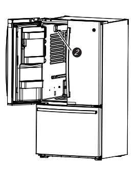
GE WiFi Connect Enabled* (PFE28P, PFD28, PYD22, PYE22P, PFH models only)
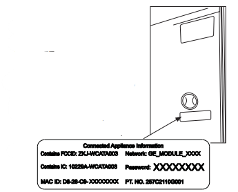
If your refrigerator has a Connected Appliance information label located on the inside as shown, your refrigerator can be connected to your WiFi network, allowing it to communicate with your smartphone for remote monitoring, control, and notifications. Depending on the refrigerator model you have, you either have a WiFi communication card built into the product or a port for an external WiFi ConnectPlus Module (sold separately).
�
Please visit GEAppliances.com/connect to learn more about connected appliance features, and to leam what connected appliance apps will work with your Smart Phone.**
To use your WiFi, press Water and Light on the control panel.
GE WiFi Connect Optional *
You refrigerator is GE WiFi Connect compatible using the GE ConnectPlus module that is provided with your refrigerator. To connect this appliance to the internet you will need to attach the module to your appliance through the communication port in the appliance. The GE ConnectPlus will allow your appliance to communicate with your smart phone for remote appliance monitoring. control and notifications. Please visit GEAppliances.com/connect to learn more about connected appliance features. to learn what connected appliance App’s will work with your Smart.
Phone and to learn where you can purchase a GE ConnectPlus.*
WiFi Connectivity: For assistance with the appliance or the ConnectPlus network connectivity (for models that are WiFi enabled or WiFi optional). please call 1-800-220-6899.
REGULATORY INFORMATION
FCC/IC Compliance Statement:
This device complies with Part 15 of the FCC Rules. Operation is subject to the following two conditions:
1. This device may not cause harmful interference.
2. This device must accept any interference received. including interference that may cause undesired operation.
This equipment has been tested and found to comply with the limits for a Class B digital device. pursuant to Part 15 of the FCC Rules. These limits are designed to provide reasonable protection against harmful interference in a residential installation. This equipment generates uses and can radiate radio frequency energy and. if not installed and used in accordance with the instructions. may harmful interference to radio communications. However. there is no guarantee that interference will not occur in a particular installation. If this equipment does cause harmful interference to radio or television reception. which can be determined by turning the equipment off and on. the user is encouraged to try to correct the interference by one or more of the following measures:
- Reorient or relocate the receiving antenna.
- Increase the separation between the equipment and receiver.
- Connect the equipment into an outlet on a circuit different from that to which the receiver is connected.
- Consult the dealer or an experienced radio/television technician for help.
Labeling: Changes or modifications to this unit not expressly approved by the manufacturer could void the user's authority to operate the equipment.
ConnectPlus module only (or similar communication module)
RF Exposure - This device is only authorized for use in a mobile application. At least 20 cm of separation distance between the ConnectPlus device and the user's body must be maintained at all times.
Water Filter Cartridge - RPWFE
Water Filter Cartridge
The water filter cartridge is located in the fresh food interior on the left side wall, near the top.
Select models use radio frequency identification (RFID) to detect leaks and monitor filter status. The RFID technology is certified by the FCC.
FCCID: ZKJ-EBX1532P001
ICID: 102294-£BX1532P001
“This device complies with part 15 of the FCC Rules. Operation is subject to the following two conditions: (1) This device may not cause harmful interference, and (2) this device must accept any interference received, including interference that may cause undesired operation.”
“This device complies with Industry Canada license-exempt RSS standard(s). Operation is subject to the following two conditions: (1) this device may not cause Interference, and (2) this device must accept any interference, including interference that may cause undesired operation of the device.”
When to Replace the Filter Cartridge
The filter cartridge should be replaced every six months or earlier if 170 gallons (643.52 liters) of water has been dispensed or the flow of water to the dispenser or icemaker decreases.
Touch Screen Models: A filter status message will appear on the screen when the water filter needs to be replaced. The filter status will automatically update when the filter is replaced
Non-touch Screen Models: A filter indicator light will illuminate on the screen when the water filter needs to be replaced.
Removing the Filter Cartridge
DO NOT TWIST CARTRIDGE! Twisting may damage refrigerator or filter.
1. Remove the old cartridge by opening the filter door and pulling on the bottom of the cartridge to allow it to swing outward.
2. When the cartridge can no longer swing, gently pull to unseat from the cartridge holder. A small amount of water may drip out.
DO NOT TWIST CARTRIDGE!
Installing the Filter Cartridge
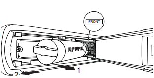
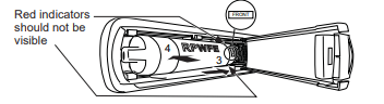
1. Center the cartridge with cartridge holder with the word FRONT facing outward. Push the cartridge inward until it is fully seated. FRONT should be centered with the cartridge holder for proper installation. The RED indicators should not be visible.
�
2. While continuing to ensure cartridge is fully seated in the holder, gently swing the filter inward until it is in Position. If filter will not swing easily, check to ensure filter is properly aligned and fully seated within the cartridge holder.
3. For dispenser models ~ Run 2 gallons of water through the cold water dispenser (about 5 minutes) to remove air from the system. A newly installed fitter cartridge will cause water to spurt from the dispenser. Use a large pitcher or sports bottle to catch the water spray. NOTE: It is normal for water to appear discolored during the initial system flush. Water color will return to normal after the first few minutes of dispensing.
For icemaker-only models Discard the first bin of ice to allow air to purge from the system. A newly installed filter cartridge will cause water to spurt into the icemaker body, which could lead to ice droplets around the icemaker area. NOTE: It is normal for these droplets and initial ice production to appear discolored during the initial system flush. Ice color will return to normal after the first bin of ice production. DO NOT use the hot water dispenser or Autofill function until all air is removed from the system.
6. Reset Filter status message (non-touch screen models).
�
�Filter Bypass Plug
To reduce the risk of property damage due to water
leakage, you MUST use the filter bypass plug when a replacement flter cartridge is not available. Some
models do not come equipped with the filter bypass plug. To obtain a free bypass plug, visit us on-line at geappliances.com/service. in Canada, visit geappliances.ca/service. The dispenser and icemaker will not operate without either the filter or the bypass plug installed. The bypass plug is installed in the same way as a filter cartridge.
WARNING 
Use of the hot water dispenser prior to purging air from the system may result in spurting of hot water and lead to hot water scalding. Follow the instructions above to urge all air from the system through the cold water dispenser prior to using the hot water dispenser.
�
WARNING To reduce the risk associated with choking, do not allow children under 3 years of age to have access to small parts during the installation of this product. This disposable filter cartridge should be replaced every 6 months at the rated capacity, or sooner if a noticeable reduction in flow rate occurs.
For the maximum benefit of your filtration system, GE Appliances, a Haier company, recommends the use of GE Appliances-branded filters only. Using GE Appliances-branded filters in GE Appliances refrigerators provides optimal performance and reliability. Our filters meet rigorous industry NSF standards for safety and quality that are important for products that are filtering your water. There is no assurance that brands other than
GE Appliances filters meet our standards for quality, performance and reliability.
If you have questions, or to order additional filter cartridges, visit gewaterfilters.com.In Canada, visit GEAappliances.ca/service or consult the yellow pages for the nearest Camco Service Center.
Refrigerator Storage Options
Rearranging the Shelves
Shelves in the refrigerator compartment are adjustable.
To remove:
Remove all items from the shelf.
Tilt the shelf up at the front.
Lift the shelf up at the back and bring the shelf out.
To replace:
While tilting the shelf up, insert the top hook at the back of the shelf in a slot on the track.
Lower the front of the shelf until the bottom of the shelf locks into place.
Spillproof Shelves
Spillproof shelves have special edges to help prevent spills from dripping to lower shelves.
Quick Space Shelf *
This shelf splits in half and slides under itself for storage of tall items on the shelf below.
This shelf can be removed and replaced or relocated (just like spillproof shelves)
NOTE: The back half of the Quick Space Shelf is not adjustable.
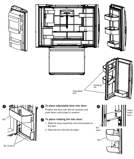
Refrigerator Storage Options
Right Door Bins
FIXED BINS can easily be carried from refrigerator to work area.
To remove: Lift bin straight up, then pull out.
ROTATING BIN*
To remove: Rotate bin outward then lift straight up. To remove Place hand under metal base and lift up.
To remove Metal Base: Place hand under metal base and lift up.
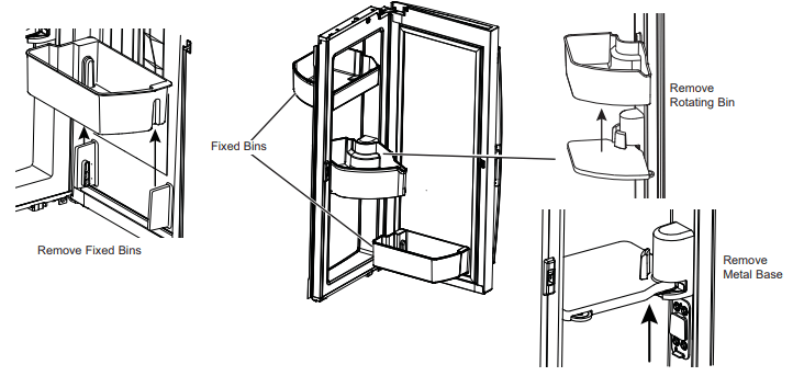
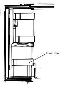
Left Door Bins
DISPENSER MODELS - FIXED BIN
To remove: Lift the bin straight up, then pull out.
The ice maker door bins are not interchangeable, note the location upon removal and replace the bin in its proper location.
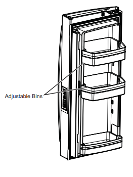
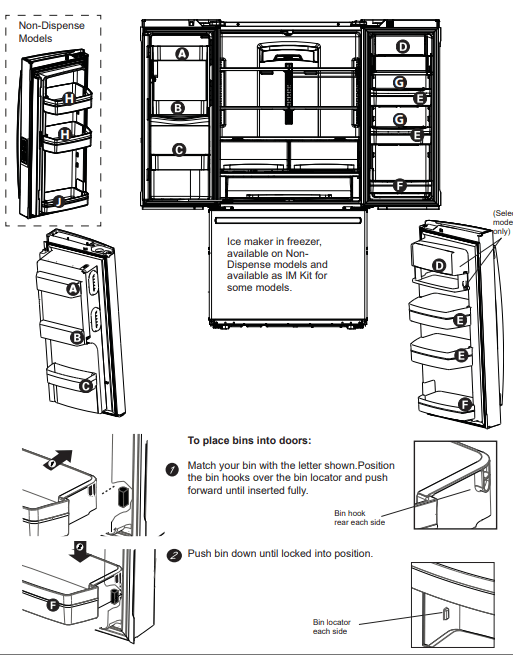
NON-DISPENSER MODELS - ADJUSTABLE BINS*
Adjustable bins can easily moved up or down the inside of the door to give better flexibility for storage.
To remove: Lift bin straight up, then pull out.
Climate Zone & Temperature Controlled Drawer
ClimateZone
Keep fruits and vegetables organized in separate compartments for easy access.
Excess water that may accumulate in the bottom of the drawers or under the drawers should be wiped dry.
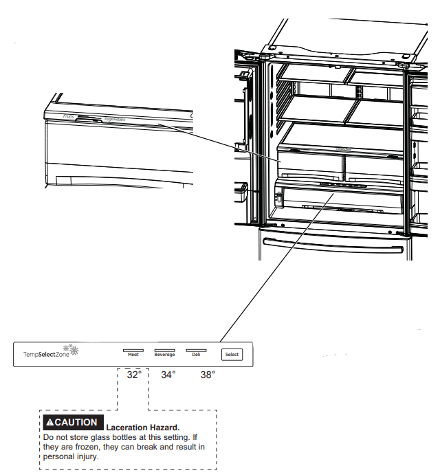
Temperature Controlled Drawer*
The Temperature Controlled Drawer is a full-width drawer with adjustable temperature control. This drawer can be used for large miscellaneous items.
To change setting, press select button.
Note: Temperatures indicate the appropriate temperatures for the food and actual temperatures may vary based on normal operation and other factors such as door openings and refrigerator set point.
Climate Zone & Temperature Controlled Drawer
How to Remove and Replace Drawer
To remove:
Pull the drawer out to the stop position.
Lift the front of the drawer up and out.
To replace:
Pull left and right slides until fully extended.
Place drawer back in first and rotate drawer front down to seat on slide.
Push the drawer in to closed position.
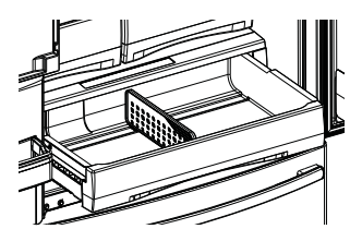
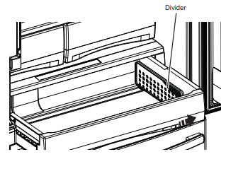
How to Remove and Replace Drawer Divider*
To remove:
Pull the drawer out to the stop position.
Raise the front side of the divider to unhook it from the rear wall of the drawer.
To replace:
Hook the back of the divider over the rear wall of the drawer.
Push the divider down.
Baskets, Drawers, and Bins
Freezer Basket and Drawer
Basket
Drawer
Ice Bucket * (Available on Non-Dispense models only. Available as a IM Kit on some models)
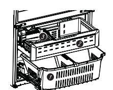
Non-Adjustable Bin in the Freezer*
To remove:
Push in plastic tab on either left or right side
To replace:
Slide bin into location until it locks into place
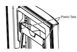
Basket Removal
To remove. standard depth models only:
1. Open freezer door to the stop positon.
2. Remove freezer door bin by pushing plastic tab on either left or right side to release bin hinge pin.
3. Remove freezer basket by lifting up the rear of the basket and moving basket rearward unti the front of the basket can be rotated upward and out.
4. Lift it out to remove.
To remove. counter depth models only:
1. Open refrigerator doors.
2. Open freezer door to the stop position.
3. Remove freezer basket by lifting up the rear of the basket and rotate it upward.
4. Lift it out to remove
To replace:
Reverse step 1 through 4 to replace.
Automatic Ice Maker
A newly installed refrigerator may take 12 to 24 hours to begin making ice.
WARNING Connect to potable water supply only.
A cold water supply is required for automatic icemaker operation. The water pressure must be between 40 and 120 psi (275-827 kilopascals).
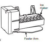
Automatic Ice maker*
The ice maker will produce seven cubes per cycle approximately 100-130 cubes in a 24-hour period. depending on freezer compartment temperature. room temperature, number of door openings and other use conditions.
The ice maker will fill with water when it cools to 15°F (-10°C). A newly installed refrigerator may take 12 to 24 hours to begin making ice cubes.
If the refrigerator is operated before the water line connection is made to the unit or if the water supply to an operating refrigerator is turned off. make sure that the ice maker is turned off. Once the water has been connected to the refrigerator. the ice maker may be turned on. See the table below for detal
You may hear a buzzing sound each time the ice maker fills with water.
Throw away the first bin of ice to allow the water line to clear. It is normal for ice to appear discolored in the first
24 hours of production. or after water filter replacement.
Be sure nothing interferes with the sweep of the feeler arm.
When the bin fills to the level of the feeler arm. the ice maker will stop producing ice. It is normal for several cubes to be joined together.
If ice is not used frequently. old ice cubes will become cloudy. taste stale and shrink.
NOTE: In homes with lower-than-average water pressure. you may hear the ice maker cycle multiple times when making one batch of ice.
CAUTION: To minimize the risk of personal injury. avoid contact with the moving parts ofthe ejector mechanism. or with the heating element that releases the cubes. Do not place fingers or hands on the automatic ice making mechanism while the refrigerator is plugged in.
How to Turn the Ice Maker On/Off
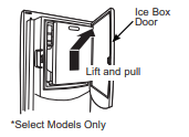
Ice Bucket and Dispenser*
- Open the ice box door on inside of the left door.
- Pull up and out on the ice bucket in the left hand door to remove it from the compartment .
- To replace the ice bucket, set it on the guide brackets and push until the ice bucket seats properly.
- If bucket cannot be replaced, rolate the ice bucket fork 1/4 turn clockwise.
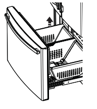
Ice Maker (Available on Non Dispense models, also available as IM Kit for some models)
There is additional ice storage in the freezer compartment drawer.
- Open the freezer drawer.
- The ice bucket is located on the left side of the upper freezer basket
- Pull the upper basket forward to remove the ice bucket
Care and Cleaning
Cleaning the Outside
FINGERPRINT RESISTANT STAINLESS STEEL*, BLACK STAINLESS, SLATE, DARK SLATE, PAINTED - Outside surfaces, door handles, and trim
DO NOT use Stainless Steel cleaners on the door surfaces.
IMPORTANT: The use of incorrect products may damage the outer finish of Fingerprint Resistant Stainless and
Black Stainless models. Please follow these instructions and use only the appropriate items below to clean your appliance surfaces.
- Clean interior/exterior surfaces with warm water. mild soap or detergent. and a soft or microfiber cloth to avoid damage.
- Wipe the appliance surface dry with a soft clean cloth or microfiber towel to avoid streaking or water spotting
DO USE
- Soft clean cloth or sponge
- Mild detergent mixed with warm water
DO NOT USE
- Abrasive cloths, paper towels, scrubbing sponges (with or without soap) scouring or steel wool pads
- Abrasive powders, liquids, or sprays
- Window sprays, ammonia, or bleach
- Citrus or plant oil-based cleaners
- Acidic or vinegar-based cleaners
STAINLESS STEEL - Outside surfaces, door handles, and trim
NOTE: DO NOT allow stainless steel cleaner to come in contact with any plastic parts such as trim pieces. handle hardware and liners. If unintentional contact of cleaners with plastic parts does occur. clean plastic part with a sponge and mild detergent mixed with warm water.
DO USE
- Soft, clean cloth or sponge
- Mild detergent mixed with warm water
- Approved stainless steel cleaners; Visit the GE Appliances parts store for approved stainless steel /cleaners: GEApplianceparts.com or call 877.959.8688.
- Cleaners with oxalic acid such as Bar Keepers Friend Soft [Cleanser can be used to remove surface rust. tarnish [and small blemishes on stainless steel surfaces only.
DO NOT USE
- Abrasive cloths, paper towels, scrubbing sponges (with or without soap) scouring or steel wool pads
- Abrasive powders or sprays
- Window Sprays or Ammonia
- Citrus or plant oil-based cleaners
- Acidic or vinegar-based cleaners
- Oven cleaners
- Cleaners containing acetone (propanone)
- Any cleaner with WARNING about plastic contact
Cleaning the Inside
To help prevent odors, leave an open box of baking soda in the refrigerator and freezer compartments.
Unplug the refrigerator before cleaning.
If this is not practical. wring excess moisture out of sponge or cloth when cleaning around switches. lights or controls.
Use an appliance wax polish on the inside surface between the doors.
Use warm water and baking soda solution—about a tablespoon (15 mi) of baking soda to a quart (1 liter) of water. This both cleans and neutralizes odors. Rinse and wipe dry.
To clean the inside metal panel*, open the outer door using the Door in Door Latch. Clean the panel with a mild detergent and then wipe dry with a soft cloth. Do not use any stainless steel cleaner on the panel as it may damage the surrounding plastic.
CAUTION
Do not clean glass shelves or coverswith warm water when they are cold. Glass shelves and covers may break if exposed to sudden temperature changes or impacts such as bumping or dropping. Tempered glass is designed to shatter into many small pieces it breaks.
Do not wash any plastic refrigerator parts in the dishwasher.
Behind the Refrigerator
Be careful when moving the refrigerator away from the wall. All types of floor coverings can be damaged, particularly cushioned coverings and those with embossed surfaces.
Raise the leveling legs located at the bottom front of the refrigerator.
Pull the refrigerator straight out and return it to position by pushing it straight in. Moving the refrigerator in a side direction may result in damage to the floor covering or refrigerator.
Lower the leveling legs until they touch the floor.
WARNING 
When pushing the refrigerator back, make sure you don’t roll over the power cord or water supply line.
Preparing for Vacation
For long vacations or absences, remove food and unplug the refrigerator. Clean the interior with a baking soda solution of one tablespoon (15 ml) of baking soda to one quart (1 liter) of water. Leave the doors open.
If the temperature can drop below freezing, have a qualified service technician drain the water supply system to prevent serious property damage due to flooding.
1. Turn refrigerator off or unplug the refrigerator.
2. Empty ice bucket
3. Turn water supply off.
If you cut the water supply off, turn off the ice maker.
Upon retuming from vacation:
1. Replace the water filter.
2. Run 2 gallons (7.57 liters) of water through the cold water dispenser (about 5 minutes) to flush the system.
Preparing to Move
Secure all loose items such as shelves and drawers by taping them securely in place to prevent damage
When using a hand truck to move the refrigerator, do not rest the front or back of the refrigerator against the hand truck. This could damage the refrigerator.
Handle only from the sides of the refrigerator.
Be sure the refrigerator stays in an upright position during moving.
Replacing the Lights
Refrigerator Lights (LEDs)
Appearance may vary by model.
There is LED lighting in refrigerator compartment and on the bottom of the refrigerator doors to light the freezer compartment. *
An authorized technician will need to replace the LED light
If this assembly needs to be replaced, call GE Appliances Service at 1.800.432.2737 in the United
Slates or 1.800.561.3344 in Canada,
Installation Instructions
Refrigerator
GE and GE Profile™ models
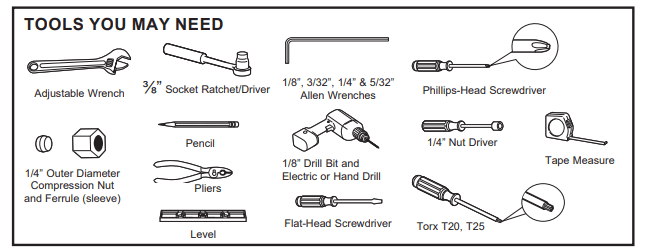
BEFORE YOU BEGIN
Read these instructions completely and carefully.
WARNING 
Built-in style models (model PYE, GYE, GYS, GWE, PYD PWE, and ZWE) are top heavy. especially with any doors open. These models must be secured with the anti-tip floor bracket to prevent tipping forward. which could result in death or serious injury. Read and follow the entire installation instructions for installing the anti-tip floor bracket packed with your refrigerator.
- IMPORTANT — observe all governing codes and ordinances. Save these instructions for local inspectors' use.
- Note to Installer — Be sure to leave these instructions with the Consumer.
- Note to Consumer — Keep these instructions for future reference.
- Skill level — Installation of this appliance requires basic mechanical sill
- Completion time — Refrigerator installation can vary. Water Line Installation 30 minutes
- Proper installation is the responsibility of the install.
- Product failure due to improper installation is not covered under the Warranty.
PREPARATION
MOVING THE REFRIGERATOR INDOORS
If the refrigerator will not fit through a doorway, the refrigerator door and freezer drawer can be removed.
- To remove the refrigerator door, see the Installing the Refrigerator section.
- To remove the freezer drawer, see the Removing the Freezer Drawer section.
WATER SUPPLY TO THE ICE MAKER AND DISPENSER
If the refrigerator has an ice maker, it will have to be connected to cold water line. A GE Appliances water supply kit (containing tubing, shutoff valve, fittings and instructions) is available at extra cost from your dealer, by visiting our website at GEAppliances.com (in Canada at GEAppliances.ca) or from Parts and Accessories,
888.959.8688 (in Canada 1.800.661.1616).
MOVING THE REFRIGERATOR
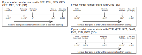
- Using the chart below determine if the width of your passageway can accommodate the depth of the refrigerator. Ensure you have clearance to prevent damage to the refrigerator before safely moving it to the final location.
- If passageways are large enough to accommodate the refrigerator without removing the handles skip to Step 6.
Leave tape, film, and all packaging on doors until the refrigerator is in the final location.
- NOTE: Use a padded hand truck or moving straps to move this refrigerator. Place the refrigerator on the hand truck with a side against the truck. We strongly recommend that two people move and complete installation.
INSTALLING THE REFRIGERATOR
REFRIGERATOR LOCATION
Do not install the refrigerator where the temperature will go below 60°F (16°C) because it is not run often enough to maintain proper temperatures.
Do not install the refrigerator where the temperature will go above 100°F (37°C) because it will not perform properly
Do not install the refrigerator in a location exposed to water (rain, etc.) or direct sunlight.
Install It on a floor strong enough to support it fully loaded.
CLEARANCES
�
Allow the following clearances for ease of installation, proper air circulation and plumbing and electrical connections.
Sides 1/8" (3 mm)
Top 1" (25mm) CabinetHinge Cover
Back 2" (50mm)
REMOVING THE REFRIGERATOR DOORS
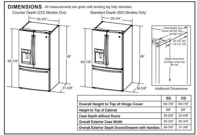
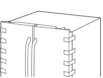
- IMPORTANT NOTE: This refrigerator is 34.375" deep without handles (29.375" for CD models). Doors and passageways leading to the installation location must be at least 34.375" wide (29.375" for CD models) in order to leave the doors attached to the refrigerator while transporting it into the installation location. If passageways are less than 34.375" wide (29.375" for CD models) the refrigerator doors can easily be scratched and damaged. The top cap and doors can be removed to allow the refrigerator to be safely moved indoors. If passageways are less than 34.375" wide (29.375" for CD models), start with Step 1
- If it is not necessary to remove doors, skip to Step 11. Leave tape and all packaging on doors until the refrigerator is in the final location.
- NOTE: Use a padded hand truck to move this refrigerator. Place the refrigerator on the hand truck with a side against the truck. We strongly recommend that TWO PEOPLE move and complete this installation.
1 REMOVE REFRIGERATOR DOORS
WARNING Follow all steps for removing and reinstalling the door. Failure to follow these instructions, leaving off parts, or overtightening screws, can lead to the door falling off and result in injury and property damage.
A) Securely tape the door shut with masking tape or have a second person support the door.
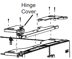
B) Start with left-hand door first: Remove the hinge cover on top of the left refrigerator door by removing all hex screws and pulling it up. Do the same for the right-hand door and the middle cover.
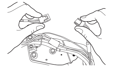
C) Disconnect electrical connectors coming from each door located under the hinge covers.
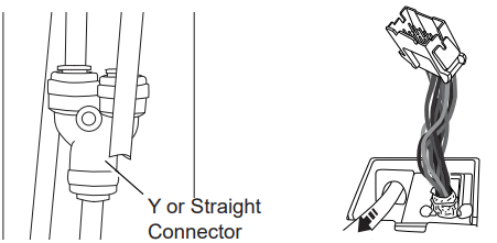
D) On some models, disconnect the water line from the back of the unit by pressing down on the dark grey collar while pulling up on the water line. Pull water line through case conduit from the top to free the line for door removal. The water line is more than 4’ long and may need to be taped to Door for accessibility when reinstalling.
E)Using a 3/8" socket ratchet/driver, remove the screws securing the top hinge to the cabinet.
CAUTION Lifting Hazard
Single person lift could cause injury. Use assistance when handling, moving or lifting the doors.
NOTE: when removing door, to prevent damage to door and electronics, carefully place the door in a proper location.
NOTE: The lower door hinge pin and hinge are keyed and must be matched correctly for the door to self close properly. Please follow the directions carefully.
NOTE: For proper installation later, please follow the next step carefully
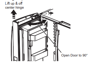
F) Remove the tape and keeping the door as straight as possible, open the door to 90º then lift straight up to remove it.
REMOVE OPPOSITE DOOR
Follow the same procedure on the opposite door. There are no water lines on the opposite side.
For Door in Door Models: Securely tape the inner and outer doors before installing or removing. 90º door alignment not required during installation or removal for these models.
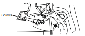
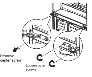
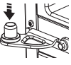
G) REMOVE CENTER HINGE (if necessary)
Remove screws that secure hinge to the cabinet. Inner 4” screw need either 3/8", Philips #2, or T27. Outer #8 small screws require Torx 20 or %4" drive.
�
2 REINSTALLING THE REFRIGERATOR DOORS
Reverse steps 1 through 4 to reinstall refrigerator doors, follow details below for critical alignments.
Reinstall center hinge first and torque the 14" screw to 65 in-tbs
(7.34 N-m) and small screw to 25 in-lbs (2.82 N-m). Rotating the sorew by 1/3 tum after it is flush with mating surface will achieve these torques.
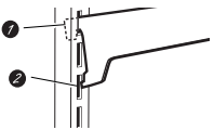
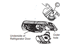
B) If the hinge on your refrigerator has a slot that looks like image B on the right, follow the steps below. Otherwise, skip to step C

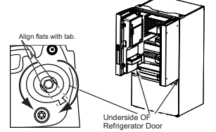
With the LH door at 90° + to the front of the case, lower the refrigerator door. Ensure the door and hinge align correctly. Rotate door closed and make sure moveable center sealing portion of the door aligns with the striker. If door cannot be installed at 90°, follow these next steps. Install door at 90° to case front. If space or model limits opening door to less than 180°, remove door and carefully turn door upside down. Check alignment of door closure mechanism shaft on underside of door. The flats on the shaft should correspond to alignment tab on plastic ring on bottom end cap. If shaft is not aligned to tab, using 5/32" Allen wrench, rotate door closure
mechanism shaft counterclockwise for right door and clockwise for left door. Then align flat with tab. Install the door at 90°.
�
�
C) If the hinge on your refrigerator does not have a slot and looks like image C on the right, then simply lower the outer hole of the door on the hinge pin.
D) Securely tape the door shut with masking tape or have a second person support the door.
E) Follow the same procedure to install the opposite door. There are no wires, water lines, or center hinge covers on the opposite door.
F) Be sure to reinstall the ground wire and strain relief to the top hinge.
G) Reinstall hinge cover. NOTE: Ensure wires are not pinched or under screw bosses before tightening screws.
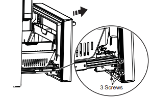
3 REMOVE THE FREEZER DOOR
A) Pull the freezer door open to full extension.
B) Remove 3 attachment screws, located at the bottom on each side of the freezer door using 3/8" hex socket driver.
�
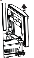
CAUTION Lifting Hazard Freezer door is heavy Use both hands to secure the door before lifting.
C) Lift the freezer door to disengage it from the slide mechanism
The door can safely rest on the bottom Do not rest the door on any other surfaces to avoid soratches.
�
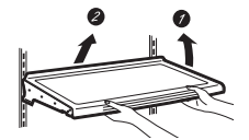
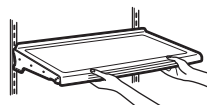
4 REMOVE FREEZER BASKET
A) Pull the lower basket and slide mechanism to full extension using both hands.
B) Remove the top freezer drawer by fully extending the drawer then lifting up and out
C) Remove the basket resting on the slides.
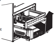
D) Push the bottom basket slides back until the slide mechanism self retracts.
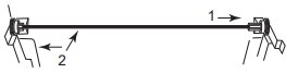
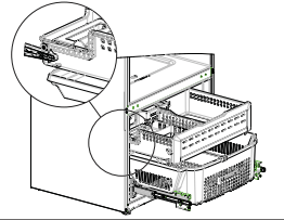
5 REMOVE THE FREEZER BASKET SLIDES
The freezer basket slides can be removed to gain another 3/4” (1.90 cm) clearance through a doorway.
A) Remove freezer door as shown in Step 6.
B) Remove the upper and lower baskets as shown in Step 7.
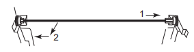
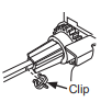
C) Remove the clip on the crossbar,cated along the right hand side of the rack and pinion gear assembly by sliding forward.

D) Remove crossbar by sliding to the right, then pull out and to the left.
�
�
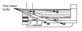
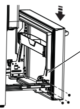
E) Remove the four 1/4” hex head bots par side and remove side supports.
F) Reverse the steps to assemble. When installing the crossbar always put the hole on the right hand side. Align the left and right gears with the timing marks on the gears when inserting the crossbar. Always insert the crossbar in the right hang gear first and then the left hand gear.
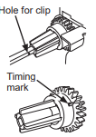
G) Inset the clip into the crossbar hole located on the right hand side.
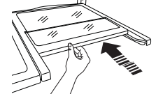
6 RE-INSTALL FREEZER DRAWER
A) Re-install freezer drawer by placing the drawer wheels onto the top of the track mounted to the side of the freezer walls. The wheels on the freezer drawer should be on top of the bottom basket sides.
ON MODELS EQUIPPED WITH ICE MAKER IN THE FREEZER:
Place the ice bucket in the drawer and push the drawer into the freezer with the front of the bucket to the front of the basket.
Make sure:
- The ice bucket does not hit the icemaker arm and the freezer drawer retracts completely into the freezer compartment.
- The fill tube extends into the fill cup opening at the back of the ice maker.
7 REPLACE FREEZER DOOR
�CAUTION Lifting Hazard Freezer door is heavy Use both hands to secure the door before lifting.
A) Pull the lower basket slide mechanism to full extension with both hands
V) Lift the freezer door and align the tabs on the door bracket sides with the square holes in slide mechanisms
C) Replace the attachment screws and torque the screws to 65 in-lb (7.34 N-m).
D) For adjusting freezer door gaps, follow the instructions on page 30 or in the Owner’s Manual
E) Replace freezer basket onto the slide brackets and make sure the freezer door operates and closes freely.
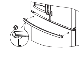
8 INSTALL THE FRESH FOOD DOOR HANDLES
Handle Design varies based on models, however Installation is same.
Stainless steel and plastic handles:
 Place the handle on the mounting fasteners, then tighten the set screws with the 1/8” Allen wrench.
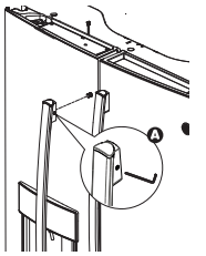
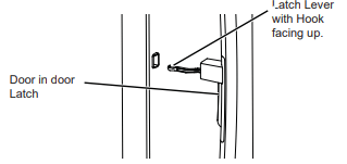
9 FOR DOOR IN DOOR MODELS ONLY
To Install the Handle:
- Align the lever with the opening on the outer door. Make sure the hook is pointed up.
- Insert the latch lever into the opening and align the handle with the mounting fasteners.
- Once the handle is flush with the outer door, tighten the set screws with a 1/8” Allen wrench
Do not remove tape from door until handle is installed
10 INSTALL THE FREEZER DOOR HANDLE
Handle Design varies based on models, however Installation is same.
Stainless steel and plastic handles:
Place the handle on the mounting fasteners, then tighten the set screws with the 1/8” Allen wrench.
Remove the handles using the same procedure as installing.
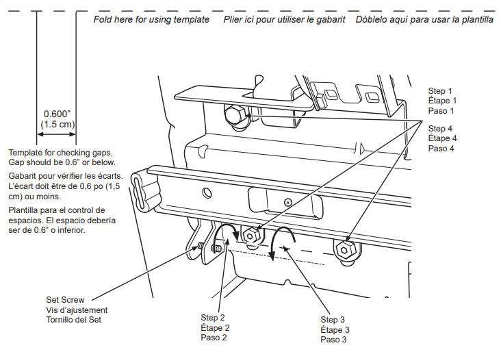
Instructions for adjusting freezer door gaps:
IMPORTANT
The 6 mounting screws (3 on each side) are NOT interchangeable with the center or top hinge screws. Drawer screws have flat washer heads, and other screws have lines/ribs on washer heads.
After installation of the freezer door, check for uniform gaps (top and bottom of right and left hand side) with the
template provided.
In the event of excessive gaps use the following steps to adjust the freezer door.
Step 1 - Loosen the 3 screws on each side (right and left) of the freezer door.
Step 2 - Adjust set screw clockwise if gap at the top is too big (see template). Turn the set screw using 3/32" hex key clockwise by quarter to half a rotation
Step 3 - Adjust set screw counter-clockwise if gap at the bottom is too big (see template). Tum the set screw using 3/32” hex key counter-clockwise by quarter to half a rotation
Step 4 - Tighten the 3 screws on each side (right and left).
Step 5 - Re-check the gaps using the template and repeat steps 1 to 4 if required and complete with step 5.
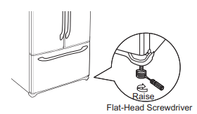
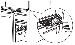
11 LEVEL THE FREEZER DOOR
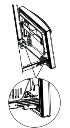
A) Locate the height adjuster cam in the freezer door. Slightly loosen the three door attachment screws on both sides using a 3/8” hex socket driver.
B) Locate and loosen the cam screw using the T-27 screw driver
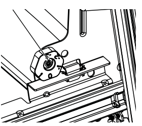
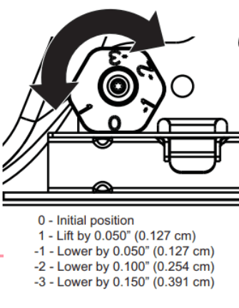
C) Lift the door on the side requiring adjustment, rotate the cam to required position.
D) After adjustment tighten the 3 attachment screws using to 65 in-lb (7.34 N-m).
12 REMOVE PACKAGING
Remove all tape, foam and protective packing from shelves and drawers.
Anti-Tip Floor Bracket Installation (Models PYE, GYE, GYS, GWE, DYE, PYD, PWE, and ZWE only)
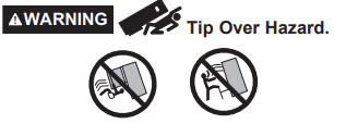
Built-in style models (model PYE, GYE, GYS, GWE, PYD, PWE, and ZWE) are top heavy, especially with any doors open. These models must be secured with the anti-tip floor bracket to prevent tipping forward, which could result in death or serious injury. Read and follow the entire installation instructions for installing the anti tip floor bracket packed with your refrigerator.
NOTE:
If you did not receive an anti-tip bracket with your purchase, call 1.800.626.8774 to receive one at no
cost. (In Canada, call 1.800.561.3344.)
For installation instructions of the bracket, visit: GEAppliances.com. (in Canada, GEAppliances.ca.)
AT-1 MEASURE CABINET OPENING AVAILABLE VS. REFRIGERATOR WIDTH
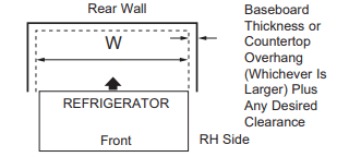
Measure width of cabinet opening where refrigerator will be placed, W.
Be sure to account for any countertop overhang, baseboard thickness and any clearance desired. Width, W, should not be less than 36''''. The refrigerator will be placed approximately in the middle of this opening.
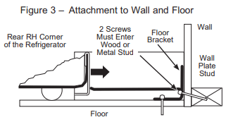
AT-2 LOCATING THE ANTI-TIP FLOOR BRACKET
A) Place the anti-tip floor bracket locator template (included inside the anti-tip kit) onto the floor up against the rear wall, within W, and in line with the desired location of the RH side of the refrigerator (see Figure 1).
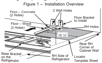
B) Place the anti-tip floor bracket onto the locator template with its RH floor holes lined up with the floor holes indicated on the template sheet, approximately 15 %4" (38.73 cm) from the edge of the sheet or the RH side of the refrigerator.
C) Hold down in position and use the anti-tip floor bracket as a template for marking the holes based upon your configuration and type of construction as shown in Step 3. Mark the hole locations with a pencil, nail or awl.
NOTE:
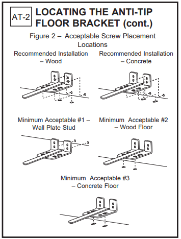
- It is REQUIRED to use at least 2 screws to mount the floor bracket (one on each side of the anti-tip floor bracket). Both must be into either the wall or the floor. Figure 2 indicates all the acceptable mounting configurations for screws. Identify the screw holes on the anti-tip floor bracket for your configuration.
AT-3 ANTI-TIP BRACKET INSTALLATION
A) WOOD Wall and Floor Construction:
- Drill the appropriate number of 4/8” (3 mm) pilot holes in the center of each floor bracket hole being used (a nail or aw! may be used if a drill is not available) AND remove the locator template from the floor.
- Mount the anti-tip floor bracket by fastening the 2, or recommended 4, #10-16 hex-head screws tightly into place as illustrated in Figure 3.
�
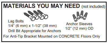
B) CONCRETE Wall and Floor Construction:
- Anchors required (not provided): 4 each 1/4” (6 mm) x 1-1/2" (38 mm) lag bolts 4 each 1/2" (12 mm) O.D. sleeve anchors
- Drill the recommended size holes for the anchors into the concrete at the center of the holes marked in Step 2.
- Install the sleeve anchors into the drilled holes. Place the anti-tip floor bracket as indicated in Step 2. Remove the locator template from the floor.
- Install the lag bolts through the anti-tip floor bracket and tighten appropriately.
C) WOOD Wall and TILE Floor Construction:
- For this special case, locate the 2 wall holes identified in Fig. 2. Drill an angled 1/8" (3 mm) pilot hole (approx. as shown in Fig. 3) in the center of each hole.
- Mount the anti-tip floor bracket using the Minimum Acceptable Installation #1, as illustrated in Fig.2.
AT-4 POSITIONING THE REFRIGERATOR TO ENGAGE THE ANTI-TIP FLOOR AND BASE BRACKETS
A) Before pushing the refrigerator into the opening, plug the power cord into the receptacle and connect waterline (if equipped). Check for leaks.
B) Locate the refrigerator’s RH side and move back approximately in line with the RH side of the cabinet opening, W. This should position the anti-tip floor bracket to engage the anti-tip base bracket on the refrigerator.
C) Gently roll the refrigerator back into the cabinet opening until it comes to a complete stop. Check to see if the refrigerator front lines up with the cabinet front face. If not, carefully rock the refrigerator forward and backward until engagement occurs and you notice that the refrigerator is fully pushed up against the rear wall.
D) If Applicable: Adjust the rear (and front) wheel height settings to fully engage the rear anti-tip brackets, while also aligning the refrigerator front with the cabinet front face.
NOTE:
If you pull the refrigerator out and away from the wall for any reason, make sure the anti-tip floor bracket is engaged when the refrigerator is pushed back against the rear wall.
13 CONNECTING THE REFRIGERATOR TO THE HOUSE WATER LINE
A cold water supply is required for automatic ice maker operation. If there is not a cold water supply, you will need to provide one. See Installing the Water Line section.
NOTES:
- Before making the connection to the refrigerator, be sure the refrigerator power cord is not plugged into the wall outlet.
- If your refrigerator does not have a water filter, we recommend installing one if your water supply has sand or particles that could clog the screen of the refrigerator's water valve. Install it in the water line near the refrigerator. If using SmartConnect™ Refrigerator Tubing Kit, you will need an additional tube (WX08X10002) to connect the filter. Do not cut plastic tube to install filter.
- Before connecting the water line to the house, purge the house line for at least 2 minutes.
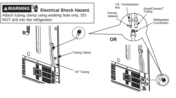
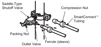
A) If you are using copper tubing, place a compression nut and ferrule (sleeve) onto the end of the tubing coming from the house cold water supply.
If you are using the SmartConnect™ tubing, the nuts are already assenbled to the tubing
B) If you are using copper tubing, insert the end of the tubing into the refrigerator connection, at the back of the refrigerator, as far as possible. While holding the tubing, tighten the fitting.
If you are using SmartConnect™ tubing, insert the molded end of the tubing into the refrigerator connection, at the back of the refrigerator, and tighten the compression nut until it is hand tight. Then tighten one additional turn with a wrench. Over tightening may cause leaks.
C) Fasten the tubing into the clamp provided to hold it in position. You may need to pry open the clamp.
�
WARNING
Connect to potable water supply only. A cold water supply is required for automatic icemaker operation. The water pressure must be between 40 and 120 psi (275-827 kilopascals)
�
�
14 TURN ON THE WATER SUPPLY
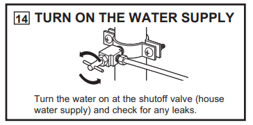
Turn the water on at the shutoff valve (house water supply) and check for any leaks)
15 PLUG IN THE REFRIGERATOR
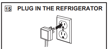
See the grounding information attached to the power cord.
Once the unit is on, press the dispenser paddle and dispense water for at least 5 minutes to remove air from the water line, and flush the filter. The first few batches of ice should also be discarded. For Non-Dispense models, throw away the first bin of ice production.
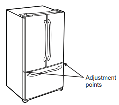
16 LEVEL THE REFRIGERATOR
The leveling legs have 2 purposes:
- Leveling legs adjust so the refrigerator is firmly positioned on the floor and does not wobble
- Leveling legs serve as a stabilizing brake to hold the refrigerator securely in position during operation and cleaning. The leveling legs also prevent the refrigerator from tipping
A) Turn the leveling legs clockwise to raise the refrigerator, counterclockwise to lower it.
NOTICE: To avoid possible property damage, the leveling legs must be firmly touching the floor.
17 LEVEL THE REFRIGERATOR DOORS
Remember a level refrigerator is necessary for getting the doors perfectly even. If you need help, review the previous section on leveling the refrigerator.
A) If you open the freeze door, you can see the center hinge
B) Insert 1/4'''' Allen wrench into the staff of the center hinge
C) Adjust the height by turning clockwise or counterclockwise. When you turn counterclockwise, the door will move up. When you turn clockwise, the door will move down.
Models PFD, PYD, GFD
INSTALLING THE WATER LINE
BEFORE YOU BEGIN
Recommended copper water supply kits are WXBX2, WXBXG, or WXBX4, depending on the amount of tubing you need. Approved plastic water supply lines are SmartConnect Rettigerator Tubing |(Wx08X10006. WXOBX1001S5 and WXO8X10025).
If the water supply to the refrigerator is from a Reverse Osmosis (RO) Water Filtration System [AND the refrigerator also has a water filter, use the refrigerator's filter bypass. Using the refrigerator's water filtration carriage in conjunction with the RO water filter can result in hollow ice cubes. Some models do not come equipped with the filter bypass pg. To obtain a fee bypass pug. call 800. [GECARES. In Canada. call 600.561.5344
This waterline installation is not warranted by the refrigerator or ice maker manufacturer. Follow these instructions carefully to minimize the risk of expensive water damage.
Water hammer (water banging in the pipes) in house plumbing can cause damage to refrigerator parts and
lead to water leakage or flooding. Call a qualified plumber to correct water hammer before installing the water supply line to the refrigerator.
To prevent burns and product damage, do not hook up the water line to the hot water line.
If the refrigerator is operated before the water connection is made for the ice maker, see Controls section on page 9 to turn ice maker off
Do not install the ice maker tubing in areas where temperatures fall below freezing.
When using any electrical device (such as a power dril) during installation, be sure the device is double
Insulated or grounded in a manner to prevent the hazard of electric shock. or is batty powered.
All installations must be in accordance with local plumbing code requirements
WHAT YOU WILL NEED
- Copper or SmartConnect Refrigerator Tubing kit. 1/4” outer diameter to connect the refrigerator to the water supply. If using copper. be sure both ends of the tubing are cut square.
To determine how much tubing you need: measure the distance from the water valve on the back of the refrigerator to the water supply pipe. Be sure there is sufficient extra tubing to allow the refrigerator to move out from the wall after installation.
SmartConnect Refrigerator Tubing Kits are available in the following lengths:
8 (2.4 m) — WxX08X10006
15’ (4.6m) —WX08X10015
25° (7.6m) —WX08X10025
WARNING
Connect to potable water supply only.
A cold water supply is required for automatic icemaker operation. The water pressure must be between 40 and 120 psi (275-827 kilopascals)
NOTE: The only GE Appliances approved plastic tubing is that supplied in SmartConnect
Refrigerator Tubing kits. Do not use any other plastic water supply line because the line is under pressure at allies. Certain types of plastic will crack or rupture with age and cause water damage to your home.
A.GE Appliances water supply kit (containing tubing. shutoff valve ad fittings sted below) is vallable at extra cost from your dealer or from Pats and Accessories. 877-959-8688 (in Canada +1800 661.1616).
A cold water supply. The water pressure must be between 20 and 120 psi (1-4-8.1 bar)
Power drill
1/2''' adjustable wrench.
Straight and Philips blade screwdriver.
Two 1/4'' outer diameter compression nuts and 2 ferrules (sleeves) - to conncet the cooper tubing to the shutoff valve and the refrigerator water valve
OR
If you are using a SmartConnect™ Refrigerator Tubing kit, the necessary fittings are preassembled to the tubing.

If your existing copper water line has a flared fitting at the end, you will need an adapter (available at plumbing supply stores) to connect the water line to the refrigerator OR you can cut off the flared fitting with a tube cutter and then use a compression fitting. Do not form end from SmartConnect™ Refrigerator Tubing.
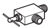
Shutoff valve to connect to the cold water line. The shutoff valve should have a water inlet with a minimum inside diameter of 5/32'' at the point of connection to the COLD WATER LINE. Saddle-type shutoff valves are included in many water supply kits. Before purchasing, make sure a saddle-type valve complies with your local plumbing codes.
Install the shutoff valve on the nearest frequently used drinking water line.
1 SHUT OFF THE MAIN WATER SUPPLY
Turn on the nearest faucet long enough to clear the line of water
2 CHOOSE THE VALVE LOCATION
Choose a location for the valve that is easily accessible. It is best to connect into the side of a vertical water pipe. When it is necessary to connect into a horizontal water pipe. make the connection to the top or side. rather than at the bottom. to avoid drawing off any sediment from the water pipe.
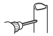
3 DRILL THE HOLE FOR THE VALVE
Drill a 1/4” hole in the water pipe (even if using a self-piercing valve). using a sharp bit. Remove any burrs resulting from drilling the hole in the pipe.
Take care not to allow water to drain into the drill.
Failure to drill a 1/4” hole may result in reduced ice production or smaller cubes.
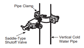
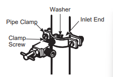
4 FASTEN THE SHUTOFF VALVE
Fasten the shutoff valve to the cold water pipe with the pipe clamp.
NOTE: Commonwealth of Massachusetts Plumbing Codes 248CMR shall be adhered to. Saddle valves are illegal and use is not permitted in Massachusetts. Consult with your licensed plumber.
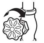
5 TIGHTEN THE PIPE CLAMP
Tighten the clamp screws until the sealing washer begins to swell.
NOTE: Do no over tighten or you may crush the tubing.
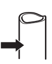
6 ROUTE THE TUBING
Route the tubing between the cold water line and the refrigerator.
Route the tubing through a hole drilled in the wall or floor (behind the refrigerator or adjacent base cabinet) as close to the wall as possible.
7 CONNECT THE TUBING TO THE VALVE
Place the compression nut and ferrule (sleeve) for copper tubing onto the end of the tubing and connect it to the shutoff valve.
Make sure the tubing is fully inserted into the valve. Tighten the compression nut securely.
For plastic tubing from a SmartConnect Refrigerator Tubing kit. insert the molded end of the tubing into the shutoff valve and tighten compression nut until it is hand tight. then tighten one additional turn with a wrench. Over tightening may cause leaks.
NOTE: Commonwealth of Massachusetts Plumbing Codes 248CMR shall be adhered to. Saddle valves are illegal and use is not permitted in Massachusetts. Consult with your licensed plumber.
8 FLUSH OUT THE TUBING
Turn the main water supply on and flush out the tubing until the water is clear.
Shut the water off at the water valve after about one quart (1 liter), or 2 minutes, of water has been flushed through the tubing
To complete the installation of the refrigerator, go back to Step 13 in the Refrigerator
Troubleshooting Tips
Normal Operating Conditions.
Newer refrigerators sound different from older refrigerators.
Modern refrigerators have more features and use newer technology.
Do you hear what I hear? These conditions are normal.
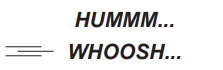
The new high efficiency compressor may run faster and longer than your old refrigerator and you may hear a high-pitched hum or pulsating sound while it is operating.
You may hear a whooshing sound when the doors close. This is due to pressure equalizing within the refrigerator
After dispensing ice, a motor will close the ice chute to keep warn room air from entering the ice bucket, maintaining ice at a freezeing temperature. The hum of the motor closing the ice chute is normal, shortly after dispensing ice.
CLICKS. POPS.
CRACKS and SNAPS
You may hear cracking or popping sounds when the refrigerator is first plugged in. This happens as the refrigerator cools to the correct temperature.
The compressor may cause a clicking or chirping sound when attempting to restart (this could take up to 5 minutes)
Expansion and contraction of cooling coils during and after defrost can cause a cracking or popping sound
On models with an ice maker, after an ice making cycle, you may hear the ice cubes dropping into the ice bucket.
After dispensing ice, a motor will close the ice chute to keep warm room air from entering the ice bucket, maintaining ice at a freezing temperature.
START UP COOLING
It can take up to 24 hours for the refrigerator and freezer temperatures to match the display. During time refrigerator and freezer door openings should minimized.
TIPS
Freezer cools first
Refrigerator compartment cools last; it may take several hours after the freeze
Turning off ice maker makes both refrigerator and freezer food cool faster.

You may hear the fans spinning at high speeds. This happens when the refrigerator is first plugged in, when the doors are opened frequently or when a large amount of food is added to the refrigerator or the freezer compartments. The fans are helping to maintain the correct temperatures
The fans change speeds in order to provide optimal cooling and energy savings.

The flow of refrigerant through the cooling coils may make a gurgling noise like boiling water
Water dropping on the defrost heater can cause a sizzling, popping or buzzing sound during the defrost cycle
A water dripping noise may occur during the defrost cycle as ice melts from the evaporator and flows into the drain pan.
Closing the door may cause a gurgling sound due to pressure equalization
Before you call for service
Save time and money! Review the charts on the following pages first and you may not need to call for service.
Water filter indicated as installed incorrectly or a leak is present on cap control panel
- Water filter installed backward or is leaking.
- Check for leak. If no leak is present. remove filter/bypass plug’. rotate 180° and reinstall
“Warning Triangle” is it
Replace Filter/Replace Water Filter slit
Over Due light is lit
- Water filter leaking or needs replacing
- Water filter backwards
- Replace water filter. check for leak
- Remove filter. rotate 180° and reinstall
Dispenser Off is lit
- Control A. B & C
- Wrong filter installed
- Replace filter with proper filter
- Remove filter. rotate 180° and reinstall
Not filtering
- Filter bypass installed Controls B & C
- Install correct water filter
Reset Filter is lit
- Water filter leaking or needs replacing
- Replace water fiter. or install fiter bypass **
- Press and hold Reset Filter for 3 seconds to reset (Control D only)
Water filter indicator light is not lit
- This is normal. This indicator will tum on to tell you that you need to replace the filter soon.
- See About the Water Filter for more information.
Handle is loose/handle has a gap.
- Handle needs adjusting
- See Attach Refrigerator Handle and Attach the Freezer Handle sections for detailed instructions.
Refrigerator beeping
- This is door alarm
- Turn off or disable with door closed
- If door open and alarm is sounding. you can only snooze the alarm
Not cooling
- The cooling system is off
Water has poor taste/odor
- Water dispenser has not been used for a long time
- Dispense water. until all water system is replenished
Walter in glass is warm
- Normal when refrigerator is first installed
- Wait 24 hours for the refrigerator to completely cool down.
- Waler dispenser has not been used for a long time
- Dispense water. until all water in system is replenished
- Water system has drained
- Allow several hours for replenished supply to chil
Waler dispenser does not work
- Walter supply line turned off or not connected
- See Installing the Water Line
- Waier filter clogged or fiter/bypass plug not installed
- Replace filler cartridge or remove filter and install bypass plug **
- Air may be trapped in the water system
- Press the dispenser arm for at least 5 minutes.
- Waler in reservoir is frozen because the controls are set too cold.
- Set the refrigerator control to a warmer setting and wait 24 hours. if the water does not dispense after 24 hours. call for service
Water spurting from dispenser*
- Newly installed filter cartridge
- Run water from the dispenser for 5 minutes (about 2 gallons)
No water or ice cube production*
- Supply line or shutoff valve is clogged
- Water filter is clogged
- Replace filter cartridge or remove filter and install bypass plug"
- Filter cartridge not properly installed
- Remove and reinstall filter cartridge. being certain that it locks in place.
- Ice maker is turned off
- Check that the ice maker Is turned on. See About the Automatic Ice Maker.
Waler is leaking from dispenser*
- Air may be present in the waterline system. causing water to drip after being dispensed
- Dispense water for at least § minutes to remove air from system
AUTO FILL under fill/no fill*
- Not all containers work with AUTOFILL
- Error message
- See page 14
- Clean sensor. See page 14.
AUTO FILL overfills
- Not all containers work with AUTO FILL
Freezer cooling. refrigerator not cooling
- Normal, when refrigerator first plugged in or after extended power outage
- Wait 24 hours for temperature in bath compartments to reach selected temperatures.
Ice dispenser opens after closing freezer drawer*
- Normal
- The ice dispenser door may open after closing freezer door to allow access
Low brewing flow rate
- There may have been a dent at the bottom of K-Cup causing the pin to pierce the filter allowing coffee grounds clogging the bottom pin
- Avoid using damaged rented K-cups. and clean the lower needle before next brew
Low brewing flow rate/water drips from inner door
- Top needle of the brewer clogged
- Unclog the top needle holes using a paper clip and rinse brewer. Rinse brewer after every use.
Brewer Is not detected or hot water leaking from top of the brewer
- Incorrect assembly of brewer in the bracket
- Make sure the Keurig Lago is in the front. Push brewer all the way in the brackets
Coffee dispensed with splash or bubble bursting
- Blocked vent hole in the brewer
- Make sure the vent hole at the bottom of the brewer is clear from food or any other contamination
Beverage quality not as expected
- You may be using non-standard or out dated K-Cups
- Recommend using official Keurig K-cups that are not past expiration and. have not been damaged
Liquid drips from the brewer after brewer cycle is completed and the brewer is removed from the bracket
- It is possible for liquids to be retained by the brewer and drip when it is removed
- Use a cloth or container to capture the drips when brewer is removed
Delay when using Keurig K-cup Po dispenser
- To ensure a quality beverage Is. delivered, a short delay is required to ensure the refrigerator is operating correctly
- Ensuring consistent. quality operation requires the refrigerator to delay dispense for a short period of time
After brewing. my powdered beverage is not fully cleared from the used pod
- Depending on size selected. the powder may not dissolve fully
- Some powdered beverages develop into clumps’ when left sitting for some time
- Shake the powdered pods before brewing to break up these clumps and allow better clearing. For powdered beverage with no filter. use the Cocoa cycle selection
Brewer lid is difficult to close
- K-cup is not fully seated
- Press K-cup all the way down into the brewer prior to closing the lid. Lower needle must puncture K-cup before closing the brewer lid
Brewer leaks during the brew cycle
- Trouble in closing brewer lid or damaged K-cup
- Press K-cup all the way down into the brewer prior to closing the lid. Lower needle must puncture K-cup before closing the brewer lid. Recommend using official Keurig K-cups that have not been damaged and have a good seal between the top cover and plastic bottom
My refrigerator door squeaks
- Diminished lubricant because of accidental cleaning of the lubricant on the hinge
- It is best to order GEA lubricant service part number WR97X166 and apply it on the hinge at specified location. It is possible to spray some non-toxic lubricants such as silicone based nonstick cooking spray. petroleum jelly or NSF approved food grade lubricants. IMPORTANT: Do not use WD-40 as it will remove any remaining grease in or around the hinge.
- Improper leveling
- Make sure the unit is leveled
- If doors were removed and reassembled during installation process. waterline and/harness under Top Hinge cover may get out of position and rub against door while door swivels.
- Remove the Top Hinge cover and make sure the waterline and harness that passes through the hinge pin have been properly seated and do not touch any of the door parts during rotation. Applying some food grade lubricant around door thimble area will also help.
Truth or Myth
The refrigerator water filter may require replacement prior to six months
- Answer: TRUE
- Explanation: The water filter indicator will indicate the need to replace the water filter every six months or 170 gallons of water dispensed (select models only). Water quality varies from city to city. water ow from the dispenser slows. or ice production decreases the water filter should be replaced, even though the filter indicator may not indicate the need for replacement.
The automatic ice maker ln my refrigerator will produce ice when the refrigerator is plugged
Into a power receptacle
- Answer: MYTH
- Explanation: The refrigerator must be connected to water and the ice maker must be turned on. Make sure the lce maker is turned on only after the waterline I connected and water is turned on. The ice maker can be turned on/off from the control panel. See About the Automatic Ice Maker.
After the refigerator has been plugged in and connected to water. | will immediately have unlimited chilled water available from the water dispenser
- Answer: MYTH
- Explanation: The water dispenser tank located inside the refrigerator stores water for dispensing. The water in this tank requires 24 hours to chill after installation. High usage conditions will not allow time for the water to chill.
After water dispenses, a few drops of water are normal.
- Answer: TRUE
- Explanation: A few drops of water may fall from the dispenser. after the dispenser paddle has been released. To minimize the drops. remove the glass slowly from the dispenser.
I will never see frost inside the freezer compartment
- Answer: MYTH
- Explanation: Frost inside the freezer typically indicates that the door is not properly sealed. or has been left open. If frost is found. clear the frost using a plastic spatula and towel. then check to ensure that no food packages or containers are preventing the freezer door from. closing. Check the refrigerator control panel to ensure the door alarm is on.
When the refrigerator is installed. or after replacing the water filter. I must dispense water for five minutes.
- Answer: TRUE
- Explanation: A newly installed refrigerator or water filter contains air in the water lines. Press the dispenser paddle and dispense cold water for at least 5 minutes to remove air from the water line, and flush the filter. For Non Dispense models, throw away the first bin of ice production after filter replacement.
To fill the ice bucket to the maximum capacity. | should dispense 12 and 18 hours after installation.
- Answer: TRUE
- Explanation: Dispensing 3-4 cubes 12 hours and 18 hours after installation. allows ice to disperse within the ice bucket. which in turn calls on the ice maker to produce additional ice. Normal ice production = 100 cubes in 24 hours.
I can use the water filter bypass plug to determine if the filter requires replacement.
- Answer: TRUE
- Explanation: Decrease in flow from the water dispenser. or decreased ice production. may indicate the need to replace the water filter. Install the water filter bypass plug (provided with the refrigerator on some. models"). and check flow from the dispenser. If water flow returns to normal with the bypass plug in place. replace the water filter.
The top of the refrigerator doors will always be aligned
- Answer: MYTH
- Explanation: Several things can affect the refrigerator door alignment. including the floor the refrigerator is installed on and loading of doors. If the top of the refrigerator doors is not aligned. use a 1/4” Allen wrench to adjust the right/left hand door. The adjustment screw is located on the bottom right or left hand side of the door; open the freezer door to access the screw.
Refrigerator door handles can be easily tightened.
- Answer: TRUE
- Explanation: If door handles are loose or have a gap. the handle can be adjusted using a 1/8” allen wrench. on set screws located on the ends of the handles.
There may be odor and taste problems with your ice
- Answer: TRUE
- Explanation: After starting the ice maker. or replacing the water filter. throw away the first bin of ice production to avoid odor and taste problems.
I can make fine adjustments to the refrigerator doors to align them.
- Answer: TRUE
- Explanation: If the refrigerator doors are not aligned. use a 1/4” Allen wrench to adjust the right hand door. The adjustment screw is located on the bottom of the right/left hand door. Open the freezer door to access.
Door removal is always required for installation
- Answer: MYTH
- Explanation: Check chart on reverse side of this instruction. Doors should only be removed when necessary to prevent damage from passage way or access to final location.
Refrigerator doors that won’t close after installation can be adjusted to close properly
- Answer: TRUE on some models
- Explanation: On some models doors have to be removed at 90° and installed at 90° to cabinet as described in procedure for Reinstalling the Refrigerator Doors in order for door to close properly.
There is an adjustment to rear wheels.
- Answer: MYTH
- Explanation: Front leveling legs are adjustable and should be used to balance the refrigerator. Leveling legs are used to make initial refrigerator door adjustments.
Check for leaks after all water connections are made
- Answer: TRUE
- Explanation: While purging the air from the water system. check all water line connections for leaks. Check the connection to the household water supply at back of refrigerator. and door water line connects.
Any packaging residue can be cleaned off the refrigerator using any cleaner.
- Answer: MYTH
- Explanation: Do not use wax. polish. bleach. or other products containing chlorine on Stainless Steel panels. door handles and trim. Check this instruction under “Cleaning the Outside” for full detail:
�
�
�
�
�
�
�