Loading ...
Loading ...
Loading ...
25
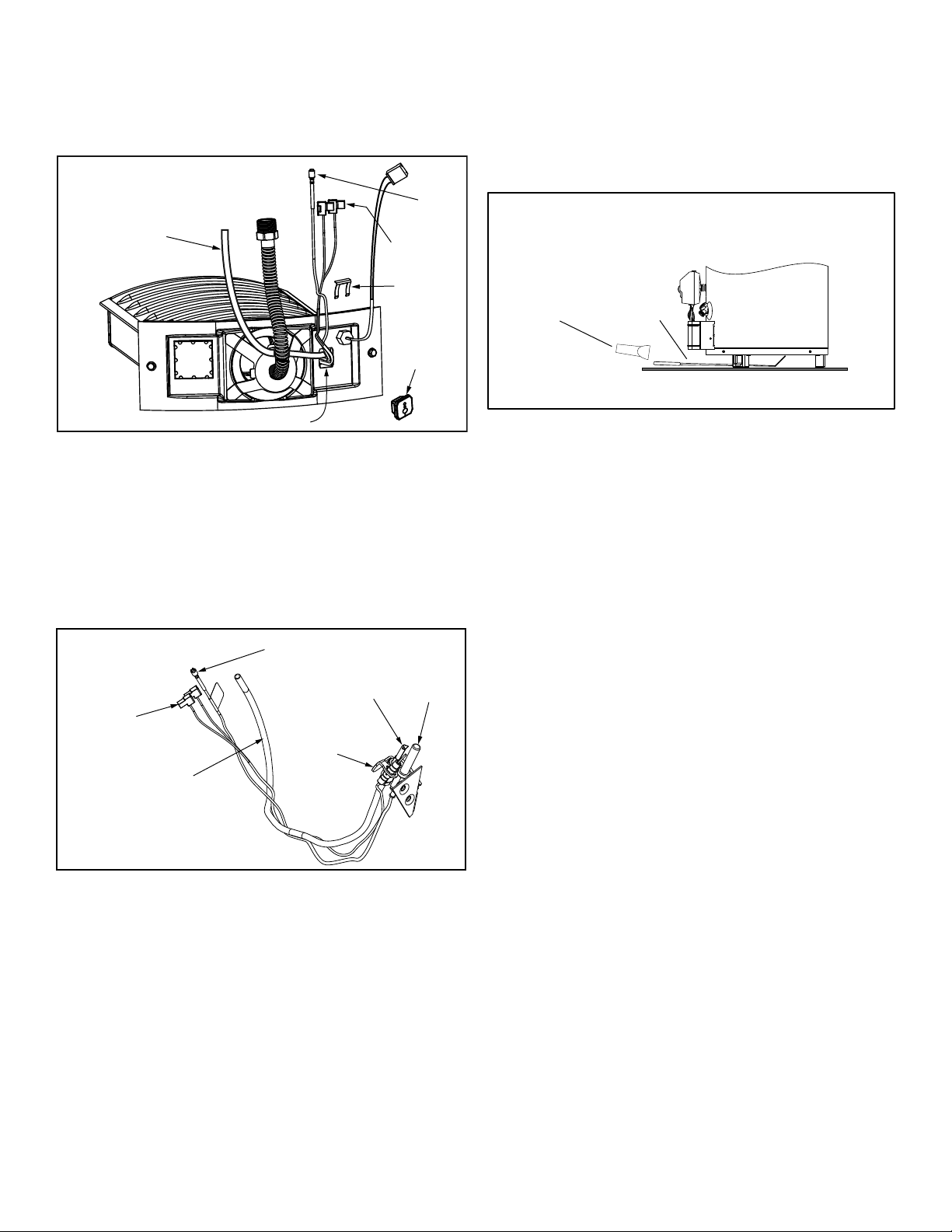
Replacing the Pilot/Thermopile Assembly
1. Remove the burner assembly as directed previously.
2.
Lift the retainer clip straight up from the back of
the manifold component block (using a flat-blade
screwdriver), then remove the manifold component
block from the burner door assembly
(Figure 25).
3. Locate and remove the phillips screw attaching the pilot to
the pilot bracket,
then pull the pilot/thermopile assembly
(including the igniter wire) out of the burner door assembly.
4. Using a 7/16” wrench, loosen the nut securing the pilot
tube to the pilot assembly (right-hand threads).
5. Pull the pilot tube from the pilot assembly (Figure 26).
IMPORTANT: Be careful not to bend or alter the position of
the pilot assembly components.
6.
Using the old pilot tube as a guide, bend the new pilot
tube to match the old one. Make only the bends closest
to the pilot before going to the next step.
7. Reconnect the pilot tube and tighten the nut securing it
to the pilot assembly. To prevent any bending of the pilot
bracket, use pliers to hold the pilot assembly bracket
while tightening the pilot nut.
IMPORTANT: Keep the pilot orifice in the pilot when
making the connection. DO NOT operate the water heater
without the pilot orifice installed.
8. Push the new pilot assembly connectors through the
opening in the burner door (See Figure 25).
9. Attach the pilot assembly to the Burner Door Assembly.
10.
Position the new thermopile wires through the top opening
of the manifold component block (Figure 25). Be sure that
the igniter wire is positioned through the middle opening
of the manifold component block. Position the pilot tube
through the bottom opening of the manifold component
block.
11. See “Replacing the Burner Door Assembly” on page 26.
Figure 25
Manifold Component
Block Assembly
Thermopile
Connectors
Manifold
Component
Block
Pilot Tube
Igniter
Wire
Burner Door Opening
Retainer
Clip
Figure 26
Pilot/Thermopile Assembly
Pilot/Thermopile
Assembly
Igniter Connector
Pilot
Thermopile
Thermopile
Connectors
Pilot Tube
(Ferrule Nut
Not Shown)
External Inspection & Cleaning of the
Flame-trap
Although not likely to occur, if debris collects on the flame-
trap, use a vacuum, compressed air, or a soft bristle brush
to remove it.
NOTE: If unable to inspect or clean the flame trap from
underneath, follow the “Cleaning the Combustion Chamber
and Flame-trap” section instructions.
Figure 27
Flame-trap visual inspection
Mirror
Flashlight
Cleaning the Combustion Chamber and
Flame-trap
1. Follow procedure outlined in “Removing the Burner
Door Assembly”.
2. Use a vacuum cleaner/shop vac to remove all loose
debris in the combustion chamber (Figure 28). Use
compressed air to clear any dust or debris that may
have accumulated in the flame-trap.
3. Reassemble following the procedure under “Replacing
the Burner Door Assembly”.
Loading ...
Loading ...
Loading ...