Loading ...
Loading ...
Loading ...
15
should be vertical past any mixing valve or supply line
to the air handler to remove air bubbles from the sys-
tem. Otherwise, these bubbles will be trapped in the air
handler heat exchanger coil, reducing the efficiency.
• Do not connect the water heater to any system or
components previously used with non-potable water
heating appliances when used to supply potable water.
NOTE: Water heaters covered by this manual are suitable
for combination water (potable) heating and space heating,
but not suitable for space heating applications only.
Some jurisdictions may require a backflow preventer
in the incoming cold water line. This may cause the
temperature and pressure relief valve on the water heater
to discharge or weep due to expansion of the heated water.
A diaphragm-type expansion tank suitable for potable
water will normally eliminate this weeping condition. Please
read and follow the manufacturer’s instructions for the
installation of such tanks.
Also see “Water System Piping” section for additional
instructions on the proper installation and operation of this
water heater.
Solar Installation
If this water heater is used as a solar storage heater
or as a backup for the solar system, the water supply
temperatures to the water heater tank may be in excess of
120°F. A mixing valve or other temperature limiting valve
must be installed in the water supply line to limit the supply
temperature to 120°F. Also, install mixing valves at each
point of use. The unit must be set to Standard Mode (See
Operating the Temperature Control System section).
NOTE: Solar water heating systems can often supply water
with temperatures exceeding 180°F and may result in water
heater malfunction.
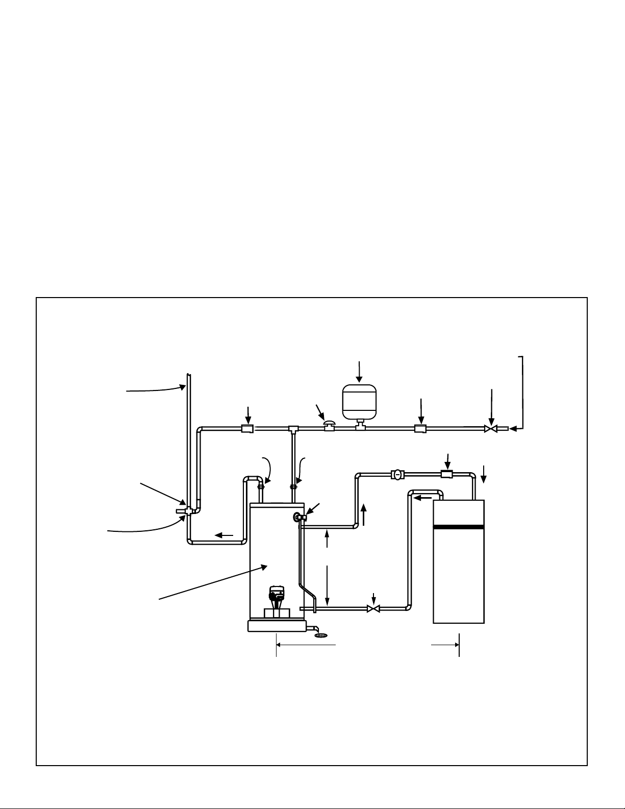
IN
REMOVE A
MUST BE VERTICAL TO
IR BUBBLES
E
OUT
COIL
AIR
HANDLER
TO
AIR
HANDLER
SHUT-OFF
VALVE
*
EXPANSION TANK
VACUUM
RELIEF
VALVE
COLD WATER INLET
VA
FLOW CONTROL
LV
PUMP
SHUT-OFF
CHECK VALVE
†
(1/8” HOLE
DRILLED IN CLAPPER)
VALVE
CHECK
VALVE
†
TEMP/
PRESSURE
RELIEF
VALVE
TEMPERED WATER
TO FIXTURES
(MUST MEET TEMPS LISTED
IN MASS. CODE 248 CMR
†
)
MIXING VALVE
(MUST BE INSTALLED BELOW
TOP OF WATER HEATER
AS PER MANUFACTURER’S
RECOMMENDATIONS)
UNION
UNION
HOT
WATER
OUT
*
MASSACHUSETTS INSTALLATION REQUIREMENTS:
1.) CONNECT ELECTRONICALLY-CONTROLLED TIMER TO AN ALL-BRONZE PUMP. PUMP MUST ACTIVATE EVERY 6 HOURS
FOR 60 SECONDS. TURN PUMP TIMER OFF BEFORE CLOSING PIPING LOOP SHUT-OFF VALVE.
2.) ALL WATER PIPING MUST BE INSTALLED AND INSULATED IN ACCORDANCE WITH MASSACHUSETTS CODE (248 CMR
& 780 CMR).
3.) PIPING LOOP BETWEEN WATER HEATER AND AIR HANDLER MUST BE INSTALLED IN COMPLIANCE WITH 248 CMR.
† REQUIRED FOR MASSACHUSETTS.
‡ PIPING FROM THE TOP OF THE WATER HEATER WITH TEES IS ACCEPTABLE.
WATER HEATER ACCEPTED
BY THE BOARD FOR
INSTALLATION IN
MASSACHUSETTS.
†
SEE
NOTE ‡
100’-0” MAXIMUM DISTANCE
FROM WATER HEATER
TO FAN COIL AND BACK
(DEVELOPED LENGTH) NOT
INCLUDING COIL IN HEATING UNIT.
†
Figure 16
Typical Mixing Valve Installation
Combination Space Heating/Potable
Water Heating System
Loading ...
Loading ...
Loading ...