Loading ...
Loading ...
3
Fig. 1
wok Ø 20-32
fast Ø 20-26
semifast Ø 14-20
auxiliary Ø 10-14
INSTRUCTIONS FOR USE
FOR VITROCERAMIC HOBS SEE ADDITIONAL INSTRUCTIONS
Installation
All the operations concerned with the installation (electrical connection) must be
carried out by qualified technicians, in terms with the standards in force.
For specific instructions, kindly read the part reserved for the installation technician.
Use
Gas burners (Fig. 1-1a-1b).
The ignition of the gas burner is carried out by putting a small flame to the upper part
holes of the burner, pressing and rotating the corresponding knob in an anti-clockwise
manner, until the maximum position has coincided with the marker. When the gas
burner has been turned on, adjust the flame according to need. The minimum position
is found at the end of the anti-clockwise rotation direction.
In models with automatic ignition, operate the knob as described above, pressing
simultaneously, the corresponding push-button. The electric spark between the
ignition plug and the burner provides the ignition of the burner itself. After ignition,
immediately release the push-button and adjust the flame according to need.
To start the burner in models equipped with a thermoelectric resistance keep the knob
pressed hard for 10 seconds, as described above, after placing it on its maximum value.
After releasing the knob, make sure the burner is actually lit.
N.B. - we recommend the use of pots and pans with a diameter matching that of the
burner, thus preventing the flame from escaping from the bottom part and
surrounding the pot
- do not leave any empty pots or pans on the fire
- do not use any tools for grill-cooking on Crystal hobs.
When cooking is finished, it is also a good norm to close the main gas pipe tap and
cylinder.
GAS
10
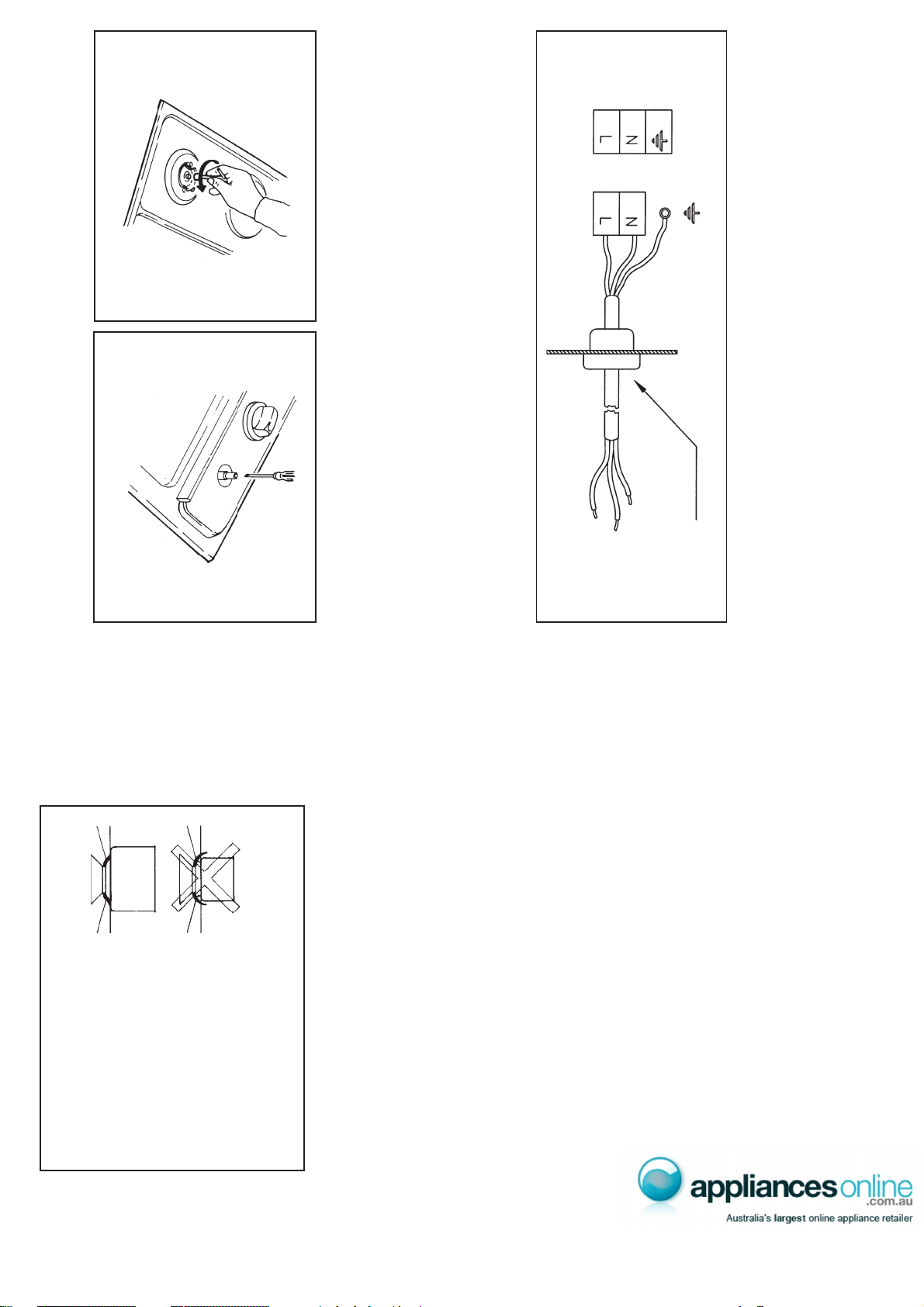
Fig. 7
be required, it will be necessary to interpose an omnipolar switch with minimum
aperture between the 3 mm. contacts, dimensioned to bear the plate load and it must
follow the standards in force (the yellow/green earth cable must not be interrupted by
the switch). The plug or omnipolar switch must be easily reached on the installed
equipment.
The manufacturers decline any responsibility in the event of non-compliance with
what is described above and the accident prevention norms not being respected and
followed.
Adaptation to various types of gas
(Fig. 8-9) Should the appliance be pre-set for a different type of gas than that available,
proceed as follows:
• replace the injectors (Fig. 7) with the corresponding type of gas to be used (see table
"Uses characteristics").
• to adjust to the minimum, use a screwdriver on the screw placed on the tap (Fig. 8)
after turning the tap to its minimum position. For LPG (butane/propane) screw
tight.
Fig. 9
Fig. 8
CABLE-CLAMP
Loading ...
Loading ...
Loading ...