VC-Grid™ Family
User Manual

© 2012-2018 HARMAN PROFESSIONAL DENMARK ApS. All rights reserved. Features, specifications and appearance are subject
to change without notice. HARMAN PROFESSIONAL DENMARK ApS and all affiliated companies disclaim liability for any injury,
damage, direct or indirect loss, consequential or economic loss or any other loss occasioned by the use of, inability to use or reliance
on the information contained in this document. Martin is a registered trademark of HARMAN PROFESSIONAL DENMARK ApS
registered in the United States and/or other countries.
HARMAN PROFESSIONAL DENMARK ApS
, Olof Palmes Alle 44, 8200 Aarhus N, Denmark
HARMAN PROFESSIONAL SOLUTIONS U.S.
, 8500 Balboa Blvd., Northridge, CA 91329, USA
www.martin.com
P/N 35000263, Rev. F

Contents
Safety Information. . . . . . . . . . . . . . . . . . . . . . . . . . . . . . . . . . . . . . . . . . . . . . . . . . . . . . . . . . . . . . . . . . 4
Introduction . . . . . . . . . . . . . . . . . . . . . . . . . . . . . . . . . . . . . . . . . . . . . . . . . . . . . . . . . . . . . . . . . . . . . . . . 7
Unpacking . . . . . . . . . . . . . . . . . . . . . . . . . . . . . . . . . . . . . . . . . . . . . . . . . . . . . . . . . . . . . . . . . . . . . . . . 7
Precautions to avoid damage . . . . . . . . . . . . . . . . . . . . . . . . . . . . . . . . . . . . . . . . . . . . . . . . . . . . . . . . . 7
VC-Grid overview . . . . . . . . . . . . . . . . . . . . . . . . . . . . . . . . . . . . . . . . . . . . . . . . . . . . . . . . . . . . . . . . . . 9
Physical installation . . . . . . . . . . . . . . . . . . . . . . . . . . . . . . . . . . . . . . . . . . . . . . . . . . . . . . . . . . . . . . . 10
Mounting frames . . . . . . . . . . . . . . . . . . . . . . . . . . . . . . . . . . . . . . . . . . . . . . . . . . . . . . . . . . . . . . . . . . 11
System installation . . . . . . . . . . . . . . . . . . . . . . . . . . . . . . . . . . . . . . . . . . . . . . . . . . . . . . . . . . . . . . . . 12
Installing a P3 system . . . . . . . . . . . . . . . . . . . . . . . . . . . . . . . . . . . . . . . . . . . . . . . . . . . . . . . . . . . . . . 12
Installing a DMX-controlled system . . . . . . . . . . . . . . . . . . . . . . . . . . . . . . . . . . . . . . . . . . . . . . . . . . . . 15
Connecting additional devices to a VC-Grid chain . . . . . . . . . . . . . . . . . . . . . . . . . . . . . . . . . . . . . . . . 20
System setup . . . . . . . . . . . . . . . . . . . . . . . . . . . . . . . . . . . . . . . . . . . . . . . . . . . . . . . . . . . . . . . . . . . . . 21
Setting up for P3 display . . . . . . . . . . . . . . . . . . . . . . . . . . . . . . . . . . . . . . . . . . . . . . . . . . . . . . . . . . . . 21
Setting up for DMX control. . . . . . . . . . . . . . . . . . . . . . . . . . . . . . . . . . . . . . . . . . . . . . . . . . . . . . . . . . . 21
Using the VC-Grid. . . . . . . . . . . . . . . . . . . . . . . . . . . . . . . . . . . . . . . . . . . . . . . . . . . . . . . . . . . . . . . . . 23
P3 display . . . . . . . . . . . . . . . . . . . . . . . . . . . . . . . . . . . . . . . . . . . . . . . . . . . . . . . . . . . . . . . . . . . . . . . 23
DMX control . . . . . . . . . . . . . . . . . . . . . . . . . . . . . . . . . . . . . . . . . . . . . . . . . . . . . . . . . . . . . . . . . . . . . . 23
Local control button . . . . . . . . . . . . . . . . . . . . . . . . . . . . . . . . . . . . . . . . . . . . . . . . . . . . . . . . . . . . . . . . 23
Service and maintenance. . . . . . . . . . . . . . . . . . . . . . . . . . . . . . . . . . . . . . . . . . . . . . . . . . . . . . . . . . 25
Cleaning. . . . . . . . . . . . . . . . . . . . . . . . . . . . . . . . . . . . . . . . . . . . . . . . . . . . . . . . . . . . . . . . . . . . . . . . . 25
Installing new software . . . . . . . . . . . . . . . . . . . . . . . . . . . . . . . . . . . . . . . . . . . . . . . . . . . . . . . . . . . . . 25
Troubleshooting . . . . . . . . . . . . . . . . . . . . . . . . . . . . . . . . . . . . . . . . . . . . . . . . . . . . . . . . . . . . . . . . . . 26
Specifications . . . . . . . . . . . . . . . . . . . . . . . . . . . . . . . . . . . . . . . . . . . . . . . . . . . . . . . . . . . . . . . . . . . . . 27
4 VC-Grid Safety and Installation Guide
Safety Information
The following symbols are used to identify important safety information on the product and/or in this
document:
Warning!
• Read this user manual before installing and operating the Martin® VC-Grid™ and keep this
manual for future reference.
• Follow the safety precautions given in this user manual and in the manuals of all the devices you
connect to it. Observe all warnings given in manuals and printed on devices. Make sure that
everyone who is involved in working on or using the VC-Grid has read and understood these
safety precautions and warnings.
• Install, connect, operate and service devices only as described in this manual and connected
devices’ manuals and only in accordance with local laws and regulations. All Martin manuals are
supplied with devices and are also available for download from www.martin.com.
• The VC-Grid is not for household use. It presents risks of severe injury or death due to fire and
burn hazards, electric shock and falls. It must be installed by qualified technicians only.
• The VC-Grid does not have user-serviceable parts. Refer any operation not described in this
manual to Martin or its authorized service agents.
• The VC-Grid is designed to integrate with other Martin devices in a video display installation.
VC-Grid modules are considered as components that will be installed into final equipment. It must be
reconfirmed that the final equipment still meets applicable EMC (electromagnetic compatibility) standards.
Technical Support
If you have questions about how to install or operate the VC-Grid system safely, please contact Harman
Professional Technical support:
• For technical support in North America, please contact: HProTechSupportUSA@harman.com
Phone: (844) 776-4899
• For technical support outside North America, please contact your national distributor.
PROTECTION FROM ELECTRIC SHOCK
• Read and respect the directions given in the user manuals of all the devices that you intend to connect to
the VC-Grid, particularly the instructions, warnings and limits that apply to:
- system layout,
- connections to other devices,
- specified cables,
WARNING!
Read the safety precautions in this section before
installing, powering, operating or servicing this
product.
Warning!
Safety hazard.
Risk of severe
injury or
death.
Warning!
Hazardous
voltage. Risk
of severe or
lethal electric
shock.
Warning!
Fire hazard.
Warning!
Refer to
manual before
installing,
operating or
servicing.

Safety Information 5
- maximum cable lengths, and
- maximum number of devices that can be connected.
• Use only the cables specified by Martin for the devices concerned to interconnect them. If the specified
cables are not long enough for an intended cable run, consult Martin for assistance in finding or creating a
safe alternative cable
• Do not allow the total length of the cables used in a linked chain of VC-Grid modules to exceed 50 m
(164 ft.) from the 48 VDC power source (Martin P3 PowerPort 1500™, Martin IP66 PSU 240W™ or other
external PSU) to the last VC-Grid at the end of the chain.
• Do not exceed the maximum safe limits given in the tables below. The figures allow for cable in a chain
with a total hybrid cable length of 50 m (164 ft.).
- If you supply VC-Grid modules with DC power from an output on a Martin P3 PowerPort 1500, do not
connect more than one linked chain of VC-Grids to one DC power output, and respect the limits given in
Table 1 below:
- If you supply VC-Grid modules with DC power from a Martin IP66 PSU 240W, do not connect more
than one linked chain of VC-Grids to the DC power output, and respect the limits given in Table 2 below.
Type of VC-Grid module in
chain
Maximum permitted
number of modules in one
chain
VC-Grid 16x16 15 4
VC-Grid 8x8 25 12
VC-Grid 8x8 30 12
VC-Grid 8x8 60 12
VC-Grid 4x4 60 45
Table 1: Maximum number of VC-Grid modules per P3 PowerPort 1500 output
Type of VC-Grid module in
chain
Maximum permitted
number of modules in one
chain
VC-Grid 16x16 15 4
VC-Grid 8x8 25 8
VC-Grid 8x8 30 8
VC-Grid 8x8 60 8
VC-Grid 4x4 60 30
Table 2: Maximum number of VC-Grid modules per Martin IP66 PSU 240W

6 VC-Grid Safety and Installation Guide
- If you supply a chain of VC-Grid modules with DC power from a generic 48 VDC external PSU (power
supply unit), do not connect more than one linked chain of VC-Grids to one DC power output at the
PSU, and do not exceed the maximum permitted number of modules that you can connect in one chain
as given in Table 3 below. At the same time, do not create a chain that will exceed the maximum power
rating of the PSU output used to supply that chain with power (to find the power consumption of the
chain, multiply the number of modules in the chain with the wattage of each module as given in Table 3).
Each time you reach (a) the maximum permitted number of modules in one chain, or (b) the PSU
output’s maximum power rating – whichever you reach first – you must create a new chain of modules
that is connected to a new 48 VDC power output.
• If you supply a chain of VC-Grids with DC power from a generic 48 VDC external PSU and the DC
output used does not have constant overcurrent protection that limits current to 8 A, install an inline
fuseholder with a 7.5 A or 8 A fuse on the circuit that you connect to that DC output.
• Provide a means of locking out AC mains power that allows power to the installation to be shut down and
made impossible to reapply, even accidentally, during work on the installation.
• Shut down power to the installation during service and when it is not in use.
• Before applying power to the installation, check that all power distribution equipment and cables are in
perfect condition and rated for the current requirements of all connected devices.
• Isolate the installation from power immediately if any product, power cable or power plug is in any way
damaged, defective or wet, or if it shows signs of overheating.
• Do not expose the VC-Grid to rain or moisture.
PROTECTION FROM BURNS AND FIRE
• The VC-Grid is cooled by convection. Provide free airflow and a minimum clearance of 10 mm (0.4 in.)
around modules. Monitor the VC-Grid’s temperature by calling up temperature readouts on the P3
System Controller. If any of the product temperature readouts exceed the levels given in Table 4 on page
8, provide fan assistance to give active cooling to the installation.
• Do not operate the VC-Grid if the ambient temperature (Ta) exceeds 45° C (113° F).
• Do not modify the VC-Grid in any way not described in this manual or install other than genuine Martin
parts. Use only accessories approved by Martin.
PROTECTION FROM INJURY
• When installing the VC-Grid above ground level, ensure that the installation hardware and supporting
structure can hold at least 10 times the weight of all the devices they support.
• In an overhead installation or where the VC-Grid may cause injury if it falls:
- block access below the work area and work from a stable platform whenever installing, servicing or
moving the VC-Grid, and
- as soon as work is completed, check that all hardware and components are securely in place and
fastened to supporting structures.
Type of VC-Grid module in
chain
Maximum permitted
number of modules in one
chain
Wattage per VC-Grid
module
VC-Grid 16x16 15 4 60 W
VC-Grid 8x8 25 12 30 W
VC-Grid 8x8 30 12 30 W
VC-Grid 8x8 60 12 30 W
VC-Grid 4x4 60 45 8 W
Table 3: Maximum number of VC-Grid modules per 48 VDC external PSU

Introduction 7
Introduction
Thank you for selecting a product from the Martin VC-Grid™ family. These compact LED-based display
modules are designed to integrate into a Martin P3™ video system to display video from a variety of
sources, and they can also be controlled using DMX. Use of an RDM-compliant DMX controller allows
two-way communication and remote management of VC-Grid modules from the controller.
The VC-Grid combines flexibility and simplicity with high-quality video display capabilities. Used with or
without a front diffuser, multiple VC-Grids can be combined in ways that give exceptional creative flexibility.
A hybrid power and data cabling system allows VC-Grids to be daisy-chained for easy setup and minimal
cabling.
The VC-Grid is a square array of LEDs arranged on a rigid module. It offers the following features:
• RGB color
• Various pixel pitch (center-to-center LED distance) options: 15, 25, 30 or 60 mm
• Three pixel layout options: 4x4, 8x8 or 16x16 LEDs per module
• Individually controllable pixels
• High-quality 16-bit per color image processing technology
• Pixel-level brightness and color calibration for optimal image quality
• P3 and DMX control with automatic protocol detection
• Intuitive pixel mapping and addressing using a Martin P3 system controller
• Single hybrid cable for power and data input and throughput
• External power and data processor (Martin P3 PowerPort™) and simple cabling system.
For dimensions drawings of all the products in the VC-Grid family, please see the VC-Grid Product Support
pages on the Martin website at www.martin.com
The naming convention for the VC family is as follows:
Martin user documentation is supplied with products. Please check that you have the latest version available
by checking the product’s support page on the Martin website at http://www.martin.com. Besides the latest
user documentation, the support pages also provide the latest specifications, firmware updates and support
information for Martin products.
Martin welcomes input from users. Comments or suggestions regarding this manual can be e-mailed to
service@martin.dk or posted to: Martin Professional ApS, Olof Palmes Allé 44, DK-8200 Aarhus N,
Denmark.
Unpacking
The VC-Grid is supplied in anti-static packaging, Leave products in their packaging until you are ready to
install them.
Precautions to avoid damage
Important! To get the best out of the VC-Grid and avoid causing damage that is not covered by the
product warranty, read the following information carefully. Make sure that everyone who is involved
in working on or using the VC-Grid has read and understood this information.
• The VC-Grid is not designed to allow hot-plugging. Shut down power and data before connecting or
disconnecting modules, or you are very likely to cause damage that is not covered by the product
warranty.
• PCB tracks can be damaged if metal screws are tightened directly onto VC-Grid modules. Protect PCBs
from damage by adding non-conductive protective material such as plastic PCB washers or spacers
under screw heads to prevent any abrasion of PCBs. Mechanical damage to PCB tracks caused by
fastening hardware is not covered by the product warranty.
VC-Grid 16x16 15
VC-Grid 8x8 25
Product name Pixel layout Pixel pitch

8 VC-Grid Safety and Installation Guide
• Excessive dirt buildup causes overheating and a risk of short-circuits and may damage the product.
Damage caused by inadequate cleaning is not covered by the product warranty.
Operating temperature precautions
• Exposing the VC-Grid to direct sunlight or operating it in an ambient temperature that exceeds the
specified maximum may reduce the lifetime of the product. Monitor the VC-Grid’s temperature by calling
up temperature readouts on the P3 System Controller. If any of the product temperature readouts exceed
the temperatures given in Table 4, provide fan assistance to give active cooling to the installation.
• Note that, if the temperature of a VC-Grid module rises to 10° C above the level given in Table 4, a
thermal safety cutout shuts down the module. The module will not function normally again until the
temperature has fallen to a safe level.
Electrostatic discharge precautions
VC-Grid components are sensitive to ESD (electrostatic discharge) and can be damaged if you do not take
the following precautions:
• Attach an ESD wrist strap to your wrist and connect its ground (earth) lead to a known ground (earth)
before handling the VC-Grid.
• Hold the VC-Grid by its edges only. Do not touch any part of a VC-Grid module apart from the connectors
and the control button. Do not touch connector pins.
• Place the VC-Grid on grounded (earthed) surfaces only.
• Store the VC-Grid only in its ESD shielding bag and do not remove it until you are ready to install it. Place
it in an ESD shielding bag immediately if you remove it from an installation.
• Protect the VC-Grid from ESD in the installation location. Differences in electrical potential between the
VC-Grid and any object it comes into contact with may cause damage that is not covered by the product
warranty.
VC-Grid module Fan assistance required from:
VC-Grid 15 76° C
VC-Grid 25 75° C
VC-Grid 30 69° C
VC-Grid 60 4x4 69° C
VC-Grid 60 8x8 68° C
Table 4: Maximum temperature levels before fan assistance is required
VC-Grid overview 9
VC-Grid overview
C
B
A
VC-Grid 8x8 25 illustrated
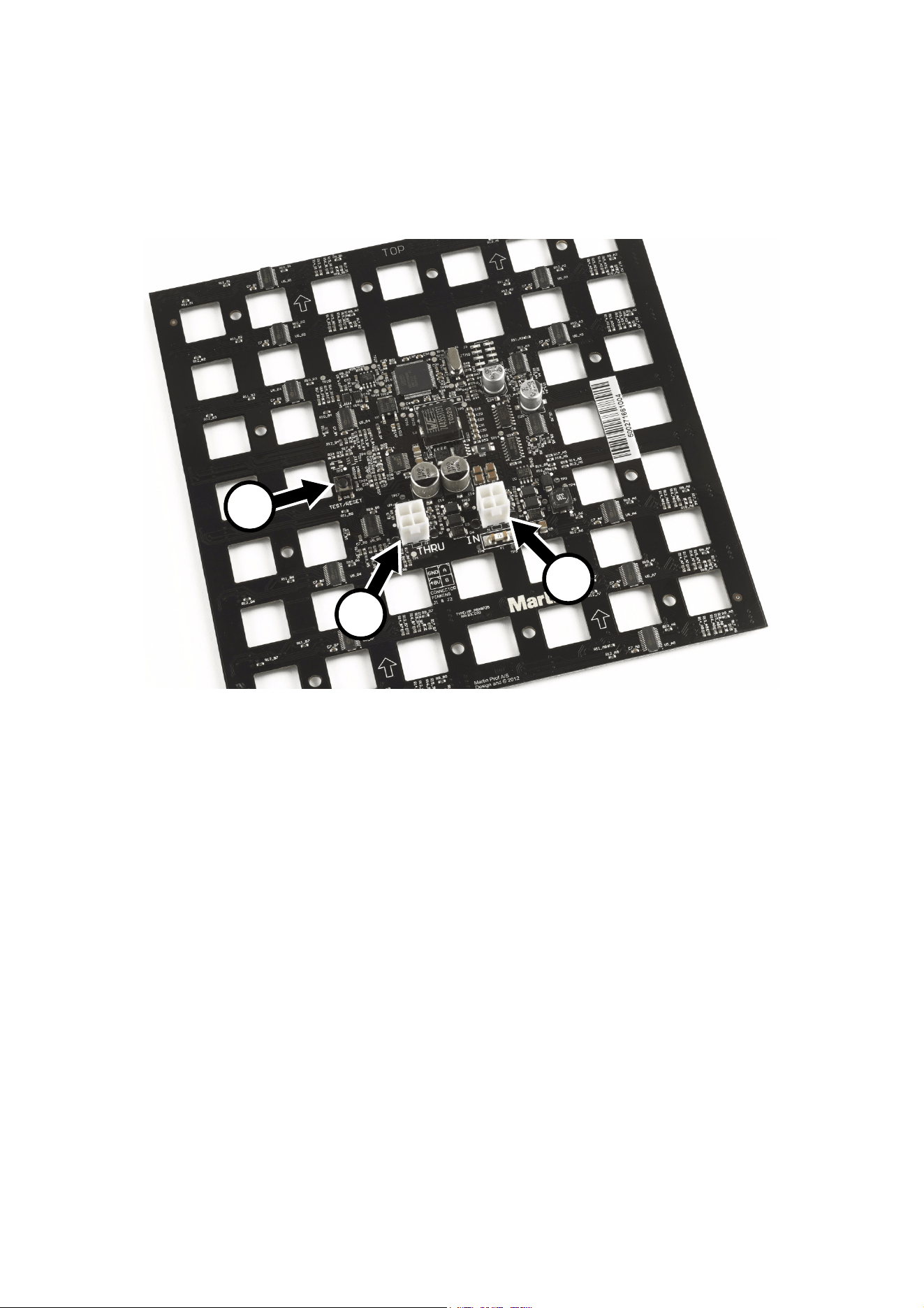
Figure 1: Overview
A - Control button
B - 48 VDC power + data throughput (THRU)
C - 48 VDC power + data input (IN)
Connectors B and C have right-angled design on other models
10 VC-Grid Safety and Installation Guide
Physical installation
Warning! Read “Safety Information” on page 4 and “Precautions to avoid damage” on page 7 before
installing the VC-Grid.
The VC-Grid can be installed in any orientation.
The backs of modules are marked with arrows and the word TOP. To ensure the most evenly matched
optical characteristics when viewing VC-Grids at an angle, install all modules with the arrows facing the
same way. In vertical arrays, install all modules with the arrows pointing upwards and the TOP marking at
the upper edge of the modules.
Allow free airflow around the product and at least 10 mm (0.4 in.) of clearance around the LEDs on the front
surface.
To maintain even pixel spacing across multiple VC-Grids so that they form a seamless display surface,
install them with the following gaps between the edges of modules, both horizontally and vertically:
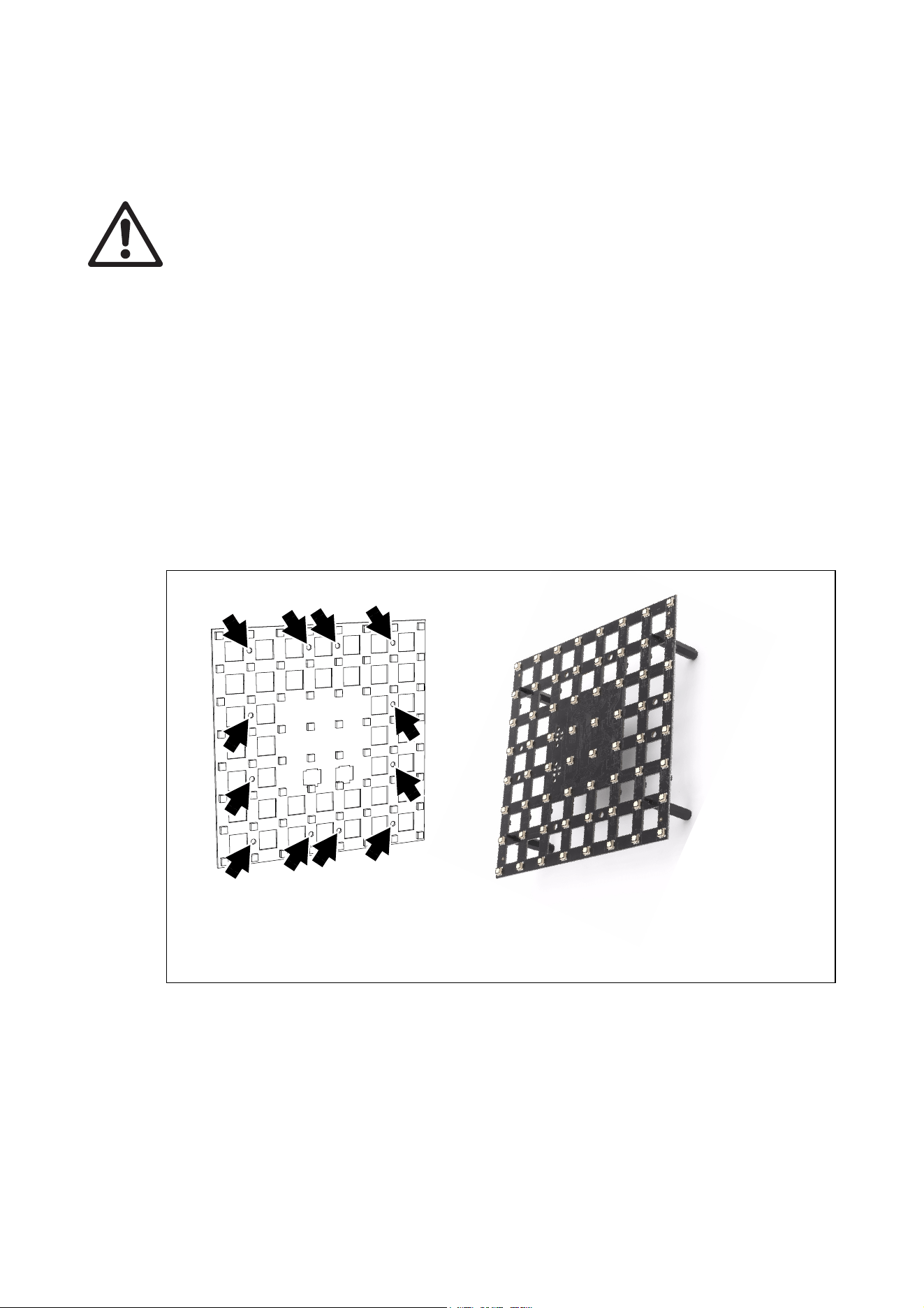
See Figure 2. The VC-Grid can be fastened to a surface or structure using pillar bolts through any four of the
mounting holes (arrowed). Arrange pillar bolts so that they are evenly spaced around the product. Add
non-conductive washers on both sides of the VC-Grid.
• VC-Grid 16x16 15 . . . . 5 mm
• VC-Grid 8x8 25 . . . . . 15 mm
• VC-Grid 8x8 30 . . . . . 20 mm
• VC-Grid 8x8 60 . . . . . 40 mm
• VC-Grid 4x4 60 . . . . . 40 mm
Figure 2: Mounting method
VC-Grid 8x8 25 illustrated
Physical installation 11
Mounting frames
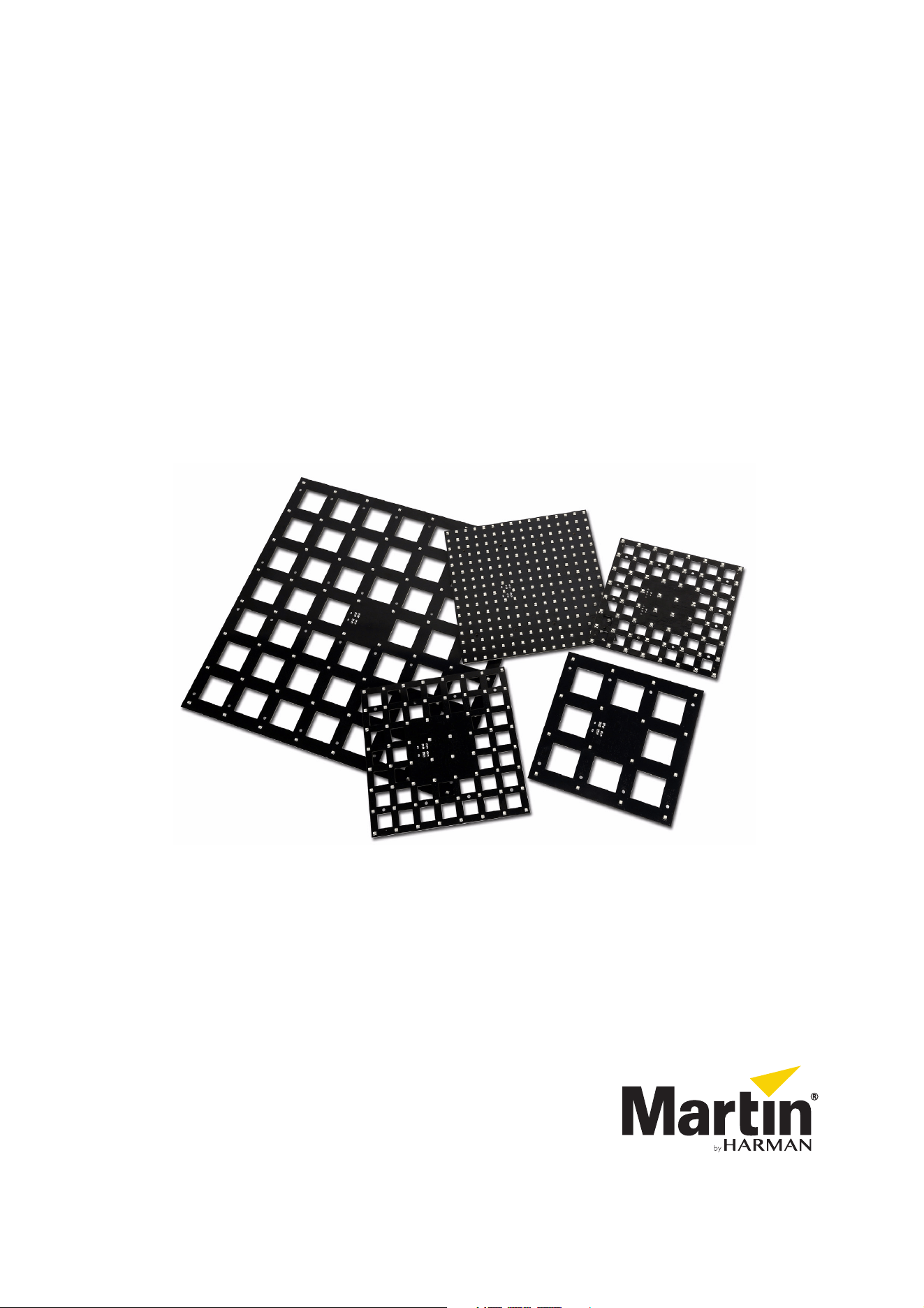
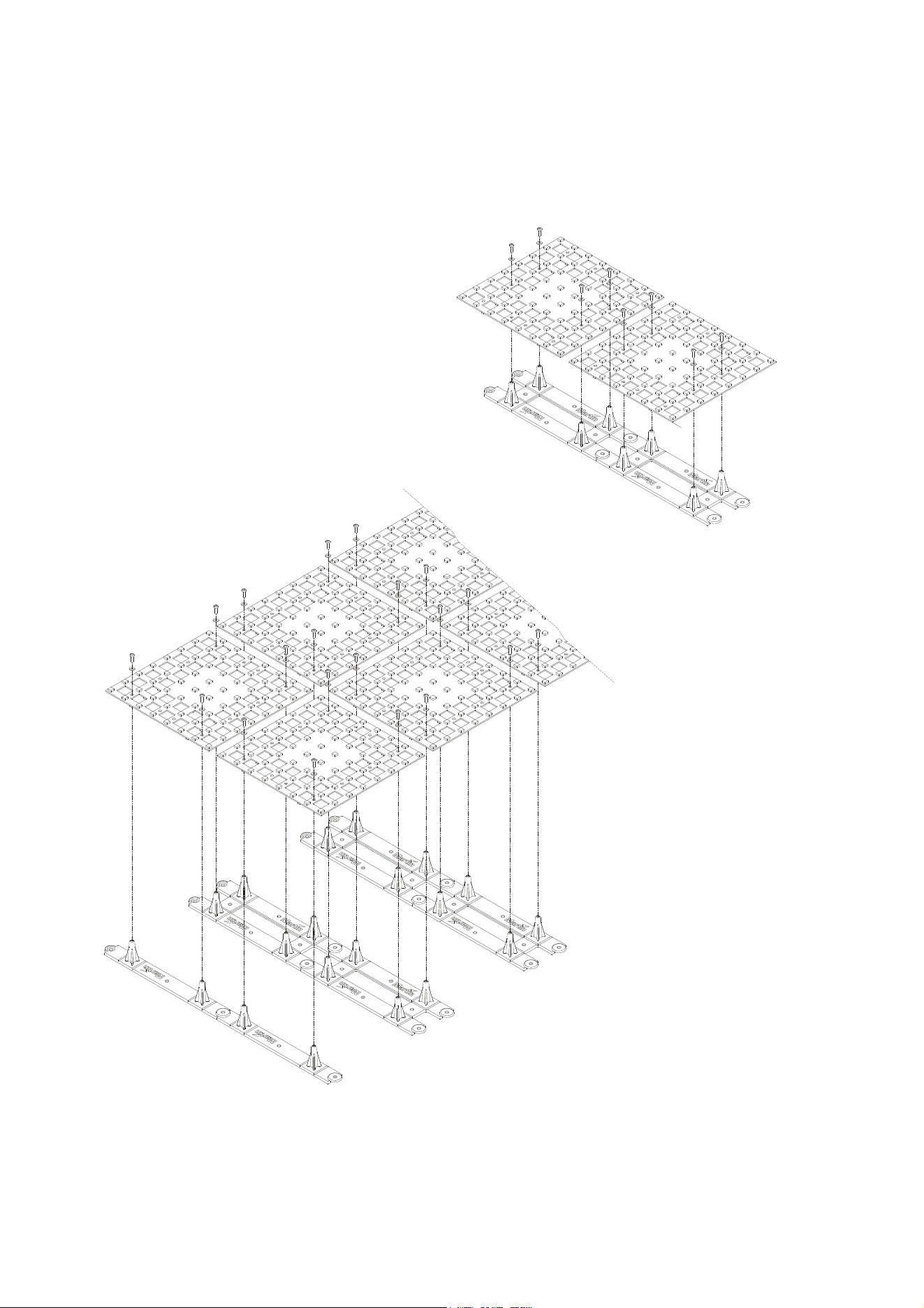
See Figure 3. Mounting frames for the VC-Grid that speed up and simplify the installation process are
available from Martin. See “Mounting accessories” on page 30.
Full instructions for installing mounting frames are supplied with the frames. You can also download them
from the Downloads area of the VC-Grid product webpage at www.martin.com.
Figure 3. Martin VC-Grid Mounting Frames
12 VC-Grid Safety and Installation Guide
System installation
Warning! Read “Safety Information” on page 4 and “Precautions to avoid damage” on page 7 before
installing a VC-Grid system. Pay particular attention to the limits given in ”Protection from electric
shock” on page 4.
Warning! Connect the VC-Grid to only the devices specified in this manual and using only the Martin
cables specified in this manual.
Warning! Do not exceed the maximum numbers of devices that can be connected in chains and
maximum cable lengths specified in ”Protection from electric shock” starting on page 4 and in the
manuals of the other devices in the system.
Important! The VC-Grid is not designed to allow hot-plugging. Shut down power and data before
connecting or disconnecting modules, or you will probably cause damage that is not covered by the
product warranty.
The VC-Grid is designed to display either Martin P3 video or DMX-controlled lighting effects. It automatically
recognizes and responds to either a P3 or a DMX data signal. The next sections explain how to create a
VC-Grid installation to display P3 video data or DMX-controlled lighting effects.
Installing a P3 system
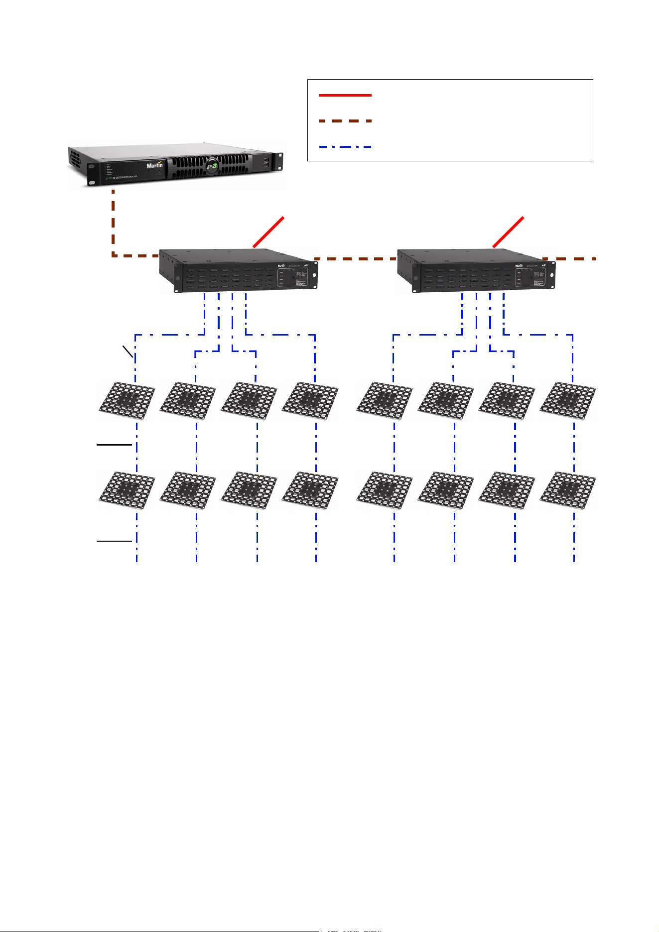
See Figure 5 on page 14 for an overview of a Martin P3 video display system.
The P3 link requires Ethernet Cat 5e or better network cable. The cable run between any two devices on the
link can be up to 100 m (328 ft.) in length. If necessary, a cable run can be extended beyond 100 m by
inserting an unmanaged Ethernet switch or using a fiber-optic system (see the P3 system controller user
manual for details).
To install a system that displays Martin P3 video on VC-Grids, see the P3 system overview in Figure 5 and
follow these directions:
1. Make sure that no devices in the installation can be connected to AC mains power until all installation
work is complete.
2. Read “Safety Information” on page 4 and “Precautions to avoid damage” on page 7.
3. Connect VC-Grid modules together in chains using Martin hybrid PCB-to-PCB cables (see ”VC-Grid to
VC-Grid link cables” on page 30). Connect each cable from the THRU connector of one VC-Grid to the
IN connector on the next VC-Grid to create the chain.
Warning! Do not exceed the maximum lengths for chains given in ”Protection from electric shock” on
page 4.
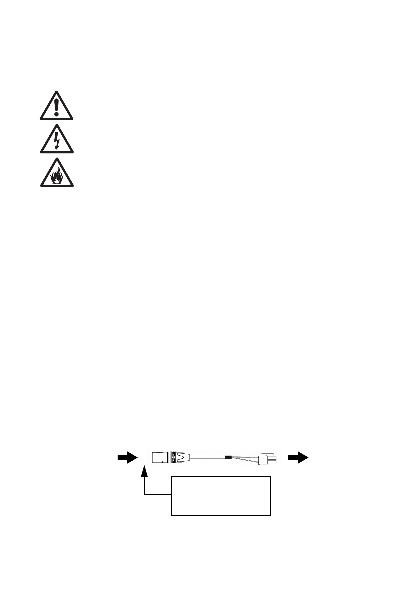
4. Connect each chain of VC-Grids to one of the four 4-pin female XLR hybrid (48 VDC power + P3 data)
outputs on the P3 PowerPort 1500 using a Martin hybrid 4-pin male XLR-to-PCB adapter cable,
P/N 91616035 (see Figure 4).
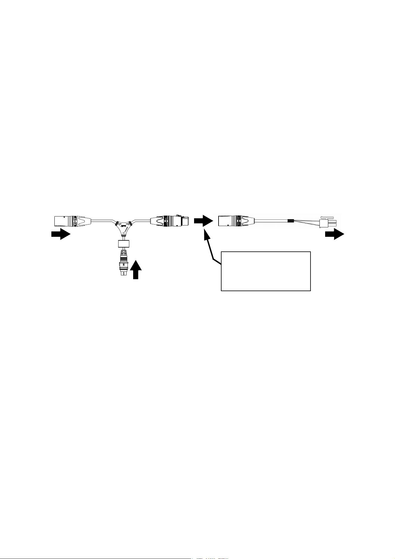
Figure 4: Power and P3 video data input from P3 PowerPort 1500
4-pin male XLR PCB connector
4-pin XLR Hybrid-to-PCB adapter cable, P/N 91616035
Insert 4-pin XLR hybrid
extension cable here if you
need to extend the hybrid cable
run
DC power and
data from P3
PowerPort 1500
DC power and
data to VC-Grid
chain

System installation 13
If necessary, extend the cable by connecting a Martin 4-pin XLR hybrid extension cable to the
Hybrid-to-PCB adapter cable so that you can run the hybrid link to the P3 PowerPort 1500. Suitable
extension cables are available from Martin in various lengths. See ”Extension cables” on page 30.
5. Create a P3 video data link from a Martin P3 system controller such as the P3-050™, P3-150™ or P3
PC™ to the P3 PowerPort (see the products’ user manuals for details).
6. If required, continue the P3 video data link in a daisy-chain by connecting the P3 data throughput of one
P3 PowerPort 1500 to the P3 data input of the next, as described in the P3 PowerPort 1500’s user
manual. You can connect up to fifty P3 PowerPort 1500s in a P3 data daisy-chain like this. If you need to
connect more than fifty, use an unmanaged Ethernet switch to split the P3 data link into branches, each
containing less than fifty P3 PowerPort 1500s.
7. Connect the P3 PowerPort 1500 to AC mains power at 100 - 240 V, 50/60 Hz as described in its user
manual.
8. Connect the P3 system controller to AC mains power and power the controller on.
You can now configure the system at the P3 controller. See”System setup” on page 21.
Note: Use of the Martin P3 PowerPort 1500 to send DC power and video data to VC-Grids via Martin hybrid
cable is the easiest and most economical solution when preparing a VC-Grid installation for P3 video
display. It is possible to use an IP65- or IP66-rated Martin P3 PowerPort 1000 IP device instead of the P3
PowerPort 1500, but this option will require custom-made hybrid cable and will probably be less economical.
If you wish to use a P3 PowerPort 1000 IP in a VC-Grid installation, please contact your Martin supplier for
advice.
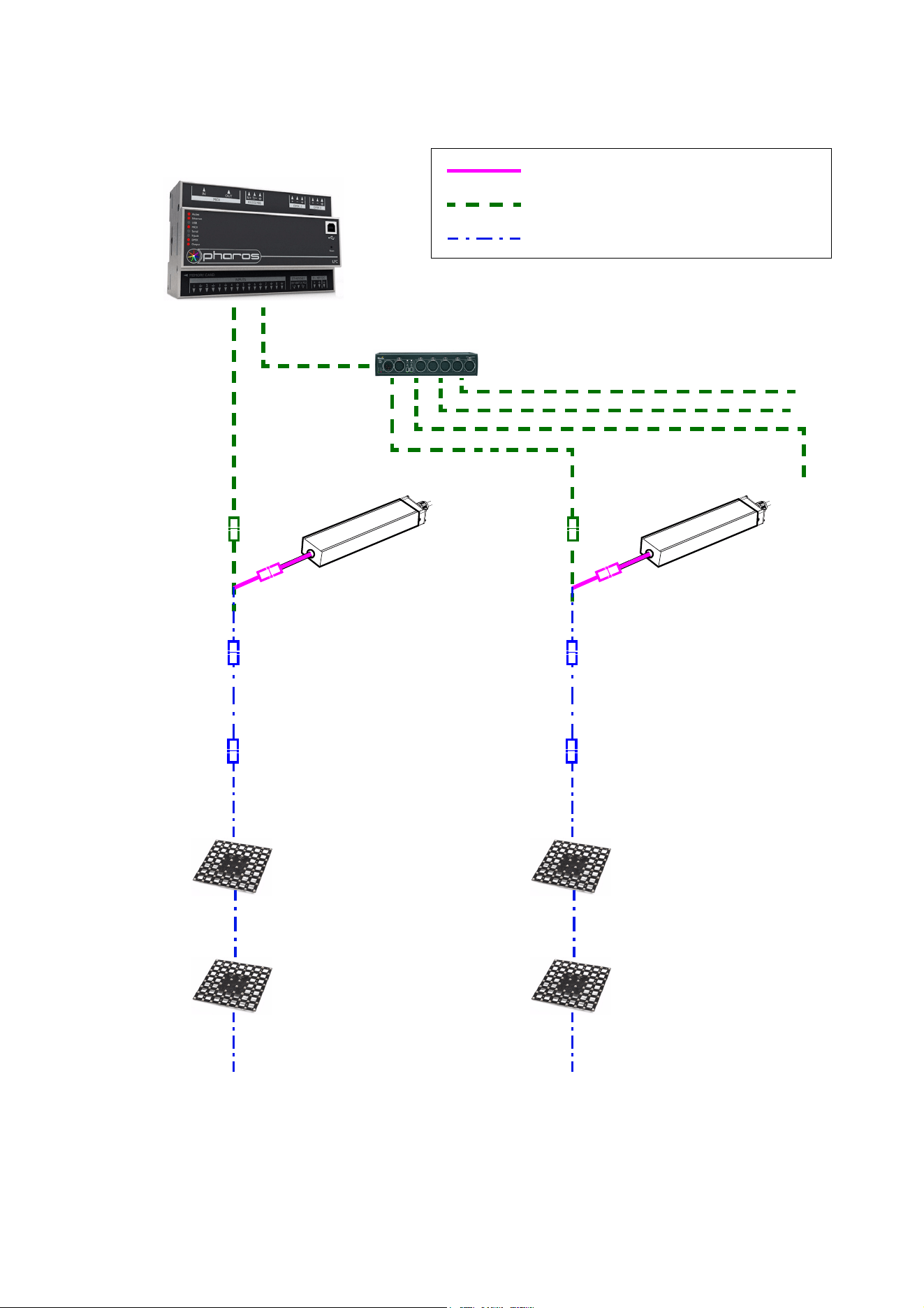
14 VC-Grid Safety and Installation Guide
Max. 4 chains per
P3 PowerPort 1500
AC mains
power
P3 System Controller
P3 PowerPort
1500
P3 PowerPort
1500
AC mains
power
AC mains power
P3 video data link (Ethernet cable)
Hybrid (DC power and data) link
Figure 5: P3 system layout
H
ybri
d-to-
P
CB
a
dapter
c
ab
l
e
Hybrid PCB-
to-PCB cable
Hybrid PCB-
to-PCB cable
See Table 1 on page 5 for maximum permitted number of modules in chain

System installation 15
Installing a DMX-controlled system
In a DMX-controlled system, an RDM-compliant DMX lighting controller sends a DMX control data signal
over a DMX link to the installation, and then over the hybrid link to the VC-Grids.
The DMX link requires DMX cable. It can be maximum 300 m (1000 ft.) in length and must run in one single
daisy-chain, but it can be extended or split into branches using an RDM-compliant amplifier/splitter such as
the Martin RDM 5.5 Splitter™ (P/N 90758150). Alternatively, you can run the DMX signal from the controller
over Ethernet cable using Art-Net protocol and convert it to a DMX-compliant signal with a standard Art-Net
to DMX node.
If you would like assistance with creating a DMX link, your Martin supplier will be glad to advise.
The number of VC-Grids that you can control on one DMX link is limited by the number of DMX channels the
VC-Grids will use and the 512 DMX channels available in one DMX universe at the DMX controller. Each
time you have used 512 channels, you must create a new DMX link that is connected to a new DMX
universe on the controller. Note that this limit applies to the DMX link. The maximum safety limits that apply
to the hybrid link (see “Safety Information” on page 4) take priority and must be respected in all cases.
DC Power options in DMX installations
A DMX-controlled VC-Grid installation can be supplied with DC power from the Martin IP66 PSU 240W
external PSU or from a generic external PSU that can supply DC power at 48 V (the Mean Well SP-480 48,
for example).
The hardware and cables required are slightly different depending on which type of PSU you use to supply
the installation with DC power. The two different types of installation are covered in the next two sections:
• If you are using a Martin IP66 PSU 240W, see ”Installing a DMX system using the Martin IP66 PSU
240W” on page 16.
• If you are using a generic 48 VDC PSU, see ”Installing a DMX system using a generic 48 VDC
external PSU” on page 18.
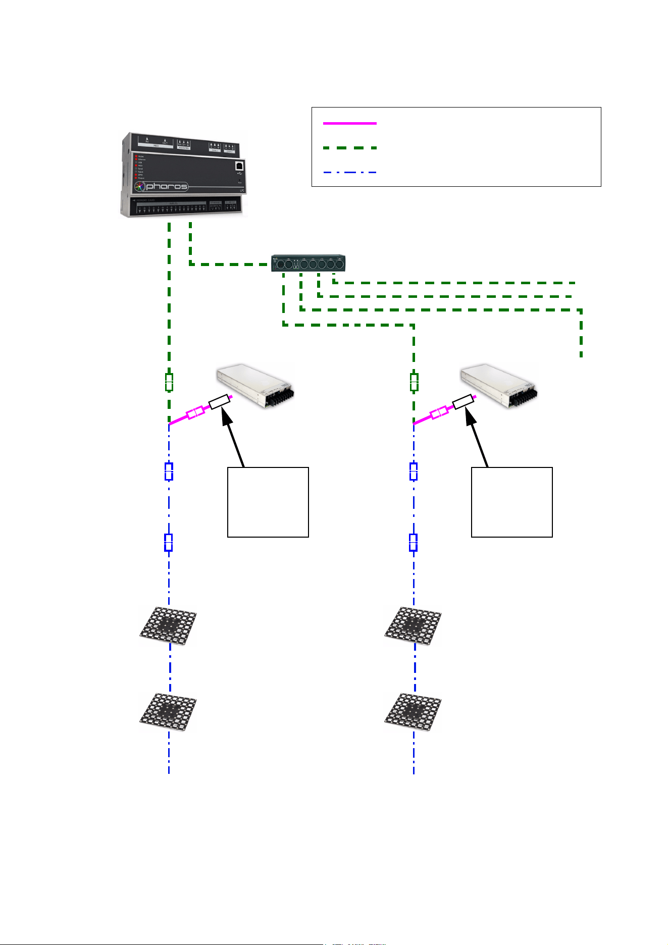
16 VC-Grid Safety and Installation Guide
Installing a DMX system using the Martin IP66 PSU 240W
DMX/RDM Controller
48 VDC power
DMX link (DMX cable)
Hybrid (DC power and data) link
Figure 6: DMX system layout using the Martin IP66 PSU 240W
DMX/RDM Splitter (if used)
Martin IP66 PSU 240W
Hybrid lead-in
Hybrid-to-PCB
adapter cable
cable, Martin
Hybrid extension
cable
(if needed)
Hybrid PCB-
to-PCB cable
Hybrid PCB-
to-PCB cable
Martin IP66 PSU 240W
Hybrid-to-PCB
adapter cable
Hybrid extension
cable
(if needed)
Hybrid PCB-
to-PCB cable
Hybrid PCB-
to-PCB cable
IP66 240W PSU
Hybrid lead-in
cable, Martin
IP66 240W PSU
See Table 2 on page 5 for maximum permitted number of modules in chain
System installation 17
To create a DMX-controlled installation that draws DC power from the Martin IP66 PSU 240W:
1. See Figure 6 on page 16 for an overview of this type of installation
2. Make sure that no devices in the installation can be connected to AC mains power until all installation
work is complete.
3. Read “Safety Information” on page 4 and “Precautions to avoid damage” on page 7.
4. Connect VC-Grids together in daisy-chains using Martin hybrid PCB-to-PCB cables (see ”VC-Grid to
VC-Grid link cables” on page 30). Connect each cable from the THRU connector on one VC-Grid to the
IN connector on the next VC-Grid.
Warning! Do not exceed the maximum permitted number of modules per chain given in Table 2 on
page 5.
5. See Figure 7. Connect a Martin hybrid-to-PCB adapter cable (P/N 91616035) to the first VC-Grid of
each chain.
6. If necessary, you can extend the hybrid link by connecting a Martin 4-pin XLR hybrid extension cable to
the Hybrid-to-PCB adapter cable. Suitable extension cables are available from Martin in various lengths.
See ”Extension cables” on page 30.
7. See Figure 7. Connect the DC power input connector of a Martin IP66 PSU 240W hybrid lead-in cable
(P/N 91616039) to the DC output on the IP66 PSU 240W.
8. Connect the 4-pin female XLR connector on the hybrid lead-in cable to the 4-pin male connector on the
hybrid-to-PCB adapter cable (or on the hybrid extension cable, if you have extended the hybrid link).
9. Connect the 5-pin male XLR connector on the hybrid lead-in cable to a DMX link that carries a DMX
signal from an RDM-compliant DMX controller.
10. Install a mains power cable on the Martin IP66 PSU 240W and connect it to AC mains power.
11. Apply AC mains power to the DMX controller.
You can now configure the system. See ”System setup”on page 21.
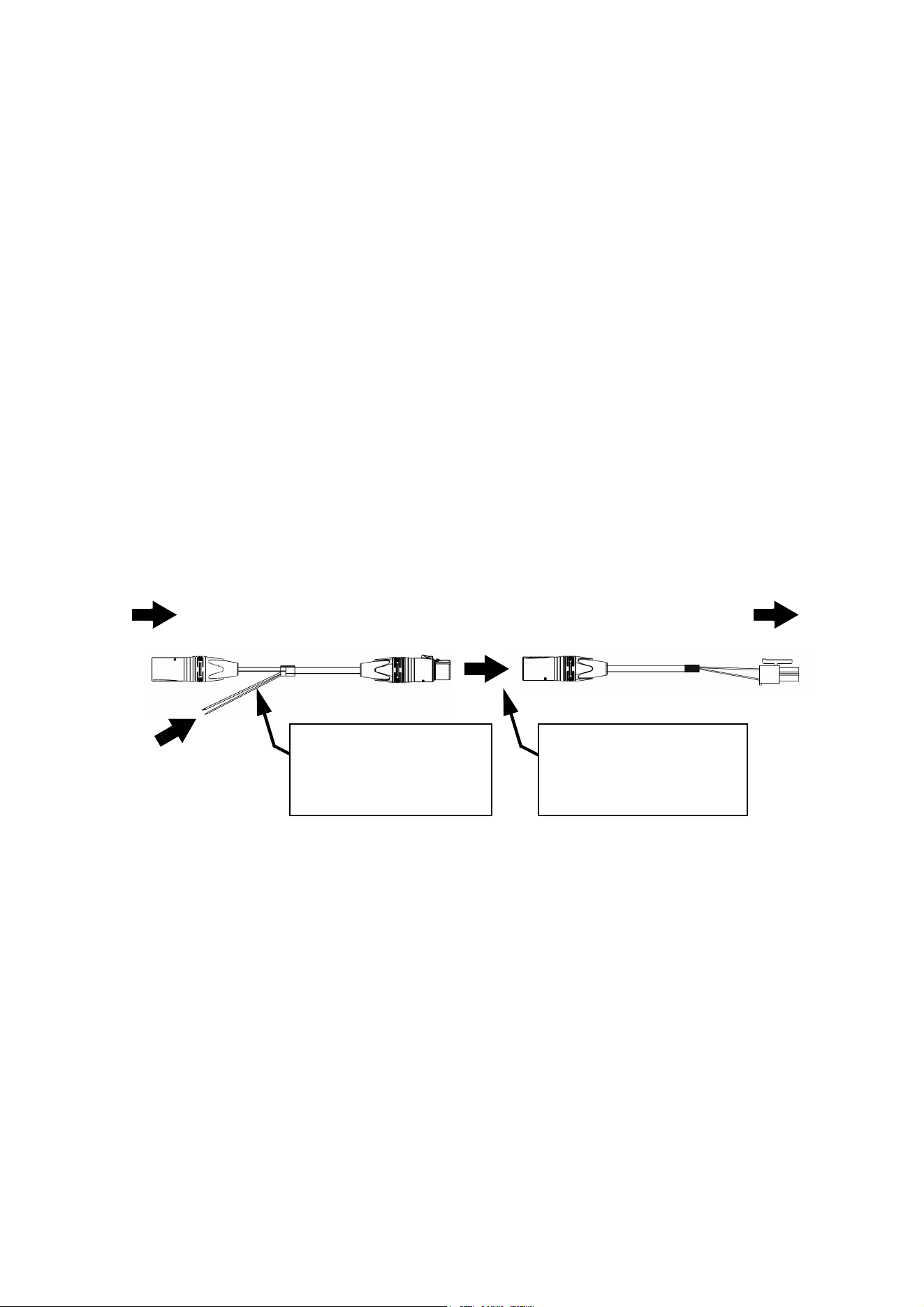
Figure 7: Martin IP66 PSU 240W and DMX connections to a VC-Grid chain
DC power from
To VC-Grid
Hybrid lead-in cable, Martin IP66 PSU 240W, P/N 91616039
chain
5-pin male XLR 4-pin female XLR
4-pin male XLR PCB connector
Hybrid-to-PCB adapter cable, P/N 91616035
Martin IP66 240W PSU
DMX from DMX/RDM
controller
Insert 4-pin XLR hybrid
extension cable here if you
need to extend the cable run
18 VC-Grid Safety and Installation Guide
Installing a DMX system using a generic 48 VDC external PSU
DMX/RDM Controller
48 VDC power
DMX link (DMX cable)
Hybrid (DC power and data) link
Figure 8: DMX system layout using generic external PSU
DMX/RDM Splitter (if used)
Hybrid DC
Hybrid-to-PCB
adapter cable
lead-in cable
Hybrid extension
cable
(if needed)
Hybrid PCB-
to-PCB cable
Hybrid PCB-
to-PCB cable
Hybrid-to-PCB
adapter cable
Hybrid extension
cable
(if needed)
Hybrid PCB-
to-PCB cable
External PSU
Inline fuse
required if PSU
does not have
8 A overcurrent
protection
External PSU
Inline fuse
required if PSU
does not have
8 A overcurrent
protection
Hybrid DC
lead-in cable
Hybrid PCB-
to-PCB cable
See Table 3 on page 6 for maximum permitted number of modules in chain. Do not exceed
PSU output rating.
System installation 19
To create a DMX-controlled installation that draws DC power from a generic 48 VDC PSU:
1. See Figure 8 on page 18 for an overview of this type of installation.
2. Make sure that no devices in the installation can be connected to AC mains power until all installation
work is complete.
3. Read “Safety Information” on page 4 and “Precautions to avoid damage” on page 7.
4. Connect VC-Grids together in chains using Martin hybrid PCB-to-PCB cables (see ”VC-Grid to VC-Grid
link cables” on page 30). Connect each cable from the THRU connector on one VC-Grid to the IN
connector on the next VC-Grid.
Warning! Check the PSU’s DC output power rating in watts and the power consumption figures in watts
for VC-Grid modules given in Table 3 on page 6. Do not create a chain of VC-Grid modules that will
exceed the power rating of the DC output on the PSU. Even if the PSU’s DC output power rating would
be high enough, do not create a chain of VC-Grids that contains more than the maximum permitted
number per chain given in Table 3 on page 6.
5. See Figure 9. Connect a Martin hybrid-to-PCB adapter cable (P/N 91616035) to the first VC-Grid of
each chain.
6. If necessary, you can extend the hybrid link cable run by connecting a Martin 4-pin XLR hybrid extension
cable to the Hybrid-to-PCB adapter cable. Suitable extension cables are available from Martin in various
lengths. See ”Extension cables” on page 30.
7. See Figure 9. If the PSU does not have constant overcurrent protection that will limit current to 8 A on
the DC output used, install an inline fuseholder with a 7.5 A or 8 A fuse on the white (+ve) power wire of
a Martin hybrid lead-in cable (P/N 91616037). A 30 amp automotive-type inline fuseholder with a 7.5 A
blade fuse can be used. Connect the power wires on the lead-in cable to a DC output on the PSU.
Connect the white wire to positive (+ve) and the black wire to negative (-ve).
8. Connect the 4-pin female XLR connector on the hybrid lead-in cable to the 4-pin male connector on the
hybrid-to-PCB adapter cable (or on the hybrid extension cable, if you have extended the hybrid link).
9. Connect the 5-pin male XLR connector on the hybrid lead-in cable to a DMX link that carries a DMX
signal from an RDM-compliant DMX controller.
10. Apply AC mains power to the external PSU.
11. Apply AC mains power to the DMX controller.
You can now configure the system. See ”System setup”on page 21.
Figure 9: Generic PSU and DMX connections to a VC-Grid chain
DC power from
white to +ve, black to -ve
To VC-Grid
Hybrid DC lead-in cable, P/N 91616037
chain
5-pin male XLR 4-pin female XLR
4-pin male XLR PCB connector
Hybrid-to-PCB adapter cable, P/N 91616035
generic PSU
Insert 4-pin XLR hybrid
extension cable here if you
need to extend the cable run
Insert 7.5 A or 8 A inline
fuse here if PSU does not
have 8 A overcurrent
protection
DMX from DMX/RDM
controller

20 VC-Grid Safety and Installation Guide
Connecting additional devices to a VC-Grid chain
Drawing off combined data and DC power from the end of a chain
If you want to continue the hybrid link to carry 48 VDC power and a P3 video or DMX signal from the end of
a VC-Grid chain to other devices, connect a Martin Hybrid Adapter Cable, PCB to 4-pin female XLR, P/N
91616036, to the OUT connector of the last module in the chain.
Warning! If you draw off DC power from the end of a VC-Grid chain and connect additional devices,
respect the maximum safe power rating of the power source that you use to supply all the devices
with DC power. Calculate the power consumption of the VC-Grid chain using the figures in Table 3
on page 6, then add the power consumption of each device that you add to the end of the chain. As
soon as you reach 360 W – or the maximum power rating of the device that you use to supply the
chain with DC power if this rating is lower than 360 W – you must stop adding devices and create a
new chain that draws DC power from a new source.
Drawing off a DMX signal from the end of a chain
If you want to continue the DMX link to carry a DMX signal from the end of a VC-Grid chain to other devices,
connect a Martin Hybrid Adapter Cable, PCB to 4-pin female XLR, P/N 91616036, to the OUT connector of
the last module in the chain.
Then, to connect to a standard DMX link that uses 5-pin XLR connectors, add a Martin Data Out/Thru
Adapter Cable, 4-pin male XLR to 5-pin female XLR, P/N 91616040. This adapter cable relays the DMX
data signal only, it does not collect DC power at its 4-pin male XLR connector.

System setup 21
System setup
Warning! Read “Safety Information” on page 4 and “Precautions to avoid damage” on page 7 before
applying power to the VC-Grid.
Setting up for P3 display
A Martin P3™ system allows video to be displayed on an installation that consists of or includes VC-Grid
modules. When a P3 controller is connected to the P3 data link and the installation is powered on, you can
set up all the devices on the link from the P3 controller. See the P3 controller user manual for details.
Setting up for DMX control
A DMX system gives 0 - 100% variable intensity control. Varying the intensity of red, blue and green LEDs in
RGB products provides RGB color mixing. Setting red, blue and green to 100% intensity gives white, with
the option of adjusting color temperature using the red and blue LEDs.
You can set up and control a VC-Grid installation over the data link using an RDM-compatible DMX
controller.
DMX control channels
DMX controllers send control data to devices over DMX control channels in DMX universes. One DMX
universe has 512 channels available.
One DMX channel is required for each control parameter of each element in the installation. An element can
consist of an individual pixel, a VC-Grid module, or a group of modules, depending on how you set up the
VC-Grids. A control parameter can consist of red intensity, for example. So, red intensity control of one
element in an installation uses one channel. RGB control of a VC-Grid installation requires three channels
per element.
• If you set a VC-Grid to individual pixel control, you can control each LED on that VC-Grid as an individual
pixel using its own DMX channels – three channels per pixel.
• If you set a VC-Grid to module control, you can control all the LEDs on that VC-Grid as a group using the
same three DMX channels. Individual control of the pixels on that VC-Grid module is impossible.
• If you set multiple VC-Grids to module control and also set up those VC-Grids to use the same DMX
channels, you can control all the VC-Grids as a group using the same three DMX channels. Individual
control of the pixels or modules in the group is impossible.
Type of VC-Grid module
DMX channels per module,
module control
DMX channels per module,
individual pixel control
VC-Grid 16x16 15 RGB 3
192 (LEDs controlled in
groups of four)
VC-Grid 8x8 25 RGB 3 192
VC-Grid 8x8 30 RGB 3 192
VC-Grid 8x8 60 RGB 3 192
VC-Grid 4x4 60 RGB 3 48
Table 5: Number of DMX channels required per VC-Grid module

22 VC-Grid Safety and Installation Guide
Calculating the number of DMX channels required
A VC-Grid installation uses the three DMX channels required by each element (individual pixel, module or
group of modules) multiplied by the total number of elements in the installation. For example, an installation
containing fifty VC-Grid 8x8 RGB modules will require:
• 3 DMX channels if the entire installation is controlled as one group,
• 3 channels x 10 groups = 30 DMX channels if the installation is divided into ten groups that are controlled
individually,
• 3 channels x 50 modules = 150 DMX channels if each of the fifty modules is controlled as an individual
group, and
• 3 channels x 50 modules x 64 pixels = 9600 DMX channels if each of the 3200 pixels is controlled
individually (in this example, 19 DMX universes will be required because one DMX universe has 512
channels).
Pixel and module modes
If you set a VC-Grid to pixel mode, each pixel on the module is controlled individually (apart from the
VC-Grid 16x16, where pixels are controlled in groups of four).
If you set a VC-Grid to module mode, all the pixels on the module are controlled together as one group.
The interfaces of RDM-compliant controllers vary depending on the producer, but you should be able to find
the pixel and module mode options in the Settings or Options area of your controller.
Individual and grouped control can be mixed freely in an installation. For example, some VC-Grid modules
can be set up for individual pixel control, other modules can be set up for individual module control, and
other modules can be put into groups for grouped control of multiple modules.
DMX addresses
To prepare an installation for DMX control, you need to set it up using an RDM-compliant DMX controller so
that each individually controlled element (pixel, module or group of modules) will receive instructions from
the controller on its own DMX channels. The DMX address (also known as the control address or start
channel) is the first of these channels. If an element requires more than one DMX channel, it uses the DMX
address channel and the channels immediately above it. For example, if you set a VC-Grid RGB module to
module mode so that you control all its pixels as one group, and if you set it to DMX address 1, it will use
DMX channels 1 - 3. Channel 4 will be available for use as a DMX address for the next device.
If you set a VC-Grid to pixel mode so that you can control individual pixels, its LEDs use DMX addresses
according to a ‘left-to-right, then down’ numbering system (like the reading order of the words on this page).
For example, if one VC-Grid 8x8 RGB module is set to pixel control and set to DMX address 1, each of the
module’s 64 LEDs will use 3 channels, and the module will use DMX channels 1 - 192 (Channel 1 -3 for the
top-left pixel, channels 4 - 6 for the next pixel on the right etc. until it reaches channels 190 - 192 for the last
pixel at the bottom on the right. Channel 193 will be available for use as a DMX address for the next device.
If you set a VC-Grid to module mode so that you control it as one module, it will use three DMX channels as
described above. If you want to create a group of modules that you always control together, give all those
modules the same DMX address. All modules that have the same DMX address will receive the same
instructions and behave identically.
Setting up via RDM
Using an RDM-compliant DMX controller, you can communicate with the VC-Grid modules on the DMX data
link via RDM. You can:
• Retrieve data
• Set the DMX addresses of the groups or pixels on the link
• Set modules to grouped or pixel control modes (see above)
• Apply various setup options.
See the controller’s user manual for details of how to retrieve information from and send commands to the
VC-Grid.

Using the VC-Grid 23
Using the VC-Grid
Warning! Read “Safety Information” on page 4 and “Precautions to avoid damage” on page 7 on
before applying power to the VC-Grid.
Do not use the VC-Grid if the ambient temperature exceeds 45° C (113° F) or falls below -20° C (-4° F).
See page 8. Monitor component temperatures with reference to Table 4 and be prepared to provide
fan-assisted cooling if necessary.
P3 display
The VC-Grid will display video from all common video sources sent via a P3 controller. See the P3 controller
documentation for details.
DMX control
The VC-Grid will display effects controlled by DMX and communicate with an RDM-compatible DMX
controller.
Local control button
The small control button on the back of the VC-Grid (see Figure 1 on page 9) lets you display the product’s
status, test the LEDs and reset the VC-Grid.
Status display
To display a VC-Grid module’s status, press the control button once. Four LEDs in the top-left corner of the
module will give one of the indications listed in the following table for a few seconds:
Color Output Indication Action required
Blue Constant
Busy (e.g. booting up or writing to
flash memory).
Wait a moment for normal operation
to be resumed.
Red Constant
Error. The VC-Grid has encountered
a fatal error and can not run.
Perform a factory reboot, followed by
a firmware upload.
Red Flashing No control source detected.
Connect a P3 system controller or
DMX source to the network.
Green Flashing
Ready. VC-Grid connected to P3
controller but not receiving valid P3
data stream.
Set up the P3 controller to use the
VC-Grid.
Green Constant Running normally in P3 mode. None.
Cyan Flashing
Ready. VC-Grid connected to DMX
controller but not receiving valid
DMX data stream.
Set up the DMX controller to use the
VC-Grid.
Cyan Constant Running normally in DMX mode. None.
Table 6: Status information

24 VC-Grid Safety and Installation Guide
Testing, rebooting and returning to defaults
The table below lists the functions of the control button on each VC-Grid module.
Test patterns are stored in onboard memory. This lets you test the LEDs without an external controller.
However, test patterns can also be called up on P3 system controllers and the P3 PowerPort 1500
Button action Function
Short press The first press displays status as shown in Table 6 for a few seconds.
The next presses display the following test patterns on the LEDs (one
short press scrolls to next pattern):
- Calibrated white
- Full red
- Full green
- Full blue
- Vertical scrolling gradient
- Dimmed (20%) uncalibrated white
Press and hold until
all LEDs light blue
Reboot the VC-Grid.
Press and hold until
all LEDs light white
Return the VC-Grid to its default factory firmware.
Table 7: Control button functions

Service and maintenance 25
Service and maintenance
Warning! Read “Safety Information” on page 4 and “Precautions to avoid damage” on page 7 before
carrying out service on the VC-Grid.
Warning! Isolate the installation from AC mains power before servicing.
Warning! Refer any service operation not described in this manual to a qualified service technician.
Important! Excessive dirt buildup causes overheating and a risk of short-circuits and may damage
the product. Damage caused by inadequate cleaning is not covered by the product warranty.
Important! The VC-Grid is not designed to allow hot-plugging. Shut down power and data before
connecting or disconnecting modules, or you will probably cause damage that is not covered by the
product warranty.
The user will need to clean the VC-Grid periodically. All other service operations on the VC-Grid must be
carried out by Martin or its approved service agents.
Installation, on-site service and maintenance can be provided worldwide by the Martin Professional Global
Service organization and its approved agents, giving owners access to Martin’s expertise and product
knowledge in a partnership that will ensure the highest level of performance throughout the product’s
lifetime. Please contact your Martin supplier for details.
Cleaning
Cleaning schedules vary greatly depending on the operating environment. It is therefore impossible to
specify precise cleaning intervals for the VC-Grid. In extreme cases, the product may require cleaning after
surprisingly few hours of operation. Environmental factors that may result in a need for frequent cleaning
include:
• Use of smoke or fog machines.
• High airflow rates (near air conditioning vents, for example).
• Presence of cigarette smoke.
• Airborne dust (from stage effects, building structures and fittings or the natural environment in outdoor
locations, for example).
If one or more of these factors is present, inspect products soon after installing them to see whether
cleaning is necessary. Check again at frequent intervals. This procedure will allow you to assess cleaning
requirements in your particular situation. If in doubt, consult your Martin dealer about a suitable
maintenance schedule.
Important! Electrostatic discharges may cause damage. Do not touch the VC-Grid with fingers or a compressed
air nozzle.
To clean the product, use low-pressure compressed air to gently remove dust and loose particles from the
front and back of the product. Avoid touching the product’s conductive surfaces and electronic components.
Installing new software
It may be necessary to upload new software (i.e. device firmware) to the VC-Grid if it appears to have a
software-related fault or if you want to update to a newer software version.
Software for Martin products is available from the Martin website. The VC-Grid software can be installed
from the P3 System Controller over the P3 data link. See the P3 System Controller user manual for software
installation instructions.

26 VC-Grid Safety and Installation Guide
Troubleshooting
Problem Probable cause(s) Remedy
Control is lost and pressing
control button causes VC-Grid
to show constant or flashing red
status indication.
Error has occurred.
Check that system is correctly connected, set up
and running.
Hold control button pressed in until it turns blue,
then release, to reboot VC-Grid.
Restart P3 or DMX controller.
Product is completely dead.
No DC power to product. Check 48 VDC power supply and cables
Internal fault.
Disconnect from power. Do not attempt repairs
yourself. Contact Martin Service or an authorized
Martin service partner for assistance.
VC-Grid does not display as
intended.
Bad 48 VDC power transmission.
Inspect connections and cables. Correct poor
connections. Repair or replace damaged cables.
Bad data transmission.
Inspect connections and cables. Correct poor
connections. Repair or replace damaged cables.
Incorrect mapping or addressing of products. Check product address and controller settings.
Product in installation is defective and is
disturbing data transmission.
Substitute known good products one at a time until
normal operation is regained. Have faulty product
serviced by Martin Service.
Table 8: Troubleshooting

Specifications 27
Specifications
Physical
VC-Grid 16x16 15
Pixel layout. . . . . . . . . . . . . . . . . . . . . . . . . . . . . . . . . . . . . . . . . . . . . . . . . . . . . . . . . . . . . . . . . . . . . . 16x16
Pixel pitch. . . . . . . . . . . . . . . . . . . . . . . . . . . . . . . . . . . . . . . . . . . . . . . . . . . . . . . . . . . . . . . .15 mm (0.6 in.)
Length . . . . . . . . . . . . . . . . . . . . . . . . . . . . . . . . . . . . . . . . . . . . . . . . . . . . . . . . . . . . . . . . 240 mm (9.4 in.)*
Width . . . . . . . . . . . . . . . . . . . . . . . . . . . . . . . . . . . . . . . . . . . . . . . . . . . . . . . . . . . . . . . . . 240 mm (9.4 in.)*
Height . . . . . . . . . . . . . . . . . . . . . . . . . . . . . . . . . . . . . . . . . . . . . . . . . . . . . . . . . . . . . . . . . .15 mm (0.6 in.)
Weight . . . . . . . . . . . . . . . . . . . . . . . . . . . . . . . . . . . . . . . . . . . . . . . . . . . . . . . . . . . . . . . . . 311 g (11.0 oz.)
*Including 5 mm (0.2in.) module-to-module gap
VC-Grid 8x8 25
Pixel layout. . . . . . . . . . . . . . . . . . . . . . . . . . . . . . . . . . . . . . . . . . . . . . . . . . . . . . . . . . . . . . . . . . . . . . . . 8x8
Pixel pitch. . . . . . . . . . . . . . . . . . . . . . . . . . . . . . . . . . . . . . . . . . . . . . . . . . . . . . . . . . . . . . . .25 mm (1.0 in.)
Length . . . . . . . . . . . . . . . . . . . . . . . . . . . . . . . . . . . . . . . . . . . . . . . . . . . . . . . . . . . . . . . . 200 mm (7.9 in.)*
Width . . . . . . . . . . . . . . . . . . . . . . . . . . . . . . . . . . . . . . . . . . . . . . . . . . . . . . . . . . . . . . . . . 200 mm (7.9 in.)*
Height . . . . . . . . . . . . . . . . . . . . . . . . . . . . . . . . . . . . . . . . . . . . . . . . . . . . . . . . . . . . . . . . . .18 mm (0.7 in.)
Weight . . . . . . . . . . . . . . . . . . . . . . . . . . . . . . . . . . . . . . . . . . . . . . . . . . . . . . . . . . . . . . . . . . 140 g (4.9 oz.)
*Including 15 mm (0.6 in.) module-to-module gap
VC-Grid 8x8 30
Pixel layout. . . . . . . . . . . . . . . . . . . . . . . . . . . . . . . . . . . . . . . . . . . . . . . . . . . . . . . . . . . . . . . . . . . . . . . . 8x8
Pixel pitch. . . . . . . . . . . . . . . . . . . . . . . . . . . . . . . . . . . . . . . . . . . . . . . . . . . . . . . . . . . . . . . .30 mm (1.2 in.)
Length . . . . . . . . . . . . . . . . . . . . . . . . . . . . . . . . . . . . . . . . . . . . . . . . . . . . . . . . . . . . . . . . 240 mm (9.4 in.)*
Width . . . . . . . . . . . . . . . . . . . . . . . . . . . . . . . . . . . . . . . . . . . . . . . . . . . . . . . . . . . . . . . . . 240 mm (9.4 in.)*
Height . . . . . . . . . . . . . . . . . . . . . . . . . . . . . . . . . . . . . . . . . . . . . . . . . . . . . . . . . . . . . . . . . .15 mm (0.6 in.)
Weight . . . . . . . . . . . . . . . . . . . . . . . . . . . . . . . . . . . . . . . . . . . . . . . . . . . . . . . . . . . . . . . . . . 157 g (5.5 oz.)
*Including 20 mm (0.8 in.) module-to-module gap
VC-Grid 8x8 60
Pixel layout. . . . . . . . . . . . . . . . . . . . . . . . . . . . . . . . . . . . . . . . . . . . . . . . . . . . . . . . . . . . . . . . . . . . . . . . 8x8
Pixel pitch. . . . . . . . . . . . . . . . . . . . . . . . . . . . . . . . . . . . . . . . . . . . . . . . . . . . . . . . . . . . . . . .60 mm (2.4 in.)
Length . . . . . . . . . . . . . . . . . . . . . . . . . . . . . . . . . . . . . . . . . . . . . . . . . . . . . . . . . . . . . . . . . . . . . . .480 mm*
Width . . . . . . . . . . . . . . . . . . . . . . . . . . . . . . . . . . . . . . . . . . . . . . . . . . . . . . . . . . . . . . . . . . . . . . . .480 mm*
Height . . . . . . . . . . . . . . . . . . . . . . . . . . . . . . . . . . . . . . . . . . . . . . . . . . . . . . . . . . . . . . . . . .15 mm (0.6 in.)
Weight . . . . . . . . . . . . . . . . . . . . . . . . . . . . . . . . . . . . . . . . . . . . . . . . . . . . . . . . . . . . . . . . . 500 g (17.6 oz.)
*Including 40 mm (1.6 in.) module-to-module gap
VC-Grid 4x4 60
Pixel layout. . . . . . . . . . . . . . . . . . . . . . . . . . . . . . . . . . . . . . . . . . . . . . . . . . . . . . . . . . . . . . . . . . . . . . . . 4x4
Pixel pitch. . . . . . . . . . . . . . . . . . . . . . . . . . . . . . . . . . . . . . . . . . . . . . . . . . . . . . . . . . . . . . . .60 mm (2.4 in.)
Length . . . . . . . . . . . . . . . . . . . . . . . . . . . . . . . . . . . . . . . . . . . . . . . . . . . . . . . . . . . . . . . . . . . . . . .240 mm*
Width . . . . . . . . . . . . . . . . . . . . . . . . . . . . . . . . . . . . . . . . . . . . . . . . . . . . . . . . . . . . . . . . . . . . . . . .240 mm*
Height . . . . . . . . . . . . . . . . . . . . . . . . . . . . . . . . . . . . . . . . . . . . . . . . . . . . . . . . . . . . . . . . . .15 mm (0.6 in.)
Weight . . . . . . . . . . . . . . . . . . . . . . . . . . . . . . . . . . . . . . . . . . . . . . . . . . . . . . . . . . . . . . . . . . 123 g (4.3 oz.)
*Including 40 mm (1.6 in.) module-to-module gap
Control and programming
Control options. . . . . . . . . . . . . . . . . . . . . . . . . . . . . . . . . . . . . . . . . Martin P3™ System Controller or DMX
Protocol detection . . . . . . . . . . . . . . . . . . . . . . . . . . . . . . . . . . . . . . . . . . . . . . . . . . . . . . . . . . . . . Automatic
Control modes . . . . . . . . . . . . . . . . . . . . . . . . . . . . . . . . . . . . . . . . . . . . . . . . . . . . . . . . . . Pixel and module
Setting and addressing . . . . . . . . . . . . . . . . . . . . .P3 System controller or RDM-compliant DMX controller
Control resolution. . . . . . . . . . . . . . . . . . . . . . . . . . . . . . . . . 16-bit (P3) or 8-bit (DMX) control of each color
Color and intensity calibration . . . . . . . . . . . . . . . . . . . . . . . . . . . . . . . . . . . . . . . . . . . . . . . . . . . .Pixel-level
Video signal compliance . . . . . . . . . . . . . . . . . . . . . . . . . . . . . . . . . Martin P3™ proprietary video protocol
DMX compliance . . . . . . . . . . . . . . . . . . . . . . . . . . . . . . . . . . . . . . . . . . . . . . . . . . . . . . . USITT DMX512-A
RDM compliance . . . . . . . . . . . . . . . . . . . . . . . . . . . . . . . . . . . . . . . . . . . . . . . . . . . . . . . ANSI/ESTA E1.20
Firmware update . . . . . . . . . . . . . . . . . . . . . . . . . . . . . . . . . . . . . . . . . . . . . . . . . .Via P3 System Controller

28 VC-Grid Safety and Installation Guide
DMX channels used
VC-Grid 16x16 15 RGB, pixel mode (groups of 4 pixels). . . . . . . . . . . . . . . . . . . . . . . . . . . . . . . . . . . . .192
VC-Grid 16x16 15 RGB, module mode . . . . . . . . . . . . . . . . . . . . . . . . . . . . . . . . . . . . . . . . . . . . . . . . . . . .3
VC-Grid 8x8 25 RGB, pixel mode . . . . . . . . . . . . . . . . . . . . . . . . . . . . . . . . . . . . . . . . . . . . . . . . . . . . . . 192
VC-Grid 8x8 25 RGB, module mode . . . . . . . . . . . . . . . . . . . . . . . . . . . . . . . . . . . . . . . . . . . . . . . . . . . . . . 3
VC-Grid 8x8 30 RGB, pixel mode . . . . . . . . . . . . . . . . . . . . . . . . . . . . . . . . . . . . . . . . . . . . . . . . . . . . . . 192
VC-Grid 8x8 30 RGB, module mode . . . . . . . . . . . . . . . . . . . . . . . . . . . . . . . . . . . . . . . . . . . . . . . . . . . . . . 3
VC-Grid 8x8 60 RGB, pixel mode . . . . . . . . . . . . . . . . . . . . . . . . . . . . . . . . . . . . . . . . . . . . . . . . . . . . . . 192
VC-Grid 8x8 60 RGB, module mode . . . . . . . . . . . . . . . . . . . . . . . . . . . . . . . . . . . . . . . . . . . . . . . . . . . . . . 3
VC-Grid 4x4 60 RGB, pixel mode . . . . . . . . . . . . . . . . . . . . . . . . . . . . . . . . . . . . . . . . . . . . . . . . . . . . . . .48
VC-Grid 4x4 60 RGB, module mode . . . . . . . . . . . . . . . . . . . . . . . . . . . . . . . . . . . . . . . . . . . . . . . . . . . . . . 3
Control/user interface
Device status . . . . . . . . . . . . . . . . . . . . . . . . . . . . . . . . . . . . . . . . . . . . . . . Visual indication via LED display
Device test . . . . . . . . . . . . . . . . . . . . . . . . . . . . . . . . . . . . . . Control pushbutton calls up local test patterns
Device reset . . . . . . . . . . . . . . . . . . . . . . . . . . . . . . . . . . . . . . . . . . . . . . . . . . . . . . . . . . .Control pushbutton
Video processing
Brightness control
Gamma correction and control
Color temperature control
Color gamut control
Calibration processing
Synchronization
Optics
Viewing angle. . . . . . . . . . . . . . . . . . . . . . . . . . . . . . . . . . . . . . . . . . . . . . . . . . . . . . . . . . . . . . . 120° x 120°
Minimum LED lifetime . . . . . . . . . . . . . . . . . . . . . . . . . . . . . . . . . 50 000 hours (to >70% luminous output)*
*Obtained under manufacturer´s test conditions
System Integration
P3 PowerPort 1500™ . . . . . . . . . . . . . . . . . . . . . . . . . . . . . . . . . . . . . . . . . . . . . . . . . . . . . . P/N 90721040
See www.martin.com for latest information
Construction
Base. . . . . . . . . . . . . . . . . . . . . . . . . . . . . . . . . . . . . . . . . . . . . . . . . . . . . . . . . . . . . Black FR4 circuit board
Protection rating. . . . . . . . . . . . . . . . . . . . . . . . . . . . . . . . . . . . . . . . . . . . . . . . . . . . . . . . . . . . . . . . . . . IP20
RoHS compliant
Transparency through module (unmasked area)
VC-Grid 16x16 15 . . . . . . . . . . . . . . . . . . . . . . . . . . . . . . . . . . . . . . . . . . . . . . . . . . . . . . . . . . . . . . . . . . 0%
VC-Grid 8x8 25 . . . . . . . . . . . . . . . . . . . . . . . . . . . . . . . . . . . . . . . . . . . . . . . . . . . . . . . . . . . . . . . . . . . 37%
VC-Grid 8x8 30 . . . . . . . . . . . . . . . . . . . . . . . . . . . . . . . . . . . . . . . . . . . . . . . . . . . . . . . . . . . . . . . . . . . 44%
VC-Grid 8x8 60 . . . . . . . . . . . . . . . . . . . . . . . . . . . . . . . . . . . . . . . . . . . . . . . . . . . . . . . . . . . . . . . . . . . 49%
VC-Grid 4x4 60 . . . . . . . . . . . . . . . . . . . . . . . . . . . . . . . . . . . . . . . . . . . . . . . . . . . . . . . . . . . . . . . . . . . 53%
Installation
Orientation . . . . . . . . . . . . . . . . . . . . . . . . . . . . . . . . . . . . . . . . . . . . . . . . . . . . . . . . . . . . . . . . . . . . . . . .Any
Mounting method . . . . . . . . . . . . . . . . . . . . . . . . . . . . . . . . . . . . . . . . . . . . . . . . . Mounting holes in module
Minimum clearance around front surface. . . . . . . . . . . . . . . . . . . . . . . . . . . . . . . . . . . . . . . .10 mm (0.4 in.)
See earlier in this manual for maximum number of VC-Grid modules that can be safely interconnected in
one chain
Connections
Power & data input. . . . . . . . . . . . . . . . . . . . . . . . . . . . . . . . . . . . . . . . . . 4-pin Molex male PCB connector
Power & data thru . . . . . . . . . . . . . . . . . . . . . . . . . . . . . . . . . . . . . . . . . 4-pin Molex female PCB connector
Hot-plugging not supported
Electrical
Nominal input voltage . . . . . . . . . . . . . . . . . . . . . . . . . . . . . . . . . . . . . . . . . . . . . . . . . . . . . . . . . . . 48 VDC

Specifications 29
VC-Grid 16x16 15 RGB
Peak power consumption (at full intensity, full white). . . . . . . . . . . . . . . . . . . . . . . . . . . . . . . . . . . . . . .60 W
Peak current draw per module (at full intensity, full white) . . . . . . . . . . . . . . . . . . . . . . . . . . . . . . . . . . .1.3 A
Typical power consumption per module (with typical video content) . . . . . . . . . . . . . . . . . . . . . . . . . . .20 W
Typical current draw per module (with typical video content). . . . . . . . . . . . . . . . . . . . . . . . . . . . . . . . .0.4 A
VC-Grid 8x8 25 RGB
Peak power consumption (at full intensity, full white). . . . . . . . . . . . . . . . . . . . . . . . . . . . . . . . . . . . . . .30 W
Peak current draw per module (at full intensity, full white) . . . . . . . . . . . . . . . . . . . . . . . . . . . . . . . . . . .0.7 A
Typical power consumption per module (with typical video content) . . . . . . . . . . . . . . . . . . . . . . . . . . .10 W
Typical current draw per module (with typical video content). . . . . . . . . . . . . . . . . . . . . . . . . . . . . . . . .0.2 A
VC-Grid 8x8 30 RGB
Peak power consumption (at full intensity, full white). . . . . . . . . . . . . . . . . . . . . . . . . . . . . . . . . . . . . . .30 W
Peak current draw per module (at full intensity, full white) . . . . . . . . . . . . . . . . . . . . . . . . . . . . . . . . . . .0.7 A
Typical power consumption per module (with typical video content) . . . . . . . . . . . . . . . . . . . . . . . . . . .10 W
Typical current draw per module (with typical video content). . . . . . . . . . . . . . . . . . . . . . . . . . . . . . . . .0.2 A
VC-Grid 8x8 60 RGB
Peak power consumption (at full intensity, full white). . . . . . . . . . . . . . . . . . . . . . . . . . . . . . . . . . . . . . .30 W
Peak current draw per module (at full intensity, full white) . . . . . . . . . . . . . . . . . . . . . . . . . . . . . . . . . . .0.7 A
Typical power consumption per module (with typical video content) . . . . . . . . . . . . . . . . . . . . . . . . . . .10 W
Typical current draw per module (with typical video content). . . . . . . . . . . . . . . . . . . . . . . . . . . . . . . . .0.2 A
VC-Grid 4x4 60 RGB
Peak power consumption (at full intensity, full white). . . . . . . . . . . . . . . . . . . . . . . . . . . . . . . . . . . . . . . .8 W
Peak current draw per module (at full intensity, full white) . . . . . . . . . . . . . . . . . . . . . . . . . . . . . . . . . . .0.2 A
Typical power consumption per module (with typical video content) . . . . . . . . . . . . . . . . . . . . . . . . . . . .3 W
Typical current draw per module (with typical video content). . . . . . . . . . . . . . . . . . . . . . . . . . . . . . . . .0.1 A
Figures are per module and allow for cable in a chain with a total hybrid cable length of 50 m.
Figures for typical video content are indicative only and will vary. Peak figures must always be used for
safety calculations.
Thermal
Cooling. . . . . . . . . . . . . . . . . . . . . . . . . . . . . . . . . . . . . . . . . . . . . . . . . . . . . . . . . . . . . . . . . . . . . Convection
Maximum ambient temperature (Ta max.) . . . . . . . . . . . . . . . . . . . . . . . . . . . . . . . . . . . . . . . 45° C (113° F)
Minimum ambient temperature (Ta min.) . . . . . . . . . . . . . . . . . . . . . . . . . . . . . . . . . . . . . . . . . -20° C (-4° F)
VC-Grid 16x16 15 RGB
Peak heat dissipation (calculated, at full intensity, full white). . . . . . . . . . . . . . . . . . . . . . . . . . . 206 BTU/hr.
Typical heat dissipation (calculated, with typical video content) . . . . . . . . . . . . . . . . . . . . . . . . . 68 BTU/hr.
VC-Grid 8x8 25 RGB
Peak heat dissipation (calculated, at full intensity, full white). . . . . . . . . . . . . . . . . . . . . . . . . . . 103 BTU/hr.
Typical heat dissipation (calculated, with typical video content) . . . . . . . . . . . . . . . . . . . . . . . . . 34 BTU/hr.
VC-Grid 8x8 30 RGB
Peak heat dissipation (calculated, at full intensity, full white). . . . . . . . . . . . . . . . . . . . . . . . . . . 103 BTU/hr.
Typical heat dissipation (calculated, with typical video content) . . . . . . . . . . . . . . . . . . . . . . . . . 34 BTU/hr.
VC-Grid 8x8 60 RGB
Peak heat dissipation (calculated, at full intensity, full white). . . . . . . . . . . . . . . . . . . . . . . . . . . 103 BTU/hr.
Typical heat dissipation (calculated, with typical video content) . . . . . . . . . . . . . . . . . . . . . . . . . 34 BTU/hr.
VC-Grid 4x4 60 RGB
Peak heat dissipation (calculated, at full intensity, full white). . . . . . . . . . . . . . . . . . . . . . . . . . . . 28 BTU/hr.
Typical heat dissipation (calculated, with typical video content) . . . . . . . . . . . . . . . . . . . . . . . . . 11 BTU/hr.
Figure for typical video content is indicative only and will vary

30 VC-Grid Safety and Installation Guide
Approvals
EU safety . . . . . . . . . . . . . . . . . . . . . . . . . . . . . . . . . . . . . . . EN 60950-1
EU EMC . . . . . . . . . . . . . . . . . . . . EN 55103-1, EN 55103-2, EN 55022,
. . . . . . . . . . . . . . . . . . . . . . . . EN 55024, EN 61000-3-2, EN 61000-3-3
US safety . . . . . . . . . . . . . . . . . . . . . . . . . . . . . . . . . . . . . . . UL 60950-1
US EMC . . . . . . . . . . . . . . . . . . . . . . . . . . . . . . . . . FCC Part 15 Class A
Canadian safety . . . . . . . . . . . . . . . . . . . . . . . . CSA C22.2 No. 60950-1
Canadian EMC. . . . . . . . . . . . . . . . . . . . . . . . . . . . . . ICES-003 Class A
Australia/NZ . . . . . . . . . . . . . . . . . . . . . . . . . . . . . . . . . . . .C-Tick N4241
Accessories
Set of 8 VC-Grid/Strip 25 Lens Arrays Narrow (fits VC-Grid 8x8 25 only) . . . . . . . . . . . . . . . P/N 91611540
Mounting accessories
VC-Grid/Strip 25 Mounting Frames, set of ten. . . . . . . . . . . . . . . . . . . . . . . . . . . . . . . . . . . . P/N 91611370
VC-Grid 15/30/60 Mounting Frames, set of ten . . . . . . . . . . . . . . . . . . . . . . . . . . . . . . . . . . . P/N 91611560
Input cables
Hybrid Input Adapter Cable, 4-pin male XLR to PCB connector, 0.25 m (0.8 ft.) . . . . . . . . . P/N 91616035
Hybrid Input Adapter Cable, 5-pin male XLR + two cable
tails to 4-pin female XLR, 0.25 m (0.8 ft.). . . . . . . P/N 91616037
Hybrid Input Adapter Cable, 5-pin male XLR + 4-pin male XLR
to 4-pin female XLR, 0.25 m (0.8 ft.) . . . . . . . . . . P/N 91616038
Hybrid Input Adapter Cable, 5-pin male XLR + Martin IP66 PSU
240W to 4-pin female XLR, 0.25 m (0.8 ft.) . . . . . P/N 91616039
Cable without connectors
Hybrid extension cable, Rental, 100 m (328.1 ft.) . . . . . . . . . . . . . . . . . . . . . . . . . . . . . . . . . P/N 91616045
Hybrid extension cable, Install CMX, 100 m (328.1 ft.) . . . . . . . . . . . . . . . . . . . . . . . . . . . . . P/N 91616060
Hybrid extension cable, Install LSZH, 100 m (328.1 ft.). . . . . . . . . . . . . . . . . . . . . . . . . . . . . P/N 91616017
VC-Grid to VC-Grid link cables
Hybrid link cable, PCB to PCB, 200 mm (7.9 in.). . . . . . . . . . . . . . . . . . . . . . . . . . . . . . . . . . P/N 91616025
Hybrid link cable, PCB to PCB, 400 mm (15.7 in.). . . . . . . . . . . . . . . . . . . . . . . . . . . . . . . . . P/N 91616026
Hybrid link cable, PCB to PCB, 600 mm (23.6 in.). . . . . . . . . . . . . . . . . . . . . . . . . . . . . . . . . P/N 91616027
Hybrid link cable, PCB to PCB, 800 mm (31.5 in.). . . . . . . . . . . . . . . . . . . . . . . . . . . . . . . . . P/N 91616028
Hybrid link cable, PCB to PCB, 1000 mm (39.4 in.). . . . . . . . . . . . . . . . . . . . . . . . . . . . . . . . P/N 91616029
Extension cables
Hybrid 4-pin XLR to 4-pin XLR extension cable, 1 m (3.3 ft.) . . . . . . . . . . . . . . . . . . . . . . . . P/N 91616030
Hybrid 4-pin XLR to 4-pin XLR extension cable, 2.5 m (8.2 ft.) . . . . . . . . . . . . . . . . . . . . . . . P/N 91616031
Hybrid 4-pin XLR to 4-pin XLR extension cable, 5 m (16.4 ft.) . . . . . . . . . . . . . . . . . . . . . . . P/N 91616032
Hybrid 4-pin XLR to 4-pin XLR extension cable, 10 m (32.8 ft.) . . . . . . . . . . . . . . . . . . . . . . P/N 91616033
Hybrid 4-pin XLR to 4-pin XLR extension cable, 25 m (82.0 ft.) . . . . . . . . . . . . . . . . . . . . . . P/N 91616034
Output / throughput cables
Hybrid Output/Thru Cable, PCB to 4-pin female XLR, 0.25 m (0.8 ft.) . . . . . . . . . . . . . . . . . P/N 91616036
DMX Data Output/Thru Cable, 4-pin male XLR to 5-pin female XLR, 0.25 m (0.8 ft.). . . . . . P/N 91616040
Hybrid cables carry both DC power and data over separate conductors.
Related Items
Martin P3-PC™ System Controller . . . . . . . . . . . . . . . . . . . . . . . . . . . . . . . . . . . . . . . . . . . . P/N 90721030
P3-050™ System Controller . . . . . . . . . . . . . . . . . . . . . . . . . . . . . . . . . . . . . . . . . . . . . . . . . P/N 90721090
P3-150™ System Controller . . . . . . . . . . . . . . . . . . . . . . . . . . . . . . . . . . . . . . . . . . . . . . . . . P/N 90721015
P3-300™ System Controller . . . . . . . . . . . . . . . . . . . . . . . . . . . . . . . . . . . . . . . . . . . . . . . . . P/N 90721060
P3 PowerPort™ 1500 . . . . . . . . . . . . . . . . . . . . . . . . . . . . . . . . . . . . . . . . . . . . . . . . . . . . . . P/N 90721040
P3 PowerPort™ 1000 IP Rental. . . . . . . . . . . . . . . . . . . . . . . . . . . . . . . . . . . . . . . . . . . . . . . P/N 90721070
P3 PowerPort™ 1000 IP Installation . . . . . . . . . . . . . . . . . . . . . . . . . . . . . . . . . . . . . . . . . . . P/N 90721080
Martin® IP66 PSU 240W external power supply unit
(identical to Martin® Tripix Power IP66) . . . . . . . . . . . . . P/N 90760330
Martin® RDM 5.5 Splitter. . . . . . . . . . . . . . . . . . . . . . . . . . . . . . . . . . . . . . . . . . . . . . . . . . . . P/N 90758150
See www.martin.com for latest information

Specifications 31
Ordering information
VC-Grid™ 16x16 15 RGB . . . . . . . . . . . . . . . . . . . . . . . . . . . . . . . . . . . . . . . . . . . . . . . . . . . P/N 90357540
VC-Grid™ 8x8 25 RGB . . . . . . . . . . . . . . . . . . . . . . . . . . . . . . . . . . . . . . . . . . . . . . . . . . . . . P/N 90357010
VC-Grid™ 8x8 30 RGB . . . . . . . . . . . . . . . . . . . . . . . . . . . . . . . . . . . . . . . . . . . . . . . . . . . . . P/N 90357550
VC-Grid™ 8x8 60 RGB . . . . . . . . . . . . . . . . . . . . . . . . . . . . . . . . . . . . . . . . . . . . . . . . . . . . . P/N 90357560
VC-Grid™ 4x4 60 RGB . . . . . . . . . . . . . . . . . . . . . . . . . . . . . . . . . . . . . . . . . . . . . . . . . . . . . P/N 90357570
Specifications subject to change without notice. For the latest product specifications, see www.martin.com
Disposing of this product
Martin® products are supplied in compliance with Directive 2002/96/EC of the European Parliament and of the
Council of the European Union on WEEE (Waste Electrical and Electronic Equipment), as amended by Directive
2003/108/EC, where applicable.
Help preserve the environment! Ensure that this product is recycled at the end of its life. Your supplier can give
details of local arrangements for the disposal of Martin products.
FCC Compliance
This device complies with Part 15 of the FCC Rules. Operation is subject to the following two conditions: (1) This device may not
cause harmful interference, and (2) this device must accept any interference received, including interference that may cause
undesired operation.
Canadian Interference-Causing Equipment Regulations - Règlement sur le Matériel Brouilleur du Canada
This Class A digital apparatus meets all requirements of the Canadian Interference-Causing Equipment Regulations.
Cet appareil numérique de la classe A respecte toutes les exigences du Règlement sur le Matériel Brouilleur du Canada.

www.martin.com
