- 1 - Rev. A: 2006-10-20
An Introduction to DMX Intelligent Lighting Control for
Architectural Lighting Installers
DMX512 is the established communications protocol for intelligent lighting control in the
entertainment industry. Its many advantages mean that it is now increasingly used for controlling
intelligent architectural lighting.
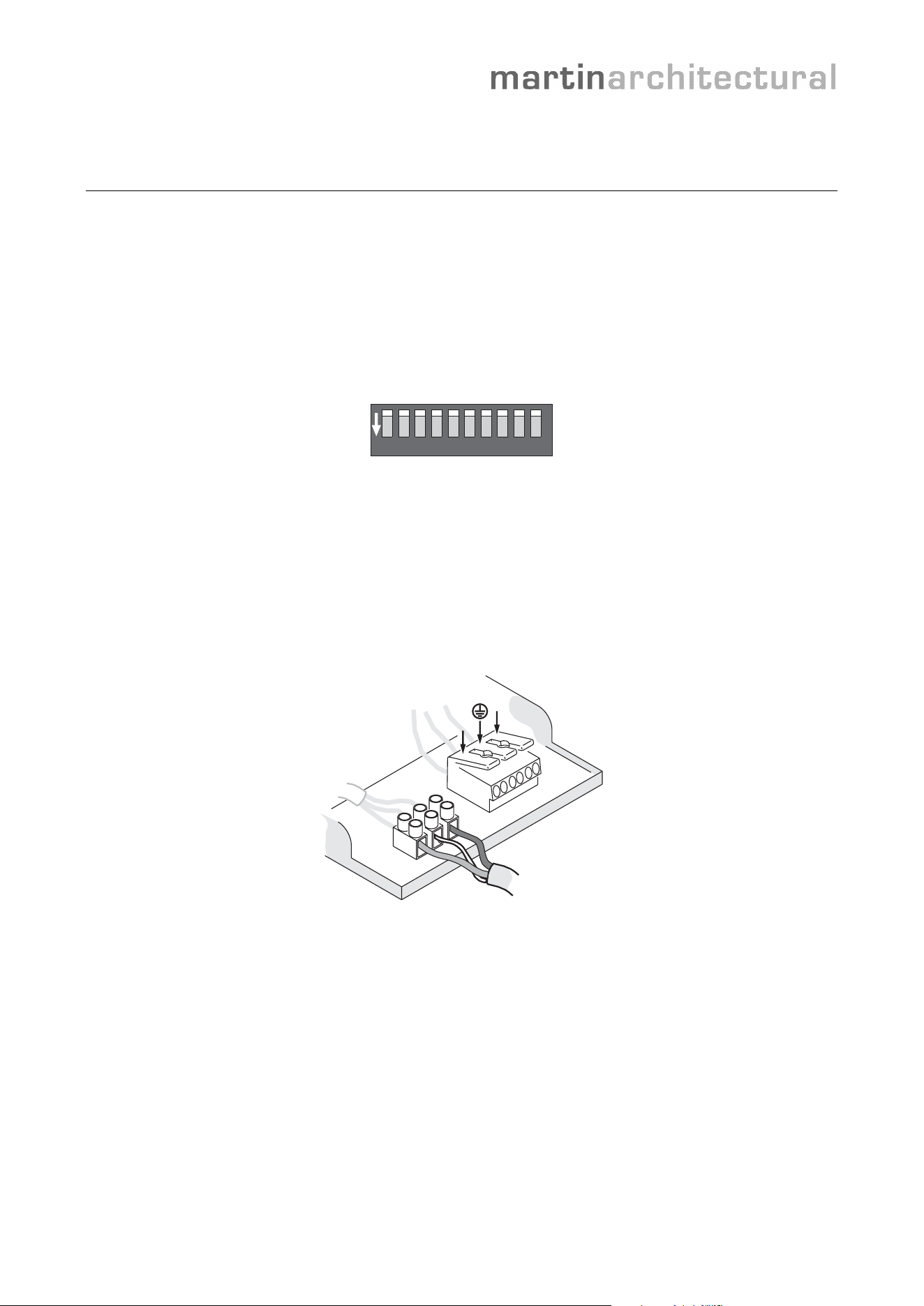
DMX stands for Digital MultipleX. In a multiplexed system, multiple devices are linked using only
one cable, but control commands can be sent to individual devices. In a DMX system, luminaires
are given their own “DMX address”, usually by setting the pins on a small DIP-switch inside the
luminaire. The DMX controller then sends control commands to that address.
1 2 3 4 5 6 7 8 9 10
ON
DIP-switch
Cabling
Standard Category 5 network cable that is suitable for RS-485 applications can be used for the
DMX link in a permanent installation. Three conductors are used for data hot (+), data cold (-) and
shield. The cable must be twisted-pair type, but can be shielded or unshielded. Terminal blocks or
RJ-45 connectors are commonly used for connections. A DMX signal is very robust, but as with
any digital network a minimum of precautions must be taken to avoid interference. For example,
running DMX and power cable side-by-side should be avoided.
N
L
DMX connections
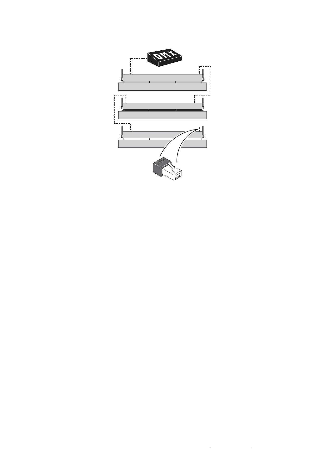
A DMX link is connected in a “daisy-chain”. In other words, a cable is run from the controller’s DMX
output connector to the first luminaire’s DMX input connector. Then a cable is run from the first
luminaire’s DMX output connector to the next luminaire’s input connector, and so on.
To split the link into branches, connect more than 32 luminaires, or exceed 500 meters, a splitter-
amplifier must be added to the link. At the end of the link, a 120 ohm resistor (or a DMX termination
plug containing this resistor) must be connected across the hot (+) and cold (-) DMX terminals to
‘soak up’ the signal.
Most splitter-amplifier devices are optically isolated. This means that they convert the electrical
signal to an optical signal and then back, providing a barrier against electrical faults and eliminating
problems that may result from differences in ground potential.
- 2 -
DMX link with RJ-45 termination plug
DMX in large installations
On a DMX link, 8-bit control commands can be sent on 512 separate channels. If more than 512
channels are needed, a separate link must be created. Each link with 512 channels is referred
to as a DMX universe.
To simplify cabling in large installations, Ethernet can be used to send control signals to multiple
DMX universes through a single cable. Ethernet-to-DMX breakout boxes closer to the
luminaires then convert the signals to DMX.
Wireless DMX can solve awkard cabling problems. Wireless DMX equipment generally uses
WLAN technology for wireless ‘bridges’ between cabled links.
Controlling via DMX
Intelligent luminaires normally use one DMX channel per effect. A Cyclo 04 luminaire with red.
green, blue and white fluorescent tubes will thus respond to dimming commands on four
channels, one for each tube.
If each luminaire has its own DMX address, it is possible to control luminaires individually.
However, in large installations, the operator will generally want to control multiple luminaires in
groups that behave identically. Two methods can be used to achieve this:
• If each luminaire has its own unique DMX address, the DMX controller can be set up to
send a command to more than one DMX address.
• If multiple luminaires are given the same DMX address, they will all respond to a
command sent to that address from the controller.

- 3 -
Frequently Asked Questions
Can DMX-controlled luminaires run without a DMX controller?
All Martin DMX luminaires can run stand-alone light shows that are programmed using the
onboard DIP-switch. Stand-alone light shows can also be synchronized, with one luminaire
acting as master and sending control signals to slave luminaires via the DMX link.
What is a DMX address?
A luminaire’s DMX address is the first of the channels it uses to receive data from the control
device. For example, a luminaire that has three fluorescent tubes uses three channels, one to
dim each tube. If you set it to DMX address 101, it will receive commands from the control
device on channels 101, 102 and 103. Channel 104 is then available for the next luminaire.
How do I set a DMX address on a DIP-switch?
DMX addresses are set on DIP-switches as binary numbers. If you are not comfortable
converting decimal to binary numbers, all Martin user manuals include conversion tables.
Alternatively, you can view or download a free DIP-switch calculator from the Martin website.
This little application converts decimal to binary numbers and displays a picture of exactly how
to set the pins on the DIP-switch for any address.
Some luminaires in my installation will not obey commands or are flickering. How do I
find the problem?
Flickering or unexpected behavior can be a sign of a fault in the DMX link. If only luminaires
after a certain point in the link are flickering, check the connections and cable to the first
luminaire with a problem.
To establish whether the cause of the problem is a faulty luminaire, bypass it by connecting the
DMX input and output cables directly together. If the other luminaires now work correctly, there
may be an internal fault in the luminaire you have bypassed.
Flickering can also occur if the shield in the DMX cable is allowed to come into contact with the
chassis of luminaires or other devices, creating an earth-loop.
How can I test the quality of the DMX signal?
Martin can supply a portable DMX testing device called ‘The Wife’ that analyzes every aspect of
the DMX signal and is extremely useful during troubleshooting.
How can I test the DMX cable in an installation?
You can carry out a simple cable test with an ohm meter. When the DMX link is correctly
terminated, the resistance across the hot (+) and cold (-) conductors at the controller end of
each DMX link should be between 90 and 120 ohms plus the resistance of the cable.
Resistance between hot (+) and shield or cold (-) and shield should be greater than 2 Kilo-
ohms. Resistance between any conductor and any connector shell should be several Mega-
ohms.
I have just completed a new installation, but some luminaires will not respond correctly
to DMX control. What could be wrong?
The most likely problem is that DMX addresses are set incorrectly on the luminaires or control
device. If addresses are correct, there may be a problem with the DMX cable or connections.
I know the DMX link must be a ‘daisy chain’ in one single line. Can I split it into a Y-
shape?
Yes, you can. All you need to do is add a splitter-amplifier at the point where you split the link.
The Martin OptoSplitter is suitable, and will allow you to split a DMX link into four branches.
- 4 -
What type of DMX controller do I need?
The type of controller required depends on a number of factors such as the size of your
installation, the level of skill of the person in charge of running the light show and the complexity
of the light shows you want to run. Obtain good specialist advice before you buy your controller.
What type of signal is DMX?
DMX voltage levels and cable practices are RS-485 standard, with a data rate of 250 kbps.
Can I use both DMX and analog 10 V control in the same luminaires?
No, this is not normally possible. Martin intelligent luminaires are generally sold in either DMX or
analog control versions.
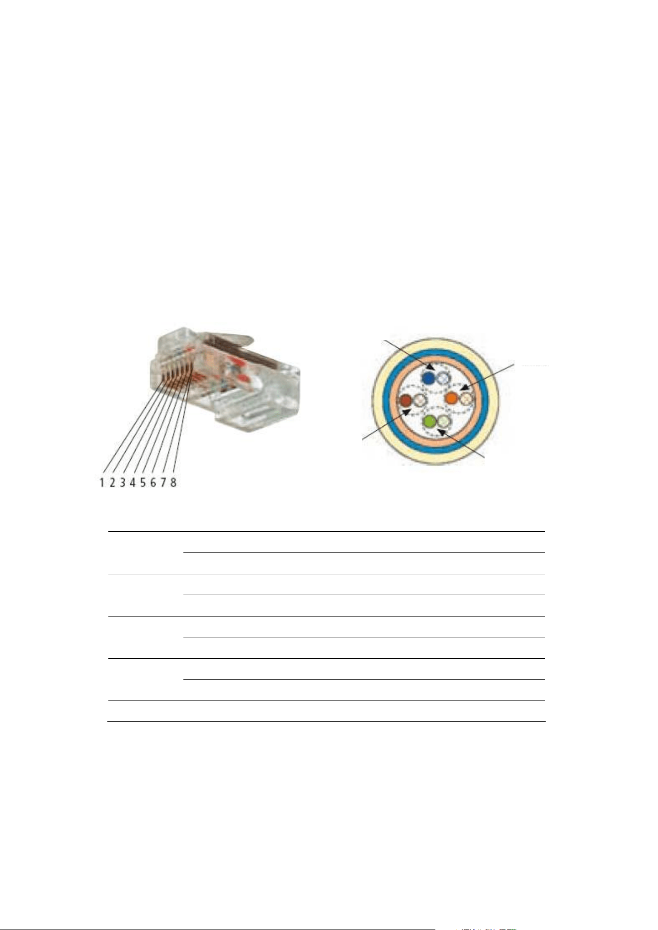
How are DMX connectors wired?
RJ-45 connectors used for DMX must have the following pinout:
Pair Wire/pin Wire color Purpose
1 White/orange Data 1 hot (+)
Pair 2
2 Orange Data 1 cold (-)
3 White/green Data 2 hot (+) see note below
Pair 3
6 Green Data 2 cold (-) see note below
4 Blue Not used
Pair 1
5 White/blue Not used
7 White/brown Data common
Pair 4
8 Brown Data common
Shield Drain
Note: Data 2 connections are not necessary for luminaires that conform to the DMX512/1990
standard. They are only required for luminaires that conform to the more recent DMX512-A
standard and that communicate extra data in connection with RDM (Remote Device
Management), for example.
Pair 4
Pair 1
Pair 2
Pair 3

- 5 -
3-pin and 5-pin XLR connectors are commonly used for DMX connections in entertainment
lighting but can also be found in architectural lighting equipment. XLR connectors are wired as
follows:
• Pin 1: data common/shield
• Pin 2: data cold (-)
• Pin 3: data hot (+)
Pin numbers are marked on XLR connectors but you often have to look carefully to find them.
Note that the common/shield conductor connected to pin 1 must not be allowed to come into
contact with the shell of an XLR connector or the chassis of a device, as this may cause a
ground loop that will disturb the signal.
Pins 4 and 5 on 5-pin XLR connectors are not normally used, but pin 4 is available for Data 2
cold (-) and pin 5 for Data 2 hot (+).
