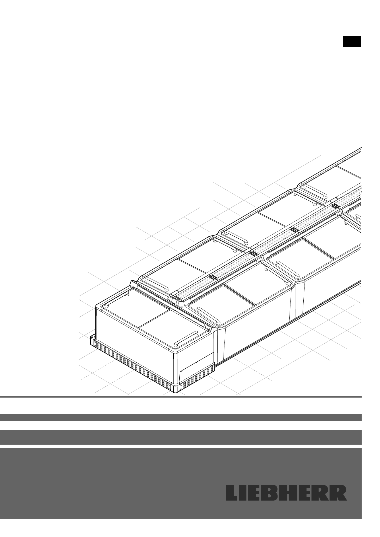
Assembly instructions
EN
ST 11/SGT 11
ST 13/SGT 13
STE 11
7084 183-00

2
EN
Content
Safety instructions and warnings ................................... 2
Appliance dimensions .................................................... 3
Cable lengths .................................................................. 3
Requirements for assembly ........................................... 4
Requirements for the place of installation ........................... 4
Requirements for the electrical connection ........................ 4
Requirements for a remote data transmission connection .. 4
Bus connection ............................................................... 4
Addressing...................................................................... 5
Scope of delivery ........................................................... 6
Standard (per appliance).................................................... 6
Accessories (depending on conguration) ......................... 6
Accessories (optional) ........................................................ 6
Positioning rail................................................................. 6
Single-piece block end plate ........................................... 6
Split block end plate........................................................ 6
End-of-aisle appliance connection kit ............................. 6
Cover .............................................................................. 6
End-of-aisle appliance collision guard ............................ 7
Block end plate collision guard ....................................... 7
Product plate holder (for longitudinal appliances) ........... 7
Product plate holder (for end-of-aisle appliances) .......... 7
Plug set for alarm output ................................................. 7
Transport and unpacking ............................................... 7
Moving the appliances to the place of installation .............. 7
Possible congurations .................................................. 8
Installing an individual appliance ........................................ 8
Installing appliances in a row .............................................. 8
Installing the appliances in a block or in island form ........... 9
Axing shaped foam tape ................................................ 10
Installation and connection .......................................... 10
Fitting the cables .............................................................. 10
Fitting the service interface extension ........................... 12
External alarm (oating alarm output) ........................... 13
Connecting appliances ..................................................... 14
End-of-aisle appliance connection kit ............................... 14
Block completion with block end plates ............................ 16
Single-piece block end plate ......................................... 16
Split block end plates .................................................... 16
Fitting the protection strips ............................................... 17
Individual appliances .................................................... 17
Row conguration ......................................................... 17
Block conguration ....................................................... 18
Fitting the cover ................................................................ 18
Assembling the cover ................................................... 18
Inserting the covers....................................................... 19
Assigning addresses to the appliances ............................ 19
Commissioning the appliances ........................................ 20
Checks ......................................................................... 20
Fitting various accessories ........................................... 21
Fitting product plate holders ............................................. 21
Product plate holders for longitudinal appliances .......... 21
Product plate holders for end-of-aisle appliances ......... 21
Fitting the collision guard .................................................. 22
Block completion with end-of-aisle appliance ............... 22
Block completion with a block end plate ....................... 23
Technical data .............................................................. 25
Safety instructions and warnings
• If there is obvious transport damage on
the appliance after it has been unpacked,
contact the supplier. Do not start the
appliance.
• Do not allow naked ames or ignition sources
to enter the appliance. When transporting
and cleaning the appliance, ensure that the
refrigerant circuit is not damaged. In the
event of damage, make sure that there are no
ignition sources nearby and keep the room
well ventilated.
• Do not place objects on the appliance and
do not place heavy loads on the sliding glass
lids. The lids could be damaged.
3
EN
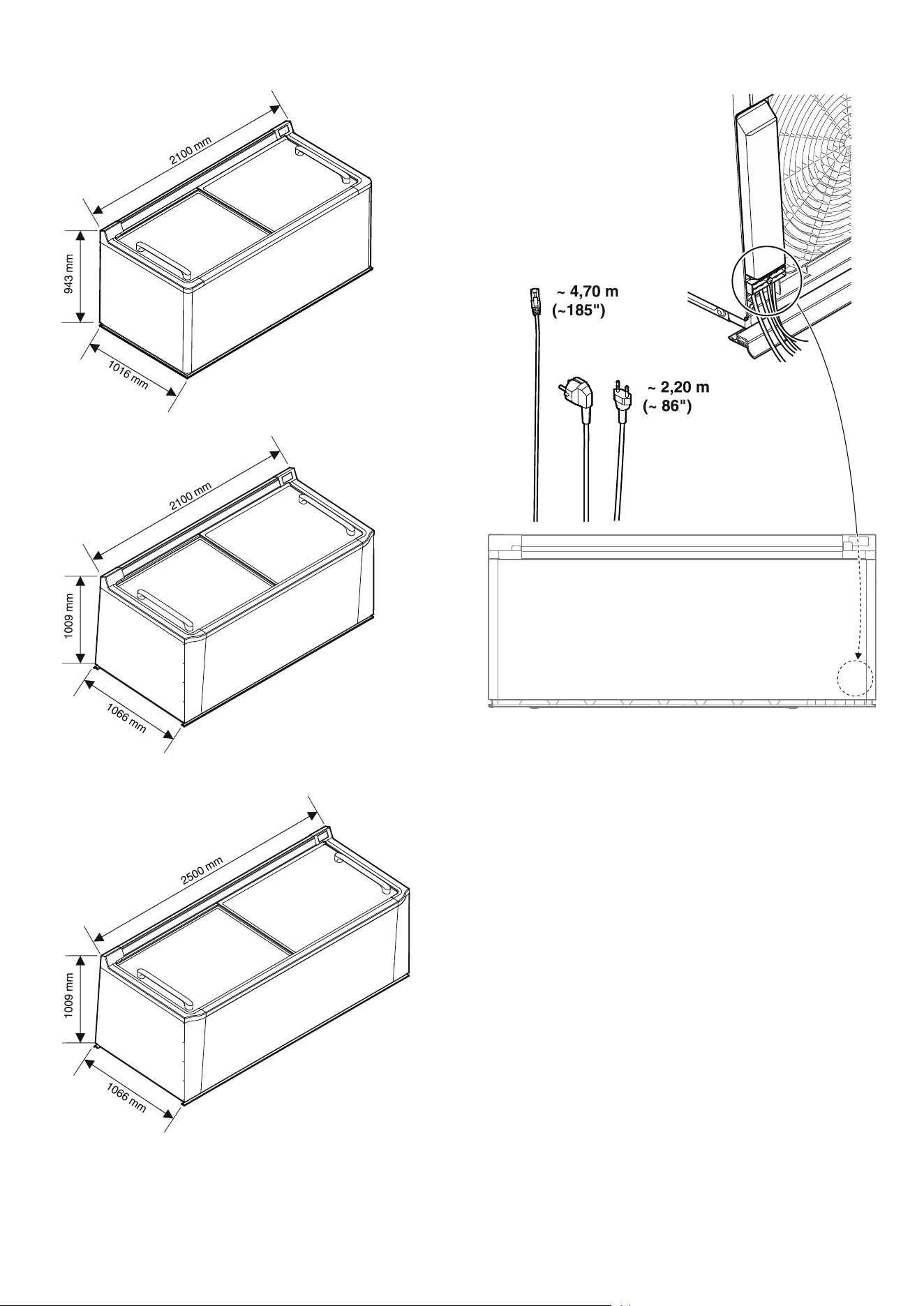
Appliance dimensions
STE 11
ST 11/SGT 11
ST 13/SGT 13
Cable lengths
Free cable lengths from strain relief device outlet.

4
EN
Requirements for assembly
The assembly must comply with the applicable regulations,
standards, directives and laws where they apply to the subject
of the contract.
Work on the electrical system (electrical connection, cable duct
or sockets) may only be carried out by a qualied electrician.
Note
To avoid the assembly work being delayed or even stopped, the
installation of the appliances should be carefully planned in ad-
vance. It must be ensured that all the requirements are satised.
Requirements for the place of installation
Ensure that the place of installation for assembling the appli-
ances is suitable and properly prepared.
– Any existing old appliances must be removed and disposed
of in an environmentally friendly manner.
– The place of installation must be free of dirt and moisture.
– The evenness of the oor surface must comply with the
usual limit values for evenness deviations set out in DIN
18202.
– The ambient temperature must correspond to the climate
rating. The climate rating applicable to your appliance is
shown in the operating instructions.
– Any display unit above the appliance must be straight and
perpendicular, and must not contain any goods.
– Any positioning rails must be installed to meet the plinth foot
spacings of the appliances.
– If a collision guard or positioning rails (accessories) are
installed, approval must be obtained from a qualied body
to drill holes in the oor. It must be ensured that no cables or
pipes (e.g. underoor heating) in the oor are damaged.
Ventilation
Ensure that the following cross-sections for ventilating the
appliances are maintained in the supply air area on the rear of
the appliance:
– 1.8m: > 550cm²
– 2.1m: > 600cm²
– 2.5m: > 700cm²
If ram protection is installed, the same cross sections must be
ensured for the exhaust air.
In combination with surface-mounted appliances with
downward-directed exhaust air (heat), appropriate partitioning
must be provided against this.
Requirements for the electrical connection
– We recommend that separate circuits are installed for the
lighting and chest refrigeration units. The sockets must be
clearly distinguishable.
– Two sockets must be prepared for each appliance for these
two circuits. The sockets must be permanently xed and
clearly labelled.
– Each appliance must be protected by its own fuse.
– A separate fuse must be provided for the lighting
IMPORTANT
Do not connect the appliance
using an extension cable or
extension socket.
Requirements for a remote data transmission
connection
– A connection from the appliance blocks to the gateway
location must be established on site using suitable sockets
and cables (CAT5 or higher) with a bus topology.
– The appliances are networked using one or more coupling
modules depending on the system environment, see "Bus
connection", page 4.
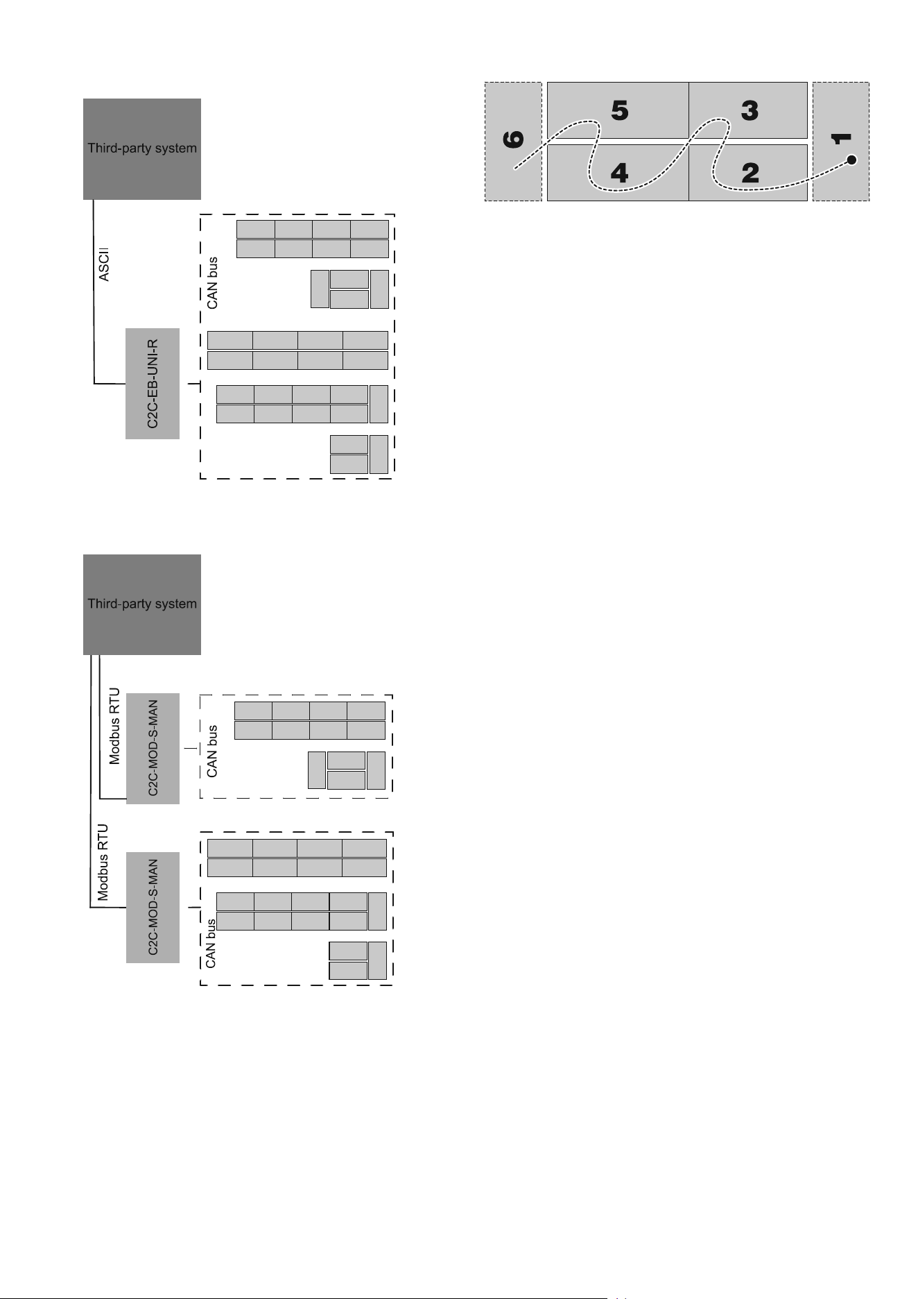
Bus connection
Up to 120 appliances can be networked and integrated into the
in-house system using one or more coupling modules.
Note
The alarm priority with CAN connectivity is limited as standard
to a maximum of 2 when the appliance is delivered. This means
that the forwarding of the alarm is restricted when the shop is
closed. The setting can be changed if necessary by the gateway
manufacturer. The list of alarm scenarios is included in the ser-
vice documentation.
A coupling module is required for transmitting the CAN bus
protocol.
Depending on the system environment and the number of ap-
pliances, we recommend that you use the following coupling
modules (made by Wurm):
5
EN
– C2C-EB-UNI-R
ASCII protocol
1 coupling module for an arbitrary number of appliances
– C2C-MOD-S-MAN
RS485 standard interface (Modbus RTU) slave
with 1 coupling module for up to 20 appliances
Each appliance has two CAN bus ports for networking the appli-
ances, see "Fitting the cables", page 10.
Addressing
Free addresses from the in-house system must be used to ad-
dress the bus with one- to three-gure numbers (1-999) being
allocated for this purpose.
The addresses are entered individually on each appliance, see
"Assigning addresses to the appliances", page 19.
6
EN
Scope of delivery
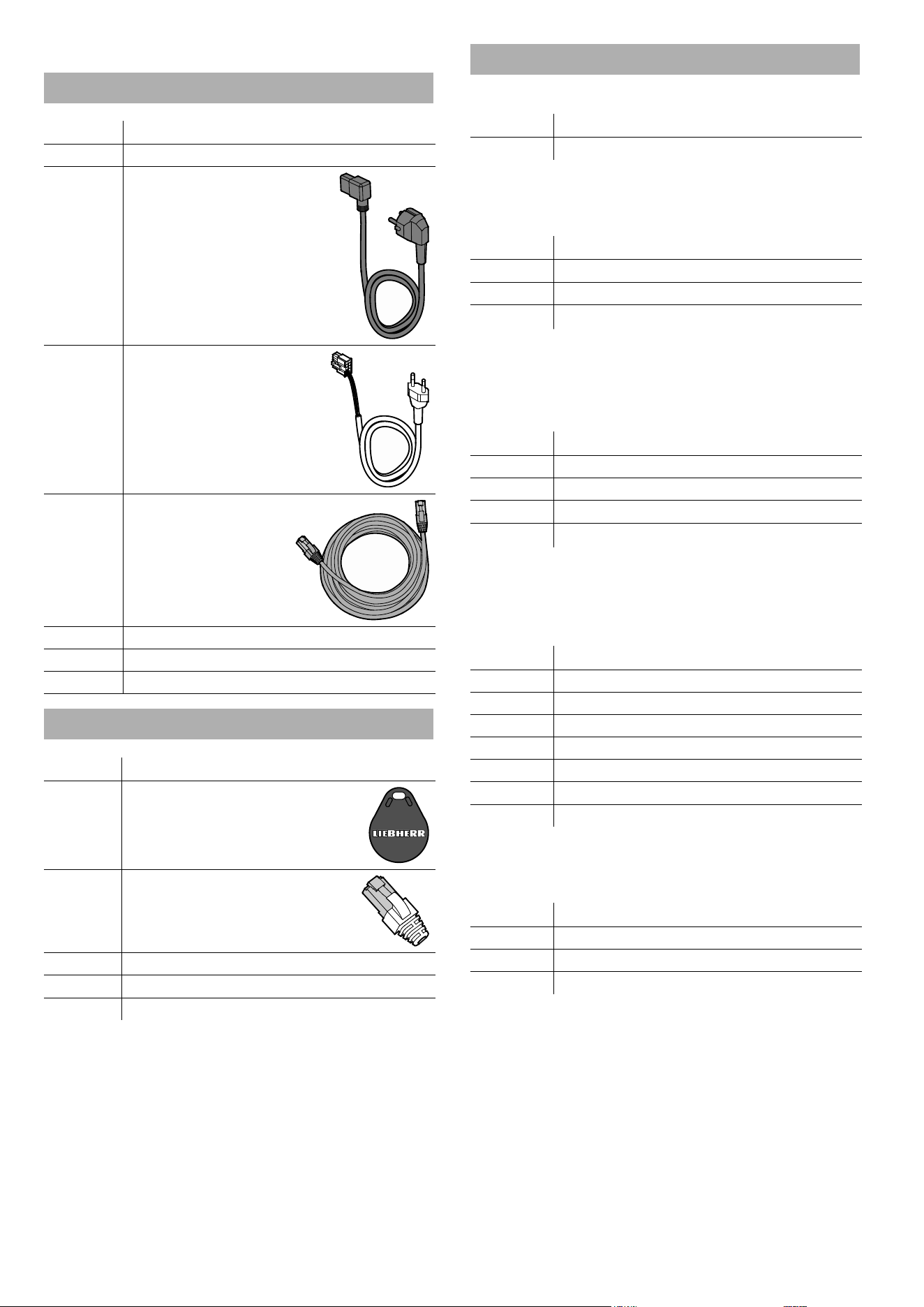
Standard (per appliance)
Quantity Description
1 Appliance
1
Power connection cable
(2.50 m)
1
Light cable for manual
control (2.50 m)
1 Network cable (5 m)
1 Ice scraper
1 Service type plate
1 Operating instructions
Accessories (depending on conguration)
Quantity Description
* RFID chip
* Terminating resistor
* Service interface extension (2 m)
* Protection strip
* Shaped foam tape
*) depending on conguration
Accessories (optional)
Positioning rail
Quantity Description
* Positioning rail (1.75 m)
*) depending on conguration
Single-piece block end plate
Quantity Description
* Block end plate
10** Screws
2** Protection strip corner pieces
*) depending on conguration
**) per plate
Split block end plate
Quantity* Description
1 Block end plate, left
1 Block end plate, right
12** Screws
2** Protection strip corner pieces
*) depending on conguration
**) per set
End-of-aisle appliance connection kit
Quantity* Description
2 Side pieces
1 Connection piece, right
1 Connection piece, left
1 Cover
9 Assembly bolts
1 Positioning bracket
2 Protection strip corner pieces
*) per set/end-of-aisle appliance
Cover
Quantity* Description
2** Perforated metal plate
4** Prole strips
4** Cover pieces
*) depending on conguration
**) per appliance
7
EN
End-of-aisle appliance collision guard
Quantity* Description
1 Front piece
1 Longitudinal side, right
1 Longitudinal side, left
2 Corner pieces
8 Cheese-head screws
12 Protective stoppers
4 Anchor bolts
*) per set/end-of-aisle appliance
Block end plate collision guard
Quantity* Description
1 Front piece
1 Corner piece, right
1 Corner piece, left
4 Cheese-head screws
8 Protective stoppers
4 Anchor bolts
*) per set
Product plate holder (for longitudinal appliances)
Quantity* Description
6 Retaining parts (angled)
6 Wing nuts
*) per appliance
Product plate holder (for end-of-aisle appliances)
Quantity* Description
3 Retaining parts (straight)
3 Wing nuts
*) per end-of-aisle appliance
Plug set for alarm output
Quantity Description
1 10-pin plug
6 Crimp contacts
Transport and unpacking
The appliance is supplied fully assembled standing on a pallet.
Check the appliance for transport damage before and while
unpacking it. Report any damage (loose parts, dents, scratches,
visible uid leaks, etc.) without delay.
Remove the packaging and check that the delivery is complete.
Ensure that the appliance is not damaged while it is being trans-
ported and unpacked.
WARNING
Danger of suocation due to packing
material and plastic lm!
Do not allow children to play with
packaging material.
Dispose of the packaging material in
compliance with current regulations.
Moving the appliances to the place of
installation
Wear safety shoes!
Wear gloves!
Move the appliances to the place of installation on the pallets
using suitable equipment.
Important
Ensure that the appliances are not damaged while they are be-
ing transported and unpacked.
Position the appliances in a line in the required conguration. If
an end-of-aisle appliance is included in the conguration, start
with this.
If the appliances are to be installed in a block, arrange them in
parallel.
Lifting the appliances o the pallet
At least two people are required for this.
Lift the appliances o the pallets using suitable equipment and
carefully lower them into position.
Leave enough space to the display unit above the appliances (if
there is one) and between them so that subsequent work can
be carried out with plenty of space. Do not push the appliances
together until later.
8
EN
Possible congurations
Note
The "Requirements for the place of installation", page 4 and
the "Requirements for the electrical connection", page 4,
must be complied with for all congurations.
If the appliances are networked, the "Requirements for a remote
data transmission connection", page 4 must also be com-
plied with.
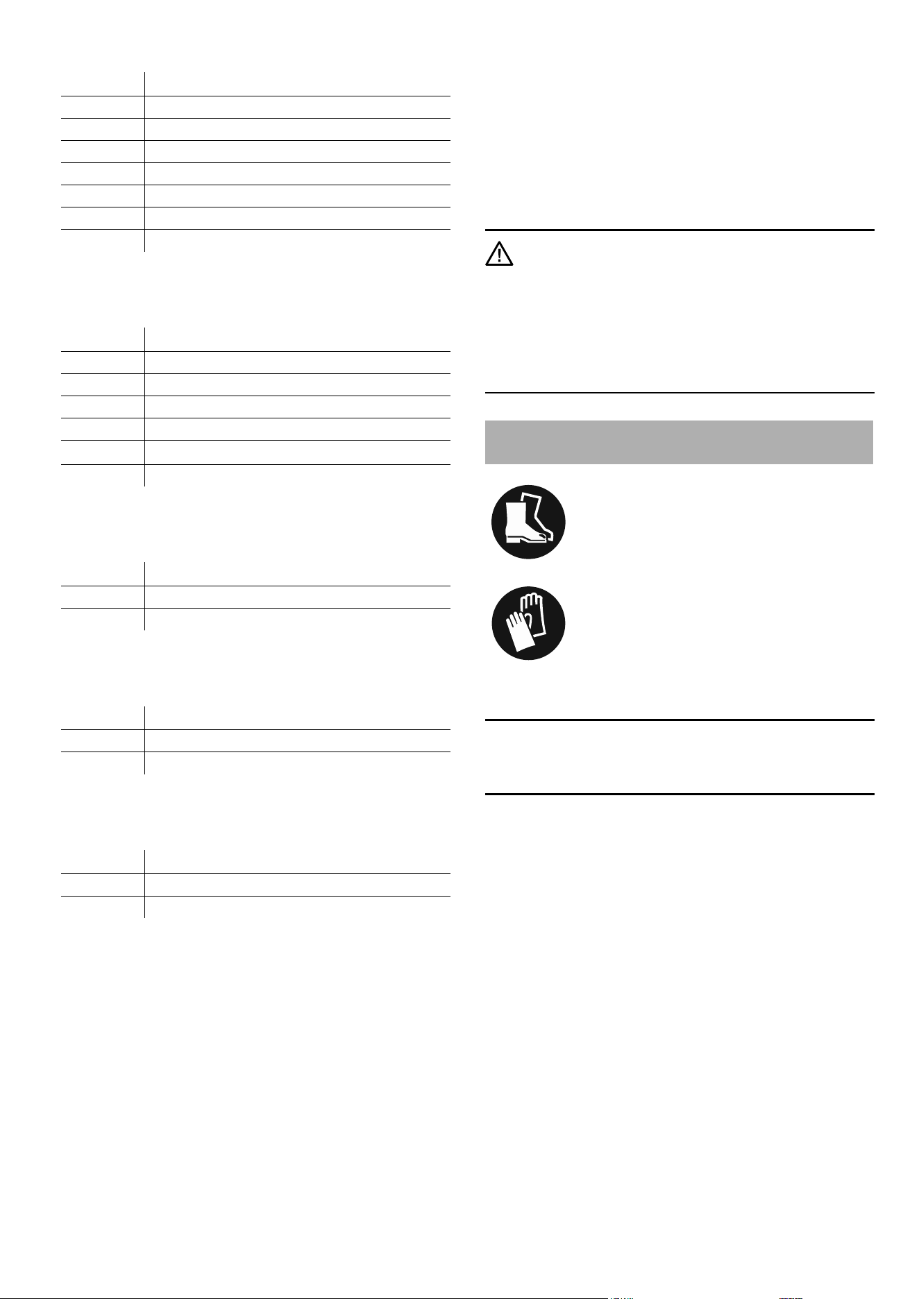
Installing an individual appliance
Every model can be installed individually.
1. "Fitting the cables", page 10
2. Positioning the appliance
Position the appliance at a distance measured on the oor of
at least 5 cm (1.97") from the rear limit surface (e.g. the wall).
Important
The air circulation must not be hindered.
3. "Connecting appliances", page 14
4. "Fitting the protection strips", page 17
5. "Commissioning the appliances", page 20
Installing appliances in a row
1. "Fitting the cables", page 10
2. "Axing shaped foam tape", page 10
3. Positioning the appliances
Position the appliances side by side at a distance measured
on the oor of at least 5 cm (1.97") from the rear limit surface
(e.g. the wall) and push them together without leaving a gap
between them.
Important
When pushing the appliances, it is vital that you ensure that
no cables are jammed or damaged.
Important
The air circulation must not be hindered.
4. "Connecting appliances", page 14
5. "Fitting the protection strips", page 17
6. "Assigning addresses to the appliances", page 19
7. "Commissioning the appliances", page 20
9
EN
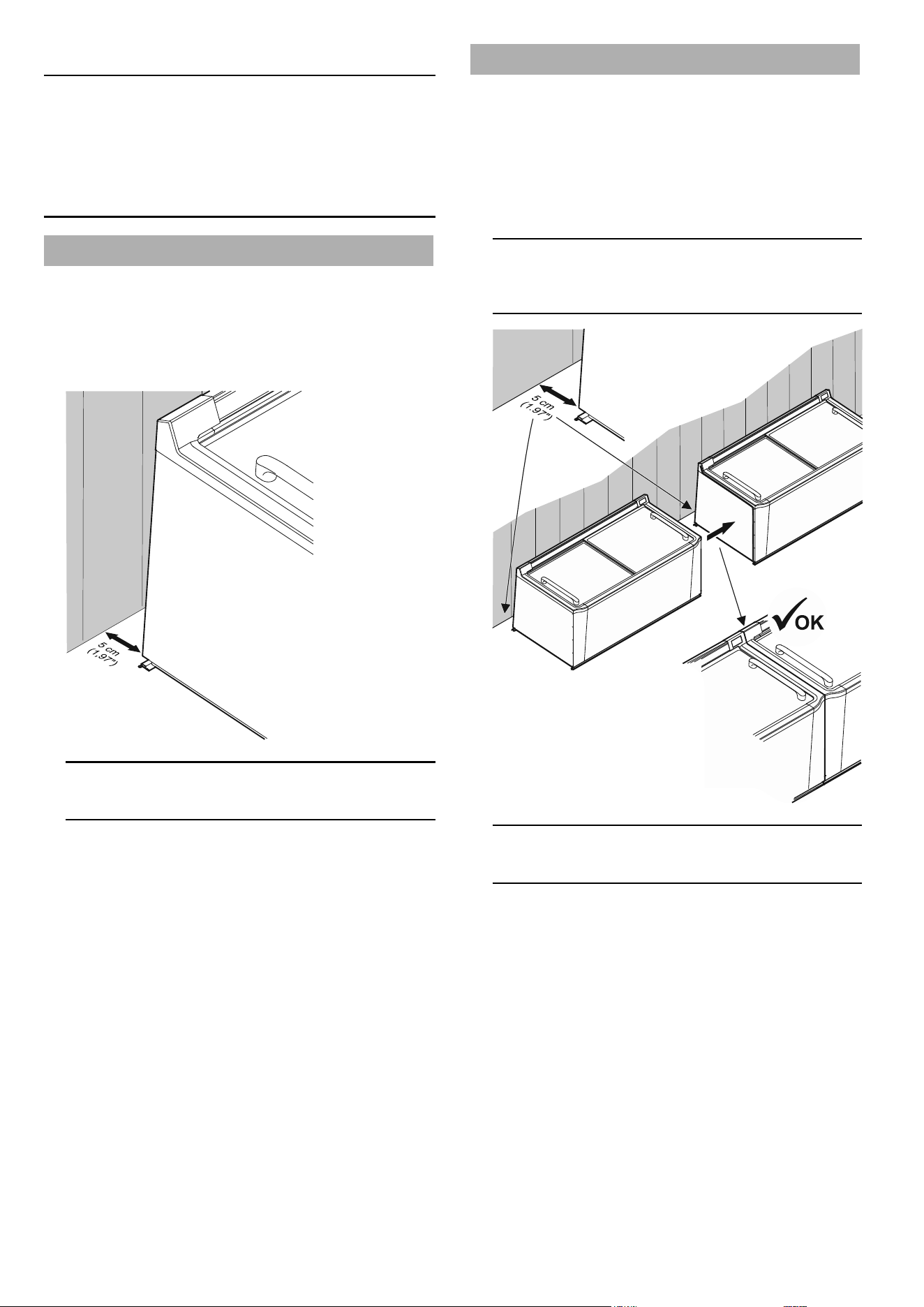
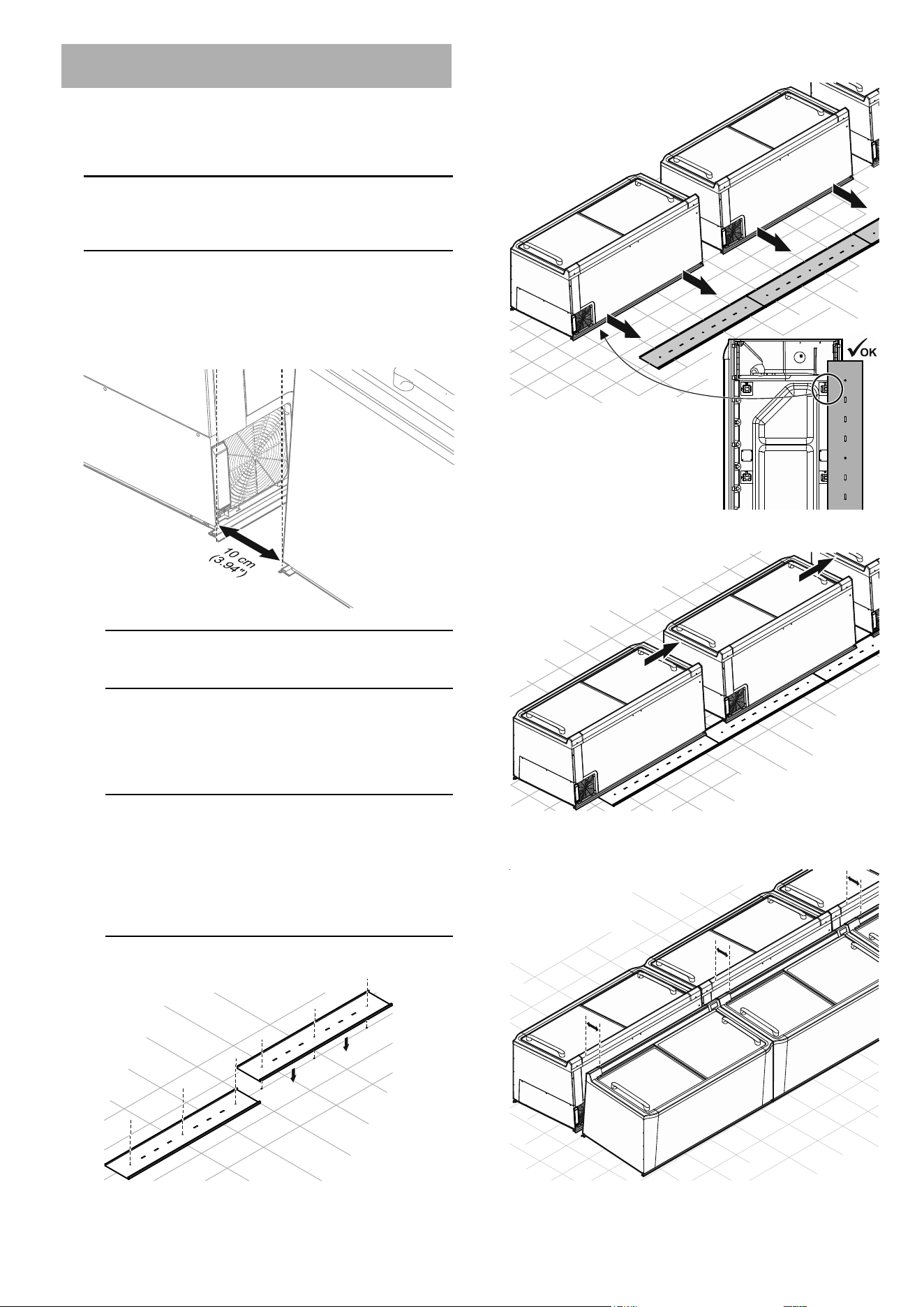
Installing the appliances in a block or in island
form
1. "Fitting the cables", page 10
2. "Axing shaped foam tape", page 10
3. Positioning the appliances
Important
When pushing the appliances, it is vital that you ensure that
no cables are jammed or damaged.
A) Without positioning rails
Place the appliances in the row in a straight line. Arrange
the opposite row parallel to the rst one.
The distance between the rows must be at least 10 cm
(3.94") (measured at the bottom appliance edges).
Important
The air circulation must not be hindered.
B) With positioning rails
Install the positioning rails in a straight line the length of
the block. The start and end may at most be ush with
the rst or last appliance.
Important
Approval must be obtained from a qualied body to drill
holes in the oor. It must be ensured that no cables or
pipes (e.g. underoor heating) in the oor are damaged.
The fastening material (screws, plugs and adhesive
tape) is not supplied and must be selected to suit the site
conditions.
Fix the positioning rails to the oor.
Position the appliances so that the rear feet touch the posi-
tioning rails.
Push the appliances together with no gaps between them.
Install the opposite row in the same way ensuring that the
appliances are parallel to each other.
10
EN
4. "Connecting appliances", page 14
5. Completing the end of the block:
"End-of-aisle appliance connection kit", page 14
or
"Block completion with block end plates", page 16
6. "Fitting the protection strips", page 17
7. "Fitting the cover", page 18
8. "Assigning addresses to the appliances", page 19
9. "Commissioning the appliances", page 20
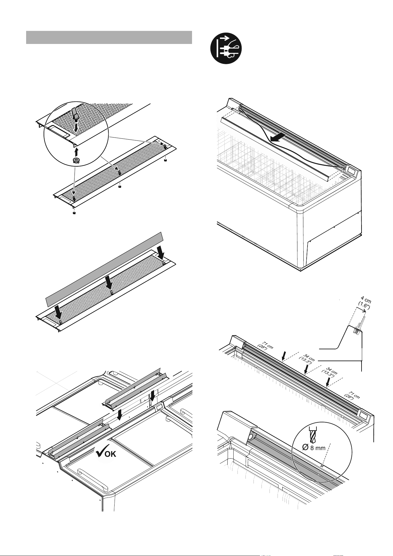
Axing shaped foam tape
Ax the shaped foam tape to the top and front sides of the
appliances to keep the impact areas of appliances in rows or
blocks free of dirt. This allows the appliances to be placed next
to each other without gaps in between and also compensates
for minor unevenness.
Note
Do not ax shaped foam tape to the outer side panels of the
rst and last appliance in the row.
Installation and connection
Fitting the cables
The cable connections are on the rear of the appliance under a
cover.
Important
The cables must be routed so that each appliance, including
those in rows or blocks, can be pulled out individually without
any problems for repair or service purposes.
Cables must not be jammed or damaged by this. Use any avail-
able cable suspension points.
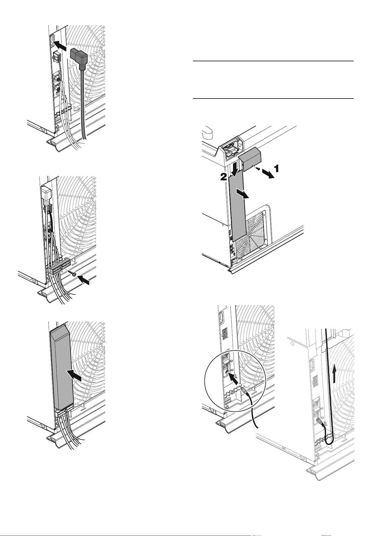
1. Remove cover.
2. Undo the screw and remove it together with the strain
relief device.
11
EN
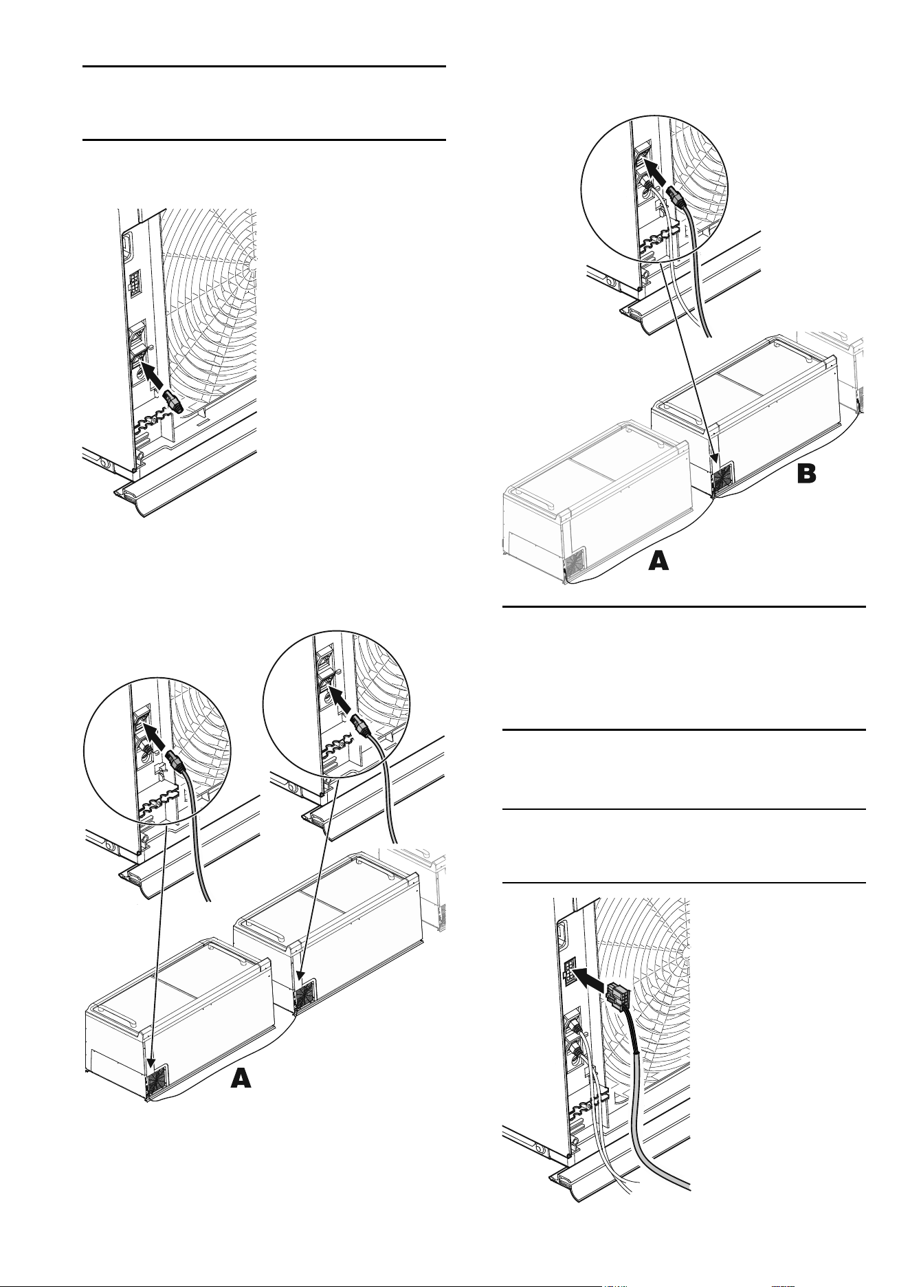
3. Connect the network cable
Note
The ports (input/output) may be freely selected. The connec-
tors must engage with an audible click.
First appliance
– Connect the terminating resistor.
Additional appliances
– Connect one plug of the network cable (A).
– Connect the other plug of the network cable (A) to the
next appliance.
– To connect additional appliances, connect the plug of
another network cable (B) to the second appliance and
then connect it to the next appliance. Continue until all
the appliances are connected.
Note
The empty port on the last appliance in a conguration is
used for connection to the coupling module and then to the
in-house LAN.
Both bus ports must therefore be occupied on every appli-
ance.
4. Connect the light cable plug.
See also "External alarm (oating alarm output)",
page 13.
Note
This plug does not need to be connected if the lighting is
controlled via the network.
12
EN
5. Connect the power connection cable plug.
6. Fit the strain relief device , placing the cables in it.
Insert screw.
7. Fit the cover.
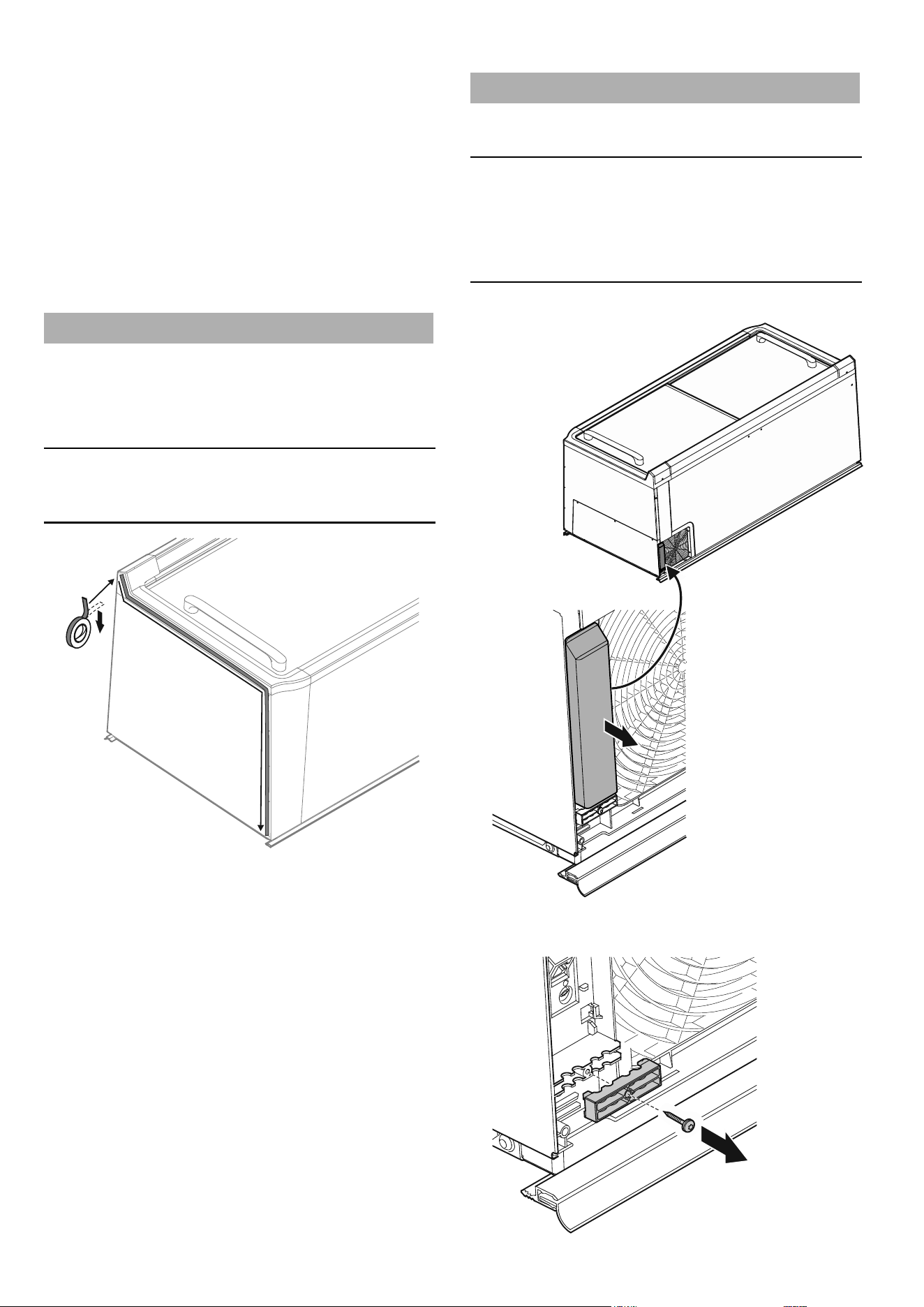
Fitting the service interface extension
The service interface is required to connect the test tool and
for service work. It is on the rear of the appliances. To provide
easier access, an extension can be tted to a dened appliance
(with easy access, e.g. the rst appliance in the row).
Note
We recommend that the appliance with the extension is marked
or documented to speed things up when service work is re-
quired.
1. Undo the screw and take o the operating panel cover.
2. Slide the cable duct cover downwards and remove it.
3. Connect the pawl plug, thread the cable through the
strain relief device and then route it upwards through
the left-hand cable duct.
13
EN
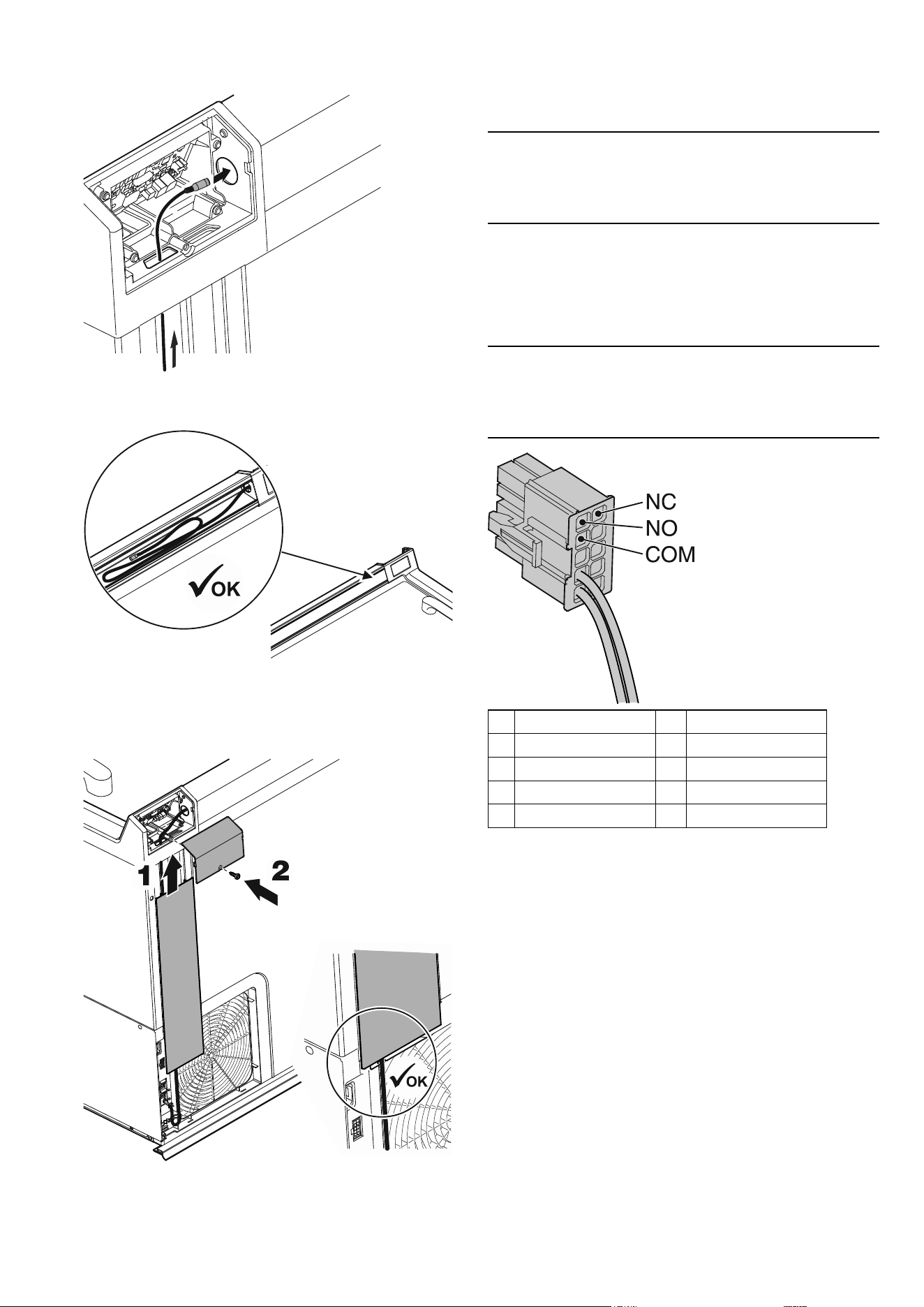
4. Route the service interface through the opening from
below into the operating panel housing and then
through the right-hand housing opening.
5. Push in the remainder of the cable and place it behind
the price label strip.
6. Fit the cable duct cover ensuring that the cable is in
the guide below the cover.
7. Fit the operating panel cover and secure it with the
screw.
External alarm (oating alarm output)
It is possible to connect the appliance to an external alarm
device.
Crimp contacts can be added to the light cable for this purpose.
Note
If there is no light cable (e.g. if the lighting is controlled via the
network), a plug with crimp contacts is available separately, see
"Accessories (optional)", page 6.
The contacts (NC, NO and COM) can be used to connect the
appliance to an optical or acoustic alarm device.
The connector is designed for a maximum of 230 V AC/0 A
or 24 V DC/5 A from a SELV (safety extra-low voltage) source
(minimum current 150 mA).
Important
When supplying mains voltage to the oating alarm contact, the
technical safety requirements of standard EN 60335 will not be
satised.
1
NO
6
NC
2
COM
7
free
3
free
8
free
4
Light IN (bn)
9
DIGITAL IN 230 VAC
5
Light IN (bu)
10
DIGITAL IN (neutral)
NC operating light
Connection for a control lamp to indicate that the appliance is in
normal mode.
COM external power supply unit
Maximum 230 V AC/10 A or 24 V DC/5 A
Minimum current 150 mA
NO alarm output
Connection for a visual warning light or an acoustic alarm signal.
14
EN
Connecting appliances
If separate circuits are used for lighting and cooling, the relevant
sockets must be clearly labelled.
1. Plug the mains plug of the power connection cable into
the appropriate socket.
2. Plug the mains plug of the light cable into the
appropriate socket.
WARNING
If the mains plug of an appliance is
accidentally placed into a lighting socket,
when the circuit for the lighting is switched
o (e.g. at night), the cooling function will
no longer work and the food inside the
appliance will be spoiled.
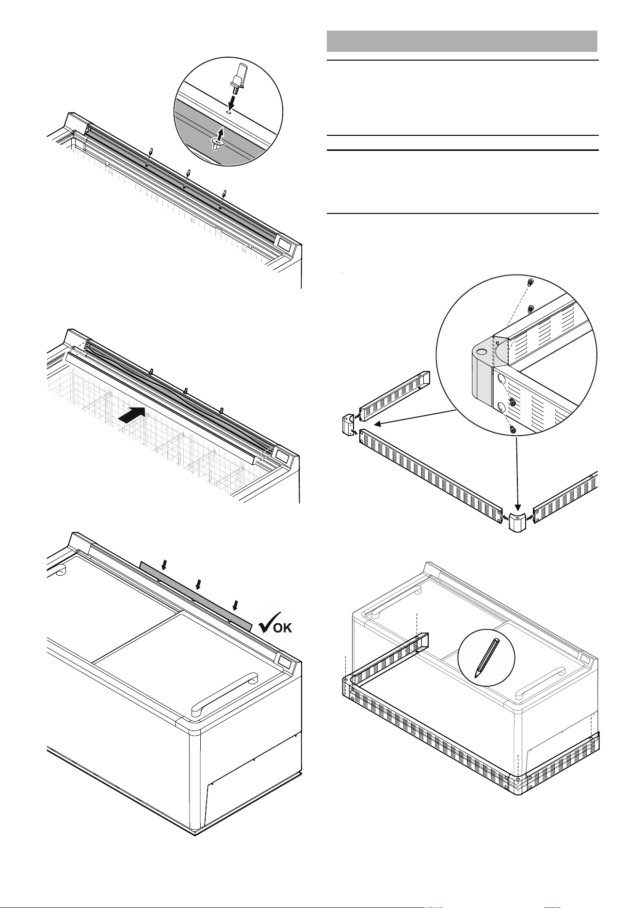
End-of-aisle appliance connection kit
To achieve an attractive connection of the end-of-aisle appli-
ance to the block of appliances, t the parts of the "End-of-aisle
appliance connection kit" which is available as an accessory.
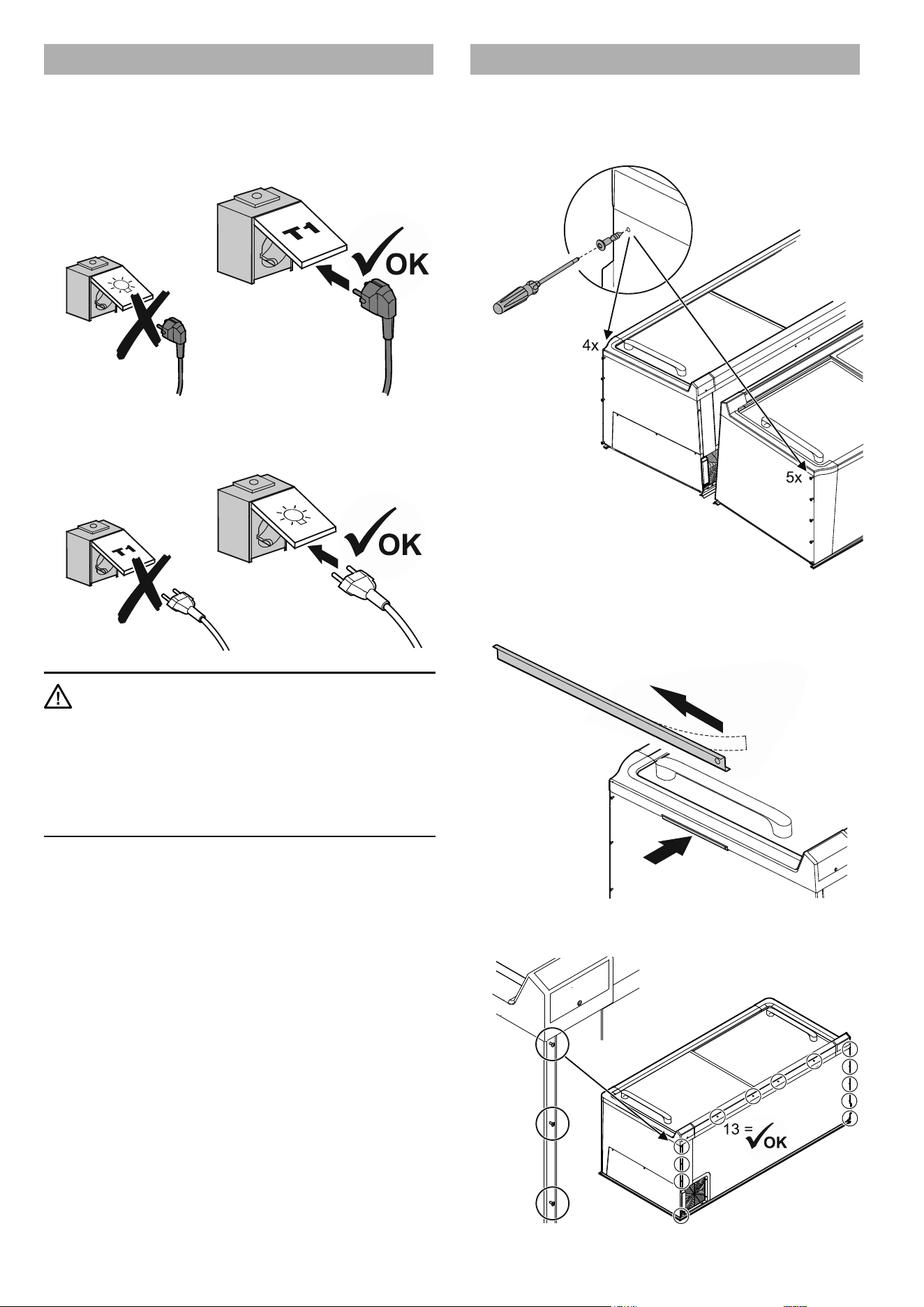
1. Screw 9 assembly bolts into the block end appliances.
2. Remove the backing lm and ax the positioning
brackets on the left-hand block end appliance as
shown.
3. Check: 13 assembly bolts are pre-assembled on the
rear of the end-of-aisle appliance.
15
EN
4. Fit the protection strip to the rear of the end-of-
aisle appliance, see "Fitting the protection strips",
page 17.
5. If necessary, t product plate holders (available as
accessories), see "Product plate holders for end-of-
aisle appliances", page 21.
6. Push the end-of-aisle appliance up to 10 cm (3.94")
against the block end appliances.
7. Fit the end-of-aisle appliance connection kit.
Attach the side pieces to the assembly bolts on the block
end appliances and on the end-of-aisle appliance, then
press them downwards.
Insert the left-hand connection piece and attach it to the
assembly bolts, slide it to the right and push the pins into the
side pieces.
Insert the right-hand connection piece and connect it to
the left-hand connection piece, then attach it to the assem-
bly bolts, slide it to the left and push the pins into the side
pieces.
Fit the cover.
16
EN
Block completion with block end plates
– Ax shaped foam tape to the block end appliances, see
"Axing shaped foam tape", page 10.
– Check the alignment and spacing:
Hold the block end plate to the block end and align it
with the edges of the appliances. Move the appliances if
necessary.
Single-piece block end plate
If there is a display unit above the appliance, no posts may pro-
ject over the end of the block.
1. Secure the block end plate with 10 screws.
Split block end plates
The block end plates can be placed ush with the cable ducts
(for power supply from above) or posts for a display unit above
the appliances measuring 8 cm (3.15") in width.
If the posts are wider, the block end plates must be cut to size
before being tted.
1. Secure the left and right block end plates with 6 screws
each.
17
EN
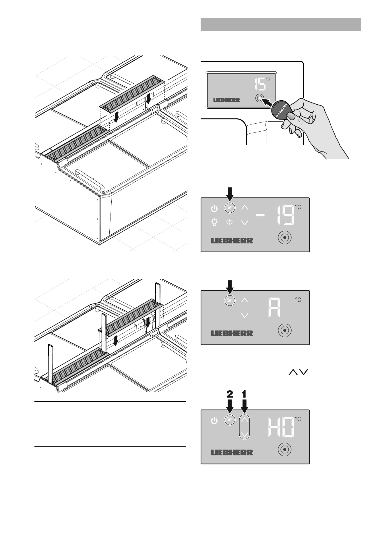
Fitting the protection strips
Individual appliances
End-of-aisle appliance (STE 11)
– Press the protection strip into the prole strip on the rear
of the end-of-aisle appliance and insert it along its length,
sliding it inward around 2 - 3 cm at the edges.
– Fit the protection strip corner pieces to the front of the
appliance.
– Press in and insert the protection strip into the prole strips
on the sides and front.
Longitudinal appliances (ST 11/SGT 11, ST 13/SGT 13)
– Press the protection strip into the prole strip on the front of
the appliance and insert it along its whole length.
Row conguration
– Press the protection strip into the prole strip on the front of
the rst appliance and insert it along the whole length of the
row.
18
EN
Block conguration
1. Fitting the protection strip corner pieces
A) Fitting the protection strip corner pieces on the
end-of-aisle appliance
See "Fitting the protection strips", page 17
B) Fitting the protection strip corner pieces on the
block ends
2. Fitting the protection strip around the block
– Press the protection strip into the prole strips on the
block end plates and the fronts of the appliances and
insert it all around the block of appliances.
Fitting the cover
Assembling the cover
1. Fit the prole strips to the longitudinal sides of the
perforated metal plate.
2. Fit the cover pieces to the narrow sides of the
perforated metal plate.
Note
The cover pieces have a dierent cut-out pattern to match
the posts for congurations with a display unit above the
appliances.
Examples of cover pieces with cut-outs:
19
EN
Inserting the covers
A) Conguration without a display unit above the
appliances
Fit the covers in sequence.
B) Conguration with a display unit above the appliances
Fit the covers in sequence ensuring that the cut-outs match.
Note
Gaps which may be created at the block ends between the
covers and the end-of-aisle appliances or the block end
plates can be closed using a cover cut to the appropriate
length.
Assigning addresses to the appliances
Enter the address (see "Addressing", page 5) on each appli-
ance individually.
– Touch the activation point on the display with the RFID chip.
The control menu will appear:
– Press Set for approx. 5 seconds.
Menu A for entering the address will appear:
– Press Set briey.
Menu H for entering the hundreds gure will appear; the rel-
evant number will ash:
– Select the required value using
.
– Press Set briey to conrm.
20
EN
Menu C for entering the tens gure will appear; the relevant
number will ash:
– Select the required value using
.
– Press Set briey to conrm.
Menu E for entering the units gure will appear; the relevant
number will ash:
– Select the required value using
.
– Press Set briey to conrm.
The idle screen will appear:
Note
We recommend that the address of each appliance is noted or
documented (e.g. an adhesive label on the rear of the appli-
ance) to speed things up for service work.
Commissioning the appliances
Checks
– Test the lighting connections (if the circuits are separate):
Remove the light fuses – all the appliances must be unlit. If
this is not the case, the plugs on the appliances which are lit
have been inserted in the wrong sockets, see "Connecting
appliances", page 14.
– Check the appliance for correct functioning and correct
temperature setting:
Test the various appliances to ensure that they function
perfectly.
If any defects which cannot be rectied are found, please
notify our customer service department.
– Check the addresses:
Check the settings of the appliances using the test tool.
Note
Remove the dirt caused by the installation, following the
information in the section entitled "Cleaning" in the operating
instructions.
This completes the installation work.
See the operating instructions of the relevant ap-
pliance for further information about operation.
21
EN
Fitting various accessories
Fitting product plate holders
Product plate holders for longitudinal appliances
There are two product plates for each appliance. Each product
plate must be held by 3 product plate holders to make them
more stable.
1. Place 3 holders (angled) into the cover plate as shown
and secure them with the wing nuts.
2. Place the product plates in the holders.
3. Also t product plate holders on the opposite side if
necessary.
4. Insert the covers.
Product plate holders for end-of-aisle appliances
Pull out the mains plug before installation.
Remove the sliding glass lids before installation to prevent dam-
age.
1. Remove the price label strip, lay out the cable.
2. Mark 3 evenly spaced holes 4 cm (1.6") from the edge
and drill the holes with a diameter of 8 mm.
22
EN
3. Place the retaining parts in the boreholes and secure
them with the wing nuts.
4. Place the cable back in the cable duct and ret the
price label strip.
5. Place the product plate in the holders.
Fitting the collision guard
Important
To insert the anchor bolts in the oor, approval must be ob-
tained from a qualied body to drill holes in the oor. It must be
ensured that no cables or pipes (e.g. underoor heating) in the
oor are damaged.
Important
The air outlet must not be blocked by the collision guard. A
ventilation cross-section of at least 500 cm² is required in
this zone.
Block completion with end-of-aisle appliance
1. Screw the corner pieces to the front piece and side
pieces.
2. Mark the position of the anchor bolts on the oor.
23
EN
3. Drill the holes and t the anchor bolts.
4. Hook the assembled parts to the anchor bolts and
tighten the nuts.
5. Fit the protective stoppers.
Block completion with a block end plate
1. Screw the corner pieces to the front piece.
2. Mark the position of the anchor bolts on the oor.
3. Drill the holes and t the anchor bolts.
24
EN
4. Hook the assembled parts into the anchor bolts and
tighten the nuts.
5. Fit the protective stoppers.

Technical data
Longitudinal appliance End-of-aisle
appliance
2.50 m 2.10 m 2.10 m
Operating mode Freezing Switch-over Freezing Switch-over Freezing
Description SGT 1322 ST 1322 SGT 1122 ST 1122 STE 1122
Overall electrical data (including LED lighting)
Rated voltage
Frequency
220-240 V
50 Hz
220-240 V
50 Hz
220-240 V
50 Hz
220-240 V
50 Hz
220-240 V
50 Hz
Rated power consumption 800 W 800 W 800 W 800 W 800 W
Rated current 4.5 A 4.5 A 4.5 A 4.5 A 4.5 A
Compressor system inverter (frequency
converter)
Yes Yes Yes Yes Yes
Fuse on each appliance RCBO
10 to 16 A
Characteristic
B, C
RCBO
10 to 16 A
Characteristic
B, C
RCBO
10 to 16 A
Characteristic
B, C
RCBO
10 to 16 A
Characteristic
B, C
RCBO
10 to 16 A
Characteristic
B, C
Length of mains cable 2.50 m 2.50 m 2.50 m 2.50 m 2.50 m
Interface CAN bus CAN bus CAN bus CAN bus CAN bus
Electrical data for LED lighting
Rated power consumption 48 W 48 W 40 W 40 W 40 W
Rated current 4 A 4 A 3.4 A 3.4 A 3.4 A


Liebherr Hausgeräte Lienz GmbH
Dr.-Hans-Liebherr-Strasse 1
A-9900 Lienz
Österreich
www.liebherr.com
*708418300*