www.vdiagtool.com
VD70 LITE DIAGNOSTIC TOOL
USER MANUAL

Safety Information
To ensure your safety and prevent damage to the device or vehicle, please carefully read
and follow all instructions in this manual before use.
When operating the device, always verify proper testing procedures and strictly adhere to
the instructions provided. As automotive electrical systems may vary, you must assess
potential risks and ensure a safe testing environment.
Always observe all safety warnings, use appropriate tools, and disconnect power sources
when necessary. Improper operation may result in personal injury, equipment damage, or
voided warranty.
Safety Messages
Safety messages use standardized signal words to indicate hazard levels and prevent inju-
ries or equipment damage:
DANGER
Will result in death or serious injury if ignored
Indicates an immediately life-threatening hazard.
WARNING
Could result in death or serious injury if ignored
Indicates a potentially dangerous situation.
Safety Instructions
This manual covers known safety hazards, but cannot anticipate all possible risks. You are
responsible for ensuring safe operating conditions and procedures.
DANGER
• Always ventilate the service area when engine is running or use building exhaust removal
system if available
• Carbon monoxide is odorless and deadly - can cause loss of consciousness or death
WARNINGS
• Always conduct testing in a safe, controlled environment.
• Wear ANSI-approved safety goggles during all operations.
• Keep all objects away from moving or hot engine components.
• Ensure proper ventilation to avoid toxic exhaust fumes.
• Secure the vehicle in PARK (automatic) or NEUTRAL (manual) with parking brake engaged.
• Place wheel chocks and never leave the vehicle unattended during tests.
• Exercise extreme caution around ignition systems - hazardous voltages are present.
• Maintain an ABC-rated fire extinguisher within immediate reach.
• Never connect/disconnect test equipment with ignition on or engine running.
• Keep all test equipment clean, dry and free from contaminants.
• Never operate test equipment while driving - focus solely on testing.
• Strictly follow the vehicle service manual's diagnostic procedures.
• Verify full battery charge and secure DLC connections before testing.
• Never place test equipment near the distributor due to EMI risks.

Legal Information
Trademarks
VDIAGTOOL is a registered trademark of Shenzhen VDIAGTOOL Technology Co., Ltd in the
United States and other jurisdictions. All other product names mentioned herein may be
trademarks of their respective owners.
Copyright Information
© 2017 Shenzhen VDIAGTOOL Technology Co., Ltd. All rights reserved.
No reproduction, distribution, or transmission of this manual is permitted without express
written authorization from VDIAGTOOL. This prohibition applies to all forms of copying
including electronic, mechanical, photocopying, and recording.
Disclaimer & Liability Statement
Product Documentation Notice
All illustrations, specifications, and technical data in this manual are for reference only and
subject to change without notice.
For the latest documentation, visit: www.vdiagtool.com/support/downloads
Limitation of Liability
VDIAGTOOL expressly disclaims all liability for:
• Any direct, indirect, incidental, or consequential damages
• Loss of profits or business interruption
• Product modifications or unauthorized use
This manual does not:
• Modify existing purchase/lease agreements
• Create additional liabilities for VDIAGTOOL
• Constitute additional product warranties
IMPORTANT:
Always consult this manual before operation, with special attention to all safety warnings.
VDIAGTOOL reserves the right to modify product specifications at any time.
Product Support & Training Resources
Technical Support
• Official Website: www.vdiagtool.com
• Support Email: [email protected]
• US Hotline: +1-213-355-7171
• Online Form: https://www.vdiagtool.com/support/tech-support
Training Videos
Free product operation videos:
1. Visit Training Center: https://www.vdiagtool.com/support/training-center
2. Select Diagnostic Tools category
3. Watch model-specific tutorials

Table of Contents
1. Introduction.............................................................................................................. 1
1.1 Data and Power Connections................................................................................................... 1
1.2 Battery Pack and Stand............................................................................................................... 1
1.3 Power Sources................................................................................................................................ 2
1.4 Internal Battery Pack.................................................................................................................... 2
1.5 AC Power Supply........................................................................................................................... 2
1.6 Technical Specifications.............................................................................................................. 2
1.7 What’s In The Box......................................................................................................................... 3
2. Getting Started......................................................................................................... 3
2.1 Powering On................................................................................................................................... 3
2.2 Powering Off................................................................................................................................... 3
2.3 Emergency Shutdown................................................................................................................. 4
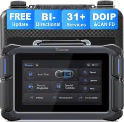
3. Overview of the Diagnostic Tool............................................................................ 4
3.1 Diagnostic Screen Layout & Icons......................................................................................... 4
3.2 Diagnostic Screen Layout.......................................................................................................... 4
3.3 Diagnostic Screen Icons............................................................................................................. 5
3.3.1 Auto Scan.............................................................................................................................. 5
3.3.2 Manual Diagnosis.............................................................................................................. 5
3.3.3 Special Function................................................................................................................. 5
3.3.4 Report..................................................................................................................................... 5
3.3.5 Updates................................................................................................................................. 5
3.3.6 More....................................................................................................................................... 5
3.3.7 Settings.................................................................................................................................. 5
3.3.8 Remote Control.................................................................................................................. 6
3.3.9 Service Center..................................................................................................................... 6
3.4 Hidden Toolbar, Home Screen Layout & Icons................................................................. 6
3.4.1 Hidden Toolbar................................................................................................................... 6
3.5 Home Screen Layout................................................................................................................... 7
3.6 Home Screen Icons...................................................................................................................... 7
3.6.1 Calender................................................................................................................................ 7
3.6.2 Camera................................................................................................................................... 8
3.6.3 Contacts................................................................................................................................. 8
3.6.4 Clock....................................................................................................................................... 9
3.6.5 Email....................................................................................................................................... 9
3.6.6 Music.................................................................................................................................... 10
3.6.7 Sound Recorder............................................................................................................... 10
3.6.8 Calculator........................................................................................................................... 11
3.6.9 ES File Explorer................................................................................................................. 11
3.6.10 Adobe Acrobat.............................................................................................................. 12
3.6.11 Quick Support................................................................................................................ 12
3.6.12 Endoscope....................................................................................................................... 13
3.6.13 Settings............................................................................................................................. 13
3.6.14 Gallery............................................................................................................................... 14
3.6.15 Video................................................................................................................................. 14
3.6.16 Explorer............................................................................................................................. 15
3.6.17 Chrome...................................................................................................................... 15
3.7 Data Transfer via USB Type-C ............................................................................................... 16

3.8 Red-Green Color Blindness Color Correction Mode.................................................... 17
3.9 FCA AutoAuth - SGW............................................................................................................... 17
4. Vehicle Diagnostics ............................................................................................... 18
4.1 My Vehicles .................................................................................................................................. 18
4.1.1 Compatibility Check ...................................................................................................... 18
4.2 Software Version ........................................................................................................................ 18
4.3 Demo Program ........................................................................................................................... 19
4.4 Trial Mode..................................................................................................................................... 19
4.5 Wi-Fi Connection....................................................................................................................... 19
4.6 Product Activation..................................................................................................................... 20
4.7 Connecting the Main Cable................................................................................................... 24
4.8 Vehicle Diagnostics ................................................................................................................... 25
4.8.1 Auto Scan .......................................................................................................................... 25
4.8.2 Manual Diagnosis........................................................................................................... 25
4.8.3 Automatic Detection ..................................................................................................... 25
4.8.4 Manual Selection ............................................................................................................ 25
4.9 Submit Feedback .......................................................................................................................26
4.10 CAN Fast Scan .......................................................................................................................... 26
4.11 System Selection ..................................................................................................................... 26
4.12 Diagnostics ................................................................................................................................26
4.12.1 Read Codes.....................................................................................................................26
4.12.2 Clear Codes ....................................................................................................................27
4.12.3 DTC Erased While Fault Remains............................................................................ 27
4.12.4 DTC Erased and Fault Fixed - History Code ....................................................... 27
4.12.5 DTC Erased and Fault Fixed - History Cleared................................................... 27
4.12.6 PID Data........................................................................................................................... 28
4.12.7 PID Data List...................................................................................................................28
4.12.8 Individual PID Data Graphing.................................................................................. 28
4.12.9 Set Maximum & Minimum Value Alarms ...........................................................29
4.12.10 Zoom in or Zoom out .............................................................................................. 30
4.12.11 Custom PID Data (Up to 8) ....................................................................................31
4.12.12 Individual Graphing for Up to 8 PIDs................................................................. 32
4.12.13 8-In-1 Graphing.......................................................................................................... 33
4.12.14 Fold/Unfold PID List ................................................................................................. 33
4.12.15 Data Recording........................................................................................................... 35
4.12.16 Export Data as CSV ................................................................................................... 35
4.12.17 CSV View....................................................................................................................... 36
4.12.18 Export CSV File to a PC............................................................................................ 38
4.12.19 Share CSV File via Bluetooth................................................................................. 38
4.12.20 Freeze Frame ............................................................................................................... 39
4.12.21 Active Tests (Bi-Directional Controls)................................................................. 40
4.12.22 Exiting Diagnostics.................................................................................................... 40
4.12.23 How to Exit...................................................................................................................41
4.13 Full System Diagnostic Report ...........................................................................................41
4.14 Fault Code Report ................................................................................................................... 42
4.15 Diagnostic Speed ....................................................................................................................44
4.16 Integrated Modules................................................................................................................ 44
5. OBDII/EOBD........................................................................................................... 44

5.1 OBDII Protocols..........................................................................................................................45
5.2 Basic Operations ........................................................................................................................45
5.3 Auto Scan & Protocol Selection .......................................................................................... 46
5.3.1 Auto Scan..................................................................................................................................46
5.3.2 Protocol Selection.................................................................................................................. 46
5.3.3 Help .............................................................................................................................................46
5.4 10 Modes of OBDII.................................................................................................................... 47
5.5 OBDII/EOBD Menu.................................................................................................................... 47
5.5.1 Read Trouble Code......................................................................................................... 47
5.5.1.1 Stored Codes ........................................................................................................... 48
5.5.1.2 Pending Codes ........................................................................................................ 48
5.5.1.3 Permanent Codes................................................................................................... 48
5.5.2 Generic & Manufacturer-Specific Codes...............................................................48
5.5.2.1 First DTC Character................................................................................................49
5.5.2.2 Second DTC Character ......................................................................................... 49
5.5.2.3 Third DTC Character..............................................................................................49
5.5.2.4 Fourth and fifth DTC Characters....................................................................... 50
5.5.3 Clear Trouble Code (Mode $04)................................................................................50
5.5.4 Live Data (Mode $01)....................................................................................................50
5.5.5 Read Freeze Frame (Mode $02) ................................................................................ 50
5.5.6 I/M Readiness (Smog Check) ..................................................................................... 50
5.5.6.1 Since DTCs Cleared................................................................................................ 51
5.5.6.2 This Driving Cycle...................................................................................................51
5.5.7 O2S Monitoring Test (Mode $05)............................................................................. 52
5.5.8 On-Board Monitor Test (Mode $06)........................................................................ 52
5.5.9 Component Test (Mode $08) ..................................................................................... 53
5.5.10 Read Vehicle Information (Mode $09)................................................................. 53
6. Special Functions & Maintenance Services........................................................ 53
6.1 Oil Reset ........................................................................................................................................ 53
6.2 EPB................................................................................................................................................... 56
6.3 SAS .................................................................................................................................................. 56
6.4 BMS Reset..................................................................................................................................... 59
6.5 Injector Coding........................................................................................................................... 61
6.6 TPMS Reset .................................................................................................................................. 64
6.7 ABS Bleeding ............................................................................................................................... 66
6.8 Power Balance.............................................................................................................................70
6.9 Seat Calibration..........................................................................................................................70
6.10 EEPROM ...................................................................................................................................... 70
6.11 Language Change................................................................................................................... 70
6.12 Transport Mode ....................................................................................................................... 70
6.13 Control Unit Reset................................................................................................................... 71
6.14 Throttle........................................................................................................................................71
6.15 A/F Reset ....................................................................................................................................71
6.16 HV Battery.................................................................................................................................. 71
6.17 Gearbox Match.........................................................................................................................71
6.18 Crank Sensor Relearn............................................................................................................. 71
6.19 Stop/Start Reset.......................................................................................................................71
6.20 EGR Relearn ............................................................................................................................... 71

6.21 A/C Relearn................................................................................................................................ 71
6.22 Headlight.................................................................................................................................... 71
6.23 SRS................................................................................................................................................72
6.24 Windows Initialization...........................................................................................................72
6.25 VGT Relearn ............................................................................................................................... 72
6.26 Coolant Bleeding..................................................................................................................... 72
6.27 Suspension................................................................................................................................. 72
6.28 Tire Size Reset........................................................................................................................... 72
6.29 Sunroof Initialization.............................................................................................................. 72
6.30 TCM Oil Reset ........................................................................................................................... 72
7. Settings .................................................................................................................. 72
7.1 Language ...................................................................................................................................... 72
7.2 Unit..................................................................................................................................................73
7.3 USB Setting ..................................................................................................................................74
7.4 Sound & Display ........................................................................................................................ 74
7.5 Storage Management ..............................................................................................................75
7.6 About.............................................................................................................................................. 75
8. Software Updates.................................................................................................. 76
9. More ....................................................................................................................... 77
9.1 Profile .............................................................................................................................................77
9.2 User Manual................................................................................................................................. 77
9.3 Vehicle Coverage ....................................................................................................................... 77
10. Other Settings ..................................................................................................... 77
10.1 Email Settings ........................................................................................................................... 77
10.2 Delete Email Account ............................................................................................................83
10.3 Printing Settings ...................................................................................................................... 85
10.3.1 Checklist for Installing Printing Service: .............................................................. 85
10.3.2 Install Mopria Print Service or Specialized Driver............................................ 85
10.4 For Printer with Wi-Fi Direct ............................................................................................... 90
11. Service Center ..................................................................................................... 90
11.1 Remote Control........................................................................................................................ 91
11.2 Schedule a Remote Control ................................................................................................ 92
11.3 Data Logging ............................................................................................................................93
12. Compliance Information .................................................................................... 93
12.1 Regulatory Compliance Statements................................................................................. 93
12.2 RF Exposure & SAR (FCC & ISED) .....................................................................................94
12.3 Additional Compliance (RoHS, CE & UKCA) ................................................................. 94
13. Warranty.............................................................................................................. 94
14. Contact Us............................................................................................................ 95
15. Appendix ............................................................................................................. 96
15.1 Navigation Path Quick Reference.....................................................................................96
15.2 Terms & Terminology Quick Reference .......................................................................... 96
15.3 FAQs .............................................................................................................................................96
1
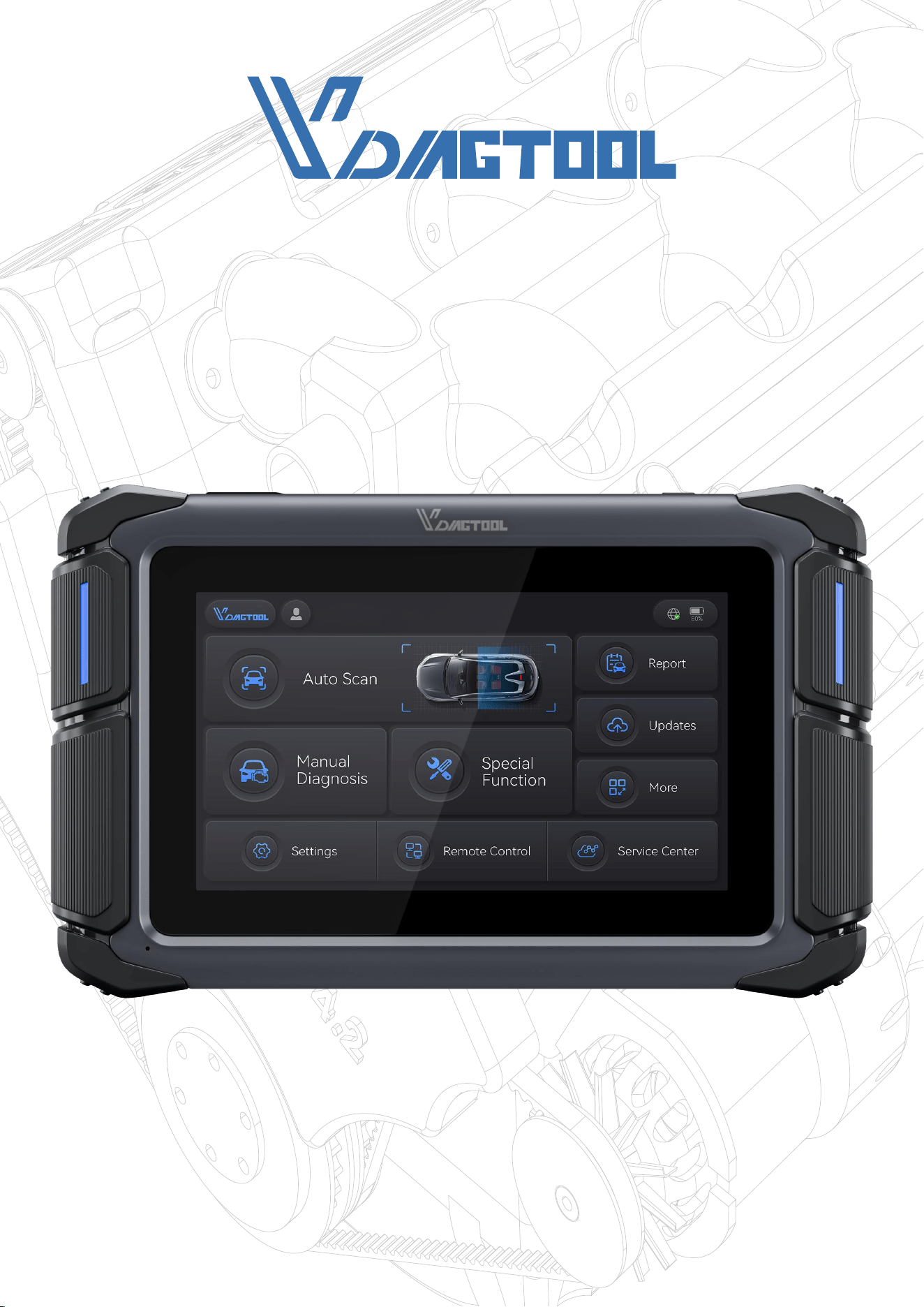
VD70 Lite Diagnostic Tool
1. Introduction
The VDIAGTOOL VD70 Lite diagnostic tool is designed to interface with a vehicle’s Electron-
ic Control Unit (ECU), enabling users to retrieve diagnostic trouble codes (DTCs), access
real-time data streams, and perform active tests (bi-directional controls). It supports com-
prehensive diagnostics across multiple vehicle systems—including engine, transmission,
anti-lock braking system (ABS), SRS (airbag), chassis, body, and more.
The tool allows simultaneous graphing of up to eight live data parameters on a single
screen for efficient analysis and also provides detailed ECU information.
This chapter offers an overview of the diagnostic tool’s core features, covering control but-
tons, data ports, battery pack, and power options. Technical specifications are provided at
the end of the chapter.
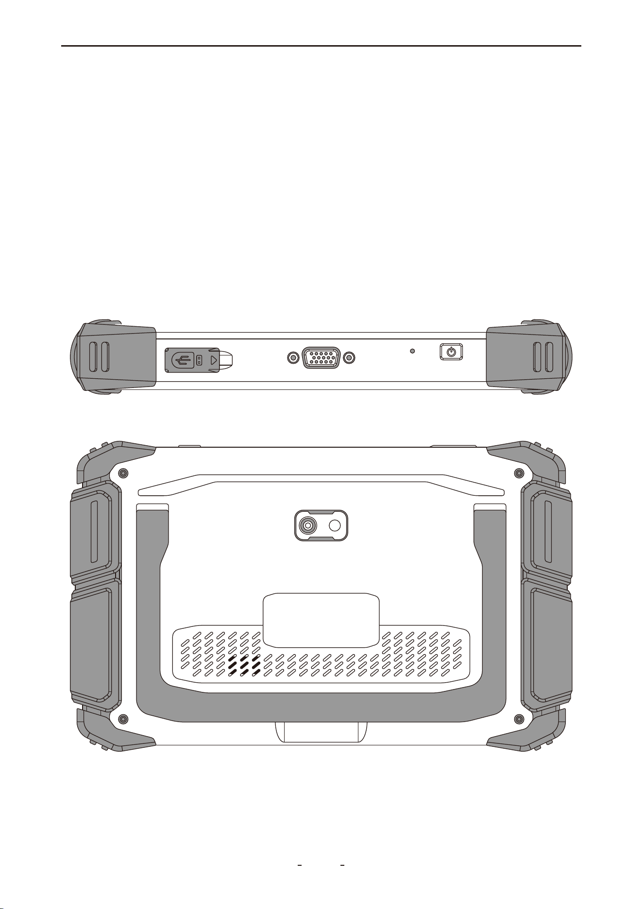
1.1 Data and Power Connections
1.2 Battery Pack and Stand

2
VD70 Lite Diagnostic Tool
Item Description / Specification
7-inch touch screen, 1024 × 600 resolution
Android 10.0
Quad-core, 1.5 GHz
2GB RAM + 64GB ROM
Bluetooth 4.1, Wi-Fi (2.4GHz & 5GHz), Type-C
Gravity accelerometer, Ambient light sensor
Built-in microphone
Built-in speaker
8-megapixel
3.5 hours (continuous operation)
9V – 36V
18.25Wh
(DC 7.3V, Rechargeable Li-ion, 2500mAh)
Input: 100–240V AC
Output: 5.0V⎓3.0A
Display
Operating System
Processor
Memory
Connectivity
Sensor
Audio
Speaker
Camera
Tested Battery Life
Operating Voltage
Battery Capacity
Power Adapter
240 × 150 × 36.4 mm (9.45 × 5.91 × 1.43 in)
Dimensions
0.91 kg (2.0 lbs)
Net Weight
2.2 kg (4.85 lbs)
Gross Weight
0°C to 40°C (32°F to 104°F)
Operating Temperature
1.3 Power Sources
The VDIAGTOOL VD70 Lite diagnostic tool can be powered by either of the following sourc-
es:
● Internal Battery Pack
● AC Power Supply
1.4 Internal Battery Pack
The tool is equipped with an internal rechargeable battery that supports approximately 3.5
hours of continuous operation on a full charge.
The battery charges automatically when the device is connected to the AC power supply
and a functioning AC power outlet.
1.5 AC Power Supply
The diagnostic tool can also be operated via a standard AC outlet using the provided AC
power adapter. Connect the output cable of the adapter to the DC input jack located on the
top of the device.
To ensure safety and compatibility, use only the original AC power supply included with the
tool.
1.6 Technical Specifications

Item
Description / Specification
-10°C to 50°C (14°F to 122°F)
Storage Temperature
<90% RH (non-condensing)
Operating Humidity
2. Getting Started
Ensure the diagnostic tool is adequately charged or connected to an external power source
(refer toPower Sourceson page 2 for details).
Note:
The images and illustrations shown in this manual are for reference only and may differ
slightly from the physical product.
Powering On, Off, and Force Restart
This section explains how to turn the VDIAGTOOL VD70 Lite diagnostic tool on and off, as
well as how to perform an emergency shutdown when necessary.
2.1 Powering On
To turn on the device, press and hold the power button (located on the top-right side) for
3 seconds. The tool will power on if the battery is sufficiently charged or if it is connected to
the AC power adapter.
If the battery is completely drained, allow the device to charge for a few minutes before
attempting to turn it on.
2.2 Powering Off
To turn off the device, press and hold the power button for more than 3 seconds. The diag-
nostic tool will shut down automatically.
1.7 What’s In The Box
VD70 Lite Diagnostic Tool
Type-C to Type-C Charger Cable
Power Adapter (US Standard)
Power Adapter (EU Standard)
Type-C to Type-A Adapter (for PC Connection)
1
Item
Quantity
1
1
1
1
Power Adapter (UK Standard)
Color Retail Box
Quick Start Guide
Packing List
DB15 Main Cable
1
1
1
1
Protective Hard Case
1
1
3
VD70 Lite Diagnostic Tool

Important:
Always terminate all vehicle communication before powering off the diagnostic tool. A
warning message will appear if you attempt to turn off the device while it is actively com-
municating with the vehicle.
Forcing a shutdown during communication may cause errors in the vehicle's ECM on certain
models.
Never disconnect the DB15 main cable while the tool is communicating with the vehicle
ECU.
2.3 Emergency Shutdown
Under normal circumstances, always power off the device using the standard procedure
described in section 2.2. The emergency shutdown procedure should only be used if the
diagnostic tool becomes unresponsive to button input or exhibits abnormal behavior.
To perform an emergency shutdown, press and hold the power button for 5 seconds until
the device powers off.
Important:
Using emergency shutdown during active communication with a vehicle ECU may cause
ECU malfunctions on certain models.
3. Overview of the Diagnostic Tool
This chapter introduces the main diagnostic screen layout, key interface icons, and the
Android system home screen along with its primary icons.
3.1 Diagnostic Screen Layout & Icons
Upon powering on, the diagnostic tool automatically launches the diagnostic application.
The main diagnostic screen will appear once the program is loaded.
A hidden toolbar is located at the bottom of the screen. Swipe upward from the bottom
edge to temporarily display the toolbar, which remains visible for 3 seconds.
This section illustrates the layout of the diagnostic screen and the icons available in the
toolbar.
3.2 Diagnostic Screen Layout
4
VD70 Lite Diagnostic Tool
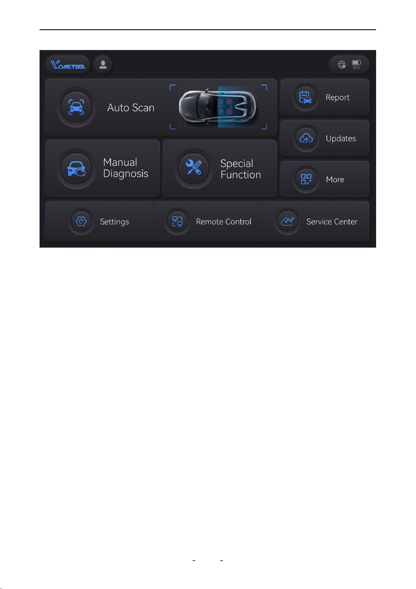
3.3 Diagnostic Screen Icons
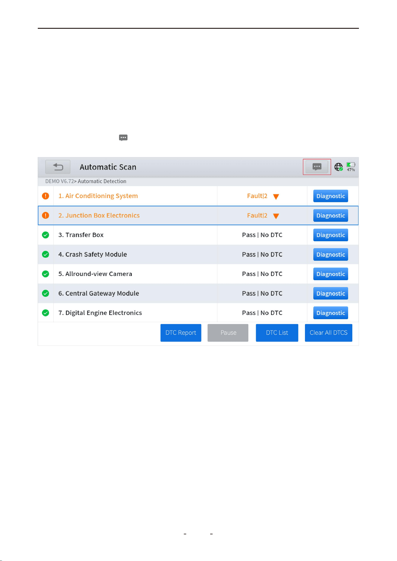
3.3.1 Auto Scan
Automatically identifies and decodes the vehicle's VIN, then performs a comprehensive
diagnostic scan of all accessible electronic control modules.
3.3.2 Manual Diagnosis
Select this icon to access the diagnostic menu. From here, you can choose to identify the
vehicle automatically by VIN, or manually specify the make, model, year, and other configu-
rations. This section also provides access to the DEMO program and standard OBDII tests.
3.3.3 Special Function
This section provides access to commonly used vehicle maintenance and service functions,
offering practical support for both DIY enthusiasts and professional technicians.
3.3.4 Report
This section provides access to diagnostic reports, data playback, and data review functions.
3.3.5 Updates
This section enables you to download diagnostic software updates individually or in batch.
3.3.6 More
This section allows you to manage user accounts and workshop profiles (where applicable),
check subscription status, view firmware information, access the endoscope tool, and open
the user manual in PDF format.
3.3.7 Settings
This section enables configuration of the diagnostic software language, measurement units,
and USB mode. It also provides access to OS settings, including volume and display bright-
5
VD70 Lite Diagnostic Tool

Screenshot icon: Takes a screenshot on what’s on the screen.
Volume Down icon: Decreases the speaker volume.
Volume Up icon: Press to increase the speaker volume.
Diagnostic icon: Press to quickly launch the diagnostic application.
Screen Recorder icon: Press to start recording the screen and audio. Press again to stop
recording.
Home icon: Returns to the Android home screen.
Task List icon: Displays all ongoing tasks. Swipe up the respective task screen to kill the
task.
Back icon: Returns to the previous menu or screen.
ness adjustment. Additionally, you can view application version, OS version, diagnostic tool
serial number, and VCI number here.
3.3.8 Remote Control
Select this icon to launch TeamViewer for remote assistance. Ensure TeamViewer is in "ready
to connect" mode before your scheduled remote session. The TeamViewer ID is displayed
on the right, and the connection status is shown at the bottom left of the screen.
3.3.9 Service Center
This section provides contact information and official social media accounts for customer
support and other inquiries.
3.4 Hidden Toolbar, Home Screen Layout & Icons
Swipe up from the bottom of the touchscreen to reveal the toolbar, which remains visible
for 3 seconds. Tap the Home button on this toolbar to access the Android home screen of
the diagnostic tablet.
The following sections describe the layout of the home screen and the functions of its
primary icons.
3.4.1 Hidden Toolbar
6
VD70 Lite Diagnostic Tool
3.5 Home Screen Layout
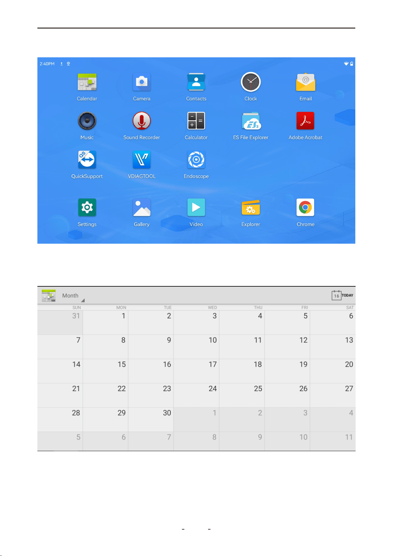
3.6 Home Screen Icons
3.6.1 Calender
Displays the calendar in day, week, or month view.
7
VD70 Lite Diagnostic Tool
3.6.2 Camera
Activates the rear camera to capture images of vehicle components or issues.
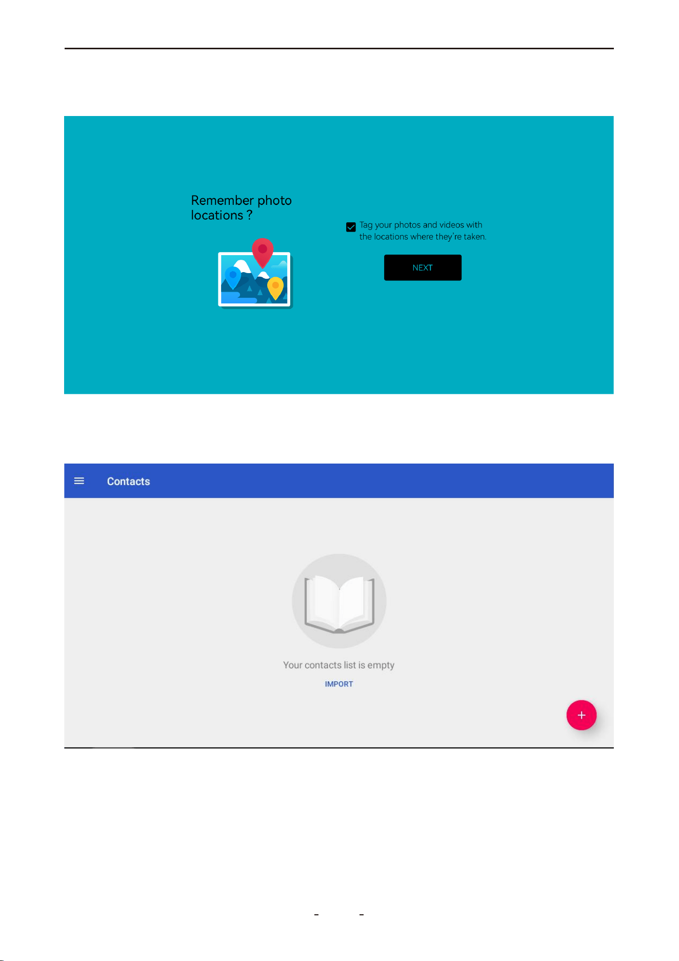
3.6.3 Contacts
Manage your contact list, add new contacts using the "+" icon, or import multiple contacts
from a vcf file.
8
VD70 Lite Diagnostic Tool
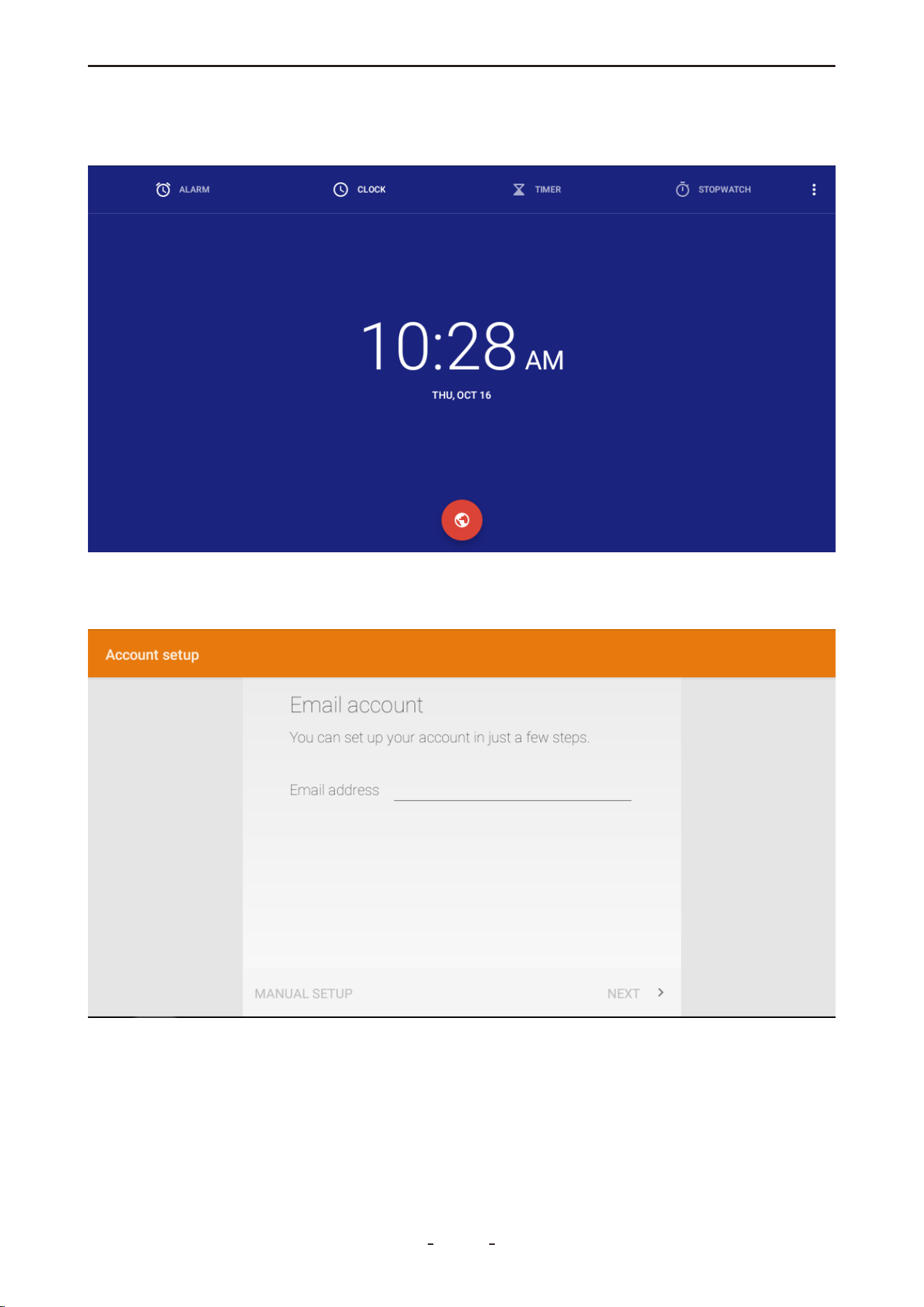
3.6.4 Clock
Set alarms, timers, use the stopwatch, or view the current time.
3.6.5 Email
Set up email accounts to send messages or share diagnostic reports.
9
VD70 Lite Diagnostic Tool
3.6.6 Music
Play songs, create playlists, and manage music by albums or artists.
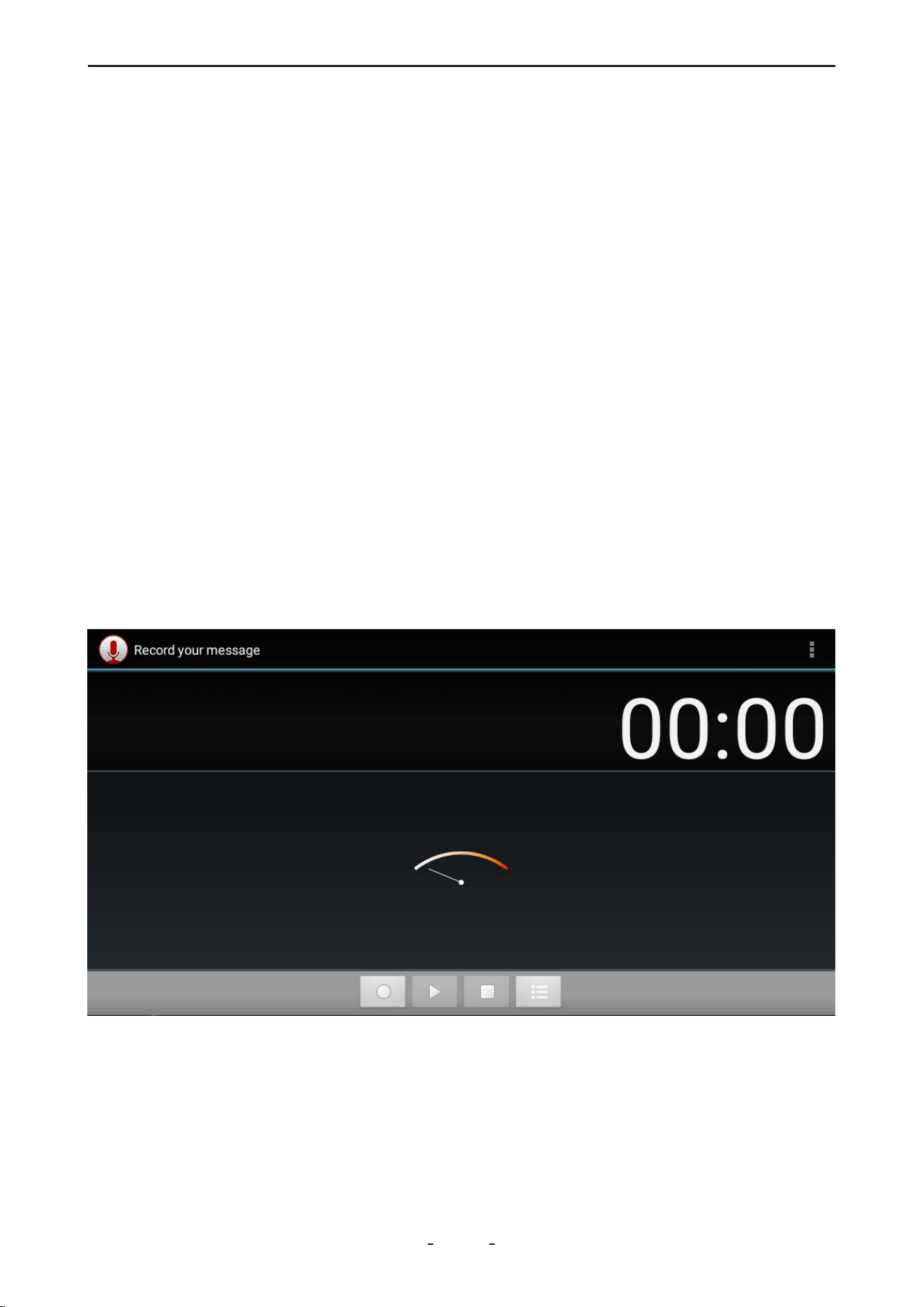
3.6.7 Sound Recorder
Record and play back audio messages.
10
VD70 Lite Diagnostic Tool
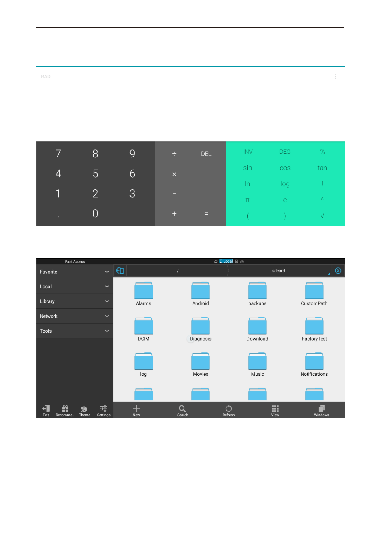
3.6.8 Calculator
Perform basic mathematical calculations.
3.6.9 ES File Explorer
Manage documents, reports, and other files stored in the device memory.
11
VD70 Lite Diagnostic Tool
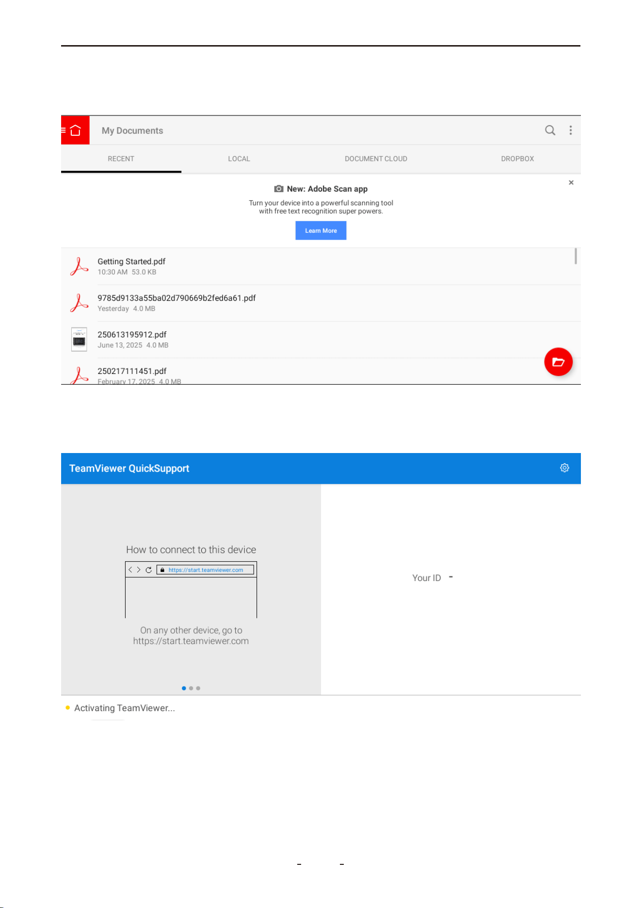
3.6.10 Adobe Acrobat
View and manage PDF files. Connect to Dropbox with your accounts.
3.6.11 Quick Support
Allows our technical team to remotely control the tool to diagnose issues or provide guid-
ance.
12
VD70 Lite Diagnostic Tool
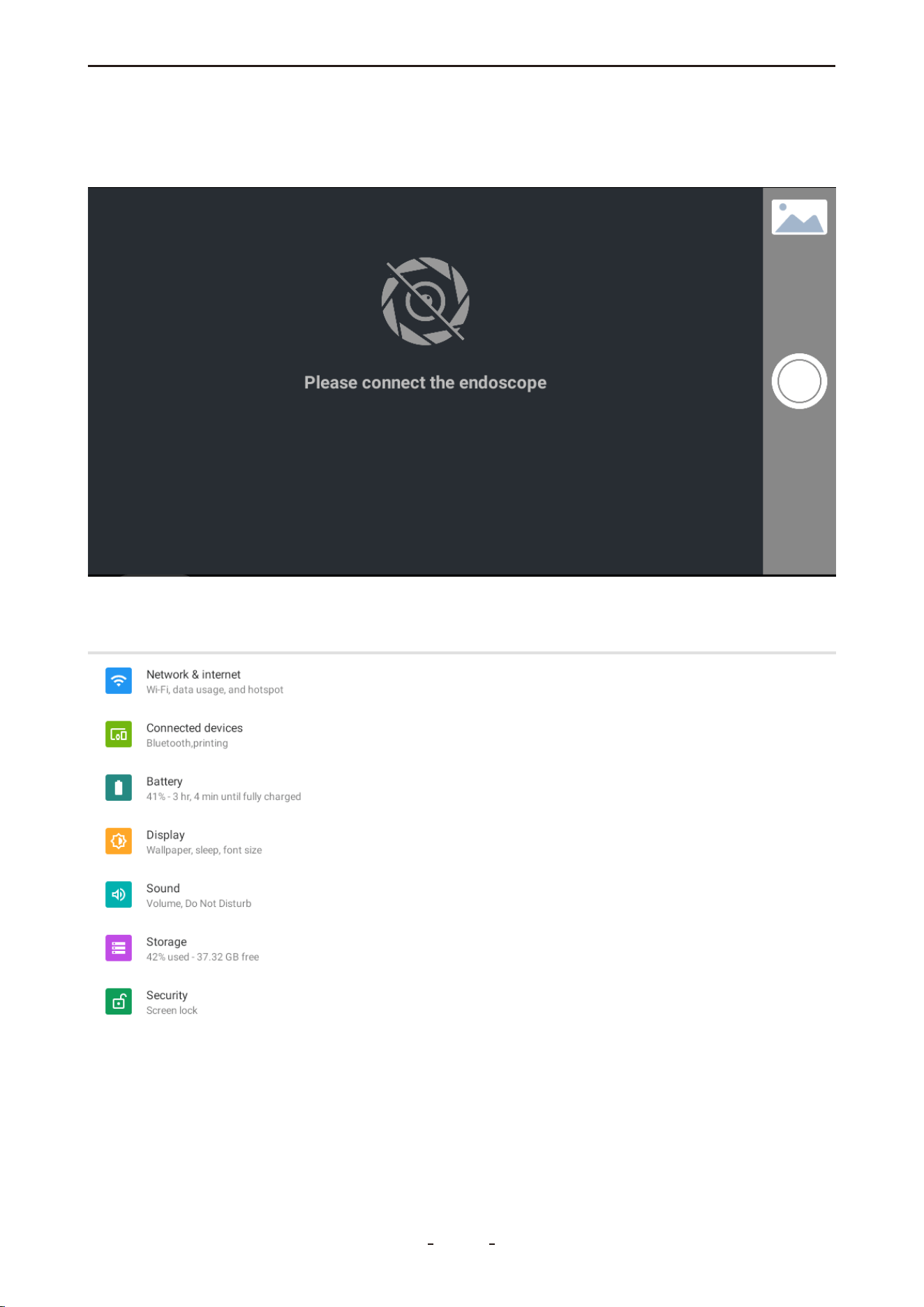
3.6.12 Endoscope
Use a connected endoscope for visual inspection. If no endoscope is connected, the built-in
camera will activate automatically.
3.6.13 Settings
Configure system settings including Wi-Fi, battery, display, sound, and storage...
13
VD70 Lite Diagnostic Tool
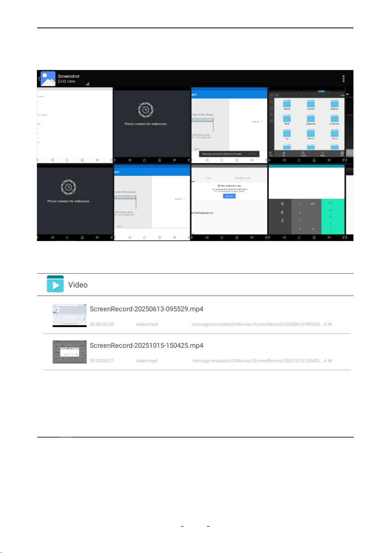
3.6.14 Gallery
View screenshots, camera photos, and screen recordings.
3.6.15 Video
Play recorded videos and screen recordings.
14
VD70 Lite Diagnostic Tool
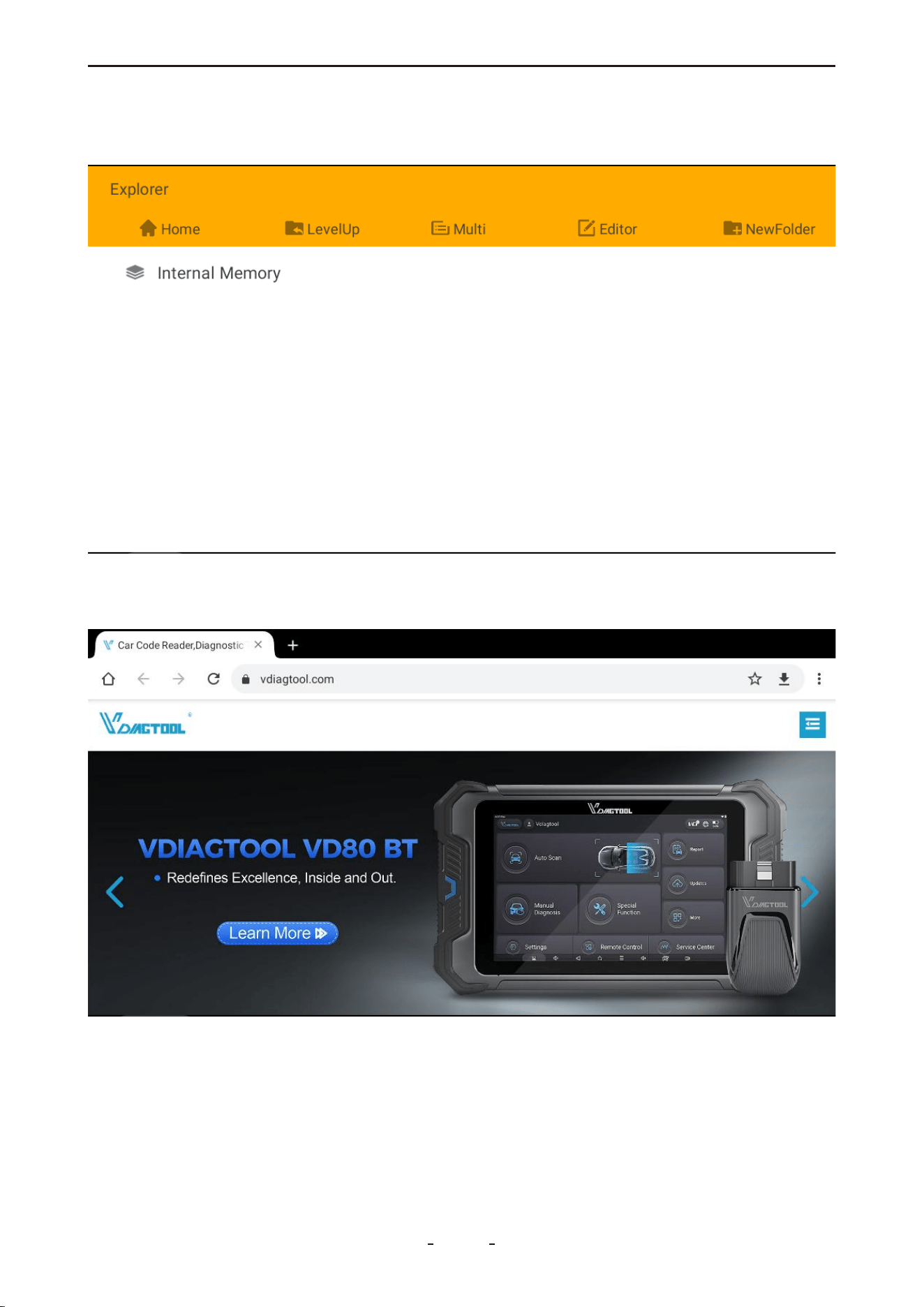
3.6.16 Explorer
Browse and manage files in internal memory.
3.6.17 Chrome
Browse the web to search for fault codes and other information.
15
VD70 Lite Diagnostic Tool
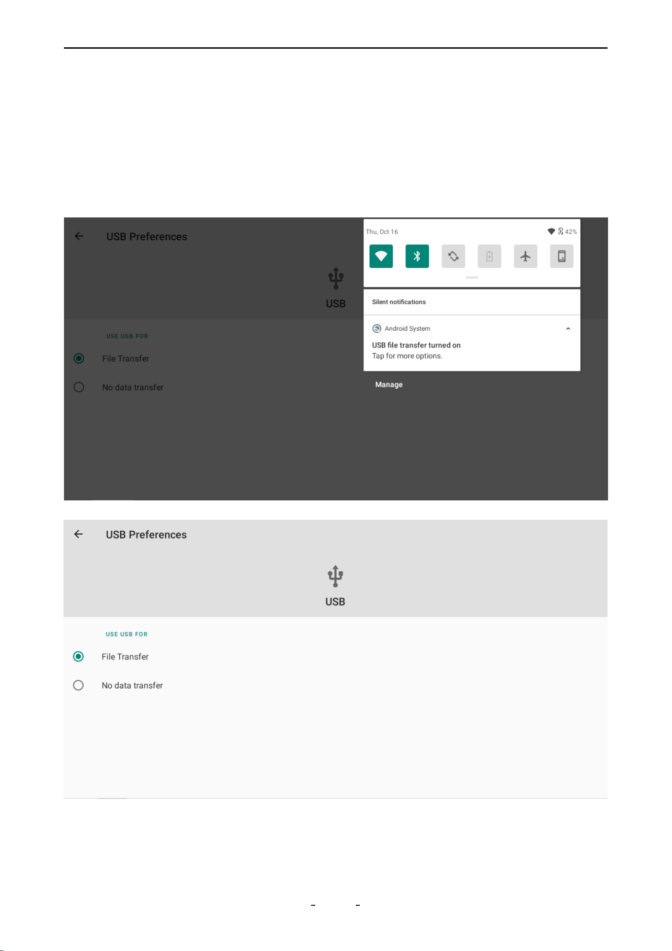
3.7 Data Transfer via USB Type-C
To transfer data between the diagnostic tool and a PC:
1. Connect the tool to a PC using the Type-C cable (to the device's Type-C port and the PC's
USB port).
2. Swipe down from the top of the screen to open the notification panel and tap Android
System → Charging this device via USB.
3. Select File Transfer.
4. On the PC, open VD70 Lite to access files.
16
VD70 Lite Diagnostic Tool
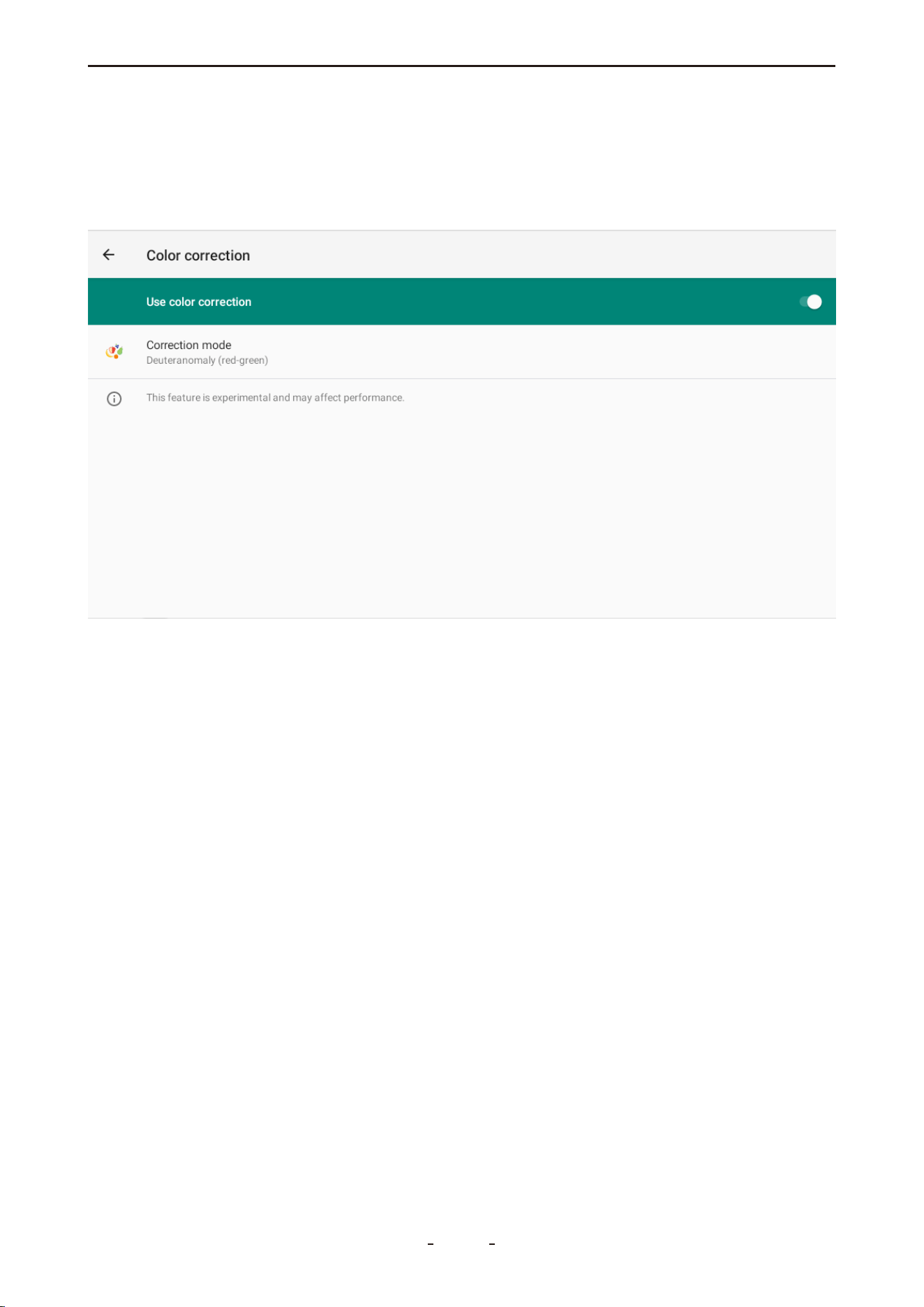
3.8 Red-Green Color Blindness Color Correction Mode
To enable color correction mode:
1. Swipe up from the bottom to show the toolbar.
2. Tap the Home button to go to the Android home screen.
3. Go to Settings → Accessibility → Color correction and turn on Use color correction.
3.9 FCA AutoAuth - SGW
Security Gateway Module(SGW) - In 2018, the SGW was implemented by FCA USA to pre-
vent unauthorized access. FCA said that SGW was developed to limit "the ability of non-reg-
istered and non-authenticated users to perform intrusive diagnostics such as “bi-directional
controls", so users cannot directly clear the DTC, as well as any bi-directional control test(in-
cluding actuation, relearn and calibration) on vehicles equipped with SGW.
VDIAGTOOL receives Certification by FCA to access SGW Module, and perform previously
restricted actions, by registering with AutoAuth, an authentication service. VDIAGTOOL
tablet scanner users can register through AutoAuth's Internet-based registration portal for
$50 a year. (Note: This fee is NOT charged by VDlAGTOOL company.)
You can now access the SGW module and perform operations that were previously restrict-
ed by registering with the AutoAuth authentication service. This process eliminates the
need for additional accessories. Users begin by registering through AutoAuth's web-based
portal, selecting their desired package, and adding their VDlAGTOOL diagnostic tool.
The information above indicates that if you cannot find "Transmission" or a similar name in
the diagnostic menu, you should locate "Transmission Oil Temperature" under the PlD
data(live data) menu of the Powertrain Control Module(or PCM). Similarly, if you are looking
for the ABS Bleeding feature, you should go to the Special Function under the Brake Control
Module (BCM). This approach helps navigate and locate specific diagnostic features within
the diagnostic tool's interface
17
VD70 Lite Diagnostic Tool

4. Vehicle Diagnostics
This chapter outlines the basic operation of the diagnostic function.
The Diagnosis icon is located on the home screen. This function enables communication
with the vehicle's electronic control systems, allowing you to:
● Retrieve diagnostic trouble codes (DTCs)
● View live PID data
● Perform active tests
● Access additional diagnostic functions
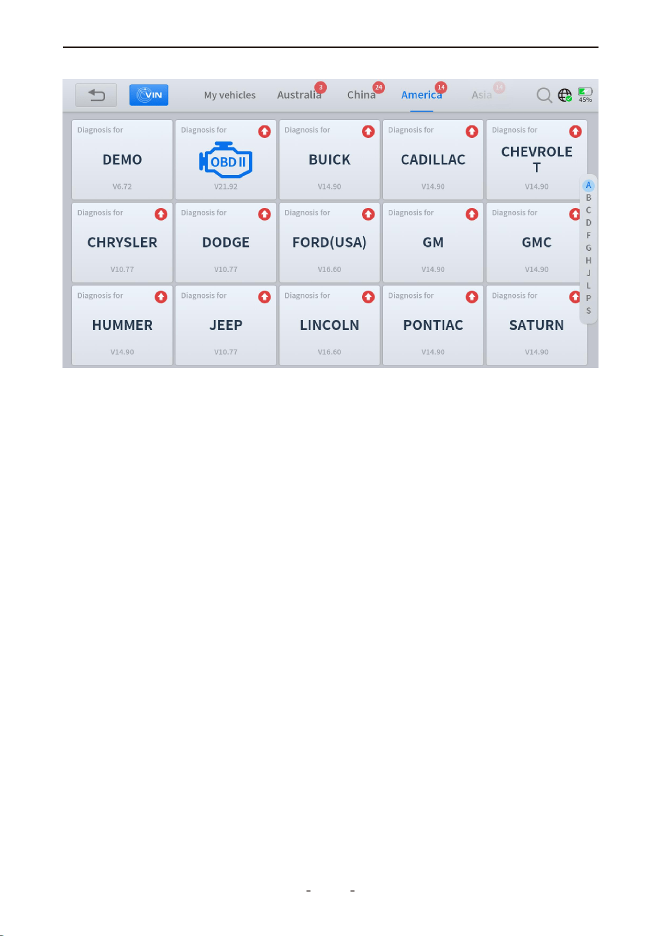
4.1 My Vehicles
The "My Vehicles" function allows you to save frequently used diagnostic programs for
quick access.
To locate this feature, tap the Manual Diagnosis icon on the diagnostic screen. "My Vehi-
cles" will be displayed in the top taskbar.
Adding Programs: Tap the "+" (add) icon, select the region of the vehicle brand, choose
the desired brand(s), and tap "Complete" to confirm.
Removing Programs: Tap the pen (edit) icon, select the program(s) to remove, and tap
"Remove" to confirm.
4.1.1 Compatibility Check
This diagnostic tool supports all OBDII/EOBD compliant vehicles for generic code reading
and basic functions. It also covers a wide range of specifi c makes and models across the
United States, Europe, Asia, Australia, and other regions for full-system diagnostics. Note
that available functions may vary significantly, even between vehicles of the same make,
model, and year.
Important:
Special Functions on the main diagnostic screen are not universally available for all vehicles.
Feature availability is strictly determined by vehicle compatibility based on the VIN, make,
model, and year.
To verify compatibility, contact support at [email protected] or view the online refer-
ence list at: https://www.vdiagtool.com/support/vehicle-coverage
(Note: The online list is for reference only and must be confirmed with technical support.)
4.2 Software Version
The current software version for each vehicle manufacturer is displayed at the bottom of its
selection tile. For example, the installed HONDA software version is shown as V12.40 in the
illustration below.
18
VD70 Lite Diagnostic Tool
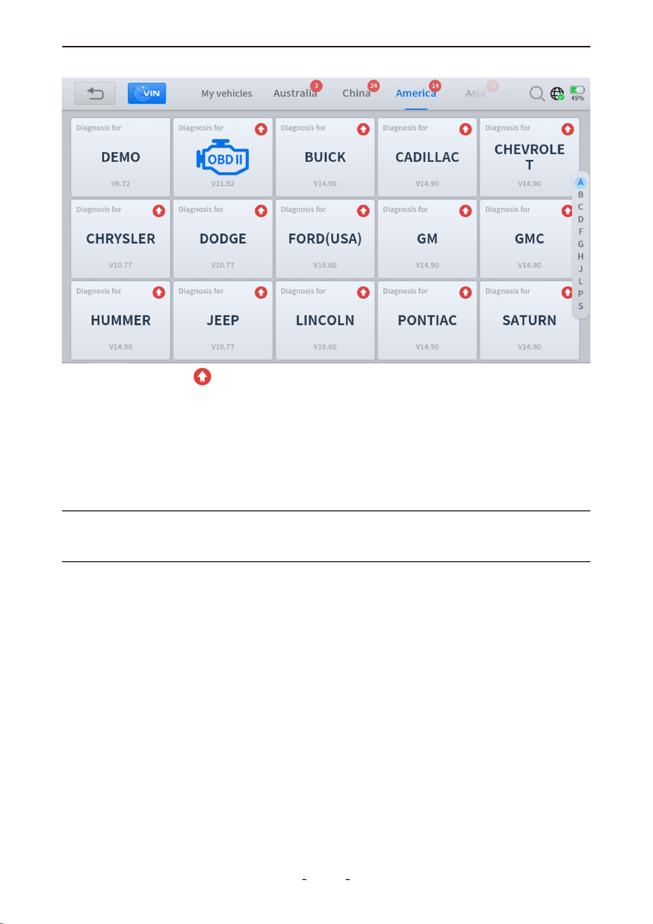
The red upward arrow indicates that a newer software version is available for download.
After you click the arrow to update and install the software, the diagnostic tool will display
the newly installed version.
4.3 Demo Program
The DEMO program simulates the vehicle navigation process, available functions, and
menu interfaces. You can use it to practice operating the diagnostic tool before performing
actual vehicle diagnostics.
Important:
The DEMO program may not reflect the latest diagnostic procedures or actual vehicle
screens. It is not intended for verifying vehicle coverage or compatibility.
4.4 Trial Mode
The diagnostic tool includes a limited number of trial uses. These allow you to evaluate its
functions and check vehicle compatibility before activating a full subscription. The number
of available trials may vary based on factory inspection procedures (including routine and
random sampling).
4.5 Wi-Fi Connection
The diagnostic tool supports connections to both 2.4 GHz and 5.0 GHz Wi-Fi networks.
To connect to Wi-Fi:
1. Swipe up to show the toolbar and tap Home.
2. Go to Network & internet and turn on Wi-Fi.
3. Tap the Wi-Fi icon, select a network, and enter the password.
To use a mobile hotspot:
19
VD70 Lite Diagnostic Tool

If Wi-Fi is unavailable, you can use your phone's hotspot.
● iOS: Enable Allow Others to Join and Maximize Compatibility in Settings > Personal
Hotspot.
● Android: Enable the portable hotspot in Settings > Wireless & networks > Tethering
& portable hotspot. Set encryption to WPA2 PSK and ensure a connection slot is avail-
able.
Note:
Wi-Fi is not required for diagnosing most vehicles. It is only necessary for certain brands
(e.g., Peugeot) that require online server access during diagnostics.
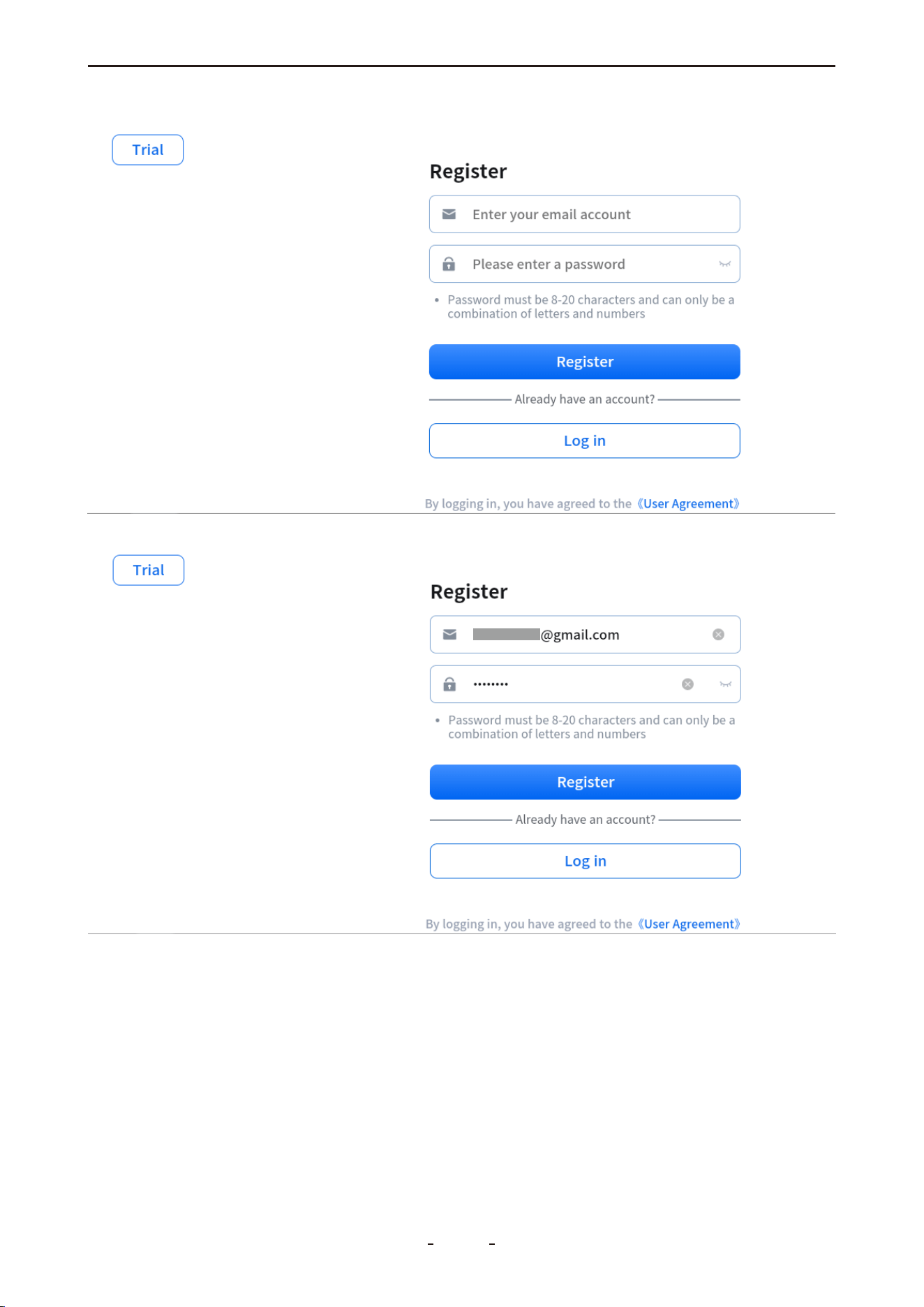
4.6 Product Activation
When the trial period ends, you must register and activate the diagnostic tool to continue
using all diagnostic functions.
To activate the product:
1. Tap Register.
2. Enter your email address.
3. Set and confirm your password.
4. Agree to the User Terms and submit.
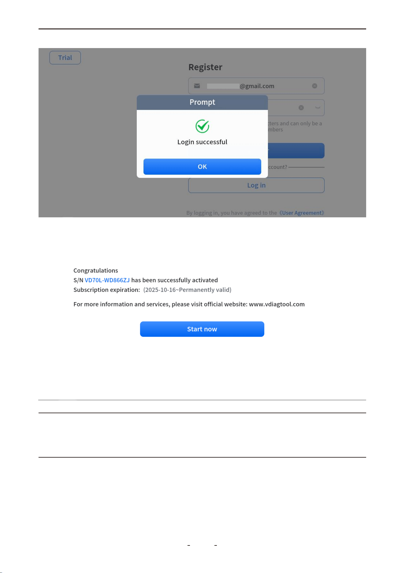
Once the registration complete message appears, the tool is activated. Your login creden-
tials will be saved, and no repeated logins are required for future use.
20
VD70 Lite Diagnostic Tool
21
VD70 Lite Diagnostic Tool
Note:
If you are unable to register or do not see the activation screen, please contact our support
team at [email protected] or complete the technical support form on our website
www.vdiagtool.com for immediate assistance.
22
VD70 Lite Diagnostic Tool
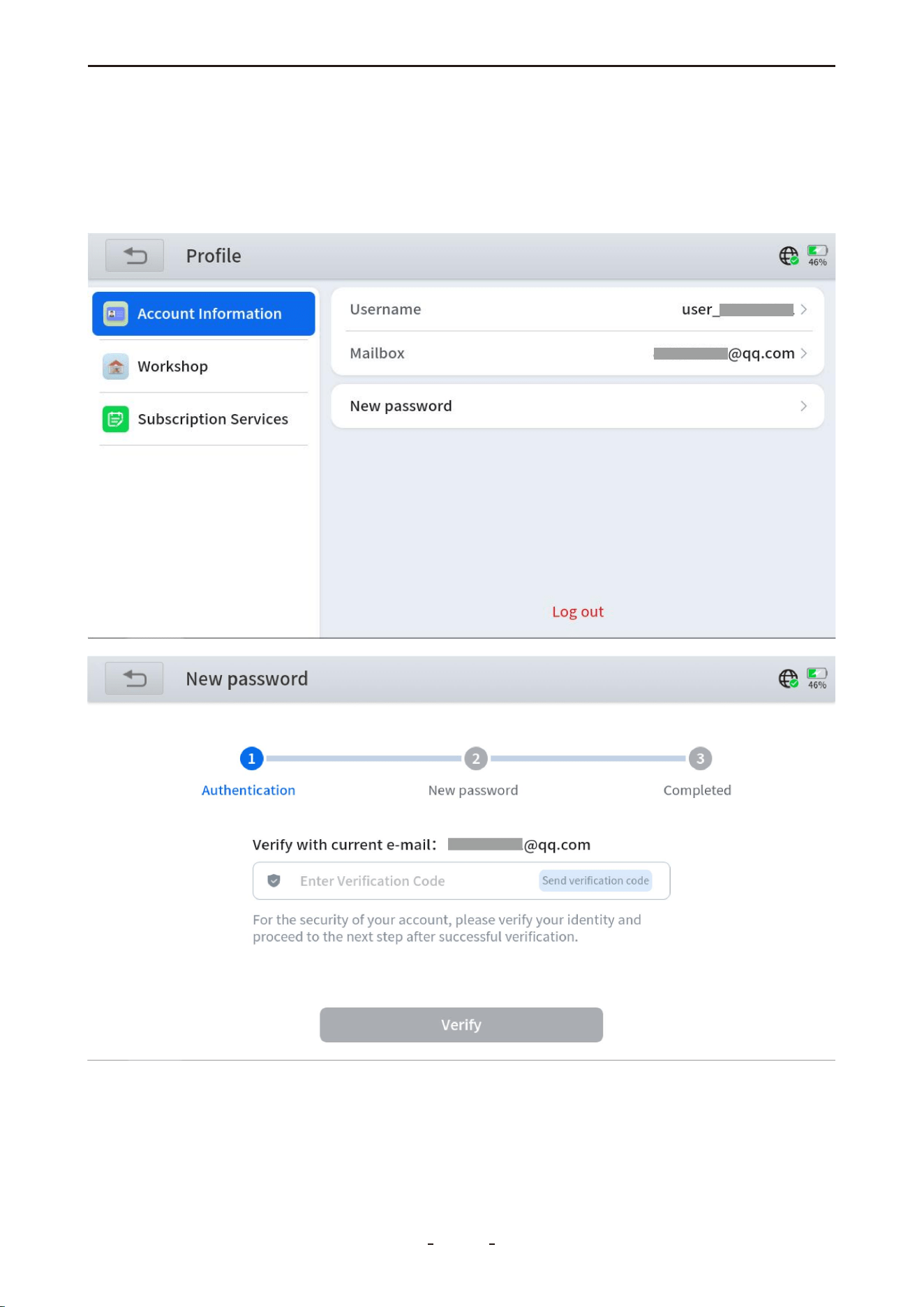
Password Reset:
If you forget your password, tap“New password”, enter your email address, and select
“Get verification code”. You will receive a verification code fromnoreply@service-vdiag-
tool.com. Enter the code to reset your password. If the code is not in your inbox, please
check your spam folder.
If you have forgotten the email address used for activation, please email the diagnostic
tool's S/N (Serial Number) to [email protected] to retrieve your registration details.
23
VD70 Lite Diagnostic Tool
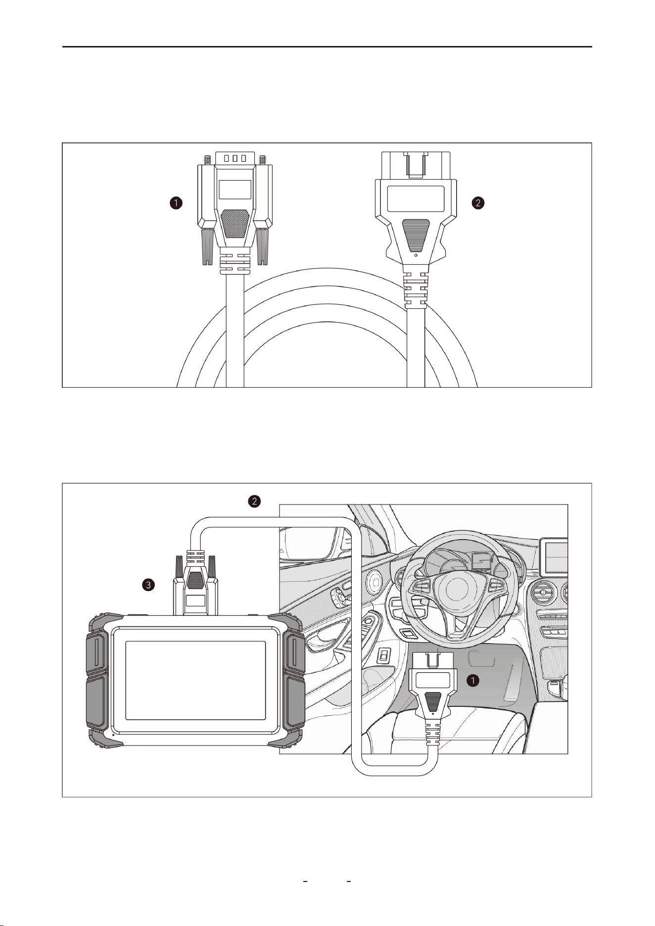
4.7 Connecting the Main Cable
The diagnostic tool uses a main cable with a DB15 male connector on one end (for the tool)
and an OBDII-16 male connector on the other end (for the vehicle) to establish communica-
tion.
➊DB15 Male Connector- Connects to the DB15 port on the diagnostic tool
➋OBDII-16 PIN Male Connector- Connects to the vehicle's OBDII port
To establish communication between the diagnostic tool and the vehicle, please follow the
steps below:
➊Vehicle ➋DB15 to OBDII-16 Main Cable ➌Diagnostic Tool
24
VD70 Lite Diagnostic Tool

1. Power on the diagnostic tool.
2. Connect the DB15 male connector to the tool's DB15 female port and secure the screws.
3. Plug the OBDII-16 male connector firmly into the vehicle's OBDII port.
4. Turn the ignition to the "ON" position and launch the diagnostic program.
4.8 Vehicle Diagnostics
Accurate vehicle identification is required for the diagnostic tool to establish communica-
tion and perform diagnostics. The identification process is menu-guided—follow the
on-screen prompts to enter the necessary information. Specific steps may vary depending
on the vehicle's make, model, and year.
You can identify a vehicle using one of the following four methods:
4.8.1 Auto Scan
Tap the Auto Scan icon on the diagnostic screen. The tool will automatically scan and
decode the vehicle's VIN to identify it.
Important:
A common misconception is that the tool cannot diagnose a vehicle if it fails to read or
decode the VIN. If Auto Scan fails, try alternative identification methods. Manual Selection
remains the most reliable fallback option.
Note:
Auto Scan is not supported on all vehicles. If unsuccessful, please use another identification
method.
4.8.2 Manual Diagnosis
Tap the Manual Diagnosis icon on the diagnostic screen to open the vehicle selection
menu. Then, tap the icon in the top left corner to access the Auto Scan and Manual
Input options. Select Manual Input to enter the 17-digit VIN manually. The tool will
decode the VIN and identify the vehicle.
Note:
Some VINs cannot be decoded. If both Auto Scan and Manual Input fail, try Automatic
Detection or Manual Selection instead.
4.8.3 Automatic Detection
Tap Manual Diagnosis, select the region of the vehicle brand (e.g., Americas), choose the
brand (e.g., CADILLAC), and then select Automatic Detection to allow the tool to automati-
cally identify the connected vehicle.
Note:
Automatic Detection is not supported on all vehicle models. If this method fails, please use
Manual Selection.
4.8.4 Manual Selection
If Auto Scan, Manual Input, and Automatic Detection fail to identify the vehicle, use
Manual Selection—the most reliable method—to proceed with diagnostics.
25
VD70 Lite Diagnostic Tool
To identify a vehicle manually:
1. Tap Manual Diagnosis.
2. Select the vehicle brand's region (e.g., Americas).
3. Choose the brand (e.g., CADILLAC).
4. Select Manual Selection.
5. Specify the model year, model name, and any subsequent options until Automatic Scan
and System Selection appear.
4.9 Submit Feedback
Tap the message icon in the top right corner to submit feedback to our support team
regarding any issues with the app or software.
4.10 CAN Fast Scan
Rapidly scans all accessible vehicle systems for post-2005 vehicles using CAN protocol
communication.
4.11 System Selection
Select a specific vehicle control module for diagnostics when you already have an idea
which system may be causing issues.
4.12 Diagnostics
After successful vehicle identification, the diagnostic tool can scan and access the vehicle's
electronic control systems to retrieve diagnostic trouble codes (DTCs), read PID data
(Parameter IDs), view freeze frame information, access ECU details, and perform tests such
as active tests (bi-directional controls), and more.
4.12.1 Read Codes
Displays diagnostic trouble code (DTC) records stored in the vehicle's electronic control
26
VD70 Lite Diagnostic Tool
modules. Selecting this option may open a submenu with additional viewing choices.
If the tool displays “System is OK” or “No Trouble Code”, this may indicate:
● No relevant fault codes are stored in the ECU;
● The fault is not within that specific ECU's domain (e.g., mechanical or circuit issues);
● A sensor signal is abnormal but still within its operational range — such cases can be
further analyzed using Live Data (PID).
4.12.2 Clear Codes
Erases both current and historical DTC records, along with related data, from the vehicle's
electronic control modules.
After initiating the erase command, the ECU will verify whether the issue has been resolved
over several drive cycles. Note that:
● Some faults can be detected immediately with the ignition on, even if the engine is off.
● Other faults require specific conditions to be met (e.g., engine coolant temperature, vehi-
cle speed, or throttle position within certain ranges for a defined duration) before they can
be detected again.
4.12.3 DTC Erased While Fault Remains
If DTCs are cleared while the underlying fault persists, the codes will reappear after one or
more drive cycles.
4.12.4 DTC Erased and Fault Fixed - History Code
If a fault has been repaired but a code remains stored, the ECU may either automatically
clear it or reclassify it as a history code.
4.12.5 DTC Erased and Fault Fixed - History Cleared
Clearing codes after a repair removes the fault history. Note that clearing codes is generally
not recommended before another technician reviews the vehicle, as valuable diagnostic
27
VD70 Lite Diagnostic Tool
31%
information may be lost.
Note:
Clearing codes will also erase freeze frame data.
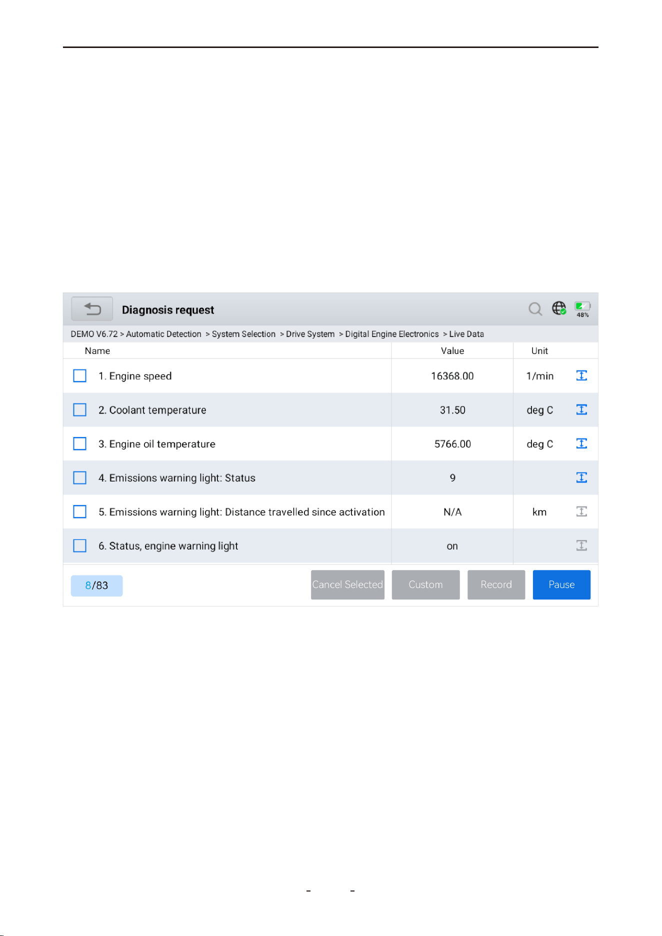
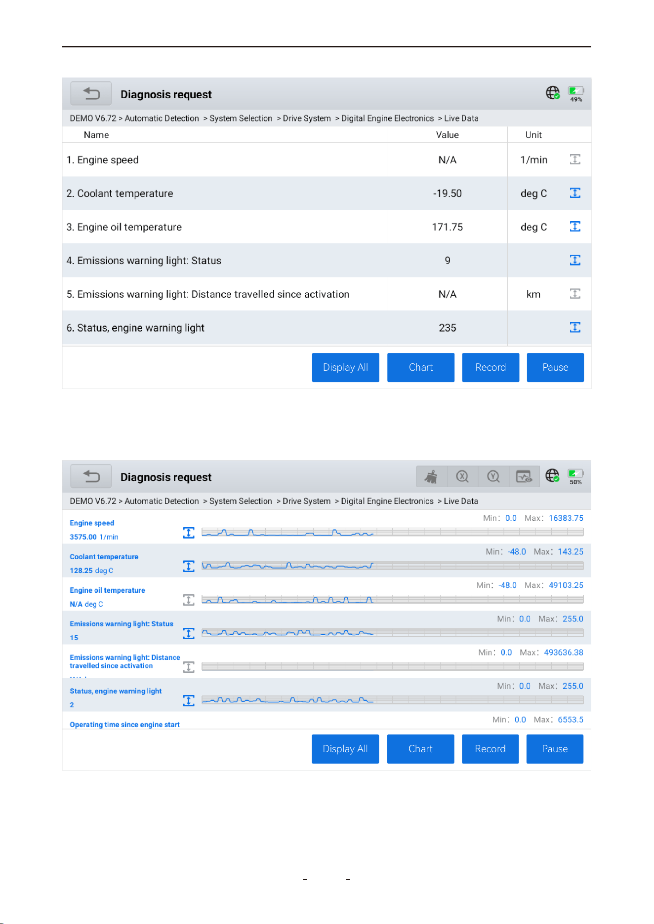
4.12.6 PID Data
Displays real-time PID data from vehicle sensors and control modules. View data in list or
graph formats, set custom value thresholds, and monitor up to 8 sensors simultaneously in
list, individual graph, or merged graph views.
4.12.7 PID Data List
Tap the live data function to display a list of PID names and their real-time values, as shown
in the illustration below.
4.12.8 Individual PID Data Graphing
You can select one individual data, like Engine speed, to its graphing by ticking the box on
the left and then tapping Custom.
28
VD70 Lite Diagnostic Tool
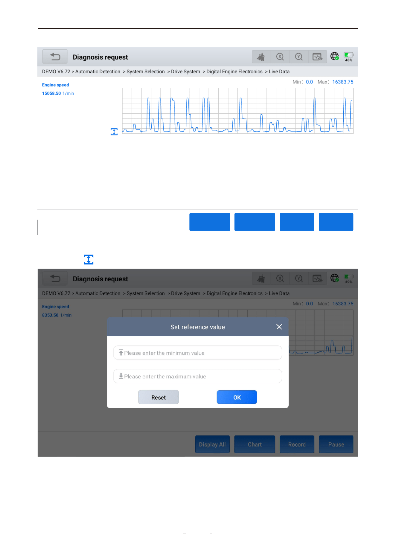
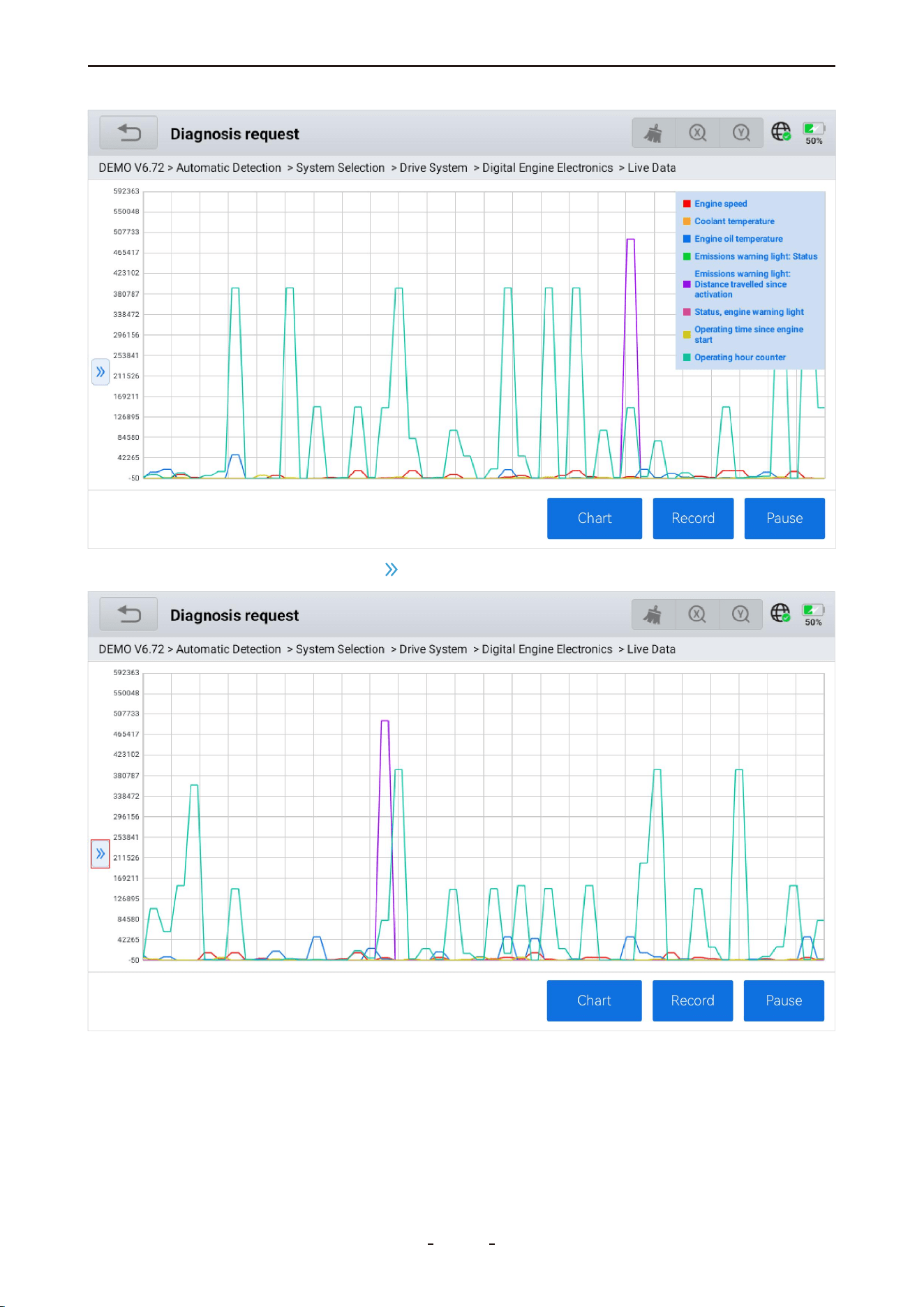
4.12.9 Set Maximum & Minimum Value Alarms
Tap the icon on the left to set value alarms for individual PID data, as shown below.
After setting the values, two red dotted lines will appear on the graph, making it easy to
identify when data exceeds the maximum or drops below the minimum, as illustrated.
29
VD70 Lite Diagnostic Tool
Pause
RecordCha
Display All
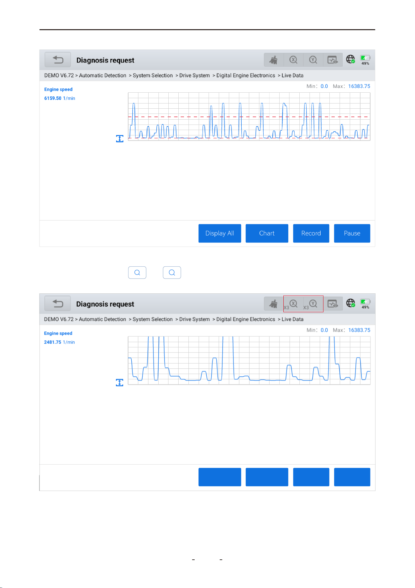
4.12.10 Zoom in or Zoom out
Tap the magnifier icon or to zoom the x-axis or y-axis (up to 3x). Tap again at
maximum zoom to return to the original scale (1x).
30
VD70 Lite Diagnostic Tool
X
Y
Pause
RecordCha
Display All
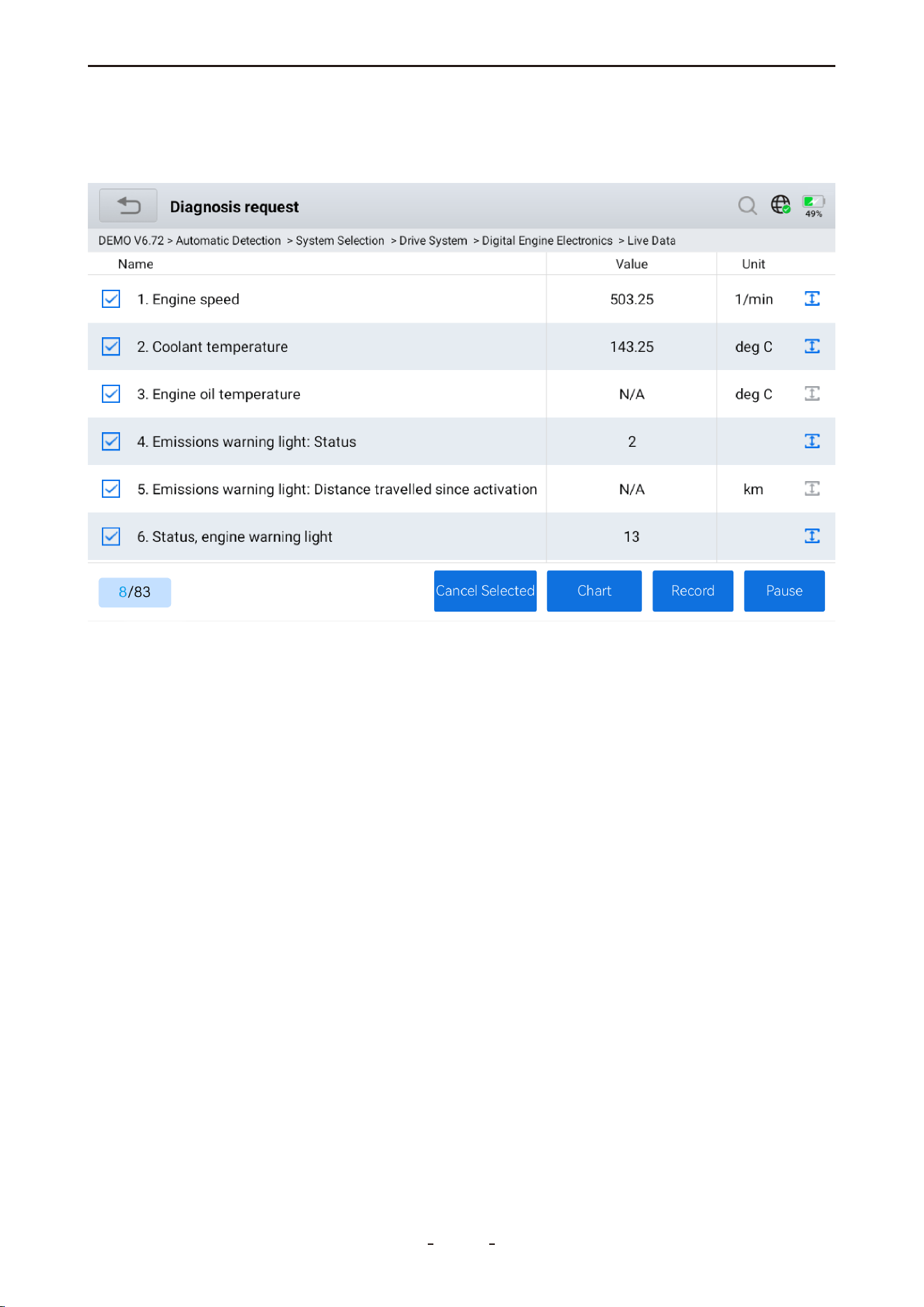
4.12.11 Custom PID Data (Up to 8)
Select up to eight PID data checkboxes and tap Custom to display a custom real-time data
list.
Cancel Selected - Deselects current PIDs for re-selection.
Custom - Displays the custom screen with selected PIDs.
Record - Record data for later playback in Data Playback.
Pause - Halts the continuous retrieval of real-time data.
31
VD70 Lite Diagnostic Tool
4.12.12 Individual Graphing for Up to 8 PIDs
Tap the Graph icon on the custom data list to display individual graphs for up to 8 PIDs on
a single screen, as shown below.
32
VD70 Lite Diagnostic Tool
Display All - Exit and return to the full data list with selections retained.
Graph - View selected PIDs in graph form.
List - View selected PIDs in a data list.
Chart - View selected PIDs in a chart form.
Record - Record data for later playback in Data Playback.
Pause - Halt real-time data retrieval.
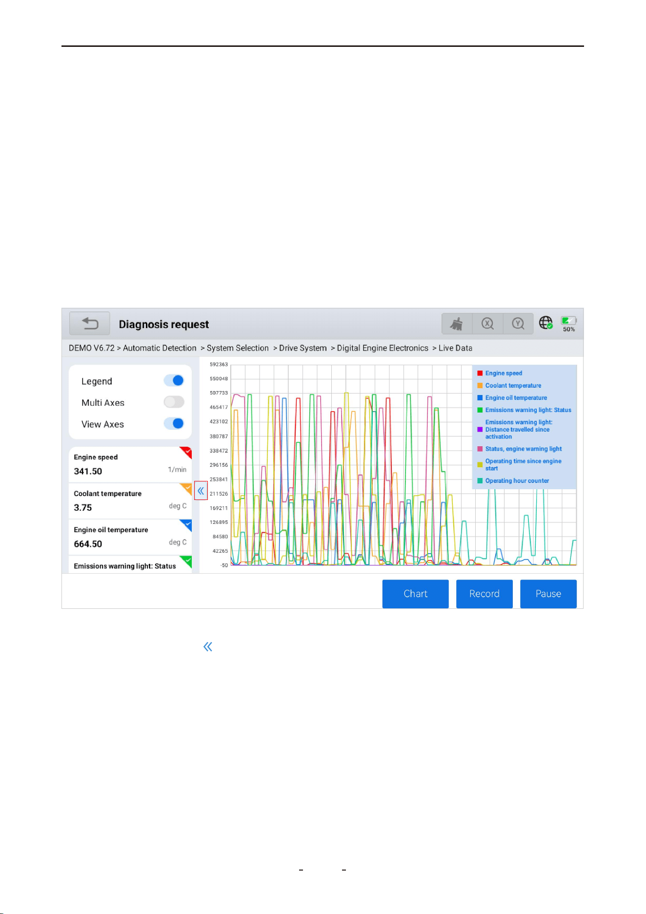
4.12.13 8-In-1 Graphing
Tap the Combine icon to merge up to eight individual graphs into a single view for compar-
ison.
To use this feature:
1. Select up to eight sensor data checkboxes.
2. Tap Custom - Chart - 2D Graph to display the merged graphs on one screen.
4.12.14 Fold/Unfold PID List
Tap the left arrow icon to fold the PID name list, providing a larger view area for the
graphs. Tap again to unfold the list.
33
VD70 Lite Diagnostic Tool
To unfold, tap the right arrow icon to view the PID data names.
34
VD70 Lite Diagnostic Tool
4.12.15 Data Recording
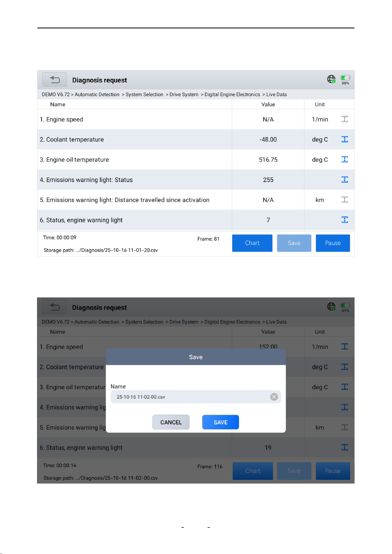
Tap the Record icon to begin recording PID data for later review in Data Playback.
4.12.16 Export Data as CSV
While viewing PID data, tap Record to begin collection, then tap Save to complete. Navi-
gate to Report > CSV View to review the data.
35
VD70 Lite Diagnostic Tool
Frame: 116
Time: 00�00�14
Storage path: .../Diagnosis/25-10-16 11-02-00.csv
Cha
Cha
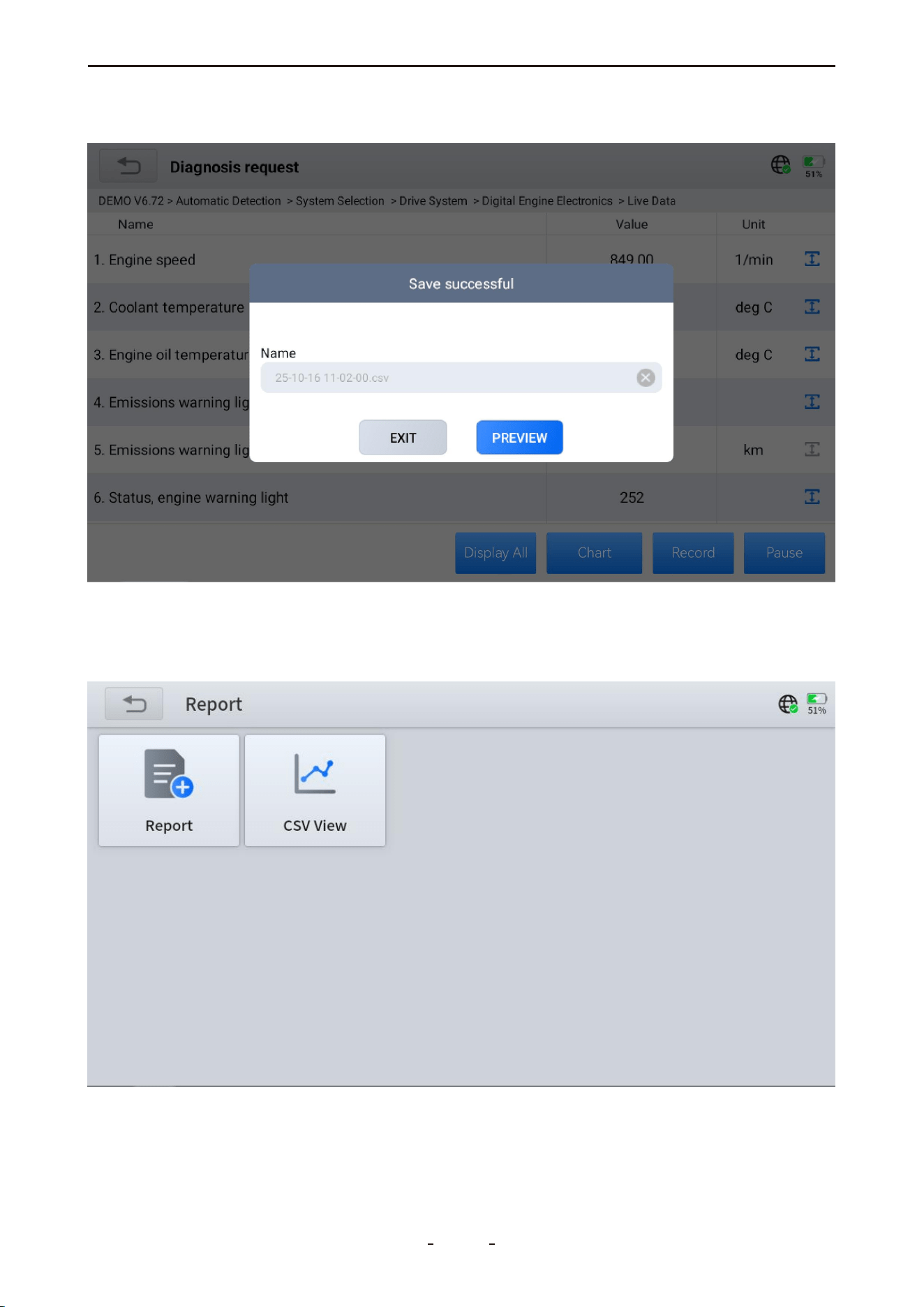
4.12.17 CSV View
After exporting PID data as a CSV file, you can view it by going to the main diagnostic
screen and selectingReport>CSV View.
Tap theCSV Viewicon to display all exported CSV files.
After saving, you can also directly preview it.
36
VD70 Lite Diagnostic Tool
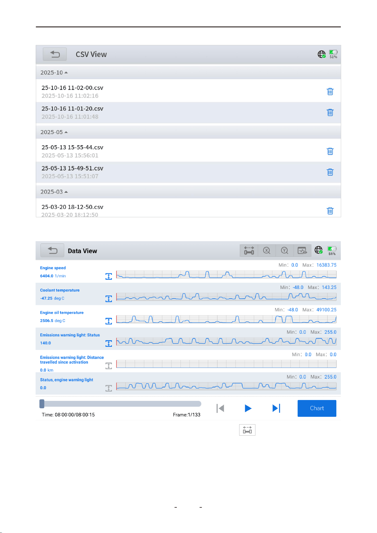
Tap the file to review, and the diagnostic tool will display its contents as shown:
Slide on the timeline in the lower-left corner, or tap the icon in the upper-right corner
to bring up the enlarged timeline, then slide to view real-time PID values in the left column.
37
VD70 Lite Diagnostic Tool
2025-03-20 18:12:50
4.12.18 Export CSV File to a PC
To export recorded CSV files to a computer for storage or further analysis:
1. Connect the diagnostic tool to a PC using the USB Type-C cable.
2. Swipe down from the top of the screen, then select File Transfer mode.
3. On the PC, navigate to:
My Computer → VD70 Lite → Internal Shared Storage → Diagnosis → csv_records
Copy the desired CSV files to your computer.
4.12.19 Share CSV File via Bluetooth
To share a CSV file with an Android tablet or phone:
1. Swipe up to show the toolbar and tap the Home icon.
2. Open ES File Explorer → Local → Home → Diagnosis → csv_records.
3. Press and hold the desired CSV file to select it, then tap More → Share → Bluetooth.
4. Choose the target device to complete the sharing process.
38
VD70 Lite Diagnostic Tool
Note:
CSV files cannot be shared directly from the Android-based diagnostic tool to iOS devices
via Bluetooth.
4.12.20 Freeze Frame
When a fault code is triggered, the vehicle ECU will save related data at that moment to
generate a freeze frame. It is usually used to analyze the root cause that triggers the fault
code, together with fault codes and PID data.
Freeze frame displayed varies across vehicles. Some vehicles may not have the option of
freeze frame which means that the vehicle does not support this function.
39
VD70 Lite Diagnostic Tool
4.12.21 Active Tests (Bi-Directional Controls)
Active tests, also referred to as bi-directional controls, verify the operation of specific actua-
tors—including solenoids, valves, and relays.
4.12.22 Exiting Diagnostics
The diagnostic session remains active while communication with the vehicle is maintained.
To exit diagnostics and power off the tool, the communication link must be properly termi-
nated. A warning message will appear if an attempt is made to shut down during active
communication.
Note:
Disrupting communication during testing may cause damage to the vehicle's electronic
control module (ECU). Always ensure the main cable remains securely connected through-
40
VD70 Lite Diagnostic Tool
out the process. Exit all tests before disconnecting the cable or turning off the diagnostic
tool.
4.12.23 How to Exit
To safely end the session, either use the on-screen back button to return to the main menu,
or close the diagnostic application to terminate communication and exit.
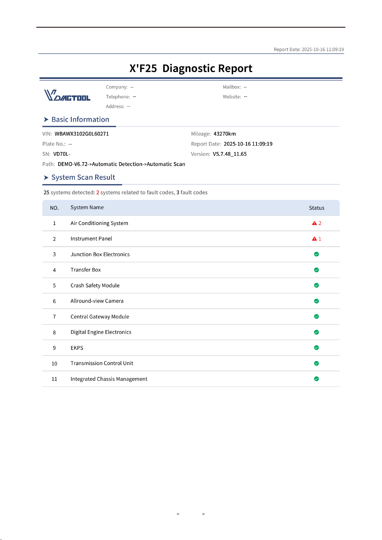
4.13 Full System Diagnostic Report
After completing diagnostics and returning to the main diagnostic screen, enter the VIN,
mileage, and model year in the report generation form, then tap OK to create a diagnostic
report for review or sharing.
To distinguish it from reports generated via vehicle scan or Auto Scan, this type is specifical-
ly referred to as a Full System Diagnostic Report.
To access generated reports, go to Report on the main diagnostic screen and select Diag-
nosis Report. All reports are organized by date and time. Tap any report to view details, or
use Share by E-mail to send it via email, or Print PDF Report to print.
The report summarizes: the total number of vehicle systems detected, how many are affect-
ed by fault codes, the total fault codes found, and which systems are fault-impacted. A
sample Full System Diagnostic Report is shown below.
41
VD70 Lite Diagnostic Tool
4.14 Fault Code Report
Another way to generate a diagnostic report is through the Vehicle Scan / Auto Scan results.
After scanning all available electronic control modules, a "Generate Report" option appears
at the bottom. This produces a simplified diagnostic report showing only the retrieved fault
codes and the affected vehicle systems.
We call this the "Fault Code Report" to distinguish it from the full "Full System Diagnostic
Report". A typical example is shown below:
42
VD70 Lite Diagnostic Tool
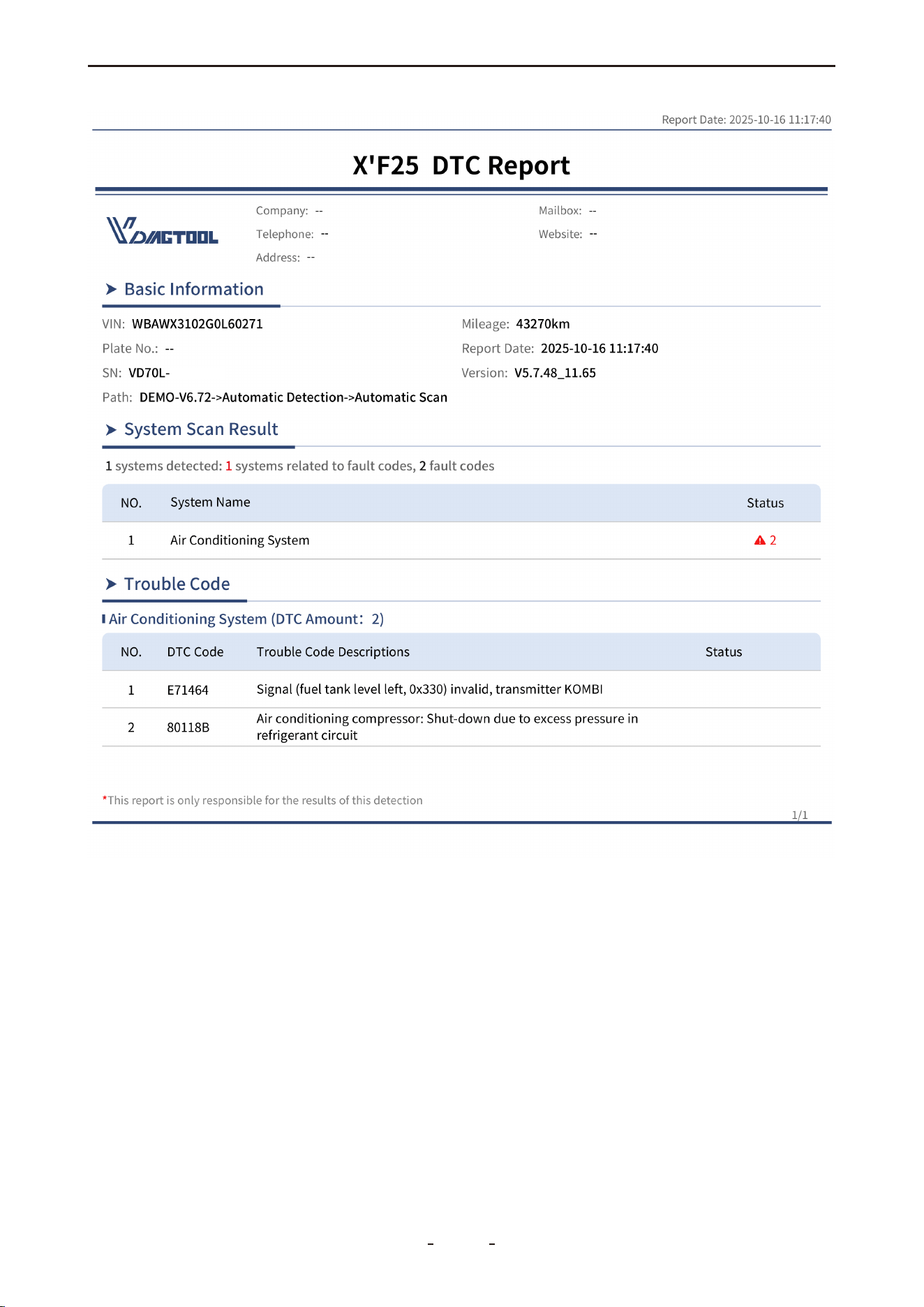
Note:
The diagnostic report generated from the Vehicle Scan / Auto Scan screen—referred to as
the “Fault Code Report”—is designed to display fault codes for quick repair reference. In
contrast, the report generated when exiting the diagnostic menu is a “Full System Diagnos-
tic Report”, which provides a comprehensive overview of the health status of all vehicle
systems.
Both reports are stored in the “Diagnosis Report” section. Note, however, that the reports
themselves are not explicitly labeled as “Full System Diagnostic Report” or “Fault Code
Report” to distinguish between them.
43
VD70 Lite Diagnostic Tool

4.15 Diagnostic Speed
The diagnostic tool supports fast scanning and diagnostics of all vehicle modules. However,
the time required to complete a full scan and diagnosis varies depending on the vehicle.
Key factors affecting diagnostic speed include the vehicle's communication protocol and
the number of installed control modules.
In general, the tool performs faster scans on vehicles using newer communication protocols
compared to older ones. For example, a vehicle using the CAN bus protocol will be scanned
more quickly than one using the older ISO 9141 protocol. Additionally, scanning a modern
vehicle with numerous control modules takes longer than scanning a simpler vehicle with
only a few modules.
4.16 Integrated Modules
In some cases—particularly in older vehicle models—manufacturers may integrate two or
more electronic control systems into a single module. This integration can sometimes cause
confusion during diagnostics.
Below are two common examples:
Powertrain Control Module (PCM): Combines the Engine and Transmission control
systems.
Brake Control Module (BCM): Integrates the ABS and EPB systems.
For instance, that if no dedicated “Transmission” menu is available, transmission-related
data—such as transmission oil temperature—can typically be found under the PID data
section of the Powertrain Control Module. Similarly, functions like ABS bleeding should be
accessed via the Special Function menu within the Brake Control Module.
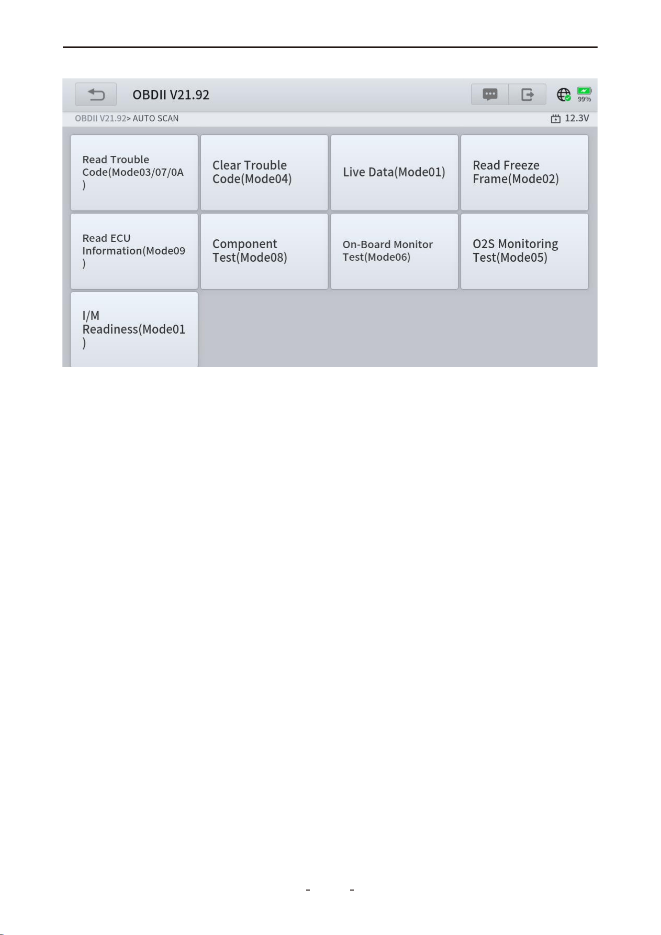
5. OBDII/EOBD
This chapter introduces the concept, protocols, test functions, and basic operations of the
OBDII/EOBD feature. To access this function, navigate to:
MANUAL DIAGNOSIS → Region Selection → OBDII
OBDII/EOBD provides a fast way to:
● Retrieve DTCs and determine the cause of an illuminated Malfunction Indicator Lamp
(MIL)
● Check monitor status before emissions tests
● Verify repairs and perform other emissions-related services
The OBDII function enables access to “generic” OBDII/EOBD data, which is limited to emis-
sions-related diagnostics, including:
● Reading emissions-related Diagnostic Trouble Codes (DTCs)
● Identifying the cause of an illuminated MIL
● Checking monitor status prior to emissions certification testing
44
VD70 Lite Diagnostic Tool
To access additional electronic control module (ECU) data—including vehicle-specific
systems, parameters, or enhanced diagnostics—use AUTO SCAN or MANUAL DIAGNOSIS
to enter all-systems or individual-system diagnostics.
The OBDII/EOBD function is designed to retrieve “generic” OBDII/EOBD data from compli-
ant vehicles. This data is separate from the content available in all-systems or individu-
al-system diagnostics.
IMPORTANT:
Generic OBDII/EOBD data is not included in engine system diagnostic data.
5.1 OBDII Protocols
Global OBD uses the following five communication protocols:
● SAE J1850 PWM
● SAE J1850 VPW
● ISO 14230-4 (KWP2000)
● ISO 9141-2
● ISO 15765-4 / SAE J2480
5.2 Basic Operations
To access generic OBDII/EOBD data, follow these steps:
1. Select MANUAL DIAGNOSIS on the main diagnostic screen.
2. Choose the region of the vehicle manufacturer.
3. Click the OBDII icon next to DEMO.
45
VD70 Lite Diagnostic Tool
OK
5.3 Auto Scan & Protocol Selection
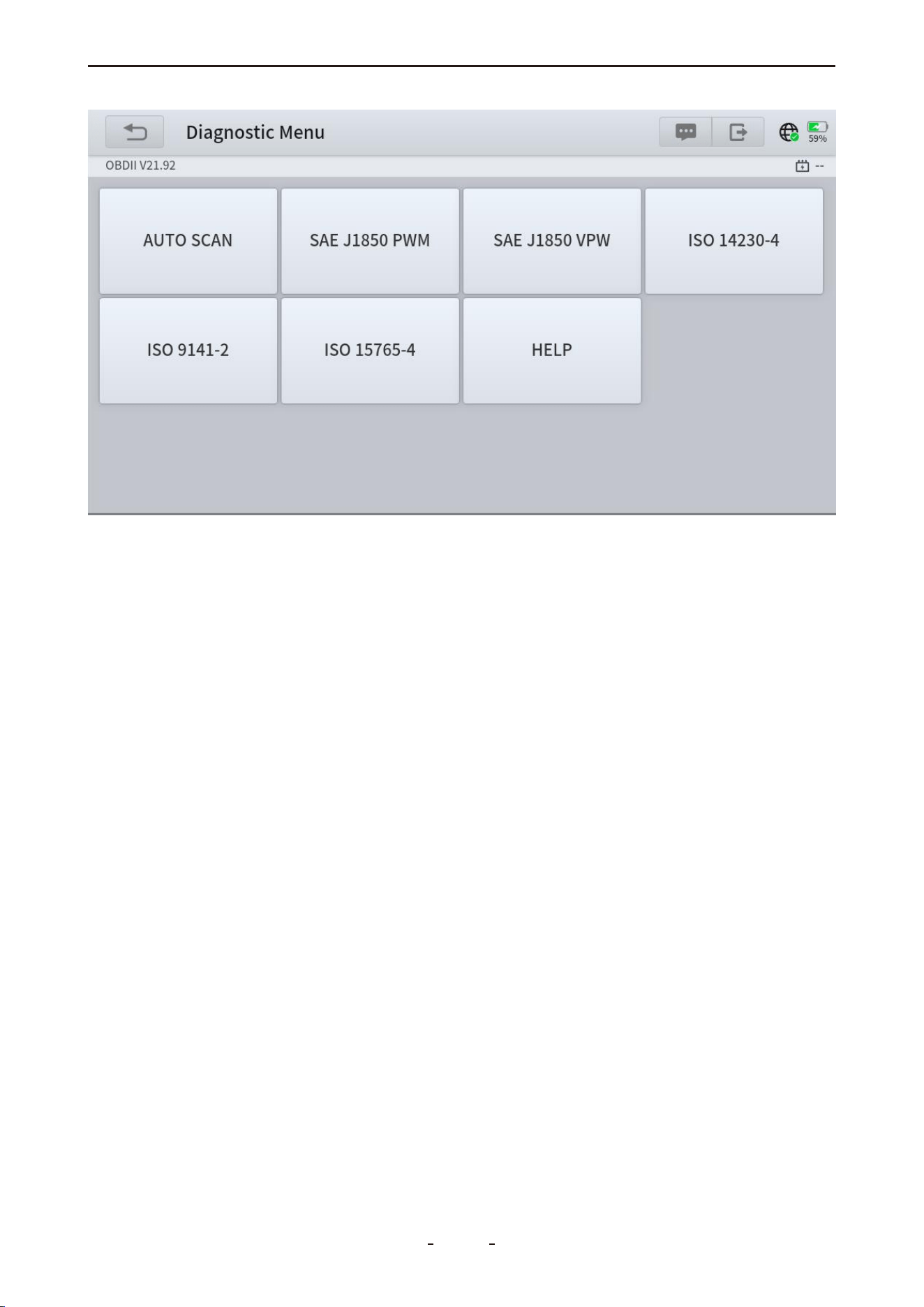
There are two methods to access OBDII/EOBD data from the connected vehicle:
5.3.1 Auto Scan
When this option is selected, the diagnostic tool automatically attempts to communicate
using each available protocol to identify the one utilized by the vehicle.
5.3.2 Protocol Selection
A communication protocol is a standardized method for data exchange between an ECM
and the diagnostic tool. If the vehicle’s protocol is known, you can manually select it to
establish a direct connection.
5.3.3 Help
This section provides support information, including DLC location, a DTC library, common
abbreviations, and background details such as OBDII modes.
46
VD70 Lite Diagnostic Tool
5.4 10 Modes of OBDII
Mode $01 – Live Data
Mode $02 – Freeze Frame Data
Mode $03 – Stored Trouble Codes
Mode $04 – Clear/Reset Emission-Related Data
Mode $05 – Oxygen Sensors Test Results
Mode $06 – On-Board System Tests Results
Mode $07 – Pending Trouble Codes
Mode $08 – Control On-Board Systems
Mode $09 – Vehicle Information
Mode $0A – Permanent Trouble Codes
5.5 OBDII/EOBD Menu
5.5.1 Read Trouble Code
This option displays a list of current emission-related DTCs, including:
● Stored Codes (Generic and Manufacturer-Specific)
● Pending Codes
● Permanent Codes
47
VD70 Lite Diagnostic Tool

5.5.1.1 Stored Codes
Stored DTCs are active fault codes that are stored in the vehicle's ECU when the onboard
diagnostic system confirms a problem. These codes will typically illuminate the check
engine light (MIL) immediately upon detection. Current DTCs can be cleared using the diag-
nostic tool's erase function, though some may clear automatically after several prob-
lem-free drive cycles if the issue doesn't recur.
5.5.1.2 Pending Codes
Pending DTCs are temporary fault codes stored when a potential issue is first detected by
your vehicle's monitoring systems. Unlike regular trouble codes, these won't turn on the
check engine light immediately. The system keeps them as a warning - if the problem hap-
pens again on your next drive, they'll turn into confirmed trouble codes and activate the
warning light. You can clear these pending codes with your diagnostic tool, or they'll disap-
pear automatically if the issue doesn't recur after several driving cycles.
These codes are useful for spotting intermittent problems early or checking if a repair fixed
an issue.
5.5.1.3 Permanent Codes
Permanent DTCs are fault codes that were severe enough to originally trigger the check
engine light (MIL), and remain stored in the vehicle's computer even after the light turns off.
These codes preserve a record of the fault whether the MIL was cleared manually or
stopped illuminating because the problem didn't reoccur. They automatically erase only
after: (1) the underlying issue is fully repaired, and (2) the system successfully completes 3
consecutive drive cycles without detecting the fault.
5.5.2 Generic & Manufacturer-Specific Codes
Code Definitions
Diagnostic Trouble Codes (DTCs) are used by OBDII systems to identify and communicate
issues within the vehicle. The first character of a DTC indicates whether it is a generic code
(applicable to all OBDII systems) or a manufacturer-specific code. The remaining three char-
acters specify the affected system and circuit.
Generic Codes: DTCs with the second character as “0” are generic codes.
Manufacturer-Specific Codes: DTCs with the second character as “1” are specific to the
vehicle manufacturer.
48
VD70 Lite Diagnostic Tool
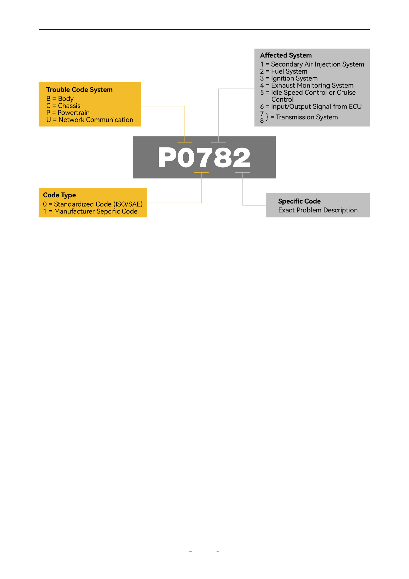
5.5.2.1 First DTC Character
The first character of a DTC is always a letter, indicating the general system where the fault
is located. There are four types of codes:
● P Codes: Powertrain – issues related to the engine, transmission, drivetrain, or fuel system.
● C Codes: Chassis – problems in mechanical systems outside the passenger compartment,
such as steering, suspension, or braking.
● B Codes: Body – faults in components within the passenger compartment area.
● U Codes: Network – problems with the vehicle's onboard computer systems or communi-
cation integration functions managed by OBD.
5.5.2.2 Second DTC Character
The second character in a DTC is a numeric digit—either “0” or “1”—that indicates the
code's definition source:
0: Indicates a standard SAE international code (also called a generic code), applicable to all
OBDII-compliant vehicles.
1: Represents a manufacturer-specific code (also referred to as an enhanced code), unique
to the vehicle's make or model. For further details on such codes, consult the vehicle manu-
facturer directly.
5.5.2.3 Third DTC Character
If the second character is “0” (indicating a generic code), the third character specifies the
malfunctioning subsystem. The values are defined as follows:
0: Fuel and air metering and auxiliary emission controls
1: Fuel and air metering injection system
2: Fuel and air metering (injection system)
3: Ignition systems or misfires
4: Auxiliary emission controls
5: Vehicle speed control, idle control systems, and auxiliary inputs
6: Computer output circuit
7-8: Transmission
49
VD70 Lite Diagnostic Tool
5.5.2.4 Fourth and fifth DTC Characters
The fourth and fifth characters of a DTC form a two-digit number ranging from 00 to 99,
known as the “Specific Fault Index.” This value identifies the exact nature of the malfunction.
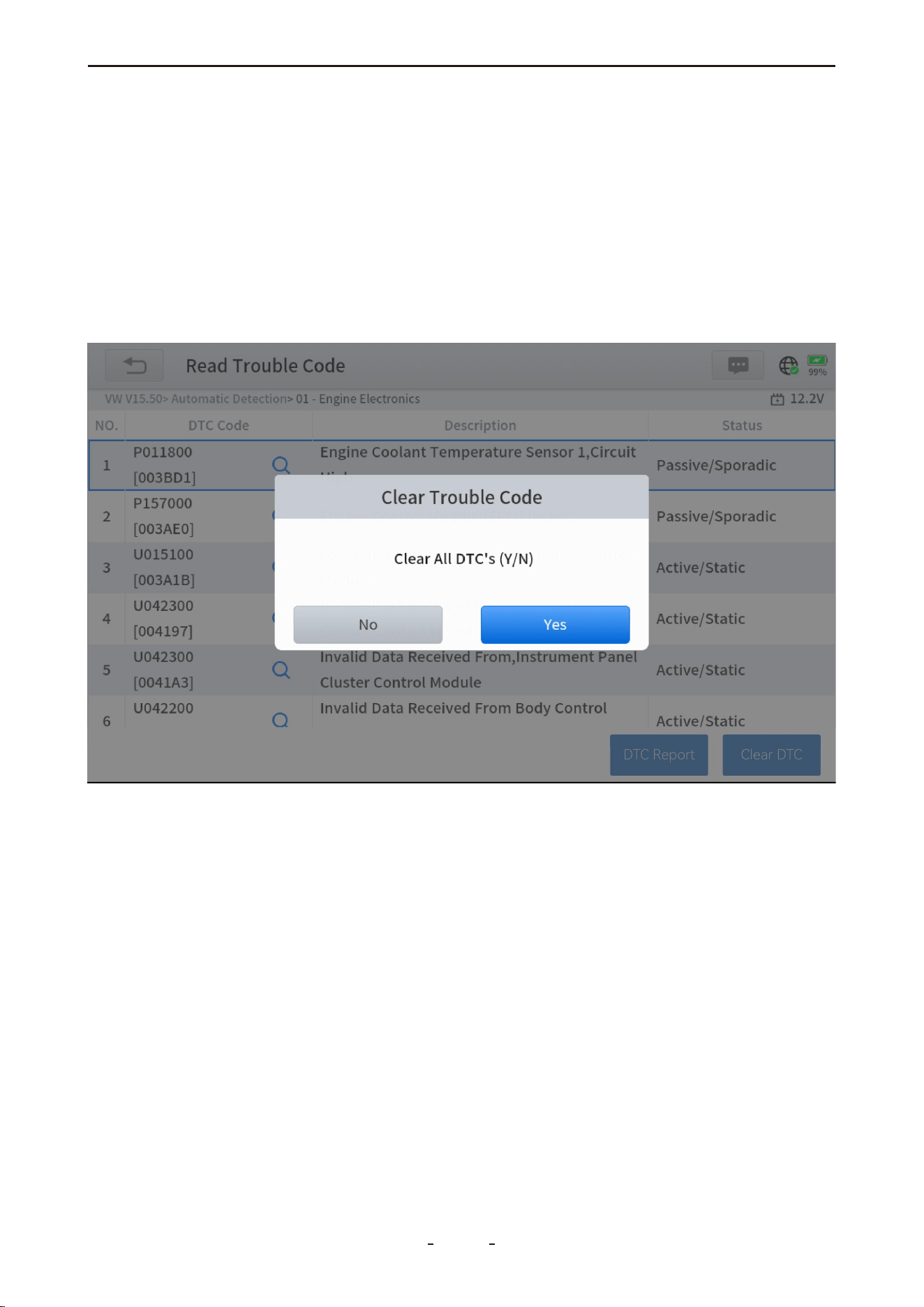
5.5.3 Clear Trouble Code (Mode $04)
This function clears all emission-related diagnostic data—including DTCs, freeze frame
data, and test results—from the selected ECM's memory. Although OBDII/EOBD only
displays generic data, clearing codes will erase all stored information, including enhanced
codes and freeze frames.
A confirmation screen will appear to prevent accidental data loss. Select Yes to proceed.
5.5.4 Live Data (Mode $01)
This function displays real-time emission-related data from the selected electronic control
module (ECM). The data is displayed in two columns: the left column shows parameter
descriptions, and the right column displays the corresponding values, units, or states.
5.5.5 Read Freeze Frame (Mode $02)
Freeze frame data captures a "snapshot" of key parameter values at the moment a DTC is
triggered. This function displays freeze frame data for stored emission-related DTCs. Typi-
cally, the stored frame corresponds to the most recent DTC. However, higher-priority
DTCs—those with greater impact on emissions—may overwrite previous records, ensuring
the most critical data is retained.
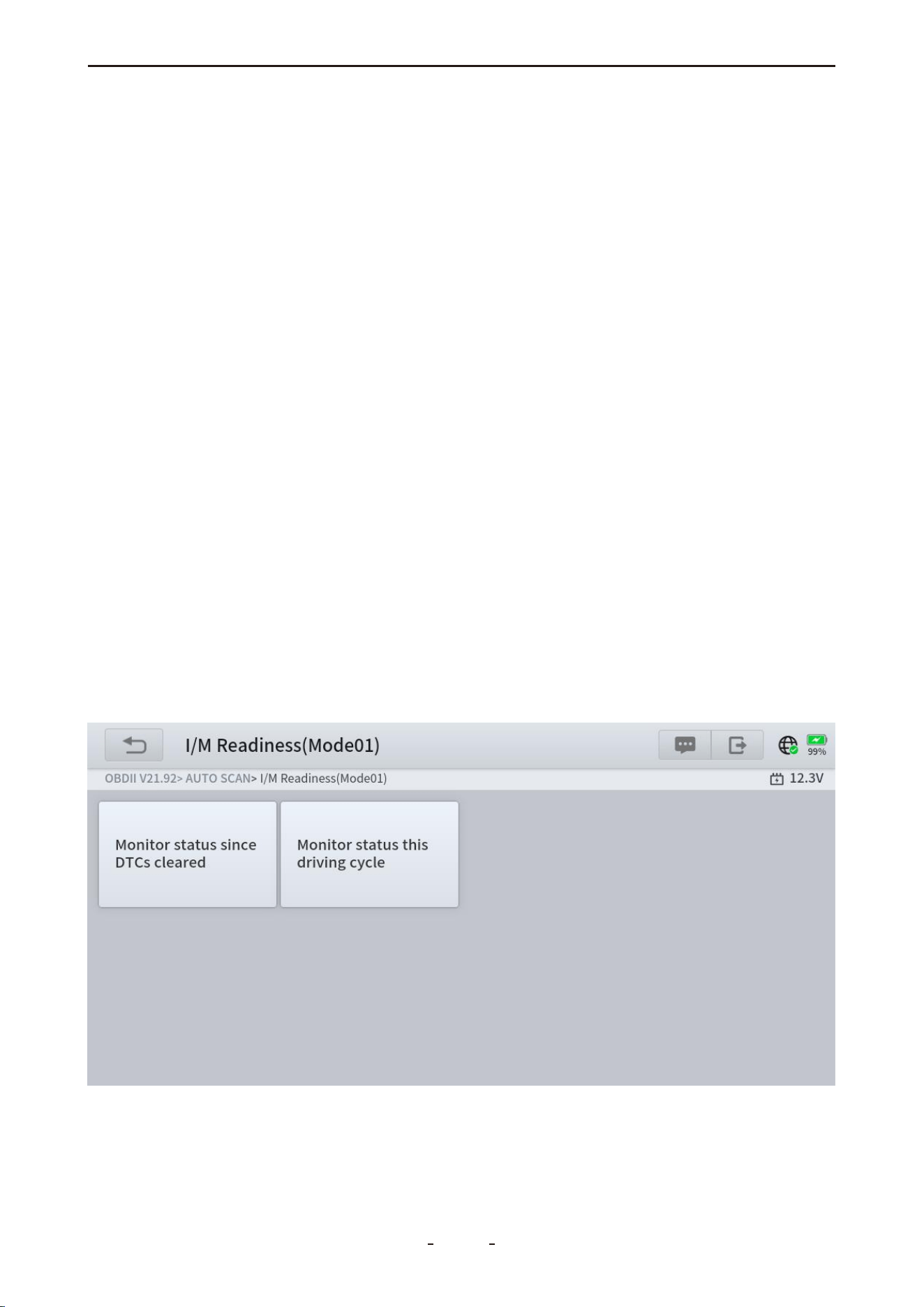
5.5.6 I/M Readiness (Smog Check)
This function checks the status of the vehicle's emission monitoring system, making it ideal
for pre-inspection before state emissions tests. Selecting I/M Readiness opens a sub-menu
with two options:
50
VD70 Lite Diagnostic Tool
31%
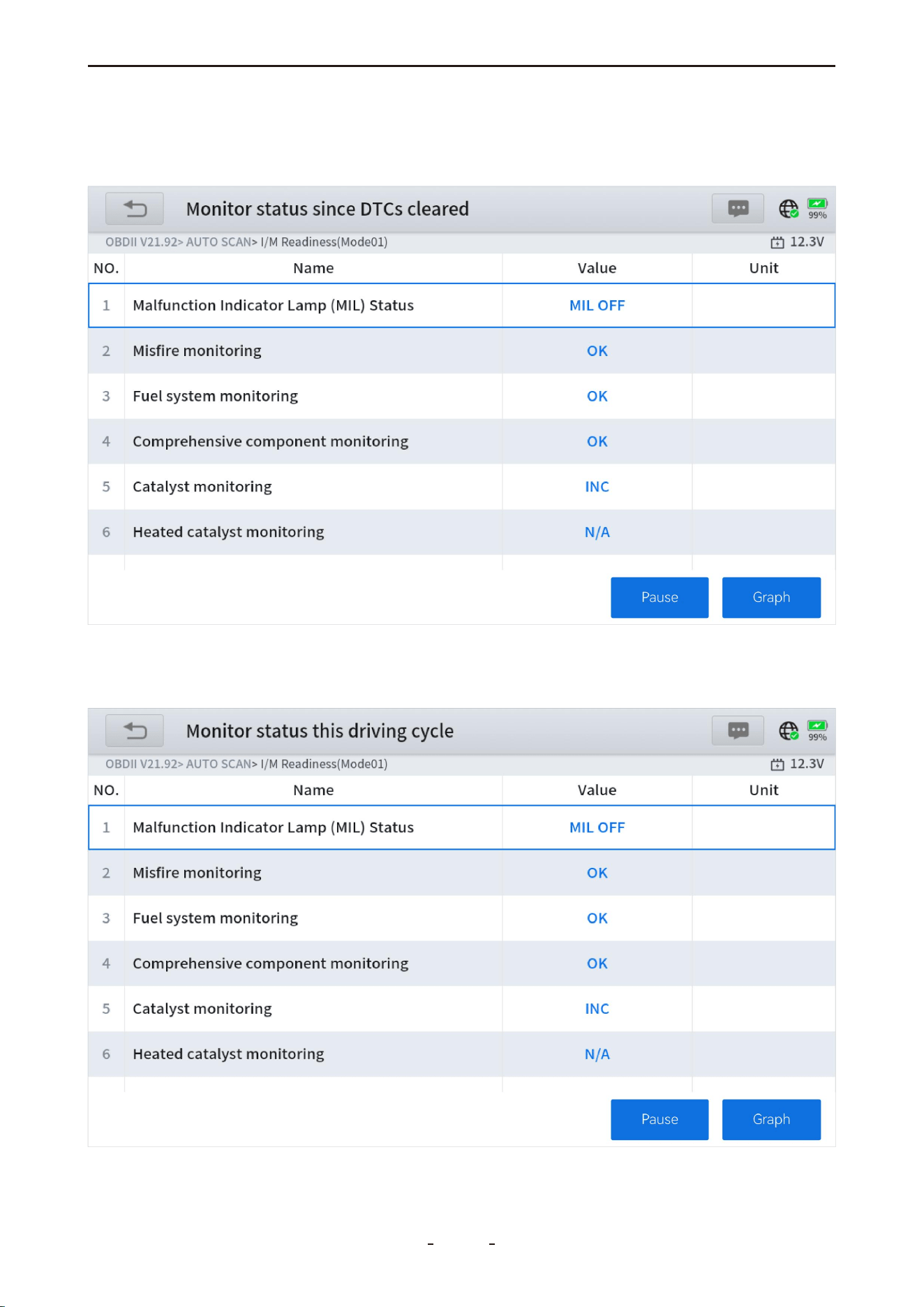
5.5.6.1 Since DTCs Cleared
Displays the status of emission monitors since the last time diagnostic trouble codes were
cleared.
5.5.6.2 This Driving Cycle
Displays the status of emission monitors since the start of the current driving cycle.
51
VD70 Lite Diagnostic Tool

5.5.7 O2S Monitoring Test (Mode $05)
This function provides a menu of tests to evaluate the integrity of oxygen sensors. Selecting
a test displays all relevant O2S parameters, with the test identification (ID) shown at the top
of the data list.
5.5.8 On-Board Monitor Test (Mode $06)
This function displays the results of On-Board Monitor tests, which are particularly useful
after performing vehicle service or clearing control module memory.
A menu of available test results for monitored systems is provided, covering both continu-
ously monitored components (e.g., misfire counters) and non-continuous monitors. Select
a test to view its results.
52
VD70 Lite Diagnostic Tool

5.5.9 Component Test (Mode $08)
This function enables limited bidirectional control of the ECM, allowing the diagnostic tool
to operate specific systems, tests, or components—such as initiating an EVAP leakage test.
It is useful for verifying whether the ECM responds correctly to commands.
5.5.10 Read Vehicle Information (Mode $09)
This function allows the diagnostic tool to request and display vehicle-specific information,
such as the VIN, calibration identification, and CVN.
IMPORTANT:
Not all vehicles support every service mode. Available menu options may vary.
6. Special Functions & Maintenance Services
This chapter introduces various scheduled service and maintenance functions, also referred
to as “Special Functions”. These functions are typically presented as a series of menu-driven
executable commands. By following the on-screen instructions—selecting appropriate
options, entering correct values, and performing necessary actions—you will be guided
through the complete process of executing each function.
Since vehicle configurations vary by model, specific operation steps for each function are
not listed here. In general, please follow the prompts displayed on the tool screen.
For further assistance, please contact our support team at [email protected] and
provide the device serial number, vehicle VIN, and the required function.
6.1 Oil Reset
The diagnostic tool allows you to reset the engine oil life system, which estimates the opti-
mal oil change interval based on driving conditions and climate. The oil life reminder must
be reset after each oil change so the system can calculate the next service due date.
This function is used in the following scenarios:
● The service lamp is illuminated, indicating required maintenance. After servicing, reset the
mileage or time to turn off the lamp and start a new service cycle.
● After an oil change or replacement of oil life monitoring sensors, the service lamp must
be reset.
Operation Steps:
1. Enter the Oil Reset menu and select the vehicle model.
2. Follow the on-screen instructions specific to the vehicle and press OK after completing
each step.
53
VD70 Lite Diagnostic Tool
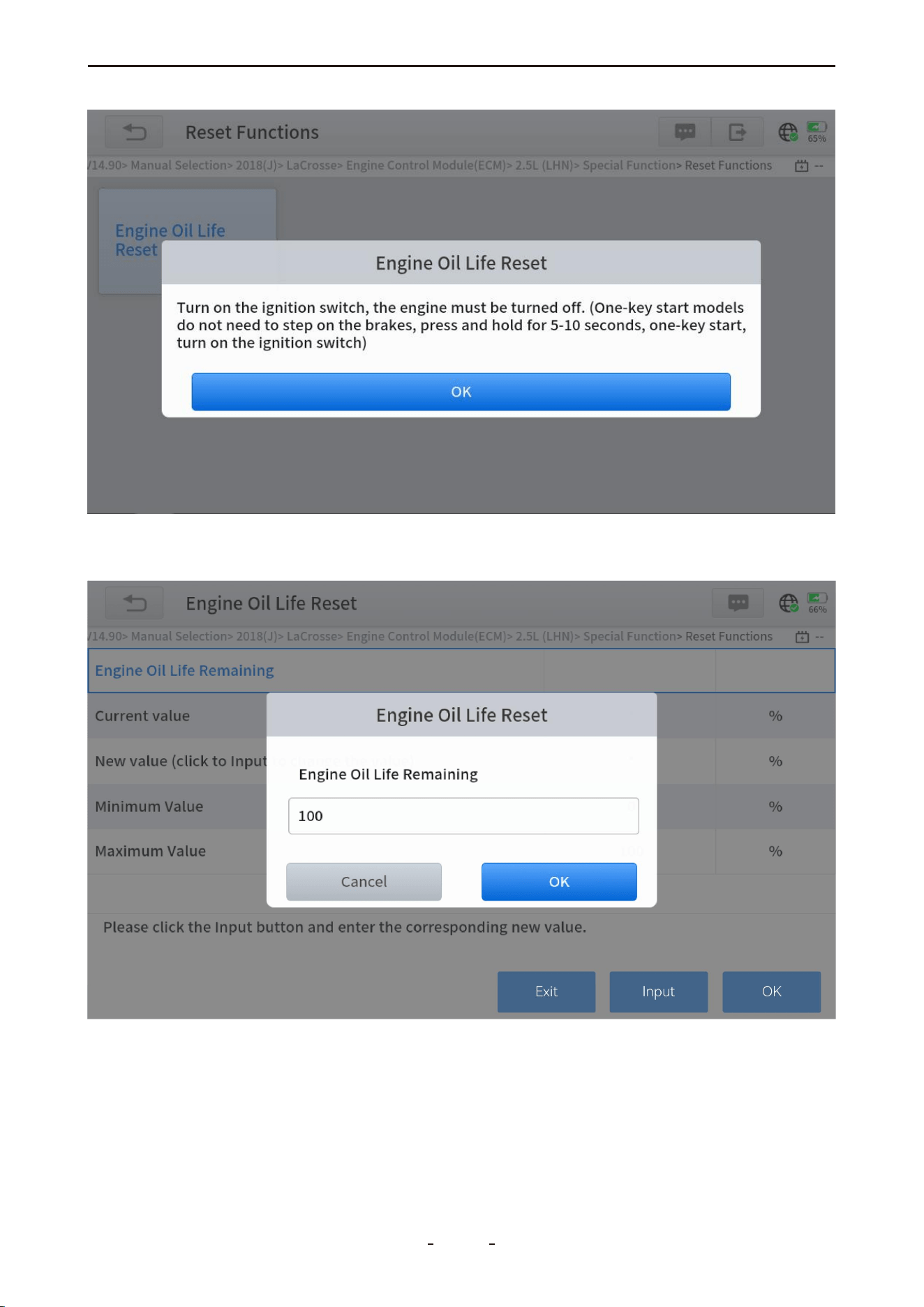
3. Enter the maintenance mileage reset menu.
4. Select INPUT, enter a reasonable value for the remaining oil life, and press OK.
5. Confirm the [New Value] and select OK in the lower right to complete the process.
54
VD70 Lite Diagnostic Tool
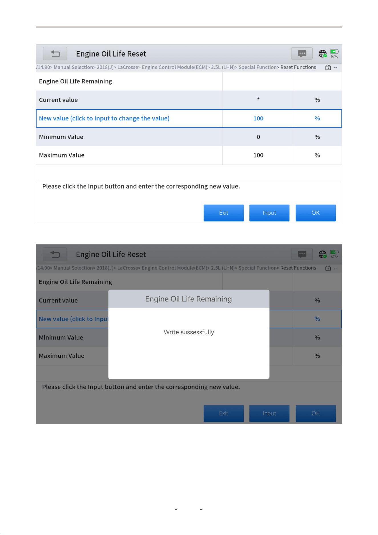
6. A “Write successfully” message will appear upon completion.
55
VD70 Lite Diagnostic Tool
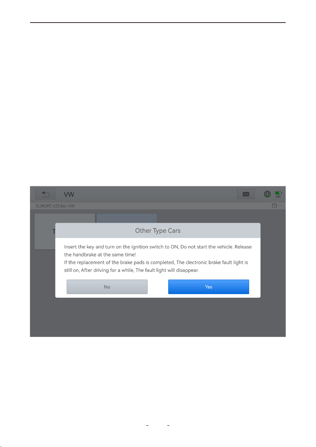
31%
3. Enter Maintenance Mode, release the handbrake, and press OK.
6.2 EPB
The Electronic Parking Brake (EPB) reset function allows you to perform maintenance oper-
ations such as resetting the brake system, retracting or releasing brake pistons, and cali-
brating the G-sensor and vehicle level. It ensures safe and effective servicing of the elec-
tronic brake system, including deactivating/activating control systems, assisting with brake
fluid procedures, and applying/releasing brakes after replacing pads or discs.
Typical Use Cases:
1. After replacing worn brake pads or sensors, a reset is required to clear related fault codes
and prevent false warnings.
2. A reset is also necessary in the following situations:
● The brake pad or wear sensor has been replaced
● The brake pad indicator is illuminated
● The brake sensor circuit is shorted
● The servo motor has been replaced
Operation Steps:
1. Enter the EPB menu and select the corresponding vehicle model.
2. Follow the on-screen instructions and press YES when prompted.
56
VD70 Lite Diagnostic Tool
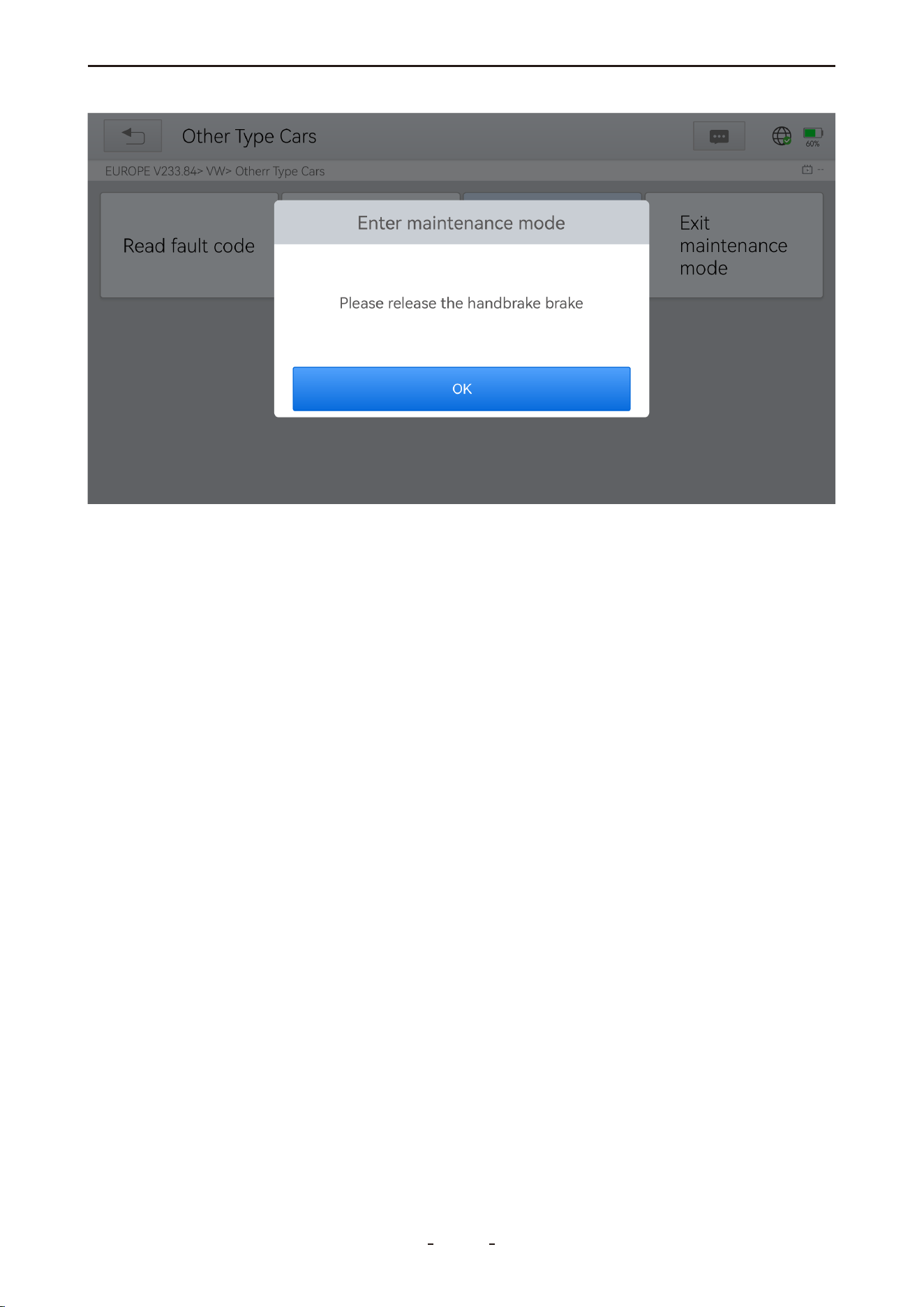
4. Wait for a “Successful operation” message, then press OK.
5. Select Exit Maintenance Mode and confirm upon another success message.
6.3 SAS
Steering Angle Sensor (SAS) calibration permanently stores the current steering wheel posi-
tion as the straight-ahead reference in the SAS EEPROM. Before calibration, ensure the front
wheels and steering wheel are precisely aligned in the straight-ahead position. The VIN is
also read from the instrument cluster and stored in the SAS EEPROM. Upon successful cali-
bration, all SAS fault codes will be cleared automatically.
This procedure establishes the zero reference point for straight-line driving, enabling the
ECU to accurately calculate left and right steering angles.
When to Perform SAS Calibration:
After any of the following services:
● Replacing the steering angle sensor
● Replacing steering mechanical components (e.g., gearbox, column, tie rod, knuckle)
● Performing a four-wheel alignment
● Repairing the vehicle body
Operation Steps:
1. Enter the SAS menu and select the corresponding vehicle model.
2. Choose Set steering angle sensor and follow the on-screen instructions.
57
VD70 Lite Diagnostic Tool
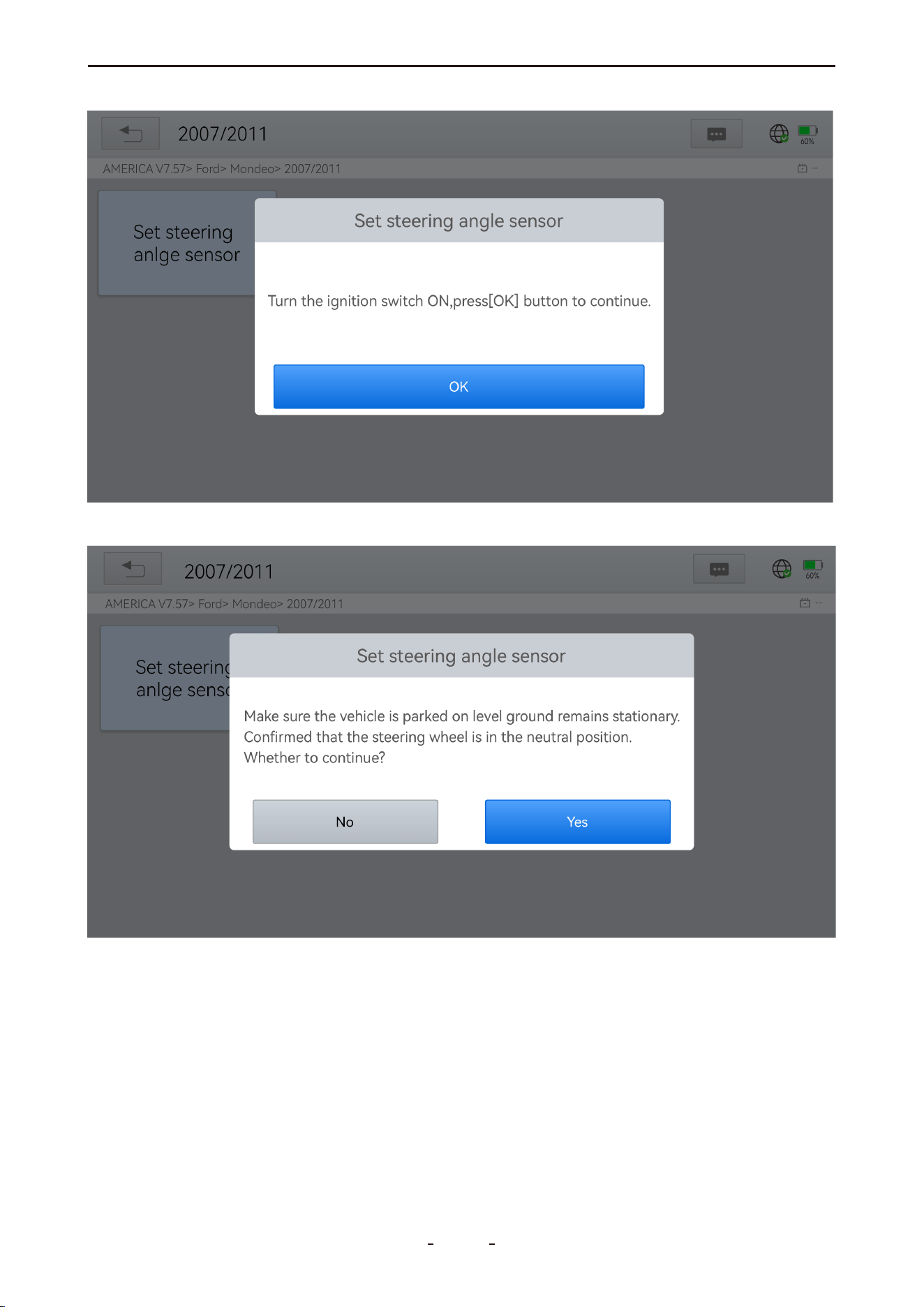
3. When prompted, press OK to proceed.
4. Continue following the instructions and press Yes to confirm.
58
VD70 Lite Diagnostic Tool
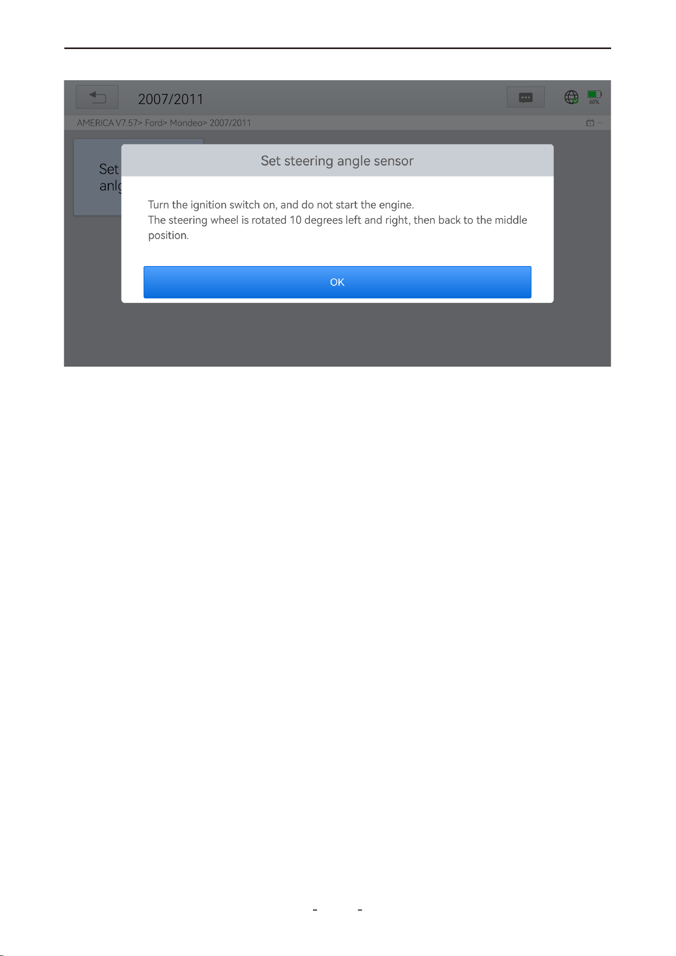
31%
5. Wait for the “Function execution is completed” message to indicate successful calibra-
tion.
6.4 BMS Reset
The Battery Management System (BMS) Reset function enables the diagnostic tool to evalu-
ate the battery state, monitor current, register battery replacement, and activate the vehi-
cle’s rest state. This process clears existing low-battery fault information and performs bat-
tery matching to ensure accurate power management.
When to Perform BMS Reset:
● After replacing the main battery, to clear previous fault data and prevent false detection
by control modules.
● To rematch the control module and monitoring sensor for accurate battery usage track-
ing, avoiding error messages on the instrument cluster.
Failure to reset may disable electric features such as auto start-stop, one-touch sunroof, or
automatic power windows.
Operation Steps:
1. Enter the BMS Reset menu and select the corresponding vehicle model.
2. Turn on the ignition switch.
3. Press OK to continue.
4. Enter the battery capacity (within the specified range) and press OK.
59
VD70 Lite Diagnostic Tool
31%
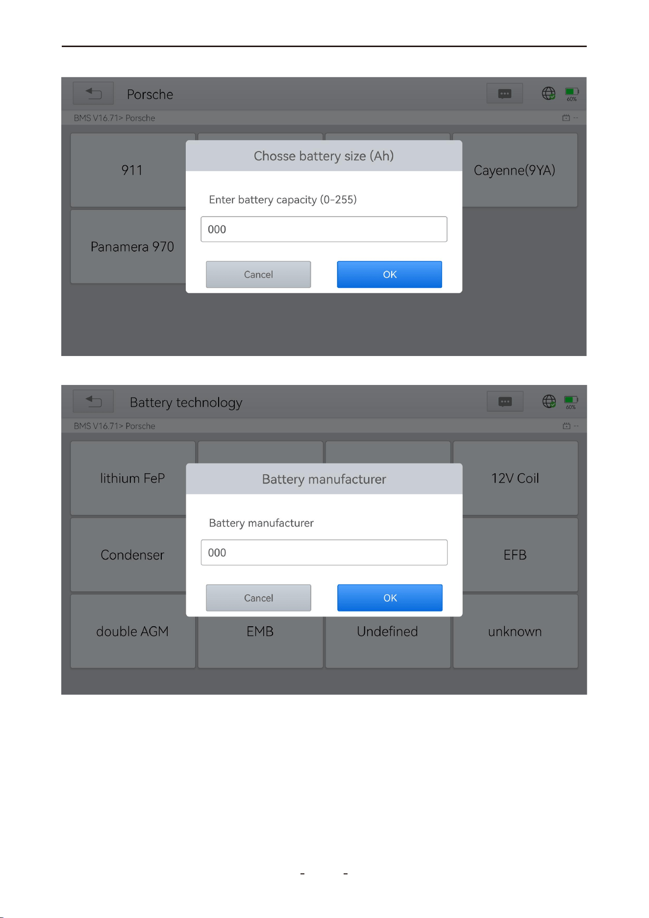
5. Enter the battery manufacturer and press OK.
6. Enter the 10-digit battery serial number and press OK.
60
VD70 Lite Diagnostic Tool
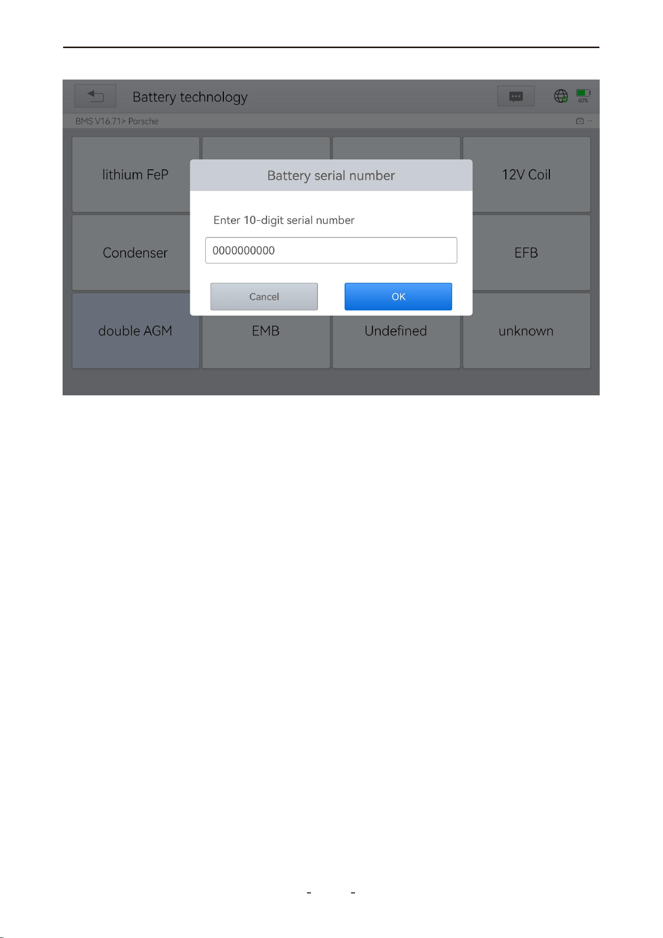
6.5 Injector Coding
This function writes the identification code of a fuel injector into the ECU, enabling the ECU
to recognize and accurately control the new injector.
Injector coding is required after replacing the ECU or an injector to ensure proper cylin-
der-specific fuel injection control. Coding is typically not necessary after cleaning. The injec-
tor identification includes both precision and type values.
When replacing an injector, use a compatible model.
Most modern vehicles support injector coding.
Operation Steps:
1. Enter the Injector Coding menu and select the appropriate chassis model.
2. Choose Fuel Injection Nozzle Injection Volume Adjustment.
3. Read the note carefully and press OK.
61
VD70 Lite Diagnostic Tool
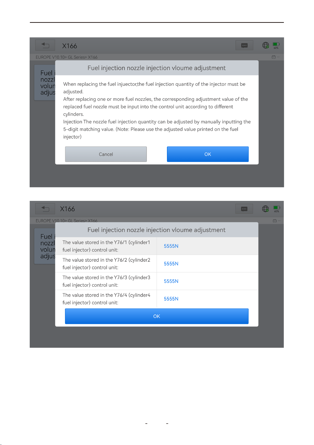
4. Review and confirm the current values stored for each cylinder.
5. For each replaced injector, enter the new 5-digit value and press OK. Wait for the “Write
successfully” message.
62
VD70 Lite Diagnostic Tool
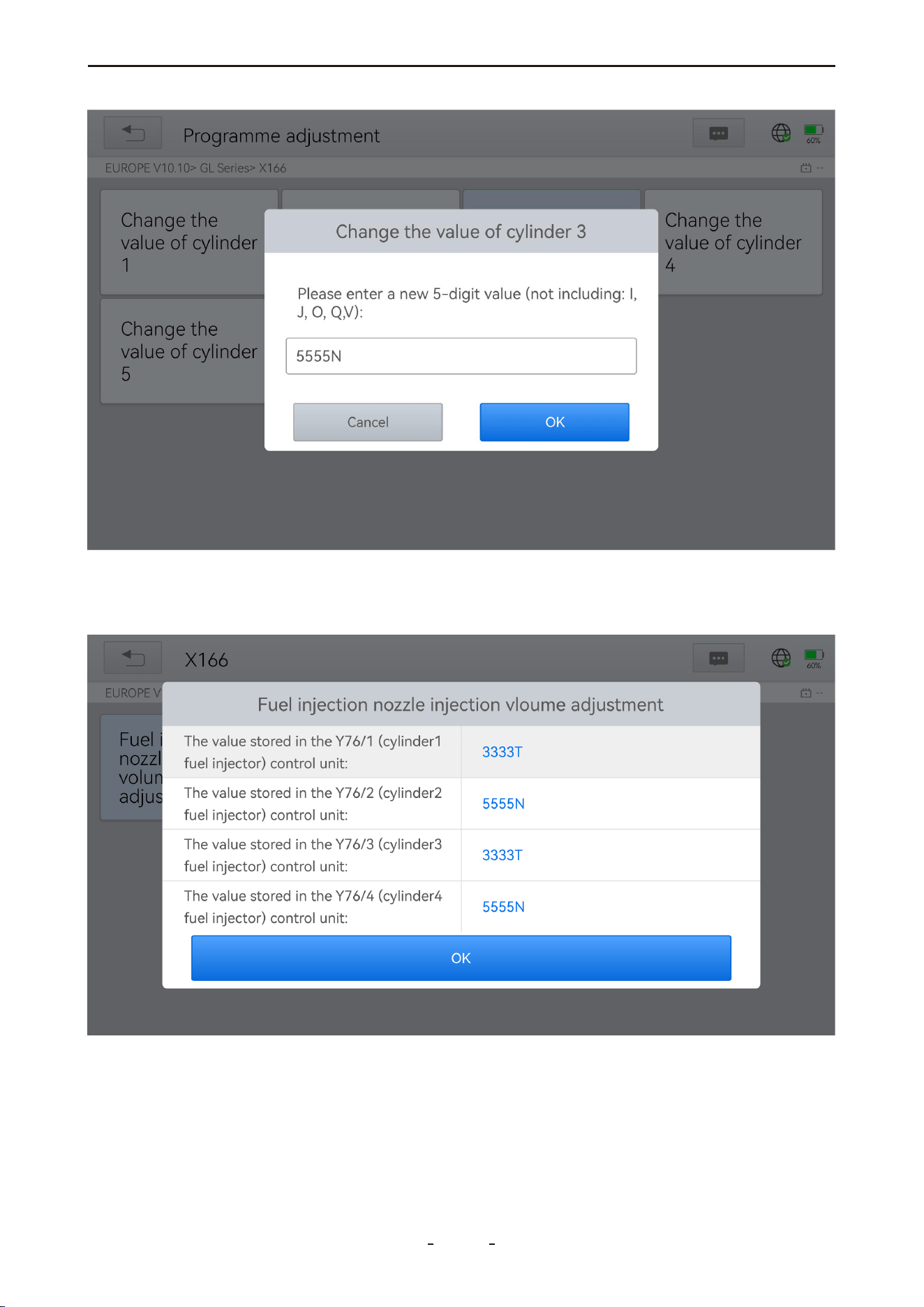
31%
6. Turn off the ignition switch.
7. When prompted, turn the ignition switch back on.
8. Re-enter the adjustment menu to verify the new values.
63
VD70 Lite Diagnostic Tool
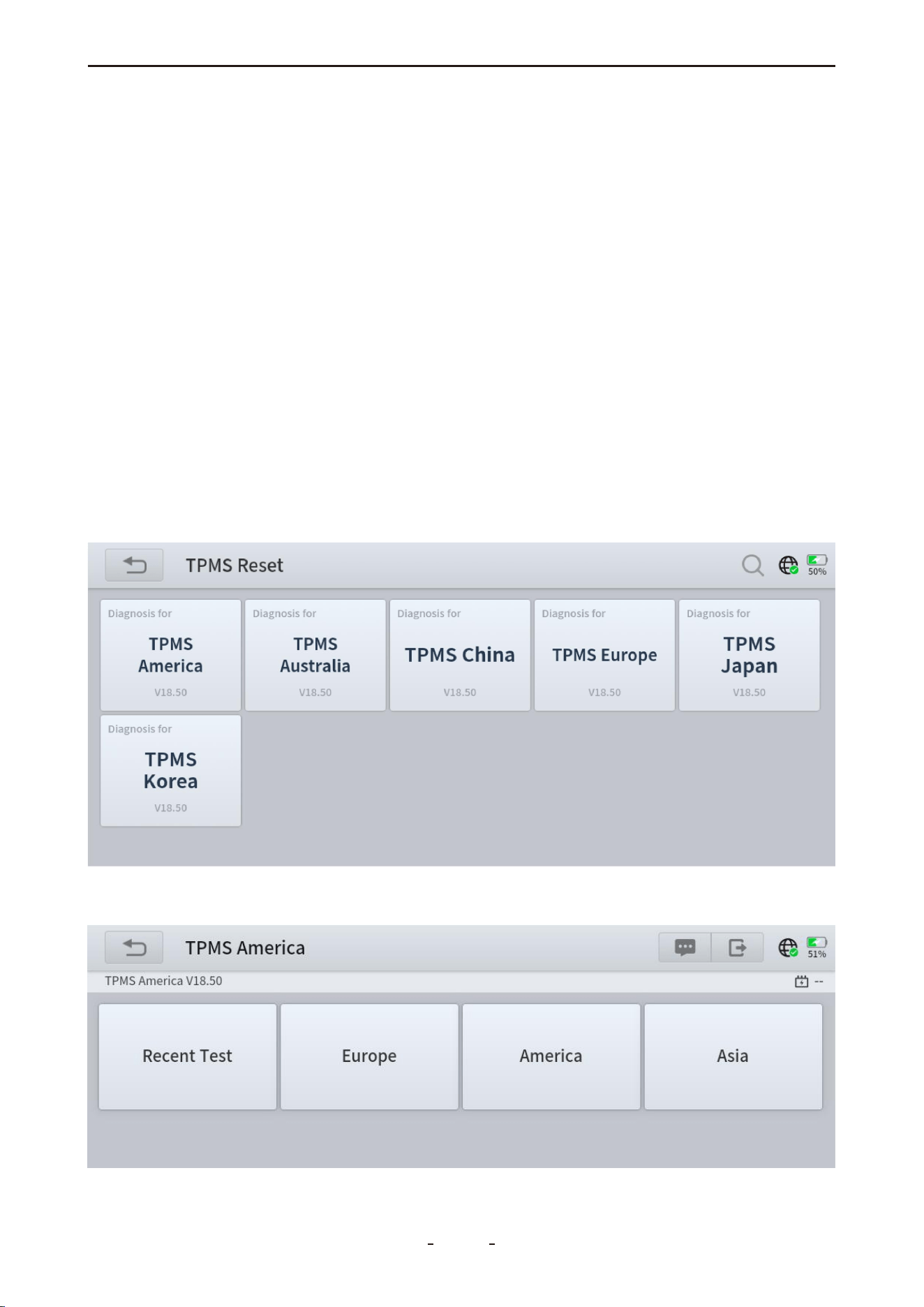
6.6 TPMS Reset
This function supports learning, matching, and resetting operations for tire pressure sen-
sors.
When to Perform TPMS Reset:
● After replacing tires
● When troubleshooting tire pressure-related issues
● When the tire pressure sensor signal is lost
Important Notes:
● Some vehicle models require a TPMS activation tool for sensor matching.
● After resetting, driving for a period may be necessary to clear the fault light.
● Tire pressure imbalance can also trigger the tire pressure warning light.
● This function only works with pre-activated sensors. For new sensors, use a professional
TPMS tool.
Even for the same vehicle model, the tire pressure monitoring system may vary depending
on the region of manufacture. To accommodate these differences, the TPMS Reset function
provides six regional sub-menus covering major automotive manufacturing regions: Korea,
Japan, USA, China, Australia, and Europe.
Select the sub-menu matching the vehicle's region of origin, then choose the specific
model to continue.
64
VD70 Lite Diagnostic Tool

TPMS reset can be categorized into four methods—Automatic Relearn, Static Relearn, Copy
ID, and OBD Relearn—depending on the specific vehicle model. Even when the relearning
methods share the same name, the actual procedures may vary.
● Automatic Relearn
1. Install the tire pressure sensors correctly.
2. Adjust all tire pressures to the specified values.
3. Keep the vehicle stationary for over 20 minutes (engine and power off).
4. Drive at 30–100 km/h for more than 15 minutes.
5. The system will automatically relearn the sensor values, and the tire pressure warning will
clear upon completion.
6. If relearn fails, repeat steps 2–5.
● Static Relearn
1. Install all tire pressure sensors correctly.
2. Apply the parking brake.
3. Turn the ignition to ON/RUN (engine off).
4. Enter tire pressure learning mode via the instrument panel (methods vary by model; refer
to the vehicle manual or consult a professional).
5. Starting with the left front wheel (some models will flash the corresponding turn signal),
activate the sensor using a TPMS Activation Tool. A horn sound or turn signal flash confirms
successful activation.
Note:
Complete the first sensor activation within 2 minutes. If exceeded, repeat from step 4.
6. After left front activation, proceed in order: right front → right rear → left rear. Success is
indicated similarly to step 5.
Note:
Complete the remaining sensors within 3 minutes. If exceeded, restart from step 4.
7. Turn off ignition and power. Adjust all tire pressures to specified values.
8. The tire pressure warning light will clear after success. If failed, repeat steps 4–7.
● OBD Relearn
1. A TPMS Activation Tool is required.
2. Install all tire pressure sensors correctly.
3. Adjust all tire pressures to the specified values.
4. Activate the sensors in the following order: left front → right front → right rear → left rear.
5. Connect the TPMS Activation Tool to the vehicle’s OBD port and execute the OBD
Relearn function to write the sensor IDs.
6. Keep the vehicle powered off for more than 25 minutes.
7. Drive at 30–100 km/h for over 15 minutes.
8. If successful, the tire pressure warning light will turn off. Otherwise, repeat steps 4–7.
65
VD70 Lite Diagnostic Tool

● Copy ID Relearn
Note: This method requires copying the original sensor ID to the new sensor. If the new
sensor does not support ID modification, it must be replaced using OEM-specific equip-
ment.
Method 1:
1. Use a TPMS Activation Tool to read the original sensor ID.
2. Program the copied ID into the new sensor (ensure ID format matches the original).
3. Replace the original sensor with the newly programmed sensor and reinstall the tire.
Method 2:
1. Connect the TPMS Activation Tool to the OBD port, access the tire pressure system, and
copy the target sensor ID.
2. Program the copied ID into the new sensor (ensure ID format matches the original).
3. Replace the original sensor with the newly programmed sensor and reinstall the tire.
Method 3:
1. Remove the original sensor.
2. Manually copy the original sensor ID to the new sensor using the TPMS Activation Tool
(ensure ID format matches).
3. Install the new sensor, adjust tire pressure to the specified value, and reinstall the tire.
Notes:
A. Tire pressure standards are typically found in:
● The vehicle owner’s manual
● A label near the driver’s door (B-pillar)
● The driver’s side storage compartment
● The fuel tank cap
B. This diagnostic tool cannot perform the functions of a dedicated TPMS activation tool. It
supports TPMS reset/relearn functions but cannot activate sensors. For professional TPMS
tools, consult your local dealer.
6.7 ABS Bleeding
The Anti-Lock Braking System (ABS) prevents immediate tire lock-up during braking. Main-
taining ABS in optimal condition ensures full braking effectiveness, reduces braking time
and distance, prevents skidding and loss of control during emergency stops, improves driv-
ing stability and steering control, and minimizes tire wear by avoiding excessive friction with
the ground.
When air enters the ABS, the ABS Bleeding function must be used to purge the brake
system and restore braking sensitivity.
When to Perform ABS Bleeding:
● After replacing the front or rear brake distributor pump
● Severe brake fluid loss
● Brake fluid replacement
Operation Steps:
1. Carefully read the on-screen instructions and precautions before starting. Ensure the
66
VD70 Lite Diagnostic Tool
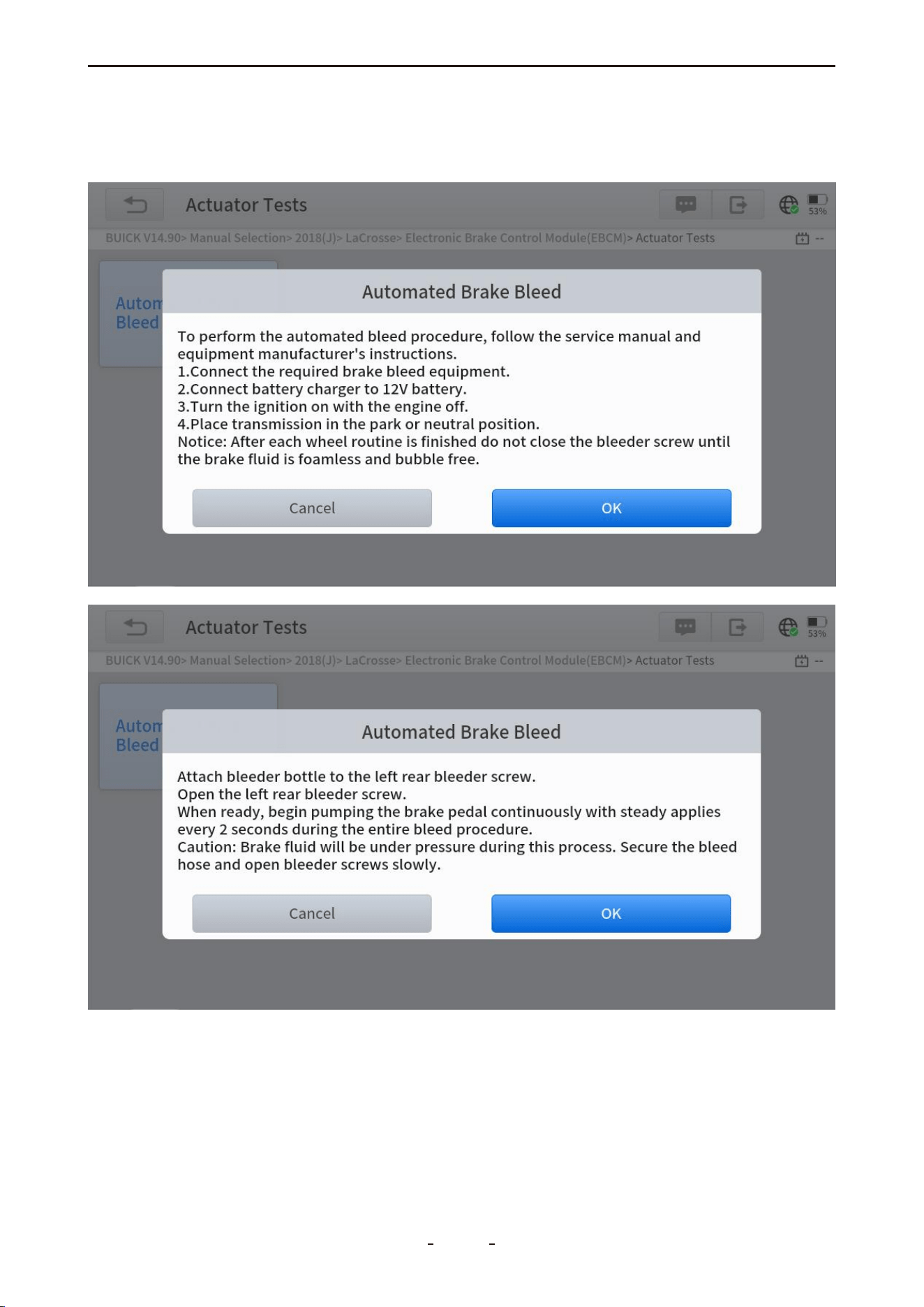
vehicle and equipment are properly prepared.
2. Attach a bleeder bottle to the left rear bleeder screw.
3. Open the left rear bleeder screw.
4. Click "OK" to begin the bleeding procedure. Continuously pump the brake pedal with
steady applications every 2 seconds throughout the process.
67
VD70 Lite Diagnostic Tool
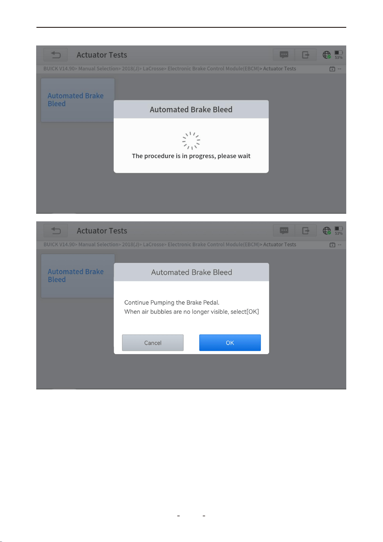
5. Continue pumping until no air bubbles are visible, then select OK to proceed to the left
front wheel.
68
VD70 Lite Diagnostic Tool
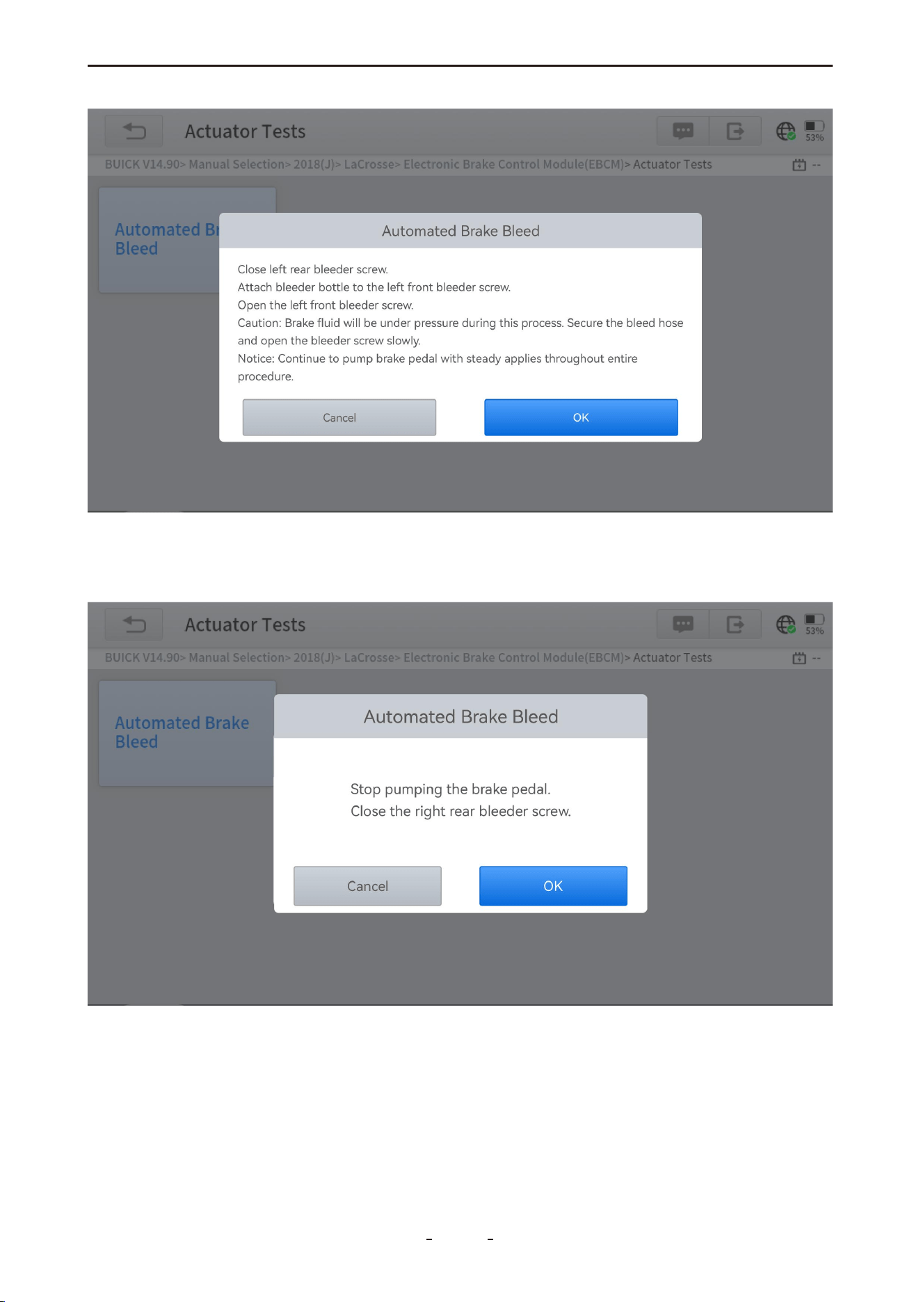
6. Repeat the bleeding operation three times for each wheel in the following sequence: left
front → right front → right rear.
7. Stop pumping the brake pedal and close the right rear bleeder screw.
8. Select OK to complete the procedure.
69
VD70 Lite Diagnostic Tool
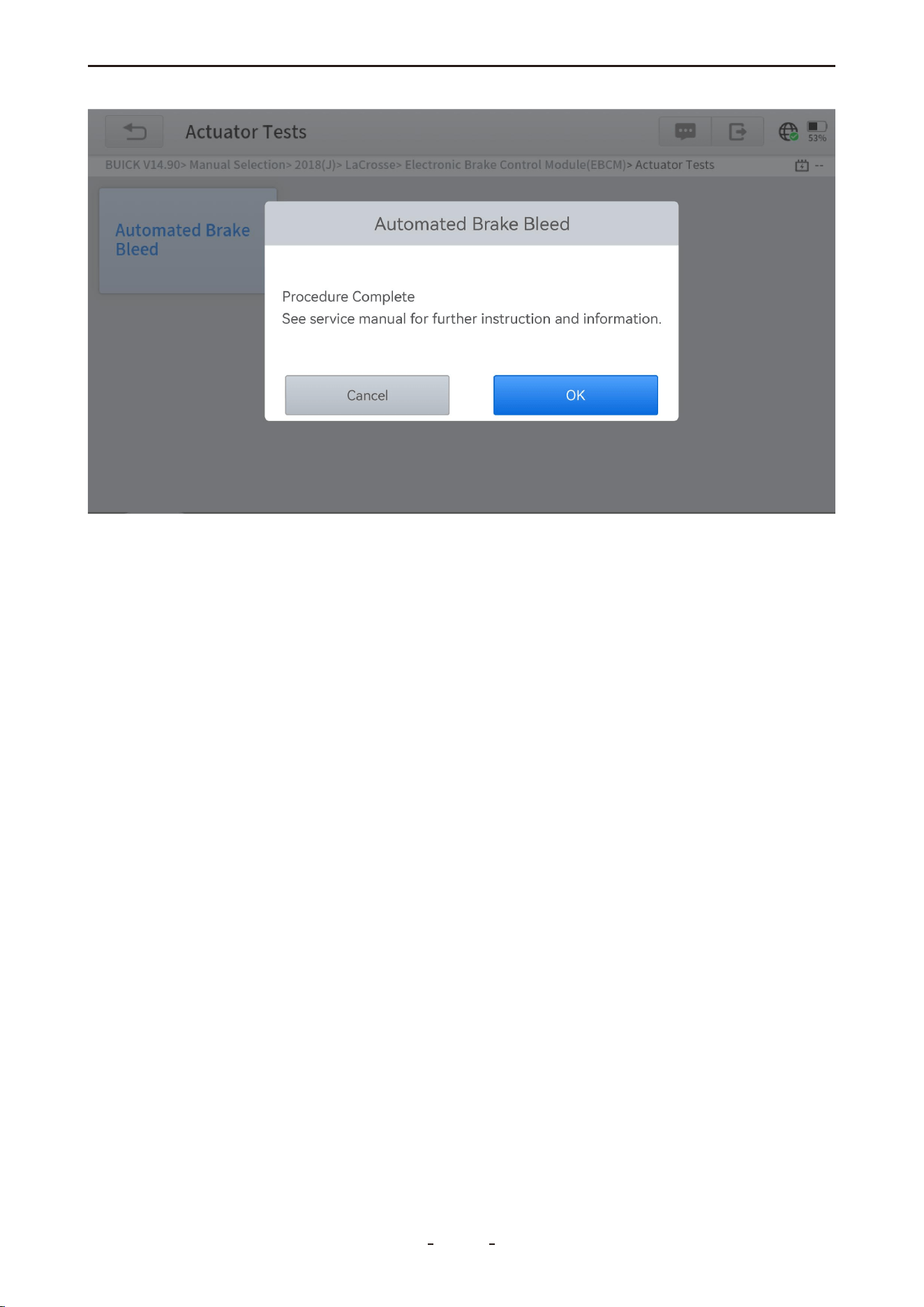
Cautions:
● The ABS pump screw must be loosened before bleeding.
● Brake fluid may be under pressure—secure the bleed hose and open bleeder screws
slowly.
● Some vehicles require manual bleeding instead of automatic support.
6.8 Power Balance
This function sequentially disables individual fuel injectors and monitors the corresponding
drop in engine RPM. By comparing the power output reduction across cylinders, it identifies
underperforming or malfunctioning cylinders based on their relative contribution to engine
power.
6.9 Seat Calibration
Also referred to as Seat Configurations, this function is used to match or configure replaced
or repaired seats equipped with memory functions.
6.10 EEPROM
This function requires the use of an EEPROM adapter (not included in the standard pack-
age) to read from and write data to EEPROM chips.
6.11 Language Change
This function allows you to modify the system language displayed on the instrument cluster
or control console.
6.12 Transport Mode
Vehicles are placed in a partially activated state called Transport Mode during factory ship-
ment to minimize battery drain. This function is used at the dealership to deactivate Trans-
port Mode and fully enable all vehicle systems.
70
VD70 Lite Diagnostic Tool

6.13 Control Unit Reset
This function resets the ECU software to resolve faults caused by abnormal operating tem-
peratures or voltage fluctuations.
6.14 Throttle
Also referred to as Throttle Reset or Throttle Match, this function resets the throttle actua-
tors and clears learned values stored in the ECU, restoring them to default settings. This
ensures precise control of throttle or idle regulation and accurate adjustment of air intake.
6.15 A/F Reset
This function resets or relearns the air/fuel ratio parameters to optimize combustion effi-
ciency.
6.16 HV Battery
This function checks the voltage of individual battery packs in hybrid or electric vehicles.
6.17 Gearbox Match
This function performs transmission self-learning to improve shift quality after disassembly
or repair, resolving issues such as shifting delays or harsh engagement.
6.18 Crank Sensor Relearn
This function performs crankshaft position variation learning to turn off the Malfunction
Indicator Lamp (MIL).
It is required in the following cases:
● After replacing the engine ECU, crankshaft position sensor, or crankshaft flywheel.
● When a DTC indicating "tooth not learned" is present.
6.19 Stop/Start Reset
This function enables or disables the automatic Start/Stop feature by modifying hidden
settings in the ECU (requires vehicle hardware support and hidden function availability).
6.20 EGR Relearn
Also known as EGR Adaptation, this function recalibrates the Exhaust Gas Recirculation
(EGR) valve after cleaning or replacement.
6.21 A/C Relearn
This function performs an AC system recalibration after replacing the AC ECU or actuator,
or when ECU memory loss occurs.
6.22 Headlight
Also referred to as Headlight Adjustment, Headlight Matching, or AFS Reset, this function
initializes the adaptive headlight system. It enables automatic headlight activation based on
ambient light, and adjusts the lighting angle according to vehicle speed, body posture, and
other driving conditions.
71
VD70 Lite Diagnostic Tool

6.23 SRS
This function resets the acceleration sensor when replaced or when providing erroneous
data to systems such as SRS, anti-theft, or navigation.
6.24 Windows Initialization
This function restores the power window automatic operation and ECU memory by per-
forming window matching, typically required after vehicle battery disconnection causes
window malfunction.
6.25 VGT Relearn
Also referred to as VGT Turbo Calibration, this function calibrates newly installed variable
geometry turbocharger (VGT) components. It is required after initial installation or replace-
ment of a VGT, and when the component is detected operating outside its normal range.
6.26 Coolant Bleeding
Also known as Electric Water Pump Activation, this function activates the electric water
pump following its replacement to ensure proper coolant circulation.
6.27 Suspension
This function adjusts the vehicle height sensor and performs level calibration in air suspen-
sion systems. It is used after replacing the height sensor or control module, or when the
vehicle level is incorrect.
6.28 Tire Size Reset
This function resets the tire size configuration in the vehicle system when tires are replaced
or upgraded.
6.29 Sunroof Initialization
When the vehicle battery is disconnected, the windows may not work right. This function is
used to perform sunroof matching to recover the ECU initial memory, and recover the auto-
matic ascending and descending function of power window.
6.30 TCM Oil Reset
The diagnostic tool can be used to reset the TCM oil life system, which calculates the opti-
mum oil life change interval based on the vehicle’s driving conditions and climate. The oil
life reminder must be reset each time the oil is changed so that the system can calculate
when the next oil change is due.
7. Settings
This chapter introduces the configuration options for the diagnostic software and tablet
device, including language selection, measurement units, USB port mode, and other system
preferences.
7.1 Language
To use the diagnostic program in your desired language, please contact our support team
and provide the serial number (S/N) of your diagnostic tool to authorize the corresponding
language software.
72
VD70 Lite Diagnostic Tool
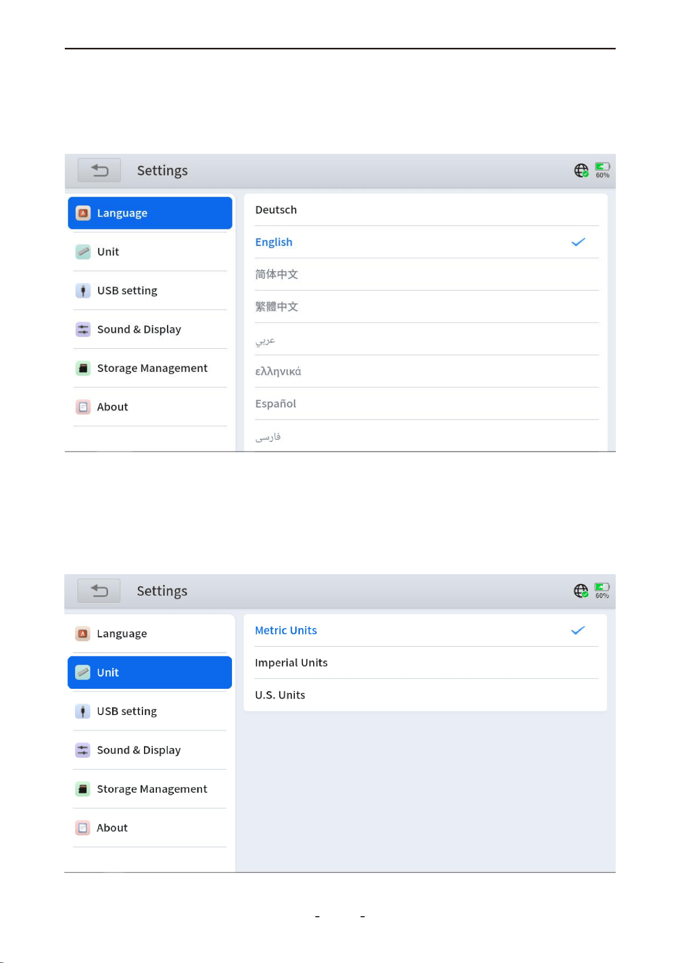
After authorization:
1. Go to Settings → Language on your diagnostic software and select the target language.
2. Navigate to the Update menu to download the complete software package for the newly
set language.
7.2 Unit
This setting offers three unit systems for measuring sensor values:
Metric Units: Centimeters, kilometers, grams, kilograms, °C, liters, Pa, kPa
Imperial Units: Inches, feet, yards, ounces, pounds, °F, PSI, miles, gallons
US Units: Inches, feet, yards, ounces, pounds, °F, PSI, mils, miles
73
VD70 Lite Diagnostic Tool
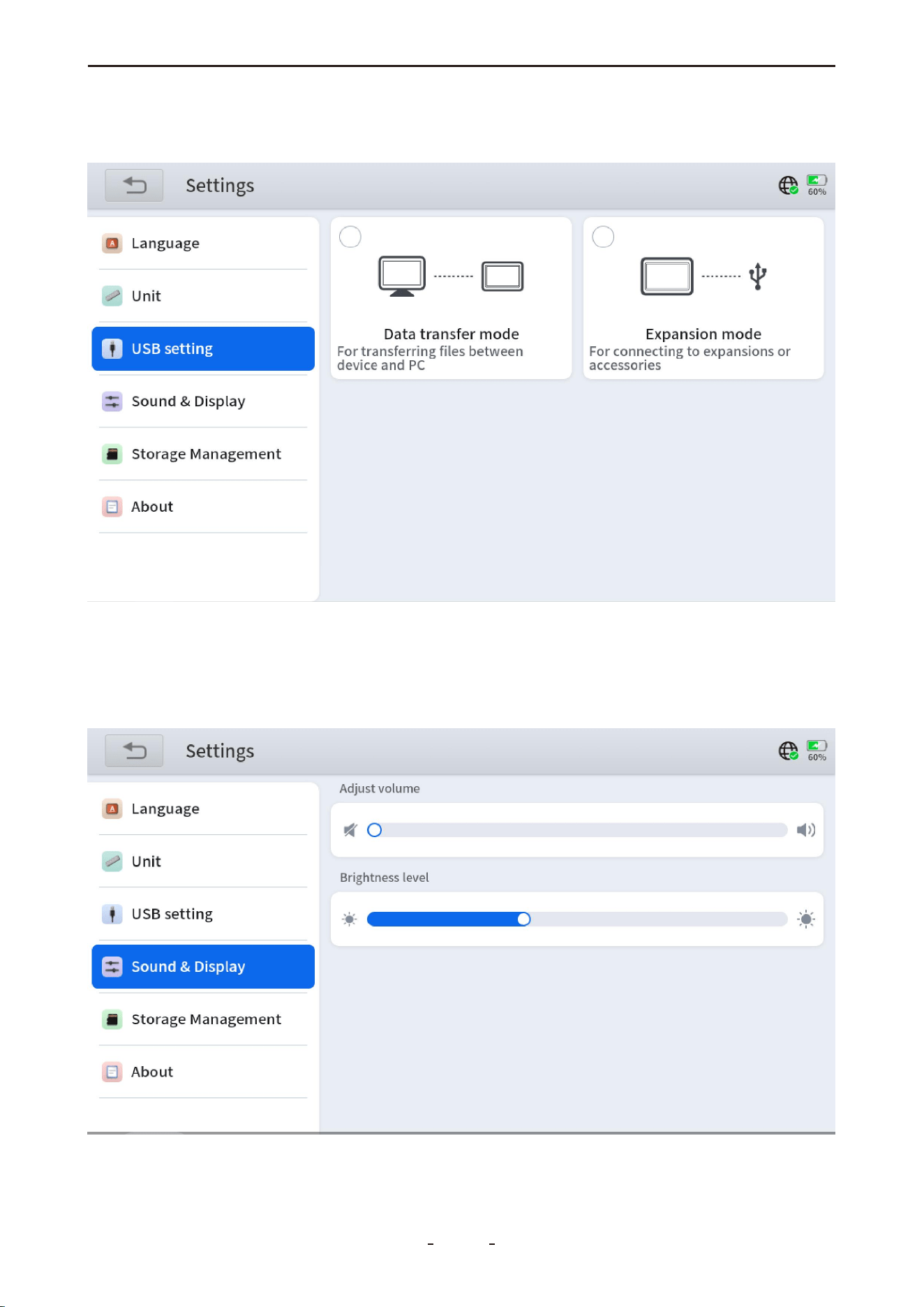
7.3 USB Setting
This option allows you to configure the USB Type-C mode:
7.4 Sound & Display
Adjust the volume of the built-in speaker and the brightness of the display screen.
Data Transfer Mode: Enables data transfer between the Android tablet and a PC.
Expansion Mode: Connect extension accessories (e.g., EEPROM adapter).
74
VD70 Lite Diagnostic Tool
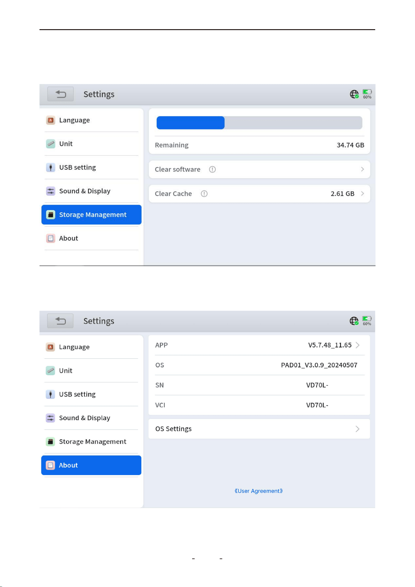
7.6 About
Displays the app version, OS version, diagnostic tool serial number (S/N), and VCI name.
Also allows configuration of operating system settings.
7.5 Storage Management
This function provides access to manage your device's storage space. Here, you can delete
content you no longer need (e.g., diagnostic packages) to free up space.
75
VD70 Lite Diagnostic Tool
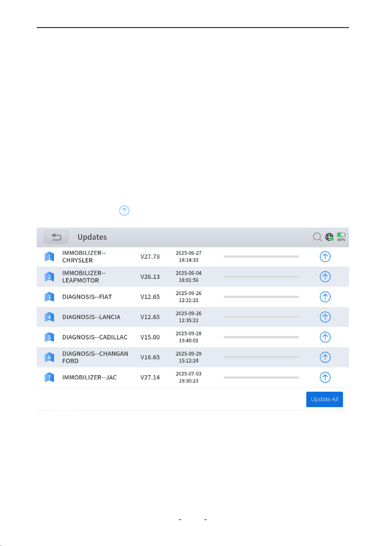
31%
Delete Software Program:
If the diagnostic tool is running slowly due to limited storage space, you can free up
memory by removing rarely used software programs.
To delete a diagnostic software program:
1. Go to Manual Diagnosis → Select Region.
2. Press and hold the icon of the vehicle manufacturer you wish to remove.
3. Tap "Delete" in the menu that appears.
8. Software Updates
This chapter explains the software subscription model and basic update procedures.
This diagnostic tool comes with free lifetime updates and does not require any additional
subscription.
To update, connect the device to Wi‑Fi or a mobile hotspot. A mobile hotspot is recom-
mended for greater reliability and fewer restrictions compared to home Wi‑Fi.
If a “Network abnormal” message appears, try an alternative network, check your router
settings, or contact support at [email protected].
To update the software programs, you have two options:
Option 1: Update All Software Programs
Tap "Update All" at the bottom right of the update screen to update all programs at once.
Option 2: Update Individual Software Program
Tap the "Update" icon next to any program to update it individually. If the update is
interrupted, tap the icon again to resume.
76
VD70 Lite Diagnostic Tool

9. More
This chapter introduces the “More” options available in the main diagnostic menu, covering
user account settings, workshop information, subscription start and end dates, firmware
details, endoscope-related functions, and the user manual.
9.1 Profile
This section enables you to manage user account settings, configure workshop details, and
review subscription information.
● Account Information - Set your username, register your product via email, reset your
password, or log out of the current account to switch to a different one.
● Workshop - Technicians or workshops can enter their workshop name, address, phone
number, email, and website. These details will be included in diagnostic reports shared with
customers.
● Subscription - View the diagnostic tool’s serial number (S/N), activation start date.
9.2 User Manual
To better serve our customers, we frequently update and improve the user manual.
Physical copies of the manual can become outdated quickly. In contrast, the digital PDF
version allows you to easily search for specific information within its comprehensive con-
tent. Therefore, we have included this section to provide timely access to the latest version
of the user manual.
Note:
The user manual on our website is updated more frequently than the diagnostic tool app.
For the most current version, please visit: www.vdiagtool.com.
9.3 Vehicle Coverage
This functions allow you check the compatibility between your vehicle and the diagnostic
tool. However, this is for reference only. For better compatibility confirm, please provide
your device S/N, your vehicle VIN and the desired functions to our tech support team at
10. Other Settings
10.1 Email Settings
To configure your Gmail account for sending diagnostic reports, follow these steps:
Step 1: Log in to your Google Account and enable 2-Step Verification by going to Security
→ 2-Step Verification → Get Started, then adding a backup phone to complete the setup.
77
VD70 Lite Diagnostic Tool
Step 2: Once enabled, visit https://myaccount.google.com/apppasswords to generate an
App Password.
Step 3: Enter a custom name (e.g., "VD70 Lite"), click "Generate", then immediately copy and
save the 16-character password.
78
VD70 Lite Diagnostic Tool
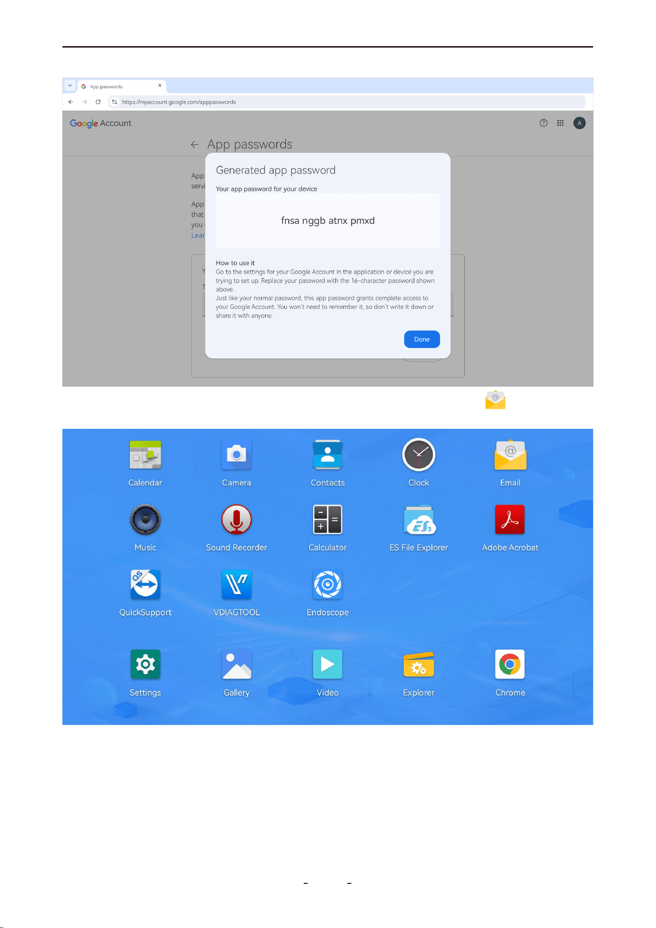
Step 4: On your diagnostic tool, swipe up to reveal the toolbar, tap the " " icon to add a
new email account.
Step 5: Enter your full Gmail address and paste the 16-character App Password (not your
regular password), then tap "Next".
79
VD70 Lite Diagnostic Tool
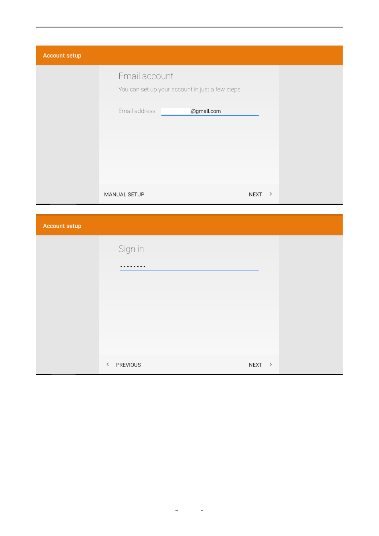
Note:
If the configuration does not proceed automatically and a prompt appears, manually tap
“EDIT DETAILS” to enter the following mail server settings:
80
VD70 Lite Diagnostic Tool
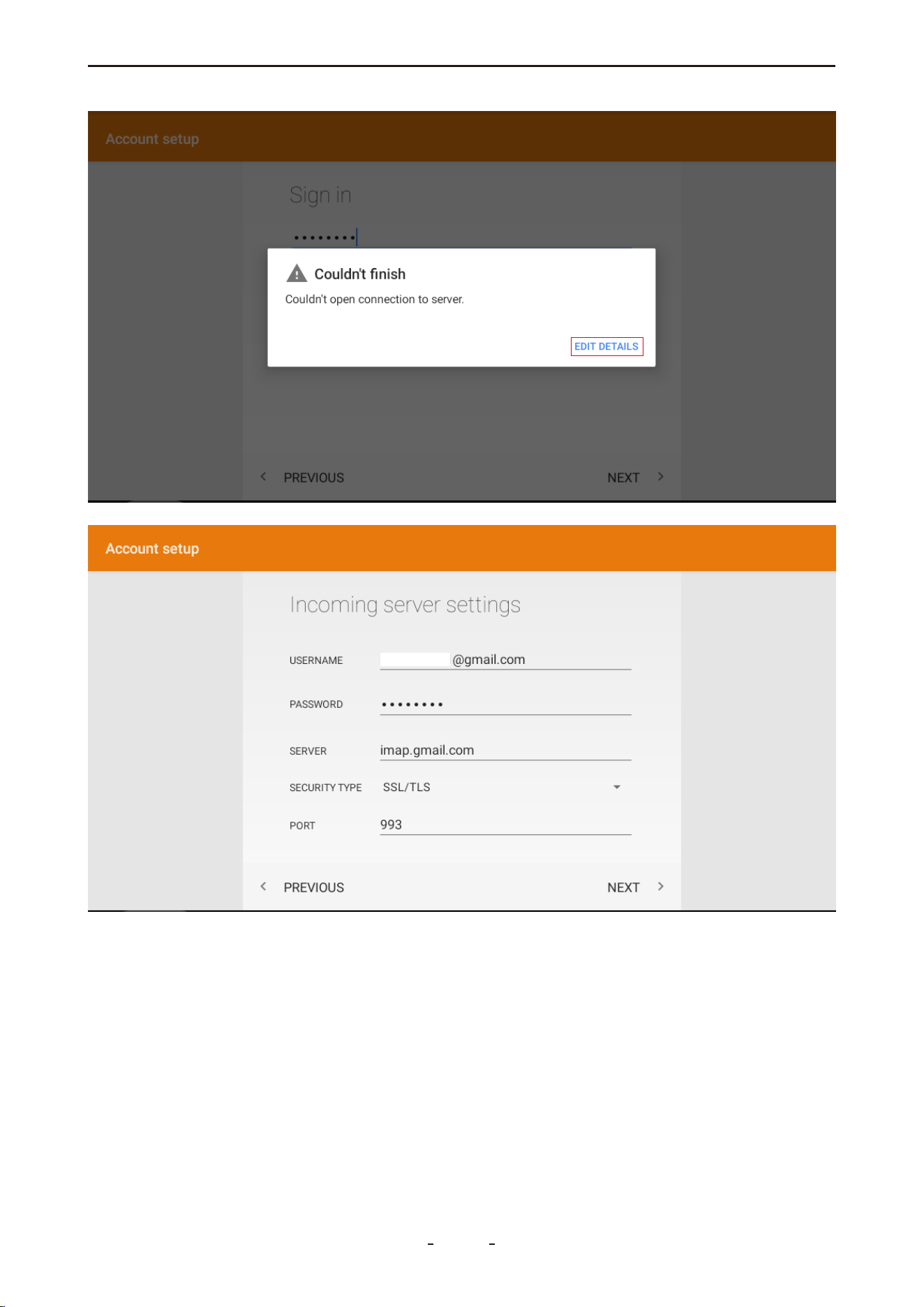
Mail Server Settings (Gmail):
Server Type Server Address Port Security Type
Incoming (IMAP) imap.gmail.com 993 SSL/TLS (or SSL)
Incoming (POP3) pop.gmail.com 995 SSL/TLS (or SSL)
Outgoing (SMTP) smtp.gmail.com 465 (SSL) SSL/TLS
587 (TLS) STARTTLS
81
VD70 Lite Diagnostic Tool
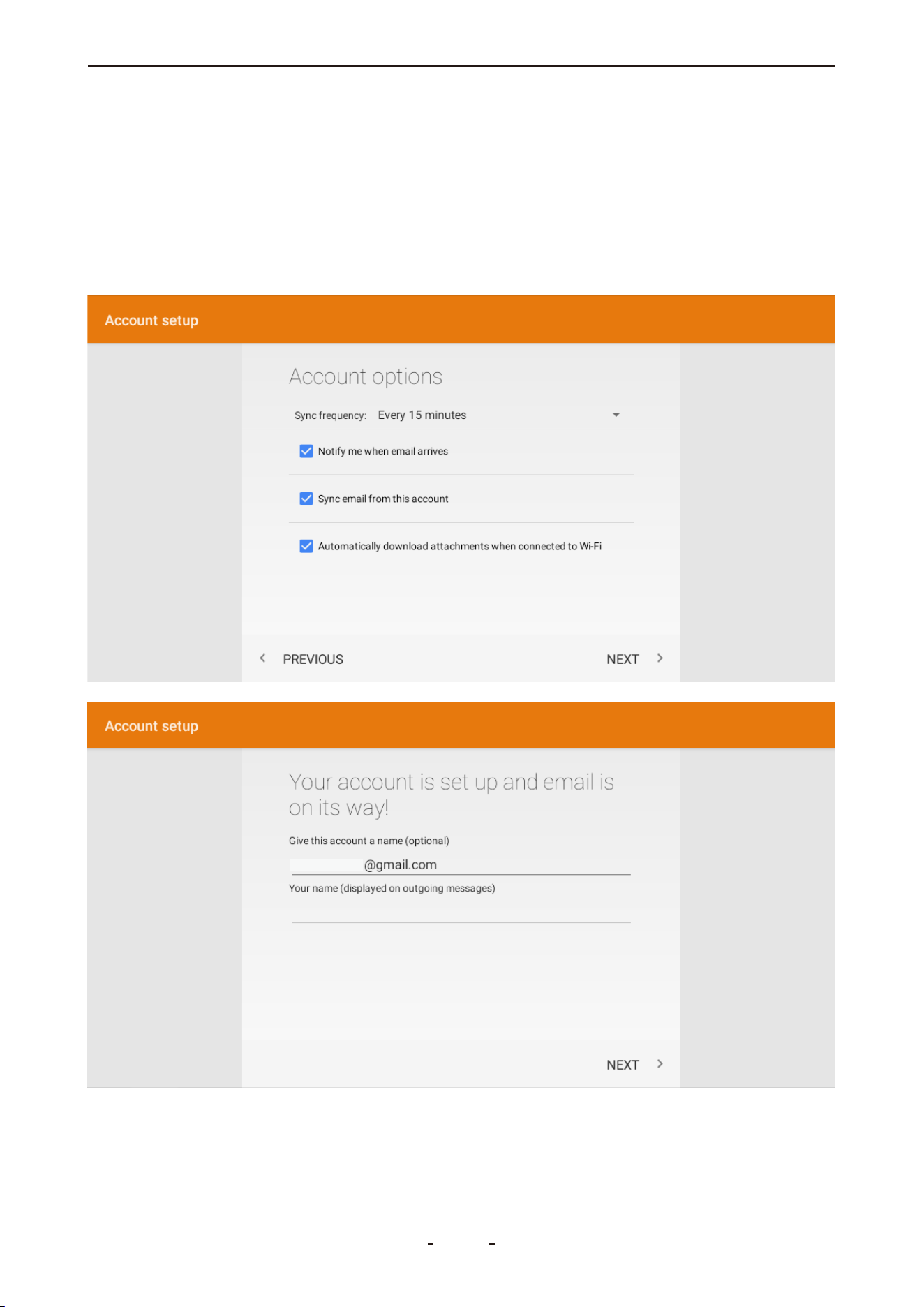
These settings are specific to Gmail. If you continue to experience issues, please ensure you
are using an App Password instead of your regular Gmail password if 2-Step Verification is
enabled.
For further assistance or updated configuration guidelines, we recommend searching
online for "Gmail server settings" or visiting official Gmail help resources.
Step 6: Set your sync frequency and complete the setup until you see the confirmation:
"Your account is set up and emails are on their way."
82
VD70 Lite Diagnostic Tool
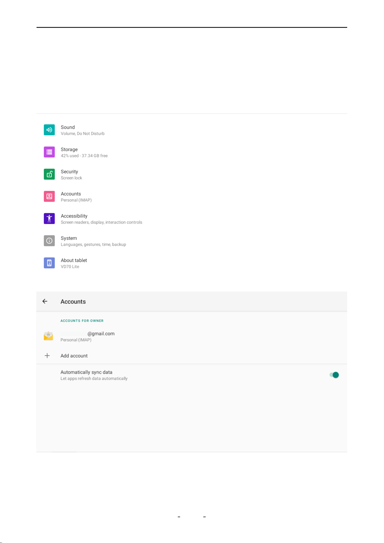
To Share a Diagnostic Report via Gmail:
Go to Report, select the target report, and tap “Print PDF Report”. Then, tap the menu icon
in the top right corner, choose “Share” → “Email”, and send the report using your Gmail
account.
10.2 Delete Email Account
Step 1: Swipe up to open the hidden toolbar menu and tap “Accounts”.
Step 2: Select the Gmail account you wish to remove.
83
VD70 Lite Diagnostic Tool
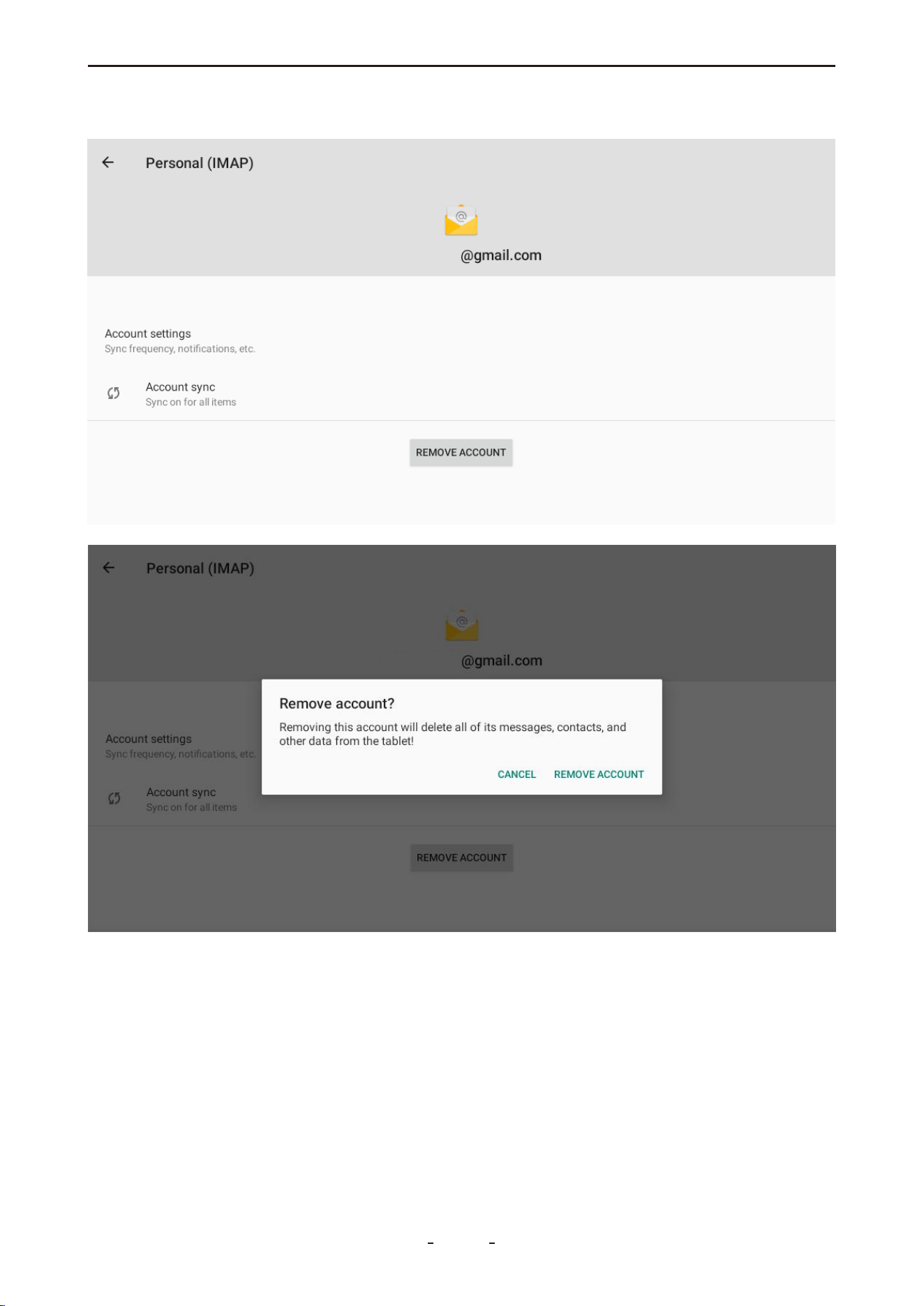
Step 3: Tap “REMOVE ACCOUNT” and confirm the operation when prompted.
84
VD70 Lite Diagnostic Tool

10.3 Printing Settings
To enable the printing service on your diagnostic tool, you must first install a compatible
print service app or driver. Please review the following checklist before proceeding with the
installation.
10.3.1 Checklist for Installing Printing Service:
● Ensure your printer supports Wi-Fi or Wi-Fi Direct connection.
● Confirm the brand and model of your printer.
● Install a print service app (printer driver) compatible with your printer. You have two
options:
Option 1: Install a universal printer service app (e.g., Mopria).
Option 2: Install the official app provided by your printer manufacturer (e.g., HP Printing
Service for HP printers).
10.3.2 Install Mopria Print Service or Specialized Driver
To install the printing service via APK file, follow these steps:
Step 1: On a computer, visit the Mopria official website at https://mopria.org/ (or your print-
er manufacturer’s website).
Step 2: Navigate to Print → Print From Android → Direct Download to obtain the APK file.
85
VD70 Lite Diagnostic Tool
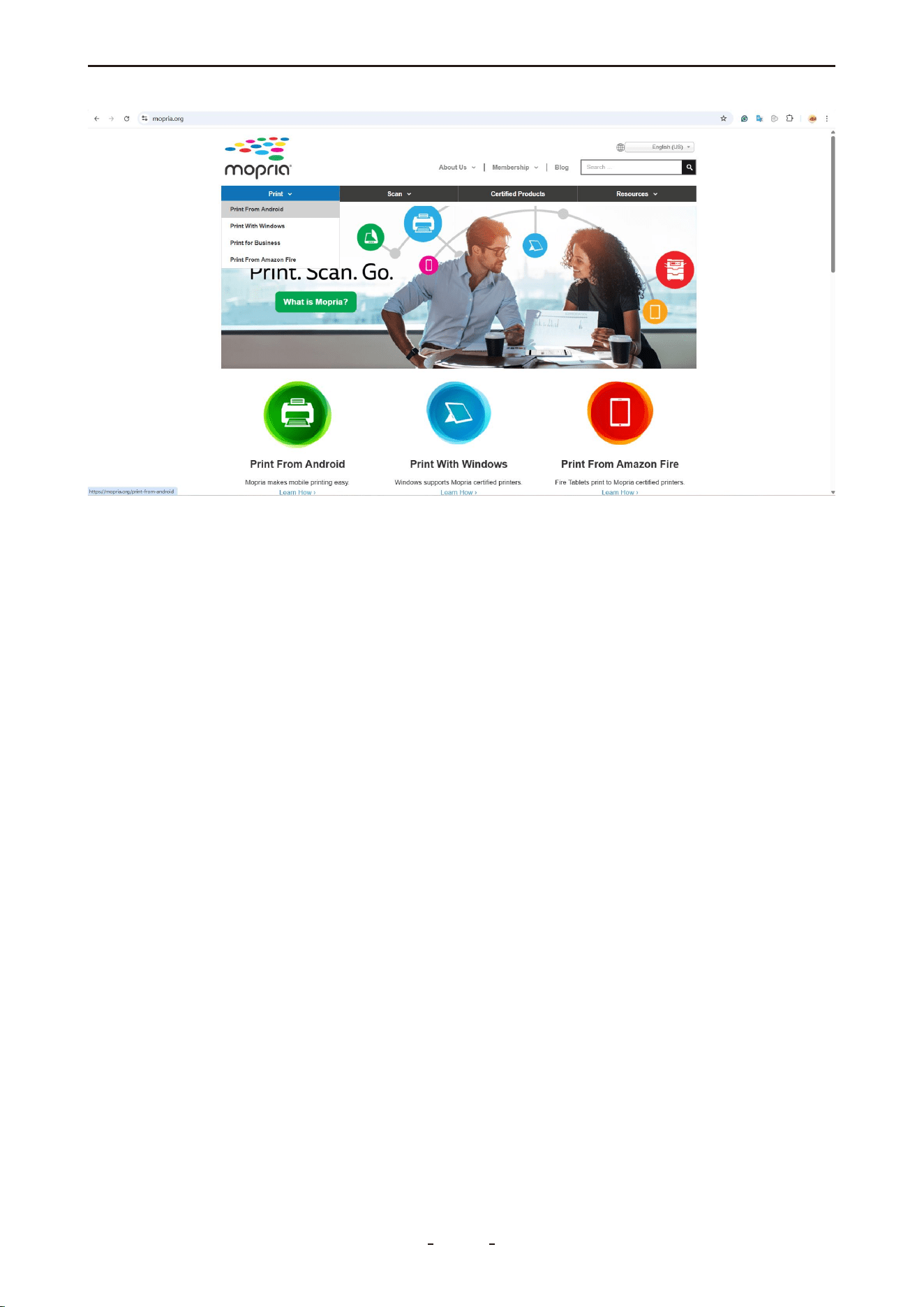
Step 3: Connect the diagnostic tool to the computer using the provided USB Type-C cable.
On the tool, swipe down from the top edge to open the notification panel, select File Trans-
fer.
Step 4: Transfer the downloaded APK file to the following folder on the diagnostic tool:
VD70 Lite → Internal Shared Storage → Download
Step 5: Disconnect the USB connection. Open ES File Explorer on the tool, go to: Explorer →
Local → Home → Download, locate the APK file and tap it to begin installation.
86
VD70 Lite Diagnostic Tool

Step 6: After installation, go to: Settings → Connected Devices → Connection Preferences →
Printing, tap Mopria Print Service, turn the switch ON, select your printer, and accept any
connection prompt on the printer’s control panel.
87
VD70 Lite Diagnostic Tool
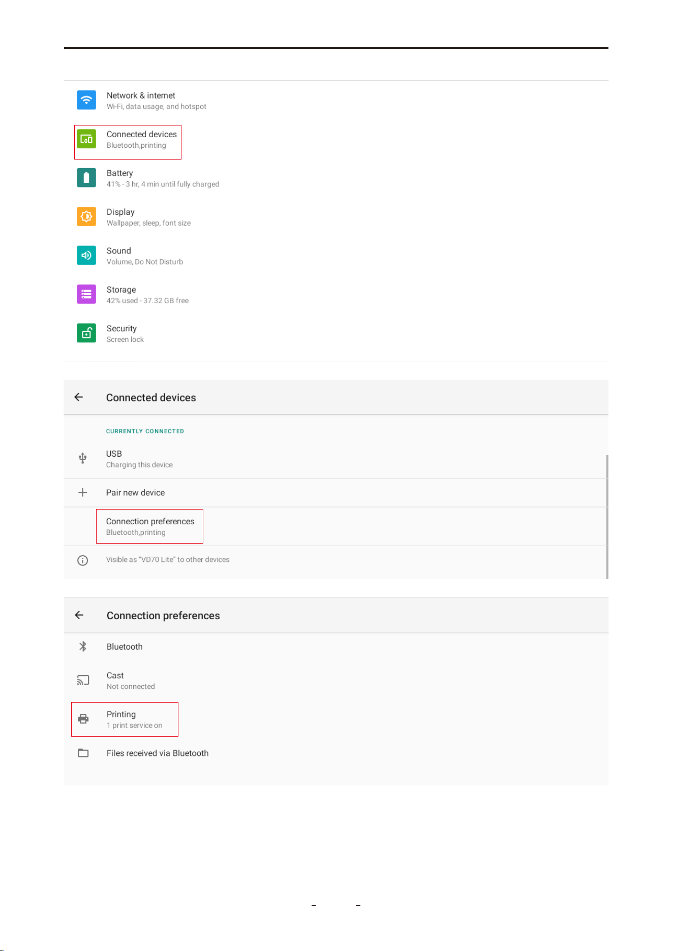
88
VD70 Lite Diagnostic Tool
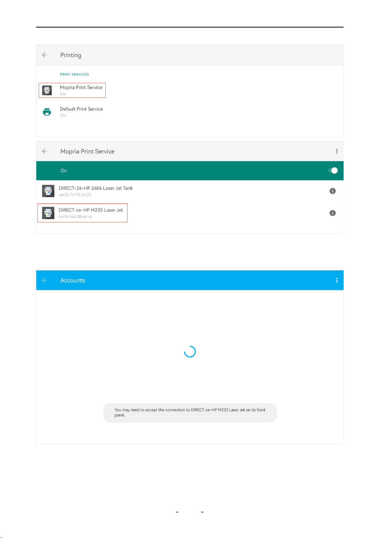
Important:
For some printers, you must manually approve the connection request directly on the print-
er's control panel.
89
VD70 Lite Diagnostic Tool
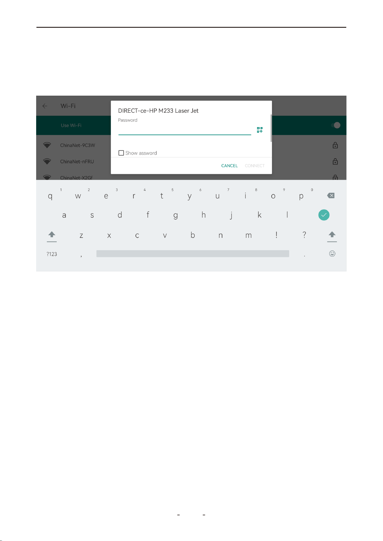
10.4 For Printer with Wi-Fi Direct
If your printer supports Wi-Fi Direct, follow the steps below to connect the diagnostic tool
directly to the printer:
Step 1: Swipe up to open the hidden toolbar menu and tap “Settings”.
Step 2: Go to Network & internet → Wi-Fi, then select your printer’s Wi-Fi network.
Step 3: Find the SSID and password on your printer’s front display or control panel. If your
printer does not have a display, print a network configuration page from the printer to
obtain these details.
11. Service Center
This section provides various ways you can contact us, including warranty claims, technical
support, video tutorials, marketing collaboration, business opportunities, and feedback to
help us improve diagnostic tools.
90
VD70 Lite Diagnostic Tool

11.1 Remote Control
This function allows you to request remote assistance from our technical team. They can
directly operate the diagnostic tool to help you with unfamiliar functions or procedures.
To use remote assistance:
1. Ensure your diagnostic tool is connected to a Wi-Fi network.
2. Tap the “Remote Control” icon to launch TeamViewer.
3. Wait until the status “Ready to connect (secure connection)” appears at the bottom left
of the screen.
4. Provide the TeamViewer ID (displayed in the center-right of the screen) to our support
team when scheduling a remote session in advance.
91
VD70 Lite Diagnostic Tool
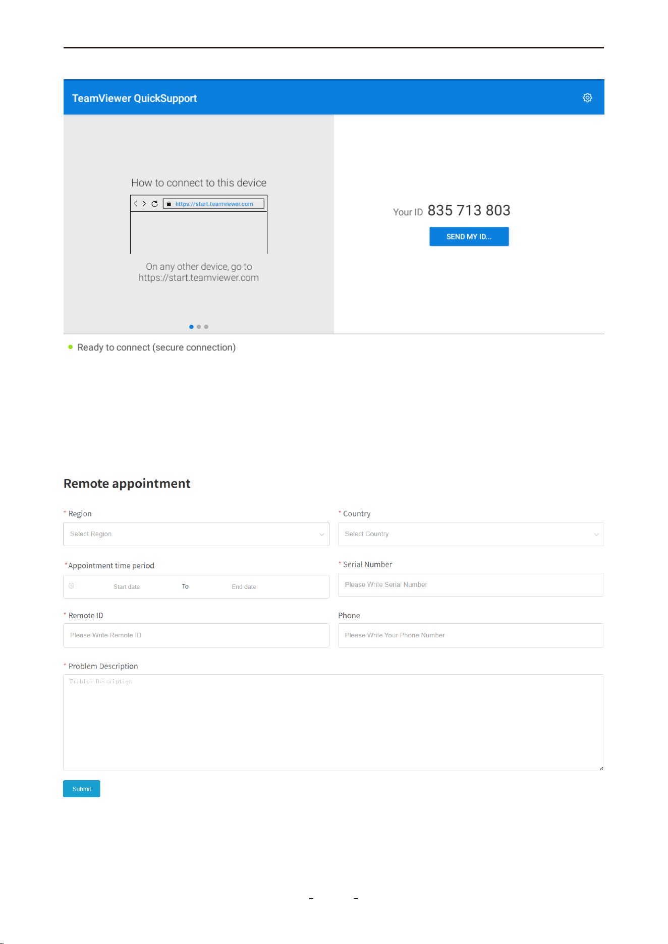
11.2 Schedule a Remote Control
To schedule a remote assistance session with our technical team, please follow these steps:
1. Visit our official website: www.vdiagtool.com
2. Navigate to “Support” → “Tech Support”, or directly access:
https://www.vdiagtool.com/support/tech-support
3. Complete the “Remote Assistance” form with your request and details.
92
VD70 Lite Diagnostic Tool

Form Field Description:
Region - Your current region.
Country - Your country of residence.
Appointment Time Period - Your preferred time slot for the remote assistance.
Serial Number - The serial number (S/N) of your diagnostic tool.
Remote ID - The TeamViewer ID displayed on your device.
Phone - Your phone number so our technician can contact you during the remote assis-
tance if needed.
Problem Description - Briefly describe the issue you are experiencing with the diagnostic
tool or vehicle. Providing clear details helps our technician prepare in advance.
11.3 Data Logging
For software-related issues—such as vehicle communication failures or function
errors—data logs are often essential for effective troubleshooting. To ensure our technical
team can retrieve and analyze these logs, please keep your diagnostic tool connected to
Wi-Fi for at least 15 minutes and provide its serial number (S/N) when submitting a support
request.
12. Compliance Information
12.1 Regulatory Compliance Statements
United States (FCC)
FCC ID: 2BE93VDT700
This device complies with Part 15 of the FCC Rules. Operation is subject to the following two
conditions: (1) this device may not cause harmful interference, and (2) this device must
accept any interference received, including interference that may cause undesired opera-
tion.
Note: This equipment has been tested and found to comply with the limits for a Class B
digital device, pursuant to part 15 of the FCC Rules. These limits are designed to provide
reasonable protection against harmful interference in a residential installation. This equip-
ment generates, uses and can radiate radio frequency energy and, if not installed and used
in accordance with the instructions, may cause harmful interference to radio communica-
tions.
Interference Guidance: If this equipment does cause harmful interference to radio or televi-
sion reception, which can be determined by turning the equipment off and on, the user is
encouraged to try to correct the interference by one or more of the following measures:
● Reorient or relocate the receiving antenna.
● Increase the separation between the equipment and receiver.
● Connect the equipment into an outlet on a circuit different from that to which the receiver
is connected.
● Consult the dealer or an experienced radio/TV technician for help.
Warning: Changes or modifications not expressly approved by the party responsible for
compliance could void the user's authority to operate the equipment.
93
VD70 Lite Diagnostic Tool

Canada (ISED)
IC: 32118-VDT700
This device contains licence-exempt transmitter(s)/receiver(s) that comply with Innovation,
Science and Economic Development Canada's licence-exempt RSS(s). Operation is subject
to the following two conditions:
(1) This device may not cause interference.
(2) This device must accept any interference, including interference that may cause unde-
sired operation of the device.
Français:
Cet appareil contient des émetteurs/récepteurs exempts de licence qui sont conformes aux
RSS exempts de licence d'Innovation, Sciences et Développement économique Canada.
Son fonctionnement est soumis aux deux conditions suivantes :
(1) Le présent appareil ne doit pas produire de brouillage.
(2) Le présent appareil doit accepter tout brouillage radioélectrique subi, même si le brouil-
lage est susceptible d’en compromettre le fonctionnement.
12.2 RF Exposure & SAR (FCC & ISED)
This device complies with FCC and ISED Canada RF exposure guidelines. Its radiated output
power is below the radio frequency exposure limits.
The Specific Absorption Rate (SAR) is measured using standard operating positions with the
device transmitting at its highest certified power level. The FCC SAR limit is 1.6 W/kg. The
device is designed to operate at multiple power levels to minimize exposure and uses only
the necessary power to maintain communication.
To ensure compliance with RF exposure requirements, minimize human contact with the
antenna during normal operation.
12.3 Additional Compliance (RoHS, CE & UKCA)
RoHS: This product is compliant with Directive 2011/65/EU on the restriction of hazardous
substances.
CE: This product conforms to the essential requirements of the following European Direc-
tives:
EMC Directive 2014/30/EU
RED Directive 2014/53/EU
Low Voltage Directive 2014/35/EU
UKCA: This product is declared to conform to the essential requirements of the relevant UK
statutory instruments and carries the UKCA mark accordingly.
13. Warranty
Limited Two-Year Warranty
This warranty is expressly granted to buyers who purchase the VDIAGTOOL VD70 Lite prod-
uct for resale or for use in the ordinary course of their business.
VDIAGTOOL warrants that the VD70 Lite diagnostic tool shall be free from defects in materi-
als and workmanship for a period of two years (24 months) from the date of delivery to
the original buyer.
94
VD70 Lite Diagnostic Tool

This warranty does not cover any part that has been subjected to misuse, alteration, used
for unintended purposes, or operated in a manner inconsistent with the product instruc-
tions. The exclusive remedy for any tool found to be defective under this warranty shall be,
at VDIAGTOOL’s option, repair or replacement of the product. VDIAGTOOL shall not be
liable for any consequential or incidental damages arising from the use or inability to use
the product.
14. Contact Us
Warranty & Support
Email: [email protected]
Website: www.vdiagtool.com
For wholesale business or become our distributors:
Email: [email protected]
Invent with us, test products before they hit market, help us make better products for
everyone:
Email: [email protected]
Create social media content, post online and help our community:
Email: [email protected]
Follow Us on Social Media
Facebook Page: Search for "vdiagtool"
Facebook User Group: Search for "VDIAGTOOL OFFICIAL User Group"
Instagram: Search for "vdiagtool_official"
TikTok: Search for "vdiagtool_us"
YouTube: Search for "Vdiagtool Official"
95
VD70 Lite Diagnostic Tool

15. Appendix
15.1 Navigation Path Quick Reference
● Misfire Counters: MANUAL DIAGNOSIS → Region → OBDII → Auto Scan/Protocol Selec-
tion → On-Board Monitoring Test → Misfire Counters
● Fuel Loop Status: MANUAL DIAGNOSIS → OBDII → Live Data → Fuel System 1 / Fuel
System 2
● Readiness Status (Smog Check): MANUAL DIAGNOSIS → OBDII → I/M Readiness Status
● Transmission Oil Temperature: MANUAL DIAGNOSIS → Region → Make → Model →
Year → Transmission or Powertrain → Live Data → Transmission Oil Temperature / Transmis-
sion Fluid Temperature
● Cam Crank Relearn: MANUAL DIAGNOSIS → Region → Vehicle Selection → System
Selection → Engine or ECT or Powertrain → Special Function → Cam Crank Relearn / Crank
Pattern Learning
● Crankshaft Position Variation Sensor Relearn: MANUAL DIAGNOSIS → Region → Vehi-
cle Selection → System Selection → Engine Control Module / Powertrain → Special Function
→ Crankshaft Position Variation Learn
● Service Bay Test: MANUAL DIAGNOSIS → Region → Vehicle Selection → System Selec-
tion → Engine Control Module / Powertrain → Actuation Test or Special Function → EVAP
Service Bay Test
● VGT Turbo Calibration: MANUAL DIAGNOSIS → Region → Vehicle Selection → System
Selection → Drive Train Control Module → Special Function → Turbo Actuator Pre-Align /
Self Calibrate
15.2 Terms & Terminology Quick Reference
● LTFT: Long Term Fuel Trim
● STFT: Short Term Fuel Trim
● MIS: Misfire
● I/M Readiness Status: Smog Check
● VGT Turbo Actuator Calibration: Also known as Turbo Actuator Pre-Align or Self Cali-
brate
● Cam Crank Relearn: Also referred to as Cam Pattern Relearn
● Crankshaft Position Variation Learn: May be displayed as Crankshaft Relearn, CASE
Learning, or Gear Learning
● Actuation Test: Also called Active Test, Component Test, or Bi-Directional Control
15.3 FAQs
Q1: Why can't I find the I/M Readiness function in the menu?
A: To access I/M Readiness, enter Manual Diagnosis, select the region (e.g., America/Eu-
rope/Asia), tap the "OBDII" icon in the upper-left corner, perform an Auto Scan or manually
select the OBDII Protocol, and then choose I/M Readiness from the menu.
Q2: Why can't I find live sensor data such as Short-Term/Long-Term Fuel Trim like a generic
OBD2 scanner?
A: To access live OBD2 data (including LTFT and STFT), please enter Diagnosis, select the
appropriate region (e.g., America / Europe / Asia), tap the "OBDII" icon in the upper-left
corner, perform an Auto Scan or manually choose the OBDII Protocol, enter Live Data, and
then select the desired parameters such as LTFT, STFT, or related terms.
96
VD70 Lite Diagnostic Tool

15. Appendix
15.1 Navigation Path Quick Reference
● Misfire Counters: MANUAL DIAGNOSIS → Region → OBDII → Auto Scan/Protocol Selec-
tion → On-Board Monitoring Test → Misfire Counters
● Fuel Loop Status: MANUAL DIAGNOSIS → OBDII → Live Data → Fuel System 1 / Fuel
System 2
● Readiness Status (Smog Check): MANUAL DIAGNOSIS → OBDII → I/M Readiness Status
● Transmission Oil Temperature: MANUAL DIAGNOSIS → Region → Make → Model →
Year → Transmission or Powertrain → Live Data → Transmission Oil Temperature / Transmis-
sion Fluid Temperature
● Cam Crank Relearn: MANUAL DIAGNOSIS → Region → Vehicle Selection → System
Selection → Engine or ECT or Powertrain → Special Function → Cam Crank Relearn / Crank
Pattern Learning
● Crankshaft Position Variation Sensor Relearn: MANUAL DIAGNOSIS → Region → Vehi-
cle Selection → System Selection → Engine Control Module / Powertrain → Special Function
→ Crankshaft Position Variation Learn
● Service Bay Test: MANUAL DIAGNOSIS → Region → Vehicle Selection → System Selec-
tion → Engine Control Module / Powertrain → Actuation Test or Special Function → EVAP
Service Bay Test
● VGT Turbo Calibration: MANUAL DIAGNOSIS → Region → Vehicle Selection → System
Selection → Drive Train Control Module → Special Function → Turbo Actuator Pre-Align /
Self Calibrate
15.2 Terms & Terminology Quick Reference
● LTFT: Long Term Fuel Trim
● STFT: Short Term Fuel Trim
● MIS: Misfire
● I/M Readiness Status: Smog Check
● VGT Turbo Actuator Calibration: Also known as Turbo Actuator Pre-Align or Self Cali-
brate
● Cam Crank Relearn: Also referred to as Cam Pattern Relearn
● Crankshaft Position Variation Learn: May be displayed as Crankshaft Relearn, CASE
Learning, or Gear Learning
● Actuation Test: Also called Active Test, Component Test, or Bi-Directional Control
15.3 FAQs
Q1: Why can't I find the I/M Readiness function in the menu?
A: To access I/M Readiness, enter Manual Diagnosis, select the region (e.g., America/Eu-
rope/Asia), tap the "OBDII" icon in the upper-left corner, perform an Auto Scan or manually
select the OBDII Protocol, and then choose I/M Readiness from the menu.
Q2: Why can't I find live sensor data such as Short-Term/Long-Term Fuel Trim like a generic
OBD2 scanner?
A: To access live OBD2 data (including LTFT and STFT), please enter Diagnosis, select the
appropriate region (e.g., America / Europe / Asia), tap the "OBDII" icon in the upper-left
corner, perform an Auto Scan or manually choose the OBDII Protocol, enter Live Data, and
then select the desired parameters such as LTFT, STFT, or related terms.
97
VD70 Lite Diagnostic Tool

Q3: Why can't I find misfire data for my Ford/Dodge/Chrysler/Jeep vehicle?
A: To access misfire data, please navigate as follows: Manual Diagnosis → select region (e.g.,
America/Europe/Asia) → tap the OBDII icon (located in the upper-left corner) → perform an
Auto Scan or manually select the OBDII Protocol for your vehicle → enter On-Board Monitor
Test → then choose "Misfire Cylinder Data" or a similar menu option.
Q4: How can I export live data as a CSV file?
A: To generate a CSV file: While viewing Live Data, tap the Menu or Export icon, select
Custom or set desired parameters, then choose Export to CSV or a similar option.
To locate the exported file: Open ES File Explorer, navigate to Internal Storage → diagnosis
→ csv_records, and your CSV files will be stored there.
Q5: The device is not charging when plugged in. The battery is very low (around 10%). What
should I do?
A: Please charge the device for at least one hour, then unplug the USB-C cable, press and
hold the power button for 15 seconds, release it, and check if the device powers on success-
fully.
Q6: When activating the device, shows error message "registration failure" after entering
your email address.
A: This issue is often network-related; please try using a mobile hotspot (recommended) or
switching to a different Wi-Fi network, then attempt activation again.
Q7: When entering the diagnosis software, error messages such as "license exception" or
"Failed" are displayed. How can this be resolved?
A: Please try pressing and holding the diagnosis software icon to uninstall it, then re-down-
load the software from the "Updates" section. If the issue continues, contact our support
team at [email protected] with your diagnostic tool's serial number (S/N) for further
assistance.
Q8: I cannot update. I've tried both Wi-Fi and mobile hotspot, but it keeps showing connec-
tion failure. What should I do?
A: This issue is commonly caused by network restrictions, such as router firewall settings or
regional network limitations. Please check whether your network allows access to the
update server. If the problem continues, contact our support team at support@vdiag-
tool.com for assistance.
Q9: Is it possible to install the Google Play Store on the diagnostic tool?
A: This device does not support the Google Play Store. If you wish to install a third-party
application, you may manually install it via an APK file. Please note, however, that we do not
recommend installing third-party apps as they may impact device performance and stabili-
ty.
98
VD70 Lite Diagnostic Tool

Q10: Why can't the automatic VIN feature recognize my vehicle?
A: Automatic VIN scanning may not work on all vehicles. This can occur if the VIN is not
stored in the ECU, is not yet included in our database, or if the vehicle (such as some Dodge
models) uses a command-based communication protocol. You can try the following alter-
natives:
● Turn the ignition ON but do not start the engine, then attempt an auto scan. For older
vehicles, try with the engine running.
● Manually enter the VIN.
● Navigate to: Diagnosis → Select Region → Vehicle Selection → Automatic Detection.
● Navigate to: Diagnosis → Select Region → Vehicle Selection → Manual Selection.
Q11: Why can't my diagnostic tool connect to Wi-Fi?
A: Connection issues can arise from several causes. Please try the following solutions based
on your situation:
● If the connection times out, check your router settings. Ensure it is set to WPA2 (not
WPA3) for maximum compatibility, and confirm it does not block traffic to regions like
China. Using a mobile hotspot often resolves this; you can switch back to your home Wi-Fi
after activation.
● If you use a Wi-Fi extender, try disconnecting from the main router and connecting direct-
ly to the extender.
● If the tool is connected to the internet but displays “connect internet to sync your device,”
the issue may be a time zone mismatch. Please set the time zone to Pacific Time by going
to: Main Screen → Settings → System → Date & Time → Select Time Zone.
Q12: How can I change the menu language to Spanish?
A: To use the diagnostic tool in Spanish, please contact [email protected] with your
device's serial number (S/N) to request authorization for the Spanish software. Once autho-
rized, go to Settings → Language and select Spanish, then navigate to Updates to download
and install all available Spanish software packages. After installation is complete, the inter-
face will be fully available in Spanish.
Q13: Why does the scanner show "report shared successfully," but I don't receive the email?
A: Reports are sent from our email address: [email protected]. Even if the
device shows "send successfully," your email provider may block this message. Since you
use Gmail, you can try whitelisting our sender address to prevent blocking. Instructions can
be found here:
https://downtimemonkey.com/blog/how-to-whitelist-an-email-address-in-gmail.php
Note that not every user needs to set up a whitelist, as blocking does not always occur. You
may also check your spam or junk folder for messages from noreply@service-vdiag-
tool.com.
99
VD70 Lite Diagnostic Tool