VD80 BT WIRELESS DIAGNOSTIC TOOL
USER MANUAL
Legal Information
Trademarks
VDIAGTOOL is a trademark, registered in the United States and other countries, of Shen-
zhen VDIAGTOOL Technology Co., Ltd. This publication contains Shenzhen VDIAGTOOL
Technology Co., Ltd trademarks, including but not limited to VDIAGTOOL. All other marks are
trade marks or registered trademarks of their respective holders.
Disclaimer of Warranties and Limitation of Liabilities
-
cations and illustrations in this manual are based on the latest information available at the
time of printing and are subject to change without notice. While the authors have taken due
care in the preparation of this manual, nothing contained herein:
Copyright Information
any form or by any means, electronic, mechanical, photocopying, recording, or otherwise
without the prior written permission of VDIAGTOOL.
IMPORTANT:
Before operating or maintaining this unit, please read this manual carefully, paying extra
attention to the safety warnings and precautions.
VDIAGTOOL will not be liable for any direct, special, incidental, indirect damages or any
VDIAGTOOL resees the right to make changes at any time without notice.
-
ment under the terms of which the equipment to which this manual relates was acquired.
© 2017 Shenzhen VDIAGTOOL Technology Co., Ltd. All rights reseed.
Technical Assistance
Website: www.vdiagtool.com
Phone: 1-213-355-7171 (United States)
or use our online contact form https://www.vdiagtool.com/suppo/tech-suppo
Manuals / Technical Documentation
This manual is periodically revised to ensure the latest information is included. Download
the latest version of this manual and other related technical documentation at:
https://www.vdiagtool.com/suppo/downloads
Product Training Videos
the basics of Diagnostic Tool operation with our free training videos.
https://www.vdiagtool.com/suppo/training-center, select the applicable diagnostic tool,
then select the training video you want to watch.
Safety Information
For your own safety and the safety of others, and to prevent damage to the device and
throughout this manual be read and understood by all persons operating or coming into
contact with the device.
in the skill of the person doing the work. Because of the vast number of test applications
and variations in the products that can be tested with this equipment, we cannot possibly
-
motive technician’s responsibility to be knowledgeable of the system being tested. It is cru-
appropriate and acceptable manner that does not endanger your safety, the safety of
others in the work area, the device being used, or the vehicle being tested.
Before using the device, always refer to and follow the safety messages and applicable test
procedures provided by the manufacturer of the vehicle or equipment being tested. Use the
device only as described in this manual. Read, understand, and follow all safety messages
and instructions in this manual.
Safety Messages
safety messages are introduced by a signal word indicating the hazard level.
Safety Instructions
The safety messages herein cover situations VDIAGTOOL is aware of. VDIAGTOOL cannot
● .
● Wear safety eye protection that meets ANSI standards.
● Keep clothing, hair, hands, tools, test equipment, etc. away from all moving or hot engine p
● Operate the vehicle in a well ventilated work area, for exhaust gases are poisonous.
● Put the transmission in PARK (for automatic transmission) or NEUTRAL (for manual transmission) and
make sure the parking brake is engaged.
● Put blocks in front of the drive wheels and never leave the vehicle unattended while testing.
● Be extra cautious when working around the ignition coil, distributor cap, ignition wires and spark plugs.
These components create hazardous voltages when the engine is running.
● K .
● Do not connect or disconnect any test equipment while the ignition is on or the engine is running.
●
t .
● Do not drive the vehicle and operate the test equipment at the same time. Any distraction may cause an
accident.
Danger
Indicates an imminently hazardous situation which, if not avoided, will result in death or
Danger
exhaust removal system to the engine exhaust system.
Engines produce carbon monoxide, an odorless, poisonous gas that causes slower reaction
Warning
Indicates a potentially hazardous situation which, if not avoided, could result in death or
Safety Warnings

●
●
charged and the connection to the vehicle DLC is clean and secure.
●
can damage the equipment.

Table of Contents
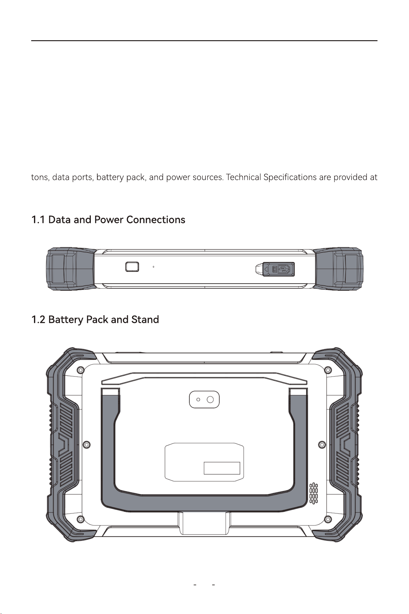
1.1 Data and Power Connections...........................................................................................................1
1.2 Batte Pack and Stand.......................................................................................................................1
1.3 Power Sources........................................................................................................................................2
1.4 Internal Batte Pack............................................................................................................................2
1.5 AC Power Supply...................................................................................................................................2
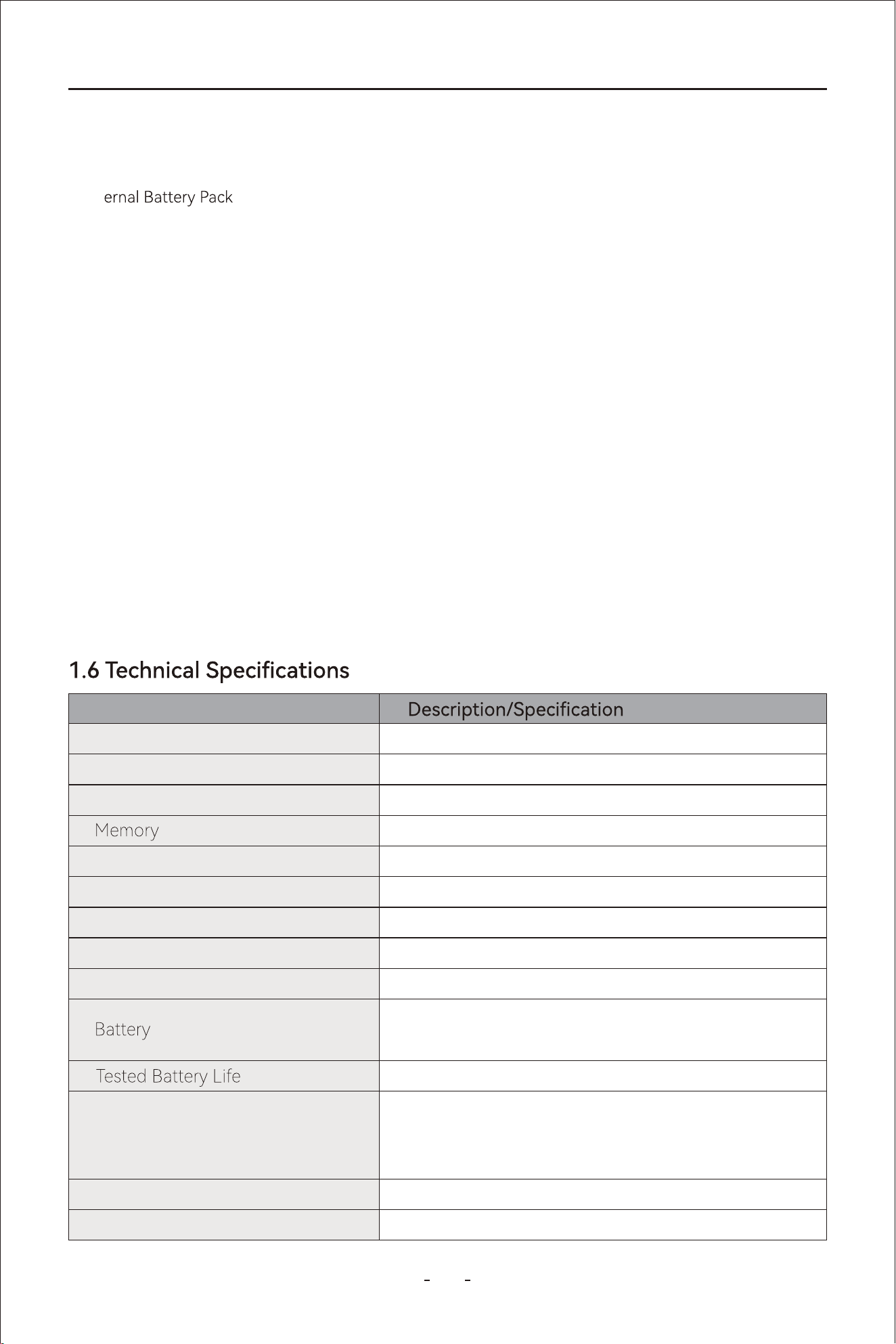
1.6 Technical Specications......................................................................................................................2
1.7 What's In The Box..................................................................................................................................3
1. INTRODUCTION...................................................................................1
2.1 Turning On...............................................................................................................................................4
2.2 Turning O...............................................................................................................................................4
2.3 Emergency Shutdown.........................................................................................................................4
3. GET TO KNOW THE DIAGNOSTIC TOOL........................................4
2. GETTING STARTED.............................................................................3
3.1 Diagnostic Screen Layout & Diagnostic Screen Icons............................................................5
3.2 Diagnostic Screen Layout..................................................................................................................5
3.3 Diagnostic Screen Icons......................................................................................................................5
3.3.1 Auto Scan......................................................................................................................................5
3.3.2 Manual Diagnosis.......................................................................................................................5
3.3.3 Special Functions........................................................................................................................5
3.3.4 Repo..............................................................................................................................................6
3.3.5 Updates..........................................................................................................................................6
3.3.6 More.................................................................................................................................................6
3.3.7 Settings...........................................................................................................................................6
3.3.8 Remote Control...........................................................................................................................6
3.3.9 Seice Center..............................................................................................................................6
3.4 Hidden Toolbar Menu, Main Screen Layout & Main Screen Icons.....................................6
3.4.1 Hidden Toolbar Menu...............................................................................................................7
3.5 Main Screen Layout..............................................................................................................................7
3.6 Main Screen Icons..................................................................................................................................7
3.6.1 Calender.........................................................................................................................................7
3.6.2 Camera............................................................................................................................................8
3.6.3 Contacts..........................................................................................................................................9
3.6.4 Clock.................................................................................................................................................9
3.6.5 Email..............................................................................................................................................10
3.6.6 Music.............................................................................................................................................10
3.6.7 Sound Recorder.........................................................................................................................11
3.6.8 Calculator.....................................................................................................................................11
3.6.9 ES File Explorer..........................................................................................................................12
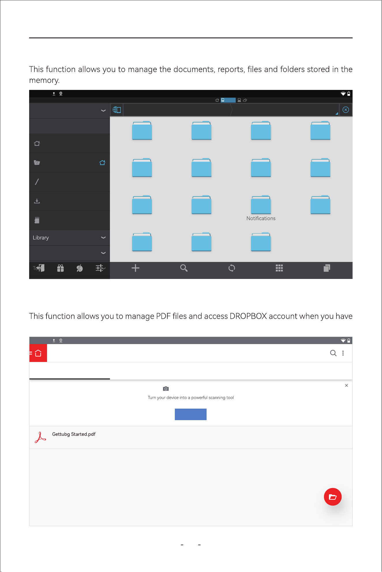
3.6.10 Adobe Acrobat........................................................................................................................12
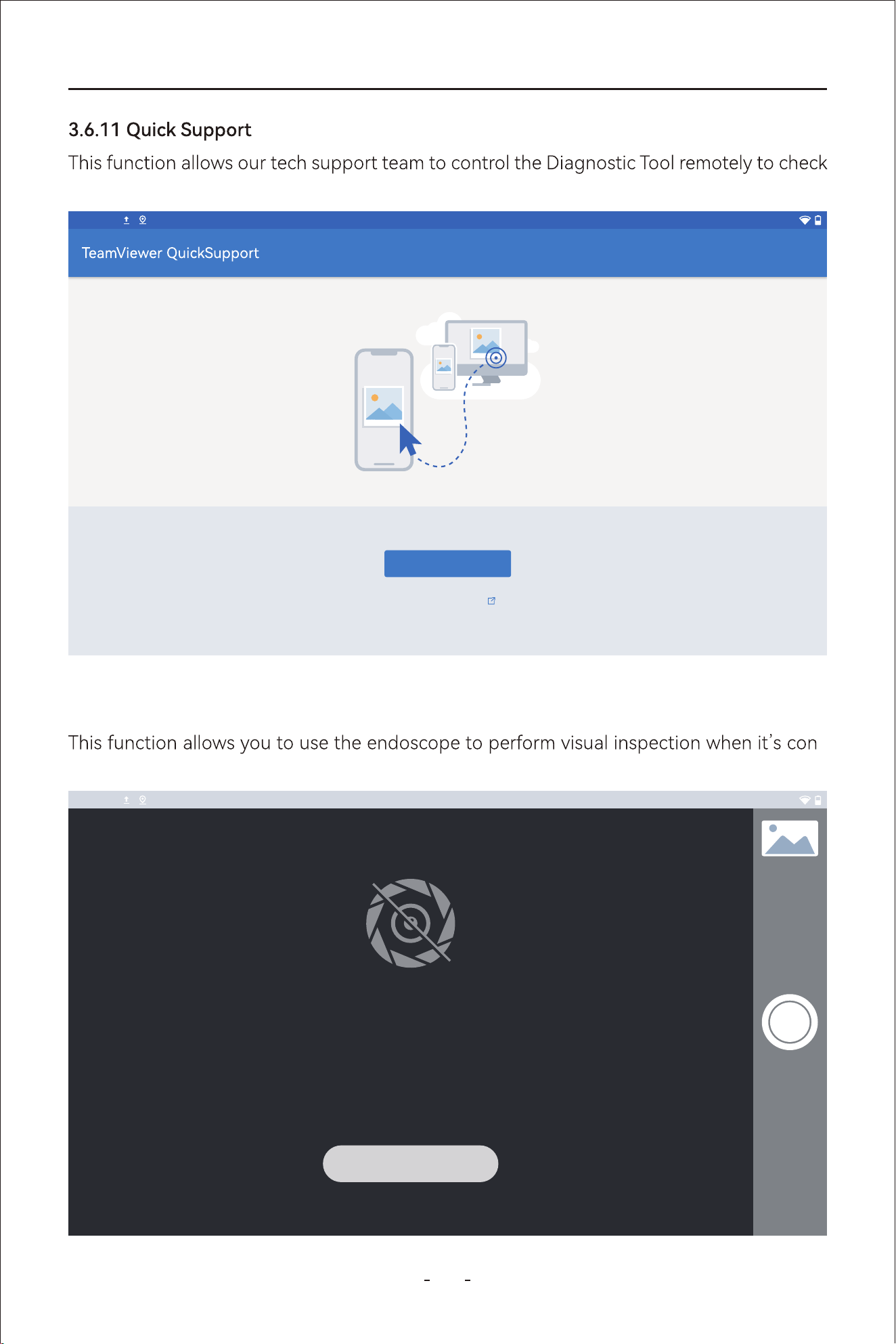
3.6.11 Quick Suppo..........................................................................................................................13
3.6.12 Endoscope................................................................................................................................13

Table of Contents
3.6.13 Settings......................................................................................................................................14
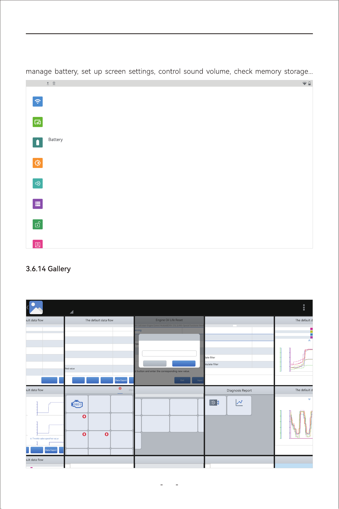
3.6.14 Galle........................................................................................................................................14
3.6.15 Video...........................................................................................................................................15
3.6.16 Explorer......................................................................................................................................15
3.6.17 Chrome.......................................................................................................................................16
3.8 Red-Green Color Blindness Color Correction Mode.............................................................17
3.7 Connect to USB Type-C Po for Data Transfer......................................................................16
3.9 VCI Box....................................................................................................................................................18
3.10 FCA AutoAuth - SGW......................................................................................................................19
3.11 Topology Mapping...........................................................................................................................19
3.12 Pre/Post Scan.....................................................................................................................................19
4. How to Diagnose Vehicles...............................................................20
4.1 My Vehicles............................................................................................................................................20
4.1.1 Compatibility Check................................................................................................................21
4.2 Software Program Version...............................................................................................................22
4.3 Demo Program......................................................................................................................................22
4.4 Trial Mode...............................................................................................................................................23
4.5 Wi-Fi Connection.................................................................................................................................23
4.6 Product Activation...............................................................................................................................23
4.7 Connecting the VCI Box....................................................................................................................28
4.8 Diagnose Vehicles...............................................................................................................................28
4.8.2 Manual Diagnosis.....................................................................................................................29
4.8.1 Auto Scan....................................................................................................................................29
4.8.3 Automatic Detection...............................................................................................................29
4.8.4 Manual Selection......................................................................................................................30
4.8.5 Automatic Scan.........................................................................................................................30
4.9 Submit Feedback.................................................................................................................................30
4.10 CAN Fast Scan....................................................................................................................................31
4.11 System Selection...............................................................................................................................31
4.12 Diagnostics..........................................................................................................................................31
4.12.1 Read Codes..............................................................................................................................31
4.12.2 Clear Codes..............................................................................................................................32
4.12.3 DTC Erased While Fault Remains....................................................................................32
4.12.4 DTC Erased and Fault Fixed - Histo Code...............................................................32
4.12.5 DTC Erased and Fault Fixed - Histo Cleared..........................................................33
4.12.6 PID Data.....................................................................................................................................33
4.12.7 PID Data List............................................................................................................................33
4.12.8 Individual PID Data Graphing............................................................................................34
4.12.9 Individual PID Data in Analog Dashboard...................................................................34
4.12.10 Set Maximum & Minimum Value Alarms....................................................................35
4.12.11 Zoom In & Zoom Out & View In Full Screen.............................................................36
4.12.12 Custom Up to 8 PID Data.................................................................................................36

Table of Contents
5. OBDII/EOBD.......................................................................................52
4.12.13 Individual Graphing for Up to 8 PID Data.................................................................38
4.12.14 8-In-1 Graphing..................................................................................................................38
4.12.15 Fold & Unfold PID Data Name.......................................................................................39
4.13 Full System Diagnostic Repo.....................................................................................................48
4.12.16 Data Recording & Playback............................................................................................40
4.12.17 Expo Data as CSV & Data View..................................................................................41
4.12.18 Data View................................................................................................................................42
4.12.19 Expo CSV File to a PC.....................................................................................................44
4.12.20 Share CSV le via Bluetooth...........................................................................................45
4.12.21 Freeze Frame........................................................................................................................46
4.12.22 Active Tests(Bi-Directional Controls)..........................................................................47
4.12.24 Exiting Diagnostics.............................................................................................................48
4.12.23 Special Functions................................................................................................................47
4.12.25 To Exit the Diagnostics.....................................................................................................48
4.14 Fault Code Repo.............................................................................................................................50
4.15 Diagnostic Speed..............................................................................................................................51
4.16 Integrated Module............................................................................................................................51
5.1 OBDII Protocols....................................................................................................................................53
5.2 Basic Operations..................................................................................................................................53
5.3 Auto Scan & Protocol Selection.....................................................................................................54
5.3.1 Auto Scan....................................................................................................................................54
5.3.2 Protocol Selection....................................................................................................................54
5.3.3 Help................................................................................................................................................54
5.4 10 Modes of OBDII..............................................................................................................................54
5.5 Connecting the Main Cable.............................................................................................................55
5.6 OBDII/EOBD Menu..............................................................................................................................55
5.6.1 Read Trouble Code..................................................................................................................55
5.6.2 Generic & Manufacturer-Specic Codes.........................................................................56
5.6.1.1 Read Trouble Code.......................................................................................................56
5.6.1.2 Pending Codes................................................................................................................56
5.6.1.3 Permanent Codes..........................................................................................................56
5.6.3 Permanent Codes......................................................................................................................57
5.6.4 Clear Trouble Code(Mode $04)...........................................................................................58
5.6.5 Live Data(Mode $01)...............................................................................................................58
5.6.6 Read Freeze Frame(Mode $02)...........................................................................................58
5.6.7 I/M Readiness(Smog Check).................................................................................................59
5.6.3.2 Second DTC character.................................................................................................57
5.6.3.1 First DTC Character.......................................................................................................57
5.6.3.3 Third DTC character......................................................................................................58
5.6.3.4 Fouh and Fifth DTC Character...............................................................................58

Table of Contents
5.6.8 O2S Monitoring Test(Mode $05)................................................................................................61
5.6.7.1 Since DTCs Cleared..............................................................................................................60
5.6.7.2 This Driving Cycle..................................................................................................................60
5.6.9 On-Board Monitor Test (Mode $06).........................................................................................62
5.6.10 Component Test(Mode $08)......................................................................................................62
5.6.11 Read Vehicle Information(Mode $09)....................................................................................62
6. Special Functions & Maintenance Seices..................................63
6.1 Oil Reset..................................................................................................................................................63
6.2 EPB............................................................................................................................................................66
6.3 SAS............................................................................................................................................................68
6.4 BMS Reset...............................................................................................................................................70
6.5 Injector Coding.....................................................................................................................................72
6.6 TPMS Reset............................................................................................................................................75
6.7 ABS Bleeding.........................................................................................................................................79
6.8 Power Balance......................................................................................................................................83
6.9 Seat Calibration....................................................................................................................................83
6.10 EEPROM................................................................................................................................................84
6.11 Language Change............................................................................................................................84
6.12 Transpo Mode.................................................................................................................................84
6.13 Control Unit Reset............................................................................................................................84
6.14 Throttle..................................................................................................................................................84
6.15 Rain/Light Sensor..............................................................................................................................84
6.16 A/F Reset..............................................................................................................................................84
6.17 HV Batte............................................................................................................................................84
6.18 Gearbox Match...................................................................................................................................84
6.19 Speed Limit..........................................................................................................................................85
6.20 Crank Sensor Relearn......................................................................................................................85
6.21 Clutch Adaption.................................................................................................................................85
6.22 Stop/Sta Reset.................................................................................................................................85
6.23 FRM Reset............................................................................................................................................85
6.24 EGR Relearn.........................................................................................................................................85
6.25 A/C Relearn..........................................................................................................................................85
6.26 Headlight..............................................................................................................................................85
6.27 SRS..........................................................................................................................................................86
6.28 Windows Initialization.....................................................................................................................86
6.29 VGT Relearn.........................................................................................................................................86
6.30 Coolant Bleeding...............................................................................................................................86
6.31 Suspension...........................................................................................................................................86
6.32 Airbag Reset........................................................................................................................................86
6.33 Tire Size Reset.....................................................................................................................................86
6.34 AdBlue Reset........................................................................................................................................87
6.35 ECU Conguration.............................................................................................................................87

6.36 Sunroof Initialization........................................................................................................................87
6.37 Camshaft Learning...........................................................................................................................87
6.38 TCM Oil Reset.....................................................................................................................................87
Table of Contents
9. More.....................................................................................................92
8. Software Updates.............................................................................91
7.3 USB Setting............................................................................................................................................89
7.4 Sound & Display...................................................................................................................................90
7.5 About........................................................................................................................................................90
9.2 User Manual...........................................................................................................................................92
9.3 Vehicle Coverage.................................................................................................................................92
9.1 Prole........................................................................................................................................................92
10. Other Settings.................................................................................93
11. Seice Center...............................................................................103
10.1 Email Settings.....................................................................................................................................93
10.2 Delete Email Account......................................................................................................................97
10.3 Printing Settings................................................................................................................................99
10.4 Printer with WIFI Direct...............................................................................................................................................103
10.3.2 Download the Corresponding APK File.......................................................................99
10.3.1 Checklist for Installing Printing Seice........................................................................99
11.1 Remote Control...............................................................................................................................105
11.2 Schedule a Remote Control........................................................................................................106
11.3 Data Logging...................................................................................................................................107
11.4 App Logging.....................................................................................................................................107
11.6 FAQ Database..................................................................................................................................107
11.7 Training Center................................................................................................................................107
11.8 User Programs.................................................................................................................................107
11.9 Corporate Purchase.......................................................................................................................108
11.10 Inventers and Testers Program...............................................................................................108
11.11 U-Fluncer Program......................................................................................................................108
11.12 Become a Distributor..................................................................................................................108
7. Settings...............................................................................................88
7.1 Language................................................................................................................................................88
7.2 Unit............................................................................................................................................................88

Table of Contents
13. Contact Us.....................................................................................109
14. Appendix........................................................................................111
14.1 Navigation Path Quick Check....................................................................................................111
14.2 Terms & Terminology Quick Check.........................................................................................111
14.3 FAQs....................................................................................................................................................112
12. Warranty........................................................................................109
1
a
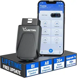
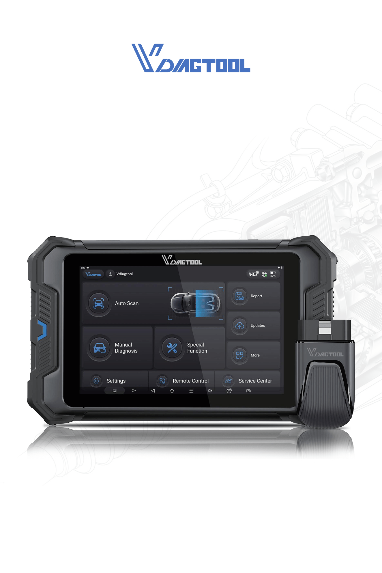
vehicle to retrieve diagnostic trouble codes (DTCs), access data stream information, and
command active tests(bi-directional control tests). Various vehicle control systems, such as
engine, transmission, and anti-lock brake system (ABS), SRS(Airbag) system, Chassis, Body
and etc are readily diagnosed using this Diagnostic Tool. The Diagnostic Tool is capable of
graphing up to eight(8) live data parameters on a single screen, and also includes ECU
information.
This chapter introduces the basic features of the Diagnostic Tool, including the control but-
the end of this chapter.
1. Introduction
VD80 BT Diagnostic Tool
The VDlAGTOOL VD80 BT Diagnostic Tool inteaces with the electronic control unit(ECU) of
2
VD80 BT Diagnostic Tool
Item
8 Inch Touch Screen, 1280×800 Resolution
Android 10.0
Quad-Core Processor 1.5GHz
4G RAM, 64G ROM
Bluetooth 4.1, Wi-Fi(2.4GHz & 5Ghz), Type-C
Gravity Accelerometer/Ambient Light Sensor
Microphone
Built-In Speaker
8 Mega Pixel
3.5 hours
9V-36V
10.39×6.06×1.39 in(264*154*35.5mm)
DC 7.3V Rechargeable Li-ion batte, 5000mAh
Input: 5.0V 3.0A
For AC Adapter Input: 100-240V
Adapter Output: 5.0V 3.0A
Display
Operating System
Processor
Connectivity
Sensor
Audio
Speaker
Camera
Operating Voltage
Dimensions
Power Supply
● Int
● AC Power Supply
The VCI Box is powered by connecting it to the vehicle OBDII po.
VDIAGTOOL VD80 BT Diagnostic Tool can receive power from either of the two sources:
1.3 Power Sources
The Diagnostic Tool can be powered from a standard AC outlet using the AC power supply.
The connector on the end of the output cable of the AC power supply attaches to the DC
power supply input jack on top of the Diagnostic Tool. Use only the AC power supply pro-
vided.
1.5 AC Power Supply
1.4 Internal Batte Pack
The VDIAGTOOL VD80 BT Diagnostic Tool can be powered from the internal rechargeable
batte pack. A fully charged batte provides sucient power for about 3.5 hours of con-
tinuous operation.
Batte charging occurs when the Diagnostic Tool is connected to the AC Power Supply and
to a live AC power source.
3
VD80 BT Diagnostic Tool
Item
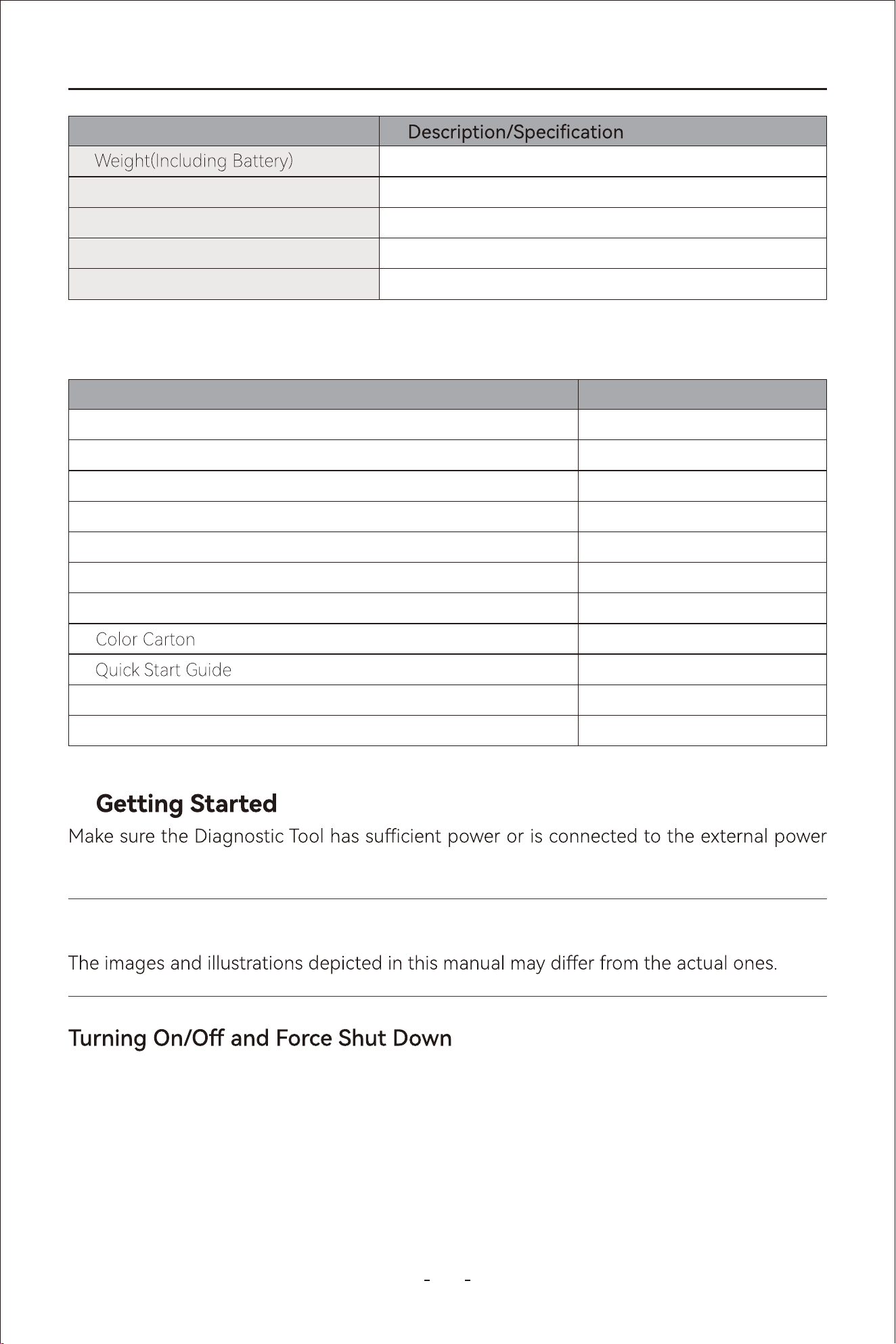
2.34lbs(1.06kg)
4.96lbs(2.25kg)
32°F ~ 104°F (0°C ~ 40°C)
14~122°F (-10~50°C)
<90%
Gross Weight
Operating Temp Range(Ambient)
Storage Temp(Ambient)
Operating Humidity
Name QTY
VD80 BT Diagnostic Tool
VD80 BT VCI Box
Type-C to Type-A Adapter (Connecting to PC)
Type-C to Type-C Charger Cable
Charger Adapter US Standard
Charger Adapter EU Standard
Charger Adapter UK Standard
Packing List
Hard Case
1
1
1
1
1
1
1
1
1
1
1
1.7 What’s In The Box
supply (see Power Sources on page 2).
2.
Note:
The following sections describe how to turn the VDIAGTOOL VD80 BT Diagnostic Tool on
and o and how to peorm an emergency shutdown.
4
VD80 BT Diagnostic Tool
Press and hold the power button on the top right of the Diagnostic Tool for 3(three) sec-
-
nected to an AC power supply.
before you turn it on.
2.1 Turning On
Press and hold the power button again for over 3(three) seconds and the Diagnostic Tool
above. The emergency shutdown procedure should only be used If the Diagnostic Tool
does not respond to navigation or control buttons or exhibits erratic operation. To force an
2.3 Emergency Shutdown
This chapter describes the layout of the main diagnostic screen, main diagnostic screen
icons, main screen and main screen icons of the android tablet.
3. Get to Know the Diagnostic Tool
IMPORTANT:
Using the emergency shutdown procedure while communicating with the vehicle ECM may
lead to ECM problems on some vehicles.
All vehicle communication must be terminated BEFORE the Diagnostic Tool. A
warning message displays if you attempt to turn the Diagnostic T
-
ing with the vehicle. Forcing a shut down while communicating may lead to ECM
problems on some vehicles. Never disconnect VCI Box when the Diagnostic Tool is com-
municating with the vehicle ECM.
5
VD80 BT Diagnostic Tool
When the Diagnostic Tool is turned on, it will run the diagnostic program automatically and
you will see the diagnostic screen when the program is initiated. The Diagnostic Tool uses
hidden toolbar at the bottom of diagnostic tablet and swipe up from the bottom will bring
up the toolbar for 3 (three) seconds. The section below will show you the diagnostic screen
layout and toolbar icons.
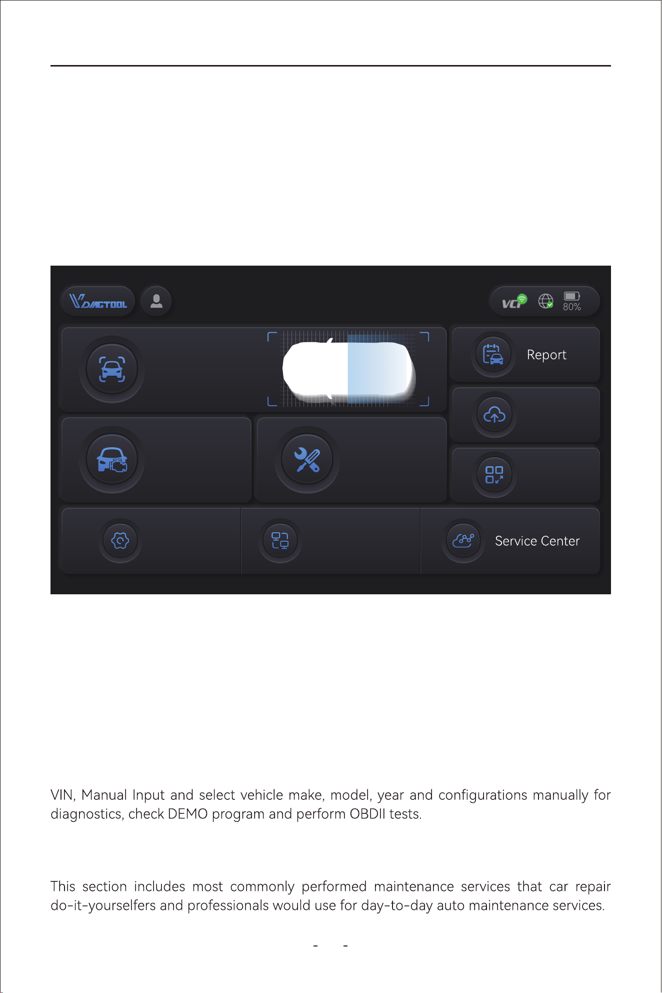
3.1 Diagnostic Screen Layout & Diagnostic Screen Icons
3.3.1 Auto Scan
Automatically detects and decodes the VIN number, and proceed to comprehensively scan
all available vehicle electronic control modules for diagnostics.
3.3.2 Manual Diagnosis
Click this icon will bring up the diagnostic menu where you can navigate the vehicle by Auto
3.3.3 Special Functions
3.3 Diagnostic Screen Icons
3.2 Diagnostic Screen Layout
Updates
More
Manual
Diagnosis
Auto Scan
Special
Function
Settings Remote Control
VDIAGTOOL
6
VD80 BT Diagnostic Tool
Swipe up from the bottom of the touch screen will un-hide the toolbar for 3 seconds and
clicking the home button of the hidden toolbar will bring up the main screen of the diag-
nostic tablet. The sections below describes what’s the main screen layout looks like and
what the icons are for.
3.4 Hidden Toolbar Menu, Main Screen Layout & Main Screen Icons
3.3.5 Updates
This section allow you to download diagnostic software programs individually or in batch.
This section includes diagnostic repos, data playback and data view functions, etc.
This section allows you to set the user account and the workshop prole if applicable, ch-
eck subscription period, check rmware information, use the endoscope and check user
manual in PDF.
3.3.6 More
3.3.7 Settings
This section allows you to set the language of the diagnostic software, units of measur-
ement, USB mode and OS settings, adjust volume and brightness level of the android ta-
blet, and check App version, OS version, Serial Number of the Diagnostic Tool and VCI nu-
mber.
3.3.8 Remote Control
Clicking this icon will run the TeamViewer for remote control assistance. Make sure the
TeamViewer is in “ready to connect” status before the scheduled remote assistance
appointment. The TeamViewer ID will show on the right side and the connection status at
the bottom left.
This section introduces the contact methods and social media accounts where you can get
Note:
This section does not include advanced features like resets, relearns, matchings, adapta-
tions and initializations under diagnostic job menu. And functions with the same name may
under diagnostic job menu.
7
VD80 BT Diagnostic Tool
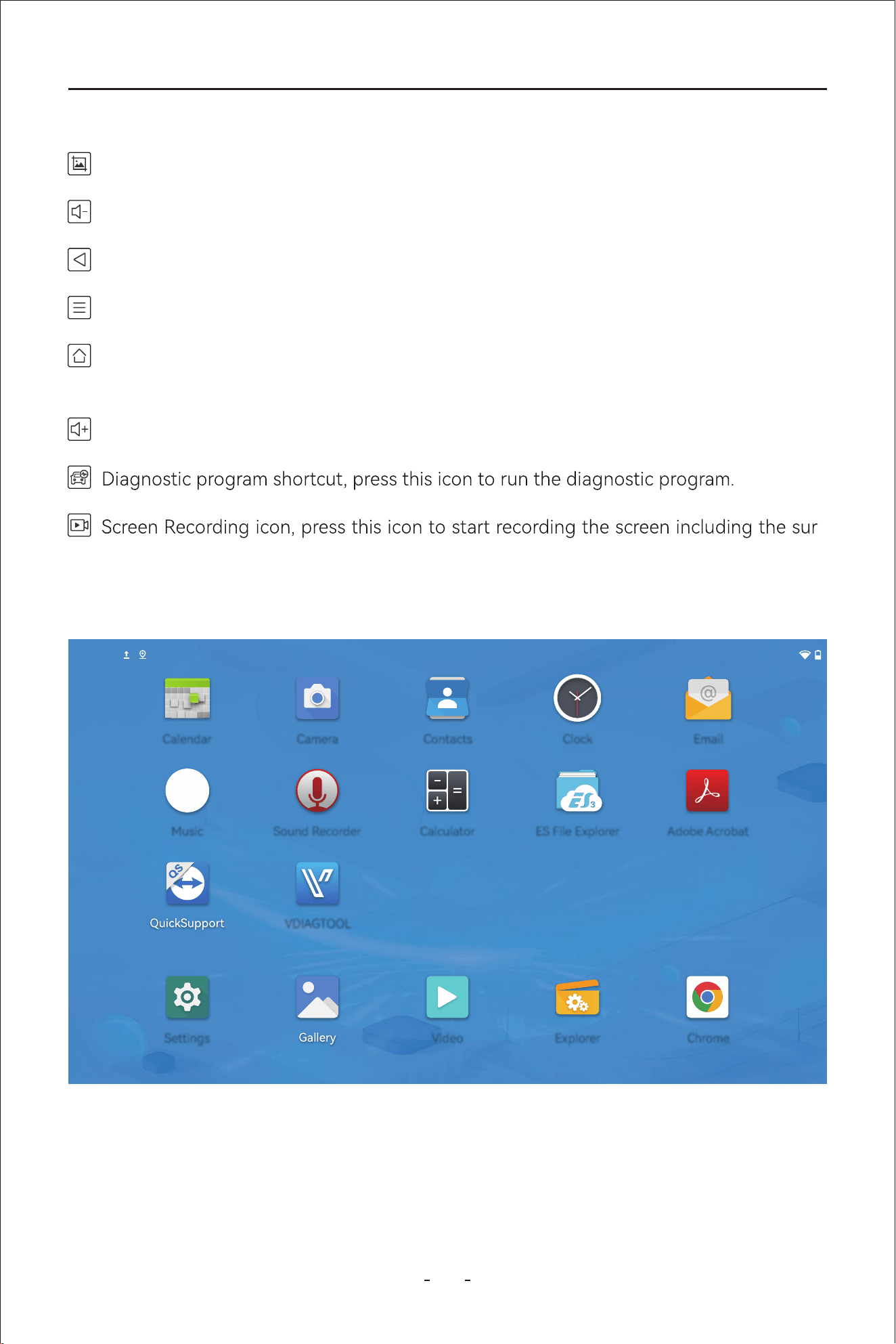
3.4.1 Hidden Toolbar Menu
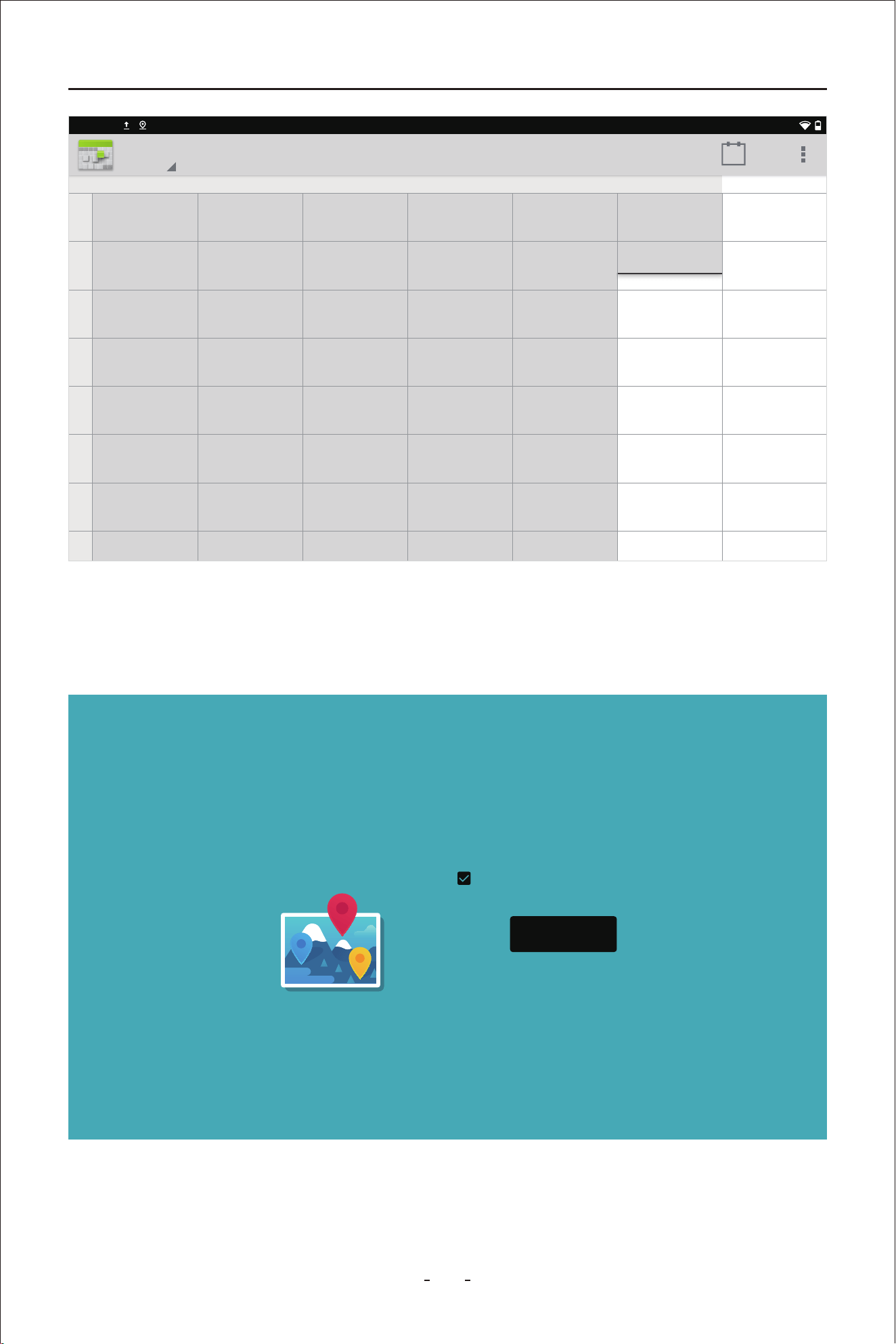
3.6.1 Calender
This function displays the calender in day, week and month.
3.6 Main Screen Icons
3.5 Main Screen Layout
Take a screenshot on what’s on the screen.
Volume Down icon, press to decrease the volume of the speaker of the android tablet.
Volume Up icon, press to raise the volume of the speaker of the android tablet.
-
rounding sound. Press the icon again to end the screen recording process.
Home icon, press to go to the main screen of the android tablet.
Task List icon, press this icon to view all ongoing tasks. Swipe up the respective task
screen to kill the task.
Press to back one step from the current menu.
2:40PM
EmailCalendar Camera Contacts Clock
Music Sound Recorder
VDIAGTOOL
Calculator ES File Explorer Adobe Acrobat
Settings Video Explorer Chrome
8
VD80 BT Diagnostic Tool
3.6.2 Camera
This function activates the camera at the back of the Diagnostic Tool so that you can take
pictures of the vehicle problem.
23
SAT
22
FRI
21
THU
20
WED
19
TUE
18
MON
17
SUN
2:40PM
Week
22
TODAY
1
PM
2
3
4
5
6
7
8
Remember photo
locations ?
Tag your photos and videos with
the locations where they’re taken.
NEXT
9
VD80 BT Diagnostic Tool
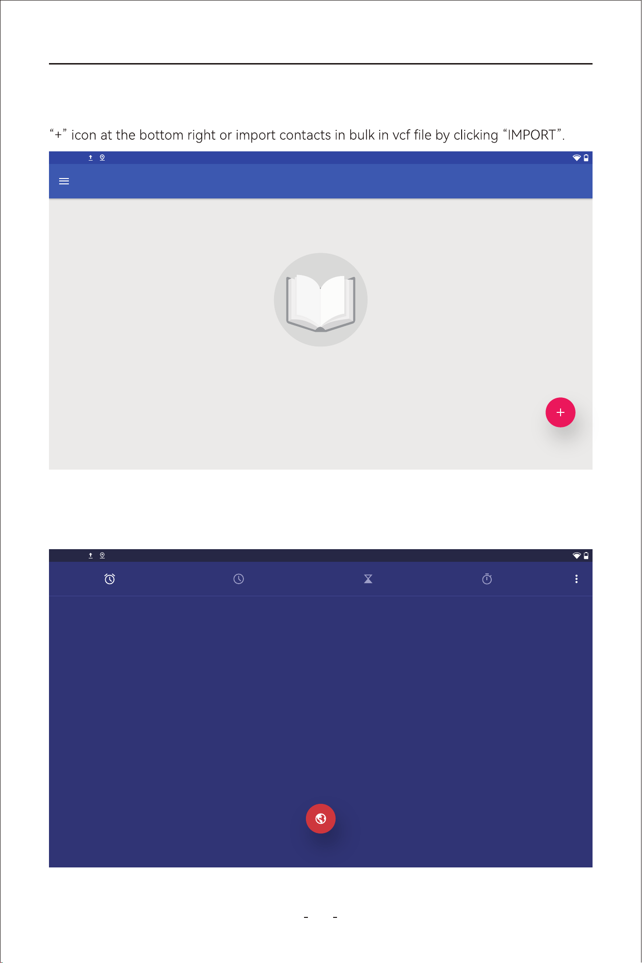
3.6.3 Contacts
This function allows you to manage your contact information, add a new contact by clicking
3.6.4 Clock
This function allows you to set alarms, set timer, to use the stopwatch or the clock.
2:40PM
Contacts
Your contacts list is empty
IMPORT
2:40PM
ALARM CLOCK TIMER STOPWATCH
2:40
PM
FRI,MAR 22
10
VD80 BT Diagnostic Tool
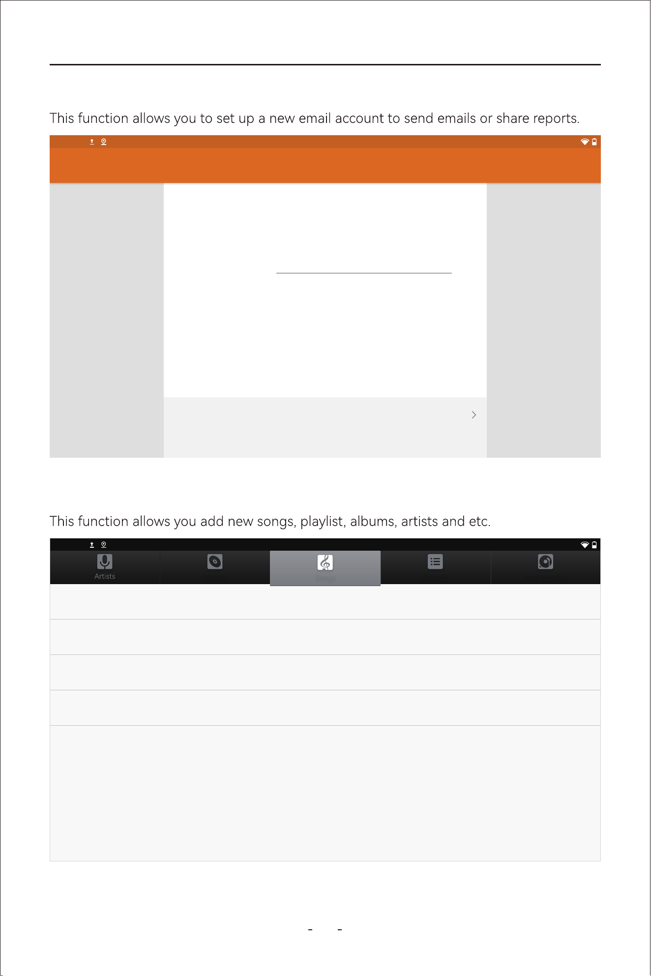
3.6.5 Email
3.6.6 Music
Email account
You can set up your account in just a few steps.
Email address
MANUAL SETPUP NEXT
Account setup
2:40PM
2:40PM
Albums Playlists Now playing
Songs
2 Kings (ft. D. LAC)
King Loki
4:21
A Day With Me
Luna Is A Bep
3:08
Makin Papers (ft. 芭比兽)(Cover: Lupe Fiasco)
King Loki
3:52
One Piece × Pirates of The Caribbean (Covrer)
Samuel Kim
3:36
11
VD80 BT Diagnostic Tool
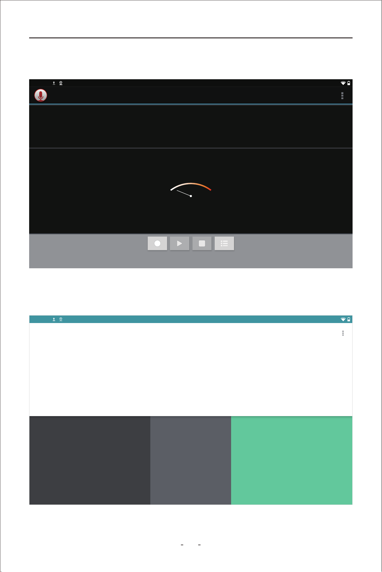
3.6.7 Sound Recorder
This function allows you to record a voice message.
3.6.8 Calculator
This function brings up calculator.
2:40PM
Record your message
00:00
7 8 9 ÷
DEL
4 5 6 ×
1 2 3 -
. 0 + =
INV
DEG %
sin
cos
log
tan
In
!
e
π
( )
√
>
2:40PM
RAD
12
VD80 BT Diagnostic Tool
3.6.9 ES File Explorer
3.6.10 Adobe Acrobat
logged into Adobe account and DROPBOX account.
Fast Access
Local
2:40PM
sdcard/
Favorite
Local
Network
Tools
Homepage
Home
Device
Download
0
Exit Recomme... Theme Settings
Refresh View WindowsSearchNew
Alarms amap Android backups
bluetooth DCIM Diagnosis Download
Movies Music Pictures
Podcasts Records Ringtones
2:40PM
My Documents
RECENT LOCAL DOCUMENT CLOUD DROPBOX
New: Adobe Scan app
with free text recognition super powers.
Learn More
02:54 PM 53.0 KB
13
VD80 BT Diagnostic Tool
possible problems with the Diagnostic Tool or help you with navigation path etc.
3.6.12 Endoscope
-
nected to to the Diagnostic Tool.
2:40PM
I accept the EULA and the DPA.
AGREE AND CONTINUE
Privacy Policy
Please connect the endoscope
Please connect the endoscoe
2:40PM
8/236
70: Cause for cancellation
71: Throttle valve position 1
72: Throttle valve position 2
74: Result test Evap. Emission (EVAP) Canister Purge Reg. Valve
VW V14.30> Automatic Detection> 01 - Engine electronics> Live data
Name
8/8
VW V14.30> Automatic Detection> 01 - Engine electronics> Live data
0000
0.00
0001 0002
18.00
36.00
54.00
72.00
90.00
1:Throttle valve position (absolute)
0000
000
0001 0002
14.00
28.00
42.00
56.00
70.00
3: Throttle valve position, normed
4.00
5.00
5: Accelerator pedal, sensor voltage 2
VW V14.30> Automatic Detection> 01 - Engine electronics> Live data
Throttle valve position (absolute)
Throttle valve position, normed
Accelerator pedal, sensor voltage2
Throttle valve position 1
80.00
64.00
48.00
32.00
16.00
90.00
72.00
54.00
36.00
18.00
0.00
5.00
4.00
3.00
2.00
1.00
70.00
56.00
42.00
28.00
14.00
0.00
14
VD80 BT Diagnostic Tool
3.6.13 Settings
This function allows you to set up android tablet settings, including Wi-Fi connections,
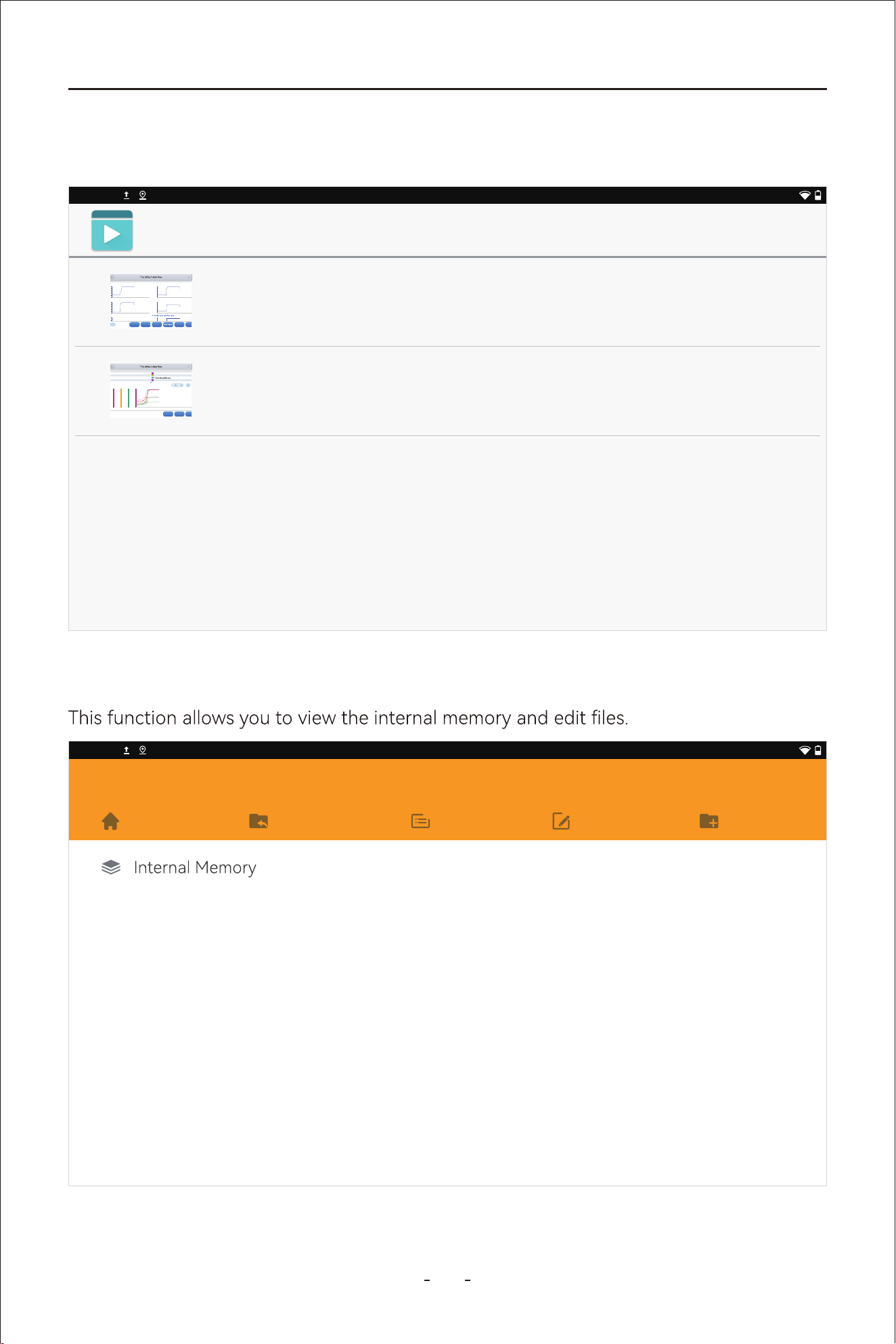
This function allows you to view the screenshots, images taken by the camera and screen
recordings.
2:40PM
Network & internet
Wi-Fi, data usage, and hotspot
Connected devices
Bluetooth, printing
0% - charging
Display
Wallpaper, sleep, font size
Sound
Volume, Do Not Disturb
Storage
37% used - 40.28 GB free
Security
Screen lock
Accounts
No accounts added
Screenshot
Grid view
14.9
1: Throttle valve position (absolu
te)
%
16.5
2: Acceleratir pedal position
%
3.9
3: Throttle valve position, normed
%
0.7550
4: Accelerator pedal, sensor
voltage 1
V
0.3793
5: Accelerator pedal, sensor
voltage 2
V
3.9
%
0.7413
7: Throttle valve nosition 1
V
Name
Value
Unit
PauseRecord
CombineGraphDisplay All
8/8
31%
VW V14.30> Automatic De
tection> 01 - Engine electronics> Live data
PauseCustom
Cancel Selected
0
70: Cause for cancellation
0.8548
71: Throttle valve position 1
V
0
16.9
72: Throttle valve position 2
%
1
0
74: Result test Evap. Emission (EVAP) Canister Purge
Reg. Valve
VW V14.30> Automatic Detection> 01 - Engine electronics> Liv
e data
Value
Unit
31%
PauseRecord
Combine
ListDisplay All
31%
VW V14.30> Automatic Detection> 01 - Engine electronics> Liv
e data
0004 0005 0006 0007 0008 00
09 0010
1:Throttle valve position (absolute) 83.5 %
0000
0.00
0001 0002 0003 0004 0005
0006 0007 0008 0009 0010
16.00
32.00
48.00
64.00
80.00
2:Accelerator pedal position
65.9 %
0004 0005 0006 0007 0008 00
09 0010
3: Throttle valve position, normed 55.7 %
0000
000
0001 0002 0003 0004 0005
0006 0007 0008 0009 0010
1.00
2.00
3.00
4.00
5.00
4: Accelerator pedal, sensor v
oltage 1 3.0447 V
5: Accelerator pedal, sensor voltage 2 1.4850 V
56.00
70.00
41.2 %
31%
VW V14.30> Automatic Detection> 01 - Engine electronics> Liv
e data
52.2 %
Accelerator pedal position
51.0 %
36.5
%
Accelerator pedal, sensor voltage 1
2.5494
V
Accelerator pedal, sensor voltage2
1.2778
V
36.9
%
2.5998
V
Throttle valve position 2
51.8
%
X
X1
Y
X1
70.00
56.00
42.00
28.00
14.00
5.00
4.00
3.00
2.00
1.00
0.00
90.00
72.00
54.00
36.00
18.00
5.00
4.00
3.00
2.00
1.00
0.00
Exit
VW V14.30> Automatic De
tection> 01 - Engine electronics> Live data
Throttle valve position (absolu
te)
52.2
%
Accelerator pedal position
Throttle valve position, normed
36.5
%
Accelerator pedal, sensor voltage 1
Accelerator pedal, sensor voltage2
1.2778 V
Throttle valve position 1
2.5998
V
Throttle valve position 2
X1
80.00
64.00
48.00
32.00
16.00
0.00
90.00
72.00
54.00
36.00
18.00
0.00
5.00
4.00
3.00
2.00
1.00
0.00
70.00
56.00
42.00
28.00
14.00
0.00
70.00
56.00
42.00
28.00
14.00
0.00
5.00
4.00
3.00
2.00
1.00
0.00
90.00
72.00
54.00
36.00
18.00
0.00
5.00
4.00
3.00
2.00
1.00
0.00
0000 0001 0002
0003 0004 0005 0006
40356
Total distance (absolute value)
840
Revolution counter
23.00
Fuel level sensor, right
44.00
Total fuel level of both fuel level sensors (sum value)
50.00
Outside temperature sensor
DEMO V5.60> A
Name Value
Gener
al
Data
recording is turned on, pres
s again to end data recording
0.0s
14.50
7.052s 14.104s 21.156s 28.208s 35.26s 43.312s 49.364s
56.416s
63.468s 70.52s
28.62
42.75
56.88
71.00
Throttle valve position (absolute) | %
0.0s
14.50
7.052s 14.104s 21.156s 28.208s 35.26s 43.312s 49.364s
56.416s
63.468s 70.52s
26.95
39.00
51.05
63.10
Accelerator pedal position | %
31%
Data View
VW_20240124002124_17060
84557523.csv
x-axis
22.75 s
y-axis
Accelerator pedal position
49.0
Throttle valve position
34.9
Accelerator pedal
X : 22.75 (s)
Y : 40.8 | %
X : 22.75 (s)
Y : 49.0 | %
2024-03
VW_20240124001915
VW_20240124002124_
2024-03-24 002237
VW_20240124001915
VW_20240124002124_
2024-03-24 002337
2024-02
VW_20240124001915
VW_20240124002124_
2024-02-24 000526
31%
Data View
0.0s
14.50
7.052s 14.104s 21.156s 28.208s 35.26s 43.312s 49.364s
56.416s
63.468s 70.52s
28.62
42.75
56.88
71.00
Throttle valve position (absolute) | %
0.0s
14.50
7.052s 14.104s 21.156s 28.208s 35.26s 43.312s 49.364s
56.416s
63.468s 70.52s
26.95
39.00
51.05
63.10
Accelerator pedal position | %
31%
Data View
VW_20240124002124_17060
84557523.csv
x-axis
0 s
y-axis
Accelerator pedal position
16.5
Throttle valve position
5.9
Accelerator pedal
31%
Data Playback Data View
31%
OBDII V21.51
OBDII V21.51> AUTO SCAN
Clear Trouble
Code(Mode04)
Read Trouble
Code(Model03/07/0A
)
Read ECU
Information(Mode0
9)
On-Board Monitor
Test(Mode06)
I/M
Readiness(Mode
01)
Live
Data(Mode 01)
R
ead Freeze
F
rame(Model02)
Component
Test(Mode08)
O2S monitoring
Test(Mode05)
My vehicles Europe America Asia
Diagnosis for
V6.30
DEMO
Diagnosis for
V12.40
ACURA
Diagnosis for
V5.35
DAEWOO
Diagnosis for
V8.41
DAIHATSU
Diagnosis for
V12.40
HONDA
Diagnosis for
V14.10
HYUNDAI
Diagnosis for
V5.18
HYUNDAICV
Diagnosis for
V13.80
INFINITI
Diagnosis for
V9.20
ISUZU
Diagnosis for
V14.10
KIA
Diagnosis for
V14.80
LEXUS
Diagnosis for
V13.70
MAZDA
Diagnosis for
V12.20
MITSSUBISSH
I
Diagnosis for
V13.81
NISSAN
Diagnosis for
Diagnosis for Diagnosis for Diagnosis for
Diagnosis for
Diagnosis for
V21.51
D
H
I
K
L
M
N
P
R
S
T
A
OK
InputExit
GM V13.90> 2018(J)> Buick>
LaCrosse> Engine Control Module(ECM)> 2.5L (LHN)> Special Functions> Re
set Functions
31%
Engine Oil Life Reset
Current value
%
*
Engine Oil Life Remaining
Min
%
*
New value (click to Input
to change the value)
%
*
Max
%
100
Please click the Input but
ton and enter the corresponding new value.
Engine Oil Life Reset
OKCancel
Engine Oil Life Remaining
100
Next step
DPF/GPF V7.20> DPF(Diesel oi
l)> Europe> VW> Auto scan> DPF regeneration
31%
1.6L
Regeneration duration
min
0.00
Carbon deposit
g
22.78
Rotating speed
rpm
781
Waste temperature upst
ream of turbocharger
degree C
143.41
degree C
143.20
degree C
112.38
Exit
VW V14.30> Automatic De
tection> 01 - Engine electronics> Live data
X1
80.00
64.00
48.00
32.00
16.00
0.00
90.00
72.00
54.00
36.00
18.00
0.00
5.00
4.00
3.00
2.00
1.00
0.00
70.00
56.00
42.00
28.00
14.00
0.00
70.00
56.00
42.00
28.00
14.00
0.00
5.00
4.00
3.00
2.00
1.00
0.00
90.00
72.00
54.00
36.00
18.00
0.00
5.00
4.00
3.00
2.00
1.00
0.00
0000 0001 0002
0003 0004 0005 0006
Pause
31%
%
V
%
%
0008 0009 0010
km
1/min
l
l
deg C
Unit
31%
Pause
31%
0008 0009 0010
15
VD80 BT Diagnostic Tool
3.6.15 Video
This function allows you to view the recorded screen recordings.
3.6.16 Explorer
2:40PM
Video
1645525052500.mp4
0000/0610 video/mp4
/storage/emulated/0/Movies/1645525052500.mp4 72M
1645525052501.mp4
0000/0510 video/mp4
/storage/emulated/0/Movies/1645525052501.mp4 65M
P
ause
RecordCombineListDisplay All
8/8
31%
VW V14.30>
Automatic Detection> 01 - Engine electronics> Live data
00
00
0.00
0001 0002 0003 0004 0005 0006 0007 0008 0009 0010
18.00
36.00
54.00
72.00
90.00
1:Throttle
valve position (absolute) 83.5 %
0000
0.00
0001 0002 0003 0004 0005 0006 0007 000800
09 0010
16.00
32.00
48.00
64.00
80.00
2:Accelerator pedal position 65.9
%
00
00
000
0001 0002 0003 0004 0005 0006 0007 0008 0009 0010
14.00
28.00
42.00
56.00
70.00
3: Throttle
valve position, normed 55.7 %
0000
000
0001 0002 0003 0004 0005 0006 0007 000800
09 0010
1.00
2.00
3.00
4.00
5.00
4: Accelerator pedal, sensor voltage 1 3.0447
V
4.00
5.00
5: Accele
rator pedal, sensor voltage 2 1.4850 V
56.00
70.00
41.2
%
P
ause
RecordExit
31%
VW V14.30>
Automatic Detection> 01 - Engine electronics> Live data
Thro
ttle valve position (absolute)
52.2
%
Accelerator pedal position
51.0
%
Thro
ttle valve position, normed
36.5 %
Accelerator pedal, sensor voltage 1
2.5494
V
Accele
rator pedal, sensor voltage2
1.2778
V
36.9
%
Thro
ttle valve position 1
2.5998 V
Throttle valve position 2
51.8
%
X
X1
Y
X1
80.00
64.00
48.00
32.00
16.00
0.00
90.00
72.00
54.00
36.00
18.00
0.00
5.00
4.00
3.00
2.00
1.00
0.00
70.00
56.00
42.00
28.00
14.00
0.00
70.00
56.00
42.00
28.00
14.00
0.00
5.00
4.00
3.00
2.00
1.00
0.00
90.00
72.00
54.00
36.00
18.00
0.00
5.00
4.00
3.00
2.00
1.00
0.00
0000 0001 0002 0003 0004 0005 0006 0007 0008 0009
0010
2:40PM
Explorer
Home LevelUp Multi Editor NewFolder
16
VD80 BT Diagnostic Tool
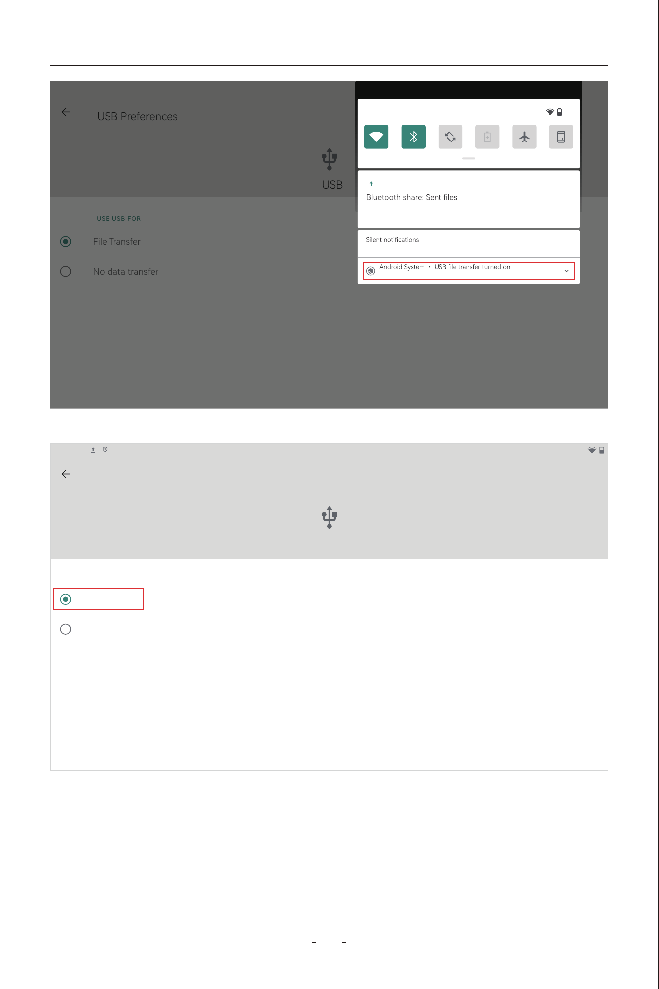
To enable data transfer between the Diagnostic Tool and a PC, please follow the steps
below:
Step 1: Connect the Diagnostic Tool to a PC through Type-C cable with one end into the
PC.
Step 2: Then swipe down from the upper right corner or the upper left corner on the Diag-
nostic Tool to bring up the drop down menu and click “Android System. Charging
this device via USB”.
Step 3: Change the option from “No data transfer” to “File Transfer”.
Step 4:
3.6.17 Chrome
This function activates preinstalled browser so that you can search fault codes and etc
online.
2:40PM
VDIAGTOOL
vdiagtool.com
Home
Products
Where to Buy
About Us
Check the device connected on the PC and click “VD80 BT” to check the les stored in the
internal memo of the Diagnostic Tool.
17
VD80 BT Diagnostic Tool
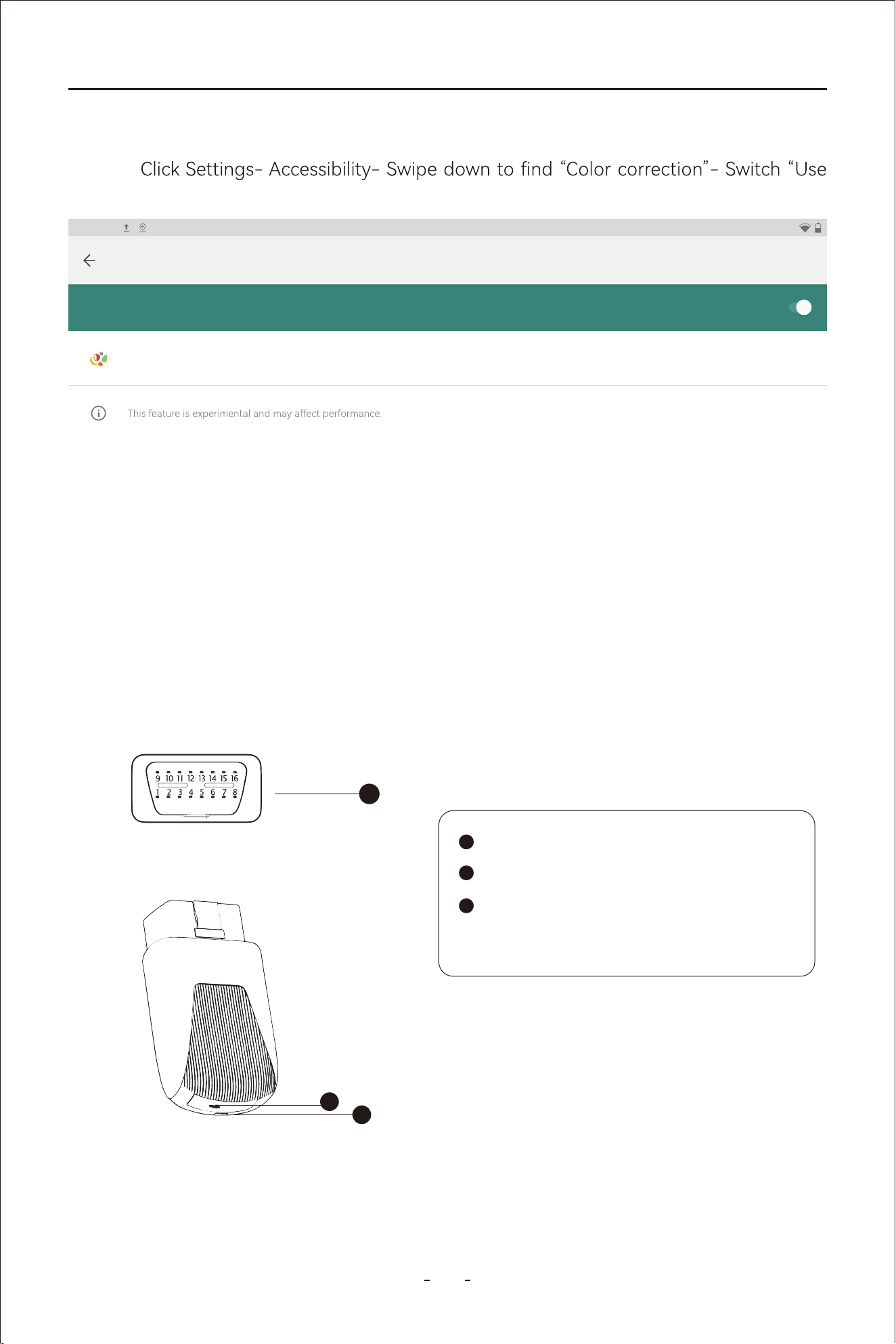
Step 1: Swipe up from the bottom and bring up the hidden menu.
Follow the steps below to set to red-green color blindness color correction mode:
3.8 Red-Green Color Blindness Color Correction Mode
USB Preferences
USB
USE USB FOR
File Transfer
No data transfer
12:28PM
50%
Bluetooth
4 successful, 0 unsuccessful.
CLEAR ALLManage
2:40PM
USB Preferences
USB
USE USB FOR
File Transfer
No data transfer
18
VD80 BT Diagnostic Tool
Step 2: Click home button to switch to main screen of android tablet.
Step 3:
color correction” to on position.
PRINT SERVICES
Use color correction
2:40PM
Color correction
Correction mode
Deuteranomaly (red-green)
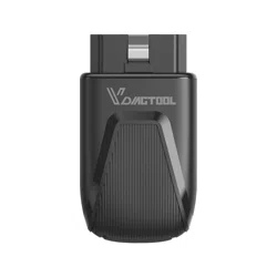
3.9 VCI Box
OBD Male Adapter
VCI Indicator
Type-C Po - Connect to Diagnostic
Tool via cable
The VCI Box communicates with the Diagnostic Tool via WiFi. The WiFi wireless connec-
tion provides faster transmission speed than Bluetooth, ensuring stable communication,
longer transmission distances, and higher data capacity, helping you achieve faster diag-
nostics.
2
3
1
1
2
3

19
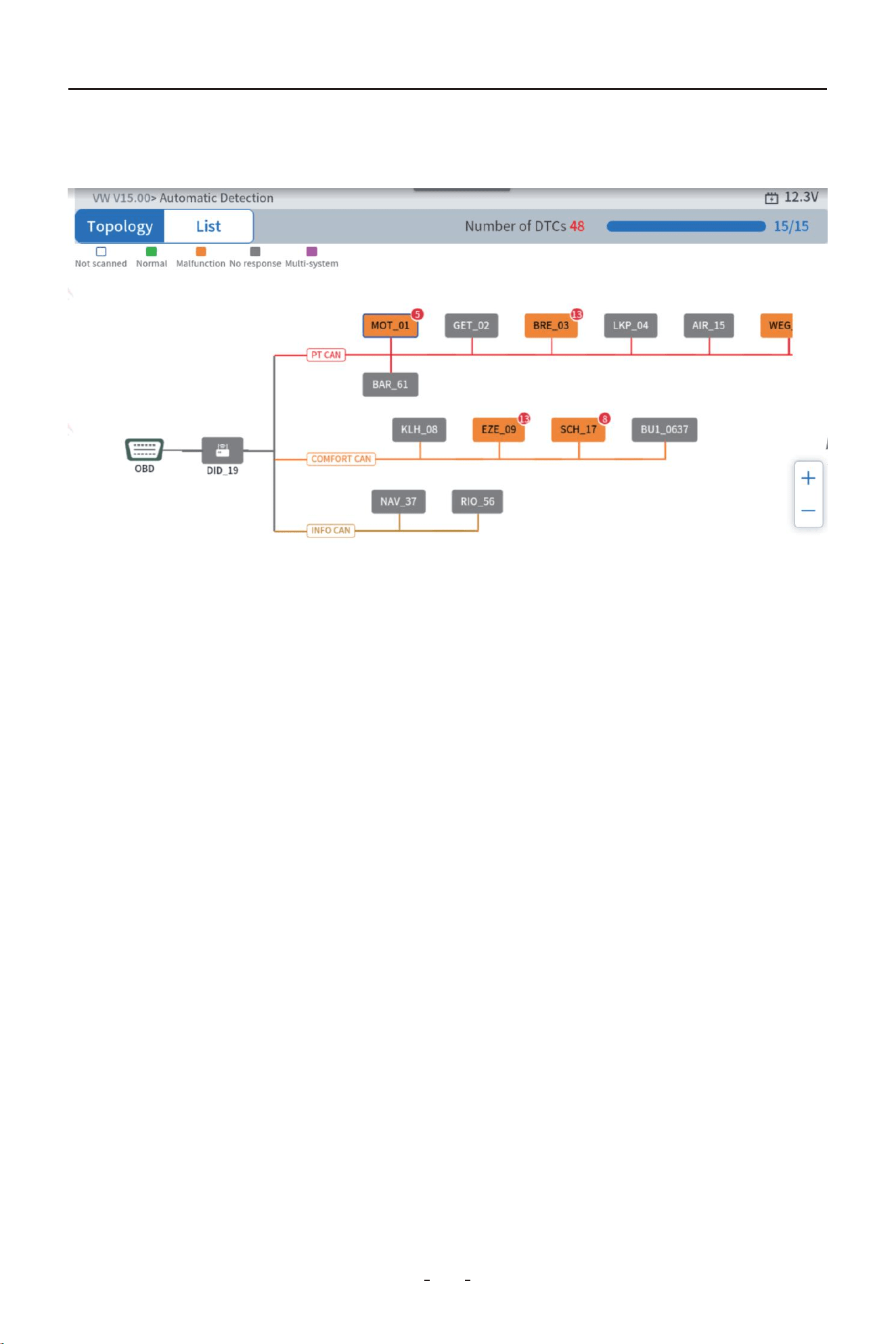
Network Visualization: It provides an oveiew of how ECUs are linked, showing the interr-
elationships between components and the network’s structure.
Ecient Diagnostics: Technicians can easily identify which components are communicating
and whether there are any errors or faults in communication, helping to pinpoint issues
quickly.
Communication Analysis: By visually representing communication paths, it highlights which
modules may not be responding or are malfunctioning, allowing for quicker troubleshooting
and resolution.
Improved Problem-Solving: With topology mapping, technicians can understand the root
Key Benets of Topology Mapping:
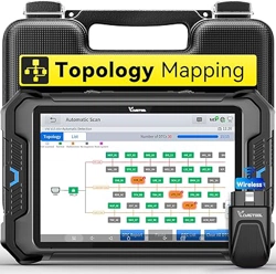
3.11 Topology Mapping
3.10 FCA AutoAuth - SGW
Security Gateway Module (SGW) - In 2018, the SGW was implemented by FCA USA to
prevent unauthorized access. FCA said that SGW was developed to limit "the ability of
non-registered and non-authenticated users to peorm intrusive diagnostics such as
bi-directional controls", so users cannot directly clear the DTC, as well as any bi-direction-
al control test (including actuation, relearn and calibration) on vehicles equipped with
SGW.
VDIAGTOOL Receives Ceication by FCA to access SGW Module, and peorm previously
restricted actions, by registering with AutoAuth, an authentication seice. VDIAGTOOL
Tablet scanner users can register through AutoAuth’s Internet-based registration poal
for $50 a year. (Note: This fee is NOT charged by VDIAGTOOL company)
You can now access the SGW module and peorm operations that were previously
restricted by registering with the AutoAuth authentication seice. This process eliminates
the need for additional accessories. Users begin by registering through AutoAuth's
web-based poal, selecting their desired package, and adding their VDIAGTOOL diag-
nostic tool.
The information above indicates that if you cannot nd "Transmission" or a similar name in
the diagnostic menu, you should locate "Transmission Oil Temperature" under the PID
data (live data) menu of the Powerain Control Module (or PCM). Similarly, if you are
looking for the ABS Bleeding feature, you should go to the Special Function under the
Brake Control Module (BCM). This approach helps navigate and locate specic diagnostic
features within the Diagnostic Tool's inteace.
Topology Mapping is a poweul feature that visually represents the communication net-
work between various electronic control units (ECUs) in a vehicle. This graphical tool helps
technicians and engineers understand how dierent ECUs interact through various data
buses. It’s especially helpful in modern vehicles with complex systems, as it allows users to
see the interconnected structure of ECUs and their communication channels in real-time.
Key Benets of Topology Mapping:
VD80 BT Diagnostic Tool
20
causes of issues more clearly and tackle them with greater eciency, whether it's due to
faulty connections or a module failure.
3.12 Pre/Post Scan
Pre-Scan: Pre-scan is peormed before vehicle maintenance. It scans all fault codes
stored in the vehicle system module, including fault codes without illuminated fault lights,
and generates a diagnostic repo to conrm the fault point.
Post-Scan: Post-scan is peormed after vehicle maintenance. It identies and clears the
fault codes detected during the pre-scan, generates a post-maintenance repo, and
conrms the maintenance costs and other matters to avoid disputes.
VD80 BT Diagnostic Tool
“My vehicles” function allows you to add the diagnostic programs you use often to save
time navigating the vehicles. Click Manual Diagnosis icon on the diagnostic screen, you will
see “My vehicles” listed in the top taskbar.
To add diagnostic program that you use often into this section, click the add icon→select
the region where the vehicle brand is originated→select the brands you often use→click
vehicles” list, click the pen icon- select the diagnostic program you want to remove- click
4.1 My Vehicles
elec-
This chapter describes the basic operation of the Diagnostic Tool function.
The Diagnosis icon is located on the Home screen.
The Diagnostic Tool function allows your Diagnostic Tool to communicate with the
tronic control systems of a vehicle. This allows you to retrieve diagnostic trouble codes
-
ings, adaptations, initializations and etc.
4. How to Diagnose Vehicles
21
VD80 BT Diagnostic Tool
tests and vast number of vehicle makes and models in the United States, Europe, Asia, Aus-
-
4.1.1 Compatibility Check
To check compatibility, please consult tech suppo via suppo@vdiagtool.com any time or refer
to our website https://www.vdiagtool.com/suppo/vehicle-coverage (for reference only,
IMPORTANT:
Special Functions on the main diagnostic screen are not universally available to all vehicles.
with the vehicle VIN, make, model and year.
subject to conrmation from tech suppo)
20
VD80 BT Diagnostic Tool
This Diagnostic Tool displays the current software program version at the bottom of each
vehicle manufacturer. For example, the current installed Benz software program is V21.80 as
shown in picture below.
4.2 Software Program Version
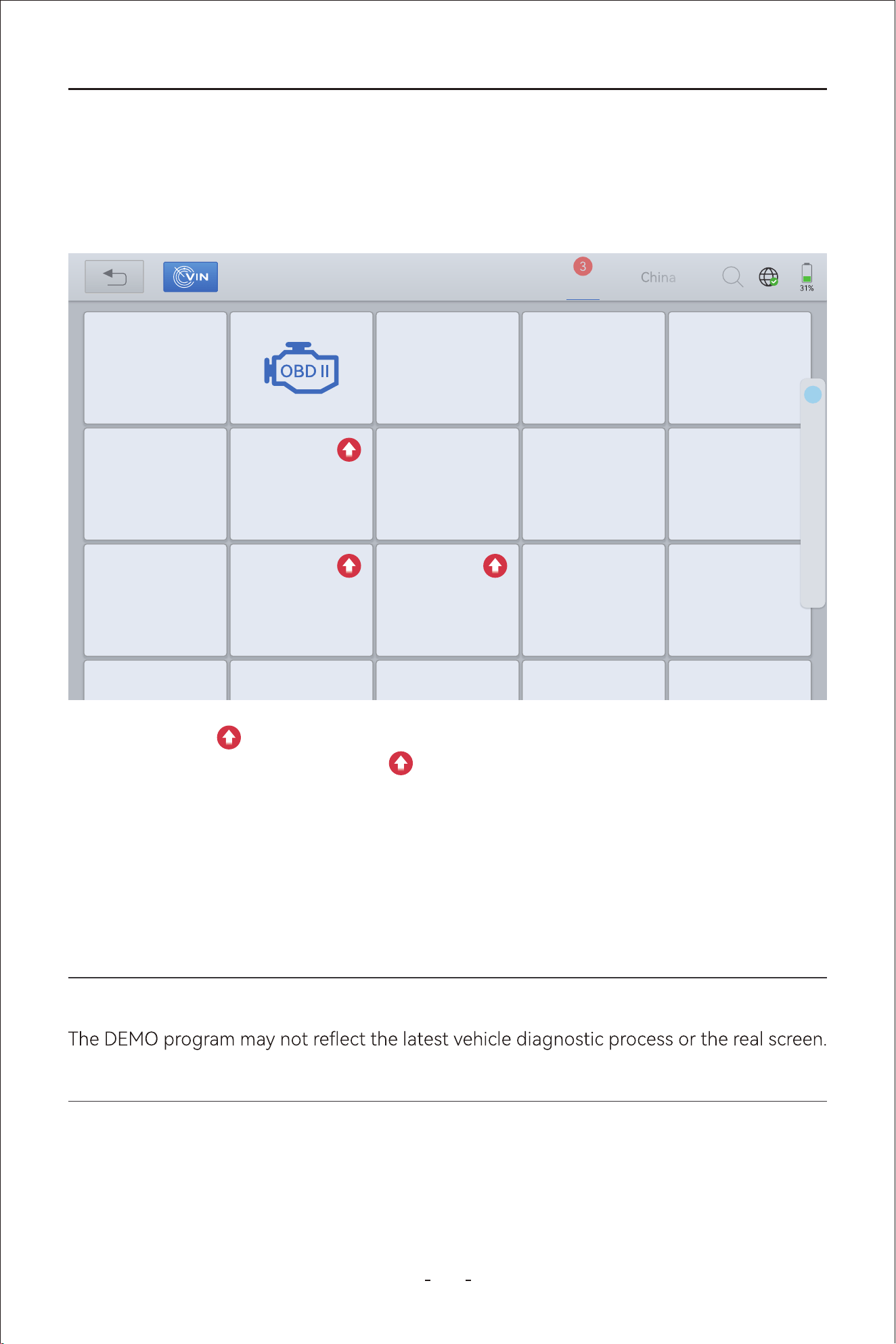
The “DEMO” program simulates the vehicle navigation process, the functions options avail-
able and what the menu looks like. You may use this DEMO program to practice how to use
the Diagnostic Tool function before you activate the tool.
4.3 Demo Program
IMPORTANT:
This program are NOT used for vehicle coverage/compatibility check.
The red up arrow indicates there is a newer version software program available for dow-
nload. And when you have clicked the arrow to update the software program and insta-
lled it, the Diagnostic Tool will display a newer version software program installed.
My vehicles Europe America Asia
Diagnosis for
V6.30
DEMO
Diagnosis for
V12.40
ACURA
Diagnosis for
V5.35
DAEWOO
Diagnosis for
V8.41
DAIHATSU
Diagnosis for
V12.40
HONDA
Diagnosis for
V14.10
HYUNDAI
Diagnosis for
V5.18
HYUNDAICV
Diagnosis for
V13.80
INFINITI
Diagnosis for
V9.20
ISUZU
Diagnosis for
V14.10
KIA
Diagnosis for
V14.80
LEXUS
Diagnosis for
V13.70
MAZDA
Diagnosis for
V12.20
MITSSUBISSH
I
Diagnosis for
V13.81
NISSAN
Diagnosis for Diagnosis for Diagnosis for Diagnosis for Diagnosis for
Diagnosis for
V21.51
D
H
I
K
L
M
N
P
R
S
T
A
22
21
VD80 BT Diagnostic Tool
The Diagnostic Tool comes with a few trials which you can use to check the functions of the
Diagnostic Tool or compatibility with your vehicle before you actually activates the tool.
inspections and random inspections) it went through.
4.4 Trial Mode
This Diagnostic Tool can connect to 2.4 GHz or 5.0 GHz frequency hotspot or Wi-Fi. Swipe
up the hidden bottom toolbar and see the tab menu. Click Home- Network & internet-
Switch on Wi-Fi connection-Click Wi-Fi icon to view Wi-Fi available-Select the Wi-Fi you
want to connect and input password to connect.
-
nection, you can connect to your mobile phone hot spot.
For iOS users, go to Settings- Personal Hotspot- Switch on “Allow Others to Join” and
“Maximize Compatibility” to set your phone and connect to the hotspot from your Diagnos-
tic Tool following the steps above.
For Android phone users, go to
-
tion Type- WPA2 PSK- Show advanced options and make sure “Max connections allowed”
has user left for the Diagnostic Tool.
4.5 Wi-Fi Connection
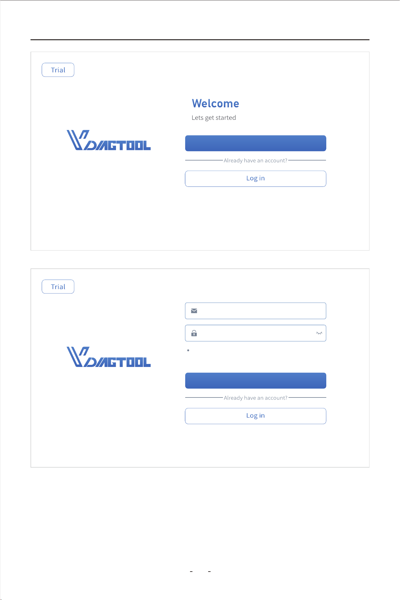
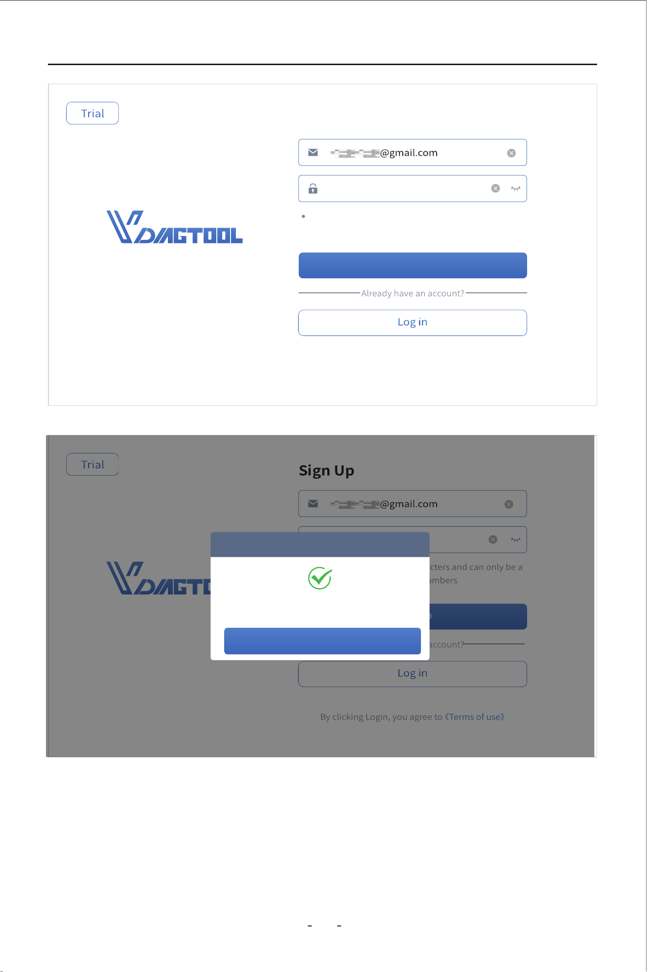
When the Diagnostic Tool ran out of trials, you have to register and activate the Diagnostic
Tool to continue using the diagnostic programs.
To register the Diagnostic Tool, click “Register”- input your email address- set the password
and repeat the password- agree to the User Terms and submit your registration. When you
see registration completed on the screen, the Diagnostic Tool has been registered and acti-
vated! And you can use the email address and password you just set for login(the Diagnos-
tic Tool will remember your account information once registered and you don’t need to
4.6 Product Activation
Note:
Wi-Fi connection is not required in diagnostics for most of the vehicle brands. Diagnostics
-
nect to Wi-Fi while diagnosing.
23
22
VD80 BT Diagnostic Tool
Sign Up
Email address
Password
Password must be 8-20 characters and can only be a
combination of letters and numbers
Sign Up
Sign Up
By clicking Login, you agree to 《Terms of use》
24
23
VD80 BT Diagnostic Tool
··········
Password must be 8-20 characters and can only be a
combination of letters and numbers
Sign Up
Sign Up
By clicking Login, you agree to 《Terms of use》
··········
Password must be 8-20 characters and can only be a
combination of letters and numbers
Sign Up
Sign Up
By clicking Login, you agree to 《Terms of use》
Login successful
Prompt
OK
25

PauseData recording
VD70S Diagnostic Tool
24
VD80 BT Diagnostic Tool
Note:
If you are unable to register the Diagnostic Tool or you can’t see the activation screen, con-
website www.vdiagtool.com asap for assistance.
Sta now
Congratulations!
S/N VD80 BT-1234567 has been successfully activated
Subscription expiration date: Remaining subscription: 1096 Days
(2025-2-24-2027-2-24)
For more information and seices, please visit ocial website: www.vdiagtool.cpm
PauseRecordExit
CombineCustom Data recordingCancel Selected
8/8
0.0s
14.50
7.052s 14.104s 21.156s 28.208s 35.26s 43.312s 49.364s
56.416s
63.468s 70.52s
28.40
28.40
1.3327
X : 22.75 (s)
Y : 34.9 | %
0.0s
14.50
7.052s 14.104s 21.156s 28.208s 35.26s 43.312s 49.364s
56.416s
63.468s 70.52s
28.40
28.40
0.4428
26
27
VD80 BT Diagnostic Tool
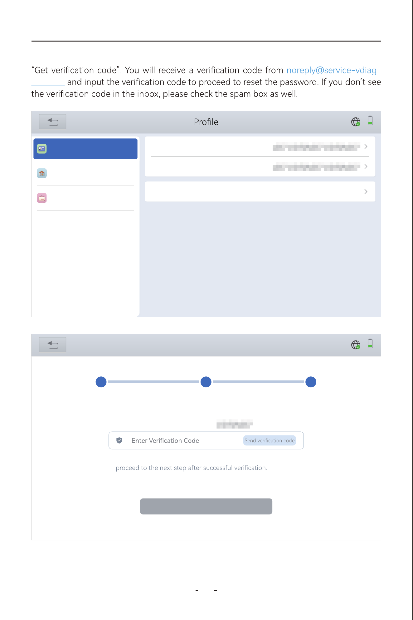
If you forget your password, click “New password” and input your email address and click
-
tool.com
31%
Subscription
Username
Mailbox
Workshop
Account Information
New password
Log out
31%
New password
1
Authentication
2
New password
3
Completed
Verify with current e-mail 123456789@qq.com
For the security of your account, please verify your identity and
Verify
Data recording
28
VD80 BT Diagnostic Tool
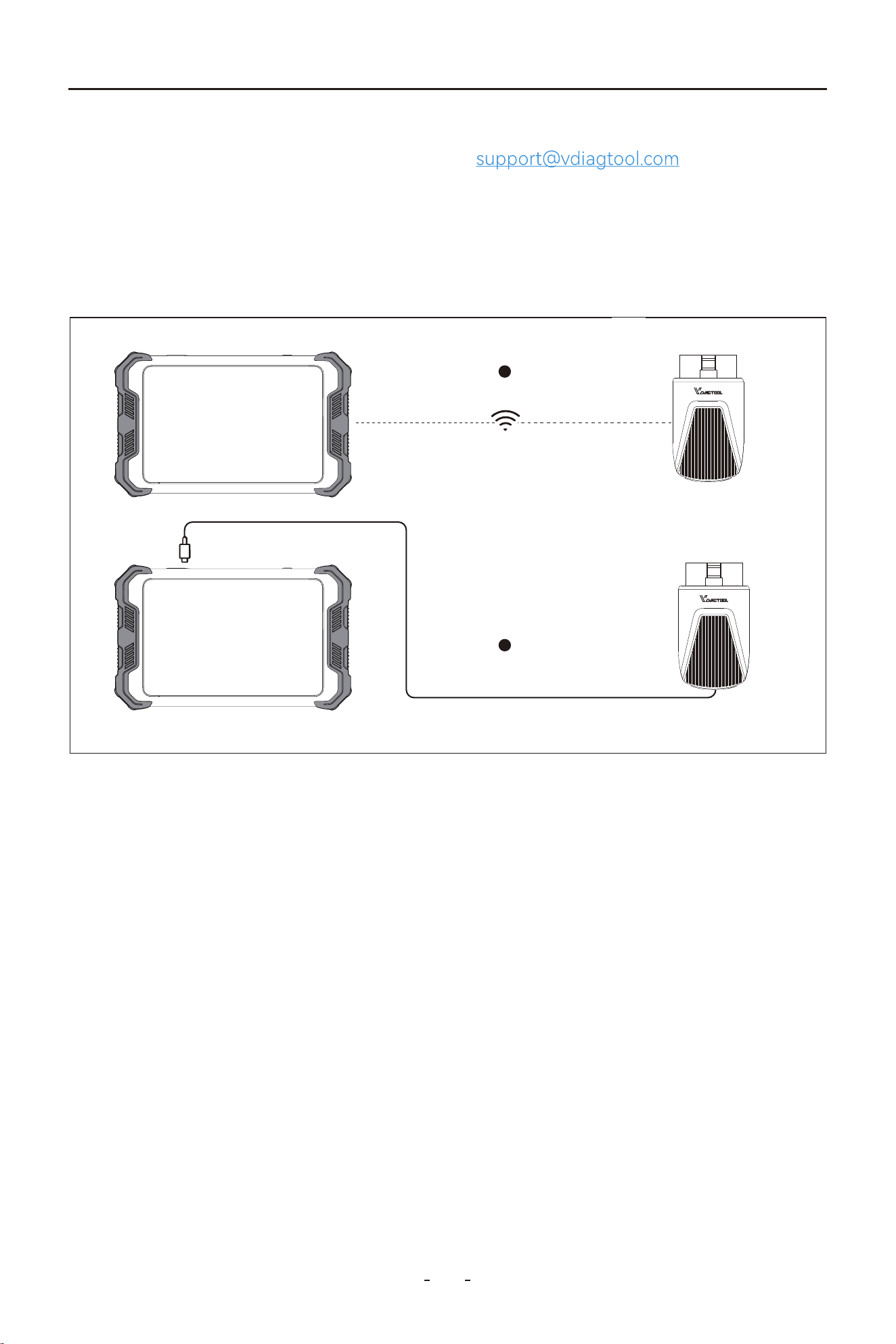
Step 1: Turn on the Diagnostic Tool.
Step 3: Turn on the ignition and run the diagnostic program on the Diagnostic Tool.
Step 2:
Plug VCI box into vehicle’s OBDII po, make sure Power and Wi-Fi indicators light
4.8 Diagnose Vehicles
To establish communication between the Diagnostic Tool and the vehicle, please follow the
steps below:
icle.
The vehicle must be correctly identied for the Diagnostic Tool to communicate and peorm
enter the information. Exact procedures may va by the make, model, and year of the veh-
diagnostics. The vehicle identication sequence is menu driven, follow the screen prompts to
To identify a vehicle for diagnostics, you have 4(four) options listed as below:
If you forgot the email address you used for the product activation, please send the S/N
(Serial Number) of the Diagnostic Tool to
to recover the
registration information.
The Diagnostic Tool uses a VCI box that has OBDII-16 male connector for vehicle commu
nication.
Note: The VCI box connects to the Diagnostic Tool via WiFi. If the WiFi function is not wor-
king currently, you can also connect to the Diagnostic Tool directly via a Type-C cable.
-
4.7 Connecting the VCI Box
2
1
2

29
VD80 BT Diagnostic Tool
4.8.1 Auto Scan
Click “Auto Scan” icon on the diagnostic screen, and the Diagnostic Tool will scan the vehi-
cle VIN and decode the VIN for vehicle identication automatically.
4.8.2 Manual Diagnosis
Click “Manual Diagnosis” icon on the diagnostic screen, the Diagnostic Tool will bring up
vehicle selection menu. Click the icon at the top left corner, and you will see “Auto
Scan” and “Manual Input” icons available. Click “Manual Input” to input the vehicle VIN
number(17 digits) manually and the Diagnostic Tool will decode the VIN number and iden-
tify the vehicle.
4.8.3 Automatic Detection
Click “Manual Diagnosis”- Select region where the vehicle brand is originated, for example
“Americas”- Select the vehicle brand, for example “CADILLAC”- Select “Automatic Detec-
tion” to automatically detect and identify the vehicle the Diagnostic Tool is connected to.
IMPORTANT:
It’s a common misconception that the Diagnostic Tool can not communicate with a vehicle
for diagnostics if it can not detect and/or decode the VIN number. T other vehicle identi-
cation options instead when Auto Scan fails. Use “Manual Selection” as your nal but reli-
able solution.
Note:
Auto Scan does NOT work on all vehicles. When Auto Scan fails, t other options instead.
Note:
Some vehicle VIN numbers cannot be decoded. When Auto Scan and Manual Input fails, t
Automatic Detection or Manual Selection instead.
Note:
Automatic Detection does not work on all vehicle models. Select Manual Selection instead
if the above all three options above failed.
30
VD80 BT Diagnostic Tool
4.8.5 Manual Selection
When the “Auto Scan”, “Manual Input” and “Automatic Detection” fails to identify the vehi-
cle, you can always select “Manual Selection” to identify the vehicle and proceed to diag-
4.8.6 Automatic Scan
It is to scan all available vehicle modules for diagnostics.
To identify a vehicle through “Manual Selection”, click “Manual Diagnosis”- Select region
where the vehicle brand is originated, for example “Americas”- Select the vehicle brand, for
example “CADILLAC”- Select “Manual Selection”- Select the model year- Model Name-
and you may go through a few other selections before you see “Automatic Scan” and
“System Selection” on the screen.
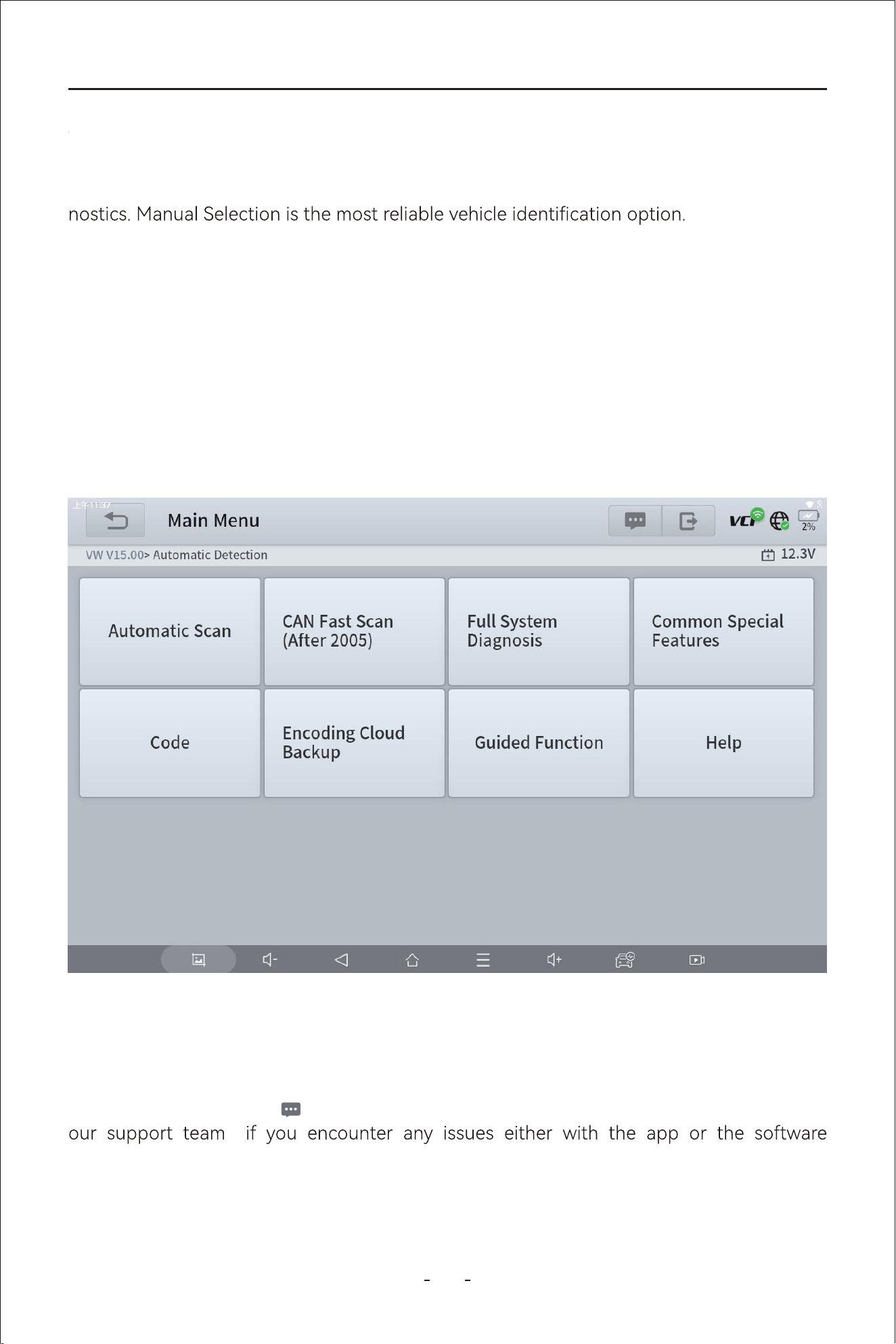
4.9 Submit Feedback
When you have done automatic scan, the Diagnostic Tool will display fault impacted vehicle
systems and failure number in orange and on top.
31%
Main menu
VW V14.30> Automatic Detection
Automatic Scan
CAN fast scan
(after 2005)
Help
Full system
diagnosis
Common special
features
Click the message icon on the top right corner will allow you to submit feedback to
programs.
4.8.4 Manual Selection
4.8.5 Automatic Scan
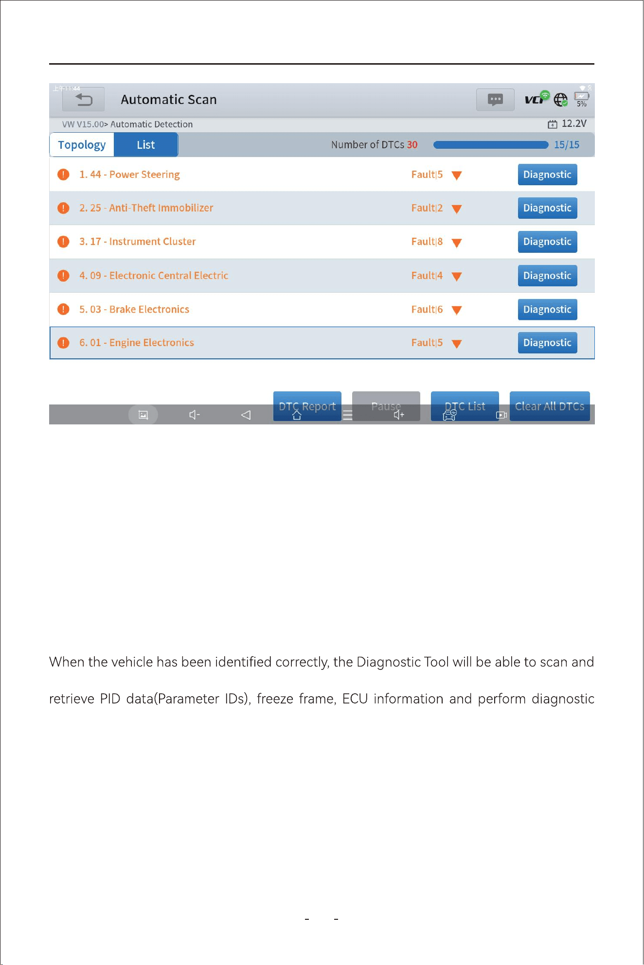
31
VD80 BT Diagnostic Tool
4.12.1 Read Codes
Displays diagnostic trouble code (DTC) records from the vehicle electronic control module.
Selecting may open a sub-menu of viewing options.
4.12 Diagnostics
Scan all available vehicle systems for vehicles that use CAN protocol for vehicle communi-
cation post 2005 much faster.
4.10 CAN Fast Scan
It’s for you to pick an individual vehicle module for diagnostics when you have in mind
where the car problems might be.
4.11 System Selection
access the vehicle electronic control systems to pull diagnostic trouble codes(DTCs),
tests like active tests(bi-directional controls) and advanced resets, relearns, matchings,
adaptations and initializations.
In the process of diagnosis, if the Diagnostic Tool shows “System is OK” or “No Trouble
Code”, it either means there is no related fault codes stored in ECU or some faults are not
5.03 - Brake Electronics
Failure | 1
Diagnosis
1
Invalid Data Received From, Instrument Panel Cluster Control Module
Passive/Sporad
ic
U042300
[004197]
2
Invalid Data Received From, Instrument Panel Cluster Control Module
Passive/Sporad
ic
U042300
[0041A3]
3
Invalid Data Received From Body Control Module
Passive/Sporad
ic
U042200
[0041A2]
4.09 - Electronic central electric
Failure | 3
Diagnosis
3.17 - Instrument cluster
Failure | 2
Diagnosis
6.01 - Engine electronics
Failure | 3
Diagnosis
7.15 - Airbag
Diagnosis
Normal | No DTC
Pause Clear All DTCs
31%
Automatic Scan
VW V14.30> Automatic Detection
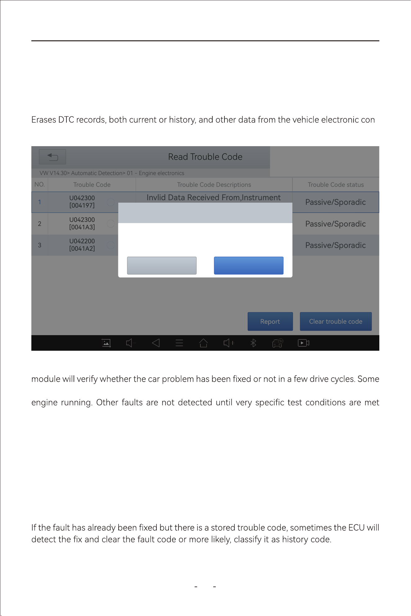
32
VD80 BT Diagnostic Tool
4.12.2 Clear Codes
-
trol module.
4.12.3 DTC Erased While Fault Remains
4.12.4 DTC Erased and Fault Fixed - Histo Code
If the fault codes are erased while the fault remains unresolved, the fault code will reappear
after a few drive cycles.
in that ECU, most faults are mechanical system faults or executive circuit faults. It is also
possible that the signal of a sensor may be inaccurate but within limits, which can be exam-
ined using Live Data (PID data).
When erase command sent through the diagnostic program, the vehicle electronic control
faults are immediately detected by the ECU with the key in the run position and without the
such as engine coolant temperature within a range, speed within a range for a duration of
time, throttle percentage within a range, etc.
31%
Read Trouble Code
VW V14.30> Automatic Detection> 01 - Engine electronics
NO.
Trouble Code Trouble Code Descriptions Trouble Code status
1
U042300
[004197]
Passive/Sporadic
Invlid Data Received From,Instrument
Invlid Data Received From
2
U042300
[0041A3]
Passive/Sporadic
Invlid Data Received From,Instrument
Invlid Data Received From
3
U042200
[0041A2]
Passive/Sporadic
Invlid Data Received From,Instrument
Invlid Data Received From
Clear trouble code
Clear Trouble Code
Do you want to clear all the trouble code(s)?
YesNo
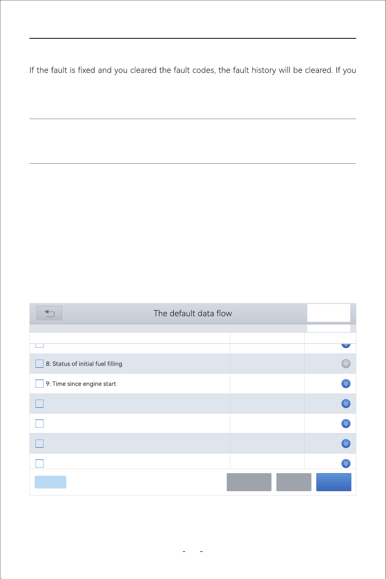
33
VD80 BT Diagnostic Tool
intend to have another technician to investigate the car problem, it is not recommended to
clear the fault code since doing so may erase information helpful to others who may inves-
tigate the problem.
4.12.6 PID Data
Displays PID data for various sensors from the vehicle electronic control module. This Diag-
nostic Tool allows viewing real-time PID data of various sensors in a list, view individual PID
data in graphing, analog dashboard, setting maximum and minimum values, view custom
PID data up to 8 sensors in a list, individual graphing and merged graphing.
4.12.7 PID Data List
Click live data function and the Diagnostic Tool will display a list of PID names and real-time
values on the screen as shown in picture below:
Note:
Clearing codes will erase the freeze frame data.
31%
VW V14.30> Automatic Detection> 01 - Engine electronics> Live data
DEFAULT
0
S
0.0
11: Absolute load value
%
16.9
10: Throttle valve postion (absolute)
%
14.9
13: Accelerator nedal nosition
%
0.0
12: Normed load value
%
12.480
7: Voltage terminal 30
V
Name Value Unit
PauseCustomCancel Selected
0/236
4.12.5 DTC Erased and Fault Fixed - Histo Cleared
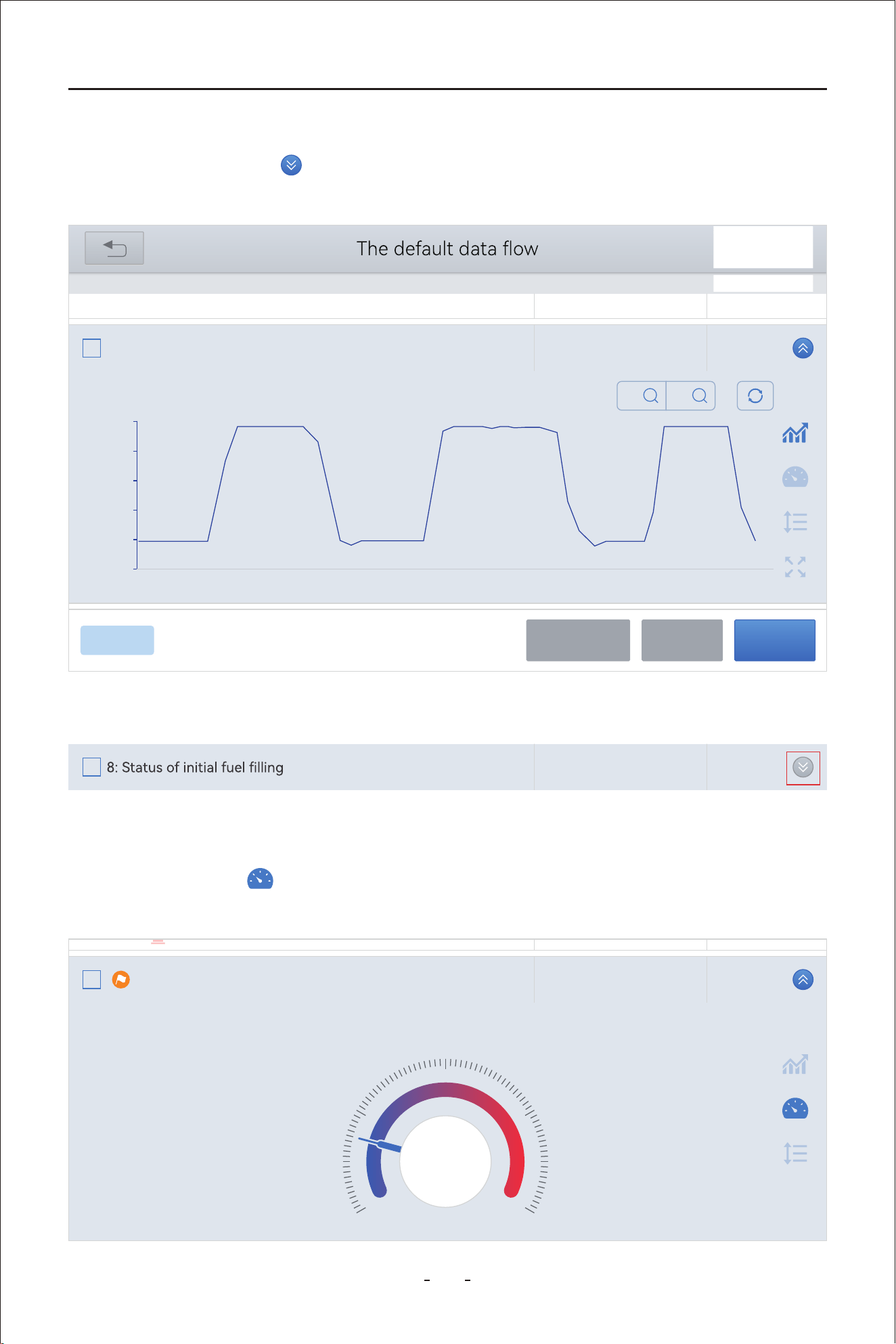
34
VD80 BT Diagnostic Tool
4.12.8 Individual PID Data Graphing
Click the meter icon and the Diagnostic Tool will show the PID value in analog dash-
board as shown in picture below:
If the blue arrow is gray, it means this PID data is not available to be shown in graphing.
Click the blue arrow icon on the right to view graphing for individual PID data as shown
in picture below:
4.12.9 Individual PID Data in Analog Dashboard
31%
VW V14.30> Automatic Detection> 01 - Engine electronics> Live data
17.3
10: Throttle valve posotopn (absolute)
%
Name Value Unit
PauseCustomCancel Selected
0/236
0.00
0009 0010 0011 0012 0013 0014 0015 0016 0017 0018 0019
18.00
36.00
54.00
72.00
90.00
Min: 14.5 Max: 86.7
X
X1
Y
X1
DEFAULT
16.9
10: Throttle valve posotopn (absolute)
%
Name Value Unit
Min: 14.5 Max: 86.7
45.0
0.0 90.0
22.5 67.5
16.9
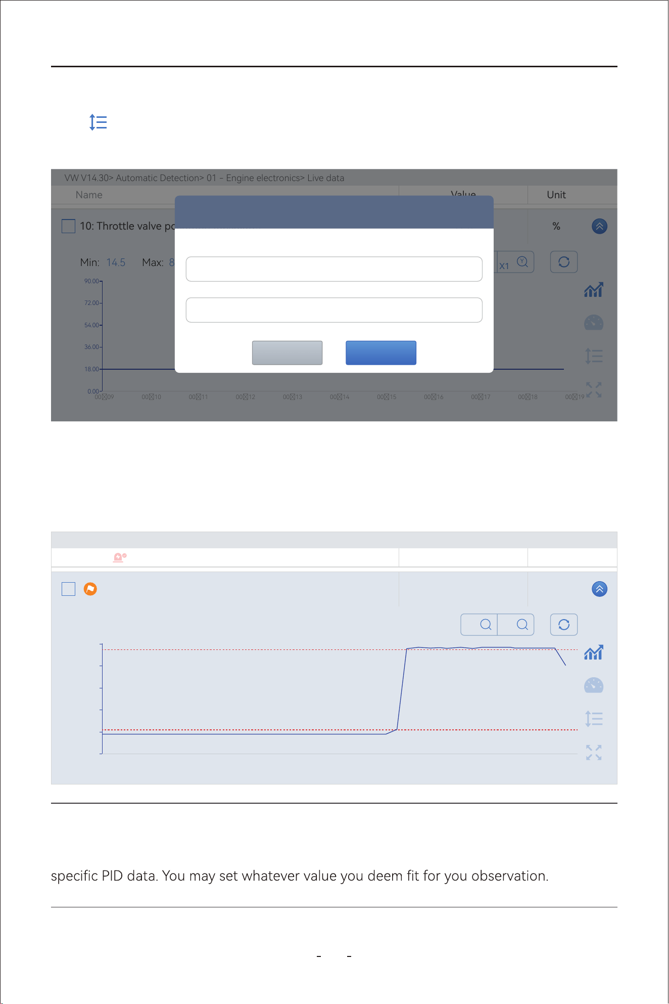
35
VD80 BT Diagnostic Tool
Note:
The maximum and minimum values do not have to be within the normal value range for the
Once the maximum and minimum values are set on the screen, the Diagnostic Tool will
show two dotted red lines on the screen so that you can easily spot whether the PID data
rises over the maximum value or drops below the minimum value you just set as shown in
picture below:
Click icon on the right to set maximum and minimum value alarms for individual PID
data as shown in picture below:
VW V14.30> Automatic Detection> 01 - Engine electronics> Live data
17.3
10: Throttle valve posotopn (absolute)
%
Name Value Unit
0.00
0009 0010 0011 0012 0013 0014 0015 0016 0017 0018 0019
18.00
36.00
54.00
72.00
90.00
Min: 14.5 Max: 86.7
X
X1
Y
X1
Prompt
Please enter the minimum value
Please enter the minimum value
OKCANCEL
VW V14.30> Automatic Detection> 01 - Engine electronics> Live data
72.2
10: Throttle valve posotopn (absolute)
%
Name Value Unit
Min: 14.5 Max: 86.7
0.00
0110 0111 0112 0113 0114 0115 0116 0117 0118 0119 0120
18.00
36.00
54.00
72.00
90.00
X
X1
Y
X1
4.12.10 Set Maximum & Minimum Value Alarms
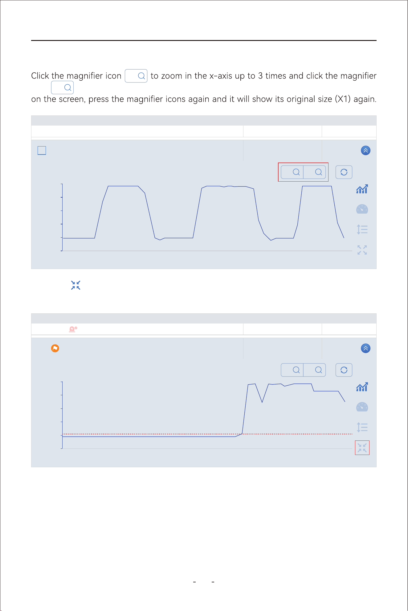
36
VD80 BT Diagnostic Tool
4.12.12 Custom Up to 8 PID Data
This Diagnostic Tool allows you to tick the boxes for up to 8(eight) PID data and click
“Custom” to show custom list of real-time PID data.
Click the icon on the right will allow you to view the individual graphing in full screen
as shown in picture below:
icon to zoom in the y-axis up to 3 times. When it shows 3 times for x-axis or y-axis
X
X1
Y
X1
VW V14.30> Automatic Detection> 01 - Engine electronics> Live data
17.3
10: Throttle valve posotopn (absolute)
%
Name Value Unit
0.00
0009 0010 0011 0012 0013 0014 0015 0016 0017 0018 0019
18.00
36.00
54.00
72.00
90.00
Min: 14.5 Max: 86.7
X
X1
Y
X1
VW V14.30> Automatic Detection> 01 - Engine electronics> Live data
42.0
10: Throttle valve posotopn (absolute)
%
Name Value Unit
Min: 14.5 Max: 86.7
0.00
0006 0007 0008 0009 0010 0011 0011 0012 0013 0014 0015
900
1800
2700
3600
45.00
X
X1
Y
X1
4.12.11 Zoom In & Zoom Out & View In Full Screen
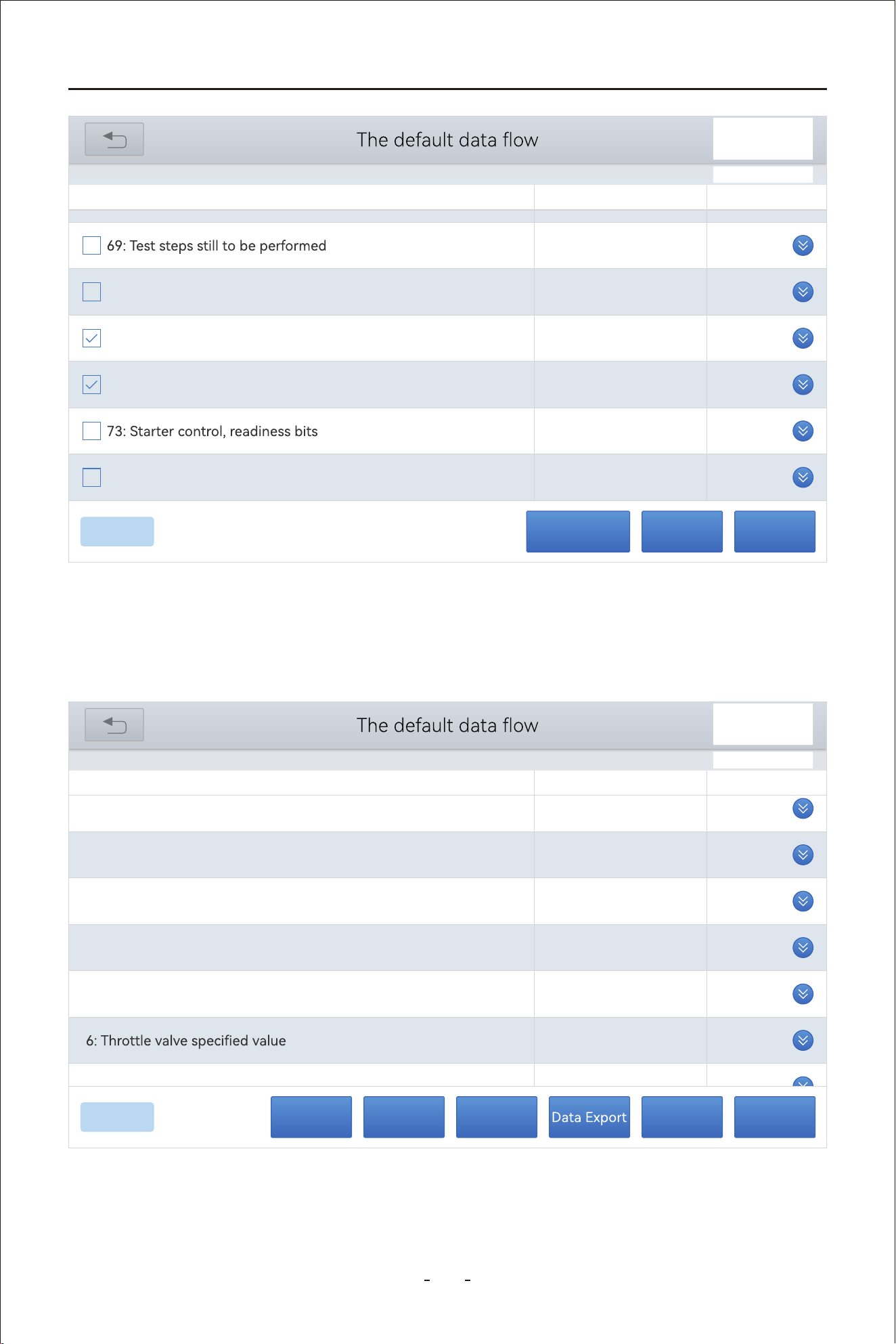
37
VD80 BT Diagnostic Tool
Cancel Selected - To cancel the PID data you selected so that you can re-select them.
Custom - Proceed to display the custom screen for the PID data you selected.
Pause - To pause the continuous retrieving process for the real-time PID data.
PauseCustomCancel Selected
8/236
0
70: Cause for cancellation
0.8548
71: Throttle valve position 1
V
0
16.9
72: Throttle valve position 2
%
1
0
74: Result test Evap. Emission (EVAP) Canister Purge Reg. Valve
VW V14.30> Automatic Detection> 01 - Engine electronics> Live data
Name Value Unit
31%
14.9
1: Throttle valve position (absolute)
%
16.5
2: Acceleratir pedal position
%
3.9
3: Throttle valve position, normed
%
0.7550
4: Accelerator pedal, sensor voltage 1
V
0.3793
5: Accelerator pedal, sensor voltage 2
V
3.9
%
0.7413
7: Throttle valve nosition 1
V
Name Value Unit
PauseRecordCombineGraphDisplay All
8/8
31%
VW V14.30> Automatic Detection> 01 - Engine electronics> Live data
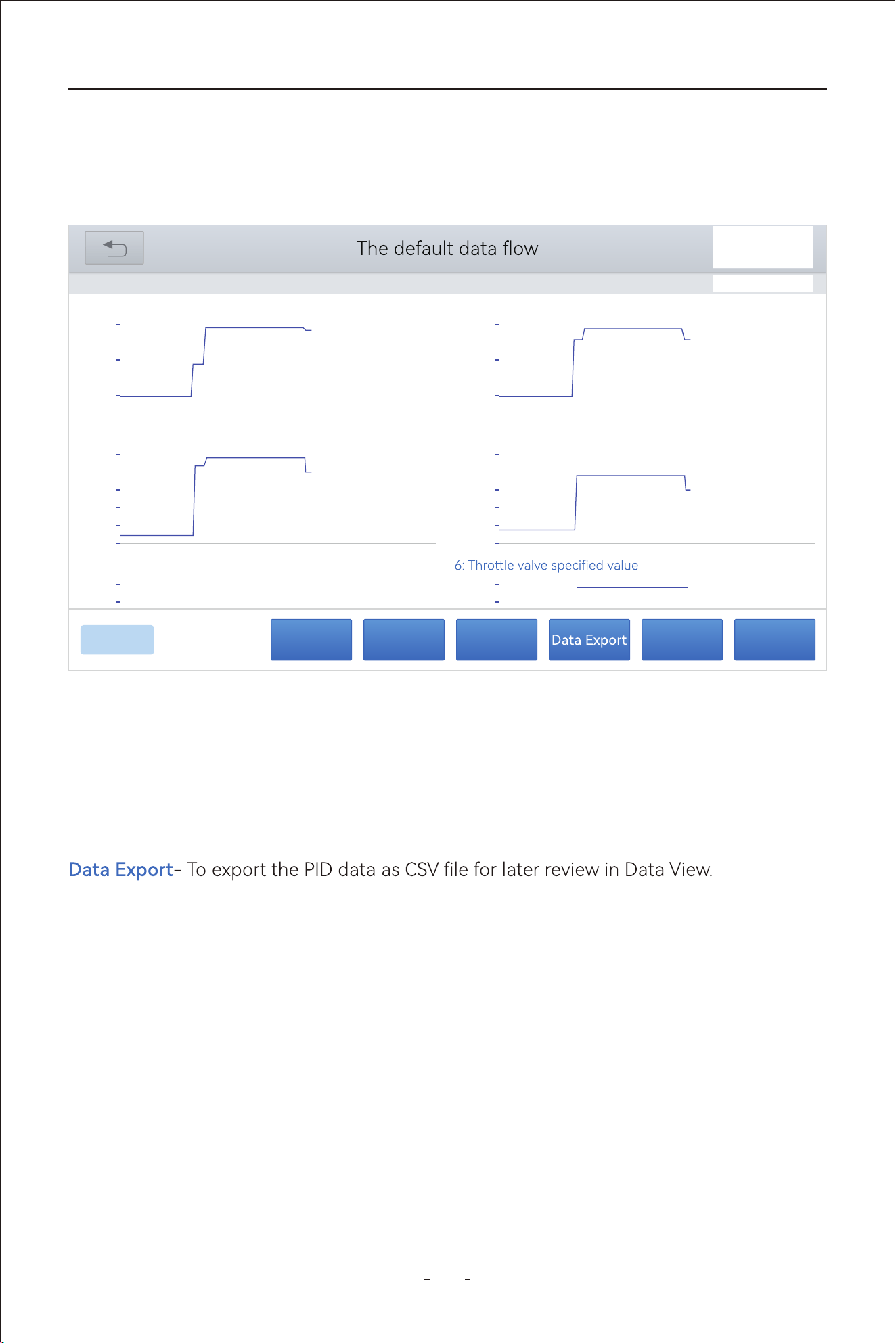
38
VD80 BT Diagnostic Tool
4.12.13 Individual Graphing for Up to 8 PID Data
Click the “Graph” icon on the custom PID data list screen, and the Diagnostic Tool will show
individual graphs for up to 8 PID data on one single screen, as shown in picture below:
Display All- To exist the custom PID data screen and display all PID data list with the
previous selected PID data boxes still ticked.
Graph- To show the selected PID data in graphing.
List- To show the selected PID graphing in data list.
Combine- To combine the individual graphing into merged graphing.
Record- To record the PID data for later review in Data Playback.
Pause- To pause the continuous retrieving process for the real-time PID data.
4.12.14 8-In-1 Graphing
Click the “Combine” icon will merge the individual graphs into one merged graphing screen.
This Diagnostic Tool is capable of graphing up to 8 (eight) PID data on one single screen to
view and compare related PID data. Tick the box at the left side for up to 8 (eight) sensor
data, then click “Combine” to merge the 8(eight) graphs on one single screen.
PauseRecordCombineListDisplay All
8/8
31%
VW V14.30> Automatic Detection> 01 - Engine electronics> Live data
00:00
0.00
00:01 00:02 00:03 00:04 00:05 00:06 00:07 00:08 00:09 00:10
18.00
36.00
54.00
72.00
90.00
1:Throttle valve position (absolute) 83.5 %
00:00
0.00
00:01 00:02 00:03 00:04 00:05 00:06 00:07 00:08 00:09 00:10
16.00
32.00
48.00
64.00
80.00
2:Accelerator pedal position 65.9 %
00:00
0.00
00:01 00:02 00:03 00:04 00:05 00:06 00:07 00:08 00:09 00:10
14.00
28.00
42.00
56.00
70.00
3: Throttle valve position, normed 55.7 %
00:00
0.00
00:01 00:02 00:03 00:04 00:05 00:06 00:07 00:08 00:09 00:10
1.00
2.00
3.00
4.00
5.00
4: Accelerator pedal, sensor voltage 1 3.0447 V
4.00
5.00
5: Accelerator pedal, sensor voltage 2 1.4850 V
56.00
70.00
41.2 %
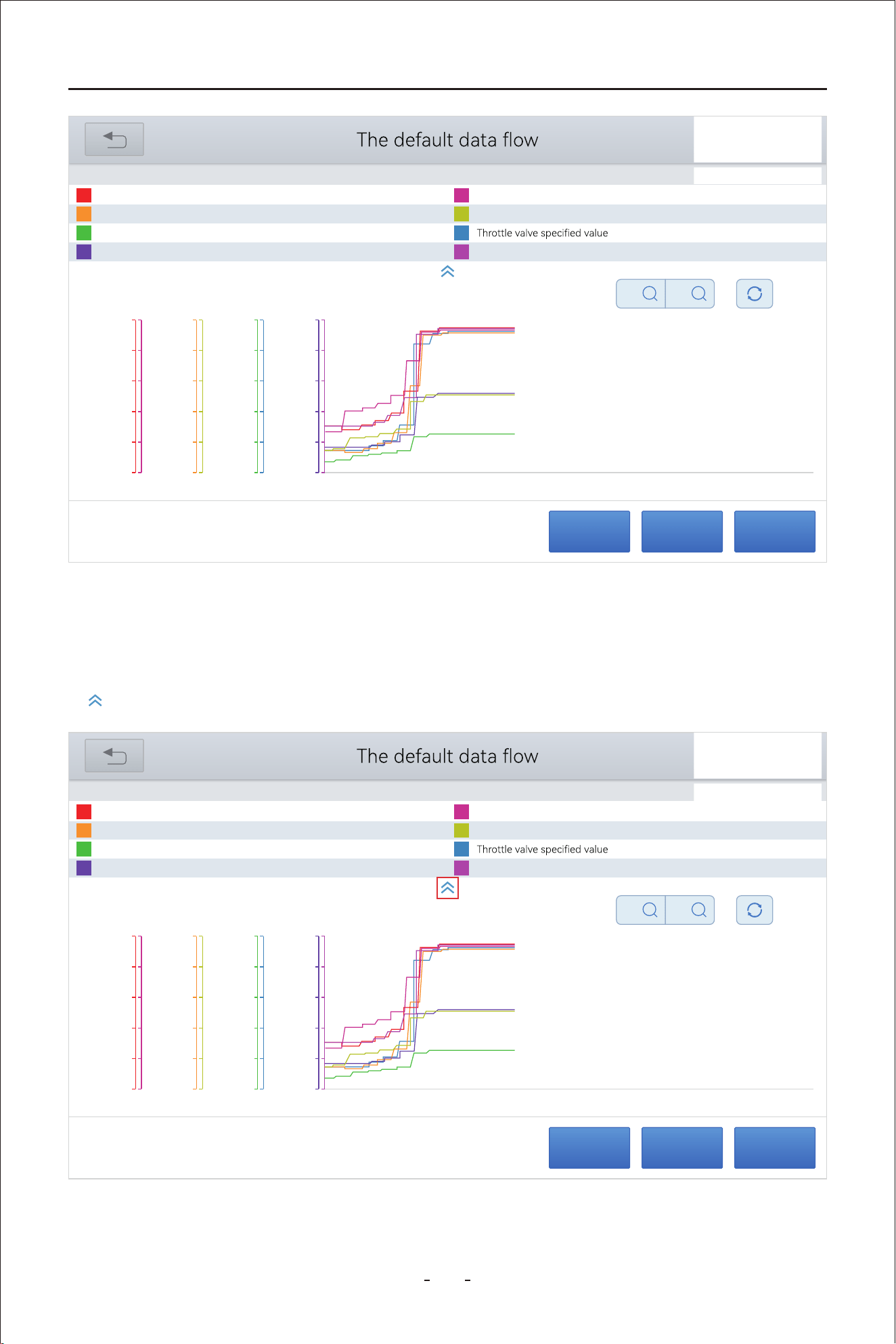
39
VD80 BT Diagnostic Tool
4.12.15 Fold & Unfold PID Data Name
PauseRecordExit
31%
VW V14.30> Automatic Detection> 01 - Engine electronics> Live data
Throttle valve position (absolute)
52.2
%
Accelerator pedal position
51.0
%
Throttle valve position, normed
36.5
%
Accelerator pedal, sensor voltage 1
2.5494
V
Accelerator pedal, sensor voltage2
1.2778
V
36.9
%
Throttle valve position 1
2.5998
V
Throttle valve position 2
51.8
%
X
X1
Y
X1
80.00
64.00
48.00
32.00
16.00
0.00
90.00
72.00
54.00
36.00
18.00
0.00
5.00
4.00
3.00
2.00
1.00
0.00
70.00
56.00
42.00
28.00
14.00
0.00
70.00
56.00
42.00
28.00
14.00
0.00
5.00
4.00
3.00
2.00
1.00
0.00
90.00
72.00
54.00
36.00
18.00
0.00
5.00
4.00
3.00
2.00
1.00
0.00
00:00 00:01 00:02 00:03 00:04 00:05 00:06 00:07 00:08 00:09 00:10
This Diagnostic Tool allows you to fold the PID data name list so that you can view the
merged graphs in a bigger screen. To fold the PID data name list, click the up arrow icon
as shown below:
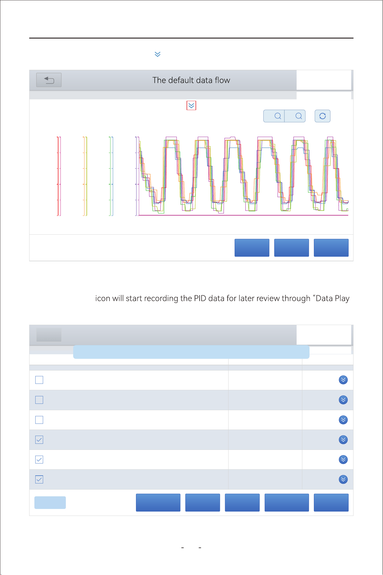
40
VD80 BT Diagnostic Tool
To unfold it, click the down arrow icon if you want to check the names of the PID data.
4.12.16 Data Recording & Playback
Click the “Record”
-
back” function.
PauseCombineCustom Data recordingCancel Selected
8/8
40356
Total distance (absolute value)
km
840
Revolution counter
1/min
23.00
Fuel level sensor, right
l
44.00
Total fuel level of both fuel level sensors (sum value)
l
21.00
Fuel level sensor, left
l
50.00
Outside temperature sensor
deg C
DEMO V5.60> A
Name Value Unit
General
Data recording is turned on, press again to end data recording
PauseRecordExit
31%
VW V14.30> Automatic Detection> 01 - Engine electronics> Live data
X
X1
Y
X1
80.00
64.00
48.00
32.00
16.00
0.00
90.00
72.00
54.00
36.00
18.00
0.00
5.00
4.00
3.00
2.00
1.00
0.00
70.00
56.00
42.00
28.00
14.00
0.00
70.00
56.00
42.00
28.00
14.00
0.00
5.00
4.00
3.00
2.00
1.00
0.00
90.00
72.00
54.00
36.00
18.00
0.00
5.00
4.00
3.00
2.00
1.00
0.00
00:00 00:01 00:02 00:03 00:04 00:05 00:06 00:07 00:08 00:09 00:10
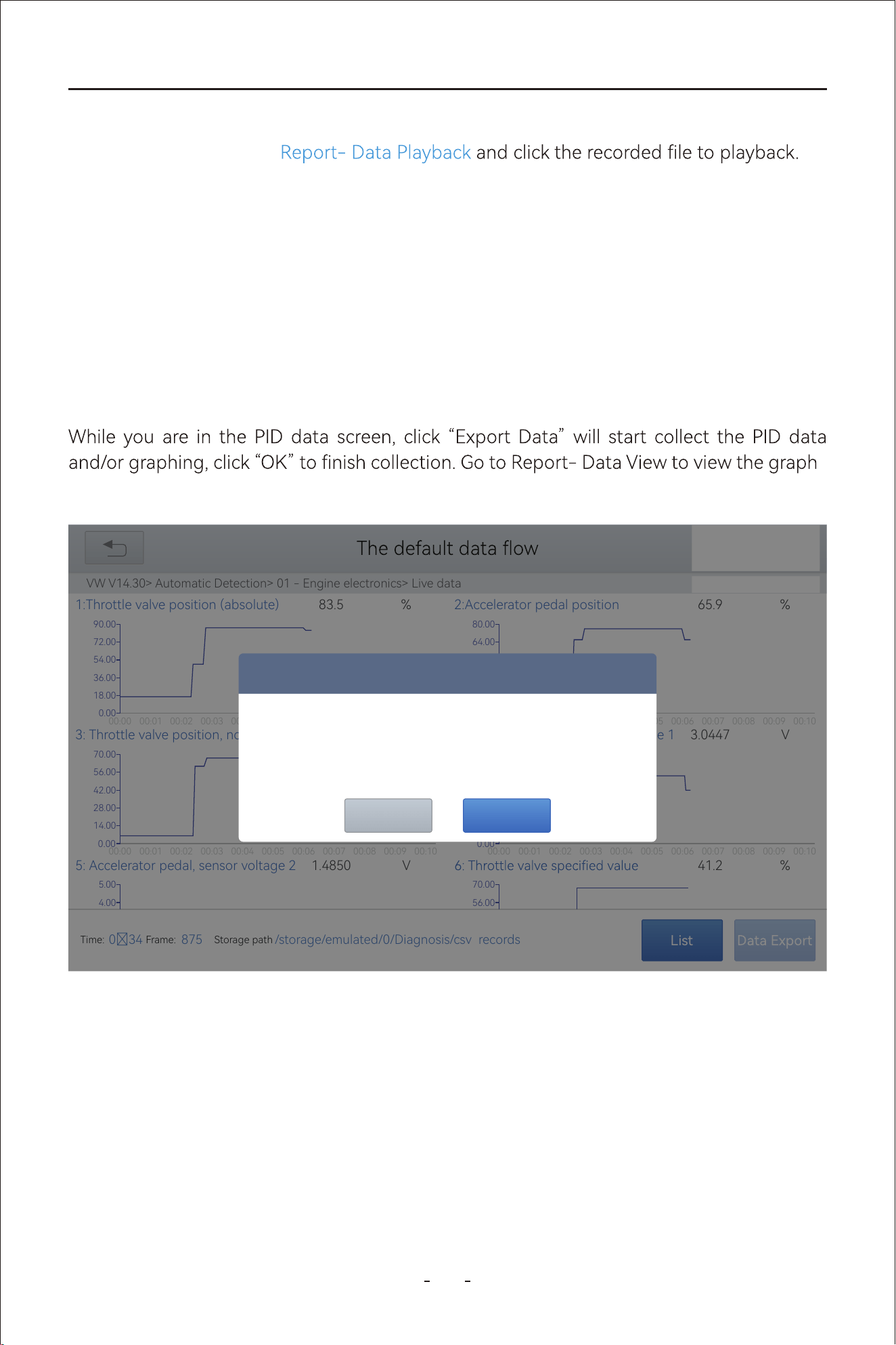
4.12.17 Expo Data as CSV & Data View
41
VD80 BT Diagnostic Tool
The Diagnostic Tool allows recording the PID data or graphing for later playback. To check
recorded PID data, go to
CombineCancel Selected
-
ing on the right side and PID data value (x-axis value and y-axis value) at the left side.
List
31%
VW V14.30> Automatic Detection> 01 - Engine electronics> Live data
00:00
0.00
00:01 00:02 00:03 00:04 00:05 00:06 00:07 00:08 00:09 00:10
18.00
36.00
54.00
72.00
90.00
1:Throttle valve position (absolute) 83.5 %
00:00
0.00
00:01 00:02 00:03 00:04 00:05 00:06 00:07 00:08 00:09 00:10
16.00
32.00
48.00
64.00
80.00
2:Accelerator pedal position 65.9 %
00:00
0.00
00:01 00:02 00:03 00:04 00:05 00:06 00:07 00:08 00:09 00:10
14.00
28.00
42.00
56.00
70.00
3: Throttle valve position, normed 55.7 %
00:00
0.00
00:01 00:02 00:03 00:04 00:05 00:06 00:07 00:08 00:09 00:10
1.00
2.00
3.00
4.00
5.00
4: Accelerator pedal, sensor voltage 1 3.0447 V
4.00
5.00
5: Accelerator pedal, sensor voltage 2 1.4850 V
56.00
70.00
41.2 %
Time:
034
Frame:
875
Storage path
/storage/emulated/0/Diagnosis/csv records
Prompt
Storage path
/storage/emulated/0/Diagnosis/csv_records
Click OK to end the collection
OKCANCEL
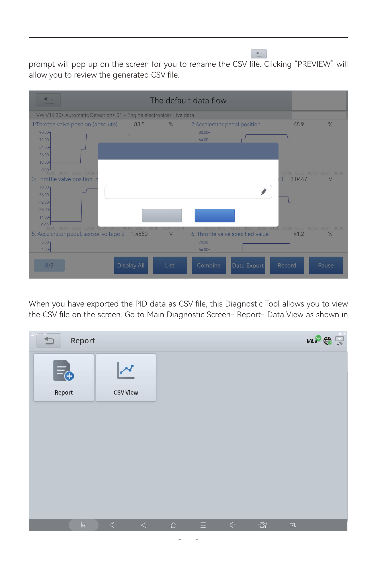
42
VD80 BT Diagnostic Tool
4.12.18 Data View
picture below:
When you have done collecting the PID data, click back icon on the top left and a
PauseRecordCombineListDisplay All
8/8
31%
VW V14.30> Automatic Detection> 01 - Engine electronics> Live data
00:00
0.00
00:01 00:02 00:03 00:04 00:05 00:06 00:07 00:08 00:09 00:10
18.00
36.00
54.00
72.00
90.00
1:Throttle valve position (absolute) 83.5 %
00:00
0.00
00:01 00:02 00:03 00:04 00:05 00:06 00:07 00:08 00:09 00:10
16.00
32.00
48.00
64.00
80.00
2:Accelerator pedal position 65.9 %
00:00
0.00
00:01 00:02 00:03 00:04 00:05 00:06 00:07 00:08 00:09 00:10
14.00
28.00
42.00
56.00
70.00
3: Throttle valve position, normed 55.7 %
00:00
0.00
00:01 00:02 00:03 00:04 00:05 00:06 00:07 00:08 00:09 00:10
1.00
2.00
3.00
4.00
5.00
4: Accelerator pedal, sensor voltage 1 3.0447 V
4.00
5.00
5: Accelerator pedal, sensor voltage 2 1.4850 V
56.00
70.00
41.2 %
Prompt
PREVIEWSAVE
VW_20240124001915
31%
Data Playback Data View
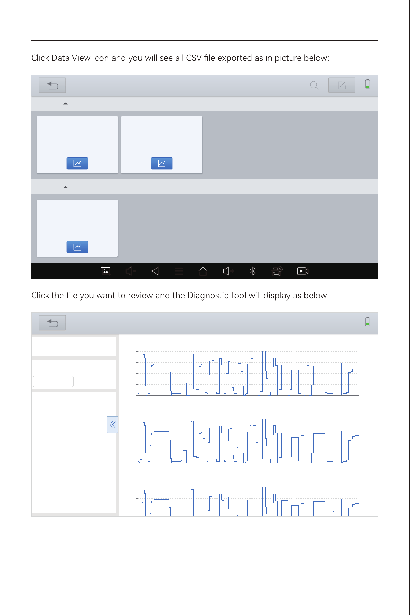
43
VD80 BT Diagnostic Tool
2024-03
VW_20240124001915
VW_20240124002124_
2024-03-24 002237
VW_20240124001915
VW_20240124002124_
2024-03-24 002337
2024-02
VW_20240124001915
VW_20240124002124_
2024-02-24 000526
31%
Data View
0.0s
14.50
7.052s 14.104s 21.156s 28.208s 35.26s 43.312s 49.364s
56.416s
63.468s 70.52s
28.62
42.75
56.88
71.00
Throttle valve position (absolute) | %
0.0s
14.50
7.052s 14.104s 21.156s 28.208s 35.26s 43.312s 49.364s
56.416s
63.468s 70.52s
26.95
39.00
51.05
63.10
Accelerator pedal position | %
0.0s
14.50
7.052s 14.104s 21.156s 28.208s 35.26s 43.312s 49.364s
56.416s
63.468s 70.52s
28.40
28.40
40.65
52.90
Throttle valve position: normed | %
31%
Data View
VW_20240124002124_17060
84557523.csv
x-axis
0 s
y-axis
Accelerator pedal position
16.5
Throttle valve position
5.9
Accelerator pedal
0.8673
Accelerator pedal
0.4428
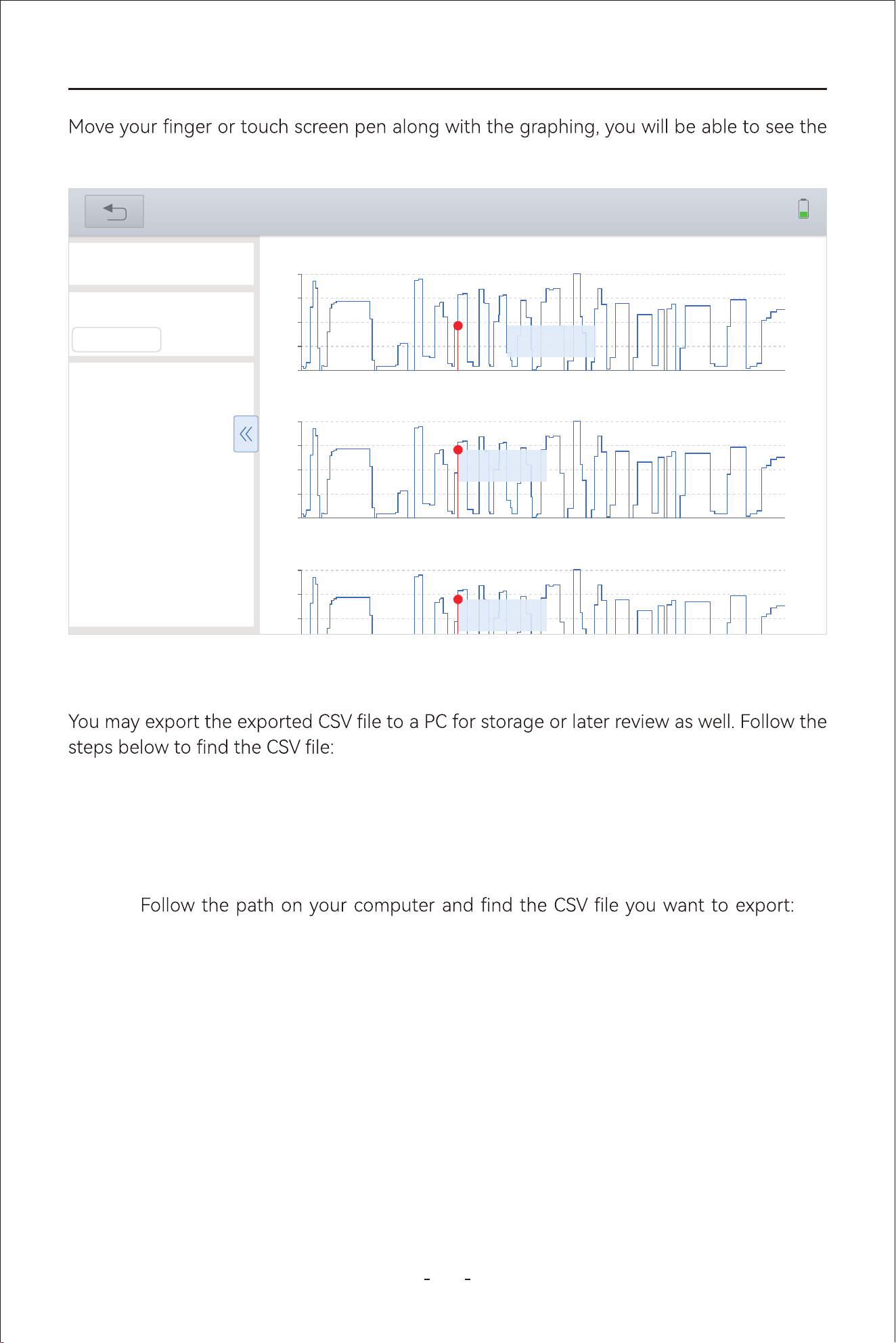
4.12.19 Expo CSV File to a PC
44
VD80 BT Diagnostic Tool
Step 1: Connect the Diagnostic Tool to a PC through the USB Type-C cable.
Step 2: Swipe down from the upper left/right corner of the Diagnostic Tool and enable
“Data Transfer”.
Step 3:
My
computer- VD80 BT- Internal Shared Storage- Diagnosis- csv_records, select the
csv le you want to expo and copy it to your PC memo.
real-time values for PID data at the left column, as shown in picture below:
0.0s
14.50
7.052s 14.104s 21.156s 28.208s 35.26s 43.312s 49.364s
56.416s
63.468s 70.52s
28.62
42.75
56.88
71.00
Throttle valve position (absolute) | %
0.0s
14.50
7.052s 14.104s 21.156s 28.208s 35.26s 43.312s 49.364s
56.416s
63.468s 70.52s
26.95
39.00
51.05
63.10
Accelerator pedal position | %
0.0s
14.50
7.052s 14.104s 21.156s 28.208s 35.26s 43.312s 49.364s
56.416s
63.468s 70.52s
28.40
28.40
40.65
52.90
Throttle valve position: normed | %
31%
Data View
VW_20240124002124_17060
84557523.csv
x-axis
22.75 s
y-axis
Accelerator pedal position
49.0
Throttle valve position
34.9
Accelerator pedal
2.5992
Accelerator pedal
1.3327
X : 22.75 (s)
Y : 40.8 | %
X : 22.75 (s)
Y : 49.0 | %
X : 22.75 (s)
Y : 34.9 | %
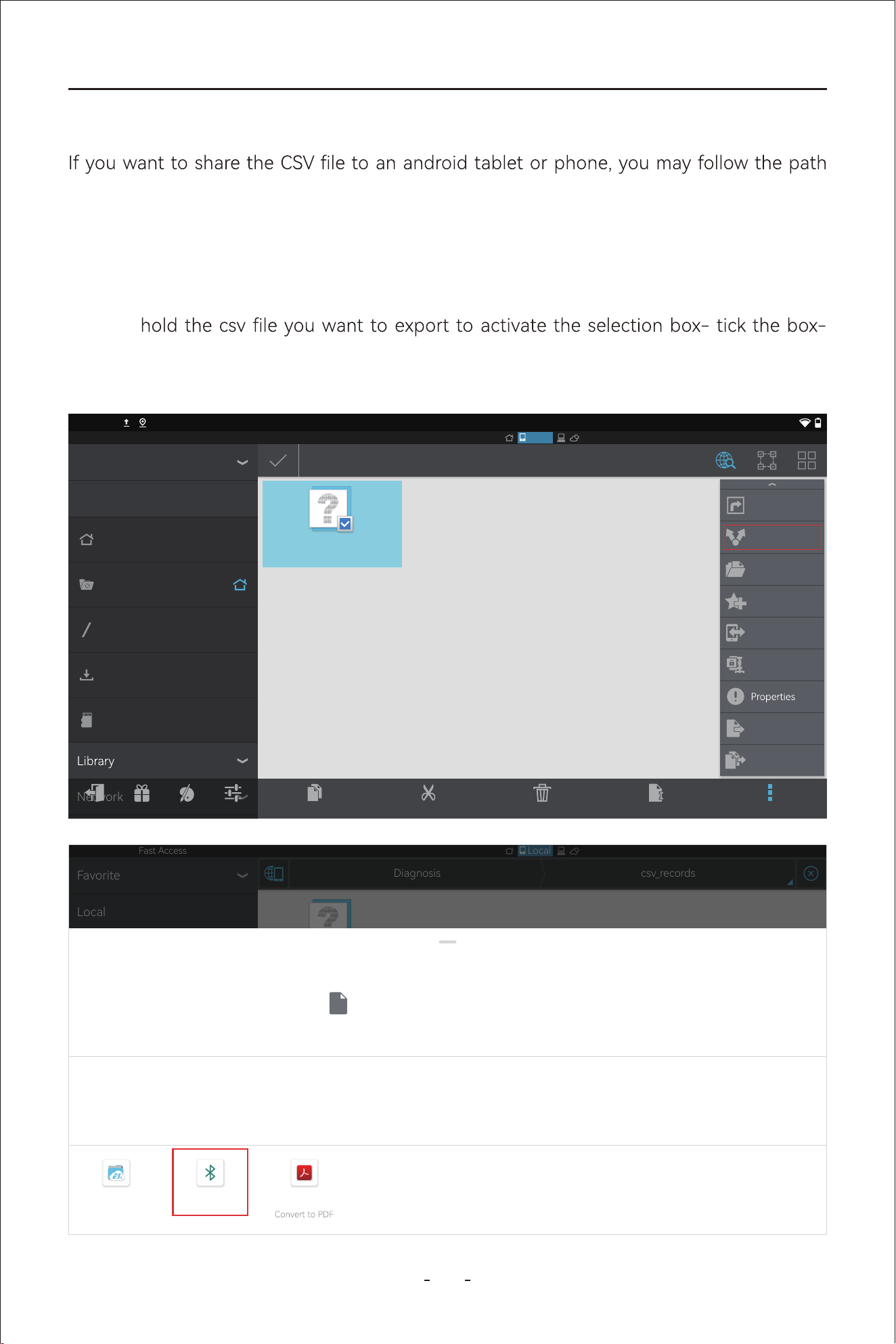
45
VD80 BT Diagnostic Tool
Step 1: Swipe up the hidden toolbar and click home icon to go to main screen of the
android tablet.
Step 2: Click “ES File Explorer”- “Local”- “Home”- ”Diagnosis”-”csv_records”-Press and
Click “More” at the bottom left of the screen- “Share”- “Bluetooth”- select the
device you want to share to.
below:
Fast Access
Local
2:40PM
VW_20240320160225_1
710921785636.csv
1/1
Favorite
Local
Network
Homepage
Home
Device
Download
0
Exit Recomme... Theme Settings
Copy
Cut
Delete
Rename
More
Add to desktop
Share
Open As
Add to favorite
Send
Compress
Move to
Copy to
Fast Access
Local
csv_recordsDiagnosis
Favorite
Local
Network
Homepage
Home
Device
Download
0
VW_20240320160225_1
710921785636.csv
Share
VW_20240320160225_1710921785636.csv
Direct share not available
ES File Explorer
Send by LAN
Bluetooth Adobe Acrobat
4.12.20 Share CSV le via Bluetooth
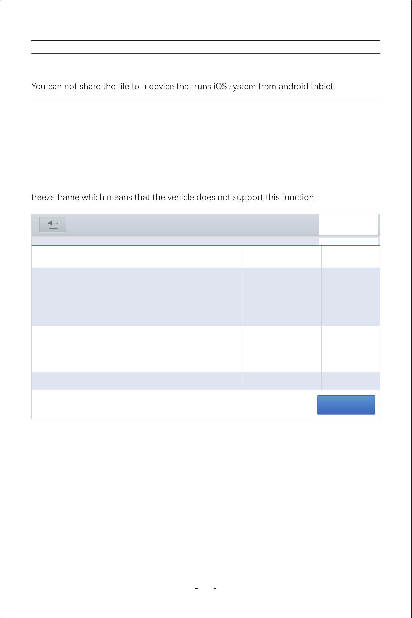
46
VD80 BT Diagnostic Tool
4.12.22 Freeze Frame
When a fault code is triggered, the vehicle ECU will save related data at that moment to
generate a freeze frame. It is usually used to analyze the root cause that triggers the fault
code, together with fault codes and PID data.
Freeze frame displayed varies across vehicles. Some vehicles may not have the option of
Note:
Read freeze frame
RENAULT V9.93> Automatic Detection> Duster ii ph> System Selection> Injection
31%
Read trouble code
Refrigerant pressure
sensor voltae
DF1068
Current
Accelerator pedal
position
fault on gangs 1 and 2
of the pedal
potentiometer
DF887
Current
Pedal potentiometer
circuit track 1
Signal outside lower
limit
DF974
Current
Pedal potentiometer
sensor voltae
4.12.21 Freeze Frame
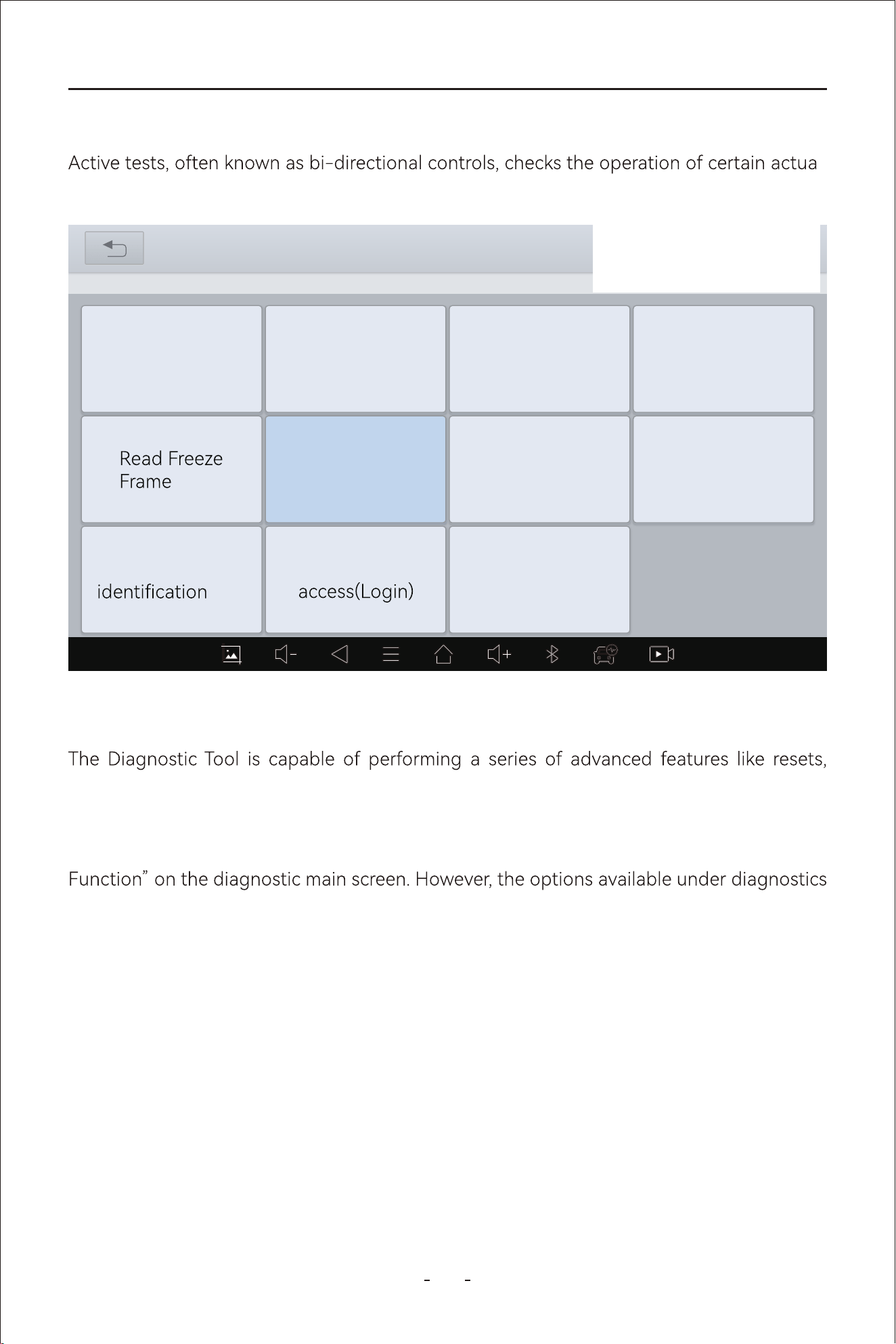
47
VD80 BT Diagnostic Tool
4.12.22 Active Tests(Bi-Directional Controls)
-
tors, such as solenoid, valves and relays.
4.12.23 Special Functions
relearns, matchings, adaptations, initializations and etc. The menu displayed varies across
vehicles.
The special functions listed under diagnostic menu have some in common with “Special
is a lot more than that on the main diagnostic screen.
31%
25 - Fan Control
VW V14.30> Automatic Detection> 25-Fan Control
Actuation Test
Read Throuble
Code
Display advanced
Clear Trouble
Code
Live Data
Read ECU
Information
Adaptation
Basic setting
Security
Coding
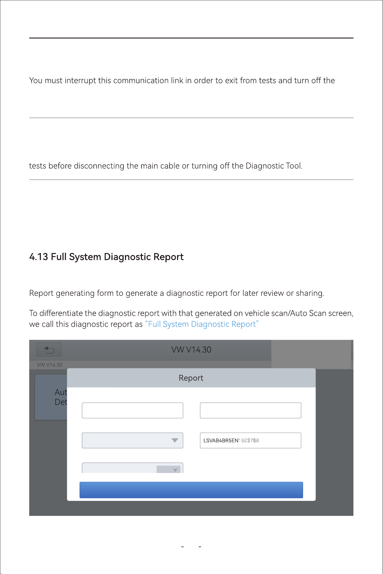
48
VD80 BT Diagnostic Tool
4.12.24 Exiting Diagnostics
Diagnostics remains open as long as there is an active communication link with the vehicle.
Diagnostic Tool. A warning message displays if you attempt to shut down while the Diag-
nostic Tool is communicating with the vehicle.
4.12.25 To Exit the Diagnostics
Click back button on the screen all the way to the main menu or kill the diagnostic program
will end interrupt the vehicle communication and exit diagnostics.
When you have done the diagnostics and exit the diagnostics all the way back to the main
diagnostic screen, input the VIN number, mileage and model year and click “OK” in the
.
Note:
Damage to the vehicle electronic control module (ECU) may occur if communication is dis-
rupted. Make sure the main cable is properly connected at all times during testing. Exit all
31%
VW V14.30
VW V14.30
Automatic
Detection
OK
Save as:
VW
Vehicle Name:
BR/NG-Santana NF 2013 after
VIN:
Mileage:
3833658.693
mile
Year:
2014
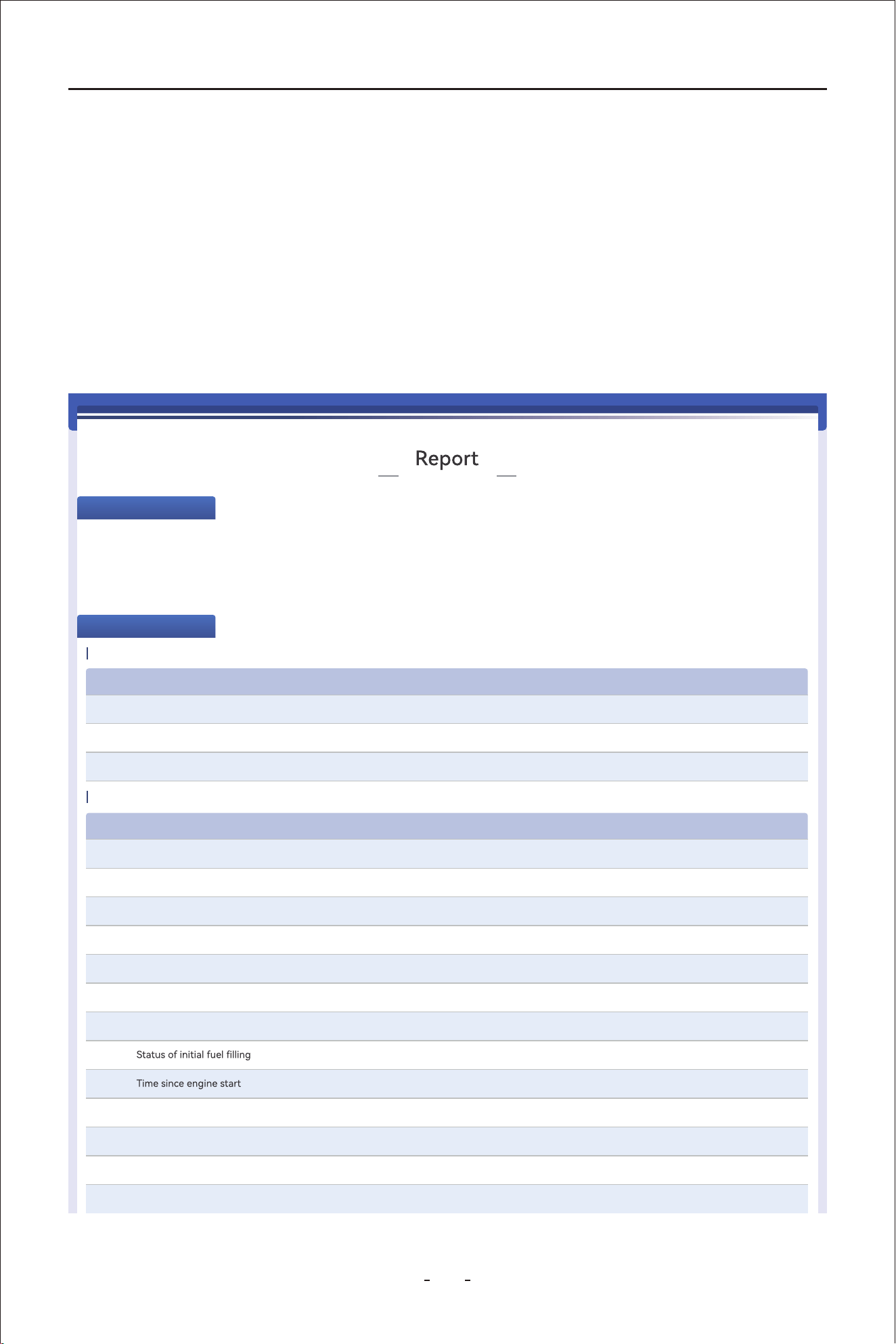
49
VD80 BT Diagnostic Tool
Go to “Repo” on the main diagnostic screen and click “Diagnosis Repo” to view all
diagnostic repos generated. Click to view the repo you would like to review according
to the date and time it’s generated or share to an email by clicking “Share by E-mail” or
print it out by clicking “Print PDF Repo”.
The repo will lists how many vehicle systems is detected, how many of them are impacted
by fault codes, how many fault codes are detected and which systems are fault impacted
and which are not. A typical “Full System Diagnostic Repo” is as shown in picture below:
2024-03-08 18:01
Vehicle information
Vehicle
Name
:
BR/NG-Santana NF 2013 after
Diagnosis
Route
:
SHVW->BR/NG-Santana NF 2013 after>2014 (E)
Year: 2014 VIN: LSVAB4BR5EN152378
SN: VD80 BT-V12345
Mileage: 617440km
01-Engine electronics
NO.
Trouble Code Trouble Code Descriptions Trouble Code status
1
U042300
[004197]
Invalid Data Received From,Instrument Panel Cluster Control Module
Passive/Sporadic
2
U042300
[0041A3]
Invalid Data Received From,Instrument Panel Cluster Control Module
Passive/Sporadic
3
U042300
[0041A2]
Invalid Data Received From Body Conntrol Module
Passive/Sporadic
NO.
Trouble Code Value Unit
Maximum
Value
1
12.516 V13.771Voltage terminal 30 11.267
2
0 1/min0Engine rpm 0
3
23 deg C25Coolant temperature 21
4
not activeStatus of actuator test
5
Function not availableNumber of parameterization attempts
6
Function not availableNumber of successful parameterization attempts
7
0 km/h0Vehicle speed 0
8
DEFAULT
9
0 s0
0
10
16.9 %Throttle calve position (absolute)
11
0.0 %Absolute load value
12
0.0 %Normed load value
13
14.9 %Accelerator pedal position
Maximum
Value
Live Data
Trouble Code
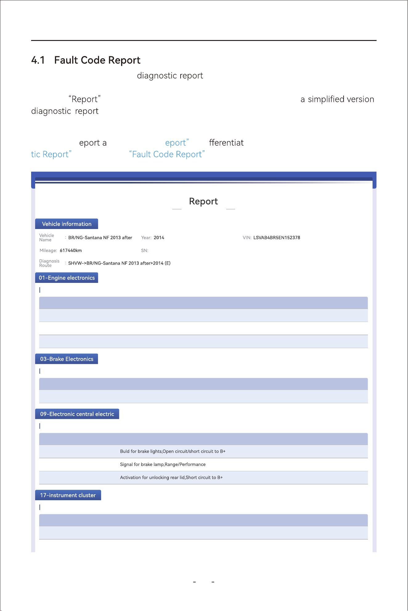
50
VD80 BT Diagnostic Tool
4
The other way to generate is through the vehicle scan/Auto Scan result
screen. When you have done scanning all available vehicle electronic control modules, a
generate
option is available at the bottom which generates
that only displays the fault codes retrieved and the vehicle systems
impacted.
We call this r
s “Fault Code R to di e it from the “Full System Diagnos-
. And a typical is as shown in picture below:
2024-03-08 18:01
NO.
Trouble Code Trouble Code Descriptions Trouble Code status
1
U042300
[004197]
Invalid Data Received From,Instrument Panel Cluster Control Module
Passive/Sporadic
2
U042300
[0041A3]
Invalid Data Received From,Instrument Panel Cluster Control Module
Passive/Sporadic
3
U042300
[0041A2]
Invalid Data Received From Body Conntrol Module
Passive/Sporadic
Trouble Code
NO.
Trouble Code Trouble Code Descriptions Trouble Code status
1
U101300
[00019D]
Control module not coded
Active/static
Trouble Code
NO.
Trouble Code Trouble Code Descriptions Trouble Code status
1
B141A15
[00100A]
Active/static
2
B131329
[002308]
Active/static
3
B140C12
[01110A]
Active/static
Trouble Code
NO.
Trouble Code Trouble Code Descriptions Trouble Code status
1
B103E1B
[903E12]
Fuel level sensor 1,Resistance too high
Active/static
2
B103F1B
[903F12]
Outside temperature sensor,Resistance too high
Active/static
Trouble Code
VD80 BT-V12345
51
VD80 BT Diagnostic Tool
5
The Diagnostic Tool provides fast all vehicle modules scan and diagnostics. However, the
time it takes to scan & diagnostic all vehicle modules varies across vehicles. Factors that
could
the diagnostic speed includes the v ehicle communication protocol the
vehicle uses and number of vehicle control modules it’s equipped.
Generally speaking, the Diagnostic Tool scans all vehicle modules faster for vehicles using
latest vehicle communication protocols than older ones. For example, scanning a vehicle
uses CAN bus for vehicle communication takes less time than an older IOS9141 protocol.
And it takes longer time to scan a modern vehicle that has many modules equipped than a
less sophisticated vehicle that has just a few modules available.
6
In some cases, often seen in older vehicle models, vehicle manufacturers tend to integrate
two or more electronic control systems into one vehicle module, which can be confusing at
some point.
Listed below are two most common examples:
- Integrates Engine and Transmission systems.
- Integrates ABS and EPB systems.
The information above indicates that you
oil temperature under
Transmission or simi-
lar name did not appear in the diagnostic menu. And you should go to Special Function
Note:
“Fault Code
generated exiting diagnostic menu is a to show health
conditions of all vehicle systems equipped.
section and there are actually NO
or
.
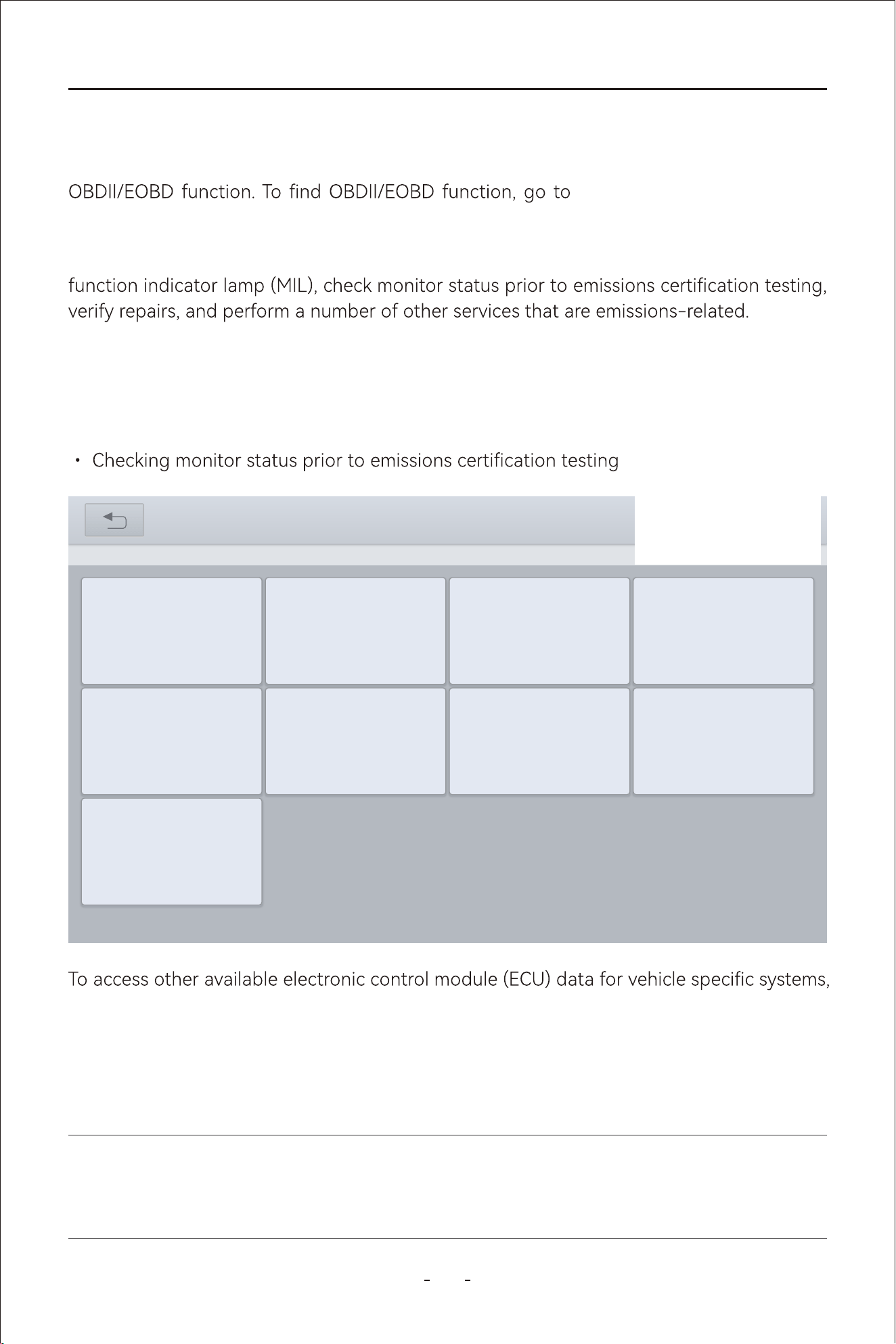
52
VD80 BT Diagnostic Tool
This chapter describes the concept, protocols, test functions and the basic operation of the
MANUAL DIAGNOSIS-Region
Selection- OBDII.
This option presents a quick way to check for DTCs, locate the cause of an illuminated mal-
parameters or enhanced diagnostics use the AUTO SCAN or MANUAL DIANGOSIS and
enter all systems diagnostics or individual system diagnostics.
The OBDII function are used to access “generic” OBDII/EOBD data for OBDII/EOBD compli-
ant vehicles that are not included in the all systems/individual systems diagnostics.
The OBDII function allows you to access “generic” OBDII/EOBD data.
Generic OBDII/EOBD data is data limited to emission related diagnostics such as:
• Checking for emissions-related diagnostic trouble codes (DTCs)
• Checking the cause of an illuminated malfunction indicator lamp (MIL)
5. OBDII/EOBD
IMPORTANT:
Generic OBDII/EOBD data are not included in the engine system diagnostic data.
31%
OBDII V21.51
OBDII V21.51> AUTO SCAN
Clear Trouble
Code(Mode04)
Read Trouble
Code(Model03/07/0A
)
Read ECU
Information(Mode0
9)
On-Board Monitor
Test(Mode06)
I/M
Readiness(Mode
01)
Live
Data(Mode 01)
Read Freeze
Frame(Model02)
Component
Test(Mode08)
O2S monitoring
Test(Mode05)
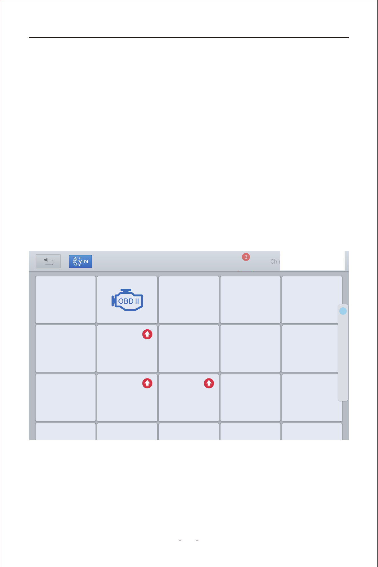
53
VD80 BT Diagnostic Tool
Global OBD uses 5 communication protocols:
SAE J1850 PWM●
SAE J1850 VPW●
ISO 14230-4(KWP2000)●
ISO 9141-2●
ISO 15765-4/SAE J2480●
5.1 OBDII Protocols
To access generic OBDII/EOBD data, please follow the steps below:
5.2 Basic Operations
Step 1: Click MANUAL DIAGNOSIS on the main diagnostic screen
Step 2: Select the region where the vehicle manufacturer is originated
Step 3: Click OBDII icon beside the DEMO
My vehicles Europe America Asia
Diagnosis for
V6.30
DEMO
Diagnosis for
V12.40
ACURA
Diagnosis for
V5.35
DAEWOO
Diagnosis for
V8.41
DAIHATSU
Diagnosis for
V12.40
HONDA
Diagnosis for
V14.10
HYUNDAI
Diagnosis for
V5.18
HYUNDAICV
Diagnosis for
V13.80
INFINITI
Diagnosis for
V9.20
ISUZU
Diagnosis for
V14.10
KIA
Diagnosis for
V14.80
LEXUS
Diagnosis for
V13.70
MAZDA
Diagnosis for
V12.20
MITSSUBISSH
I
Diagnosis for
V13.81
NISSAN
Diagnosis for Diagnosis for Diagnosis for Diagnosis for Diagnosis for
Diagnosis for
V21.51
D
H
I
K
L
M
N
P
R
S
T
A
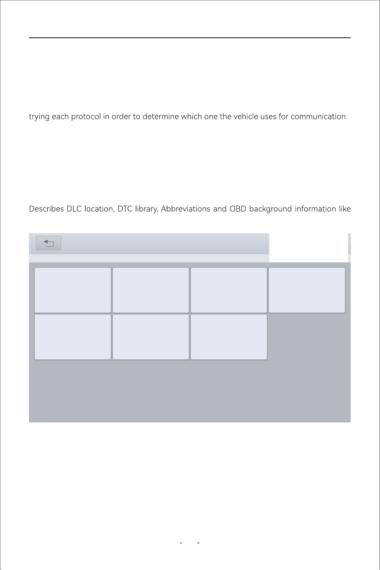
54
VD80 BT Diagnostic Tool
5.3.1 Auto Scan
When this option is selected the Diagnostic Tool attempts to establish communication
5.3.2 Protocol Selection
A communication protocol is a standardized way of data communication between an ECM
and a Diagnostic Tool. If you know which protocol your vehicle uses for communication,
select the corresponding protocol directly to establish communication.
5.3.3 Help
OBDII modes and etc.
Mode $01– Request Live Data
Mode$02– Request Freeze Frames
Mode$03– Request Stored Trouble Codes
Mode$04– Clear/Reset Stored Emissions Related Data
Mode$05– Request Oxygen Sensors Test Results
And there are two options to access the OBDII/EOBD data of the vehicle connected.
5.3 Auto Scan & Protocol Selection
5.4 10 Modes of OBDII
31%
OBDII V21.51
OBDII V21.51
ISO 14230-4SAE J1850 VPWSAE J1850 PWMAUTO SCAN
HELPISO 15765-4ISO 9141-2
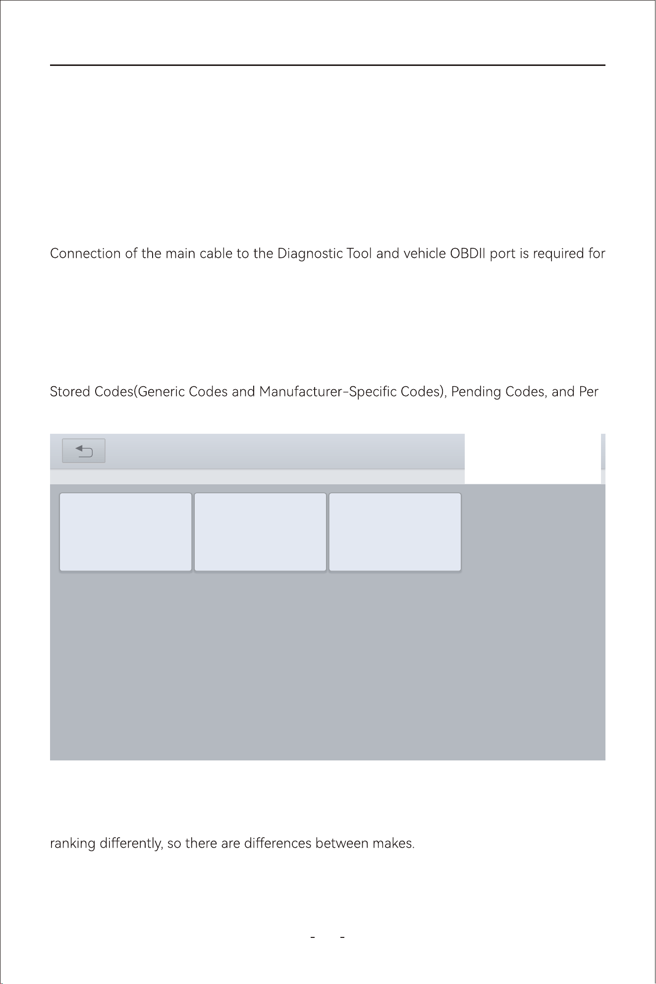
55
VD80 BT Diagnostic Tool
5.6.1 Read Trouble Code
The “Read Trouble Code” option displays a list of current emission related DTCs, including
-
manent Codes.
OBDII/EOBD Codes have a priority according to their emission severity, with higher priority
codes overwriting lower priority codes. The priority of the code determines the illumination
of the MIL and the code erase procedure. Vehicle manufacturers have implemented the
5.6 OBDII/EOBD Menu
Mode$06– Request On-Board System Tests Results
Mode$07– Request Pending Trouble Codes
Mode$08– Request Control of On-Board Systems
Mode$09– Request Vehicle Information
Mode$0A– Request Permanent Trouble Codes
OBDII/EOBD testing, see Connecting the Main Cable‚ on page 27.
5.5 Connecting the Main Cable
31%
Read Trouble Code(Mode03/07/0A)
OBDII V21.51> AUTO SCAN> Read Trouble Code(Model03/07/0A)
Pending Codes
Permanent
Codes
Stored Codes
56
VD80 BT Diagnostic Tool
5.6.1.1 Read Trouble Code
Stored codes are the current emission related DTCs from the ECM of the vehicle.
5.6.1.2 Pending Codes
The purpose of this function is to enable the Diagnostic Tool to obtain “pending” or matur-
ing diagnostic trouble codes. These are codes whose setting conditions were met during
the last drive cycle, but need to be met on two or more consecutive drive cycles before the
DTC actually sets.
5.6.1.3 Permanent Codes
This option displays a record of any “Permanent” codes. A permanent status DTC is one that
was severe enough to illuminate the MIL at some point, but the MIL may not be on at the
present time.
ECM. Permanent status codes automatically clear after repairs have been made and the
related system monitor runs successfully.
Use this function following a vehicle repair and code clearing procedure to verify test
results after a single drive cycle.
OBDII/EOBD Codes have a priority according to their emission severity, with higher priority
codes overwriting lower priority codes. The priority of the code determines the illumination
of the MIL and the code erase procedure. Vehicle manufacturers have implemented the
Diagnostic Trouble Code (DTCs) -
indicates whether the code is an SAE generic code (applies to all OBDII systems) or is spe-
. The remaining three numbers provide information regard-
below.
pending fault does not occur again within 40 to 80 warm-up cycles, the fault is auto-
●
system. If test results indicate another failure after additional driving, then a DTC is set
to indicate a faulty component or system, and the MIL is illuminated.
●
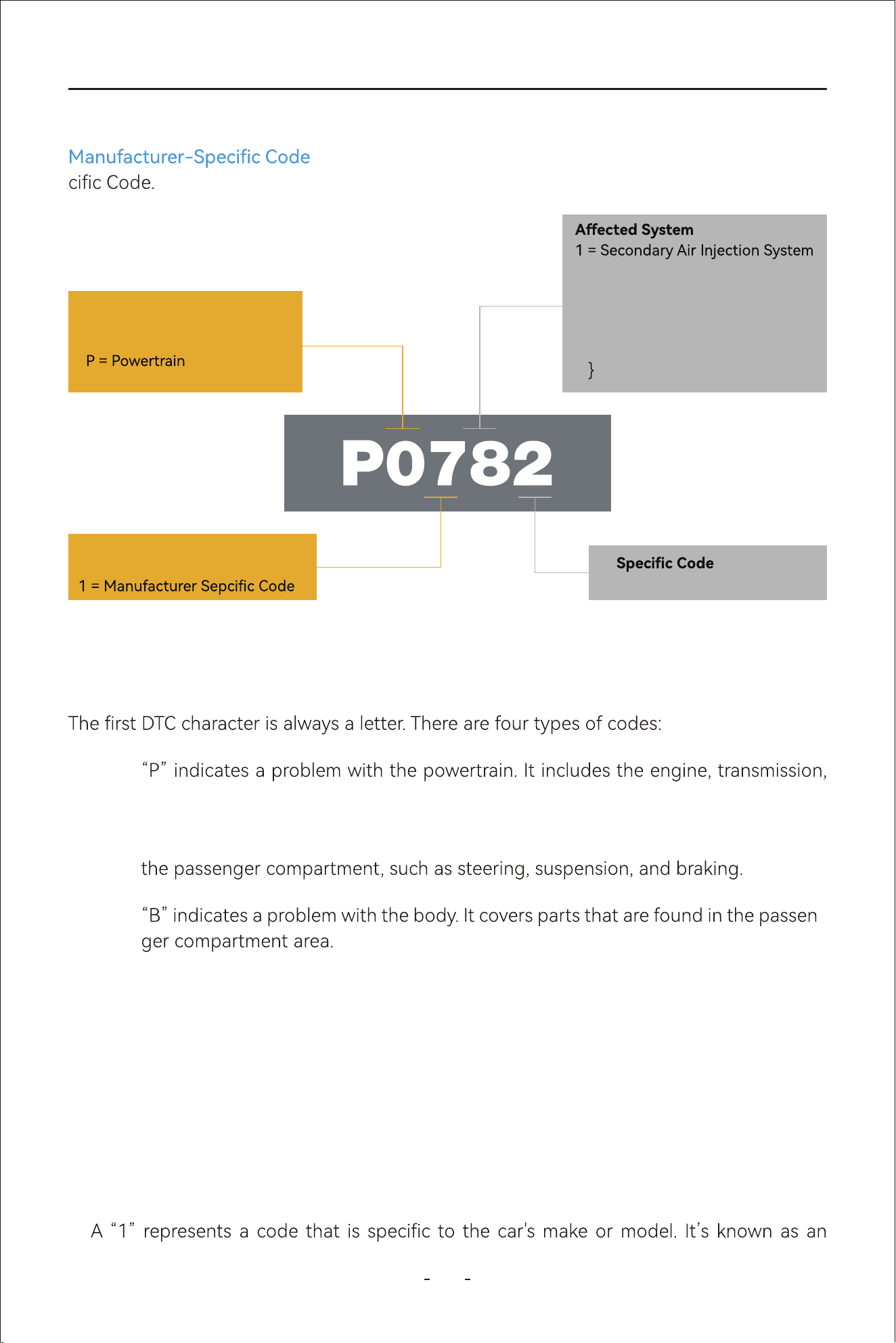
57
VD80 BT Diagnostic Tool
5.6.3.1 First DTC Character
P codes:
drivetrain, and fuel system.
C codes:“C” indicates a problem with the chassis. It refers to mechanical systems outside
5.6.3.2 Second DTC character
The second DTC character is a numeric digit, either a “0” or a “1”:
0: A “0” indicates a standard SAE international code. It’s also known as a generic code,
meaning that it applies to all vehicles following the OBDII international standard.
1:
B codes: -
U codes:“U” indicates a problem with the vehicle’s onboard computers and integration
functions that the OBD manages.
5.6.3 Permanent Codes
Generic Codes -- DTCs with the second character as “0” is a Generic Code.
-- DTCs with second character as “1” is a Manufacturer-Spe-
Trouble Code System
B = Body
C = Chassis
U = Network Communication
Code Type
0 = Standardized Code (ISO/SAE)
2 = Fuel System
3 = Ignition System
4 = Exhaust Monitoring System
5 = Idle Speed Control or Cruise
Control
6 = Input/Output Signal from ECU
7
8
= Transmission System
Exact Problem Description
58
VD80 BT Diagnostic Tool
5.6.4 Clear Trouble Code(Mode $04)
5.6.3.4 Fouh and Fifth DTC Character
This option is used to clear all emission related diagnostic data, such as DTCs, freeze frame
-
plays generic OBDII/EOBD data only, clearing codes erases all of the stored data, including
any enhanced codes and freeze frame information.
5.6.5 Live Data(Mode $01)
Use this function to display the current emission related data from the selected electronic
control module (ECM) of the vehicle. The main body of the screen has two main columns;
the left-hand column is a description of the parameter and the right-hand column is the
parameter value and unit or state.
5.6.6 Read Freeze Frame(Mode $02)
Freeze frame data provides a “snapshot” of critical parameter values at the time a DTC set.
This function is used to display freeze fame data for any stored emission related diagnostic
-
5.6.3.3 Third DTC character
If the second DTC character is a “0,” then the third character helps you determine which
subsystems are malfunctioning. There are eight numbers:
enhanced code, meaning it doesn’t fall under an SAE standard. If you see a “1,” reach out
to the vehicle manufacturer directly for more information.
1:Fuel and air metering injection system
2:Fuel and air metering (injection system)
6:Computer output circuit
7-8:Transmission

59
VD80 BT Diagnostic Tool
5.6.7 I/M Readiness(Smog Check)
This function is used to check the readiness of the monitoring system. It is an excellent
function to use prior to having a vehicle inspected for compliance to a state emissions pro-
gram. Selecting I/M Readiness opens a sub-menu with two choices:
DTCs, those that have a greater impact on vehicle emission, have a higher priority. In these
cases, the highest priority DTC is the one for which the freeze frame records are retained.
31%
I/M Readiness(Mode01)
OBDII V21.51> AUTO SCAN> I/M Readiness(Mode01)
Monitor status since
DTCs cleared
Monitor status this
driving cycle
60
VD80 BT Diagnostic Tool
5.6.7.1 Since DTCs Cleared
Displays the status of monitors since the last time the DTCs are erased
GraphPauseData recording
OBDII V21.51> AUTO SCAN > I/M Readiness(Mode01)
31%
Monitor status since DTCs cleared
Unit
ValueNameNo.
Malfunction Indicator Lamp (MIL) Status
1
MIL OFF
2
OK
Fuel system Monitoring
3
OK
Comprehensive component monitoring
4
OK
Catalyst monitoring
5
INC
Heated catalyst monitoring
6
N/A
5.6.7.2 This Driving Cycle
Displays the status of monitors since the beginning of the current drive cycle.
GraphPauseData recording
OBDII V21.51> AUTO SCAN > I/M Readiness(Mode01)
31%
Monitor status this driving cycle
Unit
ValueNameNo.
Malfunction Indicator Lamp (MIL) Status
1
MIL OFF
2
OK
Fuel system Monitoring
3
OK
Comprehensive component monitoring
4
OK
Catalyst monitoring
5
INC
Heated catalyst monitoring
6
N/A

61
VD80 BT Diagnostic Tool
5.6.8 O2S Monitoring Test(Mode $05)
This option opens a menu of tests available for checking the integrity of the oxygen sen-
31%
O2S Monitoring Test(Mode05)
OBDII V21.51> AUTO SCAN> O2S Monitiring Test(Mode05)
Bank 1-Sensor1 Bank 1-Sensor2
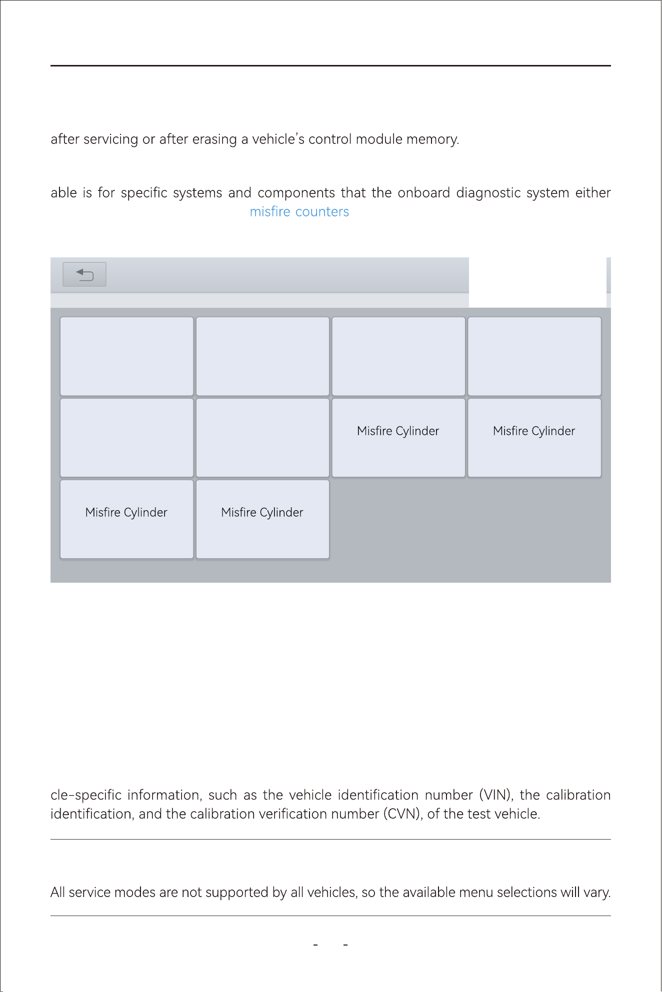
62
VD80 BT Diagnostic Tool
5.6.9 On-Board Monitor Test (Mode $06)
This function allows you to view the results of On-Board Monitor tests. The tests are useful
This function opens a menu of available test results on monitored systems. The data avail-
continuously monitors, such as , or non-continuously monitors. Making a
selection displays the test results.
5.6.10 Component Test(Mode $08)
This function enables bidirectional control (to limited extend) of the ECM. The purpose of
this function is to allow the Diagnostic Tool to control the operation of an onboard system,
test, or component, such as EVAP leakage test or other test. This function is useful in deter-
mining whether the ECM responds to a command well.
5.6.11 Read Vehicle Information(Mode $09)
The purpose of this function is to enable the Diagnostic Tool to request and display vehi-
IMPORTANT:
31%
On-Board Monitor Test(Mode06)
OBDII V21.51> AUTO SCAN> On-Board Monitor Test(Mode06)
Exhaust Gas Sensor
Monitor B1S1
Exhaust Gas Sensor
Monitor B1S2
Exhaust Gas Sensor
Heater Monitor
B1S1
Exhaust Gas Sensor
Heater Monitor
B1S2
1 Data 2 Data
3 Data 4 Data
Catalyst Monitor
Bank 1
VVT Monitor
Bank 1
63
VD80 BT Diagnostic Tool
“Special Function”. A typical special function screen is a series of menu driven executive
commands. By following the on-screen instructions to select appropriate execution
If you want more information, please provide the device serial number, vehicle VIN code and
the required function to our suppo team: suppo@vdiagtool.com.
In general, please follow the prompts on the device screen to peorm the required function.
6.
Because the conguration of each vehicle model varies, it is impossible to list the specic
operation steps for each special function.
●
After changing engine oil or electric appliances that monitor oil life, you need to reset
●
The Diagnostic Tool can be used to reset the engine oil life system, which calculates the
oil life reminder must be reset each time the oil is changed so that the system can calculate
when the next oil change is due.
6.1 Oil Reset
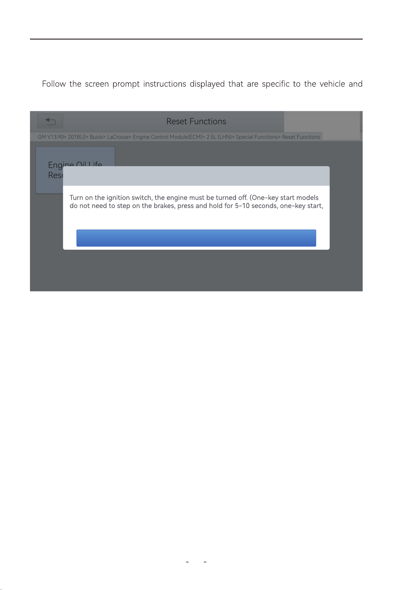
64
VD80 BT Diagnostic Tool
Enter the Oil Reset menu and select vehicle model according to the vehicle being tested.1:
press OK after completing the instructions shown.
2:
The operation guidelines of the Oil Reset function are shown as below:
31%
Reset Functions
GM V13.90> 2018(J)> Buick> LaCrosse> Engine Control Module(ECM)> 2.5L (LHN)> Special Functions> Reset Functions
Engine Oil Life
Reset
Engine Oil Life Reset
turn on the ignition switch)
Yes
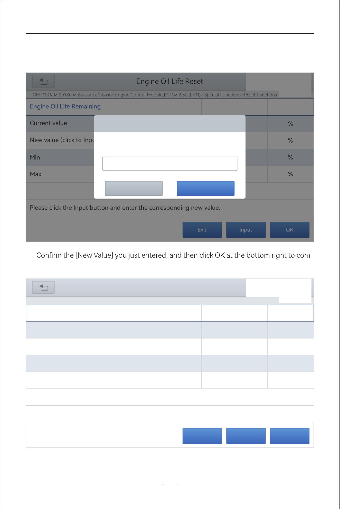
65
VD80 BT Diagnostic Tool
Enter maintenance mileage reset menu.3:
Click INPUT and enter a reasonable value of remaining oil life and press OK4:
-
plete the procedure.
5:
OKInputExit
GM V13.90> 2018(J)> Buick> LaCrosse> Engine Control Module(ECM)> 2.5L (LHN)> Special Functions> Reset Functions
31%
Engine Oil Life Reset
Current value
%
50
Engine Oil Life Remaining
Min
%
0
New value (click to Input to change the value)
%
100
Max
%100
Please click the Input button and enter the corresponding new value.
OKInputExit
GM V13.90> 2018(J)> Buick> LaCrosse> Engine Control Module(ECM)> 2.5L (LHN)> Special Functions> Reset Functions
31%
Engine Oil Life Reset
Current value
%
*
Engine Oil Life Remaining
Min
%
*
New value (click to Input to change the value)
%
*
Max
%100
Please click the Input button and enter the corresponding new value.
Engine Oil Life Reset
OKCancel
Engine Oil Life Remaining
100
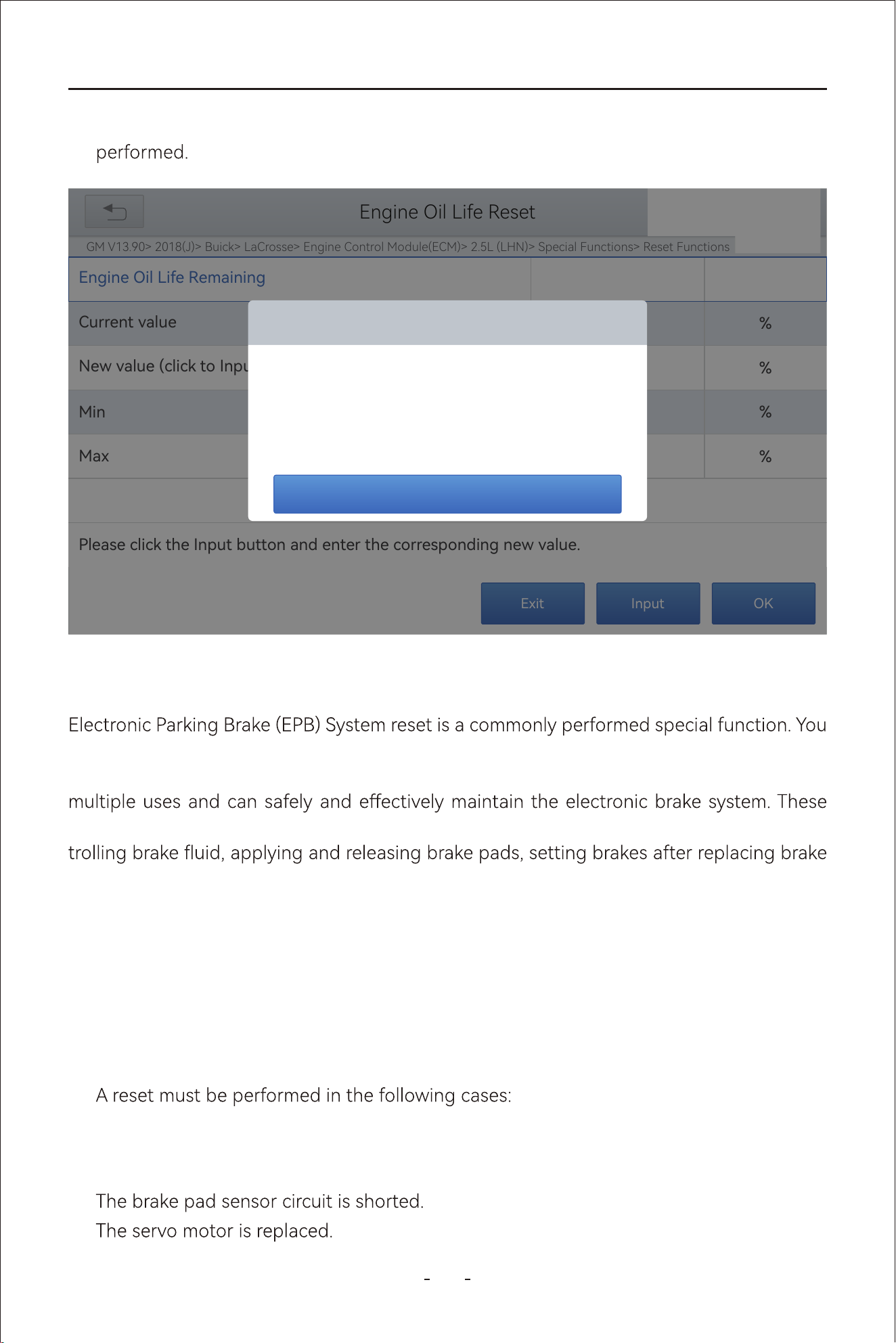
66
VD80 BT Diagnostic Tool
If the brake pad wears the brake pad sense line, the brake pad sense line will send a
signal to the onboard computer asking for replacing the brake pad. After replacing the
brake pad, you must reset the brake pad to clear the trouble code.
1.
2.
Message of ‘Write successfully’ displays when Oil Reset function has been successfully
6:
The brake pad and brake pad wear sensor are replaced.●
The brake pad indicator lamp is on.●
●
●
can use this function to reset the electronic parking brake system and brake pads (retrac-
tion, release of the brake pump), G-sensor and body angle calibration. This function has
applications include deactivating and activating brake control systems, assisting in con-
discs or brake pads, etc.
Otherwise, vehicle will continue to falsely notify the driver that the brake pads are in need
of replacement.
6.2 EPB
OKInputExit
GM V13.90> 2018(J)> Buick> LaCrosse> Engine Control Module(ECM)> 2.5L (LHN)> Special Functions> Reset Functions
31%
Engine Oil Life Reset
Current value
%
*
Engine Oil Life Remaining
Min
%
*
New value (click to Input to change the value)
%
*
Max
%100
Please click the Input button and enter the corresponding new value.
Engine Oil Life Remaining
OK
Write sussessfully
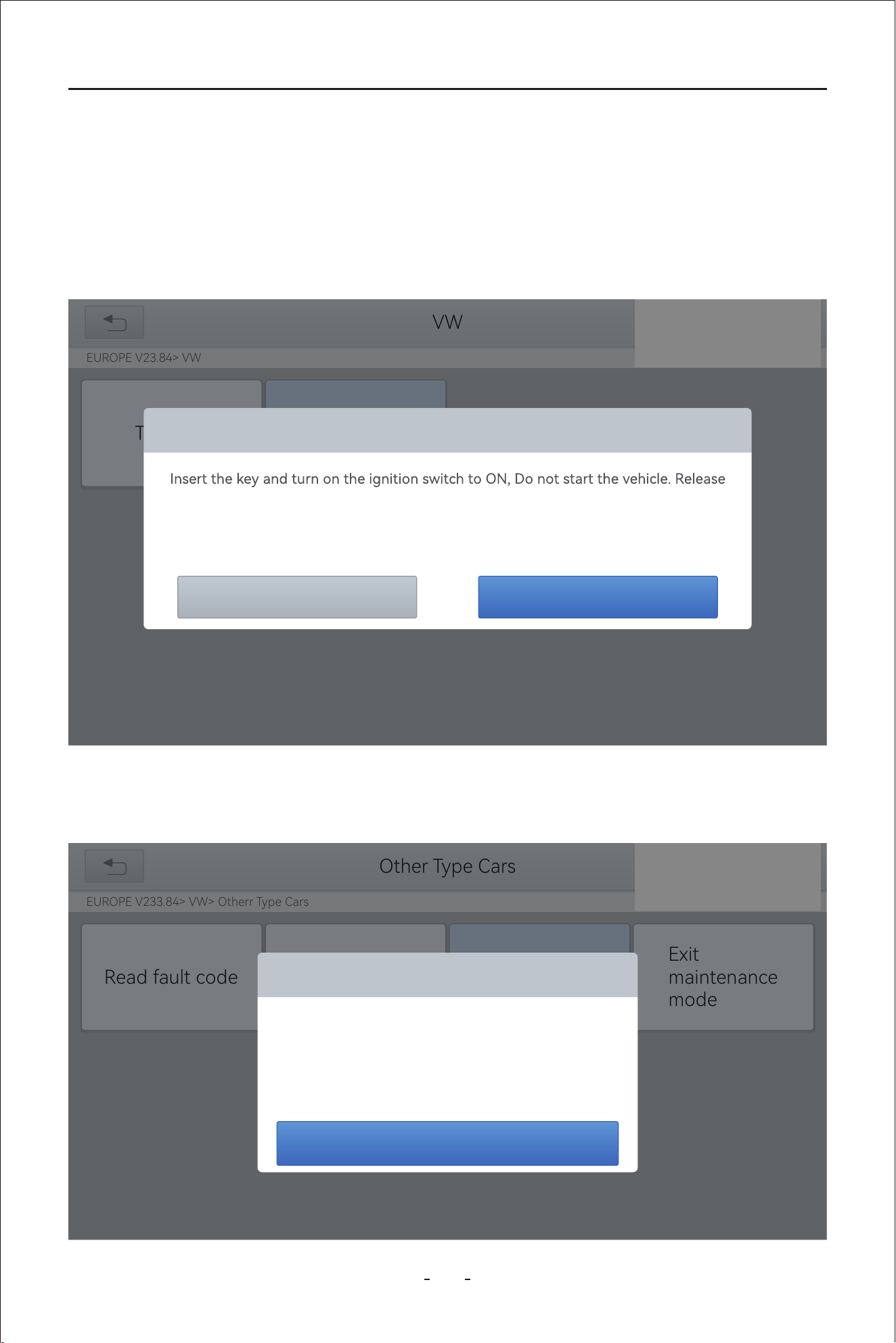
67
VD80 BT Diagnostic Tool
The operation guidelines of the EPB function are shown as below:
Enter the EPB menu and choose relevant models according to the vehicle being
tested.
Step 1.
Follow the instructions displayed and press YES after completing the instructions
shown.
Step 2.
Enter the Enter maintenance mode menu and release the handbrake brake. And
press OK after completing the instructions shown.
Step 3.
31%
VW
EUROPE V23.84> VW
Trouble
Other Type Cars
the handbrake at the same time!
If the replacement of the brake pads is completed, The clectronic brake fault light is
still on, After driving for a while, The fault light will disappear.
YesNo
31%
Other Type Cars
EUROPE V233.84> VW> Otherr Type Cars
Read fault code
Exit
maintenance
mode
Enter maintenance mode
Please release the handbrake brake
OK
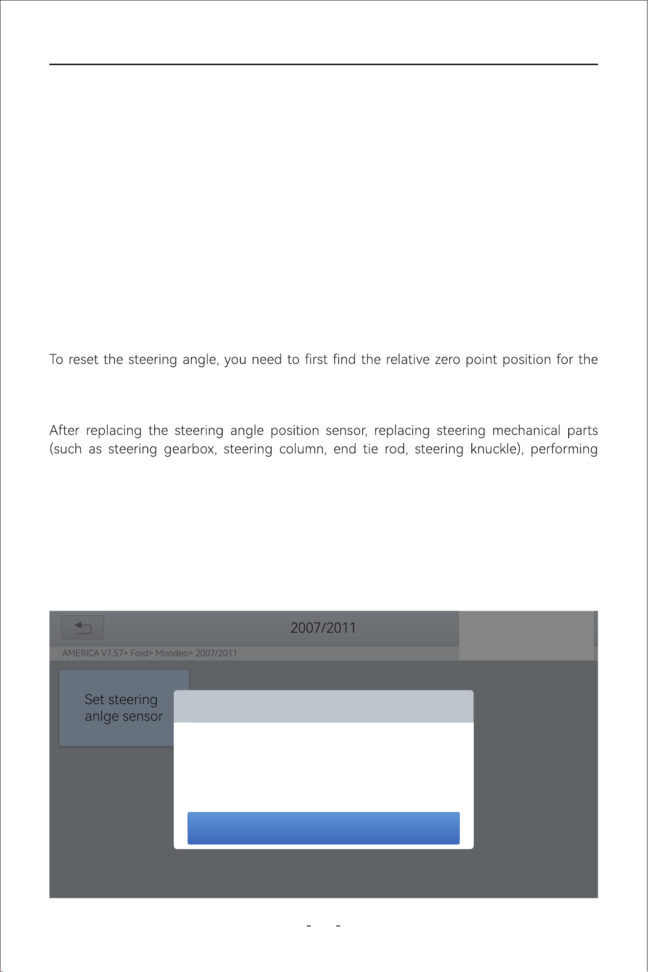
68
VD80 BT Diagnostic Tool
The operation guidelines of the SAS function are shown as below:
Enter the SAS menu and choose the vehicle model according to the vehicle being
tested.
Step 1.
Enter the Set steering angle sensor menu and follow the instructions displayed.Step 2.
Wait until the message of “Successful operation” pops up. And press OK to exit the
menu.
Step 4.
Enter the Exit maintenance mode menu and wait until the message of “Successful
operation” pops up.
Step 5.
Steering Angle Sensors (SAS) System Calibration permanently stores the current steering
wheel position as the straight-ahead position in the SAS EEPROM. Therefore, the front
wheels and the steering wheel must be set exactly to the straight-ahead position before
calibration. In addition, the VIN is also read from the instrument cluster and stored perma-
nently in the SAS EEPROM. On successful completion of calibration, the SAS fault codes will
be automatically clea
red.
vehicle to drive in a straight line. Taking this position as a reference, the ECU can calculate
the accurate angle for left and right steering.
four-wheel alignment, or repairing the car body, you must reset the steering angle.
6.3 SAS
31%
2007/2011
AMERICA V7.57> Ford> Mondeo> 2007/2011
Set steering
anlge sensor
Set steering angle sensor
Turn the ignition switch ON,press[OK] button to continue.
OK
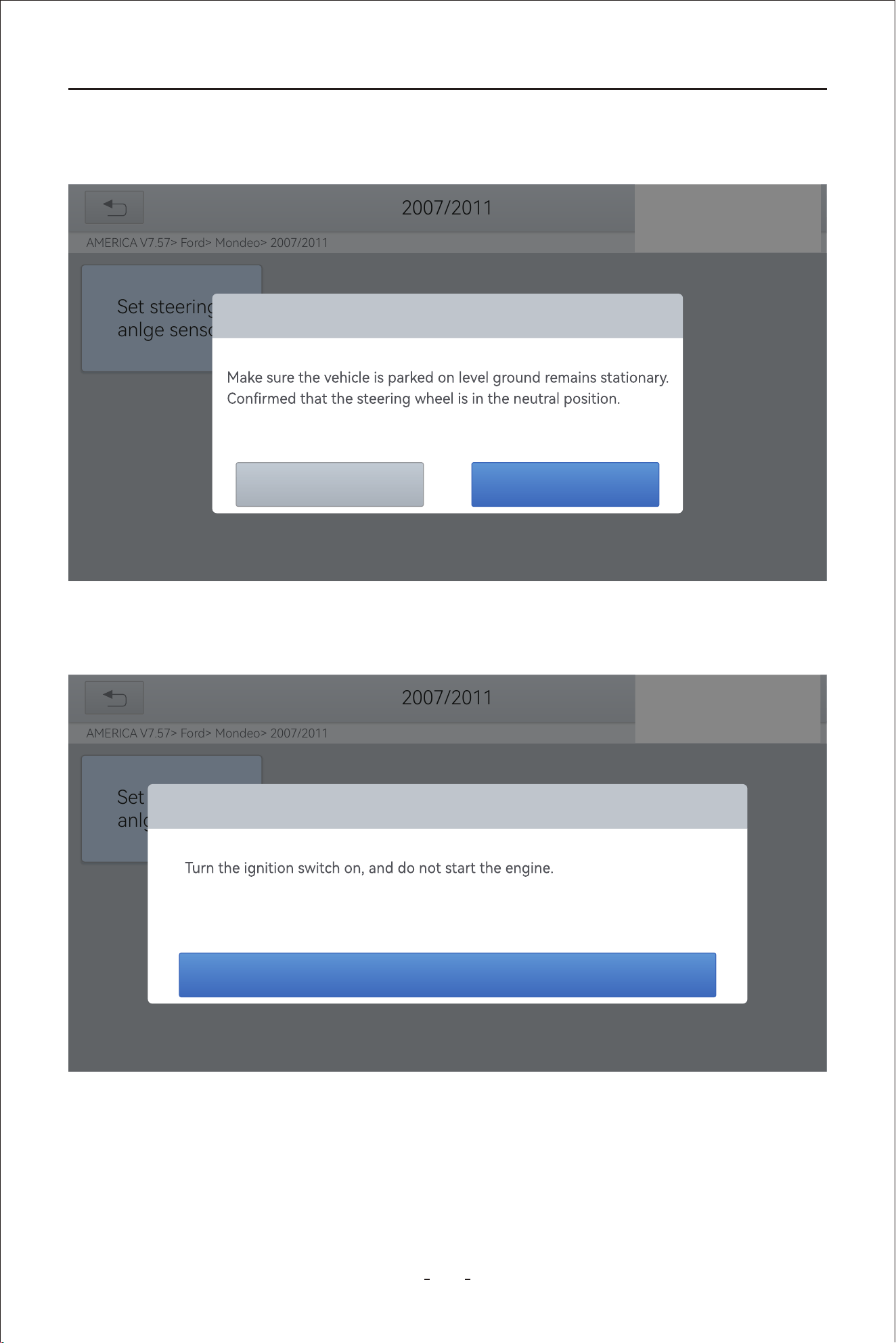
69
VD80 BT Diagnostic Tool
Wait until the following instruction is displayed and press Yes after completing the
instructions shown.
Step 3.
31%
2007/2011
AMERICA V7.57> Ford> Mondeo> 2007/2011
Set steering
anlge sensor
Set steering angle sensor
Whether to continue?
YesNo
Follow the instructions displayed and press OK after completing the instructions
shown.
Step 4.
31%
2007/2011
AMERICA V7.57> Ford> Mondeo> 2007/2011
Set steering
anlge sensor
Set steering angle sensor
The steering wheel is rotated 10 degrees left and right, then back to the middle
position.
OK
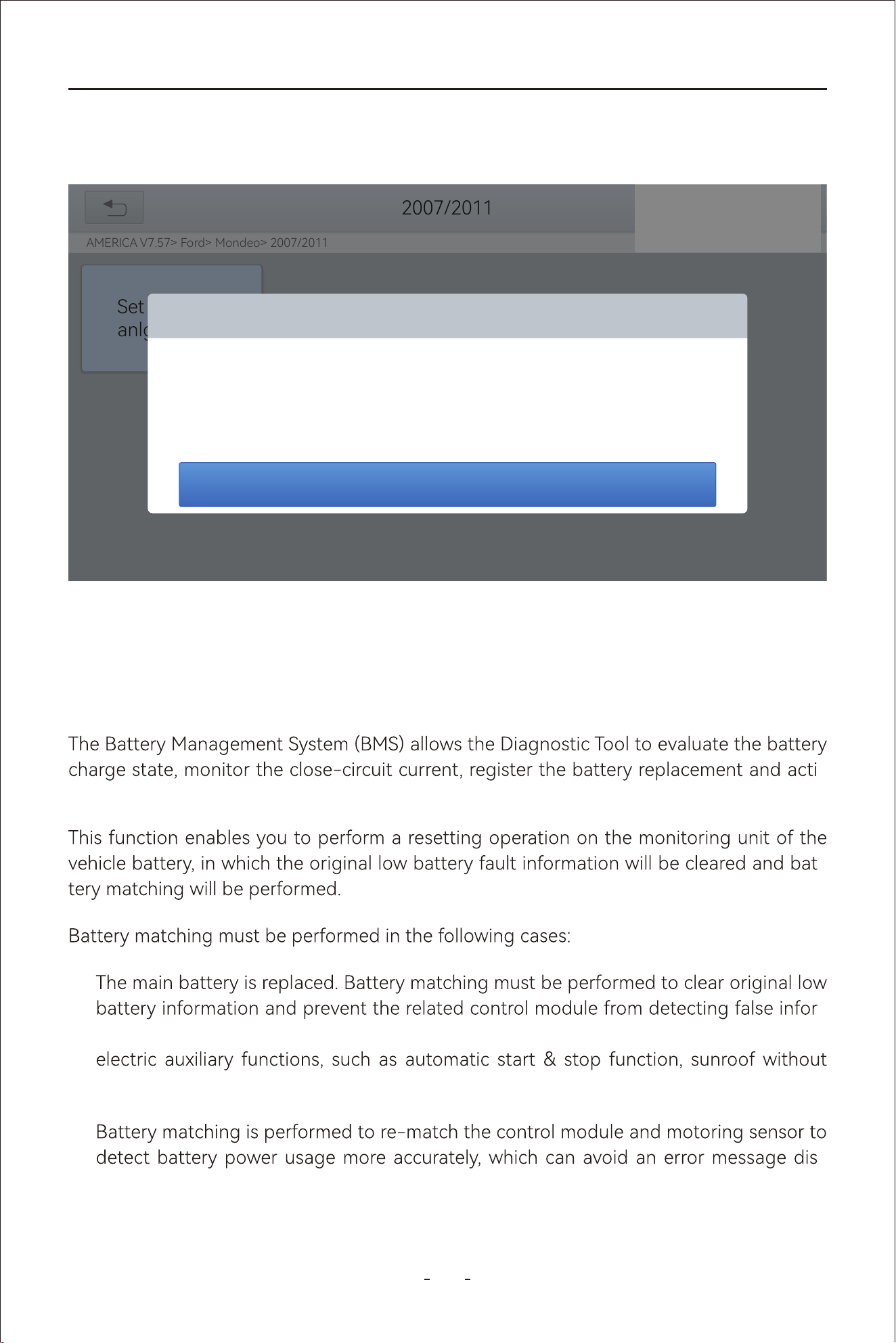
70
VD80 BT Diagnostic Tool
-
mation. If the related control module detects false information, it will invalidate some
one-key trigger function or power window without automatic function.
●
-
played on the instrument cluster
●
Message of “Function execution is completed” displayed when SAS reset function has been
successfully completed.
-
vate the rest state of the vehicle.
-
6.4 BMS Reset
Wait until the following instruction is displayed and press OK after completing the
instructions shown.
Step 5.
31%
2007/2011
AMERICA V7.57> Ford> Mondeo> 2007/2011
Set steering
anlge sensor
Set steering angle sensor
Turn the ignition switch on, and then turn the ignition switch on after 3 seconds.
OK
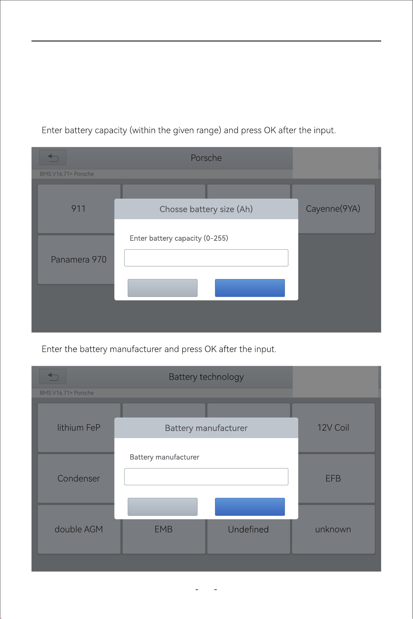
71
VD80 BT Diagnostic Tool
1. Enter the BMS Reset menu and choose relevant models according to the vehicle being
tested.
2. Turn on the ignition switch.
3. Press OK to continue the BMS function.
4.
The operation guidelines of the BMS Reset function are shown as below:
31%
Porsche
BMS V16.71> Porsche
Cayenne(9YA)SAE J1850 VPWSAE J1850 PWM911
HELPISO 15765-4Panamera 970
OKCancel
000
5.
BMS V16.71> Porsche
12V Coil
EFB
SAE J1850 VPWSAE J1850 PWMlithium FeP
double AGM
HELPISO 15765-4
unknownEMB
Condenser
31%
OKCancel
000
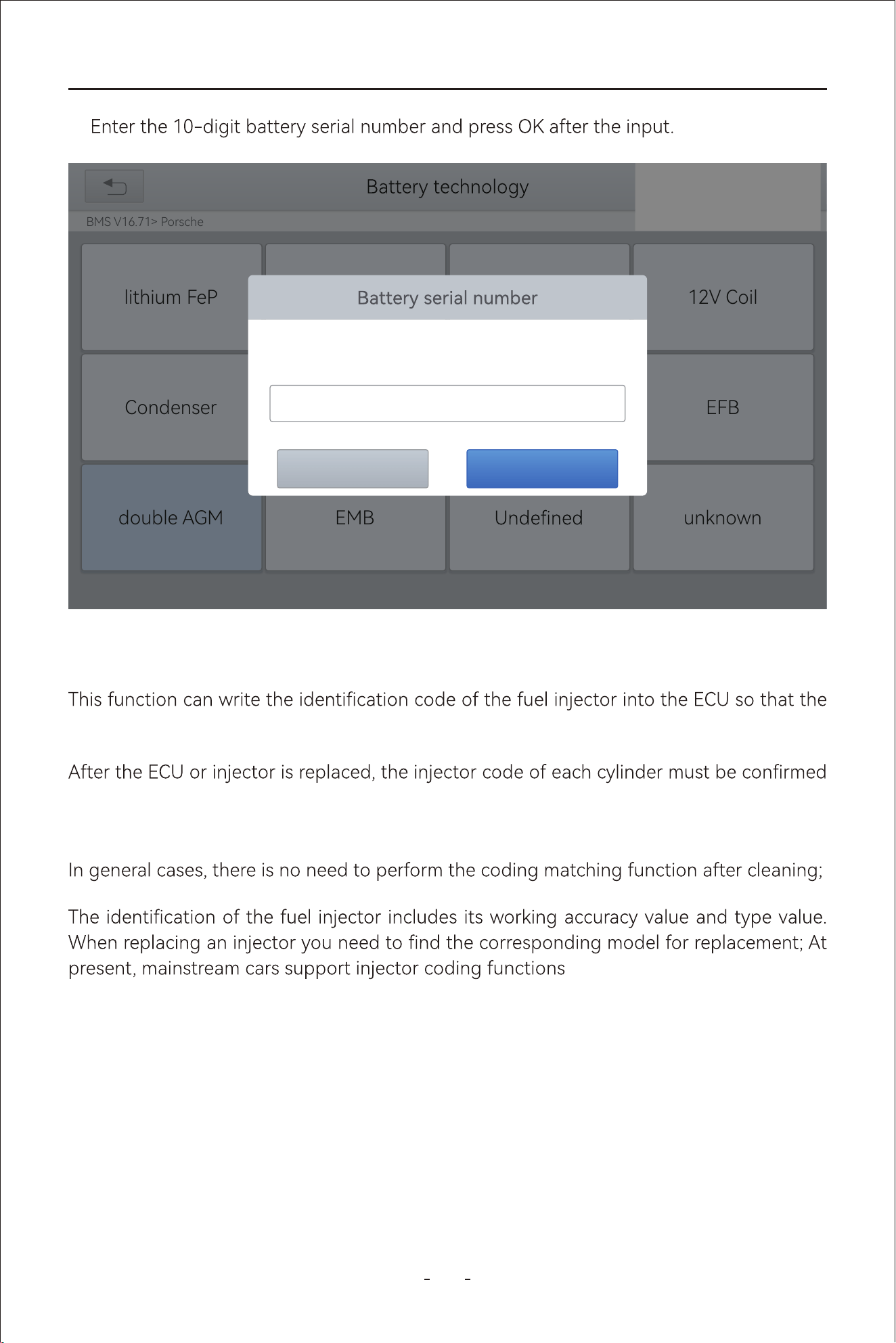
72
VD80 BT Diagnostic Tool
ECU can recognize the new injector.
or re-coded so that the cylinder can better identify injectors to accurately control fuel injec-
tion.
6.5 Injector Coding
6.
BMS V16.71> Porsche
12V Coil
EFB
SAE J1850 VPWSAE J1850 PWMlithium FeP
double AGM
HELPISO 15765-4
unknownEMB
Condenser
31%
OKCancel
Enter 10-digit serial number
0000000000
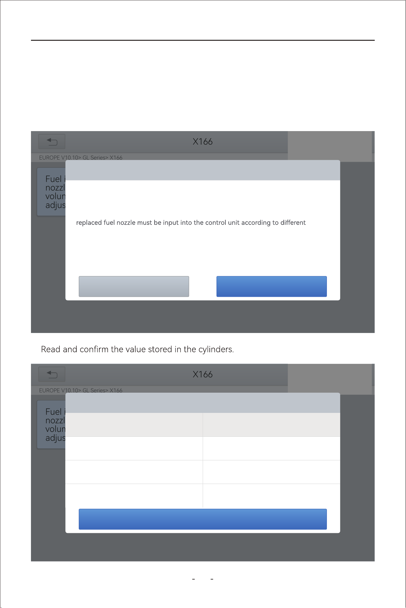
73
VD80 BT Diagnostic Tool
1. Enter the Injector coding menu and choose relevant chassis models according to the
vehicle being tested.
2. Enter the Fuel injection nozzle injection volume adjustment menu.
3. Read the note displayed carefully and press OK after the reading.
4.
The operation guidelines of the Injector Coding function are shown as below:
X166
EUROPE V10.10> GL Series> X166
31%
Fuel i
nozzl
volun
adjus
Fuel injection nozzle injection vloume adjustment
OK
Cancel
When replacing the fuel injuector,the fuel injection quantity of the injector must be
adjusted.
After replacing one or more fuel nozzles, the corresponding adjustment value of the
cylinders.
Injection The nozzle fuel injection quantity can be adjusted by manually inputting the
5-digit matching value. (Note: Please use the adjusted value printed on the fuel
injector)
X166
EUROPE V10.10> GL Series> X166
31%
Fuel inje
nozzle in
volume
adjustm
Fuel injection nozzle injection vloume adjustment
OK
The value stored in the Y76/1 (cylinder1
fuel injector) control unit:
5555N
The value stored in the Y76/2 (cylinder2
fuel injector) control unit:
5555N
The value stored in the Y76/3 (cylinder3
fuel injector) control unit:
5555N
The value stored in the Y76/4 (cylinder4
fuel injector) control unit:
5555N

74
VD80 BT Diagnostic Tool
5. Enter the Change the value of cylinder menu of the replaced injector(s), enter the new
5-digit value, and then press OK.
6.
7. Wait until the message asks you to turn on the ignition switch.
8. Re-enter the Fuel injection nozzle injection volume adjustment menu to check whether
the new value(s) are shown.
Wait until the message “Write successfully” pops up.
X166
EUROPE V10.10> GL Series> X166
31%
Fuel inje
nozzle in
volume
adjustm
Fuel injection nozzle injection vloume adjustment
OK
The value stored in the Y76/1 (cylinder1
fuel injector) control unit:
3333T
The value stored in the Y76/2 (cylinder2
fuel injector) control unit:
5555N
The value stored in the Y76/3 (cylinder3
fuel injector) control unit:
3333T
The value stored in the Y76/4 (cylinder4
fuel injector) control unit:
5555N
Programme adjustment
EUROPE V10.10> GL Series> X166
Change the
value of cylinder
1
Change the
value of cylinder
5
Change the
value of cylinder
2
Change the
value of cylinder
3
Change the
value of cylinder
4
31%
Change the value of cylinder 3
OKCancel
Please enter a new 5-digit value (not including: I,
J, O, Q,V):
5555N

6.6 TPMS Reset
75
VD80 BT Diagnostic Tool
Tire replacement●
After troubleshooting tire pressure related problems●
Other causes of loss of signal from the tire pressure sensor●
tire pressure sensor.
1. For tire pressure sensor matching, some vehicle models may need the TPMS activation
tool;
3. Tire pressure imbalance may also cause the tire pressure light;
2. After learning process, you may need to run the car for some while before the fault light
4. This function is only available for activated tire pressure sensors. If you have a
brand-new sensor, please use the professional tire pressure device.
The operation guidelines of this function are shown as below:

76
VD80 BT Diagnostic Tool
-
factured. Therefore, under the TPMS Reset function, we provide 6 menus for the major
automotive manufacturing regions, including Korea, Japan, USA, China, Australia and
Europe, as shown below.
And then please enter the sub-menu by the origin region of car make and select the vehicle
model you need
TPMS America V17.90
TPMS America V17.90
AsiaAmericaEuropeRecent Test
31%
V17.90
TPMS
Korea
V17.90
TPMS
Europe
V17.90
TPMS
Japan
V17.90
TPMS
America
V17.90
TPMS
China
V17.90
TPMS
Australia
31%
TPMS Reset
77
VD80 BT Diagnostic Tool
Automatic Relearn●
1. Install tire pressure sensor appropriately
2. Adjust all TPMS sensors to the standard value
3. Keep the vehicle at a complete standstill status for more than 20 minutes (with the
Static Relearn●
1. Install all tire pressure sensors appropriately
2. Pull up the parking brake
3.
4. Enter the tire pressure learning mode through the instrument panel on vehicle. There
please subject to the vehicle manual or consult a professional)
5.
-
sponding position), use the TPMS Activation Tool to activate the sensor, and the vehi-
successful activation.
6. After the left front wheel sensor is successfully relearned. For the remaining, please
activate the remaining tire pressure sensors in the order of right front, right rear and
left rear. The prompt and activation success status are the same as step 5
4. Drive at 30-100km/h for more than 15 minutes
6. If the relearn procedure fails, please repeat steps 2-5
5. The vehicle will automatically relearn the value, after that, the tire pressure warning
will disappear
Note:
Note:
The remaining sensor learning needs to be completed within 3 minutes, otherwise please
repeat the relearn procedure from step 4!
78
VD80 BT Diagnostic Tool
OBD Relearn●
1. A TPMS Activation Tool is needed
Method 1:
1. Use a TPMS Activation Tool to activate the original sensor, copy the sensor ID to the
tire pressure activation device
2. And then program the copied ID into the new sensor through the TPMS Activation
3. Remove the original sensor that has been just copied the ID, install the new sensor
that has just been programmed, and put the tire back on
Method 2:
1.
system, copy the ID of the sensor to be replaced
2. And then program the copied ID into the new sensor through the TPMS Activation
3. Remove the original sensor that has been just copied the ID, install the new sensor
that has just been programmed, and put the tire back on
Method 3:
1. Remove the original sensor
2. Use the TPMS Activation Tool to copy the original sensor ID into the new sensor man-
Copy ID Relearn●
Note: This learning method of the vehicle can only copy ID to the new sensor through
the following three methods to replace the original sensor, if the new sensor cannot
change its own ID, then the sensor can only be replaced by the OEM equipment!
2. Install tire pressure sensor appropriately
3. Adjust all TPMS sensors to the standard value
4. Activate all sensors in the order of left front, right front, right rear, left rear
5.
relearn function to write the sensor ID
7.
8. Drive at 30-100km/h for more than 15 minutes. If relearn successful, the tire pressure
6.
relearn function to write the sensor ID
7.
8. Tire pressure warning light will disappear after success. If procedure fails, please
repeat steps 4-7
79
VD80 BT Diagnostic Tool
Replace the rear brake distributor pump or the front brake distributor pump. 2.●
●
●
Vehicle owner's manual●
Label next to the driver's door (near the B-pillar)●
Drawer next to the driver's seat of the vehicle●
Fuel tank cap●
Anti-Lock Braking System keeps the tires from locking up immediately when there are
emergency braking, ensure good driving stability and steering maneuverability, and avoid
violent friction between the tires and the ground to reduce tire wear. When the ABS con-
6.8 ABS Bleeding
Note:
a) Tire pressure standard is usually displayed in these places:
b) This Scan Tool is not a replacement for the TPMS activation tool, and it only provide
TPMS Reset/Relearn function but activation of TPMS sensors. If you need a profes-
sional TPMS activation tool, please consult your local dealer.
3. Install the new sensor to the tire correctly, set the tire pressure to the standard value,
and put the tire back on the vehicle
6.7 ABS Bleeding
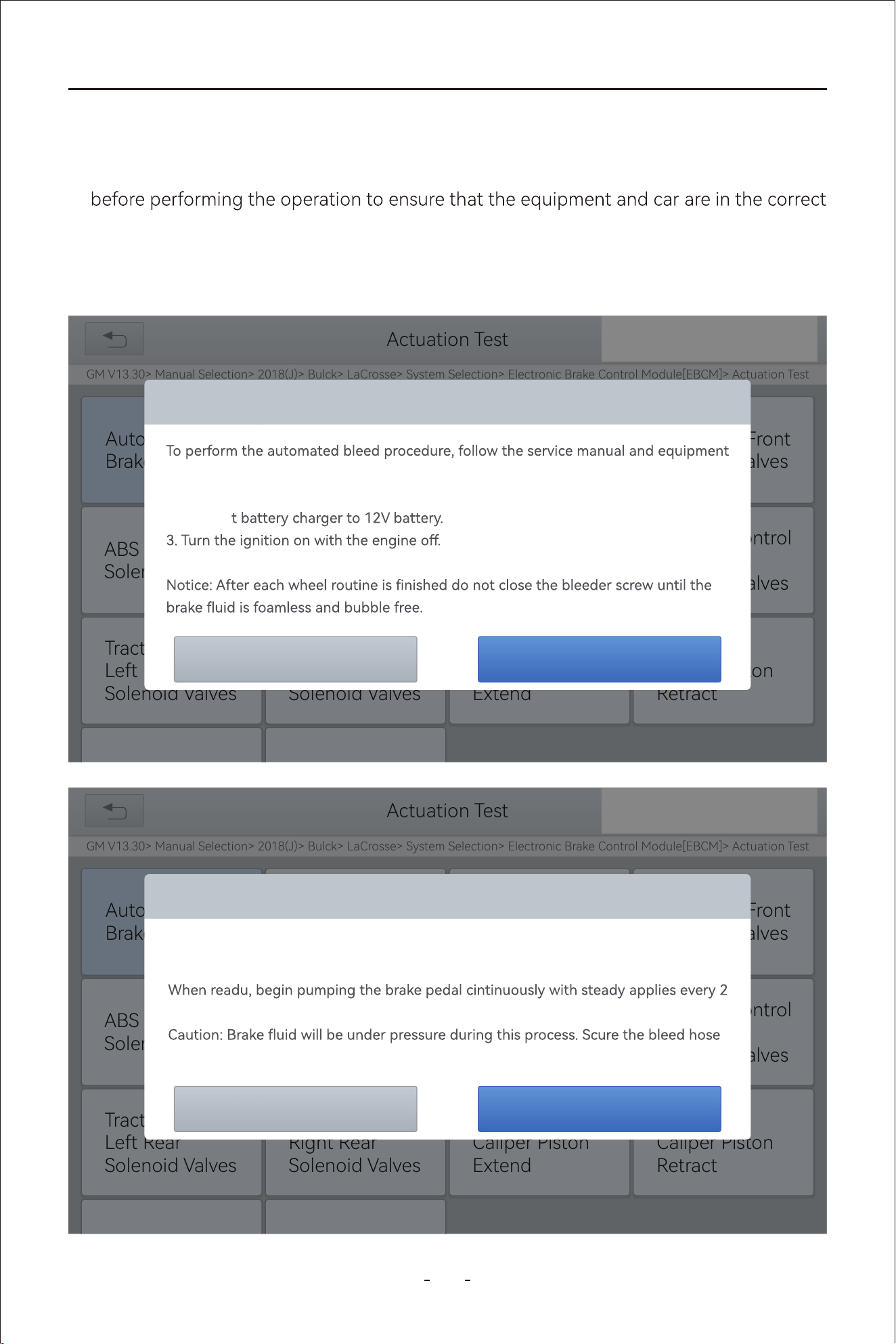
80
VD80 BT Diagnostic Tool
1. Read the operating instructions and precautions that appear on the screen carefully
condition
2. Attach bleeder bottle to the left rear bleeder screw.
3. Open the left rear bleeder screw.
The operation guidelines of the ABS Bleeding function are shown as below:
Actuation Test
GM V13.30> Manual Selection> 2018(J)> Bulck> LaCrosse> System Selection> Electronic Brake Control Module[EBCM]> Actuation Test
31%
SAE J1850 VPWSAE J1850 PWM
Automated
Brake Bleed
ABS Right Front
Solenoid Valves
ABS Left Rear
Solenoid Valves
Traction Control
Right Front
Solenoid Valves
Rear Brake
Caliper Piston
Retract
Rear Brake
Caliper Piston
Extend
Traction Control
Right Rear
Solenoid Valves
Traction Control
Left Rear
Solenoid Valves
HELPISO 15765-4
Automated Brake Bleed
OK
Cancel
manufacturer’s instructions.
1. Connect the required brake bleed equiment.
2. Connec
4. Place transmission in the park or neutral position.
Actuation Test
GM V13.30> Manual Selection> 2018(J)> Bulck> LaCrosse> System Selection> Electronic Brake Control Module[EBCM]> Actuation Test
31%
SAE J1850 VPWSAE J1850 PWM
Automated
Brake Bleed
ABS Right Front
Solenoid Valves
ABS Left Rear
Solenoid Valves
Traction Control
Right Front
Solenoid Valves
Rear Brake
Caliper Piston
Retract
Rear Brake
Caliper Piston
Extend
Traction Control
Right Rear
Solenoid Valves
Traction Control
Left Rear
Solenoid Valves
HELPISO 15765-4
Automated Brake Bleed
OK
Cancel
Attach blleder bottle to the left rear bleeder screw.
Open the left rear bleeder screw.
seconds during the entire bleed procedure.
and open bleeder screws slowly.
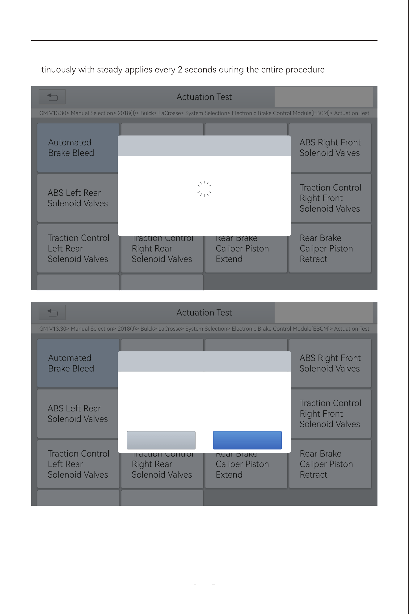
81
VD80 BT Diagnostic Tool
4. When ready, click "OK" to enter the bleed procedure, and pumping the brake pedal con-
5. Continue pumping the brake pedal, when air bubbles are no longer visible, select OK to
enter next bleed procedure for left front wheel
Actuation Test
GM V13.30> Manual Selection> 2018(J)> Bulck> LaCrosse> System Selection> Electronic Brake Control Module[EBCM]> Actuation Test
31%
SAE J1850 VPWSAE J1850 PWM
Automated
Brake Bleed
ABS Right Front
Solenoid Valves
ABS Left Rear
Solenoid Valves
Traction Control
Right Front
Solenoid Valves
Rear Brake
Caliper Piston
Retract
Rear Brake
Caliper Piston
Extend
Traction Control
Right Rear
Solenoid Valves
Traction Control
Left Rear
Solenoid Valves
HELPISO 15765-4
Automated Brake Bleed
The procedure is in progress, please wait 5s
Actuation Test
GM V13.30> Manual Selection> 2018(J)> Bulck> LaCrosse> System Selection> Electronic Brake Control Module[EBCM]> Actuation Test
31%
SAE J1850 VPWSAE J1850 PWM
Automated
Brake Bleed
ABS Right Front
Solenoid Valves
ABS Left Rear
Solenoid Valves
Traction Control
Right Front
Solenoid Valves
Rear Brake
Caliper Piston
Retract
Rear Brake
Caliper Piston
Extend
Traction Control
Right Rear
Solenoid Valves
Traction Control
Left Rear
Solenoid Valves
HELPISO 15765-4
Automated Brake Bleed
Continue Pumping the Brake Pedal.
When air bubbles are no longer visible, select[OK]
OK
Cancel
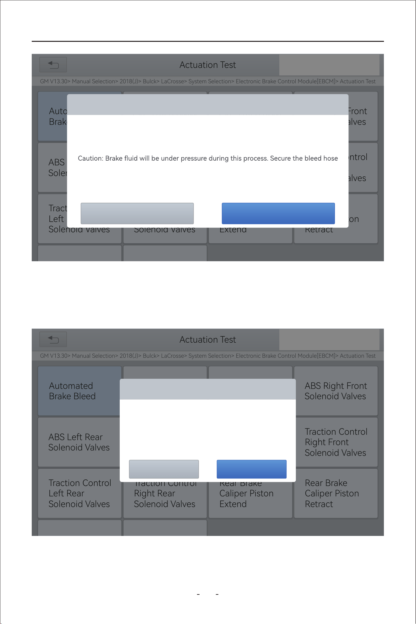
82
VD80 BT Diagnostic Tool
7. Stop pumping the brake pedal, and close the right rear bleeder screw
8. Click OK to complete the entire bleed procedure
6. Repeat the operation 3 times to complete the bleed procedure for the left front wheel,
right front wheel and right rear wheel in turn.
Actuation Test
GM V13.30> Manual Selection> 2018(J)> Bulck> LaCrosse> System Selection> Electronic Brake Control Module[EBCM]> Actuation Test
31%
SAE J1850 VPWSAE J1850 PWM
Automated
Brake Bleed
ABS Right Front
Solenoid Valves
ABS Left Rear
Solenoid Valves
Traction Control
Right Front
Solenoid Valves
Rear Brake
Caliper Piston
Retract
Rear Brake
Caliper Piston
Extend
Traction Control
Right Rear
Solenoid Valves
Traction Control
Left Rear
Solenoid Valves
HELPISO 15765-4
Automated Brake Bleed
OK
Cancel
Close left rear bleeder screw.
Attach bleeder bottle to the left front bleeder screw.
Open the left front bleeder screw.
and open the bleeder screw slowly.
Notice: Continue to pump brake pedal with steady applies throughout entire
procedure.
Actuation Test
GM V13.30> Manual Selection> 2018(J)> Bulck> LaCrosse> System Selection> Electronic Brake Control Module[EBCM]> Actuation Test
31%
SAE J1850 VPWSAE J1850 PWM
Automated
Brake Bleed
ABS Right Front
Solenoid Valves
ABS Left Rear
Solenoid Valves
Traction Control
Right Front
Solenoid Valves
Rear Brake
Caliper Piston
Retract
Rear Brake
Caliper Piston
Extend
Traction Control
Right Rear
Solenoid Valves
Traction Control
Left Rear
Solenoid Valves
HELPISO 15765-4
Automated Brake Bleed
Stop pumping the brake pedal.
Close the right rear bleeder screw.
OK
Cancel
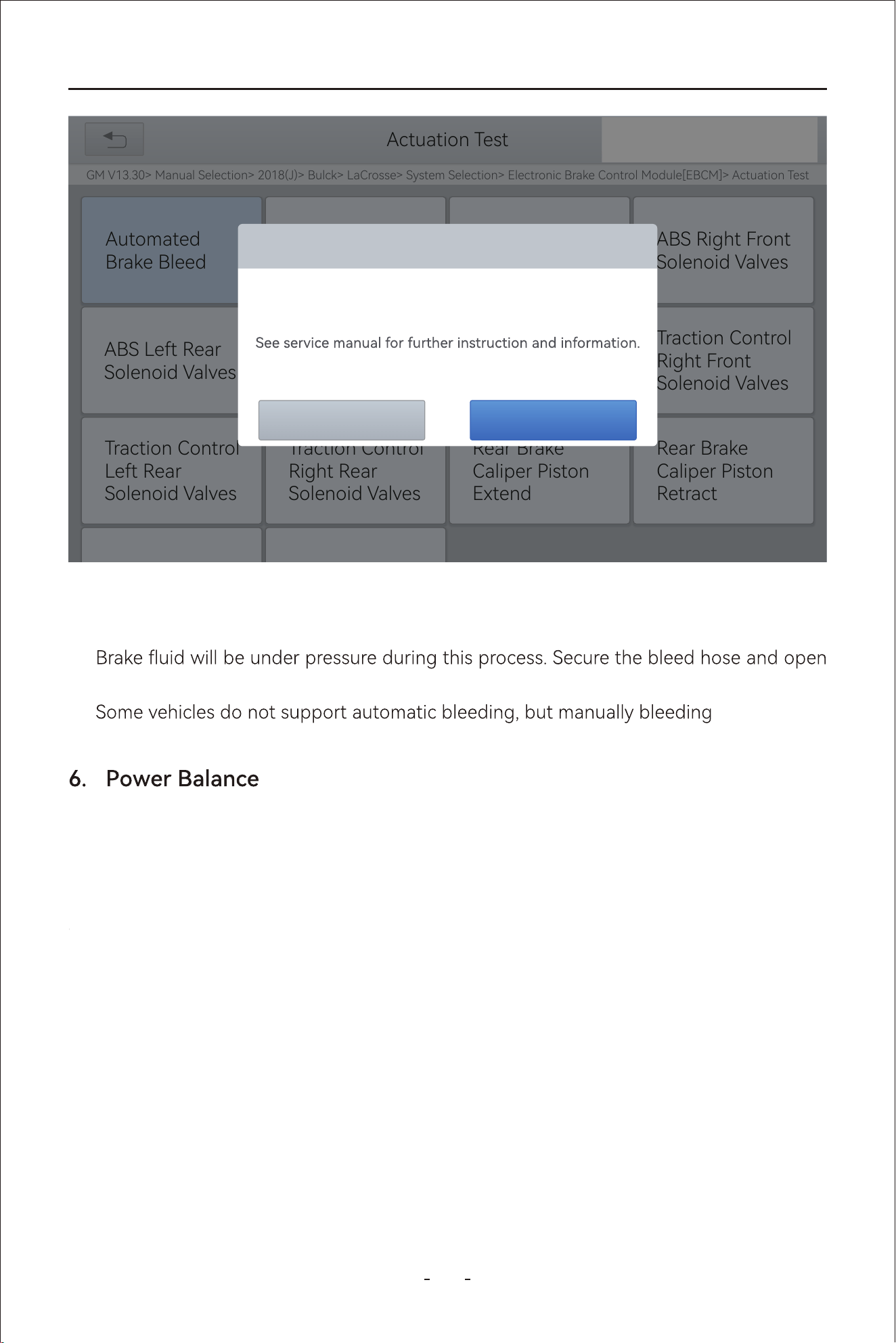
83
VD80 BT Diagnostic Tool
Caution
The ABS pump screw needs to be unscrewed●
●
bleeder screws slowly
●
8
This function is to shut down individual injector and monitor the power output drop by
RPM to determine the relative power contributed by each cylinder and decide which
cylinder malfunctions.
Or called Seat Congurations. This function is applied to match or congure the seats
with memo function that are replaced and repaired.
Actuation Test
GM V13.30> Manual Selection> 2018(J)> Bulck> LaCrosse> System Selection> Electronic Brake Control Module[EBCM]> Actuation Test
31%
SAE J1850 VPWSAE J1850 PWM
Automated
Brake Bleed
ABS Right Front
Solenoid Valves
ABS Left Rear
Solenoid Valves
Traction Control
Right Front
Solenoid Valves
Rear Brake
Caliper Piston
Retract
Rear Brake
Caliper Piston
Extend
Traction Control
Right Rear
Solenoid Valves
Traction Control
Left Rear
Solenoid Valves
HELPISO 15765-4
Automated Brake Bleed
Procedure Complete
OK
Cancel
6.9 Seat Calibration
84
VD80 BT Diagnostic Tool
0
This function works together with EEPROM adapter which is not included in this package to
read and write data into EEPROM. This function is used in Instrument Cluster function for
some vehicle models.
1
This function is to change the system language of the instrument cluster or control
console.
2
During shipment from the facto, a vehicle is put in a paially activate state called Trans-
po Mode to reducethe drain on the batte. And when it arrives at the dealership, this
function is applied to deactivate or disable the Transpo Mode.
3
This function is to reset the ECU software when fault occurs due to abnormal working tem-
perature or voltage change.
4
Also called Throttle Reset or Throttle Match. This function enables you to reset the throttle
actuators and the learned values stored on ECU to the default state. Doing so can accu-
rately control the actions of regulating throttle (or idle engine) to adjust the amount of air
intake.
5
This function is to reset the rain/light sensor after the replacement of the rain/light sensor
or the front windshield.
6
This function is to reset or relearn the air/fuel ratio parameters.
7
This function is used to check the voltage of individual batte pack.
18
This function can complete the self-learning of the gearbox and improve the shift quality,
when the gearbox is disassembled or repaired which may cause shifting delay or impact.
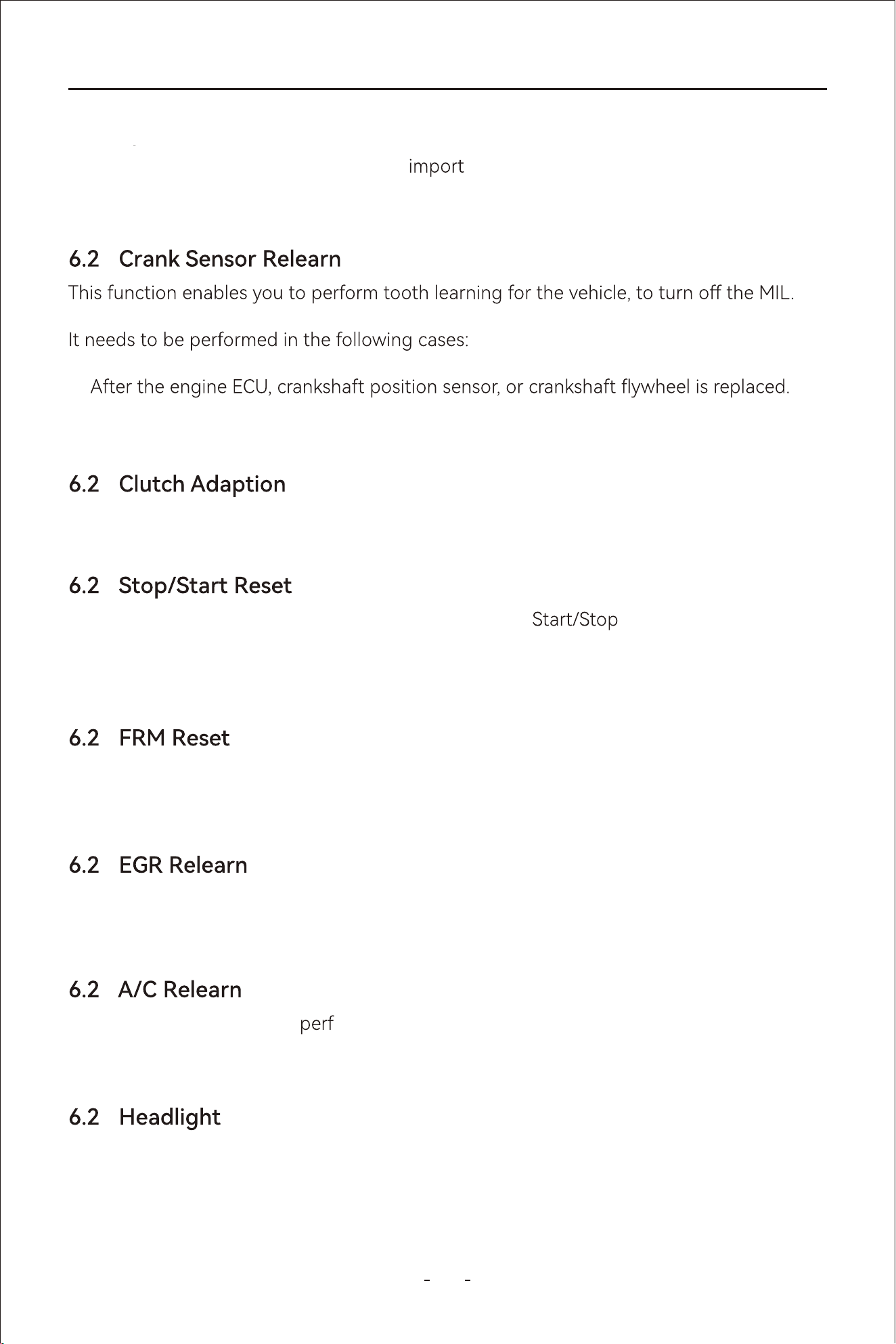
85
VD80 BT Diagnostic Tool
1
This function is to reset the clutch after the replacement of clutch or gear shifting motor.
2
This function is used to open or close the automatic function via setting the
hidden function in ECU (The precondition is vehicle equipped with hidden function and
hardware is in place).
3
This function is to reset the Footwell Room Module when unstable voltage triggered fault
and the doors, windows, headlight malfunctions.
4
Also called EGR Adaption. This function is used to learn the EGR (Exhaust Gas Re-Circula-
tion) valve after it is cleaned or replaced.
5
AC system relearn must be ormed when the vehicle AC ECU or actuator is replaced or
the ECU memo is lost.
6
Also called Headlight Adjustment, Headlight Matching or AFS Reset. This function can
initialize the adaptive headlight system. The headlight system can decide whether to auto-
matically turn on the headlights based on the ambient light intensity, monitor the vehicle’s
driving speed, body posture, etc., and adjust the headlight lighting angle.
1.
2. The DTC ‘tooth not learned’ is present.
9
This function is to remove speed limit for ed vehicle, vehicle for government agencies
or police.
0
6.19 Speed Limit
86
VD80 BT Diagnostic Tool
6.27 SRS
This function is to reset the acceleration sensor when it’s replaced or it’s providing wrong
data which is used for SRS system, anti-theft system or navigation system.
6.28 Windows Initialization
When
, and recover the
automatic ascending and descending function of power window.
6.29 VGT Relearn
Also called VGT Turbo Calibration. This function is used to calibrate the newly installed com-
T.
This is always done when the component has been detected as operating “out of range”.
6.30 Coolant Bleeding
Also called Electric Water Pump Activation. This function is used to activate the electric
water pump after it’s replaced.
6.31 Suspension
This function can adjust the vehicle body height sensor for level calibration after replacing
the vehicle height sensor or control module in the air suspension system, or when the vehi-
cle level is not correct.
6.32 Airbag Reset
This function is used to reset the airbag system, airbag warning light when airbag has been
replaced and clear crash data.
6.33 Tire Size Reset
This function is to reset the tire size when it’s replaced or upgraded.
Note:

87
VD80 BT Diagnostic Tool
6.34 AdBlue Reset
The AdBlue system consists of a tank, a pump and various sensors to monitor liquid level,
pressure and temperature. Whereas, AdBlue Reset is the process of resetting the AdBlue
system counters after relling the AdBlue tank.
In a diesel vehicle, we need to add AdBlue in addition to diesel. However, this AdBlue is not
not for combustion in the engine, but for treating the engine exhaust.
Insucient AdBlue in a diesel vehicle will cause the engine to fail to sta, and it is necess-
a to add AdBlue again and use the special function of the Diagnostic Tool to remove
the vehicle restrictions.
6.35 ECU Conguration
Due to the dierence between high-end and low-end vehicles, many low-end models have
hidden high-end functions. Releasing these hidden functions can bring convenience to car
owners, but ashing hidden functions involves programming and coding knowledge, and
sometimes you have to enter the channel number, etc., so you must be familiar with the
various congurations of the car to accurately turn on the required functions.
Use the Diagnostic Tool to que the hidden functions that can be ashed on the vehicle
and ash them. Common hidden functions include: passive tire pressure monitoring, one-
button car search, automatic locking, speeding reminder, seat belt reminder function, etc.
6.36 Sunroof Initialization
6.37 Camshaft Learning
6.38 TCM Oil Reset
When the vehicle batte is disconnected, the windows may not work right. This function is
used to peorm sunroof matching to recover the ECU initial memo, and recover the auto-
matic ascending and descending function of power window.
This function refers to the process of calibrating the engine control unit(ECU) to match the
actual camshaft position with the expected position. This is crucial for ensuring proper
engine timing, as the camshaft dictates when the valves open and close, which directly
aects fuel injection and ignition.
The Diagnostic Tool can be used to reset the TCM oil life system, which calculates the opti-
mum oil life change inteal based on the vehicle’s driving conditions and climate. The oil
life reminder must be reset each time the oil is changed so that the system can calculate
when the next oil change is due.
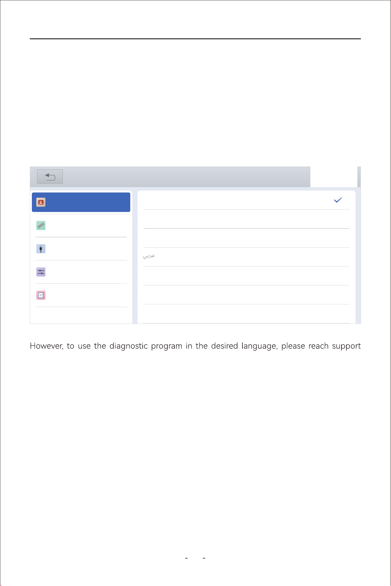
88
VD80 BT Diagnostic Tool
team and provide the S/N of the Diagnostic Tool to authorize the desired language soft-
ware program. When it’s authorized, you need to download all software programs for the
new language and set the language of the android tablet as indicated in the paragraph
above.
This setting provides 3(three) sets of units to measure various sensor values.
Metric Units: Centimeters, kilometers, grams, kilo,℃,litres, pa, kpa
Imperial Units: Inch, foot, yard, oz, lb, ℉,PSI, mile, galon
US Units: Inch, foot, yard, oz, lb, ℉, PSI, mil, mile
7.2 Unit
7. Settings
This chapter describes the settings diagnostic software or the tablet including language
of the tablet, units used in the diagnostic program, USB po mode setting, and etc.
7.1 Language
Go to “Settings”- “Language” to change the language of the android tablet into the
language you want to use.
31%
Settings
Language
Unit
USB setting
Sound & Display
About
English
简体中文
繁體中文
Deutsch
ελληνικά
Español
Français
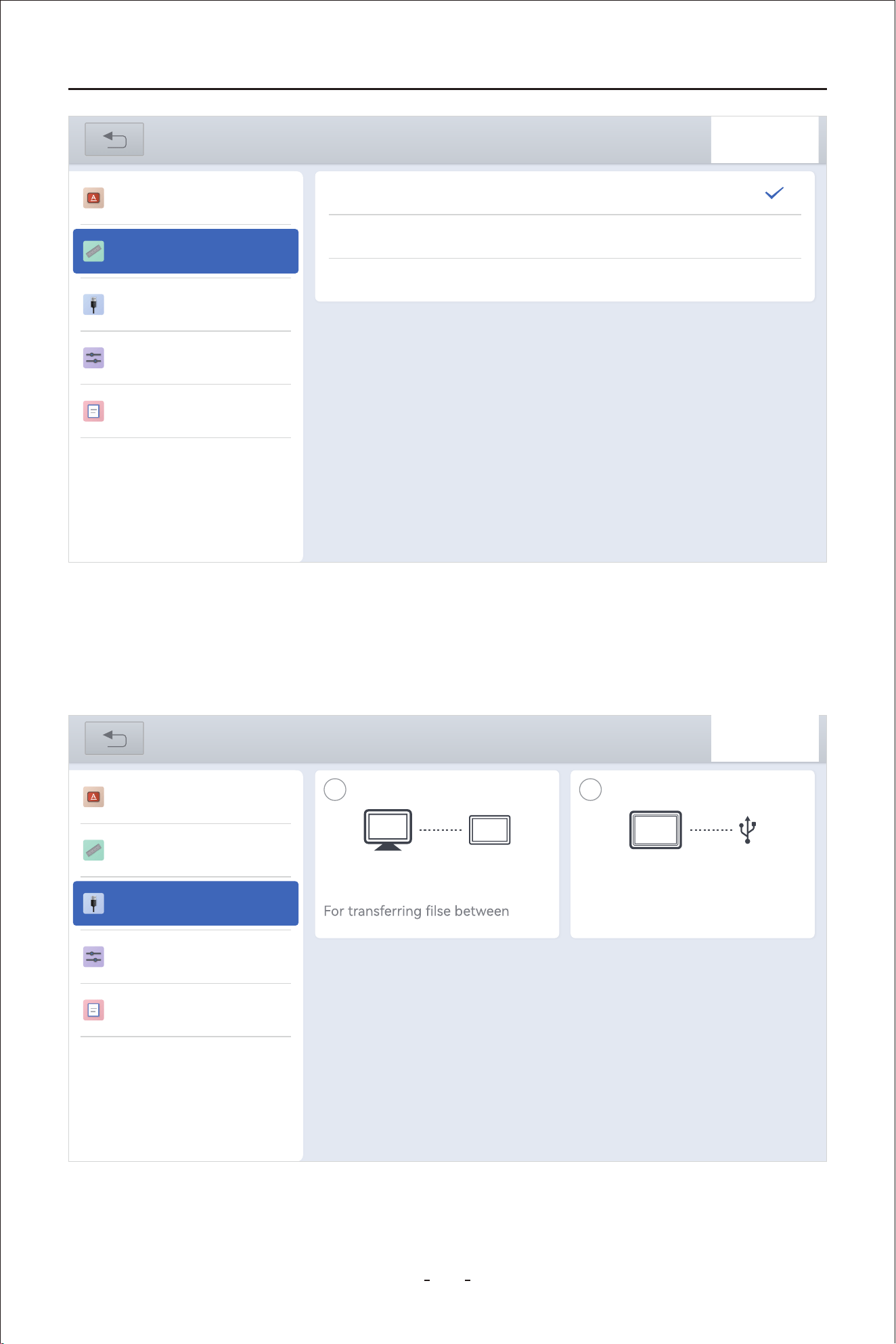
89
VD80 BT Diagnostic Tool
This section enables you to set the USB Type-C mode between “Data Transfer Mode” and
“Expansion Mode”.
7.3 USB Setting
Data Transfer Mode: To transfer data between the android tablet and a PC.
Expansion Mode: To work with extension accessories like EEPROM adapter.
31%
Settings
Language
USB setting
Sound & Display
About
Metric Units
Imperial Units
U.S. Units
Unit
31%
Settings
Language
Unit
USB setting
Sound & Display
About
Data transfer mode
device and PC
Expansion mode
For connecting to expansions or
accessories
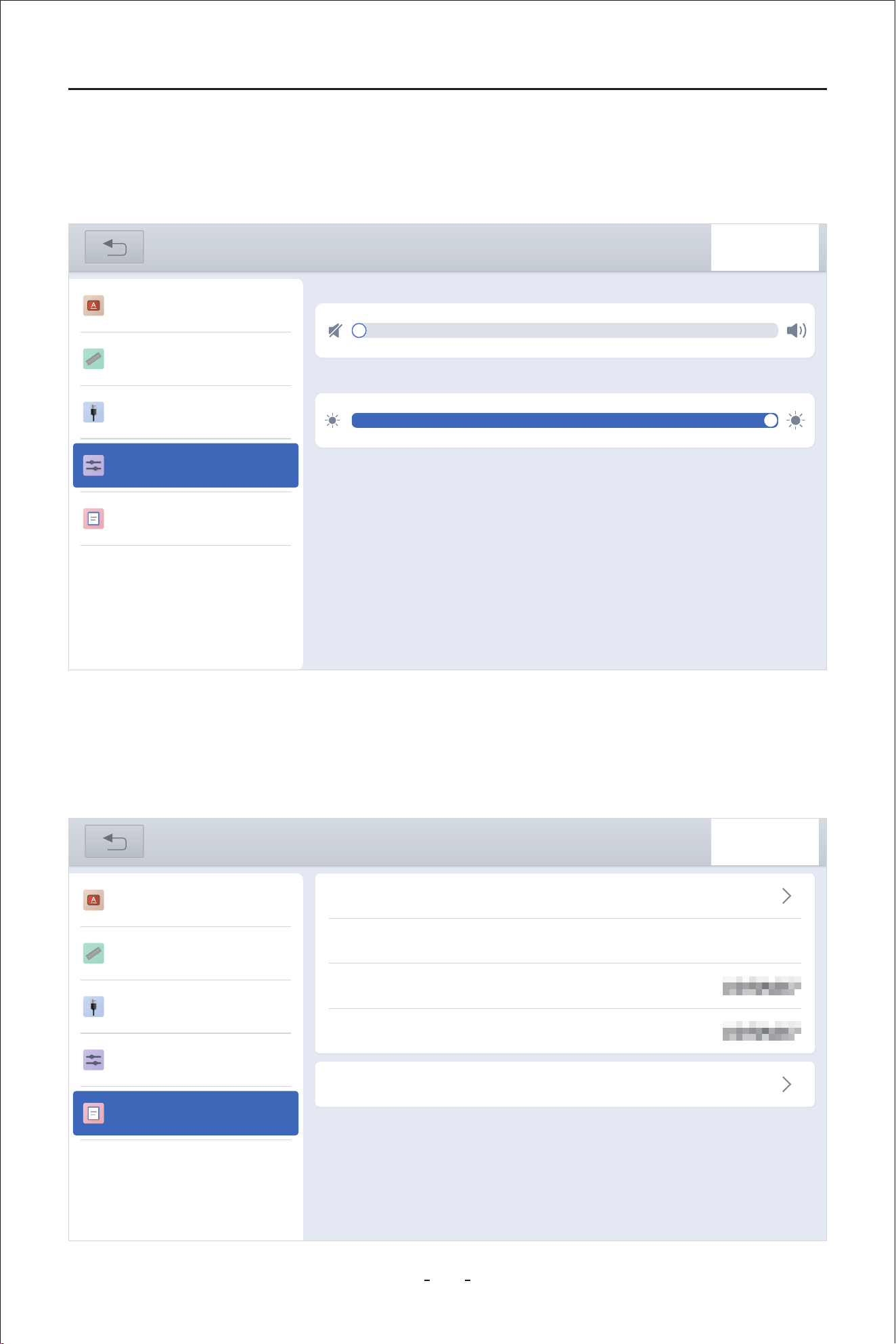
90
VD80 BT Diagnostic Tool
This section enable you to set the sound level of the built-in speaker and the brightness of
the screen.
7.4 Sound & Display
This section describes the app version, OS version, S/N of the Diagnostic Tool, VCI name,
and set the O.S.
7.5 About
31%
Settings
Language
Unit
USB setting
Sound & Display
About
Adjust volume
Brightness level
31%
Settings
Language
Unit
USB setting
Sound & Display
About
APP
OS
SN
VCI
V5.5.6_10.09
PAD01_V3.0.5_20240123
VD80 BT-VD70SVD7
VD80 BT-VD70SVD7
OS Settimgs
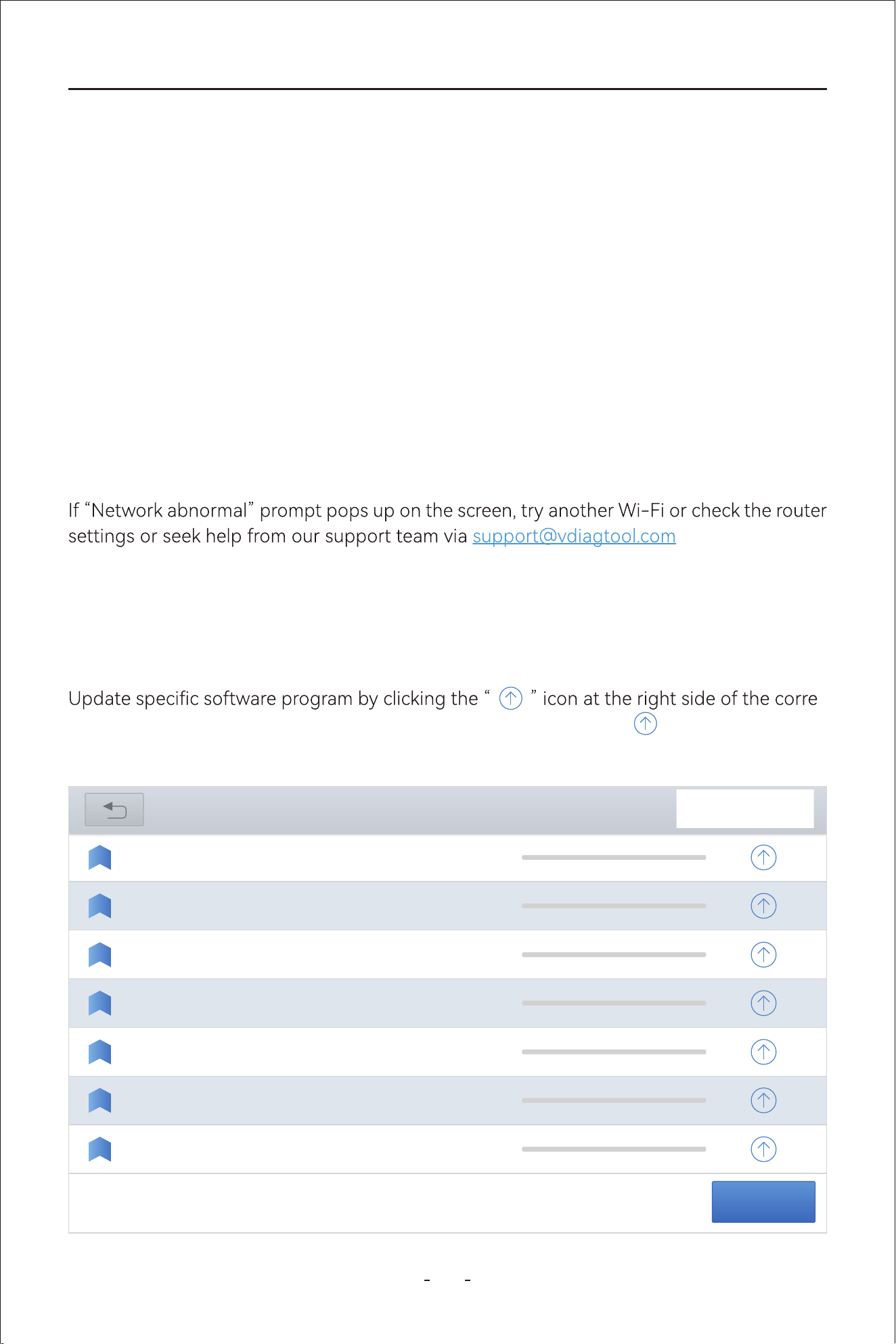
91
VD80 BT Diagnostic Tool
This chapter describes how the software subscription works and the basic software update
operations.
You can update the software programs while it’s connected to a Wi-Fi or mobile phone
hotspot. Mobile phone hotspot is recommended as it has less network provider restrictions
when home Wi-Fi fails.
Option 1: Update All Software Programs
Update all by clicking “Update All” at the bottom right of the update menu
Option 2: Update Individual Software Program
-
sponding software program. If the update is interrupted, click the “ ” icon again to pro-
ceed.
To update the software programs, you have 2(two) options:
.
8. Software Updates
The subscription is a yearly fee for all makes and models that it’s compatible with, not
by individual model or by individual function.
●
When the subscription expires, you have the choice to whether renew it or not, whether
to renew it now or skip the years that you are not ready to update. If you don’t renew
the subscription, the old software programs stay on the Diagnostic Tool, just not being
able to update to the date.
●
DIAGNOSIS--FIAT V11.91
2024-03-13
14:19:19
DIAGNOSIS--MG
V10.90
2024-03-27
17:55:58
DIAGNOSIS--PROTON V8.80
2024-03-26
14:48:56
DIAGNOSIS--JEEP
V9.91
2024-03-29
14:42:03
V19.03
2024-03-22
14:53:331
DIAGNOSIS--HONDA
V12.47
2024-03-16
09:05:18
1
2
3
4
5
6
7
V5.0
2025-04-28
03:55:11
updates
Update All
DIAGNOSIS--
TRANSPORTER
DIAGNOSIS--NISSAN
PIN DATA
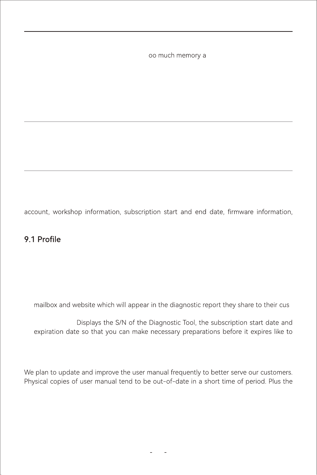
92
VD80 BT Diagnostic Tool
Delete Software Program:
When the diagnostic tablet has taken up t
nd become slow, the solution
is to delete the software programs you rarely use to free up some space.
Delete diagnostic software program:
To delete rarely used diagnostic software program, click “Manual Diagnosis”- Select
Region- Press and hold the vehicle maker icon that you rarely use to activate the job menu-
Click “Delete” to delete the software program.
This chapter describes “More” options on the main diagnostic menu including your user
endoscope and user manual.
9. More
Account Information- Allows you to set the user name, product registration mailbox,
reset password and log out the account so that you can log in with another account.
●
Workshop- Allows technician or workshop to set the workshop name, address, phone,
-
tomers.
●
Subscription-
update all software programs to the latest.
●
This section allows you to set the user account, workshop and check subscription informa-
tion.
9.2 User Manual
IMPORTANT:
Do NOT delete the software programs if the subscription is near. It’s recommended to
download all software programs you deleted before the subscription expires.
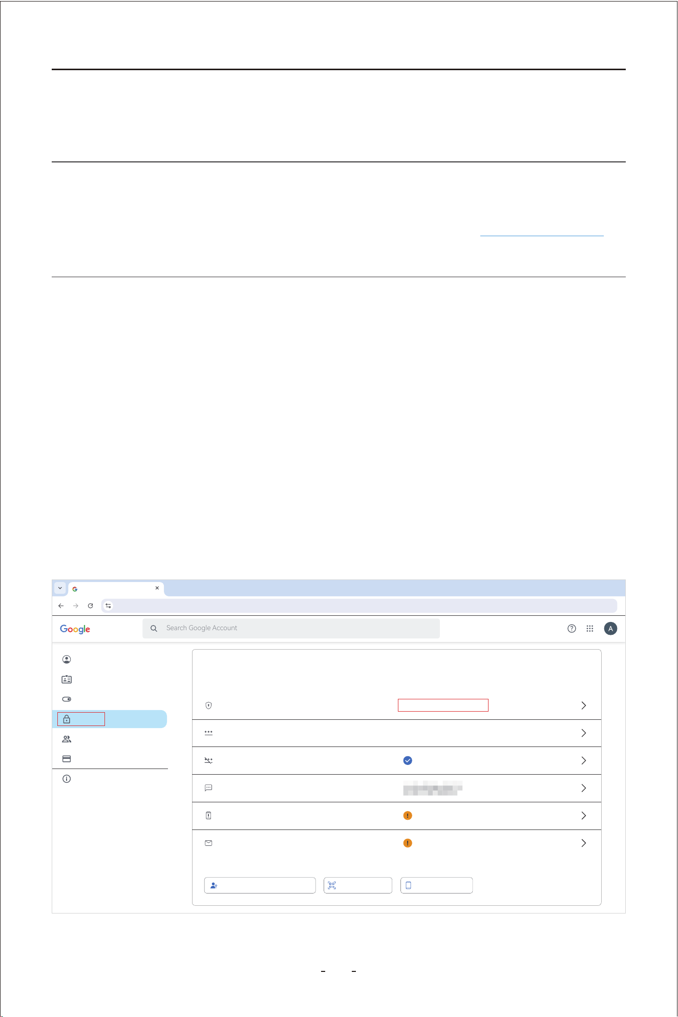
93
VD80 BT Diagnostic Tool
User Manual in PDF le version adds the option to search the specic information from the
substantial content of this manual. Hence, we decide to add this section to update the User
Manual from time to time.
Note:
We update and upload the latest User Manual to our website more frequently than we
update the App of the Diagnostic Tool. Please refer to our website www.vdiagtool.com for
the latest possible version of User Manual.
Step 1: Log into your Google Account and click “Security”- “2-Step Verication”- Click “Get
Staed” to set up 2-Step Verication- Set up a backup phone and turn on 2-Step Verica-
tion.
This functions allow you check the compatibility between your vehicle and the Diagnostic
Tool. However, this is for reference only. For better compatibility conrm, please provide
your device S/N, your vehicle VIN and the desired functions to our tech suppo team at
suppo@vdiagtool.com.
10.1 Email Settings
9.3 Vehicle Coverage
10. Other Settings
Account
Search Google Account
Security
myaccount.google.com/security?rapt=AEjHL4NancjUYOQj-jo64Qkxylm3IpU_QpGOk4BaCH5_zzlg9xP4jVVczKZ-pz7OnFq6o5ZSBCS3C2tmUI2PT5_wbzS0gIRCjAVKsxCvr5L5BiRdWCe
Home
Personal info
Data & privacy
Security
People & sharing
Paymentss & subscriptions
About
Passkeys and security keys Authenticator Google prompt
2-Step Verication
How you sign in to Google
Make sure you can always access your Google Account by keeping this information up to date
You can add more sign-in options
Password
Skip password when possible
2-Step Verication phones
Recove phone
Recove email
2-Step Verication is o
Last changed 4�00PM
On
Add a mobile phone number
Add an email address
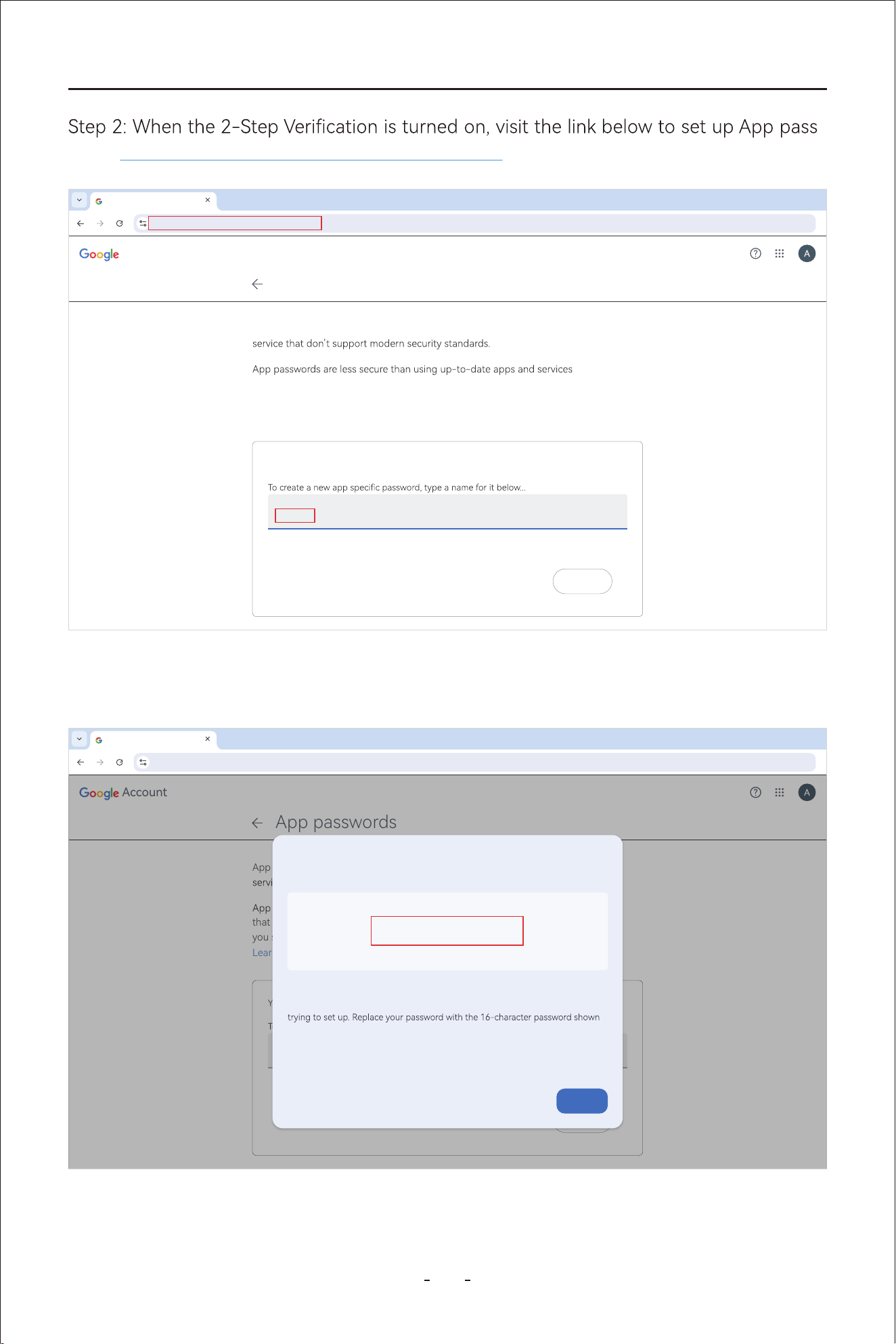
94
VD80 BT Diagnostic Tool
-
word. https://myaccount.google.com/apppasswords
Account
App passwords
https://myaccount.google.com/apppasswords
App passwords help you sign into your Google Account on older apps and
that use modern security standards. Before you create an app password,
you should check to see if your app needs this in order to sign in.
Learn more
You don’t have any app passwords.
VD80 BT
App name
Create
App passwords
Step 3: Set up a custom app name(VD80 BT as in example above), to generate a password
(16 letters) to log into this custom app. Copy and save this password.
Account
App passwords
https://myaccount.google.com/apppasswords
App passwords help you sign into your Google Account on older apps and
that use modern security standards. Before you create an app password,
you should check to see if your app needs this in order to sign in.
Learn more
You don’t have any app passwords.
App name
Create
App passwords
Generated app password
Your app password for your device
How to use it
Go to the settings for your Google Account in the application or device you are
above.
Just like your normal password, this app password grants complete access to
your Google Account. You won’t need to remember it, so don’t write it down or
share it with anyone.
fnsa nggb atnx pmxd
Done
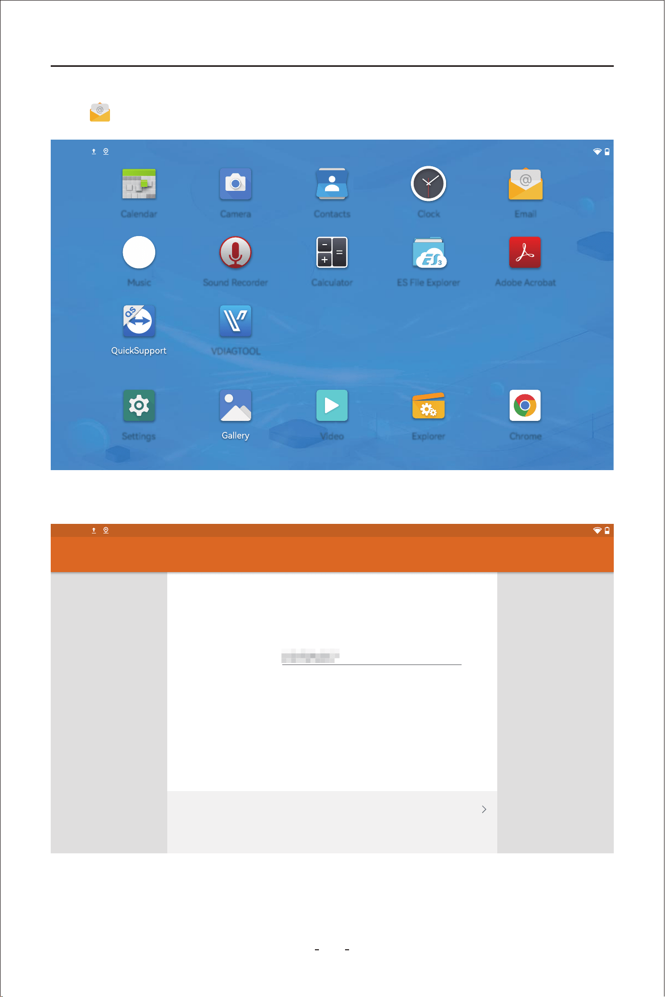
95
VD80 BT Diagnostic Tool
Step 4: Go to your Diagnostic Tool, swipe up to bring up the hidden toolbar menu and click
the “ ” icon to add a new G-mail account.
Step 5: Input your G-mail account and the app password(16 letters) and click “NEXT”
Email account
You can set up your account in just a few steps.
Email address
MANUAL SETPUP NEXT
@gmail.com
Account setup
2:40PM
2:40PM
EmailCalendar Camera Contacts Clock
Music Sound Recorder
VDIAGTOOL
Calculator ES File Explorer Adobe Acrobat
Settings Video Explorer Chrome
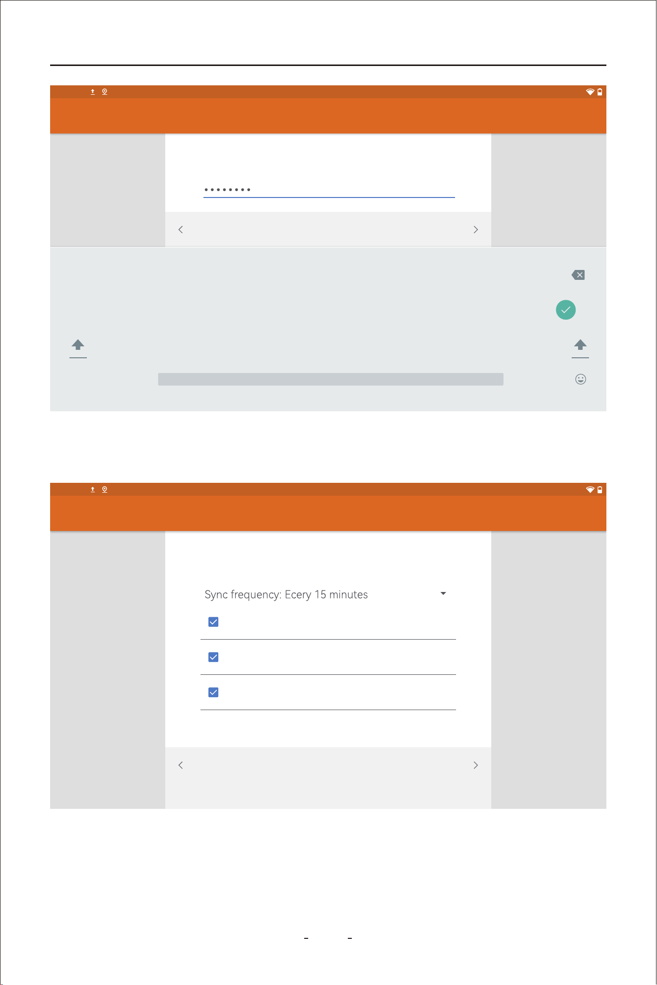
VD80 BT Diagnostic Tool
Step 6: Set the sync frequency and click “NEXT” until it displays “Your account is set up and
emails are on their way”.
Account setup
2:40PM
Sign in
NEXTPREVIOUS
?123
, .
q
1
w
2
e
3
r
4
t
5
y
6
u
7
i
8
o
9
p
0
z x c v b n m ! ?
a s d f g h j k l
Account setup
2:40PM
NEXTPREVIOUS
Account optioons
Notify me when emails arrives
Sync emails from this account
Automatically download attachments when
connected to Wi-Fi
96
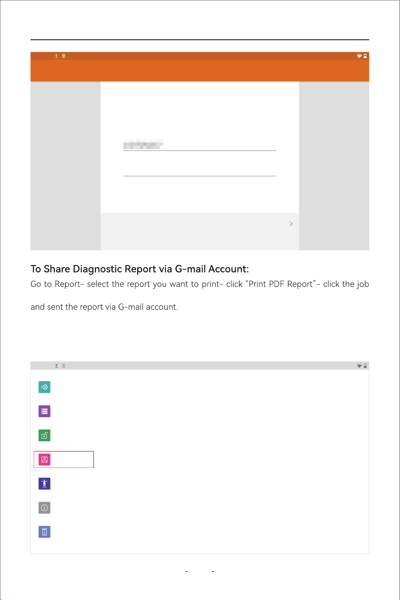
VD80 BT Diagnostic Tool
Step 1: Swipe up the hidden toolbar menu and click “Accounts”.
10.2 Delete Email Account
menu icon on the top right corner- Click “Share”- “Email” to go to Email composing page
NEXT
Account setup
2:40PM
Your account is set up and
emails are on their way!
Give this account a name (optional)
Your name (displayed on outgoing messages)
@gmail.com
2:40PM
Sound
Volume, Do Not Disturb
Storage
37% used - 40.28 GB free
Security
Screen lock
Accounts
Personal (IMAP)
Accessibility
Screen readers, display, interaction controls
System
Languages, gestures, time, backup
About tablet
VD80 BT
97
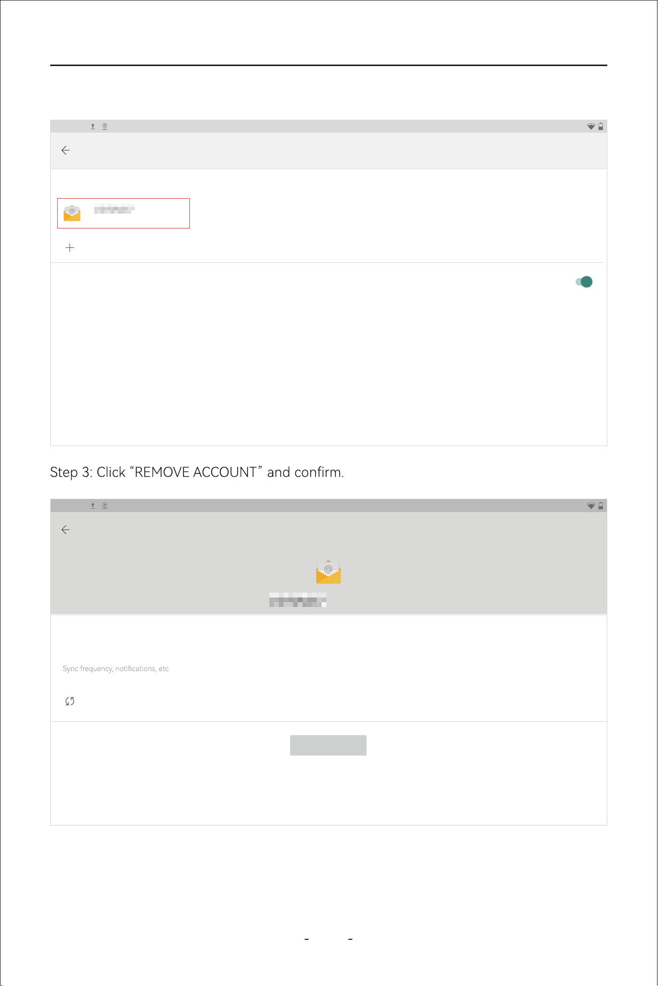
VD80 BT Diagnostic Tool
Step 2: Select the G-mail account you added.
2:40PM
Accounts
ACCOUNTS F OR OWNER
@gmail.com
Add account
Personal (IMAP)
Automatically sync data
Let apps refresh data automatically
2:40PM
Personal (IMAP)
@gmail.com
Account settings
Account sunc
Sync on for all items
REMOVE ACCOUNT
98
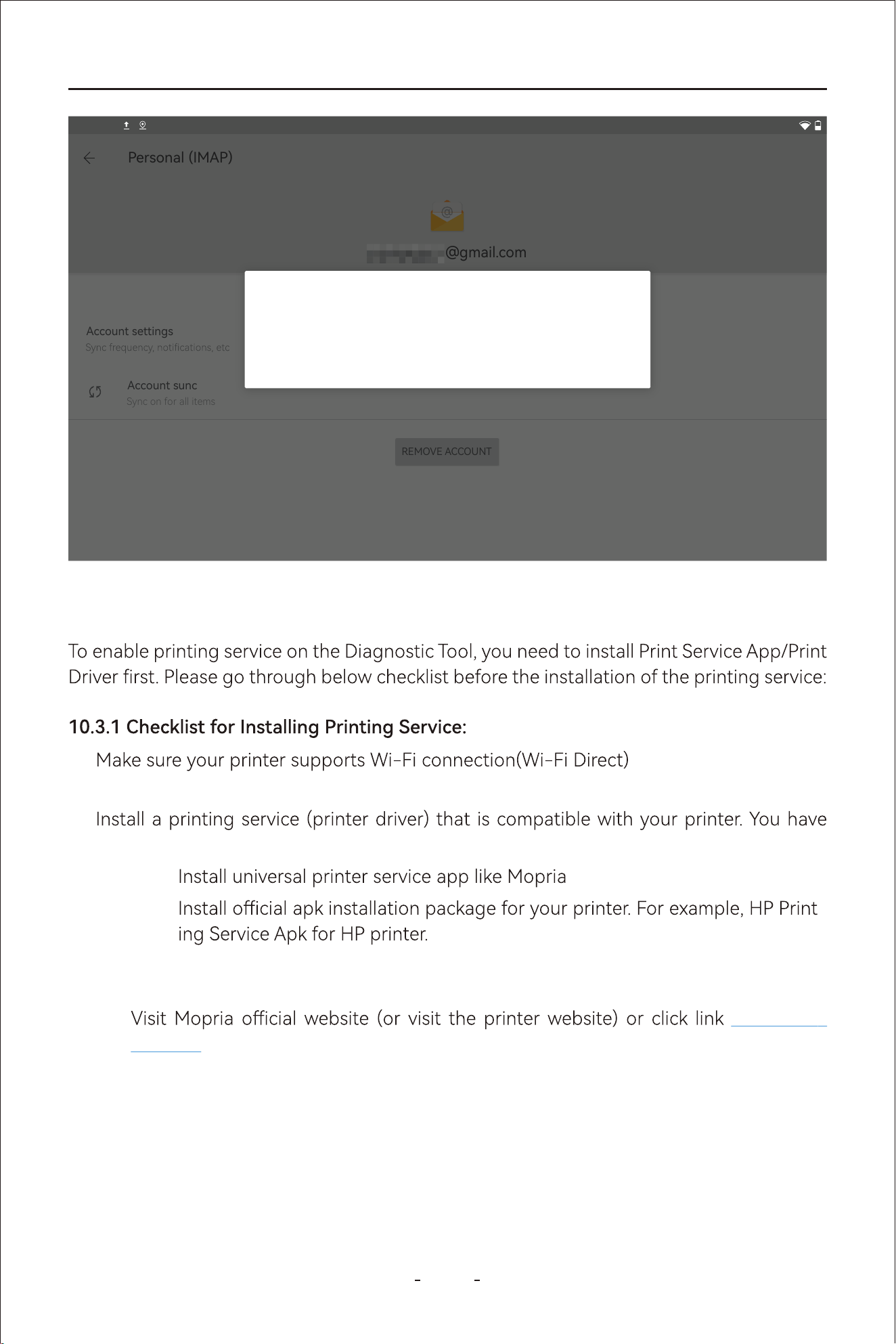
99
VD80 BT Diagnostic Tool
10.3 Printing Settings
●
10.3.2 Download the Corresponding APK File
https://mo-
pria.org/on your PC or laptop.
Step 1:
Click Print- Print from Android- Direct DownloadStep 2:
Check the brand, model of your printer●
two options:
Option 1:
Option 2: -
●
Personal (IMAP)
@gmail.com
Account settings
Account sunc
Sync on for all items
REMOVE ACCOUNT
2:40PM
Remove account?
Removing this account will delete all of its messages,contacts, and
other data from the tablet!
CANCEL REMOVE ACCOUNT
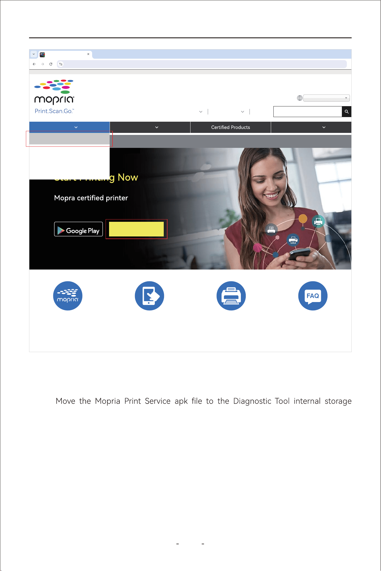
100
VD80 BT Diagnostic Tool
Connect the Diagnostic Tool to your PC or laptop through USB Type-C cable
attached and enable data transfer by swiping down from the upper left/right corner
on the Diagnostic Tool.
Step 3:
through Path: VD80 BT-Internal Shared Storage- Download.
Step 4:
Disconnect the Diagnostic Tool from the PC or laptop and go to ES File Explorer-
Diagnostic Tool.
Step 5:
Print From Android
https://mopria.org/
Print Scan Resources
About Us Membership Blog
Search...
English (US)
GET IN ON
Direct Download
Connect and print to any
without additional set-up.
Print From Android
Print With Windows
Print For Business
Print From Amazon Fire
What is Mopria Print? Get the Mopria Print
APP
How to Print Read FAQ
Local- Home - Download to locate the apk le and click it to install on the Diagno-
sitc Tool

101
VD80 BT Diagnostic Tool
Go to Settings- Connected Devices- Connection Preferences- Printing- Mopria
printer control panel.
Step 6:
2:40PM
Developed by the
Mopria Alliance
at your side
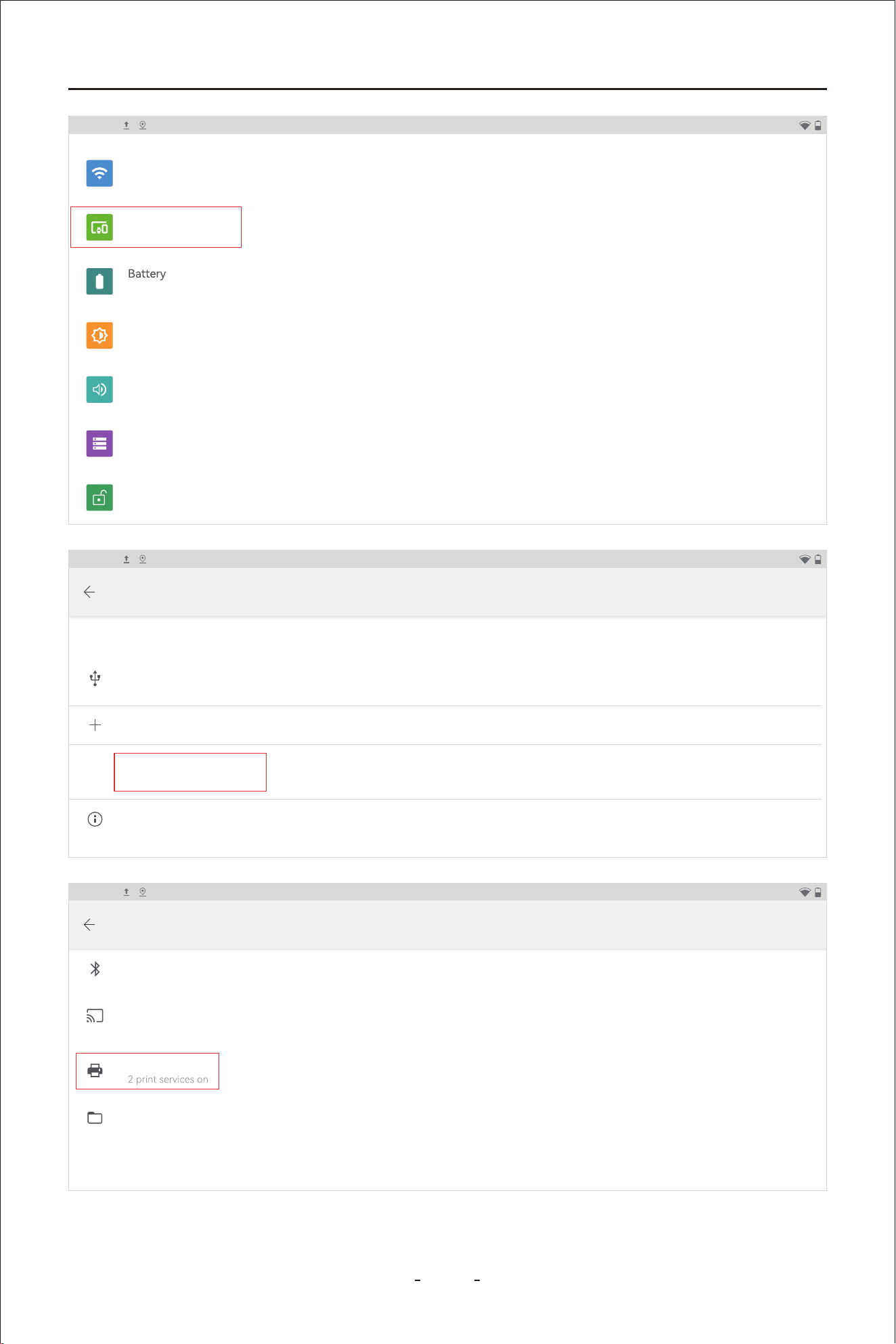
102
VD80 BT Diagnostic Tool
2:40PM
Network & internet
Wi-Fi, data usage, and hotspot
Connected devices
Bluetooth, printing
0% - charging
Display
Wallpaper, sleep, font size
Sound
Volume, Do Not Disturb
Storage
37% used - 40.28 GB free
Security
Screen lock
2:40PM
Connected devices
CURRENTLY CONNECT ED
Pair new device
Connection preferences
Bluetooth,printing
USB
Charging this device
Visble as “VD80 BT” to other devices
2:40PM
Connection preferences
Bluetooth
Cast
Not connected
Files received via Bluetooth
Printing
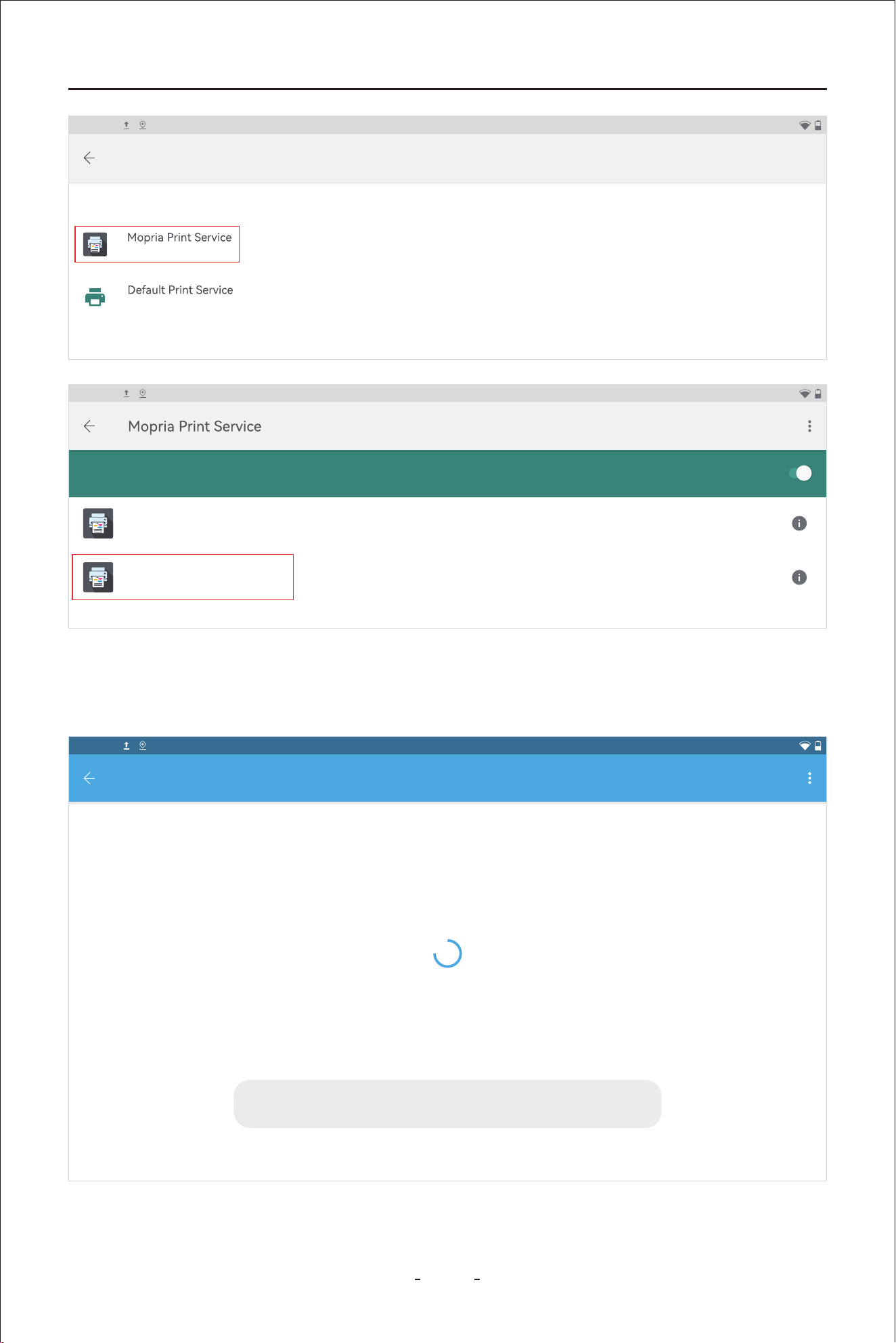
103
VD80 BT Diagnostic Tool
2:40PM
Printing
PRINT SERVICES
On
On
PRINT SERVICES
DIRECT-26-HP 2606 Laser Jet Tank
aa:3b:76983d:26
DIRECT-ce-HP M233 Laser Jet
be:f4:d4408:eb:ce
On
2:40PM
You may need to accept the connection to the printer on the printer front
panel.
2:40PM
Accounts
You may need to accept the connection to DIRECT-ce-HP M233 Laser Jet on its front
panel.
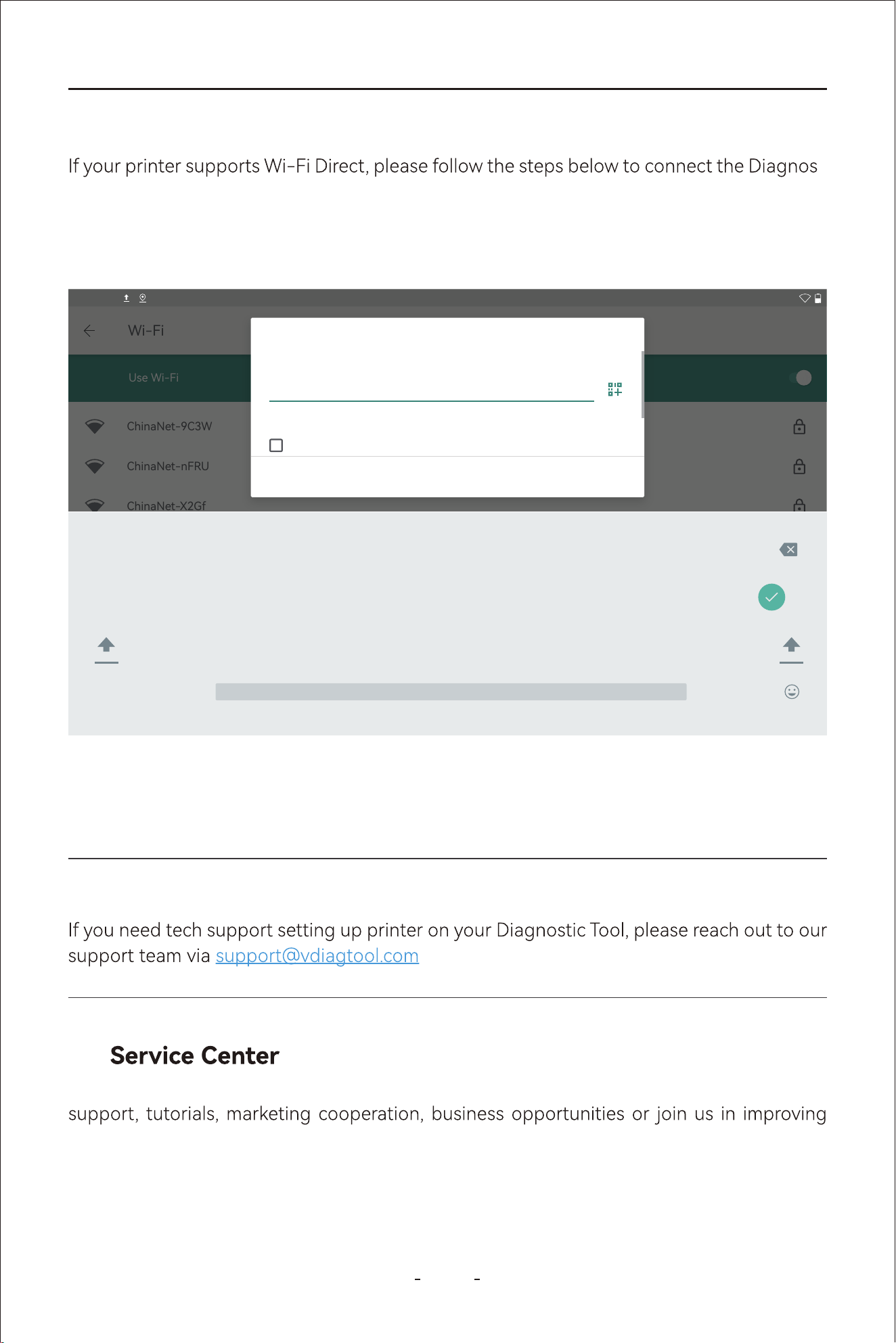
104
VD80 BT Diagnostic Tool
-
tic Tool to the printer directly:
10.4 Printer with WIFI Direct
Step 1: Swipe up the hidden toolbar menu and click “Settings”.
Step 2: Click Network & internet- Wi-Fi and click the printer Wi-Fi.
PRINT SERVICES
Use Wi-Fi
Wi-Fi
ChinaNet-9C3W
ChinaNet-nFRU
ChinaNet-X2Gf
?123
, .
q
1
w
2
e
3
r
4
t
5
y
6
u
7
i
8
o
9
p
0
z x c v b n m ! ?
a s d f g h j k l
2:40PM
DIRECT-ce-HP M233 Laser Jet
Password
Show assword
CANCEL CONNECT
Step 3: Check the SSID and password on the printer front panel and use it for Wi-Fi connec-
tion. If your printer does not come with front panel, print the printer information page on a
piece of paper and use it for Wi-Fi connection.
Note:
and provide us with your printer name, model.
This chapter displays the various ways that you can reach out to us for warranty claims, tech
the Diagnostic Tool you own and etc.
11.
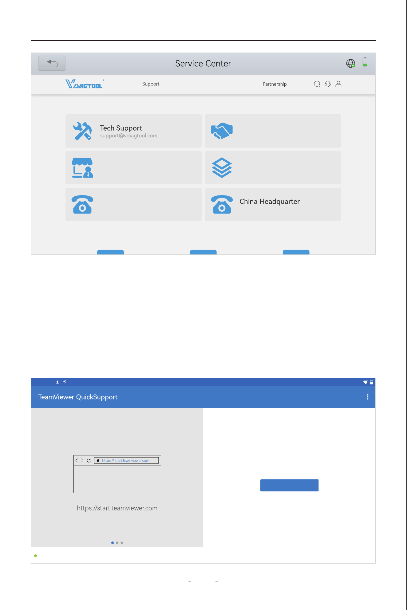
105
VD80 BT Diagnostic Tool
This function enable you to seek remote assistance from our tech team to control the Diag-
nostic Tool for operations that you are not familiar with.
Make sure the Diagnostic Tool is connected to Wi-Fi, then click “Remote Control” icon to
run the TeamViewer and wait until it shows “Ready to connect(secure connection)” at the
bottom left. Write down the TeamViewer ID which is at the center right of the screen and
schedule a remote assistance with us in advance.
11.1 Remote Control
31%
Marketing Cooperations
marketing@vdiagtool.com
Become Our Dealer
sales@vdiagtool.com
Help Us make Better Products
inventers@vdiagtool.com
United States
1-213-355-7171 +86-0755-86266490
Contact
Social Media
Home
Products
Where to Buy
About Us
How to connect to this device
On any other device, go to
2:40PM
Your ID
1 713 676 353
SEND MY ID...
Ready to connect (secure connection)
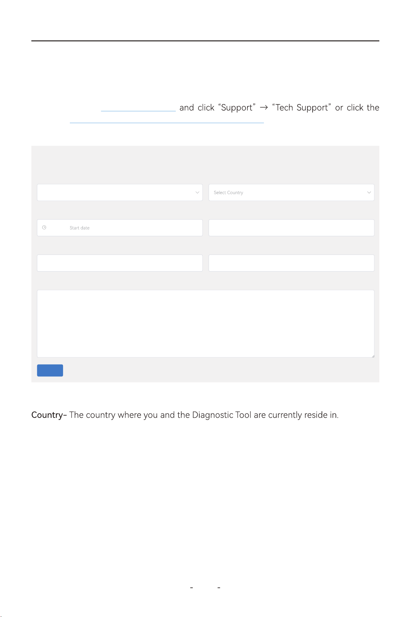
106
VD80 BT Diagnostic Tool
This section describes the procedure to schedule a remote assistance with us on our web-
site.
Region- The region where you and the Diagnostic Tool are currently located.
Serial Number- Serial Number of the Diagnostic Tool.
Remote ID- TeamViewer ID.
Phone- Phone number or mobile phone number through which our tech can contact you
for steps that requires your operation of the Diagnostic Tool or the vehicle during the
remote assistance session.
Problem Description- Describe the problem with the Diagnostic Tool or the vehicle why you
need the remote assistance session so that our tech can be prepared with the information
or tools before it. Useful information also can include your instant messengers.
Appointment Time Period- The time of period you are ready for remote assistance.
Visit our website www.vdiagtool.com
direct url https://www.vdiagtool.com/suppo/tech-suppo and ll out the “Remote App-
ointment” form below:
11.2 Schedule a Remote Control
Region*
Select Regionn
County*
Appointment time period* Serial Number*
Please Write Serial Number
Remote ID*
Please Write Remote ID
Phone
Please Write Your Phone Number
Problem Description*
Problem Description
End dateTo
Submit
Remote appointment
107
VD80 BT Diagnostic Tool
IMPORTANT:
-
So please make sure your Diagnostic Tool is connected to Wi-Fi for over 15 minutes and
provide the S/N with the form above so that our tech could locate the data logging from
For software issues like vehicle communication issue, function failed issue, and etc, data
11.3 Data Logging
whether or not a remote assistance session is to be scheduled.
11.4 App Logging
This section describes how to access our FAQ database on our website. Visit www.vdiag-
tool.com https://www.vdiag-
tool.com/suppo/faqs.
11.6 FAQ Database
To access our training videos, please visit our website www.vdiagtool.com and click “Sup-
https://www.vdiagtool.com/sup-
po/training-center.
11.7 Training Center
This section describes the programs we have for our customers.
11.8 User Programs
108
VD80 BT Diagnostic Tool
Whether you represent a company, school, government agency, or NGOs and you want to
buy in bulk, reach us through this program and get a bulk discount.
11.9 Corporate Purchase
Whether you are a professional automotive technician or DIY mechanic that have the
testers before they hit market, or inventers to build with us the product you like. Even if you
are a foreign language genius that can help us improve the User Manual in other languag-
es, you are welcome to reach us through this program.
11.10 Inventers and Testers Program
-
teurs that love to post content on social media platforms to help the community on how
11.11 U-Fluncer Program
If you liked our product and are interested to make a living selling it, reach us through this
program.
11.12 Become a Distributor

109
VD80 BT Diagnostic Tool
12. Warranty
This warranty is expressly limited to buyer who purchase VDIAGTOOL VD80 BT product for
VDIAGTOOL VD80 BT is warranted against defects in materials and workmanship for two
that has been abused, altered, used for a purpose other than for which it was intended, or
years (24 months) from date of delive to the buyer. This warranty does not cover any pa
used in a manner inconsistent with instructions regarding use. The exclusive remedy for any
tool found to be defective is repair or replacement, and it shall not be liable for any conseq-
uential or incidental damages.
Limited Two Years Warranty
13. Contact Us
E-mail:
Website: www.vdiagtool.com
E-mail: sales@vdiagtool.com
For wholesale business or become our distributors:

110
VD80 BT Diagnostic Tool
E-mail: [email protected]
Invent with us, test products before they hit market, help us make better
products for eveone:
E-mail: [email protected]
Create social media content, post online and help our community:
Follow Us on Social Media
Facebook Page:
Search for "vdiagtool"
Facebook User Group: Search for "VDIAGTOOL OFFICIAL User Group"
YouTube: Search for "Vdiagtool Ocial"
TikTok: Search for "vdiagtool_us"
Instagram: Search for "vdiagtool_ocial"
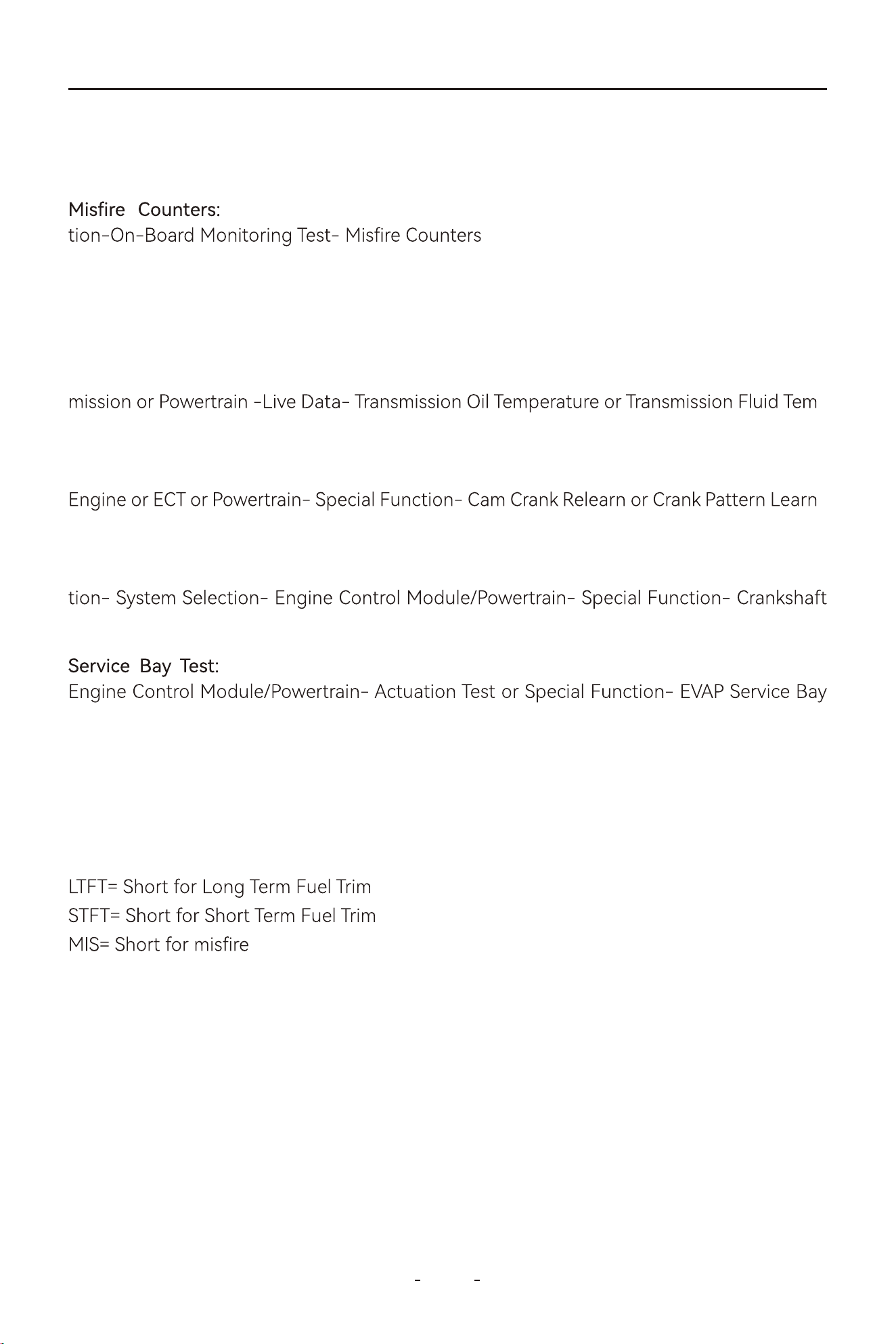
111
VD80 BT Diagnostic Tool
14. Appendix
MANUAL DIAGNOSIS- Region- OBDII- Auto Scan/Protocol Selec-
Transmission Oil Temperature: MANUAL DIAGNOSIS-REGION-Make-Model-Year-Trans-
-
perature
Cam Crank Relearn: MANUAL DIAGNOSIS- Region- Vehicle Selection- System Selection-
-
ing
Crankshaft Position Variation Sensor Relearn: MANUAL Diagnosis- Region- Vehicle Selec-
Position Variation Learn
MANUAL DIAGNOSIS- Region- Vehicle Selection- System Selection-
Test
VGT Turbo Calibration: MANUAL DIAGNOSIS- Region-Vehicle Selection- System Selection-
Drive Train Control Module- Special Function- Turbo Actuator Pre-Align/Self Calibrate
Readiness Status(Smog Check): MANUAL DIAGNOSIS-OBDII-I/M Readiness Status
Fuel Loop Status: MANUAL DIAGNOSIS-OBDII-Live Data- Fuel System 1, Fuel System 2
14.1 Navigation Path Quick Check
I/M Readiness Status= Technical term for Smog Check
VGT Turbo Actuator Calibration= Turbo Actuator Pre-Align/Self Calibrate
Cam Crank Relearn= Cam Pattern Relearn
Crankshaft Position Variation Learn= Crankshaft Relearn= CASE Learning= Gear Learning
14.2 Terms & Terminology Quick Check
Actuation Test= Active Test=Component Test= Bi-Directional Control
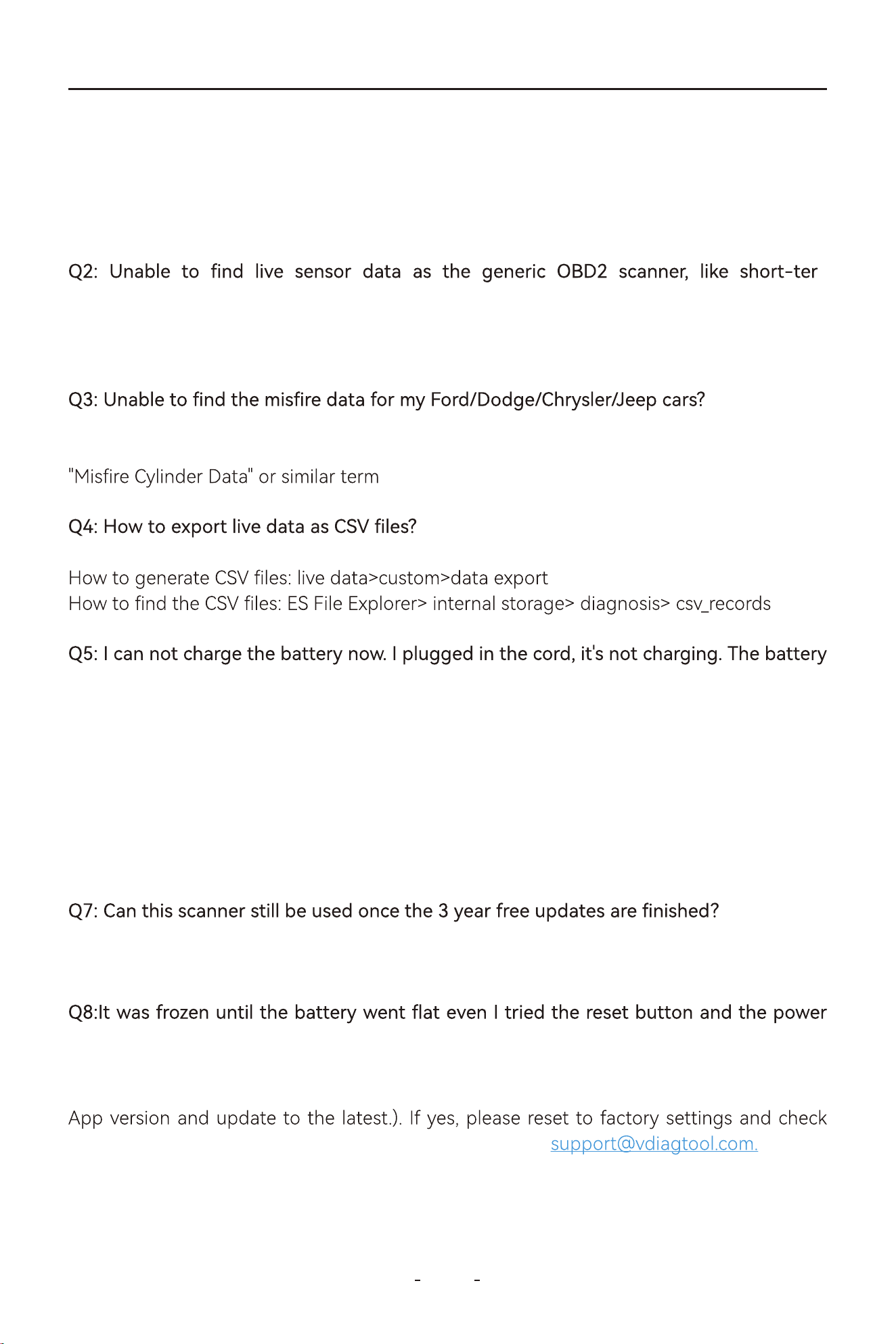
112
VD80 BT Diagnostic Tool
Q1:Ihaven'tfoundI/Mreadiness in the menu.
-
m/long-termfueltrim.
A:PleaseenterManual Diagnosis>SelectAmerica/Europe/Asia>Clickthe "OBDII" iconon
thetopleftofthescreen>AutoScan/SelectOBDIIProtocol>I/MReadiness
A: Please Select Manual Diagnosis-America/Europe/Asia>OBDII (On the top left of the
screen)>Auto Scanor Select OBDII Protocol for your car>OnBoard Monitor Test>Select
A:
Q6: Canscannertuneupcar?
A:Yesofcourse,youcanstilluseitslastupdatedsoftwarewhenitexpires,evenwhenit
A: Sor, VD80 BT Diagnostic Tool does not have the capability to tune up car.
expiresafterthreeyears.
A:PleaseenterDiagnosis>SelectAmerica/Europe/Asia>Clickthe"OBDII"icononthetopleft
ofthescreen>AutoScan/SelectOBDIIProtocol>LiveData>LTFT, STFT or similar term
isalmostdead,onlyabout10%left.
A:Pleasechargeitforoveranhour,unplugitfromthecharger,thenpressandholdthe
powerbuttonfor15secondsandseeifitsolvestheissue. PleaseunplugtheUSB-Ccable
fromthe Diagnostic Toolandpressandholdthepowerbuttonfor15s,andcheckifitcan
powerupsuccessfully.
button.
A:PleasemakesureyouhaveupdatedtheApptothelatestversion(To update the App to
the latest, go to Settings- About- App- click the arrow at the right side to check the latest
again.Ifitstilldoesnotwork,pleasereachusdirectlyvia
14.3 FAQs
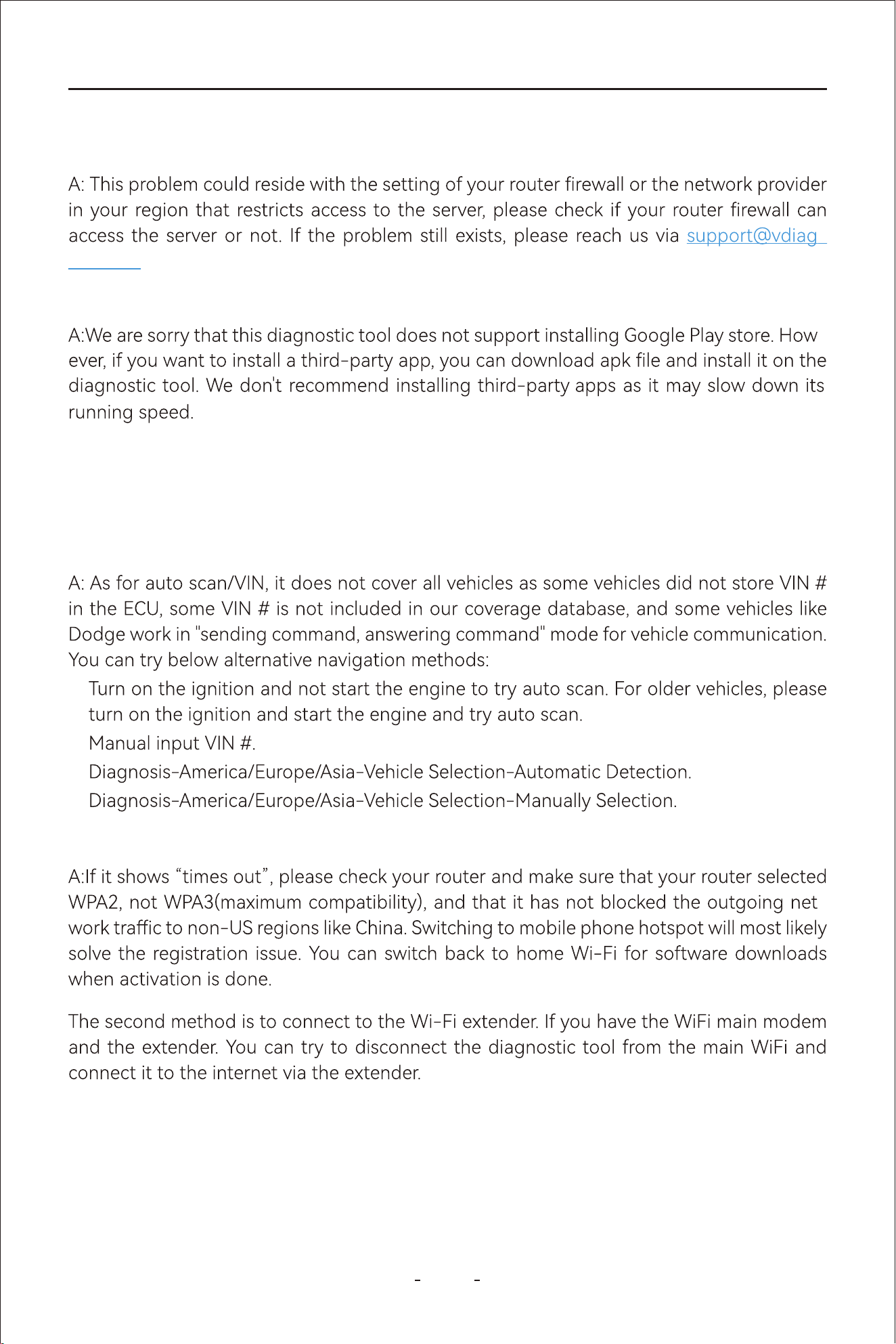
113
VD80 BT Diagnostic Tool
Q10.AnychancetoinstallGoogleplaystore?
Q11: So if no WiFi, you can't use the VD80 BT ?
A: WiFi wireless connection is the type of communication from the VCI to the machine and
has nothing to do with the WiFi internet connection.
-
Q12: Theautovincannotworkonmyvehicle.
Q13: Mydiagnostic toolcannotconnecttoWIFI.
-
1:
2:
3:
4:
Q9:I cannot update, I've tried wi- and cell phone as hotspot, however, keep telling me
failureconnection.
-
tool.com.
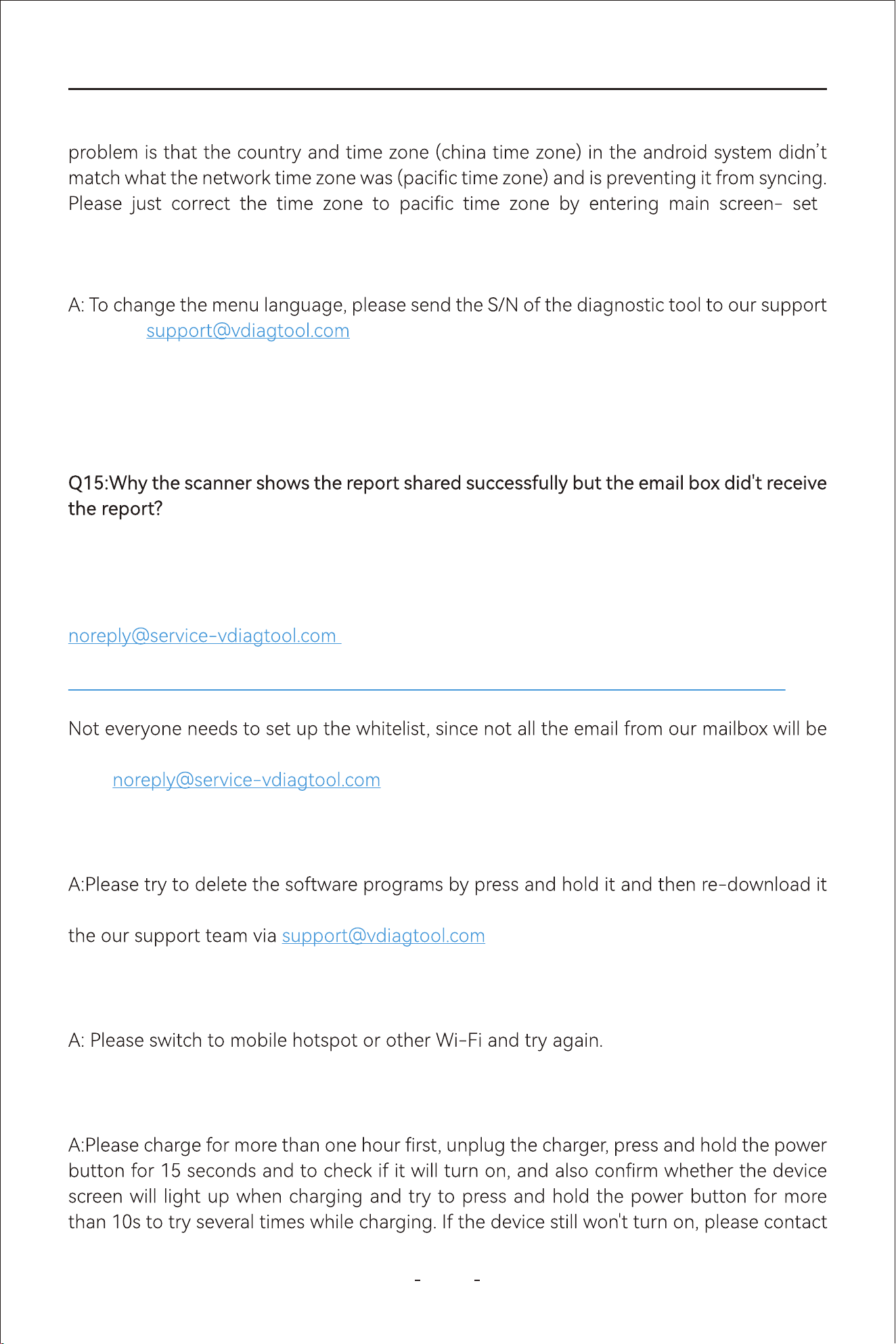
114
VD80 BT Diagnostic Tool
Q14: How can I change the menu language into Spanish?
team via and get Spanish software program authorization. When
the authorization is done, go to Settings on the diagnostic menu- language- Spanish to
change the language of the android tablet into Spanish, then go to Updates- download all
software programs. When all software programs in Spanish have been downloaded and
installed, you may use the diagnostic tool in Spanish
Ifithasconnectedtotheinternetbutshows“connectinternettosyncyourdevice”,the
-
tings-System-Date & Time-"selecttimezone".
A: All the repos are sent by our email: noreply@seice-vdiagtool.com, theemailmay be
blockedeventhedeviceshows"sendsuccessfully".
Q16:When you enter the diagnosis software program, it shows 'license exception' or
'Failed'errormessage.
againunderthe'Updates'tocheckwhetherthisissueissolvedornot.Ifnot,pleasecontact
withtheS/N of the diagnostic tool.
Q17:Browsercanaccessinternetnormally,butcannotdownloadtheupdatesunder"Up-
dates",promptedto'checkthenetworkconnection'intheUpdate.
Q18:Thedevicecannotbecharged/poweredonwhenconnectedwiththecarorplugged
intothecharger.
Sinceyouusegmail,youcanfollowbelowinstructionstowhitelistoursendingmailbox:
blockedbyreceivedmailbox.Youmayalsocheckyourjunkemailtoseeifthereisanyemail
from
.
https://downtimemonkey.com/blog/how-to-whitelist-an-email-address-in-gmail.php

115
VD80 BT Diagnostic Tool
Q20: If my diagnostic device is connected to the VCI box via WiFi, does that mean it can't
connect to my home WiFi?
A: This is not a correct understanding. The VCI WIFI is dierent from the home WIFI. While
connected to the VCI, you can also connect to the home WIFI to peorm software upgra-
des, etc.
Q19:Whenactivatingthedevice,showserrormessage"registrationfailure"afterentering
youremailaddress.