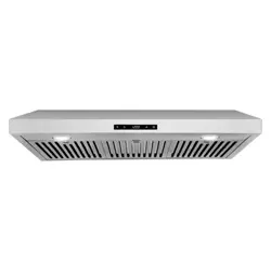
INSERT RANGE HOOD
COS-KS6U30(-BK)
COS-KS6U36(-BK)
INSTALLATION INSTRUCTIONS
AND USE & CARE GUIDE
READ AND SAVE THESE INSTRUCTIONS.
FOR RESIDENTIAL USE ONLY.
PLEASE LEAVE THESE INSTRUCTIONS WITH THIS UNIT FOR
THE OWNER.
PLEASE RETAIN THESE INSTRUCTIONS FOR FUTURE
REFERENCE.
IMPORTANT:
INSTALLER:
OWNER:
KS RANGE HOOD SERIES
Rev.24.04
2
THANK YOU FOR YOUR PURCHASE
Thank you for your purchase. We know that you have many brands and
products to choose from and we are honored to know that you have decided
to take one of our products into your home and hope that you enjoy it.
COSMO Appliances are designed according to the strictest safety and
performance standard for the North American market. We follow the most
advanced manufacturing philosophy. Each appliance leaves the factory after
thorough quality inspection and testing. Our distributors and our service
partners are ready to answer any questions you may have regarding how to
install, use and care for your products. We hope that this manual will help you
learn to use the product in the safest and most effective manner.
Before using this product, please read through this manual carefully.
Keep
this user manual in a safe place for future reference. Please ensure that other
persons using this product are familiar with these instructions as well.
If you have any questions or concerns, please contact the dealer from whom you
purchased the product, or contact our Customer Support at:
1-888-784-3108
Reach us online at:
www.cosmoappliances.com

3
TABLE OF CONTENTS
RANGE HOOD SAFETY ........................................................................................ 4
Important Safety Instructions ................................................................................. 5
INSTALLATION REQUIREMENTS ........................................................................ 7
Tools and Parts .......................................................................................................... 7
Location Requirements ............................................................................................ 9
Product Dimensions ................................................................................................ 10
Cabinet Clearances ................................................................................................. 12
Venting Requirements ............................................................................................. 13
Electrical Requirements ........................................................................................... 17
INSTALLATION INSTRUCTIONS ......................................................................... 18
Unpack Range .......................................................................................................... 19
Prepare Location ..................................................................................................... 20
Install Range Hood ................................................................................................. 25
Complete Installation ............................................................................................. 30
RANGE HOOD USE ............................................................................................. 31
Controls ...................................................................................................................... 31
RANGE HOOD CARE ......................................................................................... 33
Cleaning .................................................................................................................... 33
Replacing the LED Light ......................................................................................... 34
LIMITED WARRANTY ........................................................................................ 35
READ ALL INSTRUCTIONS BEFORE USING THE APPLIANCE
Your safety and the safety of others are very important.
We have provided many important safety messages in this manual and on
your appliance. Always read and obey all safety messages.
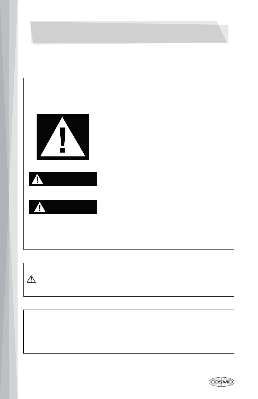
This is the safety alert symbol.
This symbol alerts you to potential hazards
that can kill or hurt you and others.
All safety messages will follow the safety alert
symbol and either the word "WARNING" or
"CAUTION." These words mean:
You can be killed or seriously injured if you
don't follow instructions.
A potentially hazardous situation which, if not
avoided, could result in minor or moderate
injury.
All safety messages will tell you what the potential hazard is, tell you how
to reduce the chance of injury, and tell you what can happen if the
instructions are not followed.
California Proposition 65 Warning
WARNING:
Cancer and Reproductive Harm - www.P65Warnings.ca.gov.
WARNING
CAUTION
4
RANGE HOOD SAFETY
WARNING: This appliance is intended for normal indoor residential use. It is
not approved for commercial use, outdoor installation, installation over an
outdoor BBQ grill, or any other application not specifically allowed by this
manual. Damage from improper installation or use of this appliance is not
covered by the product warranty.
5
IMPORTANT SAFETY INSTRUCTIONS
WARNING: TO REDUCE THE RISK OF
FIRE, ELECTRIC SHOCK, OR INJURY
TO PERSONS, OBSERVE THE
FOLLOWING:
• Use this unit only in the manner
intended by the manufacturer. If
you have questions, contact the
manufacturer.
• Before servicing or cleaning the
unit, switch the power off at the
service panel and lock the
service panel to prevent power
from being switched on
accidentally. When the service
disconnecting means cannot be
locked, securely fasten a
prominent warning device, such
as a tag to the service panel.
• Installation work and electrical
wiring must be done by qualified
person(s) in accordance with all
applicable codes and standards,
including fire-rated construction.
• Do not operate any fan with a
damaged cord or plug. Discard
fan or return to an authorized
service facility for examination
and/or repair.
• Ducted fans must always be
vented to the outdoors.
- CAUTION: For general
ventilating use only. Do not
use to exhaust hazardous or
explosive materials and
vapors.
- CAUTION: To reduce the risk
of fire and to properly
exhaust air, be sure to duct
air outside - do not vent
exhaust air into spaces
within walls or ceilings, or
into attics, crawl spaces or
garages.
• Sufficient air is needed for
proper combustion and
exhausting of gases through the
flue (chimney) of fuel burning
equipment to prevent
backdrafting. Follow the heating
equipment manufacturer’s
guideline and safety standards
such as those published by the
National Fire Protection
Association (NFPA), the
American Society for Heating,
Refrigeration and Air
Conditioning Engineers
(ASHRAE), and the local code
authorities.
• When cutting or drilling into the
wall or ceiling; do not damage
electrical wiring and other
hidden utilities.
WARNING: TO REDUCE THE RISK OF
A RANGE TOP GREASE FIRE:
• Never leave surface units
unattended at high settings.
Boilovers cause smoking and
greasy spillovers that may ignite.
Heat oils slowly on low or
medium settings.
READ AND SAVE THESE INSTRUCTIONS
6
IMPORTANT SAFETY INSTRUCTIONS
• Always turn the hood ON when
cooking at high heat or when
flambéing food (i.e. Crepes
Suzette, Cherries Jubilee,
Peppercorn Beef Flambé).
• Clean ventilating fans
frequently. Grease should not be
allowed to accumulate on the
fan or filter.
• Use proper pan sizes. Always use
cookware appropriate for the
size of the surface element.
WARNING: TO REDUCE THE RISK OF
INJURY TO PERSONS IN THE EVENT
OF A RANGE TOP GREASE FIRE,
OBSERVE THE FOLLOWING:*
• SMOTHER FLAMES with a close
fitting lid, cookie sheet, or metal
tray, then turn off the burner. BE
CAREFUL TO PREVENT BURNS. If
the flames do not go out
immediately, EVACUATE AND
CALL THE FIRE DEPARTMENT.
• NEVER PICK UP A FLAMING PAN
- you may be burned.
• DO NOT USE WATER, including
wet dishcloths or towels - a
violent steam explosion will
result.
• Use an extinguisher ONLY if:
- You know you have a class
ABC extinguisher, and you
already know how to
operate it.
- The fire is small and
contained in the area where
it started.
- The fire department is being
called.
- You can fight the fire with
your back to an exit.
* Based on "Kitchen Fire Safety Tips"
published by NFPA.
WARNING: TO REDUCE THE RISK OF
FIRE, USE ONLY METAL DUCTWORK.
WARNING: To reduce the risk of fire
or electrical shock, do not use this
fan with any solid-state speed
control device.
WARNING: Do not let children near
this appliance. Do not let children
play with this appliance. Keep all
packaging materials out of children’s
reach. Properly dispose the
packaging materials after this
appliance is unpacked.
• The manufacturer declines all
responsibility in the event of
failure to observe the
instructions given here for
installation, maintenance, and
suitable use of the product.
• The manufacturer further
declines all responsibility for
injury due to negligence and the
warranty of the unit
automatically expires due to
improper maintenance.
READ AND SAVE THESE INSTRUCTIONS
7
INSTALLATION REQUIREMENTS
Tools and Parts
Gather the required tools and parts before starting installation. Read and
follow the instructions provided with any tools listed here.
Tools Needed
• Level
• Drill
• 3/32" (2.5 mm) drill bit for pilot holes
• Pencil
• Tape measure or ruler
• Phillips screwdriver
• Jigsaw or keyhole saw
• Hand gloves
Parts Needed
• Duct system
• Duct clamps or HVAC foil tape
• Caulking gun and weatherproof caulking compound

8
Parts Supplied
• Range hood (main core) with blower and LED lights installed
• Metal filters (3)
• L-shape wall mounting brackets (2)
• Top round vent transition damper
• Top rectangular vent transition damper
• Top vent cover – for rear venting installations
• Rear rectangular vent transition damper
• 6" round aluminum duct
• Remote control
• M6 expansion mounting screws – for concrete wall (4)
• 4 x 40 mm mounting screws – for drywall (4)
• 4 x 16 mm mounting screws – for cabinet (4)
• M8 wall anchors (4)
• M4 washers (4)
• 4 x 8 mm screws – for vent transition dampers (16)
• 4 x 12 mm screws – for L-shape mounting brackets (4)

9
Location Requirements
IMPORTANT:
• Observe all governing codes and ordinances.
Have a qualified technician install the range hood. It is the installer’s
responsibility to comply with installation clearances specified on the
model/serial/rating plate. The model/serial/rating plate is located inside the
range hood on the housing of the blower motor assembly.
Range hood location should be away from strong draft areas, such as
windows, doors, and strong heating vents.
Cabinet opening dimensions that are shown must be used. Given dimensions
provide minimum clearance. Consult the cooktop/range manufacturer
installation instructions before making any cutouts.
Grounded electrical outlet is required. See the "Electrical Requirements"
section.
The range hood is supplied with venting adapters for top vented or rear
vented installations.
All openings in ceiling and wall where range hood will be installed must be
sealed.
For Mobile Home Installations:
The installation of this range hood must conform to the Manufactured Home
Construction Safety Standards, Title 24 CFR, Part 328 (formerly the Federal
Standard for Mobile Home Construction and Safety, Title 24, HUD, Part 280)
or when such standard is not applicable, the standard for Manufactured
Home Installation 1982 (Manufactured Home Sites, Communities and Setups)
ANSI A225.1/NFPA 501A or latest edition, or with local codes.
10
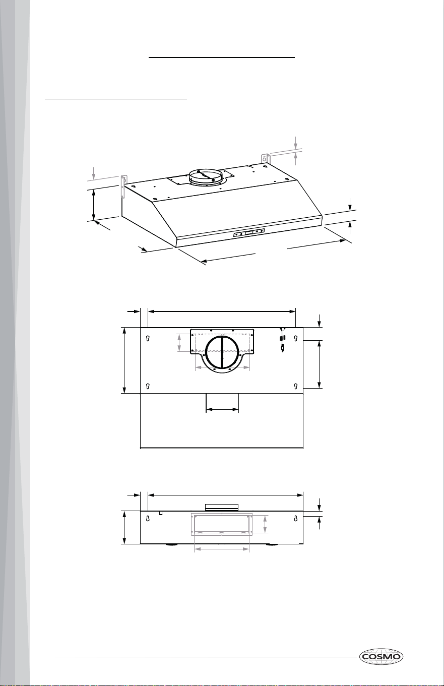
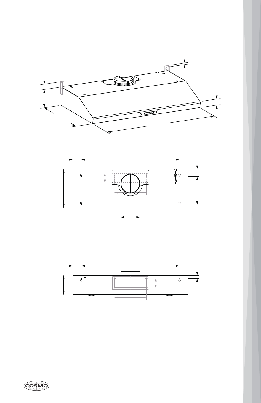
Product Dimensions
30" Model: COS-KS6U30(-BK)
29 ¹⁄₂ in
(75.0 cm)
22 in
(55.8 cm)
6 in
(15.3 cm)
¹⁄₂ in
(1.2 cm)
2 in
(5.1 cm)
1 ⁵⁄₈ in
(4.1 cm)
26 ³⁄₄ in
(68.0 cm)
12 in
(30.4 cm)
8 ¹¹⁄₁₆ in
(22.0 cm)
2 ³⁄₈ in
(6.0 cm)
1 ³⁄₈ in
(3.5 cm)
3 ³⁄₁₆ in
(8.1 cm)
9 ¹⁵⁄₁₆ in
(25.2 cm)
26 ³⁄₄ in
(68.0 cm)
1 ³⁄₈ in
(3.5 cm)
6 in
(15.2 cm)
1 in
(2.5 cm)
9 ¹⁵⁄₁₆ in
(25.2 cm)
3 ³⁄₁₆ in
(8.1 cm)
5 ¹⁵⁄₁₆ in
(15.0 cm)
11
36" Model: COS-K-KSS66UU336 6(-BK)
6 in
(15.3 cm)
35 ⁷⁄₁₆ in
(90.0 cm)
22 in
(55.8 cm)
¹⁄₂ in
(1.2 cm)
2 in
(5.1 cm)
1 ⁵⁄₈ in
(4.1 cm)
30 ⁵⁄₁₆ in
(77.0 cm)
12 in
(30.4 cm)
8 ¹¹⁄₁₆ in
(22.0 cm)
2 ³⁄₈ in
(6.0 cm)
2 ⁹⁄₁₆ in
(6.5 cm)
3 ³⁄₁₆ in
(8.1 cm)
9 ¹⁵⁄₁₆ in
(25.2 cm)
30 ⁵⁄₁₆ in
(77.0 cm)
2 ⁹⁄₁₆ in
(6.5 cm)
6 in
(15.2 cm)
1 in
(2.5 cm)
9 ¹⁵⁄₁₆ in
(25.2 cm)
3 ³⁄₁₆ in
(8.1 cm)
5 ¹⁵⁄₁₆ in
(15.0 cm)
12
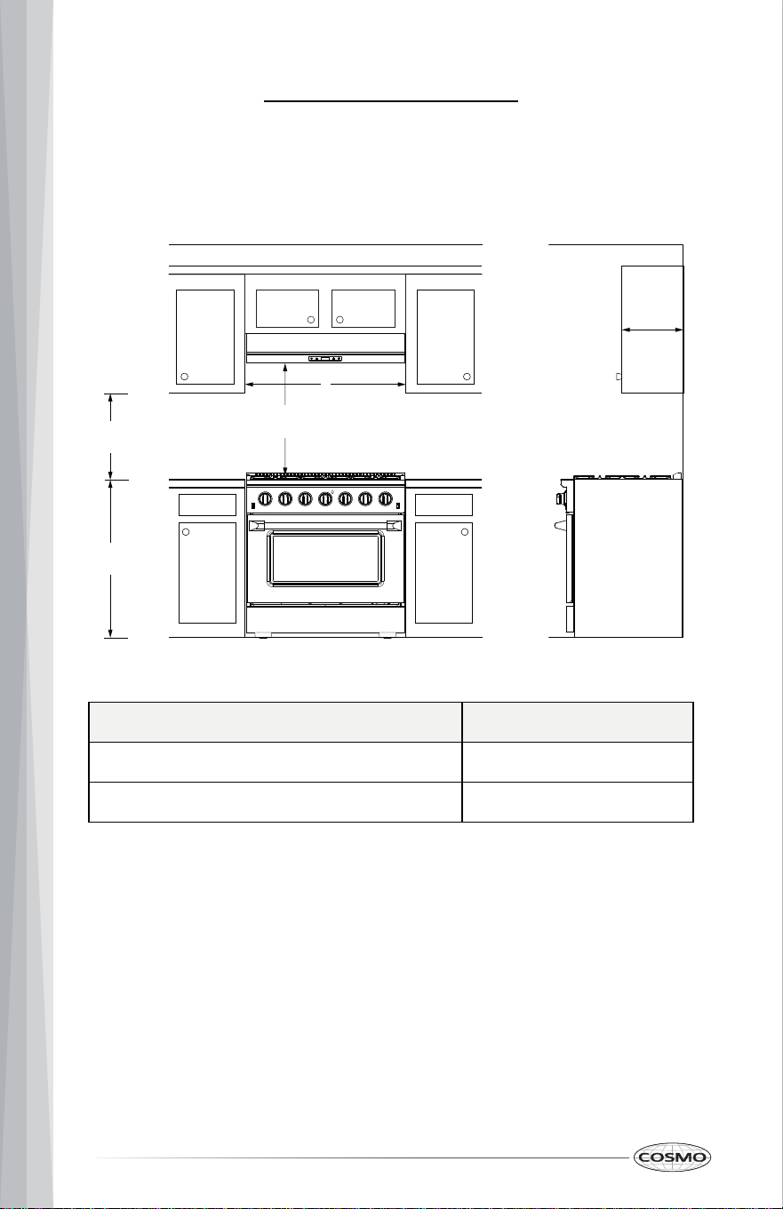
Cabinet Clearances
Given dimensions are minimum clearances.
Under Cabinet Range Hood
Model A
30" Model: COS-KS6U30(-BK) 29 ¹⁄₂" (75.0 cm)
36" Model: COS-KS6U36(-BK)
IMPORTANT:
• 25 ⁹⁄₁₆" (65.0 cm) minimum and 36" (91.4 cm) suggested maximum
clearances between cooking surface and bottom of the range hood.
• For ducted wall venting installations using a 90° elbow, 12" (30.5 cm)
minimum overhead cabinet clearance below the wall venting opening is
required.
12"
(30.5 cm)
Overhead
Cabinet
Depth
A
Max. 36" (91.4 cm)
Min. 25 ⁹⁄₁₆" (65.0 cm)
18"
(45.7 cm)
36"
(91.4 cm)
35 ⁷⁄₁₆" (90.0 cm)
13
Venting Requirements
(Ducted installations only)
• Duct system must terminate to the outdoors
• Do not terminate the duct system in an attic or other enclosed area.
• Do not use 4" (10.2 cm) laundry-type wall cap.
• Use a 6" (15.2 cm) round metal duct or a 3 ¹⁄₄" x 10" (8.3 x 25.4 cm)
rectangular metal duct. Rigid metal duct is recommended. Plastic o r
metal foil duct is not recommended.
• The length of duct system and number of elbows should be kept to a
minimum to provide efficient performance.
For the most efficient and quiet operation:
• Use rigid metal duct.
• Use no more than three 90° elbows.
• Make sure there is a minimum of 24" (61.0 cm) of straight duct between
the elbows if more than 1 elbow is used.
• Do not install 2 elbows together.
• Use clamps to seal all joints in the duct system.
• The duct system must have a damper. If the roof or wall cap has a
damper, do not use the damper supplied with the range hood.
• Use caulking to seal exterior wall or roof opening around the cap.
• The size of the duct should be uniform.
Cold Weather Installations:
An additional backdraft damper should be installed to minimize backward
cold air flow and a thermal break should be installed to minimize conduction
of outside temperatures as part of the duct system. The damper should be on
the cold air side of the thermal break.
The break should be as close as possible to where the duct system enters the
heated portion of the house.
Makeup Air:
Local building codes may require the use of makeup air systems when using
ventilation systems greater than specified CFM of air movement. The specified
CFM varies from locale to locale. Consult your HVAC professional for specific
requirements in your area.
14
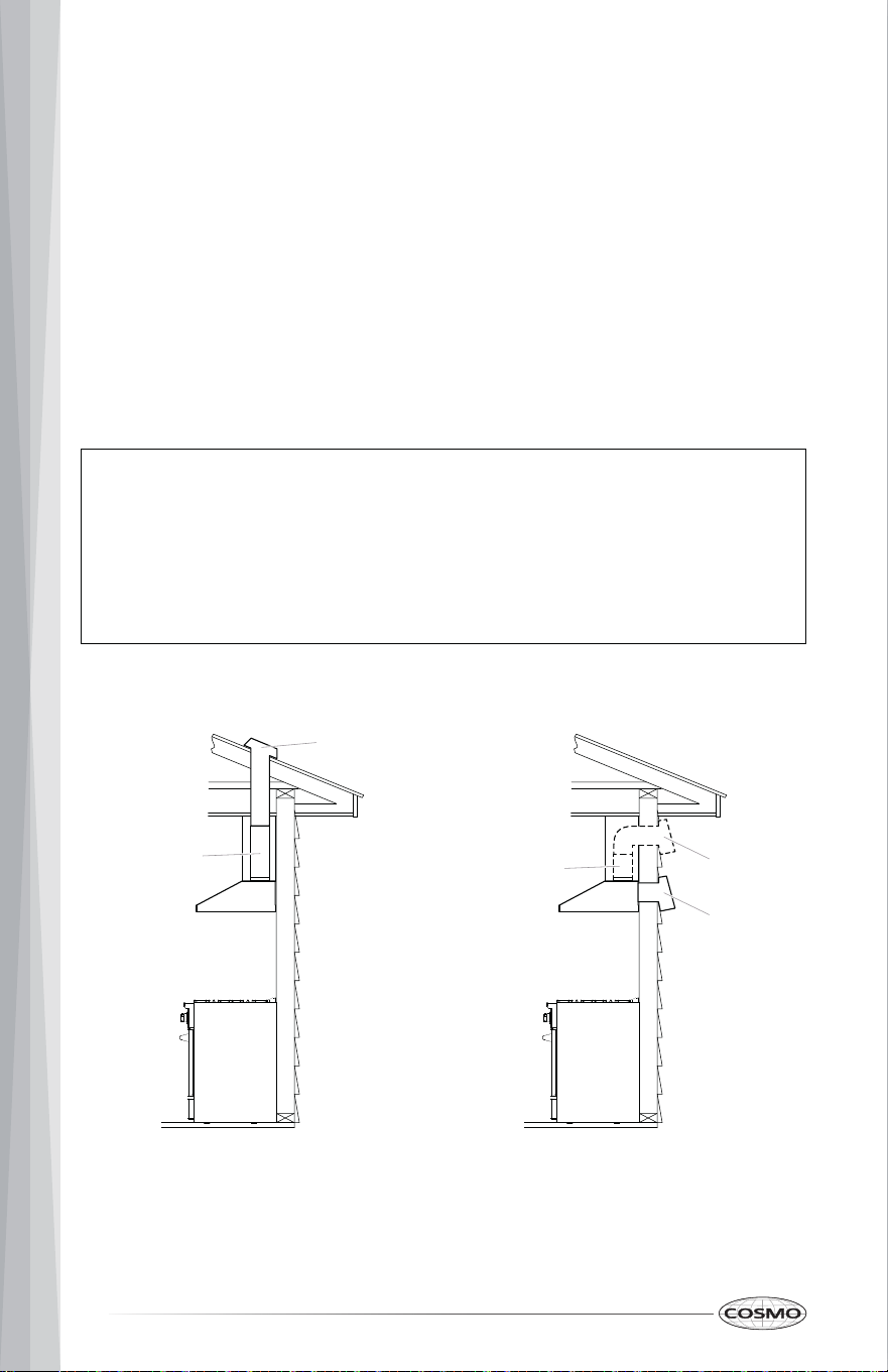
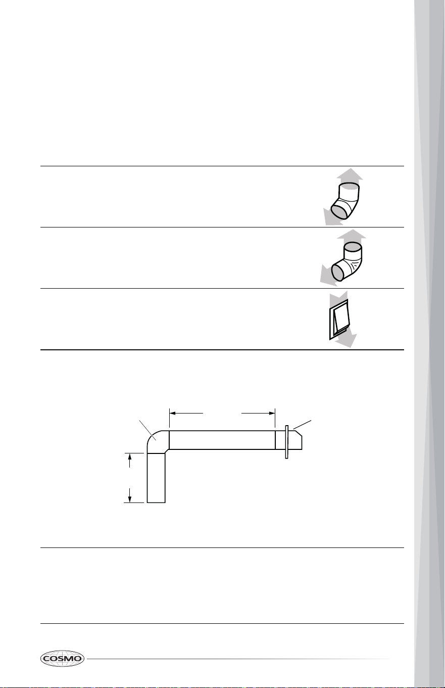
Venting Methods
NOTE:
Roof Venting Wall Venting
A. Roof cap
B. Round/Rectangular duct
through roof
• This range hood can be set for top venting or rear venting. A 6" (15.2 cm)
round or a 3 ¼" x 10" (8.3 cm x 25.4 cm) rectangular duct system is
recommended. The duct system needed for installation is not included.
• The duct system for venting out of the top of range hood can be
terminated either through the roof or wall. A round transition damper
suitable for 6" (15.2 cm) round duct and a rectangular transition damper
suitable for 3 ¼" x 10" (8.3 cm x 25.4 cm) rectangular duct are provided.
• The duct system for venting out the rear of the range hood must be
terminated through the wall. A rectangular transition damper suitable for
3 ¼" x 10" (8.3 cm x 25.4 cm) rectangular duct is provided.
A. Wall cap
B. Round/Rectangular duct
through wall
C. Rectangular duct through wall
• Flexible vent is not recommended. Flexible vent creates back pressur e
and air turbulence that gently reduces performance.
• If exhaust ducting is less than 5 ¹⁵⁄₁₆" (15.0 cm) in diameter or if f lat
ducting is used, the noise level of the range hood may increase and t he
exhaustion may be less efficient.
A
B
A
B
C
15
Duct Piece 6" (15.2 cm) Round
45° elbow
2.5 ft (0.8 m)
90° elbow 5.0 ft (1.5 m)
0.0 ft (0.0 m) 6" (15.2 cm) wall cap
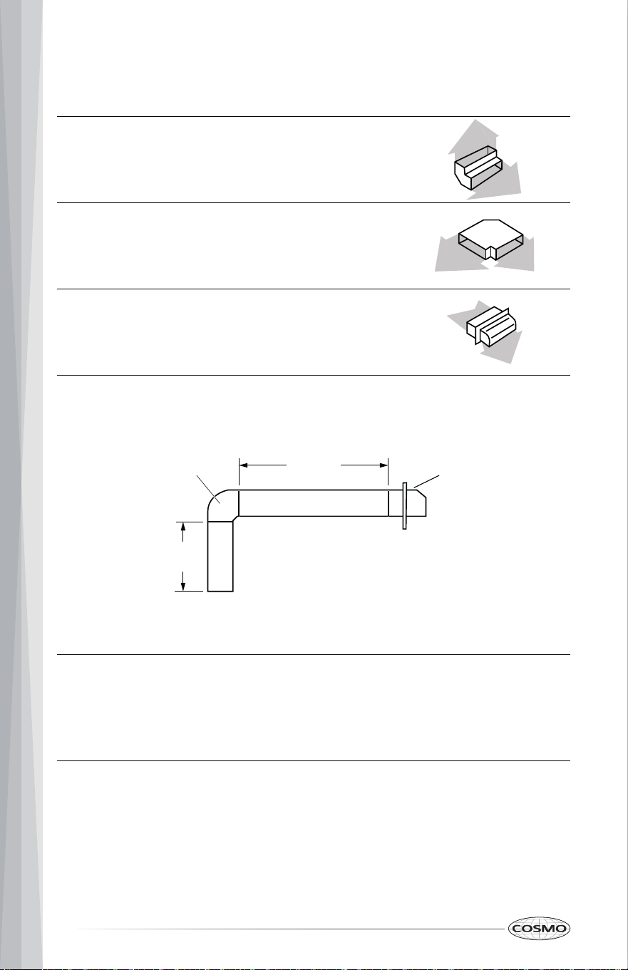
Calculating Duct System Length
To calculate the length of the system you need, add the equivalent feet
(meters) for each duct piece used in the system. Use no more than three 90°
elbows.
6" (15.2 cm) Round Duct System
Maximum recommended duct length is 35 ft (10.7 m).
Maximum length = 35 ft (10.7 m)
3 ft (0.9 m) straight
1 - 90° elbow
6 ft (1.8 m) straight
1 – wall cap
= 3.0 ft (0.9 m)
= 5.0 ft (1.5 m)
= 6.0 ft (1.8 m)
= 0.0 ft (0.0 m)
System length
= 14.0 ft (4.3 m)
Example Round Duct System
90˚ elbow Wall cap
3 ft
(0.93 m)
6 ft (1.8 m)
16
Duct Piece
3 ¼" x 10" (8.3 cm x 25.4 cm) Rectangular Duct System
90° elbow
3 ¼" x 10" (8.3 cm x 25.4 cm) Rectangular
5.0 ft (1.5 m)
Flat elbow 12.0 ft (3.7 m)
0.0 ft (0.0 m) 6" (15.2 cm) wall cap
Maximum recommended duct length is 35 ft (10.7 m).
Example Rectangular Duct System
Maximum length = 35 ft (10.7 m)
3 ft (0.9 m) straight
1 - 90° elbow
6 ft (1.8 m) straight
1 – wall cap
= 3.0 ft (0.9 m)
= 5.0 ft (1.5 m)
= 6.0 ft (1.8 m)
= 0.0 ft (0.0 m)
System length
= 14.0 ft (4.3 m)
90˚ elbow Wall cap
3 ft
(0.93 m)
6 ft (1.8 m)

17
Electrical Requirements
Observe all governing codes and ordinances.
Ensure that the electrical installation is adequate and in conformance with
National Electrical Code, ANSI/NFPA 70 (latest edition), or CSA Standards
C22.1-94, Canadian Electrical Code, Part 1 and C22.2 No. 0-M91 (latest edition)
and all local codes and ordinances.
If codes permit and a separate ground wire is used, it is recommended that a
qualified electrician determine that the ground path is adequate.
A copy of the above code standards can be obtained from:
National Fire Protection Association
1 Batterymarch Park
Quincy, MA 02169-7471
CSA International
8501 East Pleasant Valley Road
Cleveland, OH 44131-5575
• A 120-volt, 60 Hz., AC-only, 2-amp, fused electrical circuit is required.
• If the house has aluminum wiring, follow the procedure below:
- Connect a section of solid copper wire to the pigtail leads.
- Connect the aluminum wiring to the added section of copper wire
using special connectors and/or tools designed and UL Listed for
joining copper to aluminum.
Follow the electrical connector manufacturer's recommended procedure.
Aluminum/copper connection must conform with local codes and industry
accepted wiring practices.
• Wire sizes and connections must conform with the rating of the appliance
as specified on the model/serial/rating plate. The model/serial/rating
plate is located behind the middle metal filter on the blower housing of
the range hood.
• Wire sizes must conform to the requirements of the National Electrical
Code, ANSI/NFPA 70 (latest edition), or CSA Standards C22. 1-94,
Canadian Electrical Code, Part 1 and C22.2 No. 0-M91 (latest edition) and
all local codes and ordinances.
18
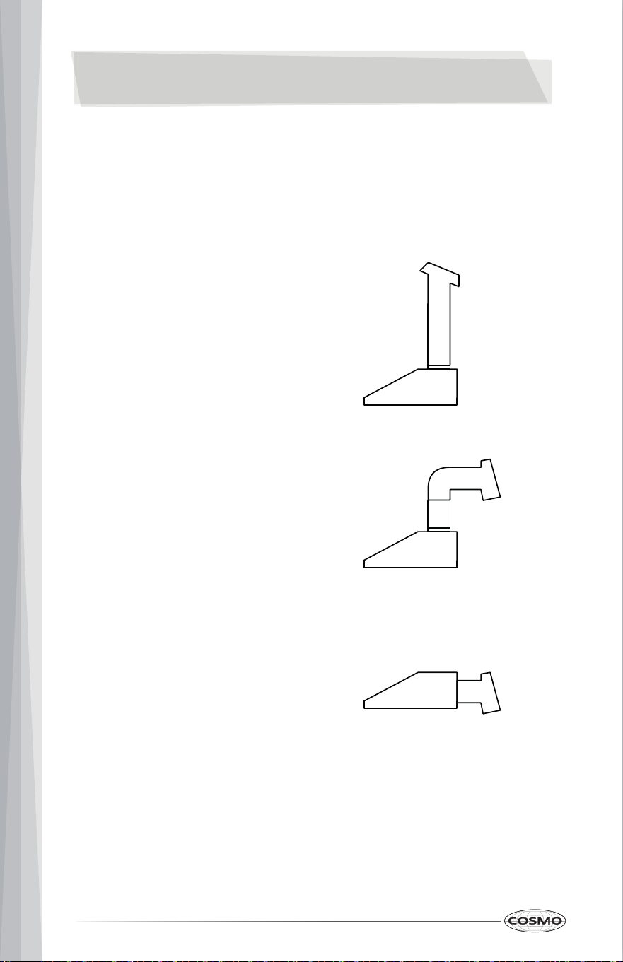
• Top Venting
(Roof Venting)
• Top Venting
(Wall Venting)
INSTALLATION INSTRUCTIONS
IMPORTANT: This appliance shall be installed only by authorized persons and
in accordance with the manufacturer's installation instructions.
This range hood is designed for adaptation to the following types of
• Rear Venting
(Wall Venting)
Please follow the instructions provided for your type of ventilation.
19
Unpack Range Hood
• Remove installations parts carefully. Wear hand gloves to protect against
sharp edges.
• Confirm that all installations parts have been removed from the shipping
carton and the range hood canopy.
WARNING EXCESSIVE WEIGHT HAZARD
• Use two or more people to move and install range hood.
• Failure to do so can result in back or other injury.
1. Remove all the parts stored in the carton.
2. Remove the foams, tapes, and protective films covering the parts.
3. Select a flat surface for assembling the range hood. Place covering over
that surface.
4. Using 2 or more people, lift range hood onto covered surface.
20
Prepare Location
• It is recommended that the duct system be installed before the range
hood is installed. The duct system needed for installation is not included.
• Before making cutouts, make sure there is proper clearance within the
ceiling or wall for duct fittings.
1. Disconnect power.
2. Determine which venting method to use: top or rear.
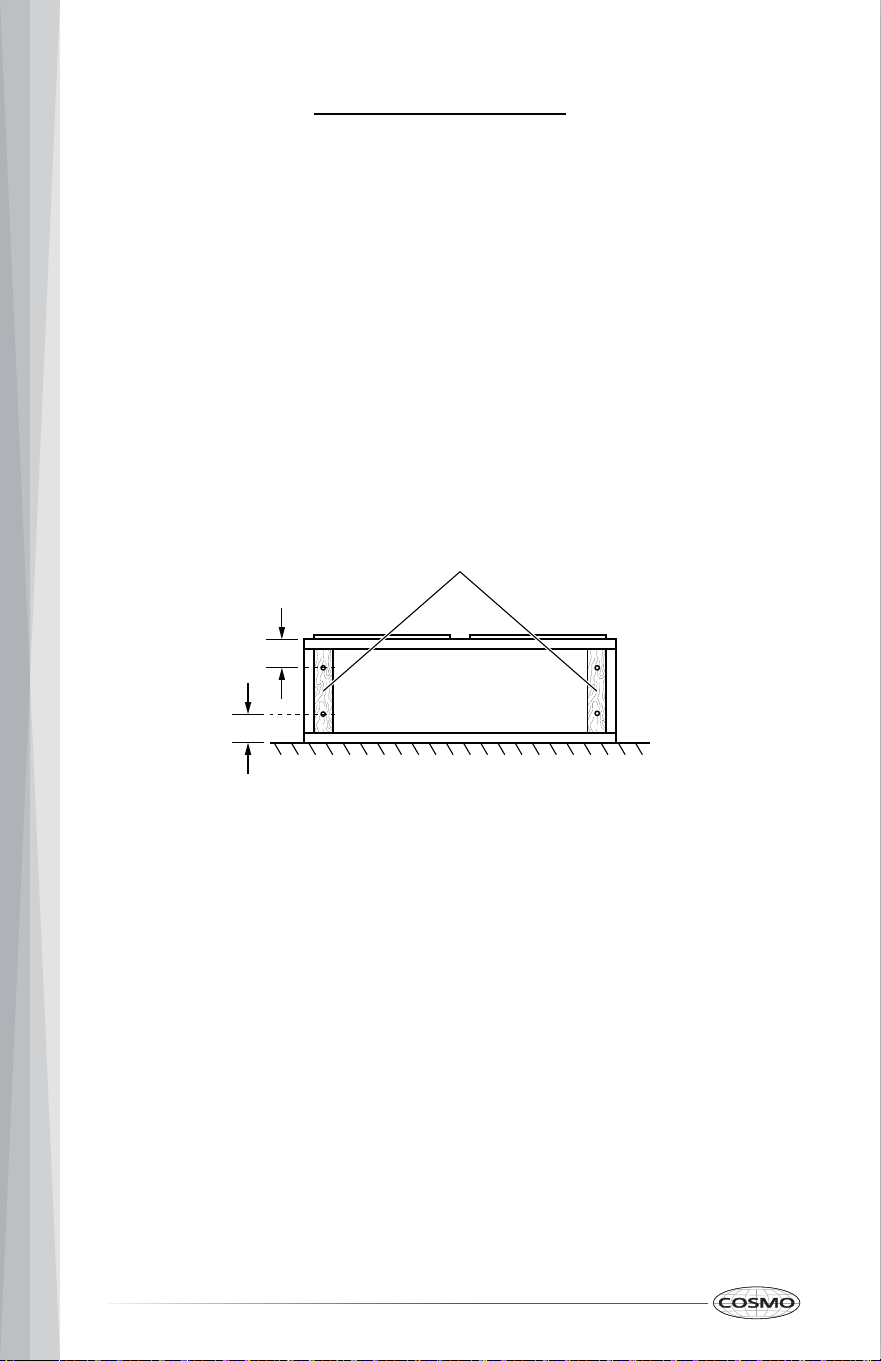
3. If cabinet has recessed bottom, add wood filler strips on each side. Install
screws to attached filler strips in locations shown.
Wood filler strips
(recessed cabinet bottoms only)
Cabinet
bottom
3" (7.6 cm)
3" (7.6 cm)
Wall
21
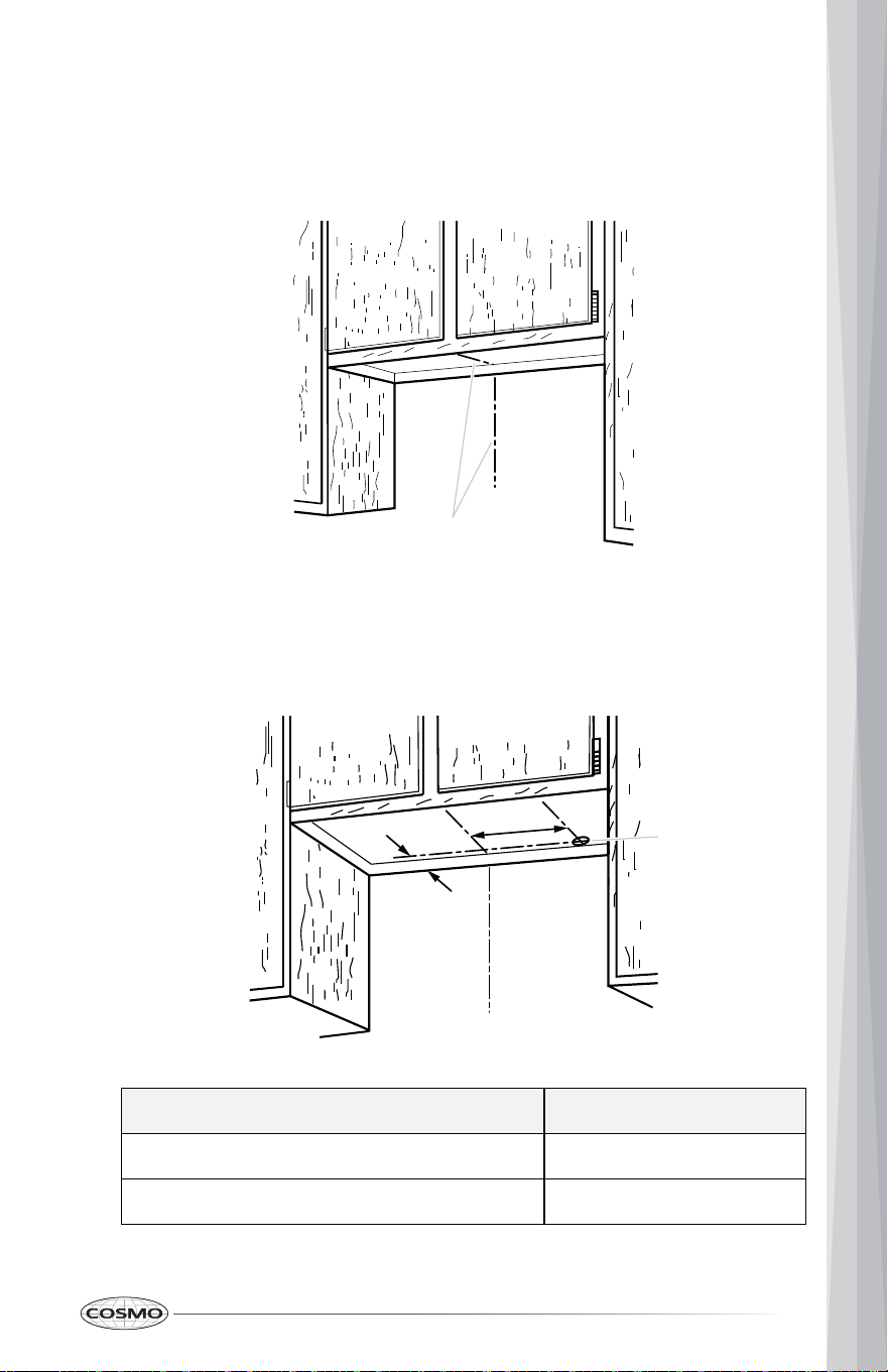
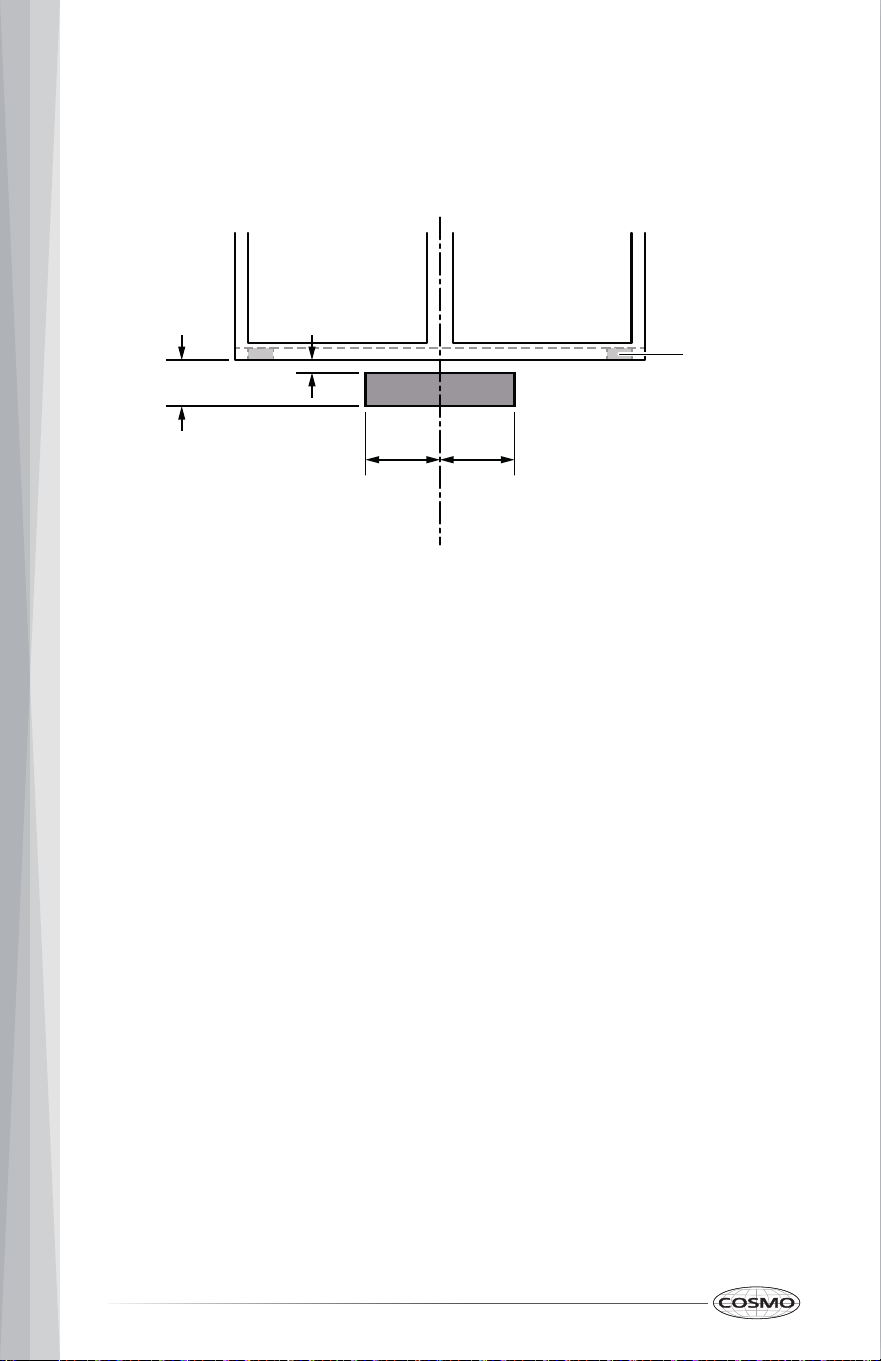
Prepare Wiring Hole
1. Determine and clearly mark a vertical centerline on the wall and cabinet
in the area the vent opening will be made.
2. Mark a line distance "A" from the right of the centerline on the underside
Model A
11" (28.0 cm)30" Model: COS-KS6U30(-BK)
of the cabinet. Mark the point on this line that is 2" (5.1 cm) from back
wall. Drill a 1 ¼" (3.2 cm) diameter hole through the cabinet at this point.
36" Model: COS-KS6U36(-BK) 11" (28.0 cm)
Centerline
Centerline
A
1 ¼" (3.2 cm)
wiring hole
2" (5.1 cm)
from wall
22
Prepare Venting Cutout
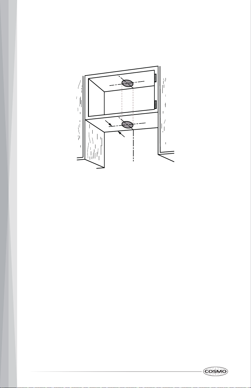
Roof Venting
Style 1 – Cut Openings for 6" (15.2 cm) Round Vent System
To make a 6 ¹⁄₄" (15.9 cm) circular vent opening on the underside of the
cabinet bottom:
To make a 6 ¹⁄₄" (15.9 cm) circular vent opening on the underside of the
cabinet top:
1. Mark a line 4 ¹⁄₂" (11.5 cm) from the back wall on the centerline of the
underside of cabinet.
2. Use a compass or a circle template to draw a 6 ¹⁄₄" (15.9 cm) circle.
3. Use saber or keyhole saw to cut the circular opening for vent.
1. Mark a centerline on the underside of the top of cabinet.
2. Using the distance from rear cabinet frame to the circular vent opening
on cabinet bottom as reference, draw a 6 ¹⁄₄" (15.9 cm) circle on the
underside of the top of cabinet directly above the circular vent opening
on cabinet bottom .
3. Use saber or keyhole saw to cut the circular vent opening.
Centerline
4 ¹⁄₂"
(11.5 cm)
from wall
23
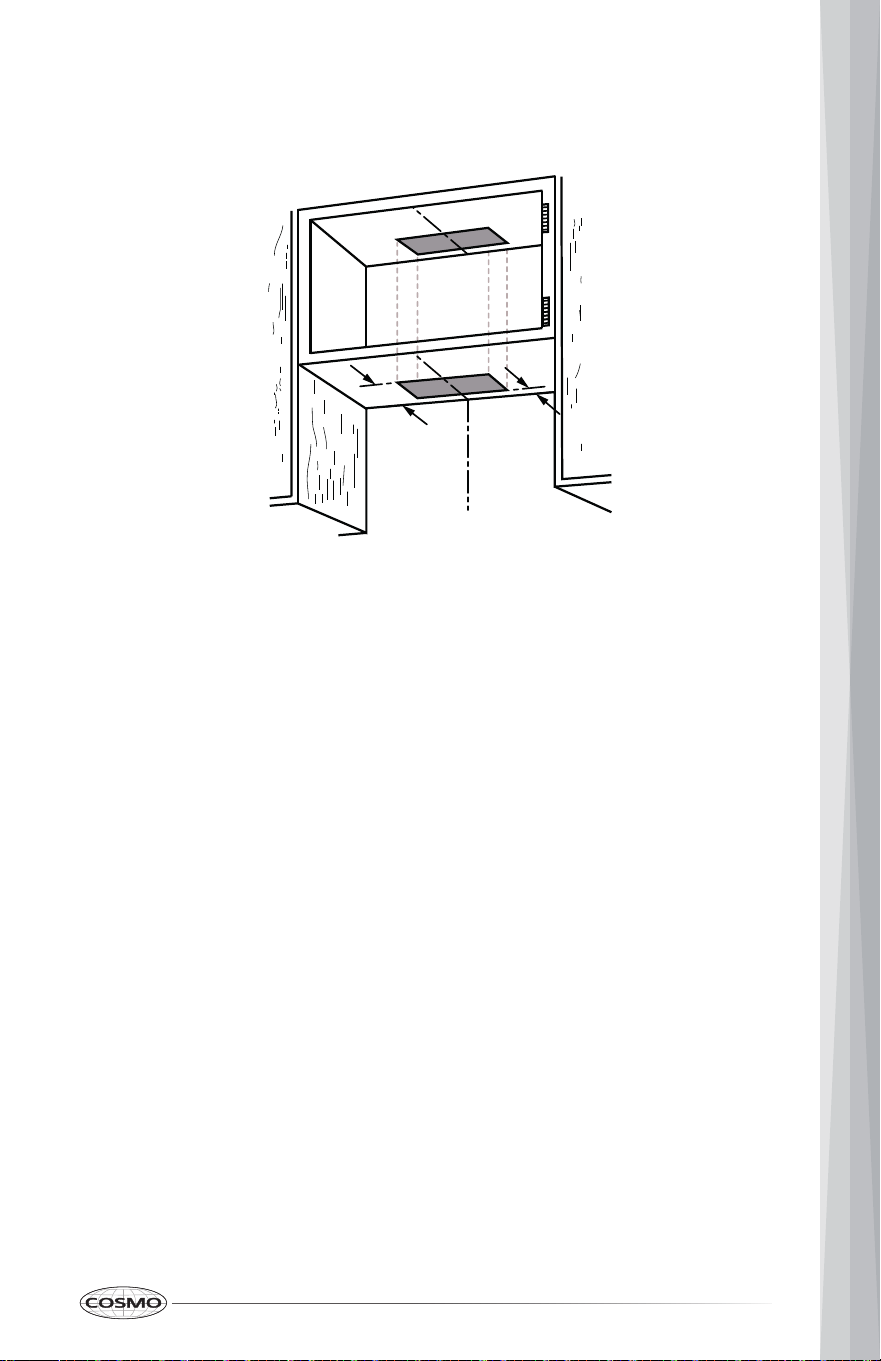
Style 2 – Cut Openings for 3 ¼" x 10" (8.3 cm x 25.4 cm) Rectangular Vent
System
To make a 4" x 10 ½" (10.2 cm x 26.7 cm) rectangular vent opening on the
underside of cabinet bottom:
To make a 4" x 10 ½" (10.2 cm x 26.7 cm) rectangular vent opening on the
underside of the cabinet top:
1. Mark 2 lines ¹³⁄₁₆" (2.0 cm) and 4 ¹³⁄₁₆" (12.2 cm) from the back wall on the
centerline of the underside of cabinet.
2. Mark lines 5 ¼" (13.3 cm) to the left and right of the centerline on the
underside of cabinet.
3. Use saber or keyhole saw to cut a rectangular opening for vent.
1. Mark a centerline on the underside of the top of cabinet.
2. Using the distance from rear cabinet frame to the rectangular vent
opening on cabinet bottom as reference, draw a 4" x 10 ¹⁄₂" (10.2 cm x
26.7 cm) rectangle on the underside of the top of cabinet directly above
the rectangular vent opening on cabinet bottom .
3. Use saber or keyhole saw to cut the rectangular vent opening.
Centerline
4 ¹³⁄₁₆"
(12.2 cm)
from wall
¹³⁄₁₆"
(2.0 cm)
from wall
24
Wall Venting
Style 3 – Cut Openings for 3 ¼" x 10" (8.3 cm x 25.4 cm) Rectangular Vent
System
To make a 4" x 10½" (10.2 cm x 26.7 cm) rectangle vent opening in the wall:
Install Vent System
1. Mark 2 lines by measuring ¹⁄₄" (0.6 cm) and 4 ¹⁄₄" (10.8 cm) down from
underside of cabinet and mark on the centerline on the back wall.
2. Mark lines 5 ¼" (13.3 cm) to the left and right of the centerline on the wall.
3. Use saber or keyhole saw to cut the circular vent opening.
1. Install vent through the vent opening in cabinet or wall. Complete venting
system according to the selected venting method. See "Venting
Requirements" section.
2. Use caulking to seal exterior wall or roof opening around the cap.
Centerline
Wood filler
strips
(recessed
cabinet
bottoms
only)
¹⁄₄"
(0.6 cm)
Cabinet
front
4 ¹⁄₄"
(10.8 cm)
5 ¼"
(13.3 cm)
5 ¼"
(13.3 cm)
25
Install Range Hood
WARNING EXCESSIVE WEIGHT HAZARD
• Use two or more people to move and install range hood.
• Failure to do so can result in back or other injury.
1. Remove the metal filters. See the "Range Hood Care" section.
2. Remove any foam shipping pad from behind the blower motor if exists.
3. Lift the range hood up under cabinet and determine final location by
centering beneath cabinet.
4. For cabinet mounting only: Mark on the underside of cabinet the
location of the 4 keyhole mounting slots on the top of range hood. Set
range hood aside on a covered surface.
Keyhole
mounting slot
For wall mounting only: Mark on the wall the location of the 2 keyhole
mounting slots on the rear of range hood. Set range hood aside on a
covered surface.
(Optional) Depending on cabinet configuration, the 2 L-shape wall
mounting brackets may be used instead. Attach brackets to range hood
with the 4 - 4 x 12 mm screws provided, and mark on the wall the location
of the 2 keyhole mounting slots on brackets.
26
NOTE:
Vent Transition Damper Installation
Determine whether the range hood will be installed using either a top or rear
vent connection.
• If the wall cap is directly behind the vent connector, the dampers in the
connector and wall cap must not interfere. Remove the vent connector
damper if they interfere.
Drill pilot hole
¼"
(6.4 cm)
5. Use ³⁄₃₂" (2.5 mm) drill bit to drill pilot holes on cabinet bottom or wood
stud as shown. For keyhole mounting slots on wall without stud, use
appropriate drill bit to drill pilot holes as shown and install the wall
anchors .for drywall or the M6 mounting screws for concrete wall.
6. With the washers provided, install the 4 - 4.5 x 16 mm mounting screws in
pilot holes on cabinet bottom or the 2 - 4 x 40 mm mounting screws in
pilot holes on wall. Leave about ¹⁄₄" (6.4 mm) space between screw heads
and cabinet to slide range hood into place.
27
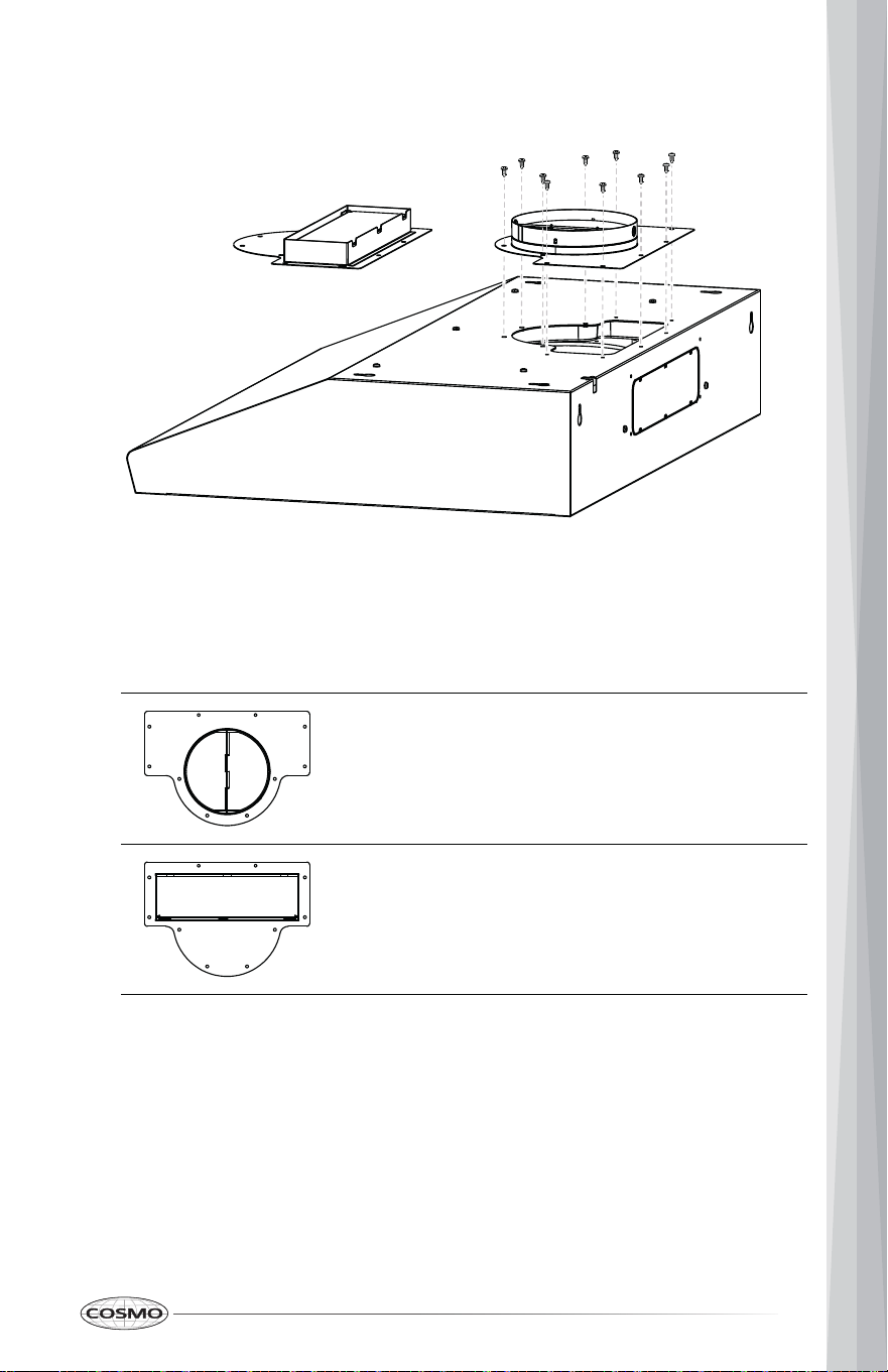
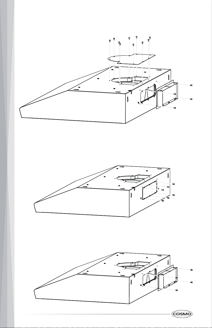
Top Vent Transition Damper Installation
Round vent transition damper for 6" (15.2 cm)
round duct system.
Rectangular vent transition damper for 3 ¼" x 10"
(8.3 cm x 25.4 cm) rectangular duct system.
2. Remove any tape from damper flap if present.
OR
supplied.
1. Attach the top vent transition damper using the 4 x 8 mm screws
28
Rear Vent Transition Damper Installation
knockout.
1. Remove the screws around the rear vent knockout, and remove the
screws supplied.
2. Attach the rear rectangular vent transition damper using the 4 x 8 mm
29
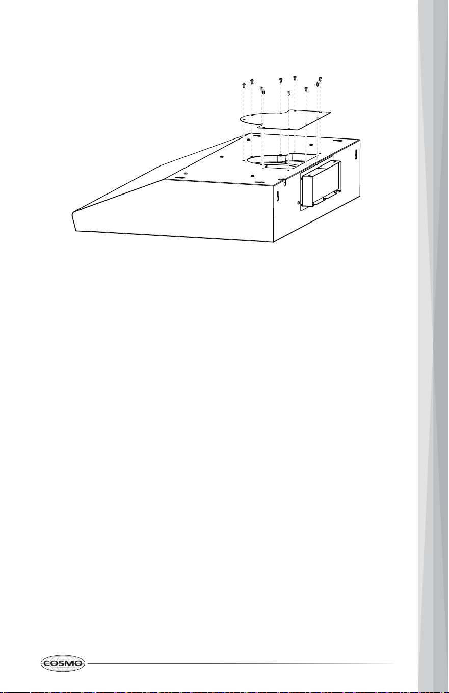
3. Attach the top vent cover using the 4 x 8 mm screws provided.
4. Remove any tape from damper flap if present.
Install Range Hood to Cabinet/Wall
For wall mounting only: Push the range hood toward the wall and
slightly slide the range hood down so that the screws are in the neck of
the slots.
1. Using 2 people, lift range hood into final location. Feed power cord
through the wiring hole in the cabinet bottom.
2. Position the range hood so that the large end of the keyhole slots are
over the mounting screws.
3. For cabinet mounting only: Push the range hood toward the wall so that
the screws are in the neck of the slots. The range hood should be against
the wall.
4. Tighten the mounting screws, making sure mounting screws are in the
narrow neck of the slots.
5. Check that damper, if used, rotates up and down freely.
30
Complete Installation
WARNING ELECTRIC SHOCK HAZARD
• Disconnect power before servicing.
• Replace all parts and panels before operating.
• Plug into a grounded 3-prong outlet.
• Failure to do so can result in death, fire, or electrical shock
1. Connect duct system to hood. Seal joints with clamps to make secure and
airtight.
2. Replace the metal filters. See the "Range Hood Care" section.
3. Reconnect power.
4. Check the operation of the range hood fan and light.
31
Remote Control
RANGE HOOD USE
The range hood is designed to remove smoke, cooking vapors and odors from
the cooktop area. For best results, start the range hood before cooking and
allow it to operate several minutes after the cooking is complete to clear all
smoke and odors from the kitchen.
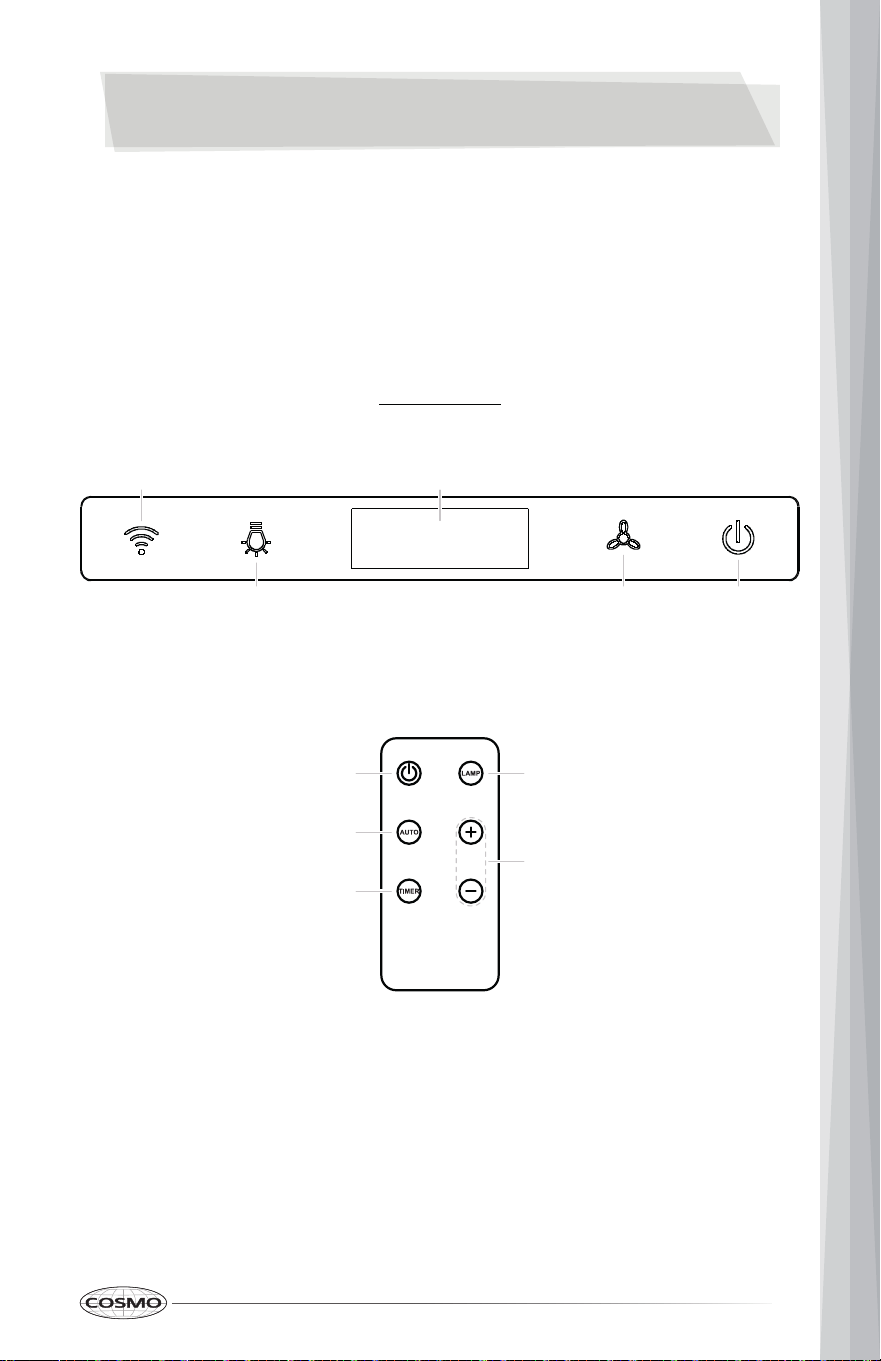
Controls
Range Hood Control Panel
A. Remote Control Signal Receiver
B. Display
C. Light On/Off button
D. Blower speed button
E. Blower power On/Off button
F. Auto turn off button
G. Timer button
A B
C D E
E C
G
D
F

32
Operating the Blower
The Blower Speed button (D) sets the desired speed and control the sound
level for quiet operation. The speed can be changed anytime during fan
operation by pressing the blower speed button repeatedly.
The Blower Power On/Off button (E) turns the blower power on or off.
To turn the blower on
• Press the Blower Power On/Off button (E) and use the Blower Speed
button (D) to set the desired speed.
To turn the blower off
• Press the Blower Power On/Off button (E) once will activate the 3-minute
auto turn off timer, and the blower will turn off automatically after 3
minutes.
• Press the Blower Power On/Off button (E) again will turn off the blower
instantly.
Operating the Light
The Light On/Off button (C) controls both lights. Press once for on and again
for off.
Setting the Clock
1. Press and hold the Blower Power On/Off button (E) for 3 seconds.
2. Press the Light On/Off button (C) or Blower Speed button (D) to adjust the
clock hour.
3. Press and hold the Blower Power On/Off button (E) for 3 seconds.
4. Press the Light On/Off button (C) or Blower Speed button (D) to adjust the
clock minute.
5. Press and hold the Blower Power On/Off button (E) for 3 seconds to save
the clock.
33
RANGE HOOD CARE
Cleaning
IMPORTANT:
• Clean the range hood and metal grease filter frequently according to the
following instructions. Replace metal grease filter before operating range
hood.
• Be sure the power is off/disconnected and the lights are cool before
cleaning the range hood.
Exterior Surfaces
Clean the range hood with a mild detergent and soft cloth. To avoid damage
to the exterior surface, do not use abrasive cleansers or steel-wool pads
Metal Grease Filter
The metal filter should be washed frequently. Place metal filter in dishwasher
or hot detergent solution to clean. Let metal filter dry thoroughly before
replacing it.
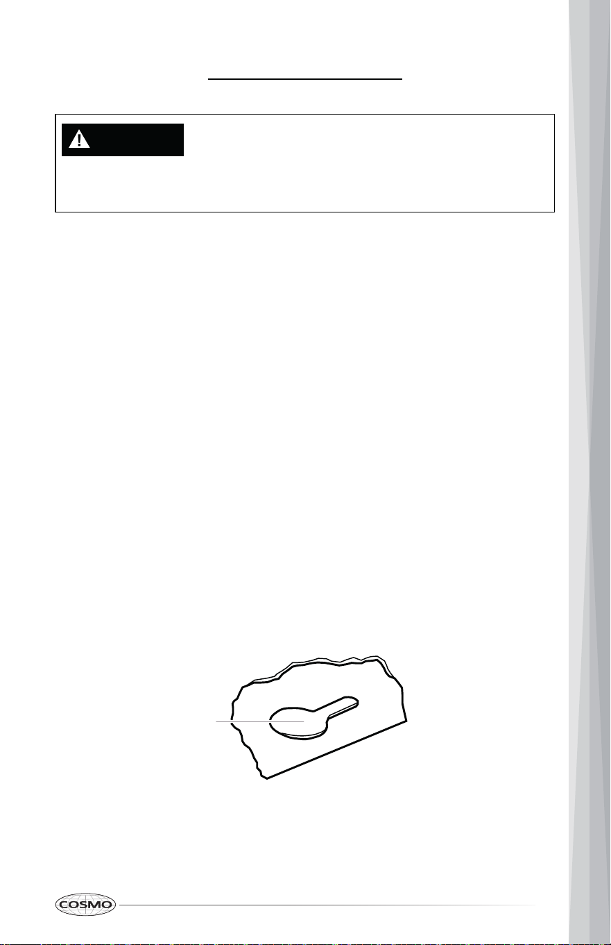
1. Turn off fan and lights. Check that the LED lights are cool.
2. Remove the metal filter by pulling the spring release handle and then
pulling down the metal filter.
3. Wash the metal filter as needed in the dishwasher or hot detergent
solution.
4. Insert the metal grease filter into the upper track. Make sure the spring
release handle is toward the front.
5. Pull the spring release handle down. Push up on the metal filter and
release the handle to latch into place.
34
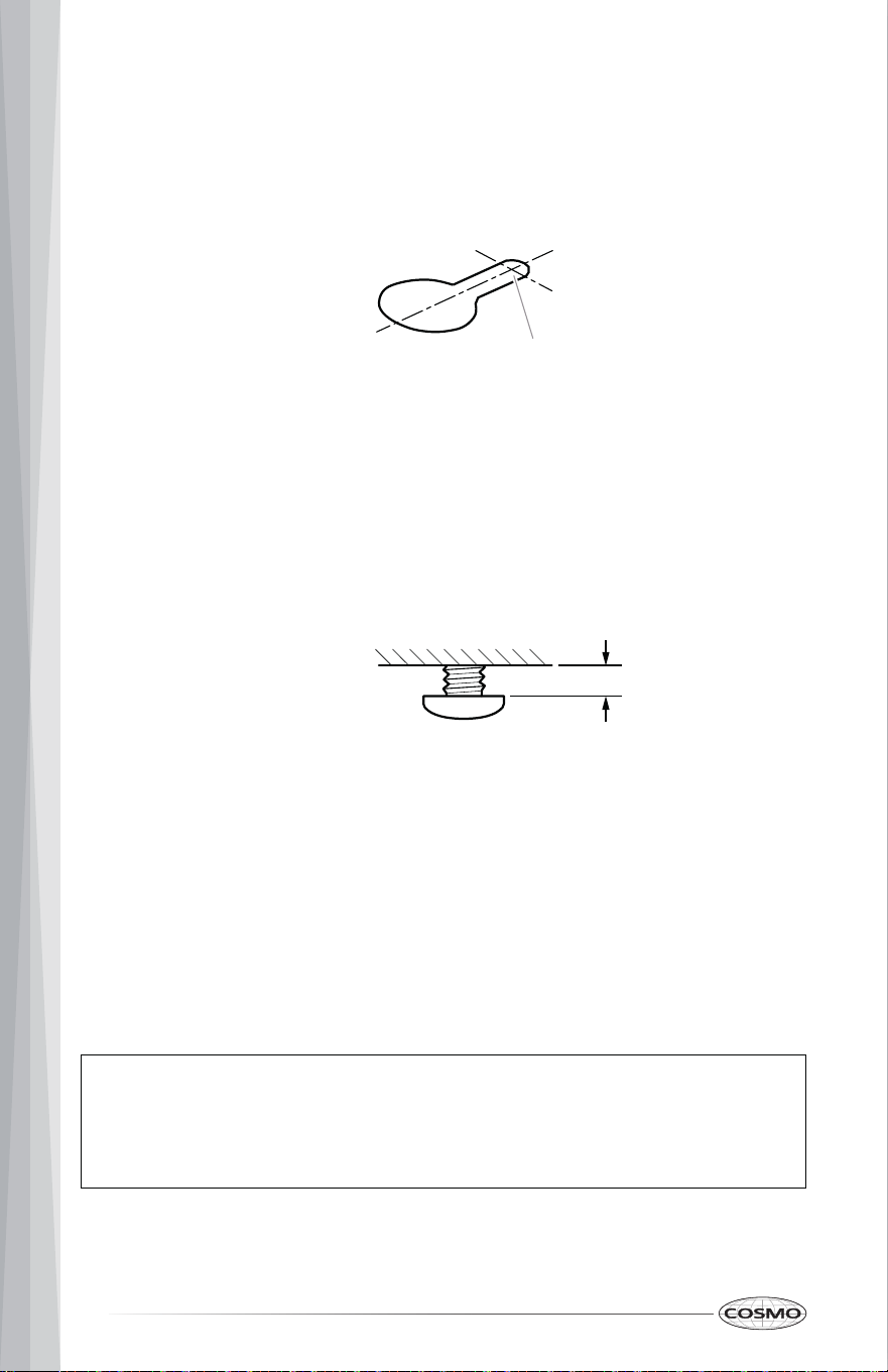
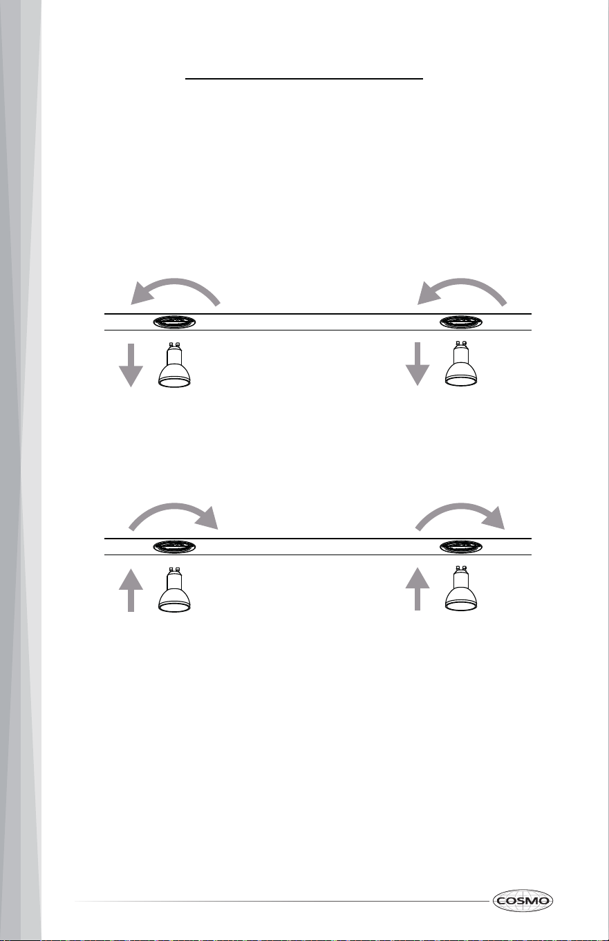
Replacing the LED Light
Turn off the range hood and allow the LED Lights to cool. Replace the LED
lights using tissue or wearing cotton/latex gloves to handle them.
1. Disconnect power.
2. Rotate light counterclockwise to unlock and pull out. Wearing latex gloves
may offer a better grip.
3. Replace with new light of same type, making sure pins are inserted
properly into the sockets of the lamp holder and turn clockwise to lock.
4. Reconnect power.

35
LIMITED WARRANTY
WARRANTY AND SERVICE
TO RECEIVE WARRANTY SERVICE, YOUR PRODUCT MUST BE REGISTERED.
TO REGISTER AND REVIEW FULL WARRANTY DETAILS, VISIT:
WWW.COSMOAPPLIANCES.COM/WARRANTY
SCAN TO REGISTER
CUSTOMER SUPPORT
TO CHAT WITH US LIVE FOR ASSISTANCE, VISIT:
WWW.COSMOAPPLIANCES.COM/CHAT
SCAN TO CHAT
36
Correct disposal of this product:
This marking indicates that this appliance should not be
disposed with other household wastes. To prevent
possible harm to the environment or human health from
uncontrolled waste disposal, recycle it responsibly to
promote the sustainable reuse of material resources.
IMPORTANT
Do Not Return This Product To The Store
If you have a problem with this product, please contact COSMO Customer
Support at
+1 (888) 784-3108
DATED PROOF OF PURCHASE, MODEL #, AND SERIAL # REQUIRED FOR
WARRANTY SERVICE.
IMPORTANT
Ne pas Réexpédier ce Produit au Magasin
Pour tout problème concernant ce produit, veuillez contacter le service des
consommateurs Cosmo Customer Support au
+1 (888) 784-3108
UNE PREUVE D’ACHAT DATEE EST REQUISE POUR BENEFICIER DE LA GARANTIE.
IMPORTANTE
No regrese este producto a la tienda
Si tiene algún problema con este producto, por favor contacte el ayuda al
cliente COSMO al
+1 (888) 784-3108
(Válido solo en E.U.A.)
NECESITA UNA PRUEBA DE DE COMPRA FECHADA, NÚMERO DE MODELO Y DE
SERIE PARA EL SERVICIO DE LA GARANTÍA.

MEMO
MEMO
MEMO