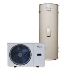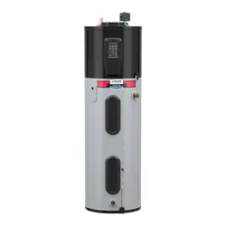
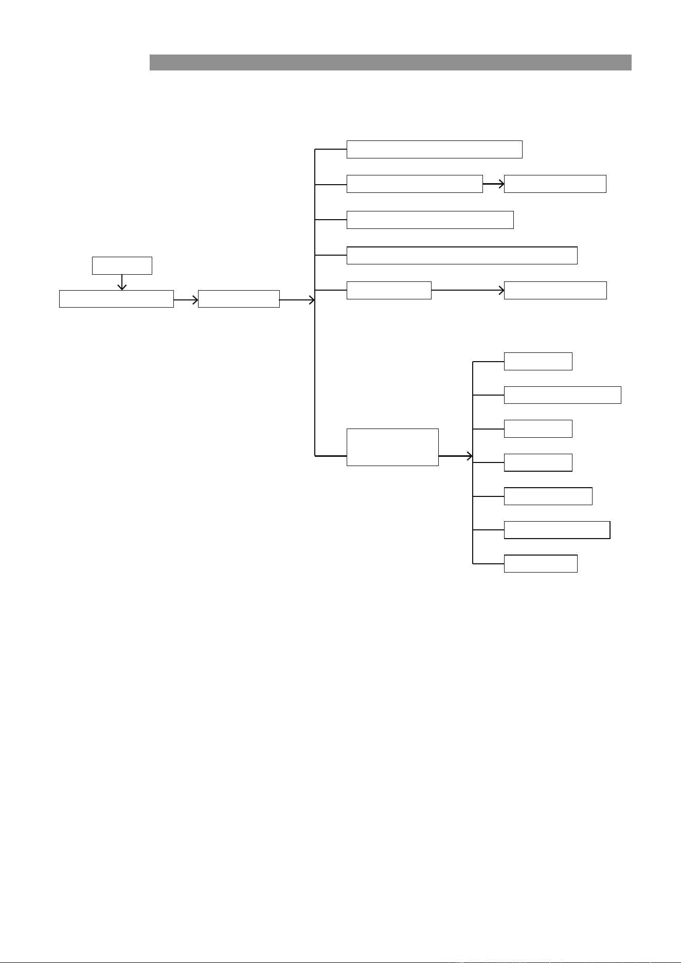
Enviroflo Split - Electric Heat Pump Water Heaters
Operation & Installation Manual
Tank
HPTB250VM24
HPTB315VM24
HPTB400VM24
HPTB250VM24H
HPTB315VM24H
HPTB400VM24H
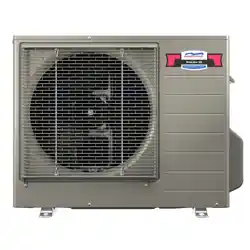
Heat Pump
SHPL70
System
KSHP250M24L70
KSHP315M24L70
KSHP400M24L70
KSHP250M24L70H
KSHP315M24L70H
KSHP400M24L70H
MODELS
Rinnai 2
This appliance must be installed in accordance with:
• Manufacturer’s Installation Instructions
• Current AS/NZS 3500
• Plumbing Code of Australia (PCA)
• Local Regulations and Municipal Building Codes
including local OH&S requirements
This system must be installed, commissioned, serviced,
maintained and removed
These products comply with the lead-free requirements of the
National Construction Code - Volume 3
ONLY by an Authorised Person.
NOT SUITABLE AS A POOL OR SPA HEATER
For continued safety of this appliance it must be installed and
maintained in accordance with the manufacturer’s instructions.
Standard: AS3498:2020
Licence Number: WMK26932
SAI Global
Standard: AS/NZS 2712:2007
Licence Number: SMK1849
SAI Global
Lead Free
Enviroflo Split Heat Pump OIM Issue 1 – MAY 2025

Rinnai 3
TABLE OF CONTENTS
Warnings and Important Information 4
Safety and Regulatory Information .................................................................................................................4
Transport and Storage of Appliance ...............................................................................................................5
Scald Hazards ...................................................................................................................................................6
Operating Principle ..........................................................................................................................................7
System Schematic ............................................................................................................................................7
Safety Devices ..................................................................................................................................................8
Excessive Discharge from Safety Devices ....................................................................................................8
Hydrogen Gas ...................................................................................................................................................9
Anodes .............................................................................................................................................................9
.......................................................................................................9
Turning On the Water Heating System
Turning Off the Water Heating System
...........................................................................................................9
Draining and Filling ..........................................................................................................................................9
Maintenance and Regular Care .......................................................................................................................9
Save a Service Call 10
12
...................................................................................................................................12
Dimensions
System Specifications
.....................................................................................................................................................13
Clearances ......................................................................................................................................................14
Installation 17
OPERATION 24
Regulations and Occupation Health and Safety (OH&S) ............................................................................17
Location ..........................................................................................................................................................17
Water Supply ...................................................................................................................................................18
Storage Temperature .....................................................................................................................................18
Hot Water Delivery Temperature ...................................................................................................................18
Valves and Fittings .........................................................................................................................................18
Transport and Handling .................................................................................................................................19
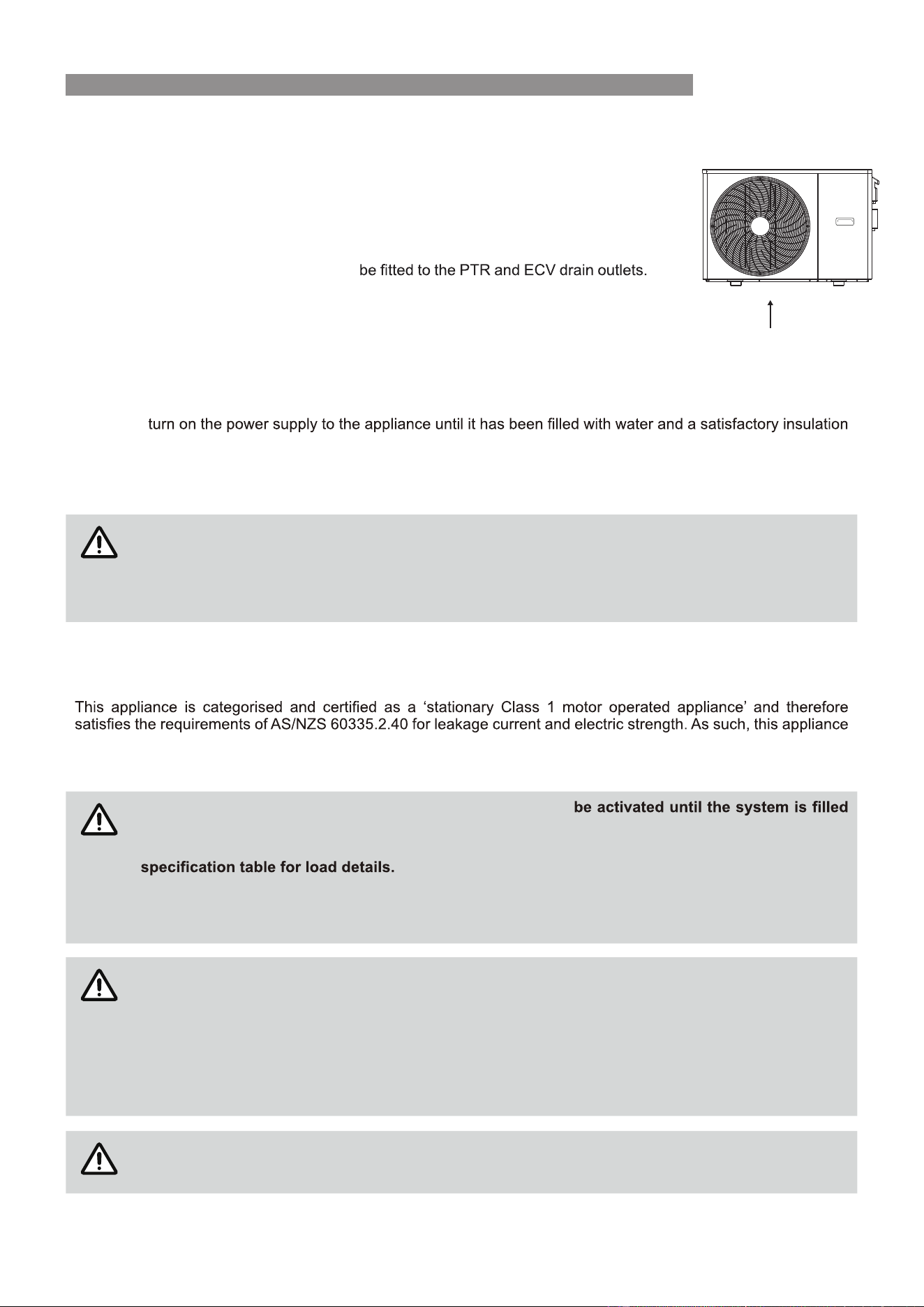
Connect the PTR Valve ..................................................................................................................................20
Plumbing Connections ..................................................................................................................................20
Connect Cold / Hot Water Supply .................................................................................................................20
Connect Condensate Drain line ....................................................................................................................21
Electrical Tests ...............................................................................................................................................21
Electrical Connections ...................................................................................................................................21
Wiring Diagram ...........................................................................................................................................23
Filling The System ......................................................................................................................................23
Commissioning and Finishing the Installation ...........................................................................................23
Operation of Controller
.................................................................................................................................24
Controller Layout and Keys
..........................................................................................................................24
Controller Operation Flow
............................................................................................................................25
Controller Functions and Operation
.............................................................................................................25
Connection of External Signals(Optional)
....................................................................................................27
Wi-Fi Connection
..........................................................................................................................................28
Contacts
32
Enviroflo Split Heat Pump OIM Issue 1 – MAY 2025
Rinnai 4
SAFETY AND REGULATORY INFORMATION
WARNING
DO NOT operate this system before reading the manufacturers instructions.
This appliance must be installed, commissioned and serviced by an authorised person in
accordance with all applicable local rules and regulations.
Access covers of water heating system components will expose 240V wiring and MUST only be
removed by an authorised person.
This appliance is not intended for use by persons (including children) with reduced physical,
sensory or mental capabilities, or lack of experience and knowledge, unless they have been
given supervision or instruction concerning use of the appliance by a person responsible for
their safety.
For continued safety of this appliance it must be installed, operated and maintained in accordance
with the manufacturer’s instructions.
Children should be supervised to ensure they DO NOT play with the appliance.
Care should be taken not to touch the pipe work as it may be HOT!
DO NOT place articles on or against this appliance.
DO NOT
DO NOT operate with collectors or covers removed from this appliance.
DO NOT activate heat pump unless cylinder is full of water.
NEVER
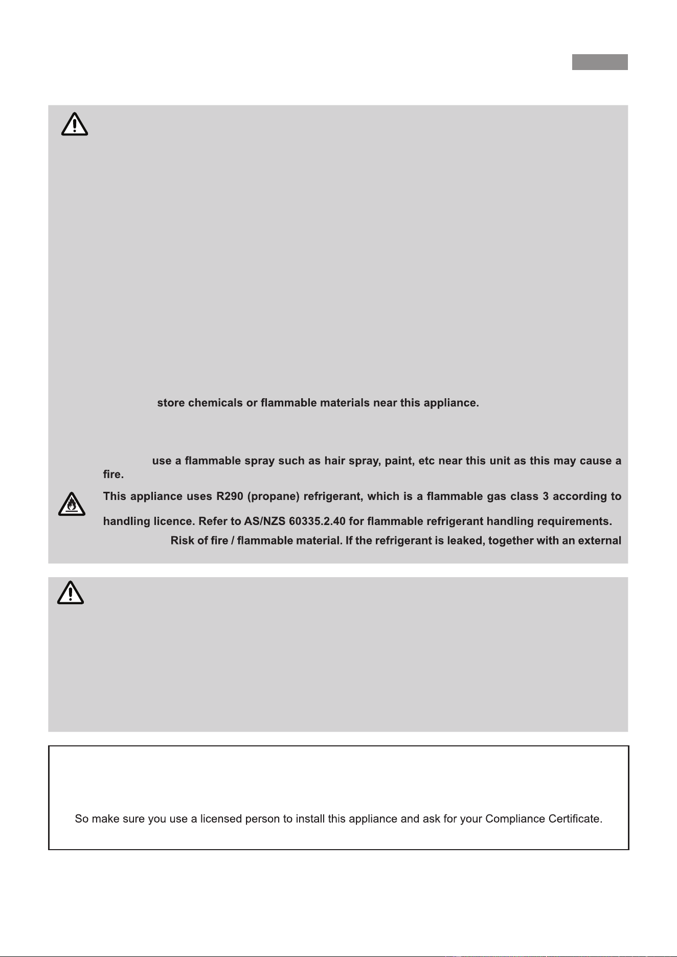
RISK OF FIRE
AS 5149 and MUST be handled by a refrigeration mechanic with appropriate Australian refrigerant
WARNING
ignition source, there is a possibility of ignition.
WARNING
MANDATORY INSPECTION PRIOR TO INSTALLATION
Immediately report any damage or discrepancies to the Supplier of the appliance. This
appliance was inspected and tested at the time of manufacture and packaging, and released for
transportation without known damage. Upon receipt, inspect the exterior for evidence of rough
handling in shipment. Ensure that the appliance is labelled correctly for the gas and electrical
supply, and/or other services it is intended to be connected to.
For safety and warranty purposes, appliances that may be damaged or incorrect MUST NOT be
installed or operated under any circumstances. Installation of damaged or incorrect appliances
may contravene local government regulations. Rinnai disclaims any liability or responsibility
whatsoever in relation to the installation or operation of damaged or incorrect appliances.
NOTICE TO VICTORIAN CONSUMERS
This appliance must be installed by a person licensed with the Victorian Building Authority.
Only a licensed person will have insurance protecting their workmanship.
For further information contact the Victorian Building Authority on 1300 815 127
WARNINGS AND IMPORTANT INFORMATION
The unit is rated at 15 amps (2 core and earth) so the power mains supplying the unit MUST
have a dedicated circuit breaker fitted, if the power supply cable is damaged. it MUST be
replaced by an authorised person in order to avoid a hazard. Take care not to touch the power
connections or plugs with wet hands.
Enviroflo Split Heat Pump OIM Issue 1 – MAY 2025
Rinnai 5
TRANSPORT AND STORAGE OF APPLIANCE
RISK OF FIRE
The appliance(s) shall be stored and transported in an area without ignition sources (for example:
DO NOT pierce or burn the appliance.
Be aware that refrigerants may not contain an odour.
Compliance with AS/NZS 5149 MUST be observed while storing the appliance.
IMPORTANT
National and state regulations exist for storage, handling and transport of hazardous goods
of the equipment, permitted to be transported or stored together will be determined by the
applicable regulations.
IMPORTANT
IMPORTANT
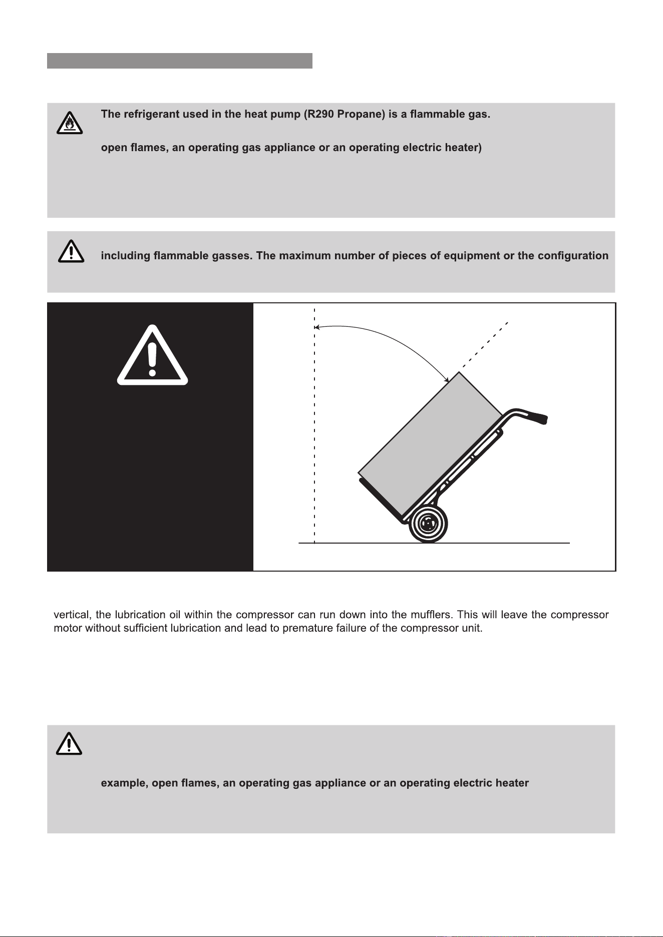
DO NOT TILT
MORE THAN 45°
FROM VERTICAL
45°
The Rinnai Electric Heat Pump must be transported at an angle no greater that 45º from vertical. As the compressor
unit is located at the top of the electric heat pump, should the heat pump be tilted at a greater angle than 45º from
Tilting the system beyond 45º from vertical will also place undue strain on compressor motor mounts and associated
piping.
WARNING
Do not use means to accelerate the defrosting process or to clean, other than those recommended
by the manufacturer.
The appliance shall be stored in a room without continuously operating ignition sources. For
.
Do not pierce or burn.
Be aware that refrigerants may not contain an odour.
WARNINGS AND IMPORTANT INFORMATION
As a aeneral good practice it is better to keep the compressor upright as much as possible to avoid any risks.
Retumning the Rinnai Electric Heat Pump to a vertical position will not allow the oil to properly flow back into
thecompressor motor.
Enviroflo Split Heat Pump OIM Issue 1 – MAY 2025
Rinnai 6
SCALD HAZARDS
HOT WATER CAN CAUSE SCALDS.
CHILDREN, DISABLED, ELDERLY AND THE INFIRM ARE AT THE HIGHEST RISK OF
BEING SCALDED.
FEEL WATER TEMPERATURE BEFORE BATHING OR SHOWERING.
SCALDS FROM HOT WATER TAPS CAN RESULT IN SEVERE INJURIES TO YOUNG
CHILDREN.
SCALDS OCCUR WHEN CHILDREN ARE EXPOSED DIRECTLY TO HOT WATER WHEN
THEY ARE PLACED INTO A BATH WHICH IS TOO HOT.
ALWAYS......
Test the temperature of the water with your elbow before placing your child in the bath, also carefully
feel water before bathing or showering yourself.
Supervise children whenever they are in the bathroom.
CONSIDER.....
Installing child proof tap covers or child resistant taps (both approaches will prevent a small hand being
able to turn on the tap).
Installing tempering valves or thermostatic mixing valves which reduce the hot water temperature
your installer or local plumbing authority if in doubt.
NEVER….
Leave a toddler in the care of another child. They may not understand the need to have the water
temperature set at a safe level.
WARNINGS AND IMPORTANT INFORMATION
Enviroflo Split Heat Pump OIM Issue 1 – MAY 2025
Rinnai 7
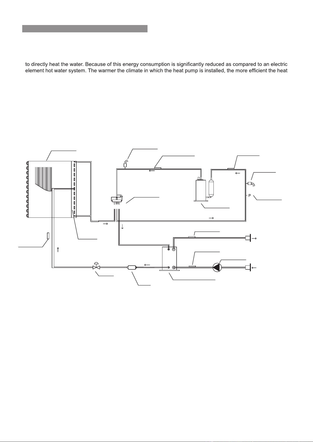
OPERATING PRINCIPLE
The operation of an electric heat pump is very similar to a refrigerator, but in reverse. A heat pump operates by
transferring heat from the ambient outside air into the water. Electricity is just used to operate the system, but not
pump system will be at heating water.
The heat pump unit includes a circulation pump which draws water from the bottom of the storage tank and
returns it to the tank at a higher temperature. A temperature sensor in the tank is used to control the heat pump
operation to achieve suitable tank temperature.
During the occasional times when the ambient weather conditions are not suitable for the heat pump to operate,
the electric element will provide heating to ensure a supply of hot water.
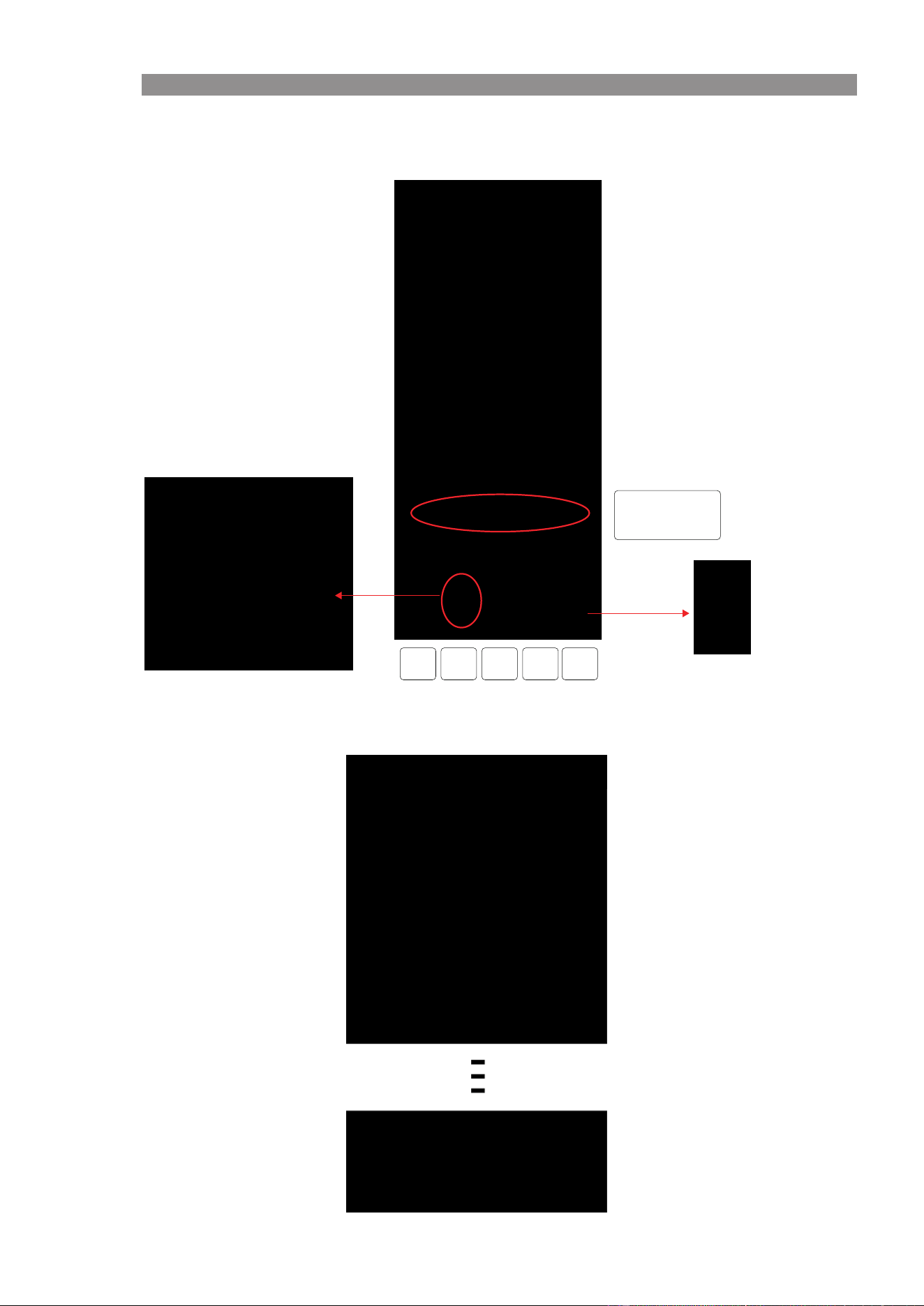
SYSTEM SCHEMATIC
WARNINGS AND IMPORTANT INFORMATION
Compressor
Sunction temp.sensor
Water outlet sensor
Water inlet sensor
4-way valve
Coil temp. sensor
EEV
Filter
Plate heat exchanger
Circulation pump
Hot water outlet
Cold water inlet
Discharge temp. sensor
Ambient
temp.sensor
Schrader valve
High pressure switch
Low pressure switch
Evaporator
ESC
Enviroflo Split Heat Pump OIM Issue 1 – MAY 2025
Enviroflo Split Heat Pump OIM Issue 1 – MAY 2025Rinnai 8
SAFETY DEVICES
The water heating system is supplied with various safety devices including temperature sensors, overheat sensors
and switches and a Pressure & Temperature Relief (PTR) valve. These devices must not be tampered with or
order.
WARNING
DO NOT tamper with or remove safety devices.
DO NOT .
DO NOT block or seal the PTR Valve and drain pipe.
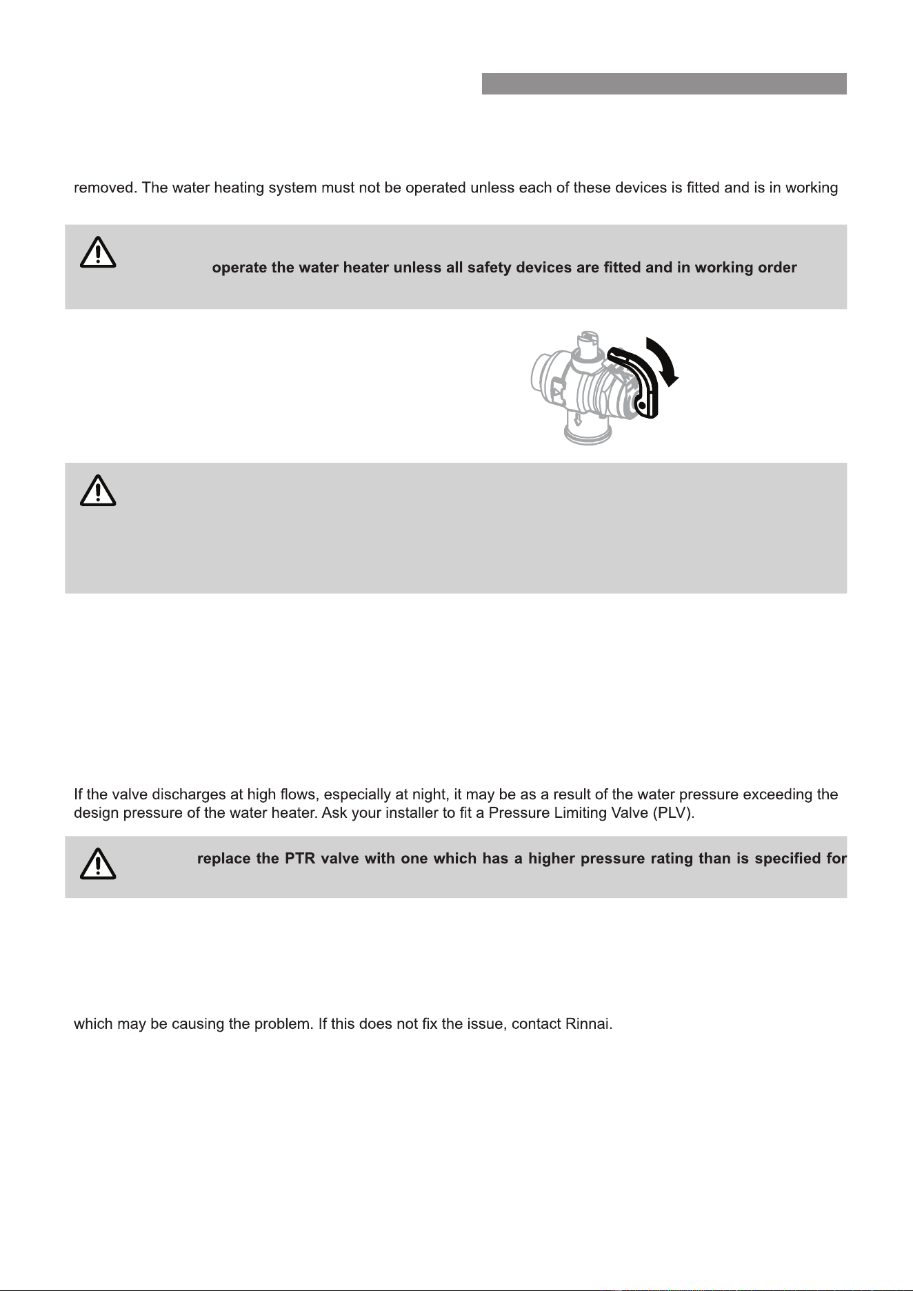
Pressure & Temperature Relief (PTR) Valve
This valve is located near the top of the water heater and is
essential for safe operation. It is normal for the valve to release
a small quantity of water through the drain line during heating.
However, continuous leakage of water from the valve and its
drain line may indicate a problem with the water heater.
WARNING
NEVER block the outlet of the PTR valve or it’s drain line for any reason. The easing gear MUST
be operated at least every 6 months to remove lime deposits and verify that it is not blocked.
Failure to do this may result in the water heater failing.
If the valve does not discharge water when the easing gear lever is opened, or does not seal again
when the easing gear is closed, attendance by an authorised person MUST be arranged without
delay. The PTR valve is not serviceable.
EXCESSIVE DISCHARGE FROM SAFETY DEVICES
Pressure & Temperature Relief (PTR) Valve
It is normal and desirable that this valve allows a small quantity of water to be discharged during the heating cycle.
If it discharges more than a bucket of water during a 24 hour period or discharges continuously there may be
another problem.
If the valve dribbles continuously, try easing the valve gear for a few seconds as described above. This may
dislodge any foreign matter and alleviate the problem.
WARNING
NEVER
your water heater.
Expansion Control Valve (ECV) - if required
It is normal that this valve allows a small quantity of water to be discharged during the heating cycle. If it discharges
more than a bucket of water during a 24 hour period or discharges continuously there may be another problem.
If the valve leaks continuously, try easing the valve gear for a few seconds. This may dislodge any foreign matter
Operate the easing gear regularly to remove any lime deposits and to verify that it is not blocked.
Lift lever until water
flows fromdrain line
(Lower lever gently!)
WARNINGS AND IMPORTANT INFORMATION
Enviroflo Split Heat Pump OIM Issue 1 – MAY 2025Rinnai 9
HYDROGEN GAS
may accumulate in the water heater. To dissipate this safely, it is recommended that a non electrically operated
hot tap be turned on for two minutes at a sink, basin, or bath, but not a dishwasher or other appliance. During
discharged through the tap, it will probably make a sound like air escaping.
ANODES
cylinder. The life of the water heater may be extended by arranging for an authorised person to inspect the anodes
and replace them as required. It is recommended that the anodes be inspected at least every 5 years. The factory
(TDS) content in the water supply does not exceed 600 mg/L, (which is the case in most areas). In areas where
the total dissolved solids (TDS) content in the water supply exceeds 600 mg/L Rinnai aluminium based anodes
are required.
TURNING OFF THE WATER HEATING SYSTEM
If you plan to be away for only a few nights, we suggest you leave the water heating system switched on. If it is
necessary to switch off the water heater, do so as outlined below:
WARNING
DO NOT
and freezing conditions are expected, the water needs to be drained from the heat pump unit.
Follow the procedure described below in the section ‘Draining and Filling’.
TURNING ON THE WATER HEATING SYSTEM
Switch on the electric supply to the heat pump unit. Water heating will now occur as required. It may take a number
of hours before hot water is available.
DRAINING AND FILLING
out by an authorised person.
Draining water from the heat pump unit is necessary if the power will be shut off to the unit and snow or frost
conditions are expected. Arrange for an authorised person to carry out this task.
To drain the heat pump:
1. Turn off power to the heat pump.
2. Close the cold water mains supply stop cock.
3. Open a hot tap to relieve pressure.
4. Disconnect the hot outlet near the top of the storage cylinder.
5. Disconnect the cold inlet near the bottom of the storage cylinder.
6. The system will now drain completely.
MAINTENANCE AND REGULAR CARE
on page 8.
checked to ensure there are no blockages.
WARNING
DO NOT
the outer skin of the tank may damage the heat exchanger. Rinnai’s warranty will not cover any
resultant faults.
WARNINGS AND IMPORTANT INFORMATION
Enviroflo Split Heat Pump OIM Issue 1 – MAY 2025Rinnai 10
Rinnai’s servicing network personnel are fully trained and equipped to give the best service on your Rinnai
appliance. If your appliance needs service, ring one of the service contact numbers on the back of this booklet.
If the power supply cord to the heat pump unit is damaged, they must be replaced by an authorised person in order
to avoid a hazard.
Use the following guide to avoid the need for an unnecessary service call.
INSUFFICIENT OR NO HOT WATER
Heat Pump Unit Not Powered Check to ensure the electric isolating switch at the
switchboard (usually marked “Hot water” or “Water
heater” is turned on. (note that the compressor will not
start up for 2 minutes after power is turned on).
Excessive hot water consumption Often end users are surprised at the amount of hot water
used, especially when showering. If the amount of hot
water used during the day exceeds the storage capacity
Pressure & Temperature Relief (PTR) Valve
continually discharging water
It is normal and desirable that this valve allows a small
quantity of water to be discharged during the heating
cycle. If it discharges more than a bucket of water during
a 24 hour period or discharges continuously there may be
another problem.
If the valve dribbles continuously, try easing the valve gear
for a few seconds as described in the section ‘Excessive
Discharge from Safety Devices’ on page 8. This may
dislodge any foreign matter and alleviate the problem.
it may be as a result of the water pressure exceeding the
design pressure of the water heater. Ask your installer to
Expansion Control Valve (ECV) continually
discharging water
It is normal and desirable that this valve allows a small
quantity of water to be discharged during the heating
cycle. If it discharges more than a bucket of water during
a 24 hour period or discharges continuously there may be
another problem.
If the valve leaks continuously, try easing the valve gear
for a few seconds as described in the section ‘Excessive
Discharge from Safety Devices’ on page 8. This may
dislodge any foreign matter and alleviate the problem. If
this does not alleviate the problem contact Rinnai.
Ambient conditions too hot To protect the components of the heat pump unit it may
not operate when the ambient temperature is higher than
45°C. Please switch to ELECTRIC mode if water heating
is required.
Ambient conditions too cold To protect the components of the heat pump unit it may
not operate when the ambient temperature is less than
-10°C. Please switch to ELECTRIC mode if water heating
is required.
NO WATER FROM THE TAP
Restriction in the hot tap or failure of the cold
water supply to the water heater
water isolation valve is fully open.
SAVE A SERVICE CALL
Enviroflo Split Heat Pump OIM Issue 1 – MAY 2025Rinnai 11
HIGH ELECTRICITY BILLS
Excessive hot water consumption
The electricity tariff will determine the running costs
of the system. It is important the end user is aware of
the applicable tariffs. Contact your electricity supplier to
Higher Element Usage In extremely cold conditions the element may be operating
more than normal.
WATER FLOW FLUCTUATIONS
One or more hot taps opened at the same
time
More than one or two hot taps in use at the same time
Is there more than one or two hot taps open, or are
appliances such as a dishwasher or washing machine, in
use at the same time?
Ensure only one or two hot taps are on at one time.
WATER HAMMER
Hot and cold water plumbing in the premises Have a plumber check clipping of hot and cold water
pipe work and install a pressure limiting valve and water
hammer arrestor as required.
HEAT PUMP ICES UP
Defrosting function The heat pump has a built in hot bypass defrosting
function which may operate and remove any ice.
HEAT PUMP ERROR INDICATOR*
Error
LP SW Err
HP SW Err
Coil Temp Err
Discharge Temp Err
Suction Temp Err
Tank Temp Err
Ambient Temp Err
Outlet Temp Err
Inlet Temp Err
DC Fan Err
High Discharge temp
Invertor Err
* If an error code is displayed on the control unit please contact Rinnai Customer Care Immediately.
Error Description
Low pressure switch protection
High pressure switch protection
Coil temperature sensor fault
Discharge temperature sensor fault
Suction temperature sensor fault
Tank temperature sensor fault
Ambient temperature sensor fault
Water outlet temperature sensor fault
Water inlet temperature sensor fault
DC Fan motor fault
Discharge temperature too high
Compressor Invertor fault
Possible Causes
Pressure switch is broken/Connection is loose/EEV
fault/Refrigeration system is blocked/Refrigerant is less.
Pressure switch is broken/Connection is loose/EEV
fault/Refrigeration system is blocked/Water pump is broken
Sensor fault/Connection is loose
Sensor fault/Connection is loose
Sensor fault/Connection is loose
Sensor fault/Connection is loose
Sensor fault/Connection is loose
Sensor fault/Connection is loose
Sensor fault/Connection is loose
DC Fan motor fault is broken/Connection is loose
Lack of refrigerant/system leak
Main PCB fault/Compressor connection is
loose/Compressor fault
SAVE A SERVICE CALL
Enviroflo Split Heat Pump OIM Issue 1 – MAY 2025Rinnai 12
HEAT PUMP SPECIFICATIONS
Model
Net Weight 66kg
1047x375x690mmDimensions (L×D×W)
Ambient Temperature Limits
(for heat pump operation - element will
operate beyond these limits)
-10°C to 45°C
Ingress Protection
Heat pump - Hot Outlet and Cold inlet
IPX4
Connections
ISO 7.1 ¾” RC
Storage Cylinder - PTR Valve Connection ISO 7.1 ½” Rp
Pressure & Temperature Relief (PTR) Valve
(Supplied) Setting / Rating
1000 kPa / 10kW
ECV Fitted
Fit PLV if mains
pressure exceeds
680 kPa
Recommended PLV
pressure rating
500 kPa
ECV Not Fitted
Fit PLV if mains
pressure exceeds
800 kPa
Recommended PLV
pressure rating
500 kPa
Rated Input Electric Element
(Factory Wired)
2.4 kW
Maximum Input Refrigeration Module
(Factory Wired)
2.0 kW
Total Maximum Input
Maximum Energy Output
2.4 kW
(Use to size PTR)
7.8 kW
Power Supply 220V-240V AC/50 Hz.
Switchboard Power Circuit In accordance with AS/NZS 3000 and local regulations
Maximum Current 11.5 Amps (15 Amps rating power supply)
Sound Pressure Level* 45 ~ 52 dB(A)
Refrigerant Type / Mass R290 / 510 g
Refrigerant Circuit Maximum Pressure 3200 kPa
Performance (COP)
32.6°C Ambient
21.1°C cold water inlet
9.2
Heat Output
32.6°C Ambient
21.1°C cold water inlet
7.0kW
structures.
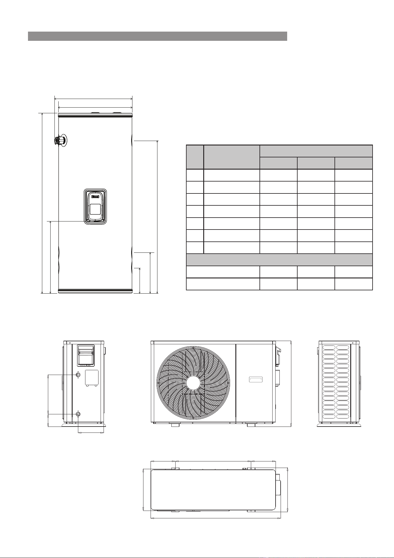
SPECIFICATIONS
SPECIFICATIONS
SHPL70
Enviroflo Split Heat Pump OIM Issue 1 – MAY 2025Rinnai 13
SPECIFICATIONS
INLETS
OUTLETS
C
B
D
E
F
G
A
Dimension (mm)
Tank Height
Width
Tank Diameter
Hot Water Outlet
Heat Pump Hot Flow
Cold Water Inlet
Electric Cover
Net Weight (kg)
Filled Weight (kg)
Tank Weights (kg)
No
A
B
C
D
E
F
G
Tank Model
HPTB315
1770
674
605
1541
332
210
754
77
413
HPTB250
1477
674
605
1248
332
210
593
66
341
HPTB400
1840
744
675
1587
359
237
793
90
514
DIMENSIONS (mm)
Heat Pump
101 316
206.5
610
197.5197.5
335
1046.5
375
689.8
Tank
Enviroflo Split Heat Pump OIM Issue 1 – MAY 2025Rinnai 14
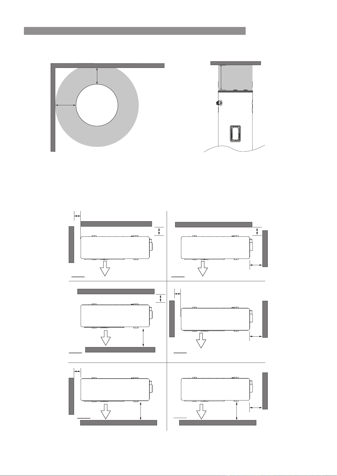
SPECIFICATIONS
CLEARANCES
Tank
Heat Pump
Allow 600mm on the fan discharge side and 100 mm clearance on the fan suction side to allow for sufficient air flow
through the fan.All measurements outlined below are minimums.
Minimum
150 mm at
side
100 mm Minimum at rear
TANK
Minimum 300 mm
Front
Front
Front
Front
Front
Front
100mm MIN
100mm MIN
600mm MIN
600mm MIN 600mm MIN
600mm MIN
600mm MIN
600mm MIN
100mm MIN
100mm MIN
100mm MIN
100mm MIN
Enviroflo Split Heat Pump OIM Issue 1 – MAY 2025Rinnai 15
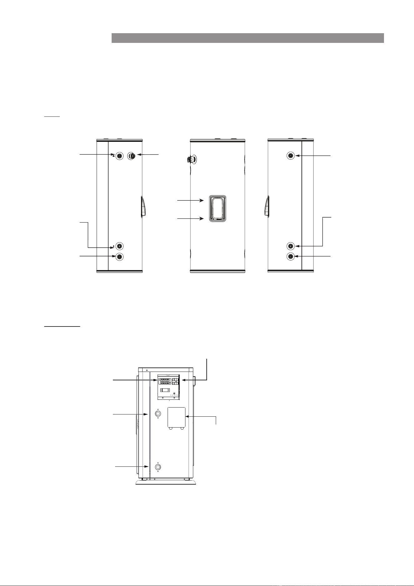
SPECIFICATIONS
CONNECTIONS
The Tank is supplied with duplicate connections on either side so that the Heat Pump unit can be located on the
Left (A) or Right (B) side of the tank more easily as required.
Hot Outlet (A)
Hot Water from
Heat Pump (A)
PTR
Upper Tank
Sensor
Element
Tank
Hot Outlet (B)
Hot Water from
Heat Pump (B)
Cold Supply to
Heat Pump (A)
/ Cold Supply
from Mains
Cold Supply to
Heat Pump (B)
/ Cold Supply
from Mains
Left Side Connections Front
Right Side Connections
Hot Water Outlet
to The Tank
Dry contact
Controller box
Power supply to Heat Pump
Tank element power supply
Cold Water Supply
to The Heat Pump
Heat Pump
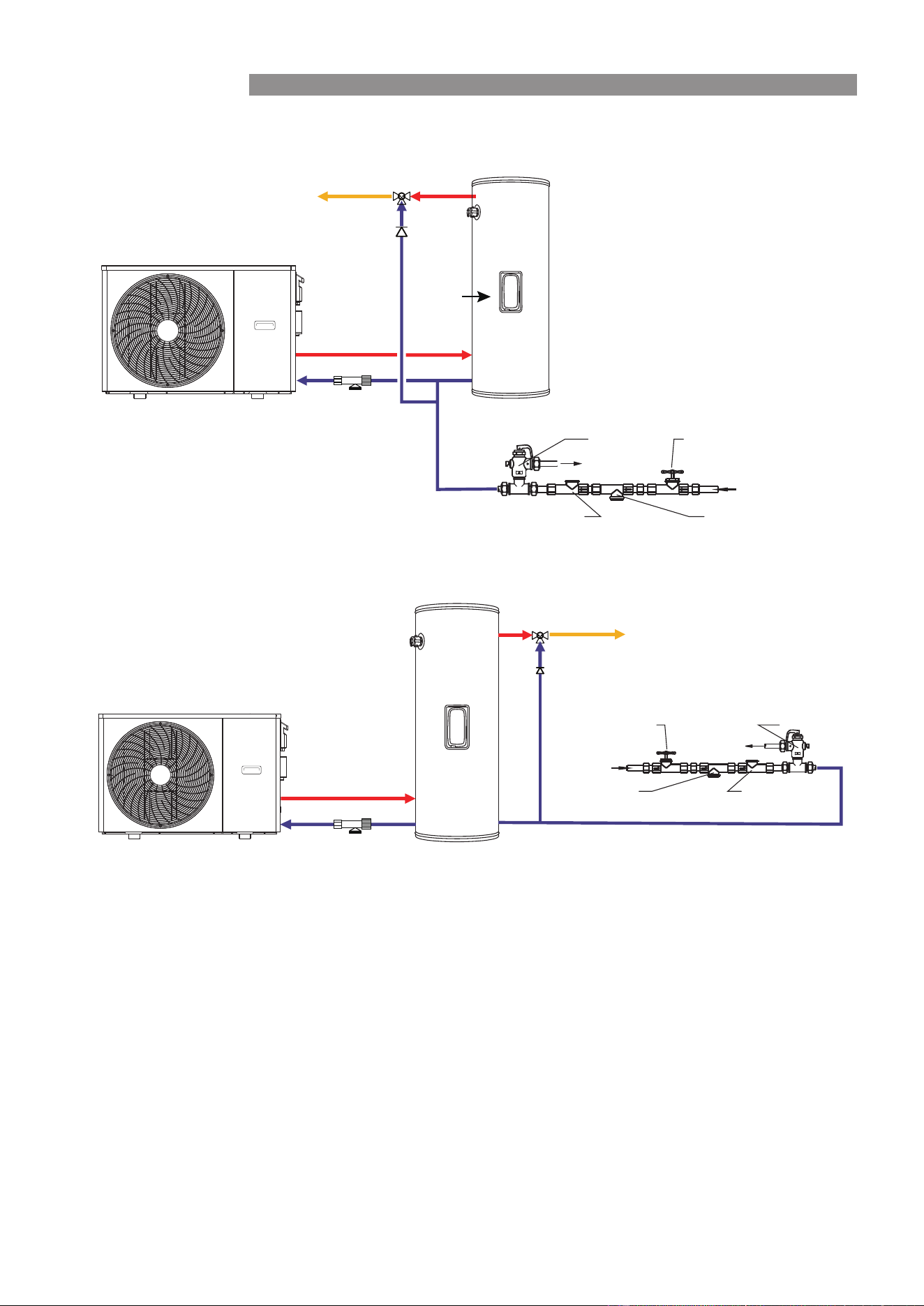
SPECIFICATIONS
SYSTEM SCHEMATIC
Typical Example 1
Typical Example 2
Hot Water to Residence
Tempering Valve
Hot Water Return from
Heat Pump
Hot Water Return from
Heat Pump
Cold Supply to Heat Pump
Cold Supply to Heat Pump
Strainer
Strainer
³/4"
³/4"
³/4"
³/4"
Tank
Element
PTR
Drain
Non-return Valve Line Strainer
Cold Water Inlet
Isolating Valve (Spindle Vertical)
Cold water expansion
control valve
Hot Water to Residence
Tempering Valve
Drain
Non-return ValveLine Strainer
Cold Water Inlet
Isolating Valve (Spindle Vertical)
Cold water expansion
control valve
Enviroflo Split Heat Pump OIM Issue 1 – MAY 2025Rinnai 16
Enviroflo Split Heat Pump OIM Issue 1 – MAY 2025Rinnai 17
REGULATIONS AND OCCUPATION HEALTH AND SAFETY
(
OH&S
)
WARNING
Installation and commissioning MUST be performed by authorised persons.
The heat pump MUST be installed in accordance with these instructions and all regulatory
requirements which exist in your area including those in relation to manual lifting.
Applicable publications and regulations may include:
•
AS/NZS 3500 National Plumbing and Drainage
•
AS/NZS 3000 Wiring Rules
•
Building Codes of Australia (BCA)
•
Local Occupational Health and Safety (OH&S) regulations
This appliance is not suitable for use as a domestic spa pool or swimming pool heater.
Electric Heat pumps are heavy and bulky items. Australian States and Territories have a Principal
Occupational Health and Safety (OH&S) Act which contains requirements relating to the handling
of large, bulky or awkward items. Persons installing heat pump systems MUST be aware of
requirements.
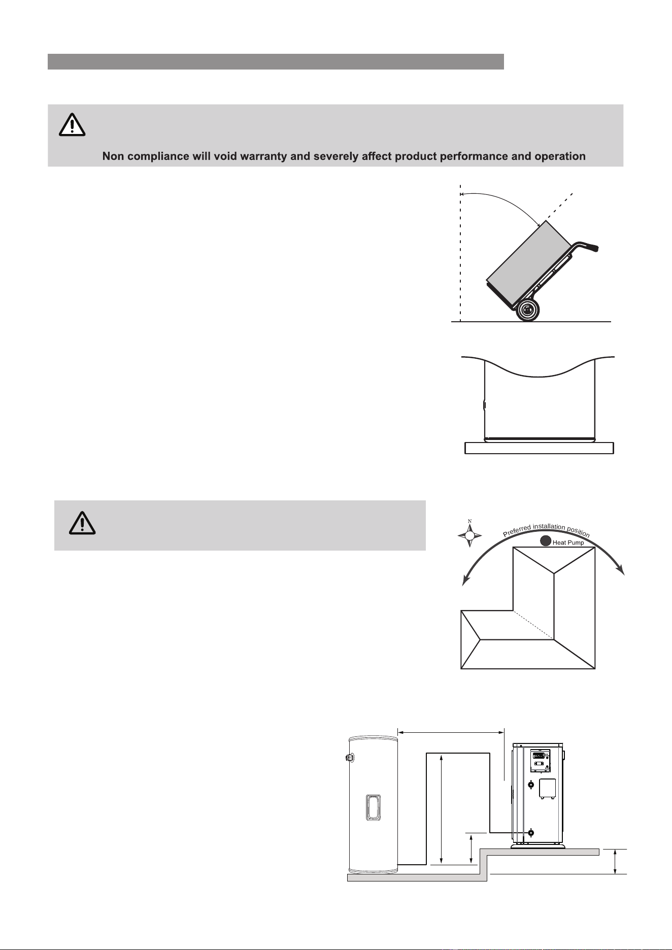
LOCATION
The electric heat pump can be installed externally or internally.
The electric heat pump should be placed as close as practicable to the most frequently used hot water outlet point
or points to minimise the delay time for hot water delivery. This will usually be the kitchen tap. For installations
used which minimise the waiting time for hot water delivery. We recommend not to install the unit close to where
operational sound levels may cause occupant disturbances, such as bedrooms.
repair or replacement access.. The heat pump MUST be installed in a vertically upright position. All components
MUST be accessible without the use of a ladder or scaffold. The unit MUST NOT be installed in roof spaces.
WARNING
Ensure the location complies with the requirements of AS/NZS 60335.2.40 & AS/NZS 5149.
The air inlet and outlet of the heat pump module MUST be away from areas with strong wind and MUST be
on page 14.
The heat pump MUST be connected to an independent AC 240 V, 50 Hz power supply, Dedicated Safety Switch
Circuit Breaker and Weatherproof Isolating Switch
and are accessible for service and removal. The information on the rating plates MUST also be readable.
The heat pump MUST be installed free-standing on a level and stable base. The cylinder should be mounted on a
concrete base at least 50mm thick or on well-seasoned, evenly spread hardwood slats with a thickness of at least
25mm. Where property damage can occur as a result of water leakage, the storage cylinder MUST be installed
DOES NOT
stand on wet surfaces.
Internal Installation
For internal installations the area MUST meet the following requirements:
•
•
•
If the heat pump is installed internally careful consideration should be taken in regards to positioning and limiting
Minimum room volume of 75m
3
per unit.
Good Ventilation (i.e minimum 500 L/s per unit)
Away from any ignition sources or corrosive environments.
the effect of unit noise and reverberation during operation, which may cause noise disturbances otherwise.
INSTALLATION
Enviroflo Split Heat Pump OIM Issue 1 – MAY 2025Rinnai 18
Condensation
formation, the condensate outlet will need to be plumbed to a suitable drain.
Drainage
Where property damage can occur as a result of water leakage, the water heater MUST be installed with a safe
MUST comply with local
regulatory requirements and. AS/NZS 3500.4 also requires the use of a safe tray for particular situations.
WATER SUPPLY
This appliance is intended to be permanently connected to the water mains and not to be connected by a hose set.
The maximum water pressure is listed on page 12. An approved pressure limiting valve may be required if the
maximum rated water supply pressure is exceeded.
Water chemistry and impurity limits are detailed in the separate warranty document. Most metropolitan water
supplies fall within these requirements. If you are unsure about water quality and suitability, contact your water
authority.
MUST
In a scaling water supply, calcium carbonate and possibly other compounds are deposited out of the water onto
any hot metallic surface and form a scale. Scaling water may cause scale deposits to form onto the metallic
surfaces of the PTR valve and may prevent it from operating properly. To prevent this, an expansion control valve
(ECV) MUST MUST
STORAGE TEMPERATURE
If the tank water temperature is set below 60°C, the system will automatically override this setting once a week to
activate the disinfection cycle, heating the water to 60°C to meet regulatory requirements. This setting can not be
altered.
HOT WATER DELIVERY TEMPERATURE
This appliance may deliver water at high temperature. Refer to the Plumbing Code of Australia (PCA), local
requirements and installation instructions to determine if additional delivery temperature control is required.
The PCA, local regulations and the requirements of AS/NZS 3500.4 MUST be considered regarding the
temperature limitations of hot water supplied to areas used primarily for personal hygiene.
The temperature of water to certain areas is limited to different temperatures according to purpose, for e.g. early
childhood centres, primary and secondary schools and nursing homes or similar facilities for young, aged, sick
or people with disabilities and for all other buildings. To comply with these requirements, a temperature limiting
device, such as a thermostatic mixing or tempering valve, will be required on hot water systems.
VALVES AND FITTINGS
IMPORTANT
A 10 kW capacity, combined Pressure and Temperature Relief (PTR) valve is supplied with the
•
A cold water expansion control valve (ECV). An ECV MUST
to the cold water supply to the storage cylinder to comply with local regulations. An ECV is recommended in
all other geographical areas where the water supply has a tendency to cause scaling. This will reduce hot
water discharge from the pressure and temperature relief (PTR) valve which minimises wear on this valve.
•
A stop cock, non return valve and line strainer. Combination valves incorporating two or more of these
by the installer.
•
Cold water supply and hot water discharge pipework to and from the storage cylinder. This pipework MUST
•
An approved pressure limiting valve (supplied with some systems) is required if the maximum rated water
supply pressure on page 12 is exceeded.
•
Tempering valve(s) or thermostatic mixing valve
INSTALLATION
Enviroflo Split Heat Pump OIM Issue 1 – MAY 2025Rinnai 19
TRANSPORT AND HANDLING
IMPORTANT
When moving the unit, it MUST be close to vertical at all times.
When using a trolley to move the unit, ensure it is not tilted more than 45° from the vertical.
45°
Never tilt unit more than 45˚ from vertical
The Rinnai Electric Heat Pump MUST be transported at an angle no greater that 45° from vertical.
It is essential that the tank remains in an upright position at all times during transportation.
Transporting the tank while lying flat may cause internal components, particularly the anode, to
become damaged. The anode plays a critical role in protecting the tank from corrosion, and any
damage to it could compromise the performance and longevity of the unit. Always ensure the tank
is securely positioned upright to maintain product integrity.
Arrive at site and conduct a safety audit. Safety audits can also be known as Work Method
Statements (WMS) or Job Site Analysis (JSA).
Park your vehicle as close as allowable to your installation. Unload all materials in a safe manner.
Position all materials in a convenient position near the work area.
Where the requirements for internal installation can't be met, the heatpump MUST be installed
outdoors.
The location MUST consider noise impact on living areas. Avoid positioning near bedrooms or
neighbours’ bedrooms. Although the running noise level is very low it can be expected that the heat
pump will run during the night.
Adequate access MUST be available to the relief valve and anodes.
Safely position the new unit on a level surface in accordance with all plumbing and building regula-
tions.
A properly drained overflow tray MUST be used where property damage could occur from water
spillage.(See AS/NZS 3500.4.2 for further details.)
Allow 200m³ of free space surrounding the unit. This provides clear ambient airflow assisting the
product's performance. Ensure the clearance requirements specified in the section 'Dimensions'
on page14 are complied with. The area MUST also be clear of debris such as leaves and tree
branches.
Pipework must have no more than six bends in total between the
tank and the heat pump.
Piping Height – Cold Water Inlet (1)
The cold water inlet on the heat pump must be installed no more than
1 meter above the tank outlet.
Right-Angle Loop (2)
If a right-angle loop is used, it must be within 1 meter in total height and
be present in only one location.
Overall Height Difference (3)
The total vertical height difference between the heat pump and the tank
must not exceed 1 meter.
Horizontal Distance (4)
The maximum distance between the tank and the heat pump must not
exceed 5 meters.
Base Requirement
Both the heat pump and storage tank must be installed on level and
stable bases to ensure proper operation and to prevent vibration or
stress on pipe connections.
POSITIONING THE HEAT PUMP
NOTE
Install a plinth under the heat pump
where it is subjected to wet conditions
r
e
e
r
r
e
d
i
n
s
t
a
l
l
a
t
i
o
n
p
o
s
i
t
i
o
n
Optimum installation location is on the
warmest side of house.
INSTALLATION
DO NOT drain on to grass or garden beds.
DO NOT commence a job where the risks cannot becontrolled.
(1)
(3)
(2)
(4)
PIPING CONSTRAINTS
Enviroflo Split Heat Pump OIM Issue 1 – MAY 2025Rinnai 20
CONNECT THE PTR VALVE
on page 13.
The PTR pressure rating MUST be suited for the cylinder and adequate for the thermal loading applied to the
valve rating MUST EXCEED the total input from the heat pump (see the table on page 12). As this is less than
protrude past the end of the thread, which could result in it hanging over the end of the thread and blocking the
water passage through the valve.
Connect the supplied PTR valve into the top socket marked “Relief Valve” Leave the valve outlet pointing down.
Valves for the unit are rated at 1000 kpa.
The drain line from this valve MUST run in a continuously downward direction with the discharge end left
permanently open to atmosphere.
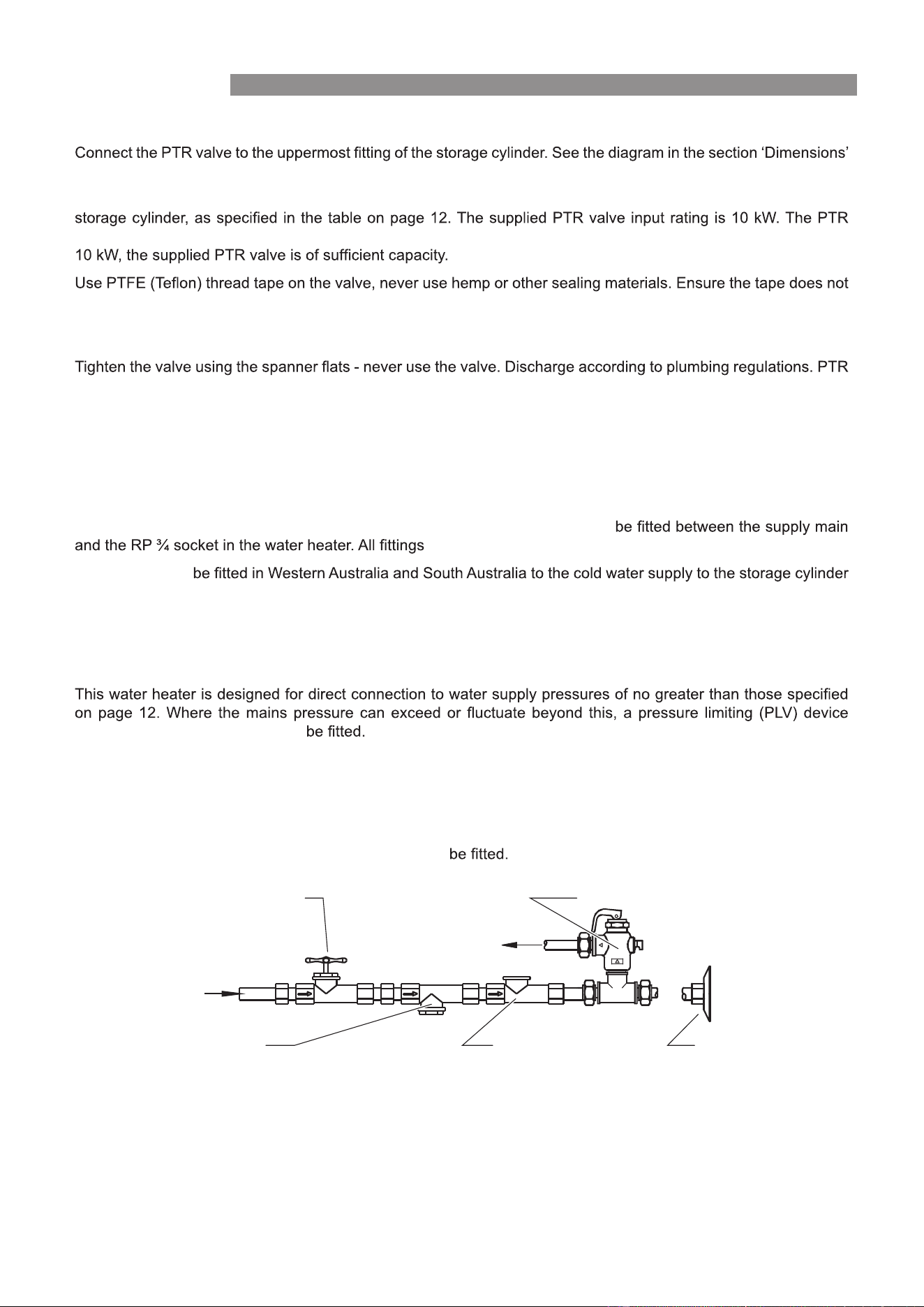
PLUMBING CONNECTIONS
Refer to the diagram on page 13 for detailed information on position of plumbing.
An approved isolating valve, non return valve, line strainer, and union MUST
MUST be approved by the relevant installation Authority.
An ECV MUST
to comply with local regulations.
An ECV is recommended in all other geographical areas where the water supply has a tendency to cause scaling.
This will reduce hot water discharge from the Pressure and Temperature Relief (PTR) valve which minimises wear
on this valve.
(complying with AS1357) MUST
CONNECT COLD / HOT WATER SUPPLY
Connect cold water supply, Pressure Limiting Valve (PLV) and or Expansion Control Valve (ECV).
Connect cold water supply to the storage tank (refer to Diagram BELOW).
A stop cock, non return valve and line strainer MUST
Connect the pipe work supplying hot water to the premises to the hot water outlet on the tank.
A temperature limiting device may be required as detailed in the section the section ‘Hot Water Delivery Temperature’
on page 17 .
It is recommended that all hot water lines are insulated with high temperature, UV resistant 13mm closed cell
insulation.
D ra in
Union Connection
Non-return ValveLine Strainer
Cold Water Inlet
Isolating Valve (Spindle Vertical)
Cold water expansion
control valve
INSTALLATION
Enviroflo Split Heat Pump OIM Issue 1 – MAY 2025Rinnai 21
DO NOT
(Megger) test has been performed.
Conducting Insulation (Megger) Tests
CONNECT CONDENSATE DRAIN LINE
The condensate drain line should not be connected to the PTR drain line but can exit
to the same point.
Independent 15mm copper pipes MUST
Each pipe MUST be open to atmosphere and run with a continual downward grade
in a frost free environment to a visible discharge point.
Drain lines MUST NOT exceed 9 meters in length. Valves or other restrictions
MUST NOT be placed in the relief valve drain outlet line.
ELECTRICAL TESTS
When conducting an insulation test using a Megger on this appliance, observe the following:
WARNING
This appliance contains electronic components, when performing insulation tests (500 Volts)
this MUST ONLY be conducted the across active terminal to earth and then across the neutral
terminal to earth.
Tests between the active to neutral terminals MUST NOT be performed as this WILL damage
the electronic components.
Insulation test results of between 100 kΩ and 660 kΩ are normal for this appliance.
In accordance with AS/NZS 3000 an insulation test with a result less than 1 MΩ is permitted where the appliance
is approved to a Standard applicable to that class of appliance.
complies with the insulation resistance requirements of AS/NZS 3000.
ELECTRICAL CONNECTIONS
WARNING
The power supply to the heat pump module MUST NOT
with water.
The premises wiring to the heater MUST be capable of withstanding the appliance load. Refer to
All electrical connections and wiring MUST be installed, maintained and removed by authorised
persons in accordance with AS/NZS 3000, and all other relevant local regulations and municipal
building codes including OH&S requirements.
IMPORTANT
In Australia, a Residual Current Circuit Breaker (RCD) must be installed to the power supply for
this appliance.
IMPORTANT
Disconnect all power prior to installation and commissioning.
This appliance is designed for single phase 240 Volts, AC mains electrical operation.
INSTALLATION
The diagram shows the condensate drain location on the heat pump. Use the
supplied drain hose to connect to the condensate outlet.
A condensation drain line is required to be fitted to carry discharge clear of the water heater.
The Heat Pump is NOT equipped with a power cord and plug and MUST be hard-wired to an
isolating switch with dedicated circuit as per the wiring rules. The supply terminals MUST be
connected to an independent AC 240V 50Hz power supply with a safety switch. The isolator
MUST effectively isolate all active supply conductors from the circuit. A method for
disconnection MUST be incorporated into the fixed wiring in accordance with the relevant
wiring rules and regulations.
Condensate Drain
Enviroflo Split Heat Pump OIM Issue 1 – MAY 2025
HEATNL N
Power Supply
230VAC, 50Hz
Supply to Tank
230VAC, 50Hz
1 4 2
Dry Contact(optional)
Off-peak PV COM
Rinnai 22
INSTALLATION
Heat Pump Electrical Connections
Tank Unit Electrical Connections
Element Heater Wires
Connection from Terminal Block
Reset
Neutral - N
Earth
Reset
Active - A
1
2
3
4
5
)
(
Tank Sensor
Terminal Block
Tank Unit
Electrical
Connection
Access
(Element Heater
Tank Sensor)
Enviroflo Split Heat Pump OIM Issue 1 – MAY 2025Rinnai 23
FILLING THE SYSTEM
Open hot water tap at sink.
.
If no leaks are detected water heating can commence.
COMMISSIONING AND FINISHING THE INSTALLATION
IMPORTANT
•
Piping and electrical wiring are all correct and Earthing wire is installed properly.
•
Pipe insulation is completed
•
•
Supply Voltage complies with rated voltage
•
Air intake and discharge are not obstructed
Turn on the heat pump unit and wait a few minutes for the system to start. Change operation mode or water
temperature setting if required (it is recommended to retain default setting).
After testing is completed demonstrate the functions and operation of heat pump water heater components to the
householder. Explain the need to drain the heat pump if freezing conditions are likely and when power may be shut
off for an extended time.
Also explain the importance of performing maintenance in accordance with this manual. Leave the manual with
the householder.
INSTALLATION
WIRING DIAGRAM
PE
Main EEV
BMS
Water Inlet Temp
Ambient Temp
Discharge Temp
Water Outlet Temp
Water Tank Temp
Suction Temp
LP Switch
Common
4-way valve
Crankcase Heater
Element
Relay
U
V
W
Electric Reactor
DC
Fan
Coil Pipe Temp
L
HEAT
3
Note:
1. The water tank temperature sensor probe must be inserted
into the tank dry well for proper temperature measurement.
2. If the electric element current exceeds 10A, the element
relay can only be used as a signal output.
17
17
AC-LAC-N
V
U
W
LOUT
LIN
N
N
18
18
HP Switch
N
3
19
KA1
20
Power Supply
230VAC, 50Hz
Water
Pump
21
19
20
EEV
2
1
Red
Brown
Off-peak
PV
1 4
4
COM
2
Yellow
User
Interface
Black
Black
Blue
OrangeOrange
Blue
Blue
Off-peak
PV Input
Brown
Pink
Yellow
Green
Red
Red
Yellow
Red
Black
Supply to Tank
230VAC, 50Hz
Dry Contact Input (optional)
Wiring Diagram
Model: SHPL70
Black
Blue
21
Enviroflo Split Heat Pump OIM Issue 1 – MAY 2025Rinnai 24
OPERATION
OPERATION OF CONTROLLER
CONTROLLER LAYOUT AND KEYS
Key Primary Functions
SET
Up/Add Down/SubFunction OKOn/Off
Fn
When the heat pump turns on, the control system initiates and will check the unit’s operating parameters. The
controller will check on all sensors and pressure switches. If conditions are suitable (i.e all reading within the
reasonable range) and there is enough energy available in the surrounding air, the fan and compressor will turn
on.
There will be 3 minutes delay from the time the heat pump is switched on before the fan and compressor begin
operating.
The unit is self-regulating so there are no internal adjustments to be made during commissioning. When the unit
is operated for the first time, it runs through an initial heat up cycle, allow time for the initial heat up cycle. Depend-
ing on the ambient conditions this can take several hours.
If for any reason the unit does not start, the water is cold and the controller unit is not displaying any LED lights,
an electrician should test that power is available to the heat pump.
All major functions are controlled by the Control Panel situated in the enclosure on the right of the unit.
Note: Carefully flip up the weatherproof cover. To close, gently press it until the locking tabs at the bottom lock in
place.
The following table describes the primary function of each key on the controller.
Key Icon Primary Functions
Indicates that you can page up, select parameters and increase
numerical values
It means that you can page down, select parameters and decrease
numerical values
ON/OFF switch key icon, only used to start and stop the unit.
Represents function key icon, which is only used for menu, cancel,
return and shift.
Represents confirm key icon, which is only used to enter, confirm,
reset and unlock.
Up/Add
Down/Sub
Function
On/Off
OK
Fn
Enviroflo Split Heat Pump OIM Issue 1 – MAY 2025
1. Turn ON/OFF the heat pump
When the unit is the first-time powered on, the display starts countdown interface. It enters main interface in 5
seconds automatically. Press ‘On/Off’ key to turn on the heat pump by following the prompt. Wait a few minutes
for the unit to start heating. If the screen was locked, press ‘OK’ key for 3 seconds to unlock first.
When turning off the unit, it will not function and the interface shows OFF on the top left corner.
The unit will enter the operation mode and setting it was in prior to shutdown (or factory default setting if it is the
first-time powered on).
2. Unlock the screen
If there is no key operation for 60 seconds, the screen will lock automatically. Press any key to light the screen,
and press ‘OK’ key for 3 seconds to unlock the screen.
Controller Operation Flow
CONTROLLER FUNCTIONS AND OPERATION
Press On/Off to turn ON/OFF unit
Press OK if faults occurred
Press Funcon
Press Funcon
for 3s
Set operation mode
State query
Clock query & setting
Wifi menu
Timing set
Manual defrost
Manual disinfection
History error
Press OK for 3s to unlock screen
Press Up/Down to change temperature setting
Query current faults
Power ON
Countdown Interface Main Interface
Rinnai 25
OPERATION

Enviroflo Split Heat Pump OIM Issue 1 – MAY 2025
3. Operation mode selection
Press ‘Function’ key to enter operation mode selection: ECO → STND → VACA → ELEC → HYBD. Press ‘Up’
or ‘Down’ to select and press ‘OK’ to confirm.
Note: the system default mode is ECO. When the unit is switched on for the first time, the system will operate
under ECO mode. Subsequently, the unit will start in the mode setting it was in prior to shutdown.
4. Water temperature setting
Press the ‘ Up ’ or ‘ Down ’ key to increase or decrease the water temperature setting value. The value changes
by 1°C. It is recommended not to alter the factory default temperature setting.
5. Clock query & setting
Press ‘Function’ key for 3 seconds then press ‘Up’ or ‘Down’ to select ‘Clock query’, and press ‘OK’ key to enter
the clock query & setting interface.
Press ‘Up’ or ‘Down’ to cycle the value and press ‘Function’ key to select year, month, day, hour, minute and
second setting, then press ‘OK’ key to save the setting.
6. Timer setting
Press ‘Function’ key for 3 seconds then press ‘Up’ or ‘Down’ to select ‘Timing set’, and press ‘OK’ key to enter
the timer setting interface.
The factory default timer is set to disabled. Once the timer is enabled, the ‘Start time’ and ‘Stop time’ will need
to be set.
STANDARD Mode:
The user should select this mode for use in the commercial application. In this mode, the water heating is
done by the compression system.
ECO Mode:
This is the default mode as the heat pumps leave the factory. In this mode, the water heating is done by the
compression system.
HYBRID Mode:
In this mode, when the water temperature is below 60°C, water heating is carried out by the compression
system. When the water is greater than 60°C, water heating is carried out by the resistive heating element.
ELECTRIC Mode:
In this mode, water heating is done by the resistive heating element.
VACATION Mode:
In this mode, water heating is done by the compression system. This mode is to be used when there is no
need for hot water for an extended period of water.
No.
1
2
3
4
5
Symbol
STND
HYBD
ELEC
VACA
Mode
Standard
Economy
Hybrid
Electric
Vacation
60
55
65
70
20
5
12
10
8
12
45~60
45~60
45~70
45~70
15~60
ECO
(Factory default)
Set Point - Factory
Default (℃)
Restart
Differential (℃)
Set Point
Range (℃)
Rinnai 26
OPERATION
Enviroflo Split Heat Pump OIM Issue 1 – MAY 2025
7. Operation state query
Press ‘Function’ key for 3 seconds then press ‘Up’ or ‘Down’ to select ‘State query’, and press ‘OK’ key to enter,
then select ‘System state query’ to enter the operation status interface.
8. Manual defrost
Press ‘Function’ key for 3 seconds then press ‘Up’ or ‘Down’ to select ‘Manual dfrst’, and press ‘OK’ key to
activate manual defrost operation. The unit performs manual defrost if certain conditions are satisfied.
9. Manual disinfection
Press ‘Function’ key for 3 seconds then press ‘Up’ or ‘Down’ to select ‘Manual disinf’, and press ‘OK’ key to
activate manual disinfection operation.
10. History error query
Press ‘Function’ key for 3 seconds then press ‘Up’ or ‘Down’ to select ‘History err’, and press ‘OK’ key to query
historical errors.
Rinnai 27
OPERATION
IMPORTANT
This type of connection MUST only be carried out by a qualified electrician.
IMPORTANT
The unit can not be connected to OFF PEAK meters.
In this case the system will be OFF (No power when connected to this meter) causing, the
disinfection timer to stop counting down.
If the water temperature drops below the required level for an extended period, there is a risk
of legionella developing in the hot water system.
1. Solar photovoltaic system
A solar photovoltaic signal can be integrated via the built-in dry contact input ‘PV’ on the terminal block. When the
heat pump receives ‘closed’ signal from the solar PV system and the signal lasts for 30 seconds, the restart differen-
tial will temporarily change to 2°C for at least 10 minutes to take advantage of electricity generated on site to produce
more hot water.
2. Off-peak electricity
Off-peak tariff signal can be integrated via the built-in dry contact input ‘OP’ on the terminal block. The terminals are
pre-wired to bridge. Remove the bridge and connect off-peak signal if required. The unit will be only operating at
receiving ‘closed’ signal. This feature accesses the heat pump to utilize off-peak electricity.
CONNECTION OF EXTERNAL SIGNALS (OPTIONAL)

Enviroflo Split Heat Pump OIM Issue 1 – MAY 2025
Please follow below steps to set up and operate Wi-Fi functions.
1. Prepare a Wi-Fi wireless router that can access the Internet, The Wi-Fi frequency band must be 2.4 GHz and
should be placed within 10 meters of the water heater to ensure that a strong Wi-Fi signal is available.
2. Turn on Wi-Fi and Bluetooth on your device. After the connection is successful, you can turn off Bluetooth and
operation will not be affected.
3. Scan the QR code below or search in the app market to download and install the ‘Smart Life’ App.
* iOS users – please download from App Store
* Android users – please download from Google Play
4. After completing the installation, open the App, register an account and log in according to the App prompt.
Wi-Fi Connection
Rinnai 28
WI
-
FI

Enviroflo Split Heat Pump OIM Issue 1 – MAY 2025Rinnai 29
I) Search for Device II) Add Found Device III) Connect to Wi-Fi
IV) Wait to Connect V) Complete
5. Connect to the SmartLife App as follows:
WI
-
FI
30
WI
-
FI
Enviroflo Split Heat Pump OIM Issue 1 – MAY 2025Rinnai
7. Set timer from the App
6. Control the Heat Pump with the App
The main controls for the App are laid out as follows on the App.
Adjust Temp
Se�ng
Turn
On/0ff
Select
Mode
Status
Check
HisErr
Check
Se�ng
Timer

31
WI-FI TROUBLESHOOTING
Issue
Configuration
cannot
be completed
Potential Cause
Check that you are only connected to the 2.4 GHz WIFI frequency. You may be
required to temporarily turn off you 5.0 GHz WIFI frequency at the modem during
the configuration process.
Check your WIFI signal strength at the hot water unit. You will require a minimum
of 3 bars WIFI signal to be connected.
Check you have the correct app downloaded.
Check you have the minimum requirements as stated at the beginning of
this manual.
WI
-
FI

Enviroflo Split Heat Pump OIM Issue 1 – MAY 2025R1.07.01.00043
Rinnai Australia Pty Ltd
ABN 74 005 138 769 | AU45204
100 Atlantic Drive, Keysborough, Victoria 3173
P.O. Box 460, Braeside, Victoria 3195
Tel: (03) 9271 6625
National Help Line
Tel: 1300 555 545*
Monday to Friday, 8.00 am to 5.00 pm EST.
After Hours Hot Water Service Line
Tel: 1800 000 340*
*Cost of a local call may be higher from a mobile phone.
(National calls from public phones in Australia are free.)
For further information visit www.rinnai.com.au
Rinnai has a Service and Spare Parts network with
personnel who are fully trained and equipped to give
the best service on your Rinnai appliance. If your
appliance requires service, please call our National
Help Line. Rinnai recommends that this appliance be
serviced every 3 years.
With our policy of continuous improvement, we
reserve the right to change, or discontinue at any time,
specifications or designs without notice.