Form No. 3469-915 Rev A
TX 700 Compact T ool Carrier
Model No. 22351 —Serial No. 412900000 and Up
Model No. 22351G —Serial No. 400000000 and Up
Model No. 22352 —Serial No. 412900000 and Up
Register at www .T oro.com.
Original Instructions (EN)
*3469-915*
This product complies with all relevant European
directives; for details, please see the separate product
specic Declaration of Conformity (DOC) sheet.
It is a violation of California Public Resource Code
Section 4442 or 4443 to use or operate the engine on
any forest-covered, brush-covered, or grass-covered
land unless the engine is equipped with a spark
arrester , as dened in Section 4442, maintained in
ef fective working order or the engine is constructed,
equipped, and maintained for the prevention of re.
The enclosed engine owner's manual is supplied
for information regarding the US Environmental
Protection Agency (EP A) and the California Emission
Control Regulation of emission systems, maintenance,
and warranty . Replacements may be ordered through
the engine manufacturer .
W ARNING
CALIFORNIA
Proposition 65 W arning
Diesel engine exhaust and some of its
constituents are known to the State of
California to cause cancer , birth defects,
and other reproductive harm.
Battery posts, terminals, and related
accessories contain lead and lead
compounds, chemicals known to
the State of California to cause
cancer and reproductive harm. W ash
hands after handling.
Use of this product may cause exposure
to chemicals known to the State of
California to cause cancer , birth defects,
or other reproductive harm.
Introduction
This machine is a compact tool carrier intended for
use in various earth and materials moving activities for
landscaping and construction work. It is designed to
operate a wide variety of attachments, each of which
perform a specialized function. Using this product
for purposes other than its intended use could prove
dangerous to you and bystanders. Do not modify the
machine or attachments.
This machine should be operated, serviced, and
repaired only by professionals familiar with its
characteristics and acquainted with the relevant safety
procedures.
Operate this machine in ambient temperatures from
-18 to 38°C (0 to 100 °F). Contact your Authorized
Service Dealer for provisions required for operating
in extreme temperatures.
Read this information carefully to learn how to operate
and maintain your product properly and to avoid
injury and product damage. Y ou are responsible for
operating the product properly and safely .
V isit www .T oro.com for product safety and operation
training materials, accessory information, help nding
a dealer , or to register your product.
Whenever you need service, genuine T oro parts, or
additional information, contact an Authorized Service
Dealer or T oro Customer Service and have the model
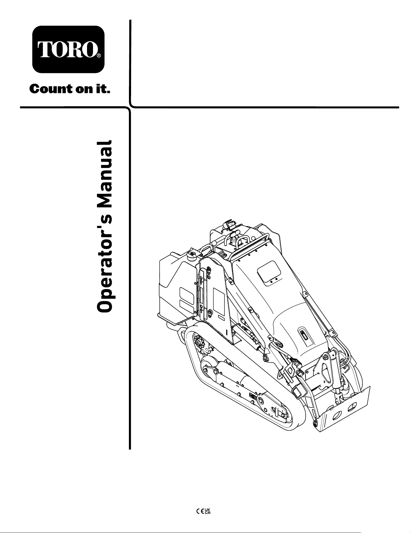
and serial numbers of your product ready . Figure 1
identies the location of the model and serial numbers
on the product. W rite the numbers in the space
provided.
Important: W ith your mobile device, you can
scan the QR code on the serial number decal (if
equipped) to access warranty , parts, and other
product information.
g367614
Figure 1
1. Model and serial number location
Model No.
Serial No.
This manual identies potential hazards and has
safety messages identied by the safety-alert symbol
( Figure 2 ), which signals a hazard that may cause
serious injury or death if you do not follow the
recommended precautions.
© 2024—The T oro® Company
81 1 1 L yndale A venue South
Bloomington, MN 55420
2
Contact us at www .T oro.com.
Printed in the USA
All Rights Reserved

g000502
Figure 2
Safety-alert symbol
This manual uses 2 words to highlight information.
Important calls attention to special mechanical
information and Note emphasizes general information
worthy of special attention.
Contents
Safety . . . . . . . . . . . . . . . . . . . . . . . . . . . . . . . . . . . . . . . . . . . . . . . . . . . . . . . . . . . . . . . . . . . . . . . 4
General Safety . . . . . . . . . . . . . . . . . . . . . . . . . . . . . . . . . . . . . . . . . . . . . . . . . . . 4
Safety and Instructional Decals . . . . . . . . . . . . . . . . . . . . . . . . . . 5
Product Overview . . . . . . . . . . . . . . . . . . . . . . . . . . . . . . . . . . . . . . . . . . . . . . . . . . . . 1 1
Controls . . . . . . . . . . . . . . . . . . . . . . . . . . . . . . . . . . . . . . . . . . . . . . . . . . . . . . . . . . . 12
Message Display . . . . . . . . . . . . . . . . . . . . . . . . . . . . . . . . . . . . . . . . . . . 15
Specications . . . . . . . . . . . . . . . . . . . . . . . . . . . . . . . . . . . . . . . . . . . . . . . . . . 16
Attachments/Accessories . . . . . . . . . . . . . . . . . . . . . . . . . . . . . . . . . 16
Before Operation . . . . . . . . . . . . . . . . . . . . . . . . . . . . . . . . . . . . . . . . . . . . . . . . . 16
Before Operation Safety . . . . . . . . . . . . . . . . . . . . . . . . . . . . . . . . . . . 16
Adding Fuel . . . . . . . . . . . . . . . . . . . . . . . . . . . . . . . . . . . . . . . . . . . . . . . . . . . . . . 17
Performing Daily Maintenance . . . . . . . . . . . . . . . . . . . . . . . . . . 18
During Operation . . . . . . . . . . . . . . . . . . . . . . . . . . . . . . . . . . . . . . . . . . . . . . . . . 18
During Operation Safety . . . . . . . . . . . . . . . . . . . . . . . . . . . . . . . . . . . 18
Starting the Engine . . . . . . . . . . . . . . . . . . . . . . . . . . . . . . . . . . . . . . . . . . . 20
Driving the Machine . . . . . . . . . . . . . . . . . . . . . . . . . . . . . . . . . . . . . . . . . . 20
Shutting Of f the Engine . . . . . . . . . . . . . . . . . . . . . . . . . . . . . . . . . . . . . 20
Using Attachments . . . . . . . . . . . . . . . . . . . . . . . . . . . . . . . . . . . . . . . . . . . 20
After Operation . . . . . . . . . . . . . . . . . . . . . . . . . . . . . . . . . . . . . . . . . . . . . . . . . . . . 22
After Operation Safety . . . . . . . . . . . . . . . . . . . . . . . . . . . . . . . . . . . . . . 22
Retrieving a Stuck Machine . . . . . . . . . . . . . . . . . . . . . . . . . . . . . . 23
Moving a Non-Functioning Machine . . . . . . . . . . . . . . . . . . 23
Hauling the Machine . . . . . . . . . . . . . . . . . . . . . . . . . . . . . . . . . . . . . . . . . 24
Lifting the Machine . . . . . . . . . . . . . . . . . . . . . . . . . . . . . . . . . . . . . . . . . . . 26
Maintenance . . . . . . . . . . . . . . . . . . . . . . . . . . . . . . . . . . . . . . . . . . . . . . . . . . . . . . . . . . . 27
Maintenance Safety . . . . . . . . . . . . . . . . . . . . . . . . . . . . . . . . . . . . . . . . . . 27
Recommended Maintenance Schedule(s) . . . . . . . . . . . 27
Pre-Maintenance Procedures . . . . . . . . . . . . . . . . . . . . . . . . . . . . . . 29
Using the Cylinder Locks . . . . . . . . . . . . . . . . . . . . . . . . . . . . . . . . . . 29
Accessing Internal Components . . . . . . . . . . . . . . . . . . . . . . . 29
Lubrication . . . . . . . . . . . . . . . . . . . . . . . . . . . . . . . . . . . . . . . . . . . . . . . . . . . . . . . . . . 32
Greasing the Machine . . . . . . . . . . . . . . . . . . . . . . . . . . . . . . . . . . . . . . . 32
Engine Maintenance . . . . . . . . . . . . . . . . . . . . . . . . . . . . . . . . . . . . . . . . . . . 32
Engine Safety . . . . . . . . . . . . . . . . . . . . . . . . . . . . . . . . . . . . . . . . . . . . . . . . . . . 32
Servicing the Air-Cleaner . . . . . . . . . . . . . . . . . . . . . . . . . . . . . . . . . . 32
Servicing the Engine Oil . . . . . . . . . . . . . . . . . . . . . . . . . . . . . . . . . . . . 34
Fuel System Maintenance . . . . . . . . . . . . . . . . . . . . . . . . . . . . . . . . . . . 36
Draining the W ater Separator . . . . . . . . . . . . . . . . . . . . . . . . . . . 36
Replacing the W ater Separator Filter . . . . . . . . . . . . . . . . 37
Replacing the In-Line Fuel Filter . . . . . . . . . . . . . . . . . . . . . . . 37
Checking the Fuel Lines and
Connections . . . . . . . . . . . . . . . . . . . . . . . . . . . . . . . . . . . . . . . . . . . . . . . . . . 37
Bleeding the Fuel System . . . . . . . . . . . . . . . . . . . . . . . . . . . . . . . . . 38
Draining the Fuel T ank(s) . . . . . . . . . . . . . . . . . . . . . . . . . . . . . . . . . . 38
Electrical System Maintenance . . . . . . . . . . . . . . . . . . . . . . . . . . . 38
Electrical System Safety . . . . . . . . . . . . . . . . . . . . . . . . . . . . . . . . . . . 38
Using the Battery-Disconnect Switch . . . . . . . . . . . . . . . . 38
Servicing the Battery . . . . . . . . . . . . . . . . . . . . . . . . . . . . . . . . . . . . . . . . . 39
Jump-Starting the Machine . . . . . . . . . . . . . . . . . . . . . . . . . . . . . . . 41
Servicing the Fuses . . . . . . . . . . . . . . . . . . . . . . . . . . . . . . . . . . . . . . . . . . 42
Drive System Maintenance . . . . . . . . . . . . . . . . . . . . . . . . . . . . . . . . . . 43
Servicing the T racks . . . . . . . . . . . . . . . . . . . . . . . . . . . . . . . . . . . . . . . . . 43
Cooling System Maintenance . . . . . . . . . . . . . . . . . . . . . . . . . . . . . . 46
Cooling System Safety . . . . . . . . . . . . . . . . . . . . . . . . . . . . . . . . . . . . . 46
Servicing the Cooling System . . . . . . . . . . . . . . . . . . . . . . . . . . . 46
Brake Maintenance . . . . . . . . . . . . . . . . . . . . . . . . . . . . . . . . . . . . . . . . . . . . . 48
T esting the Parking Brake . . . . . . . . . . . . . . . . . . . . . . . . . . . . . . . . . 48
Belt Maintenance . . . . . . . . . . . . . . . . . . . . . . . . . . . . . . . . . . . . . . . . . . . . . . . . 48
Checking the Alternator-Belt T ension . . . . . . . . . . . . . . . . 48
Controls System Maintenance . . . . . . . . . . . . . . . . . . . . . . . . . . . . . 49
Adjusting the Controls . . . . . . . . . . . . . . . . . . . . . . . . . . . . . . . . . . . . . . . 49
Hydraulic System Maintenance . . . . . . . . . . . . . . . . . . . . . . . . . . . 49
Hydraulic System Safety . . . . . . . . . . . . . . . . . . . . . . . . . . . . . . . . . . . 49
Relieving Hydraulic Pressure . . . . . . . . . . . . . . . . . . . . . . . . . . . . 49
Hydraulic Fluid Specications . . . . . . . . . . . . . . . . . . . . . . . . . . . 50
Checking the Hydraulic-Fluid Level . . . . . . . . . . . . . . . . . . . 50
Replacing the Hydraulic Filter . . . . . . . . . . . . . . . . . . . . . . . . . . . 51
Changing the Hydraulic Fluid . . . . . . . . . . . . . . . . . . . . . . . . . . . . 51
Cleaning . . . . . . . . . . . . . . . . . . . . . . . . . . . . . . . . . . . . . . . . . . . . . . . . . . . . . . . . . . . . . . 52
Removing Debris . . . . . . . . . . . . . . . . . . . . . . . . . . . . . . . . . . . . . . . . . . . . . . 52
W ashing the Machine . . . . . . . . . . . . . . . . . . . . . . . . . . . . . . . . . . . . . . . 52
Cleaning the Chassis . . . . . . . . . . . . . . . . . . . . . . . . . . . . . . . . . . . . . . . . 52
Storage . . . . . . . . . . . . . . . . . . . . . . . . . . . . . . . . . . . . . . . . . . . . . . . . . . . . . . . . . . . . . . . . . . . 53
Storage Safety . . . . . . . . . . . . . . . . . . . . . . . . . . . . . . . . . . . . . . . . . . . . . . . . . . 53
Storage . . . . . . . . . . . . . . . . . . . . . . . . . . . . . . . . . . . . . . . . . . . . . . . . . . . . . . . . . . . . . 53
T roubleshooting . . . . . . . . . . . . . . . . . . . . . . . . . . . . . . . . . . . . . . . . . . . . . . . . . . . . . . 54
3

Safety
General Safety
DANGER
There may be buried utility lines in the work
area. Digging into them may cause a shock
or an explosion.
Have the property or work area marked for
buried lines and do not dig in marked areas.
Contact your local marking service or utility
company to have the property marked (for
example, in the US, call 81 1 or in Australia,
call 1 100 for the nationwide marking service).
Always follow all safety instructions to avoid serious
injury or death.
• Do not exceed the rated operating capacity , as the
machine may become unstable, which may result
in loss of control.
• Do not carry a load with the arms raised; always
carry loads close to the ground.
• Slopes are a major factor related to loss-of-control
and tip-over accidents, which can result in severe
injury or death. Operating the machine on any
slope or uneven terrain requires extra caution.
• Operate the machine up and down slopes with
the heavy end of the machine uphill and the
load close to the ground. W eight distribution
changes with attachments. An empty bucket
makes the rear of the machine the heavy end, and
a full bucket makes the front of the machine the
heavy end. Most other attachments make the front
of the machine the heavy end.
• Have the property or work area marked for buried
lines and other objects, and do not dig in marked
areas.
• Read and understand the content of this Operator ’ s
Manual before starting the engine.
• Use your full attention while operating the
machine. Do not engage in any activity that
causes distractions; otherwise, injury or property
damage may occur .
• Never allow children or untrained people to
operate the machine.
• Keep your hands and feet away from the moving
components and attachments.
• Do not operate the machine without the guards
and other safety protective devices in place and
working on the machine.
• Keep bystanders and children out of the operating
area.
• Stop the machine, shut of f the engine, and remove
the key before servicing, fueling, or unclogging
the machine.
Improperly using or maintaining this machine
can result in injury . T o reduce the potential for
injury , comply with these safety instructions and
always pay attention to the safety-alert symbol
,
which means Caution, W arning, or Danger—personal
safety instruction. Failure to comply with these
instructions may result in personal injury or death.
4
Safety and Instructional Decals
Safety decals and instructions are easily visible to the operator and are located near any area
of potential danger . Replace any decal that is damaged or missing.
decalbatterysymbols
Battery Symbols
Some or all of these symbols are on your battery .
1. Explosion hazard 6. Keep bystanders away
from the battery .
2. No re, open ame, or
smoking
7. W ear eye protection;
explosive gases can
cause blindness and other
injuries.
3. Caustic liquid/chemical
burn hazard
8. Battery acid can cause
blindness or severe burns.
4. W ear eye protection. 9. Flush eyes immediately
with water and get medical
help fast.
5. Read the Operator's
Manual .
10. Contains lead; do not
discard
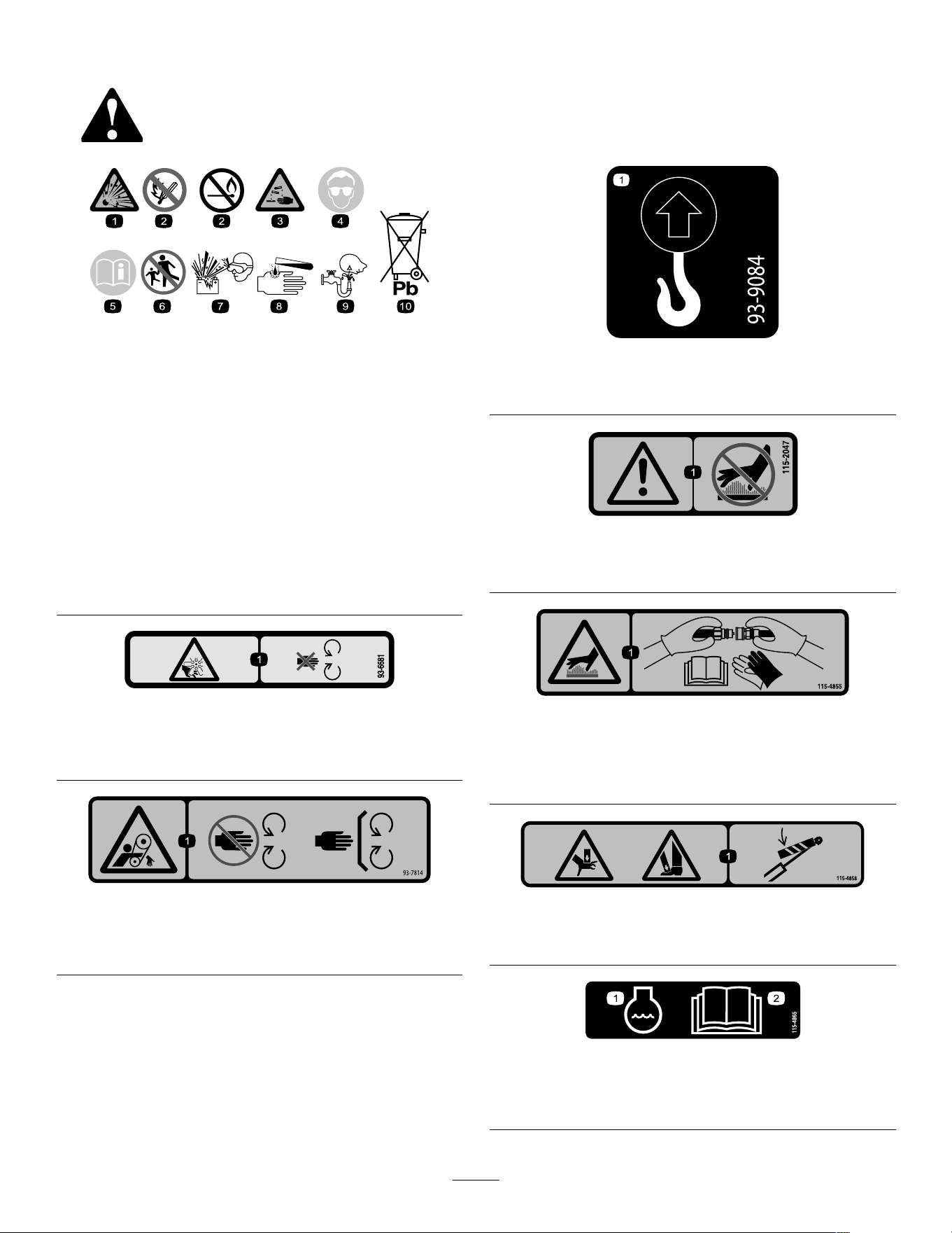
decal93-6681
93-6681
1. Cutting/dismemberment hazard, fan—stay away from
moving parts.
decal93-7814
93-7814
1. Entanglement hazard, belt—stay away from moving parts;
keep all guards and shields in place.
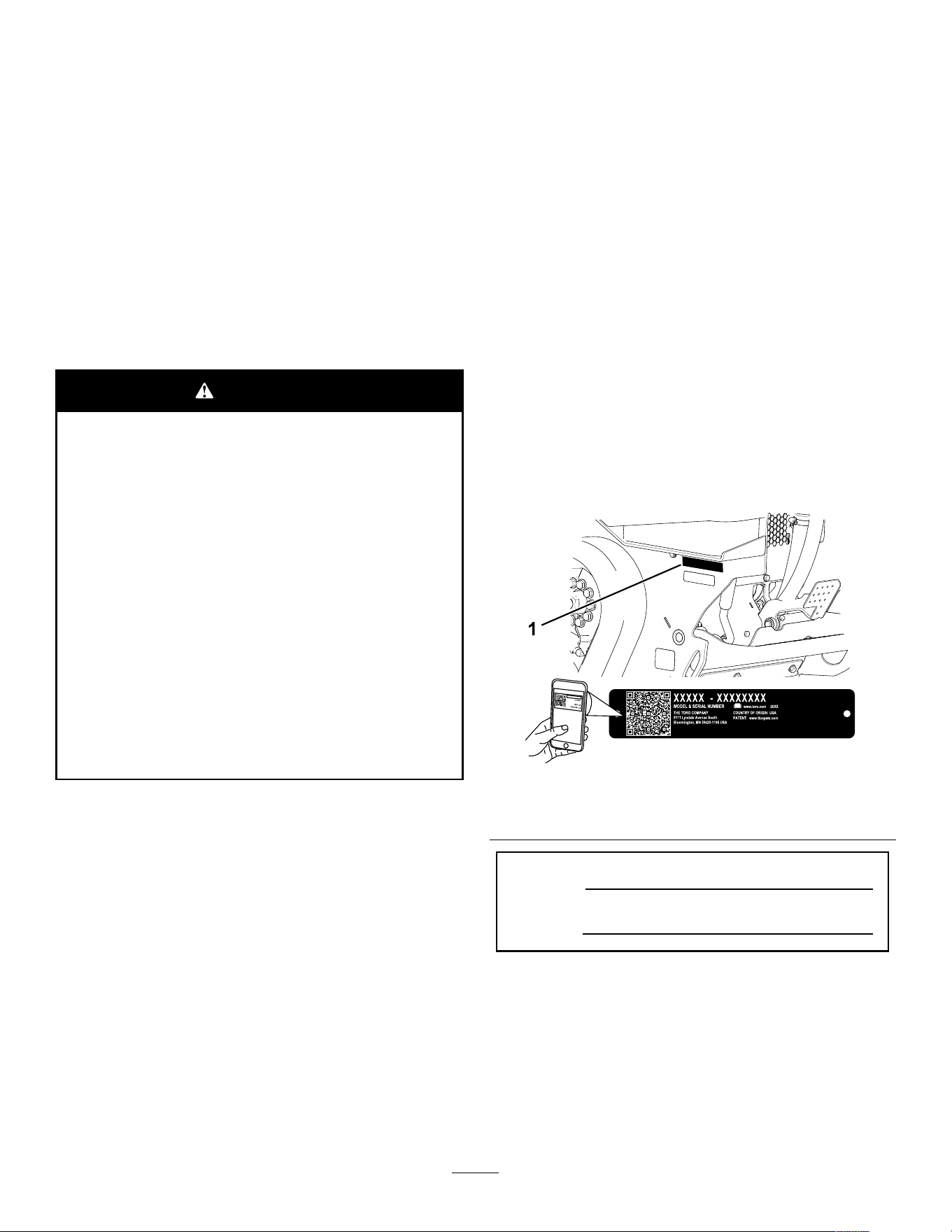
decal93-9084
93-9084
1. Lift point
decal1 15-2047
1 15-2047
1. W arning—do not touch the hot surface.
decal1 15-4855
1 15-4855
1. Hot surface/burn hazard—wear protective gloves when
handling the hydraulic couplers and read the Operator's
Manual for information on handling hydraulic components.
decal1 15-4858
1 15-4858
1. Crushing hazard of hands or feet—install the cylinder lock.
decal1 15-4865
1 15-4865
1. Engine coolant
2. Read the Operator's
Manual .
5
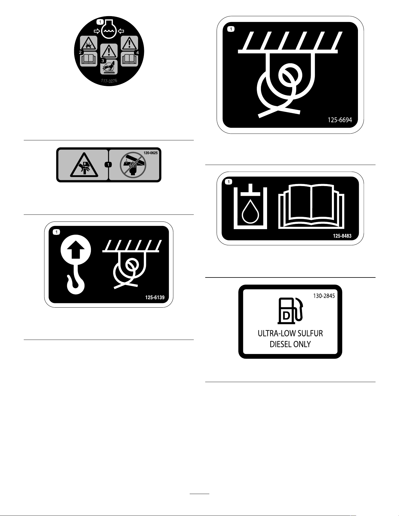
decal1 17-3276
1 17-3276
1. Engine coolant under
pressure
3. W arning—do not touch the
hot surface.
2. Explosion hazard—read
the Operator's Manual .
4. W arning—read the
Operator's Manual .
decal120-0625
120-0625
1. Pinch point, hand—keep hands away .
decal125-6139
125-6139
1. Lift point and tie-down point
decal125-6694
125–6694
1. T ie down location
decal125-8483
125-8483
1. Hydraulic uid; read the Operator ’ s Manual .
decal130-2845
130–2845
6
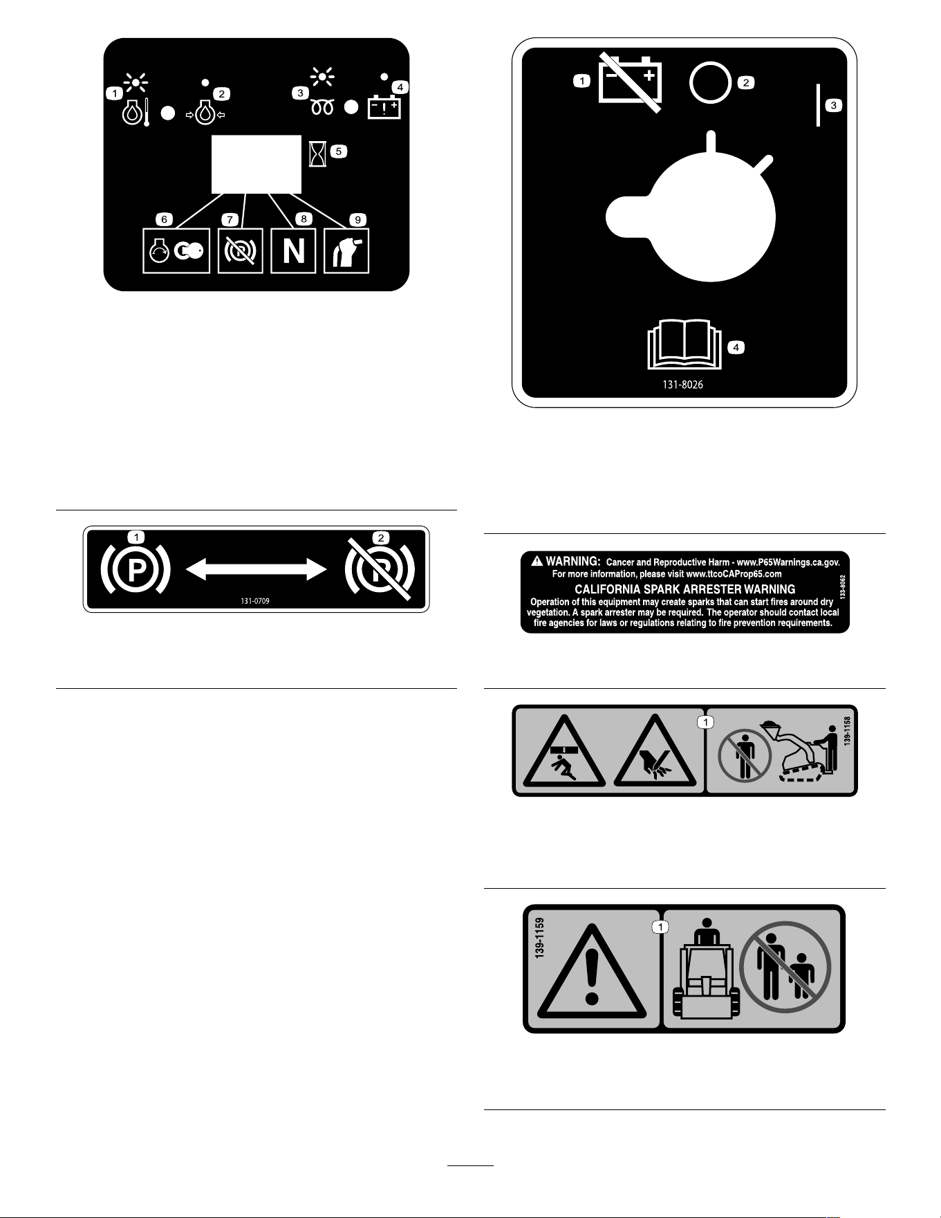
decal130-7637
130-7637
1. Blinking
light—engine-coolant
temperature
6. Engine start
2. Steady light—engine-oil
pressure
7. Parking brake disengaged
3. Blinking light—glow plug 8. T raction neutral
4. Steady light—battery
warning
9. Auxiliary lever neutral
5. Hourmeter
decal131-0709
131-0709
1. Parking brake—engage 2. Parking brake—disengage
decal131-8026
131-8026
1. Battery
power—disconnect
3. On
2. Of f 4. Read the Operator's
Manual .
decal133-8062
133-8062
decal139-1 158
139-1 158
1. Crushing hazard, from above, and pinching hazard—stay
away from the bucket and loading arms.
decal139-1 159
139-1 159
1. W arning—keep bystanders away .
7
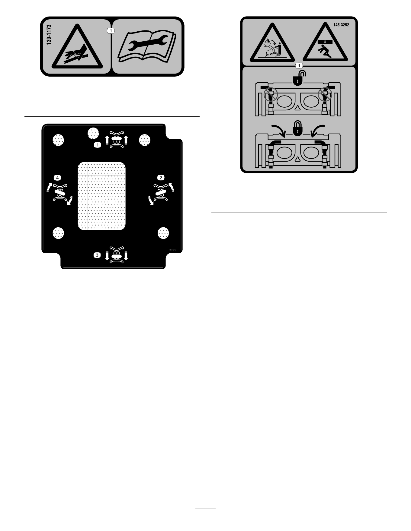
decal139-1 173
139-1 173
1. High-pressure uid hazard, injection into the body—read
the Operator ’ s Manual before performing maintenance.
decal145-3242
145-3242
1. Move forward
3. Move rearward
2. T urn left
4. T urn right
decal145-3252
145-3252
1. Crushing hazard from above, falling load—ensure that the
quick-attach pins are locked.
8
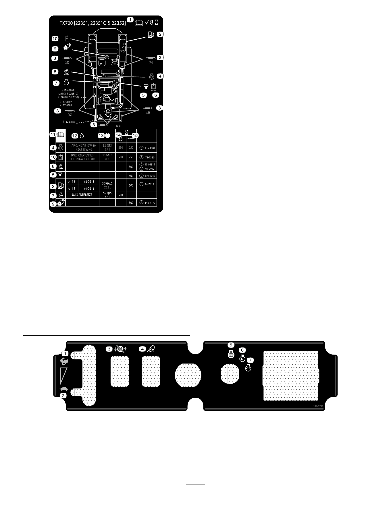
decal147-9016
147-9016
1. Read the Operator ’ s
Manual ; Check every 8
hours
9. Belt tension
2. Diesel fuel 10. Hydraulic uid
3. Grease points 1 1. Read the Operator ’ s
Manual .
4. Engine oil
12. Fluid specication
5. Fuel/water separator 13. Capacity
6. Hydraulic uid lter
14. Fluid change interval
(hours)
7. Engine coolant 15. Filter change interval
(hours)
8. Engine air lter
decal140-5791
140-5791
1. Fast 5. Engine—start
2. Slow
6. Engine—run
3. T raction disabled
7. Engine—shut of f
4. W ork light
9
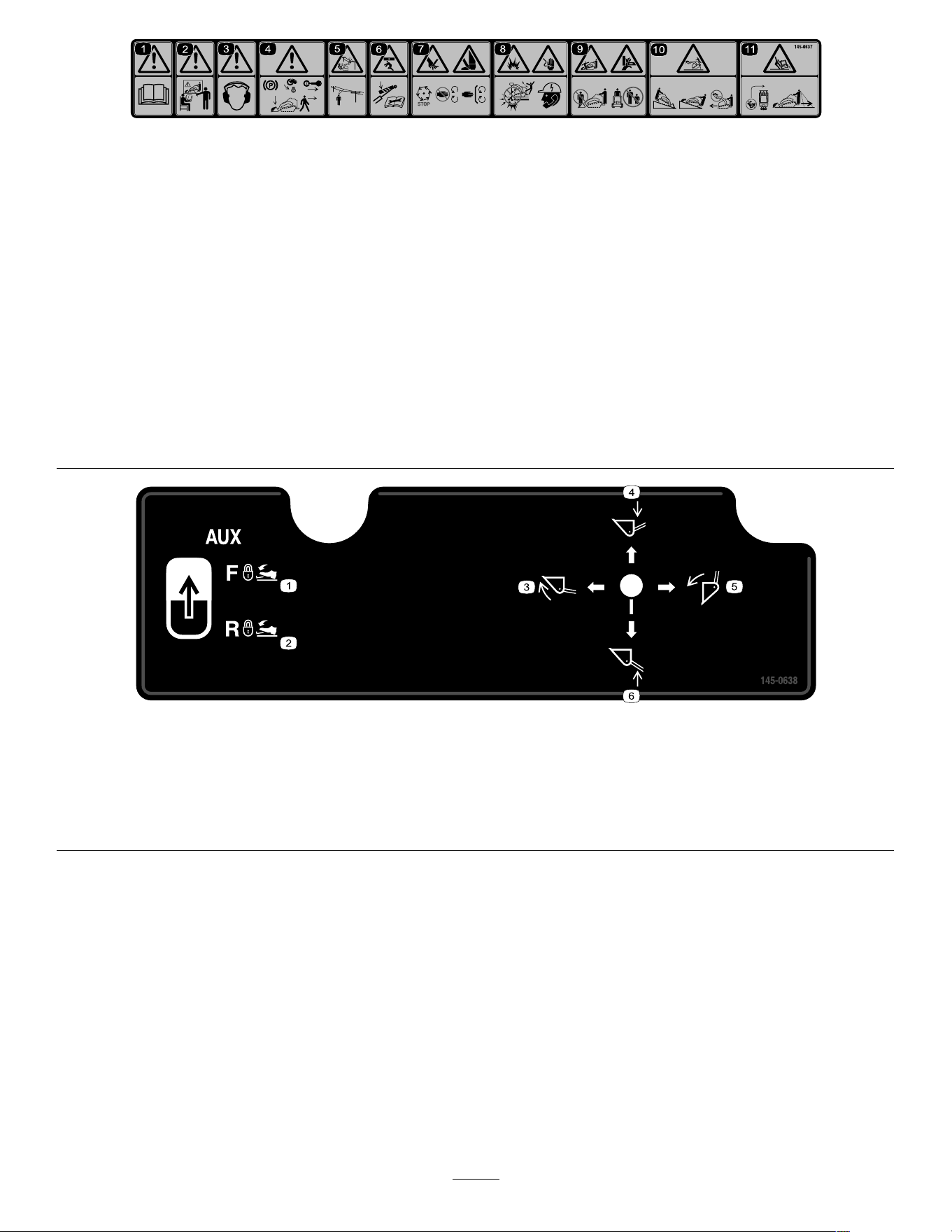
decal145-0637
145-0637
1. W arning—read the Operator's Manual . 7. Cutting/severing hazard of hand or foot—wait for all moving
parts to stop before servicing; keep away from moving parts;
keep all guards and shields in place.
2. W arning—receive training before operating the machine.
8. Explosion hazard; electrocution hazard—call the local utilities
hotline before beginning work in an area.
3. W arning—wear hearing protection.
9. Crushing hazard—keep away from the attachment when
operating the machine; keep bystanders away from the
machine.
4. W arning—engage the parking brake, lower the attachment to
the ground, shut of f the engine, and remove the key from the
ignition before leaving the machine.
10. T ipping hazard—always move up or down slopes with
the attachment lowered; never drive on a slope with the
attachment raised; always operate with the heavy end uphill;
always carry loads low; never jerk the control levers; use
a steady , even motion.
5. Electrocution hazard, power lines—check for power lines in
the area before using the machine.
1 1. T ipping hazard—do not make fast turns; always check behind
you before reversing the machine.
6. Crushing hazard—install the cylinder lock; read the Operator's
Manual before servicing or performing maintenance.
decal145-0638
145-0638
1. Hydraulic attachment—forward; lock the hydraulic ow using
the foot pedal.
4. Lower the attachment.
2. Hydraulic attachment-—reverse; lock the hydraulic ow using
the foot pedal.
5. T ilt the attachment rearward.
3. T ilt the attachment forward.
6. Raise the attachment.
10
Product Overview
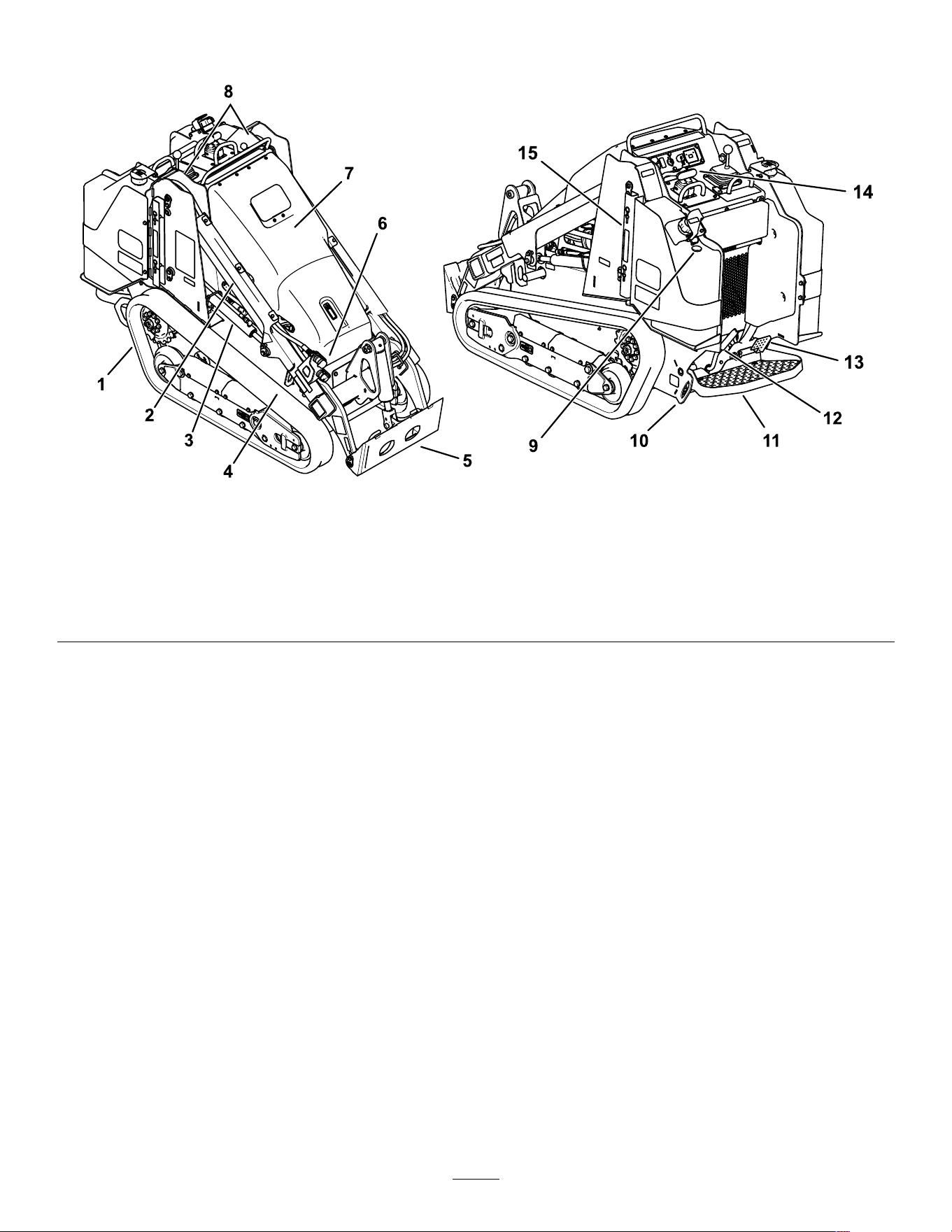
g41 1227
Figure 3
1. T rack 6. Auxiliary hydraulic couplers
1 1. Operator platform
2. Loader arm 7. Hood 12. Parking brake
3. Lift cylinder 8. Lift point
13. Auxiliary hydraulics lock pedal
4. T ie-down/lift loop
9. Fuel gauge
14. Control panel
5. Mount plate 10. T ie-down loop
15. Cylinder lock
1 1
Controls
Become familiar with all the controls before you start
the engine and operate the traction unit.
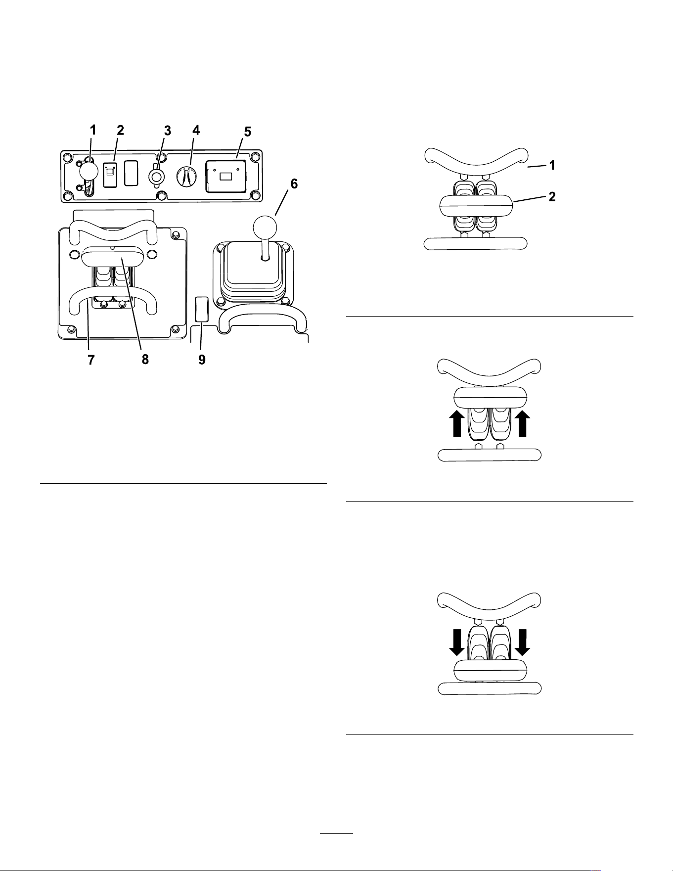
Control Panel
g41 1223
Figure 4
1. Throttle lever
6. Loader-arm/attachment-tilt
lever
2. T raction-enable switch
7. Reference bar
3. Power socket 8. T raction control
4. Key switch 9. Auxiliary hydraulics switch
5. Hour meter 10. Loader valve lock
Key Switch
The key switch, used to start and shut of f the engine,
has 3 positions: O FF , R UN , and S TART .
Throttle Lever
Move the control forward to increase the engine speed
and rearward to decrease speed.
Reference Bar
When driving the traction unit, use the reference bar
as a handle and a leverage point for controlling the
traction control and the auxiliary-hydraulics lever . T o
ensure smooth, controlled operation, do not take
your hands of f the reference bars while operating the
machine.
T raction-Enable Switch
The traction control is automatically disabled when
starting the machine. T oggle the traction-enable
switch after starting the machine to use the traction
control.
T raction Control
g259646
Figure 5
1. Reference bar
2. T raction control
• T o move forward, move the traction control
forward.
g259645
Figure 6
• T o move rearward, move the traction control
rearward.
Important: When reversing, look behind you
for obstructions and keep your hands on the
reference bar .
g259647
Figure 7
12
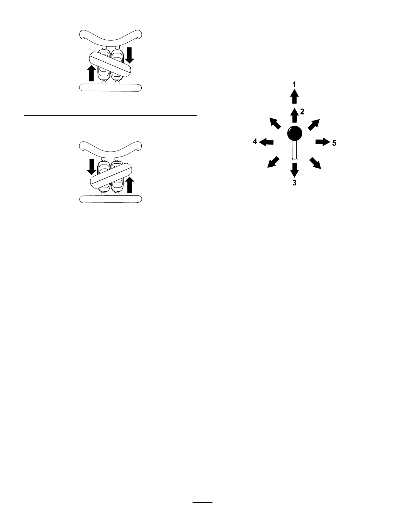
• T o turn right, rotate the traction control clockwise.
g259649
Figure 8
• T o turn left, rotate the traction control
counterclockwise.
g259648
Figure 9
• T o stop the machine, release the traction control.
Note: The farther you move the traction control in
any direction, the faster the machine moves in that
direction.
Loader Arm/Attachment-T ilt Lever
Slowly move the lever to operate the loader arms and
tilt the attachment.
Note: The detent (oat) position allows attachments
such as the leveler and the hydraulic blade to follow
the contours of the ground (i.e., oat) when grading.
g356466
Figure 10
1. Detent (oat)
position—push the lever
fully forward.
4. T ilt the attachment
rearward.
2. Lower the loader arms. 5. T ilt the attachment
forward.
3. Raise the loader arms.
By moving the lever to an intermediate position (e.g.,
forward and left), you can move the loader arms and
tilt the attachment at the same time.
Loader-Control-Reference Bar
The loader-control-reference bar helps stabilize your
hand while operating the loader arm/attachment-tilt
lever ( Figure 4 ).
13
Auxiliary-Hydraulics Controls
g41 1222
Figure 1 1
1. Operate auxiliary
hydraulics in the forward
direction.
2. Operate auxiliary
hydraulics in the reverse
direction.
Auxiliary-Hydraulics Lock Pedal
Use your right foot to press the auxiliary-hydraulics
lock pedal to continue the forward or reverse ow of
the auxiliary hydraulics and free your hand for other
controls.
g357086
Figure 12
1. Auxiliary-hydraulics lock pedal
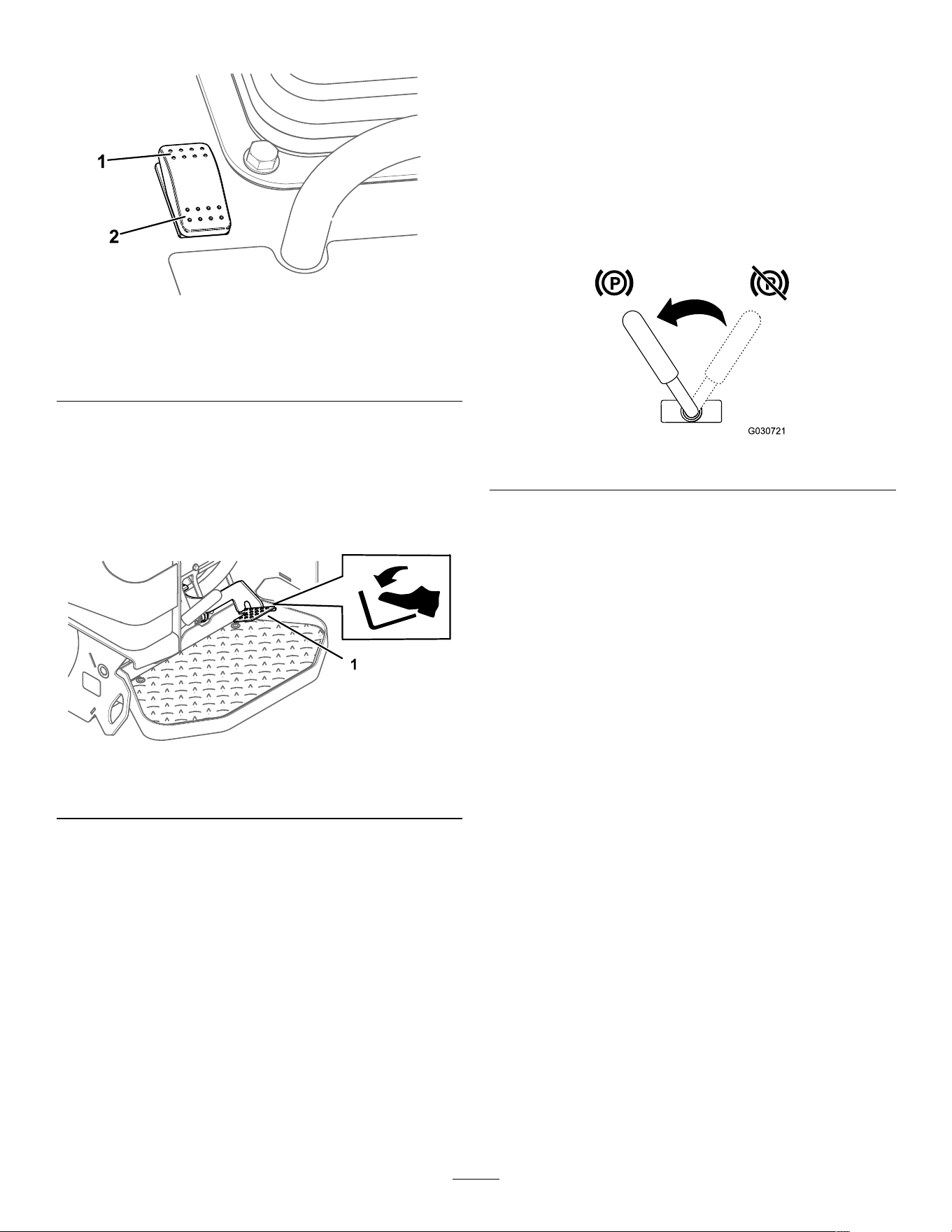
Parking-Brake Lever
• T o engage the parking brake, rotate the lever to
left.
Note: The traction unit may roll slightly before the
brakes engage in the drive sprocket.
• T o release the brake, rotate the brake lever to the
right.
Note: Y ou may need to adjust the traction control
to release the brake pins and rotate the lever .
g030721
Figure 13
Fuel Gauge
This gauge measures the amount of fuel in the fuel
tank(s).
14

Message Display
Engine-Coolant-T emperature Light
If the engine coolant becomes too hot, the light on
the left of the display ashes and the horn sounds. If
this happens, disengage the auxiliary hydraulics and
let the machine run at high idle to allow the cooling
system to cool the machine. Check the coolant level
when the engine has fully cooled.
Important: Do not shut off the engine, as this
may cause the machine to overheat.
g029201
Figure 14
Engine-Oil-Pressure Light
If the engine-oil-pressure becomes too low , the light
on the left of the display illuminates steadily . If this
happens, shut of f the engine immediately and check
the oil level. If it is low , add oil and look for possible
leaks.
g029665
Figure 15
Glow-Plug Light
The light on the right ashes while the glow plugs are
charged and warming the engine.
g029199
Figure 16
Battery-Charge Light
If the battery charge becomes too low , the light on
the right illuminates steadily . If this happens, shut of f
the engine and charge or replace the battery . Refer
to Servicing the Battery ( page 39 ) .
g029207
Figure 17
Hour Meter
The hour meter displays the number of hours of
operation that have been logged on the traction unit
and the following indicators:
• Engine start—displays when you start the engine
g029974
Figure 18
• Parking brake—displays when you disengage the
parking brake
g029251
Figure 19
• T raction neutral—displays when the traction
control is in the N EUTRAL position
g02921 1
Figure 20
• Auxiliary lever neutral—displays when the auxiliary
lever is in the N EUTRAL position
g029975
Figure 21
15

Specications
Note: Specications and design are subject to
change without notice.
Model 22351 and 22351G
Width
86.9 cm (34.2 inches)
Length
202.7 cm (79.8 inches)
Height
140.5 cm (55.3 inches)
W eight
1250 kg (2756 lb)
Operating capacity (with 75 kg (165 lb)
operator and standard bucket)
318 kg (700 lb)
T ipping capacity (with 75 kg (165 lb)
operator and standard bucket)
907 kg (2000 lb)
Wheelbase
99.1 cm (39.0 inches)
Dump height (with standard bucket) 133.4 cm (52.5 inches)
Reach—fully raised (with standard
bucket)
78.2 cm (30.8 inches)
Height to hinge pin (with standard
bucket in highest position)
187.2 cm (73.7 inches)
Model 22352
Width
102.1 cm (40.2 inches)
Length
202.7 cm (79.8 inches)
Height
140.5 cm (55.3 inches)
W eight
1298 kg (2862 lb)
Operating capacity (with 75 kg (165 lb)
operator and standard bucket)
318 kg (700 lb)
T ipping capacity (with 75 kg (165 lb)
operator and standard bucket)
918 kg (2023 lb)
Wheelbase
99.1 cm (39.0 inches)
Dump height (with standard bucket) 133.4 cm (52.5 inches)
Reach—fully raised (with standard
bucket)
78.2 cm (30.8 inches))
Height to hinge pin (with standard
bucket in highest position)
187.2 cm (73.7 inches)
Attachments/Accessories
A selection of T oro approved attachments and
accessories is available for use with the machine
to enhance and expand its capabilities. Contact
your Authorized Service Dealer or authorized T oro
distributor or go to www .T oro.com for a list of all
approved attachments and accessories.
T o ensure optimum performance and continued safety
certication of the machine, use only genuine T oro
replacement parts and accessories. Replacement
parts and accessories made by other manufacturers
could be dangerous, and such use could void the
product warranty .
Operation
Note: Determine the left and right sides of the
machine from the normal operating position.
Before Operation
Before Operation Safety
General Safety
• Never allow children or untrained people to
operate or service the machine. Local regulations
may restrict the age or require certied training of
the operator . The owner is responsible for training
all operators and mechanics.
• Become familiar with the safe operation of the
equipment, operator controls, and safety decals.
• Always engage the parking brake (if equipped),
shut of f the engine, remove the key , wait for all
moving parts to stop, and allow the machine
to cool before adjusting, servicing, cleaning, or
storing the machine.
• Know how to stop the machine and shut of f the
engine quickly .
• Check that the operator's presence controls, safety
switches, and shields are attached and functioning
properly . Do not operate the machine unless they
are functioning properly .
• Locate the pinch-point areas marked on the
machine and attachments; keep your hands and
feet away from these areas.
• Before operating the machine with an attachment,
ensure that the attachment is properly installed
and that it is a genuine T oro attachment. Read all
the attachment manuals.
• Evaluate the terrain to determine what accessories
and attachments you need to properly and safely
perform the job.
• Have the property or work area marked for buried
lines and other objects, and do not dig in marked
areas; note the location of unmarked objects and
structures, such as underground storage tanks,
wells, and septic systems.
• Inspect the area where you will use the equipment
for uneven surfaces or hidden hazards.
• Ensure that the area is clear of bystanders before
operating the machine. Stop the machine if
anyone enters the area.
16

Fuel Safety
• Use extreme care when handling fuel. It is
ammable and its vapors are explosive.
• Extinguish all cigarettes, cigars, pipes, and other
sources of ignition.
• Use only an approved fuel container .
• Do not remove the fuel cap or ll the fuel tank
while the engine is running or hot.
• Do not add or drain fuel in an enclosed space.
• Do not store the machine or fuel container where
there is an open ame, spark, or pilot light, such
as on a water heater or other appliance.
• If you spill fuel, do not attempt to start the engine;
avoid creating any source of ignition until the fuel
vapors have dissipated.
• T o prevent a static charge from igniting the fuel,
remove the machine from the truck or trailer and
refuel it on the ground, away from all vehicles. If
this is not possible, place a portable fuel container
on the ground, away from all vehicles, and ll it;
then refuel the machine from the fuel container
rather than from a fuel-dispenser nozzle.
• Keep the fuel-dispenser nozzle in contact with
the rim of the fuel tank or container opening at
all times until fueling is complete. Do not use a
nozzle lock-open device.
Adding Fuel
Recommended Fuel
Use only clean, fresh diesel fuel or biodiesel fuels with
low (<500 ppm) or ultra low (<15 ppm) sulfur content.
The minimum cetane rating should be 40. Purchase
fuel in quantities that you can use within 180 days to
ensure fuel freshness.
Use summer-grade diesel fuel (No. 2-D) at
temperatures above -7°C (20°F) and winter grade
(No. 1-D or No. 1-D/2-D blend) below that
temperature. Using winter-grade fuel at lower
temperatures provides lower ash point and cold ow
characteristics, which eases starting and reduces fuel
lter plugging.
Using summer-grade fuel above -7°C (20°F)
contributes toward longer fuel pump life and increased
power compared to winter-grade fuel.
Important: Do not use kerosene or gasoline
instead of diesel fuel. Failure to observe this
caution will damage the engine.
Biodiesel Ready
This machine can also use a biodiesel blended fuel
of up to B20 (20% biodiesel, 80% petrodiesel). The
petrodiesel portion should be low or ultra low sulfur .
Observe the following precautions:
• The biodiesel portion of the fuel must meet
specication ASTM D6751 or EN14214.
• The blended fuel composition should meet ASTM
D975 or EN590.
• Painted surfaces may be damaged by biodiesel
blends.
• Use B5 (biodiesel content of 5%) or lesser blends
in cold weather .
• Monitor seals, hoses, gaskets in contact with fuel
as they may degrade over time.
• Fuel lter plugging may occur for a time after
converting to biodiesel blends.
• Contact your distributor for more information on
biodiesel.
17
Filling the Fuel T ank
Fuel tank capacity: 20.8 L (5.5 US gallons)
1. Park the machine on a level surface, engage the
parking brake, and lower the loader arms.
2. Shut of f the engine and remove the key .
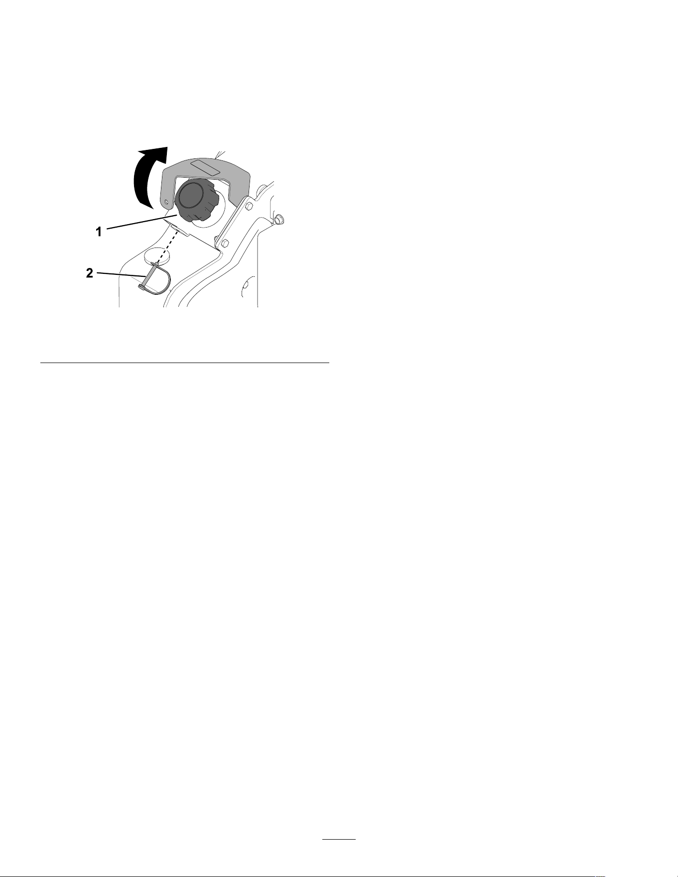
3. Remove the snapper pin and raise the bracket.
g367241
Figure 22
1. Fuel cap
2. Snapper pin
4. Remove the fuel cap.
5. Fill the tank with fuel up to the ller neck.
6. Install the cap.
7. Lower the bracket and secure it with the snapper
pin.
Performing Daily
Maintenance
Before starting the machine each day , perform the
Each Use/Daily procedures listed in Maintenance
( page 27 ) .
Important: Check the hydraulic-uid level
and bleed the fuel system before starting the
engine for the rst time; refer to Checking the
Hydraulic-Fluid Level ( page 50 ) and Bleeding the
Fuel System ( page 38 ) .
During Operation
During Operation Safety
General Safety
• Do not exceed the rated operating capacity , as the
machine may become unstable, which may result
in loss of control.
• Do not carry a load with the arms raised. Always
carry loads close to the ground.
• Use only T oro-approved attachments and
accessories. Attachments can change the stability
and the operating characteristics of the machine.
• For machines with a platform:
– Lower the loader arms before stepping of f the
platform.
– Do not try to stabilize the machine by putting
your foot on the ground. If you lose control of
the machine, step of f the platform and away
from the machine.
– Do not place your feet under the platform.
– Do not move the machine unless you are
standing with both feet on the platform and your
hands are holding onto the reference bars.
• Use your full attention while operating the
machine. Do not engage in any activity that
causes distractions; otherwise, injury or property
damage may occur .
• Look behind and down before backing up to
ensure that the path is clear .
• Never jerk the controls; use a steady motion.
• The owner/user can prevent and is responsible
for accidents that may cause personal injury or
property damage.
• W ear appropriate clothing including gloves, eye
protection, long pants, substantial slip-resistant
footwear , and hearing protection. T ie back long
hair and do not wear loose clothing or loose
jewelry .
• Do not operate the machine when you are tired, ill,
or under the inuence of alcohol or drugs.
• Never carry passengers and keep pets and
bystanders away from the machine.
• Operate the machine only in good light, keeping
away from holes and hidden hazards.
• Ensure that all the drives are in neutral and engage
the parking brake (if equipped) before starting the
engine. Start the engine only from the operator's
position.
• Use care when approaching blind corners, shrubs,
trees, or other objects that may obscure vision.
18

• Slow down and use caution when making turns
and crossing roads and sidewalks. W atch for
traf c.
• Stop the attachment when you are not working.
• Stop the machine, shut of f the engine, remove
the key , and inspect the machine if you strike
an object. Make any necessary repairs before
resuming operation.
• Never run an engine in an enclosed area.
• Never leave a running machine unattended.
• Before leaving the operating position, do the
following:
– Park the machine on a level surface.
– Lower the loader arms and disengage the
auxiliary hydraulics.
– Engage the parking brake (if equipped).
– Shut of f the engine and remove the key .
• Do not operate the machine when there is the risk
of lightning.
• Operate the machine only in areas where there is
suf cient clearance for you to safely maneuver .
Be aware of obstacles in close proximity to you.
Failure to maintain adequate distance from trees,
walls, and other barriers may result in injury as the
machine backs up during operation if you are not
attentive to the surroundings.
• Check for overhead clearance (i.e., electrical
wires, branches, and doorways) before driving
under any objects and do not contact them.
• Do not overll the attachment and always keep the
load level when raising the loader arms. Items in
the attachment could fall and cause injury .
Slope Safety
• Operate the machine up and down slopes with
the heavy end of the machine uphill. W eight
distribution changes with attachments. An empty
bucket makes the rear of the machine the heavy
end, and a full bucket makes the front of the
machine the heavy end. Most other attachments
make the front of machine the heavy end.
• Raising the loader arms on a slope af fects the
stability of the machine. Keep the loader arms in
the lowered position when on slopes.
• Slopes are a major factor related to loss of control
and tip-over accidents, which can result in severe
injury or death. Operating the machine on any
slope or uneven terrain requires extra caution.
• Establish your own procedures and rules for
operating on slopes. These procedures must
include surveying the site to determine which
slopes are safe for machine operation. Always
use common sense and good judgment when
performing this survey .
• Slow down and use extra care on hillsides. Ground
conditions can af fect the stability of the machine.
• A void starting or stopping on a slope. If the
machine loses traction, proceed slowly , straight
down the slope.
• A void turning on slopes. If you must turn, turn
slowly and keep the heavy end of the machine
uphill.
• Keep all movements on slopes slow and gradual.
Do not make sudden changes in speed or
direction.
• If you feel uneasy operating the machine on a
slope, do not do it.
• W atch for holes, ruts, or bumps, as uneven terrain
could overturn the machine. T all grass can hide
obstacles.
• Use caution when operating on wet surfaces.
Reduced traction could cause sliding.
• Evaluate the area to ensure that the ground is
stable enough to support the machine.
• Use caution when operating the machine near the
following:
– Drop-of fs
– Ditches
– Embankments
– Bodies of water
The machine could suddenly roll over if a track
goes over the edge or the edge caves in. Maintain
a safe distance between the machine and any
hazard.
• Do not remove or add attachments on a slope.
• Do not park the machine on a hillside or slope.
Utility Line Safety
• If you strike a utility line, do the following:
– Shut of f the machine and remove the key .
– Remove all individuals from the work area.
– Immediately contact the proper emergency and
utility authorities to secure the area.
– If you damage a ber-optic cable, do not look
into the exposed light.
• Do not leave the operator ’ s platform if the machine
is charged with electricity . Y ou will be safe as long
as you do not leave the platform.
– T ouching any part of the machine may ground
you.
– Do not allow another individual to touch or
approach the machine when charged.
19

– Always assume the machine is charged if you
strike an electrical or communication line. Do
not attempt to leave the machine.
• Leaking gas is both ammable and explosive and
may cause serious injury or death. Do not smoke
while operating the machine.
Starting the Engine
1. Ensure that the battery-disconnect switch is in
the O N position.
2. Ensure that the traction-control is in the N EUTRAL
position.
3. Move the throttle lever to the S LOW position.
4. Insert the key into the key switch and turn it to
the O N position.
5. W ait for the glow-plug indicator light to stop
blinking.
6. T urn the key to the S TART position. When the
engine starts, release the key .
Important: Do not engage the starter for
more than 10 seconds at a time. If the engine
fails to start, wait 30 seconds for the starter
to cool down between attempts. Failure to
follow these instructions could burn out the
starter motor .
7. Move the throttle lever to the F AST position.
8. Enable the traction control by toggling the
traction-enable switch before driving the
machine.
Starting in Cold W eather
If the outdoor temperature is below freezing, store
the traction unit in a garage to keep it warmer and to
aid in starting.
When starting the engine in cold conditions (i.e., when
the air temperature is at or below freezing), allow it to
run in the S LOW throttle position for 8 minutes before
moving the throttle to the F AST position or engaging
the auxiliary hydraulics.
Important: Running the engine at high speeds
when the hydraulic system is cold could damage
the hydraulic system.
Driving the Machine
Note: Enable the traction control by toggling the
traction-enable switch before driving the machine.
Use the traction control to move the machine. The
farther you move the traction control in any direction,
the faster the machine moves in that direction.
Release the traction control to stop the machine.
The throttle control regulates the engine speed as
measured in rpm (revolutions per minute). Place the
throttle lever in the F AST position for best performance.
Y ou can, however , use the throttle position to operate
at slower speeds.
Shutting Off the Engine
1. Park the machine on a level surface, engage
the parking brake (if equipped), and lower the
loader arms.
2. Ensure that the auxiliary hydraulics lever is in
the N EUTRAL position.
3. Move the throttle lever to the S LOW position.
4. If the engine has been working hard or is hot, let
it idle for a minute before turning the key switch
to the O FF position.
Note: This helps to cool the engine before you
shut it of f. In an emergency , you can shut of f
the engine immediately .
5. T urn the key switch to the O FF position and
remove the key .
CAUTION
A child or untrained bystander could attempt
to operate the traction unit and be injured.
Remove the key from the key switch when
leaving the traction unit, even if just for a few
seconds.
Using Attachments
Installing an Attachment
Important: Use only T oro-approved attachments.
Attachments can change the stability and the
operating characteristics of the machine. The
warranty of the machine may be voided if you use
the machine with unapproved attachments.
Important: Before installing the attachment,
ensure that the mount plates are free of any dirt or
debris and that the pins rotate freely . If the pins
do not rotate freely , grease them.
20
1. Position the attachment on a level surface with
enough space behind it to accommodate the
machine.
2. Start the engine.
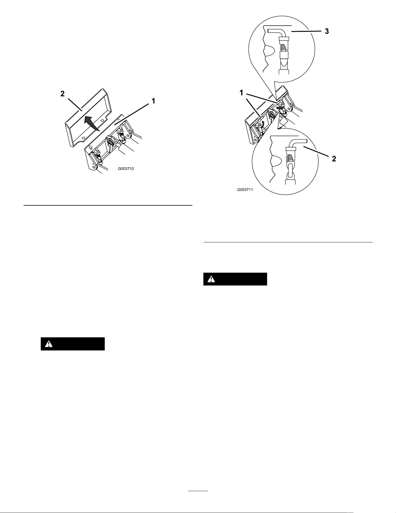
3. T ilt the attachment mount plate forward.
4. Position the mount plate into the upper lip of the
attachment receiver plate.
g003710
Figure 23
1. Mount plate 2. Receiver plate
5. Raise the loader arms while tilting back the
mount plate at the same time.
Important: Raise the attachment enough to
clear the ground and tilt the mount plate all
the way back.
6. Shut of f the engine and remove the key .
7. Engage the quick-attach pins, ensuring that they
are fully seated in the mount plate.
Important: If the pins do not rotate to the
engaged position, the mount plate is not
fully aligned with the holes in the attachment
receiver plate. Check the receiver plate and
clean it if necessary .
W ARNING
If you do not fully seat the quick-attach
pins through the attachment mount plate,
the attachment could fall off the machine,
crushing you or bystanders.
Ensure that the quick-attach pins are fully
seated in the attachment mount plate.
g00371 1
Figure 24
1. Quick-attach pins
(engaged position)
3. Engaged position
2. Disengaged position
Connecting the Hydraulic Hoses
W ARNING
Hydraulic uid escaping under pressure can
penetrate skin and cause injury . Fluid injected
into the skin must be surgically removed
within a few hours by a doctor familiar with
this form of injury; otherwise, gangrene could
result.
• Ensure that all hydraulic-uid hoses
and lines are in good condition and all
hydraulic connections and ttings are tight
before applying pressure to the hydraulic
system.
• Keep your body and hands away from
pinhole leaks or nozzles that eject
high-pressure hydraulic uid.
• Use cardboard or paper to nd hydraulic
leaks; never use your hands.
21

CAUTION
Hydraulic couplers, hydraulic lines and
valves, and hydraulic uid may be hot.
Contact with hot components could cause a
burn, resulting in minor or moderate injury .
• W ear gloves when operating the hydraulic
couplers.
• Allow the machine to cool before touching
hydraulic components.
• Do not touch hydraulic uid spills.
If the attachment requires hydraulics for operation,
connect the hydraulic hoses as follows:
1. Shut of f the engine.
2. T urn the key to the R UN position, but do not start
the machine.
3. Press the auxiliary hydraulic control switch back
and forth to relieve pressure at the hydraulic
couplers.
4. T urn the key to the O FF position and remove it.
5. Remove the protective covers from the hydraulic
connectors on the machine.
6. Ensure that all foreign matter is cleaned from
the hydraulic connectors.
7. Push the attachment male connector into the
female connector on the machine.
Note: When you connect the attachment male
connector rst, you relieve any pressure built
up in the attachment.
8. Push the attachment female connector onto the
male connector on the machine.
9. Conrm that the connection is secure by pulling
on the hoses.
Removing an Attachment
1. Park the machine on a level surface.
2. Lower the attachment to the ground.
3. Shut of f the engine and remove the key .
4. Disengage the quick-attach pins by turning them
to the outside.
5. If the attachment uses hydraulics, do the
following:
A. T urn the key to the R UN position, but do not
start the machine.
B. Press the auxiliary hydraulic control switch
back and forth to relieve pressure at the
hydraulic couplers.
C. T urn the key to the O FF position and remove
it.
D. Slide the collars back on the hydraulic
couplers and disconnect them.
Important: Connect the attachment
hoses together to prevent hydraulic
system contamination during storage.
E. Install the protective covers onto the
hydraulic couplers on the machine.
6. Start the engine, tilt the mount plate forward, and
back the machine away from the attachment.
After Operation
After Operation Safety
General Safety
• Engage the parking brake (if equipped), lower
the loader arms, shut of f the engine, remove the
key , wait for all movement to stop, and allow the
machine to cool before adjusting, cleaning, storing,
or servicing it.
• Clean debris from the attachments, drives,
muf ers, and engine to help prevent res. Clean
up oil or fuel spills.
• Keep all parts in good working condition and all
hardware tightened.
• Do not touch parts that may be hot from operation.
Allow them to cool before attempting to maintain,
adjust, or service the machine.
• Use care when loading or unloading the machine
into a trailer or truck.
22
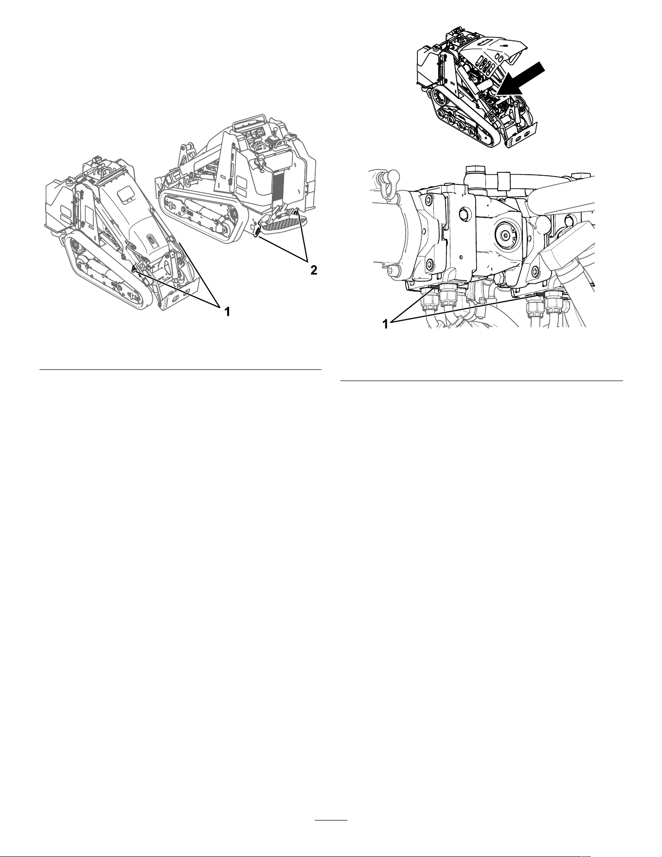
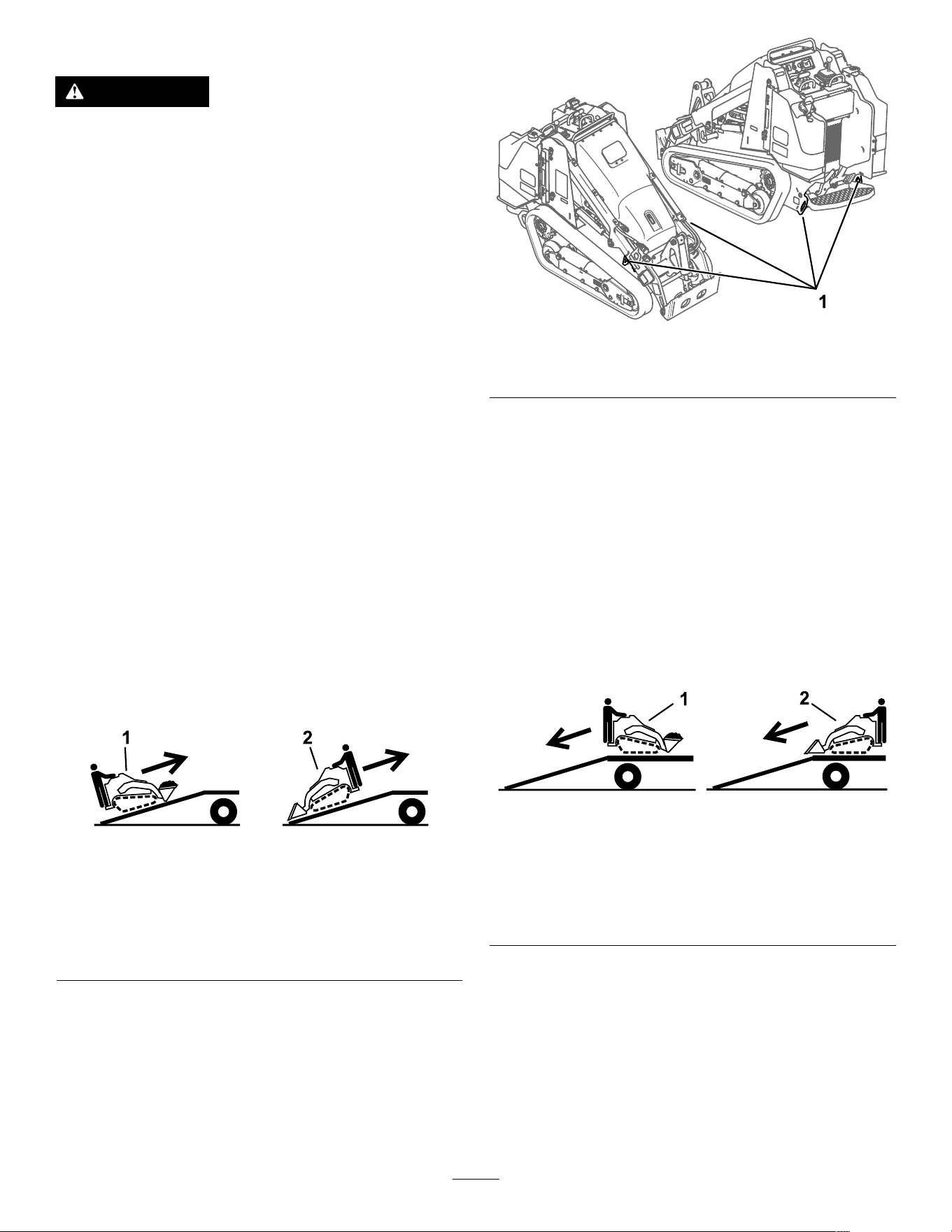
Retrieving a Stuck Machine
If the machine becomes stuck (e.g., in muddy
conditions), pull the machine back into a stable
position using either both front tie-down/lift points or
both rear tie-down points simultaneously .
g41 1228
Figure 25
1. Front tie-down/lift points
2. Rear tie-down points
Moving a Non-Functioning
Machine
Important: Do not tow or pull the machine
without rst opening the tow valves, or you will
damage the hydraulic system.
1. Shut of f the engine and remove the key .
2. Open the hood and secure the hood prop.
3. Using a wrench, turn the tow valves on the
hydraulic pumps twice counterclockwise.
g357135
g365261
Figure 26
1. T ow valve
4. Disengage the parking brake.
5. T ow the machine as required.
6. After repairing the machine, close the tow valves
before operating it.
23
Hauling the Machine
Use a heavy-duty trailer or truck to haul the machine.
Use a full-width ramp. Ensure that the trailer or truck
has all the necessary brakes, lighting, and marking as
required by law . Please carefully read all the safety
instructions. Knowing this information could help
you or bystanders avoid injury . Refer to your local
ordinances for trailer and tie-down requirements.
W ARNING
Driving on the street or roadway without
turn signals, lights, reective markings, or a
slow-moving-vehicle emblem is dangerous
and can lead to accidents causing personal
injury .
Do not drive the machine on a public street
or roadway .
Selecting a T railer
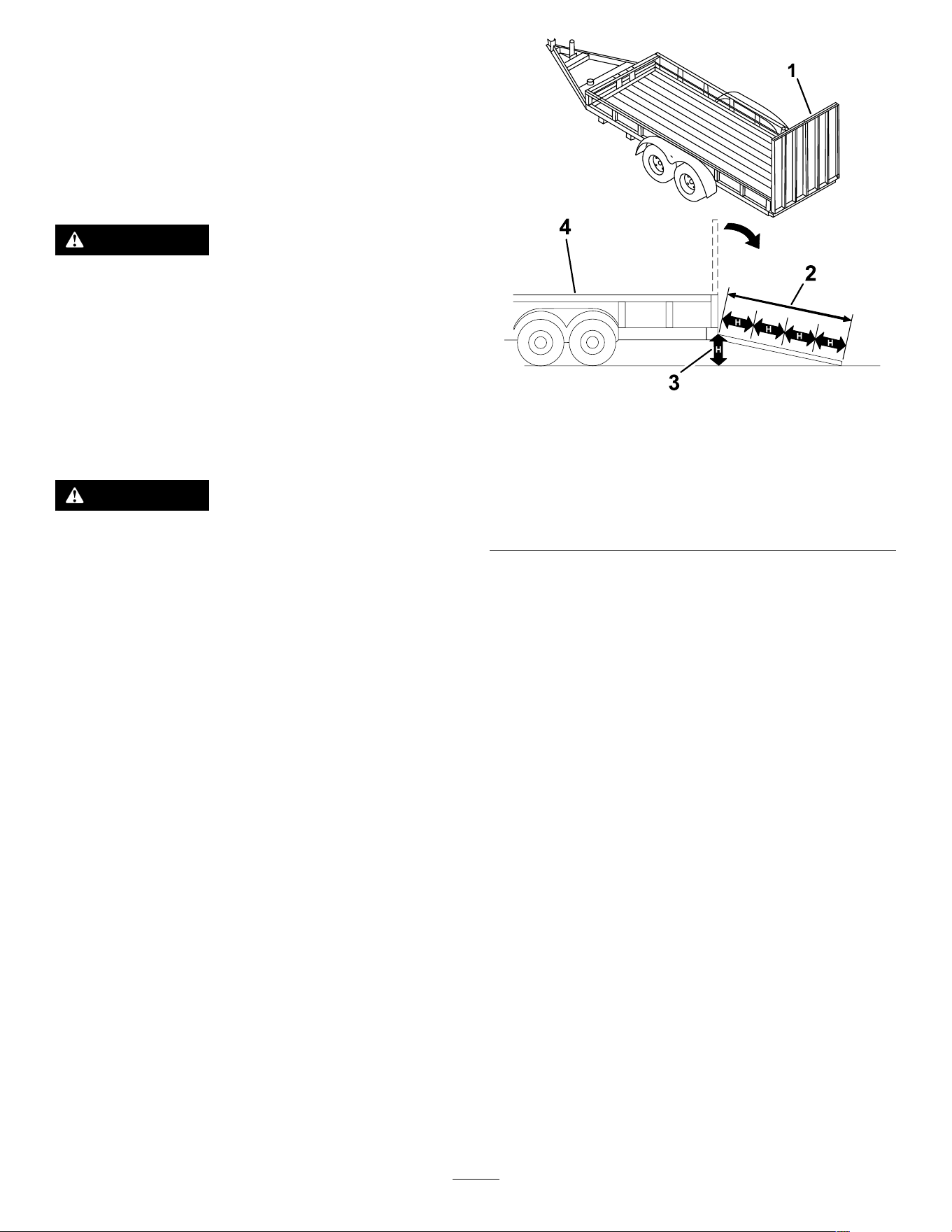
W ARNING
Loading a machine onto a trailer or truck
increases the possibility of tip-over and could
cause serious injury or death ( Figure 27 ).
• Use only full-width ramps.
• Ensure that the length of ramp is at least 4
times as long as the height of the trailer or
truck bed to the ground. This ensures that
ramp angle does not exceed 15 degrees on
at ground.
g229507
Figure 27
1. Full-width ramp(s) in
stowed position
3. H=height of the trailer or
truck bed to the ground
2. Ramp is at least 4 times
as long as the height of
the trailer or truck bed to
the ground
4. T railer
24
Loading the Machine
W ARNING
Loading or unloading a machine onto a trailer
or truck increases the possibility of tip-over
and could cause serious injury or death.
• Use extreme caution when operating a
machine on a ramp.
• Load and unload the machine with the
heavy end up the ramp.
• A void sudden acceleration or deceleration
while driving the machine on a ramp as
this could cause a loss of control or a
tip-over situation.
1. If using a trailer , connect it to the towing vehicle
and connect the safety chains.
2. If applicable, connect the trailer brakes.
3. Lower the ramp(s).
4. Lower the loader arms.
5. Load the machine onto the trailer with the heavy
end up the ramp, carrying loads low , as shown.
• If the machine has a full load-bearing
attachment (e.g., bucket) or a
non-load-bearing attachment (e.g.,
trencher), drive the machine forward up the
ramp.
• If the machine has an empty load-bearing
attachment or no attachment, back the
machine up the ramp.
g204457
Figure 28
1. Machine with full
attachment or
non-load-bearing
attachment—drive the
machine forward up the
ramp(s).
2. Machine with empty or
no attachment—back the
machine up the ramp(s).
6. Lower the loader arms all the way down.
7. Engage the parking brake (if equipped), shut of f
the engine, and remove the key .
8. Use the metal tie-down loops on the machine
to securely fasten the machine to the trailer or
truck with straps, chains, cable, or ropes. Refer
to local regulations for tie-down requirements.
g41 1229
Figure 29
1. T ie-down loops
Unloading the Machine
1. Lower the ramp(s).
2. Unload the machine from the trailer with the
heavy end up the ramp, carrying loads low .
• If the machine has a full load-bearing
attachment (e.g., bucket) or a
non-load-bearing attachment (e.g.,
trencher), back it down the ramp.
• If the machine has an empty load-bearing
attachment or no attachment, drive it forward
down the ramp.
g204458
Figure 30
1. Machine with full
attachment or
non-load-bearing
attachment—back the
machine down the
ramp(s).
2. Machine with empty or
no attachment—drive the
machine forward down the
ramp(s).
25
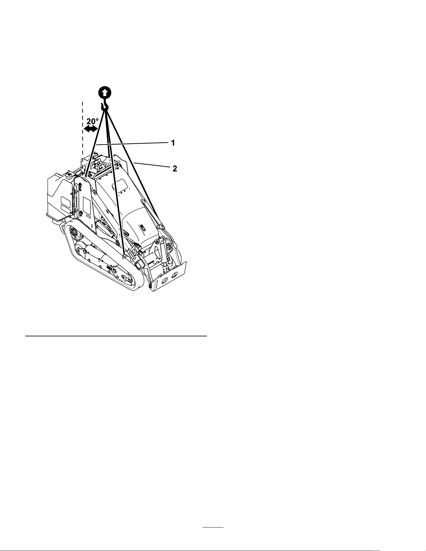
Lifting the Machine
Remove any attachments and lift the machine using
the 4 lift points.
Do not exceed a 20-degree angle when lifting the
machine; use the minimum chain lengths provided
below .
g377831
Figure 31
1. Chain length for rear lift point (2)—1 18.9 cm (46.8 inches)
2. Chain length for front lift point (2)—206.2 cm (81.2 inches)
26

Maintenance
Note: Determine the left and right sides of the machine from the normal operating position.
Maintenance Safety
CAUTION
If you leave the key in the switch, someone could accidently start the engine and seriously
injure you or other bystanders.
Remove the key from the switch before you perform any maintenance.
• Park the machine on a level surface, disengage
the auxiliary hydraulics, lower the attachment,
engage the parking brake (if equipped), shut
of f the engine, and remove the key . W ait for all
movement to stop and allow the machine to cool
before adjusting, cleaning, storing, or repairing it.
• Clean up oil or fuel spills.
• Do not allow untrained personnel to service the
machine.
• Use jack stands to support the components when
required.
• Carefully release pressure from components
with stored energy; refer to Relieving Hydraulic
Pressure ( page 49 ) .
• Disconnect the battery before making any repairs;
refer to Using the Battery-Disconnect Switch ( page
38 ) .
• Keep your hands and feet away from the moving
parts. If possible, do not make adjustments with
the engine running.
• Keep all parts in good working condition and all
hardware tightened. Replace all worn or damaged
decals.
• Do not tamper with the safety devices.
• Use only T oro-approved attachments.
Attachments can change the stability and the
operating characteristics of the machine. Y ou may
void the warranty if you use the machine with
unapproved attachments.
• Use only genuine T oro replacement parts.
• If any maintenance or repair requires the loader
arms to be in the raised position, secure the arms
in the raised position with the hydraulic-cylinder
lock(s).
Recommended Maintenance Schedule(s)
Maintenance Service
Interval
Maintenance Procedure
After the rst 8 hours
• Check and adjust the track tension.
• Replace the hydraulic lter .
After the rst 50 hours
• Check and adjust the track tension.
Before each use or daily
• Grease the machine. (Grease immediately after every washing.)
• Check the air-lter-service indicator .
• Check the engine-oil level.
• Drain water and other contaminants from the water separator .
• Clean the tracks and check for excessive wear and proper tension.
• Clean the screen, oil cooler , and front of the radiator (more often in dirty or dusty
conditions).
• Check and clean the radiator screen
• Check the coolant level in the expansion tank.
• T est the parking brake.
• Check the alternator-belt condition and tension.
• Remove debris from the machine.
• Check for loose fasteners.
Every 25 hours
• Remove the air-cleaner cover , clean out debris, and check the air-lter-service
indicator .
• Check the hydraulic-uid level.
27

Maintenance Service
Interval
Maintenance Procedure
Every 50 hours
• Check the battery condition.
• Check and adjust the track tension.
Every 100 hours
• Check the cooling system hoses.
• Check the hydraulic lines for leaks, loose ttings, kinked lines, loose mounting
supports, wear , weather , and chemical deterioration.
• Check for dirt buildup in the chassis.
Every 250 hours
• Change the engine oil and lter . (Service more frequently if conditions are extremely
dusty or sandy .)
• Replace the hydraulic lter .
Every 400 hours
• Check the fuel lines and connections for deterioration, damage, or loose connections.
Every 500 hours
• Replace the water separator lter .
• Replace the in-line fuel lter
• Change the engine coolant.
• Replace the alternator belt. (Refer to the engine owner ’ s manual for instructions.)
• Change the hydraulic uid.
Every 600 hours
• Replace the safety air lter .
Every 1,500 hours or
2 years, whichever
comes rst
• Replace all moving hydraulic hoses.
Y early or before storage
• Check and adjust the track tension.
• T ouch up chipped paint.
Every 2 years
• Drain and clean the fuel tank(s)—Authorized Service Dealer only .
Important: Refer to your engine owner ’ s manual for additional maintenance procedures.
28
Pre-Maintenance
Procedures
Using the Cylinder Locks
W ARNING
The loader arms may lower when in the raised
position, crushing anyone under them.
Install the cylinder lock(s) before performing
maintenance that requires raised loader arms.
Installing the Cylinder Locks
1. Remove the attachment.
2. If needed, open the hood and secure the prop
rod.
Note: Y ou cannot open the hood after raising
the loader arms.
3. Raise the loader arms to the fully raised position.
4. Shut of f the engine and remove the key .
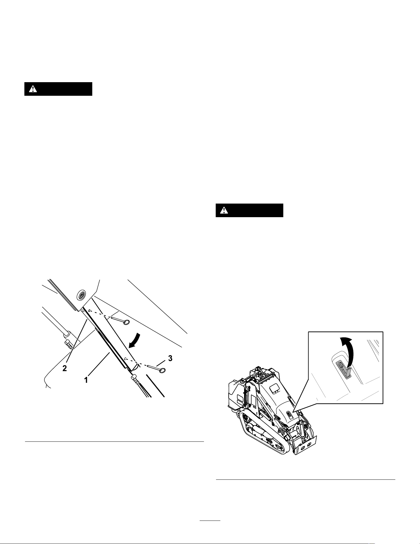
5. Remove the 2 pins securing the cylinder lock to
the posts on the side of the machine.
6. Slide the cylinder lock over the lift-cylinder rod.
g365284
Figure 32
1. Cylinder lock 3. Pin (2)
2. Lift-cylinder rod
7. Repeat step 5 and 6 for the other side of the
machine.
8. Slowly lower the loader arms until the cylinder
locks contact the cylinder bodies and rod ends.
Removing and Storing the
Cylinder Locks
Important: Remove the cylinder locks from the
rods and fully secure them in the storage position
before operating the machine.
1. Start the engine.
2. Raise the loader arms to the fully raised position.
3. Shut of f the engine and remove the key .
4. Remove the pins securing the cylinder locks.
5. Place the cylinder locks on the posts on the
sides of the machine and secure with the pins.
6. Lower the loader arms.
7. If the hood is open, close it.
Accessing Internal
Components
W ARNING
Opening or removing covers, hoods, and
screens while the engine is running could
allow you to contact moving parts, seriously
injuring you.
Before opening any of the covers, hoods, and
screens, shut off the engine, remove the key
from the key switch, and allow the engine to
cool.
Opening the Hood
1. Use the latch key to unlock the lever .
g365296
Figure 33
2. Use the lever to lift open the hood
3. Secure the prop rod.
29
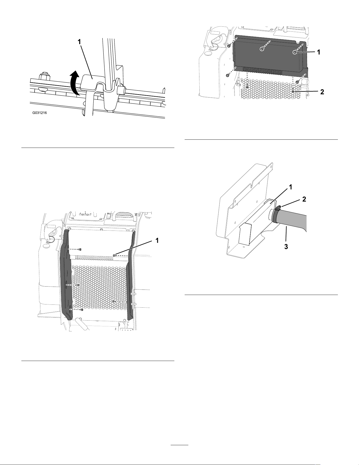
Closing the Hood
1. Lift up on the tab securing the prop rod.
g031216
Figure 34
1. Prop-rod tab
2. Lower the hood and secure it by pushing down
on the front of the hood until it locks in place.
3. Use the latch key to secure the latch.
Removing the Console Plate
1. Remove the 2 side cushions.
g367613
Figure 35
1. Hex-washer head bolt—5/16 x 1/2 inch (5)
2. Remove the console plate.
g367612
Figure 36
1. Hex-washer head
bolt—3/8 x 1 inch (5)
2. Hex-washer head
bolt—5/16 x 3/4 inch
(2)
3. Loosen the hose clamp on the hose and
disconnect the hose from the air box.
g435167
Figure 37
1. Air box 3. Hose
2. Hose clamp
30
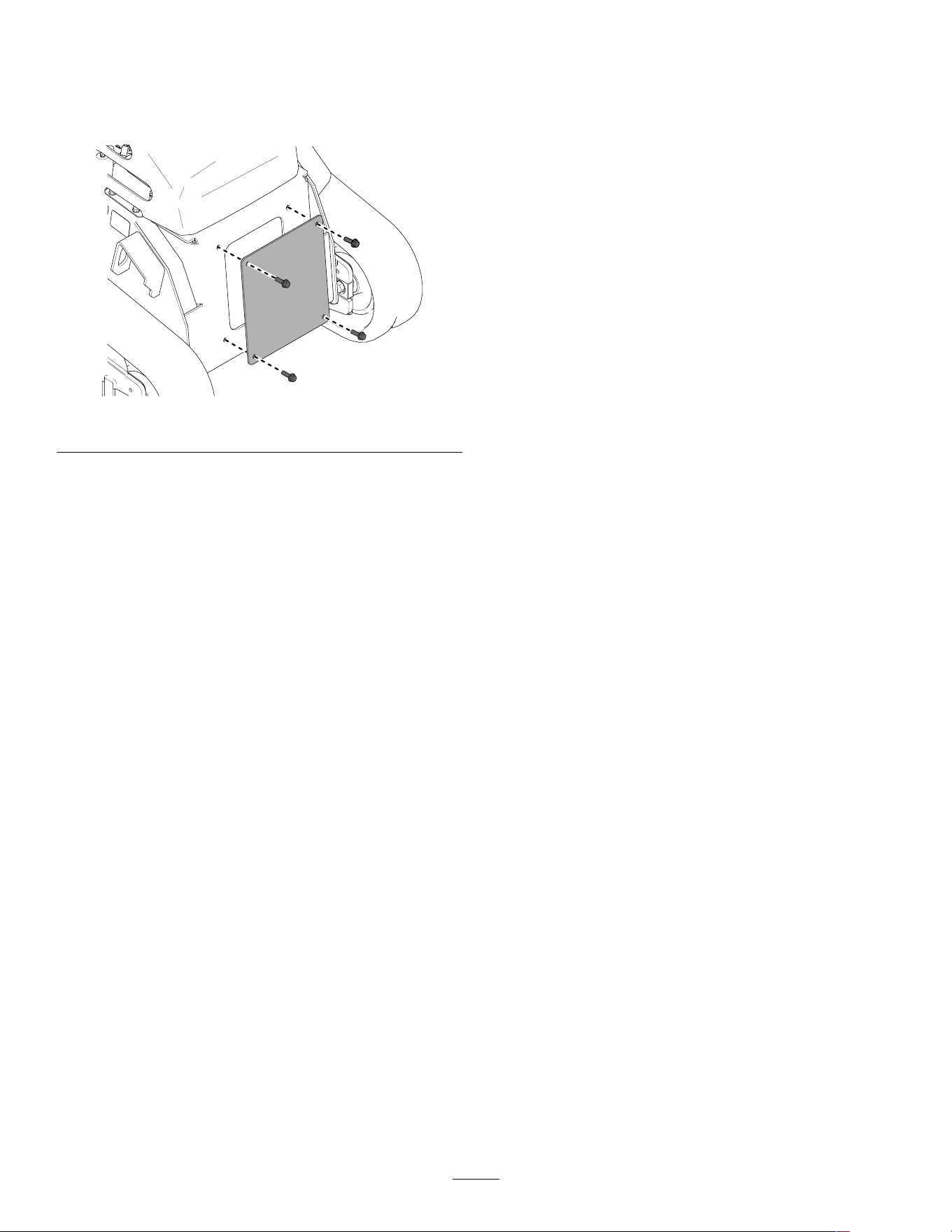
Removing the Front Cover
1. Raise the loader arms and secure with the
cylinder locks.
2. Remove the front cover .
g365300
Figure 38
31
Lubrication
Greasing the Machine
Service Interval : Before each use or daily (Grease
immediately after every washing.)
Grease T ype: General-purpose grease.
1. Park the machine on a level surface, engage the
parking brake, and lower the loader arms.
2. Shut of f the engine and remove the key .
3. Clean the grease ttings with a rag.
g435269
Figure 39
4. Connect a grease gun to each tting.
5. Pump grease into the ttings until grease begins
to ooze out of the bearings (approximately 3
pumps).
6. Wipe up any excess grease.
Engine Maintenance
Engine Safety
• Shut of f the engine before checking the oil or
adding oil to the crankcase.
• Do not change the engine governor setting or
overspeed the engine.
• Keep your hands, feet, face, other body parts,
and clothing away from the muf er and other hot
surfaces.
Servicing the Air-Cleaner
Service Interval : Before each use or daily —Check
the air-lter-service indicator .
Every 25 hours —Remove the air-cleaner cover ,
clean out debris, and check the air-lter-service
indicator .
Every 600 hours —Replace the safety air lter .
Important: T o prevent engine damage, always
operate the engine with the air lter and cover
installed.
Important: Replace the primary air-cleaner
lter only when the service indicator shows red.
Changing the air lter before it is necessary only
increases the chance of dirt entering the engine
when you remove the lter .
Servicing the Air-Cleaner Cover
and Body
g367365
Figure 40
1. Park the machine on a level surface, engage the
parking brake, and lower the loader arms.
2. Open the hood and secure the prop rod.
Note: Y ou cannot open the hood after raising
the loader arms.
32
3. Raise the loader arms enough to access the air
cleaner cover and lters.
4. Shut of f the engine and remove the key .
5. Check the air-cleaner body for damage that
could cause an air leak. Check the whole intake
system for leaks, damage, or loose hose clamps.
Replace or repair any damaged components.
6. Release the latches on the air cleaner cover and
pull the cover of f.
Important: Do not remove the air lter .
g367366
Figure 41
1. Dust cap 2. Filter
7. Squeeze the dust cap sides to open it and knock
the dust out.
8. Clean the inside of the cover with compressed
air that is under 205 kPa (30 psi).
Important: Do not use compressed air on
the air-cleaner body .
9. Check the service indicator .
• If the service indicator is clear , install the
cover with the dust cap oriented downward
and secure the latches.
• If the service indicator is red, replace the air
lter .
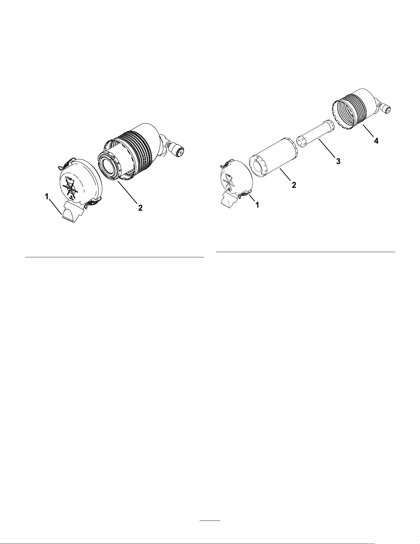
Replacing the Filter(s)
1. Gently slide the primary lter out of the
air-cleaner body .
Note: A void knocking the lter into the side of
the body .
Important: Do not attempt to clean the lter .
g435274
Figure 42
1. Air-cleaner cover
3. Safety lter
2. Primary lter 4. Air-lter body
2. If replacing the safety lter , gently slide the
primary lter out of the air-cleaner body .
3. Inspect the new lter(s) for tears, an oily lm, or
damage to the rubber seal. Look into the lter
while shining a bright light on the outside of the
lter; holes in the lter appear as bright spots.
If the lter is damaged, do not use it.
4. Carefully install the lter(s).
Note: Ensure that each lter is fully seated
by pushing on the outer rim of the lter while
installing it.
Important: Do not press on the soft inside
area of the lter .
5. Install the air-cleaner cover with the dust cap
oriented downward as shown in Figure 41 and
secure the latches.
6. Close the hood.
7. Lower the loader arms.
33
Servicing the Engine Oil
Service Interval : Before each use or daily —Check
the engine-oil level.
Every 250 hours —Change the engine oil and
lter . (Service more frequently if conditions are
extremely dusty or sandy .)
Engine-Oil Specications
The engine ships with oil in the crankcase; however ,
check the oil level before and after you rst start
the engine. Check the oil level before operating the
machine each day or each time you use the machine.
Crankcase capacity: 3.4 L (3.6 qt) with the lter
Preferred engine oil: T oro Premium Engine Oil
If using an alternate oil, use high-quality , low-ash
engine oil that meets or exceeds the following
specications:
• API service category CJ-4 or higher
• ACEA service category E6
• JASO service category DH-2
Important: Using engine oil other than API
classication CJ-4 or higher , ACEA E6, or JASO
DH-2 may cause the diesel particulate lter to plug
or cause engine damage.
Use the following engine oil viscosity grade:
• SAE 10W -30 (all temperatures)
• SAE 15W -40 (above 0° F)
Note: T oro Premium Engine oil is available from your
Authorized Service Dealer .
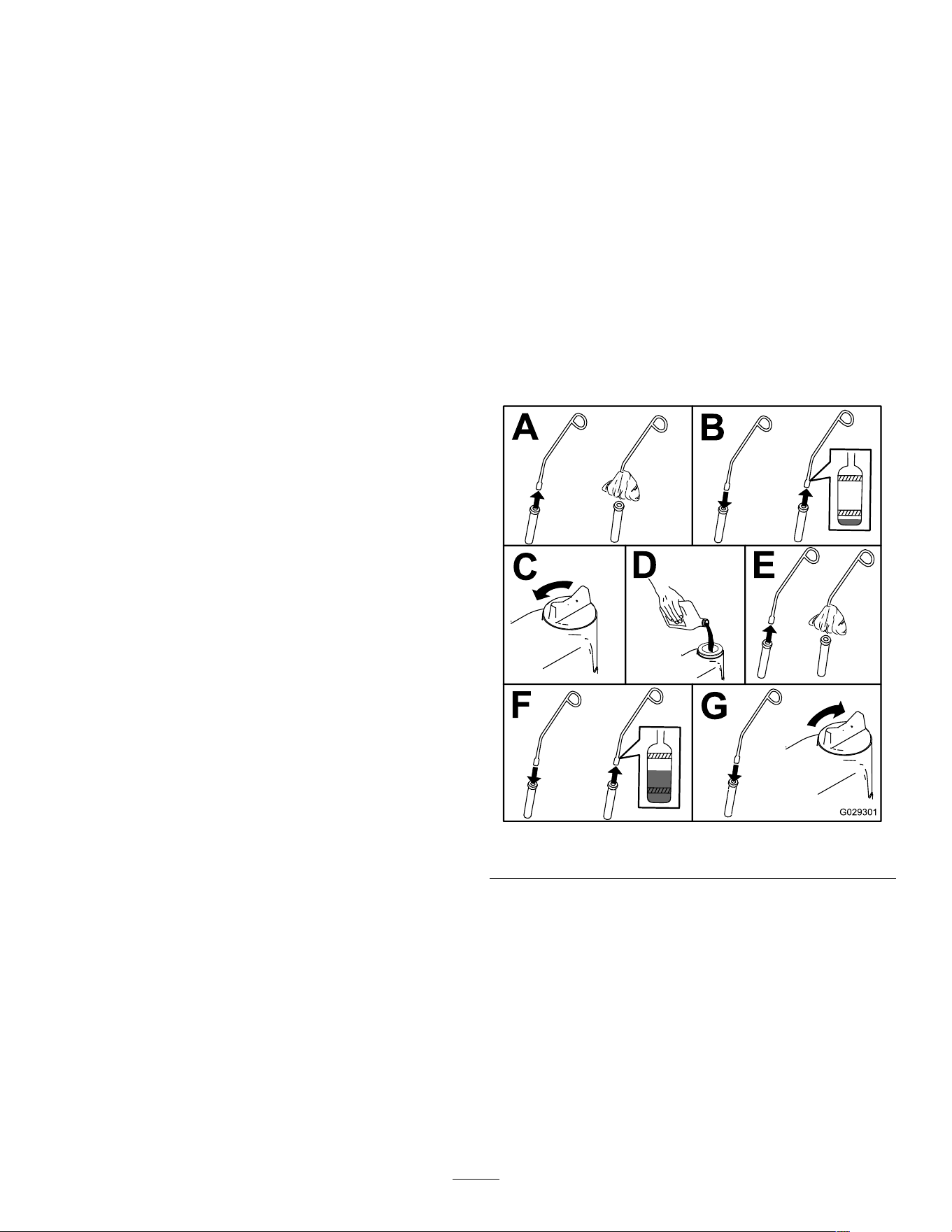
Checking the Engine-Oil Level
1. Park the machine on a level surface, engage the
parking brake, and lower the loader arms.
2. Open the hood and secure the prop rod.
Note: Y ou cannot open the hood after raising
the loader arms.
3. Raise the loader arms and secure them with the
cylinder locks.
4. Shut of f the engine, remove the key , and allow
the engine to cool.
5. Check the oil and add additional oil as needed.
Important: Do not overll the crankcase
with oil; if the oil in the crankcase is too high
and you run the engine, you may damage the
engine.
g029301
Figure 43
6. Remove the cylinder locks and lower the loader
arms.
7. Close the hood.
34
Changing the Engine Oil and Filter
1. Start the engine and let it run for 5 minutes.
Note: This warms the oil so that it drains better .
2. Park the machine on a level surface, engage the
parking brake, and lower the loader arms.
3. Open the hood and secure the prop rod.
Note: Y ou cannot open the hood after raising
the loader arms.
4. Raise the loader arms and secure them with the
cylinder locks.
5. Shut of f the engine and remove the key .
6. Drain the oil beneath the platform.
CAUTION
Components will be hot if the machine
has been running. If you touch hot
components, you may be burned.
Use care to avoid touching hot
components while changing the oil
and/or lter .
g41 1226
g360882
Figure 44
7. T orque the drain plug to 46 to 56 N∙m (34 to 42
ft-lb).
8. Place a shallow pan or rag under the lter to
catch oil.
9. Change the oil lter as shown.
35
g027477
Figure 45
10. Remove the oil-ll cap and slowly pour
approximately 80% of the specied amount of oil
in through the valve cover .
1 1. Check the oil level.
12. Slowly add additional oil to bring the level to the
upper hole on the dipstick.
13. Replace the ll cap.
14. Remove the cylinder locks and lower the loader
arms.
15. Close the hood.
Fuel System
Maintenance
DANGER
In certain conditions, fuel is extremely
ammable and highly explosive. A re or
explosion from fuel can burn you and others
and can damage property .
Refer to Fuel Safety ( page 17 ) for a complete
list of fuel related precautions.
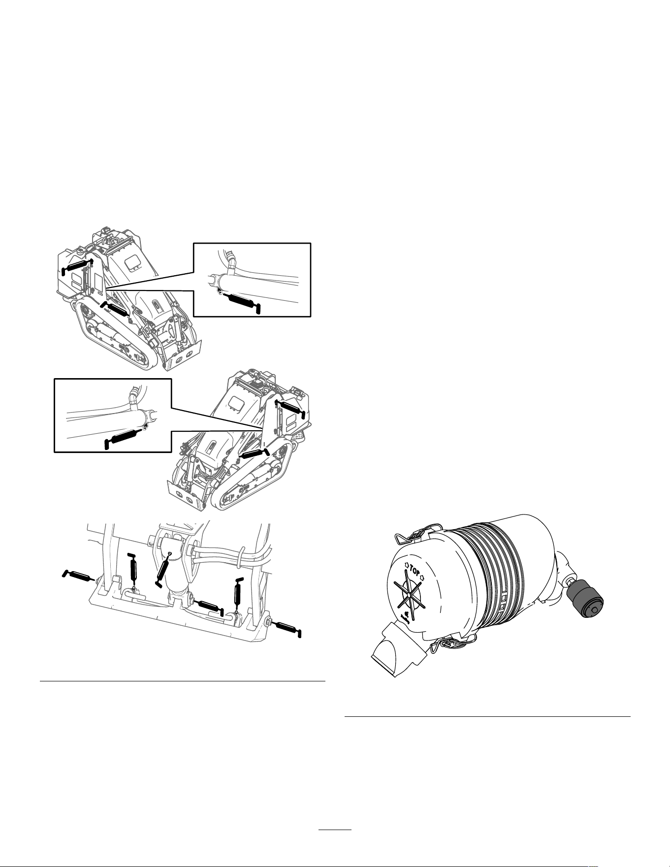
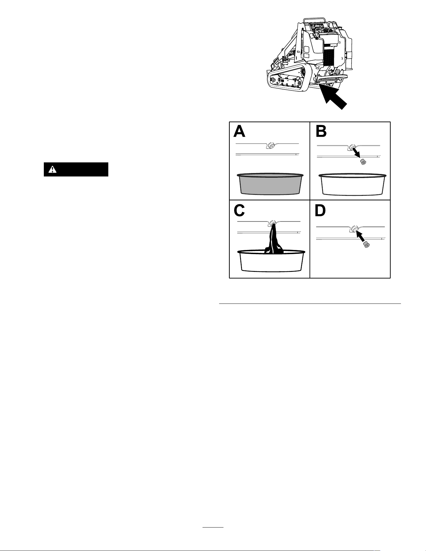
Draining the W ater
Separator
Service Interval : Before each use or daily
1. Park the machine on a level surface, engage the
parking brake, and lower the loader arms.
2. Shut of f the engine and remove the key .
3. Open the hood.
4. Place a clean container under the water
separator .
g365558
Figure 46
1. W ater separator 2. Drain valve
5. Loosen the drain valve on the bottom of the lter
canister and allow the water to drain.
6. When nished, tighten the drain valve.
7. Close the hood.
36
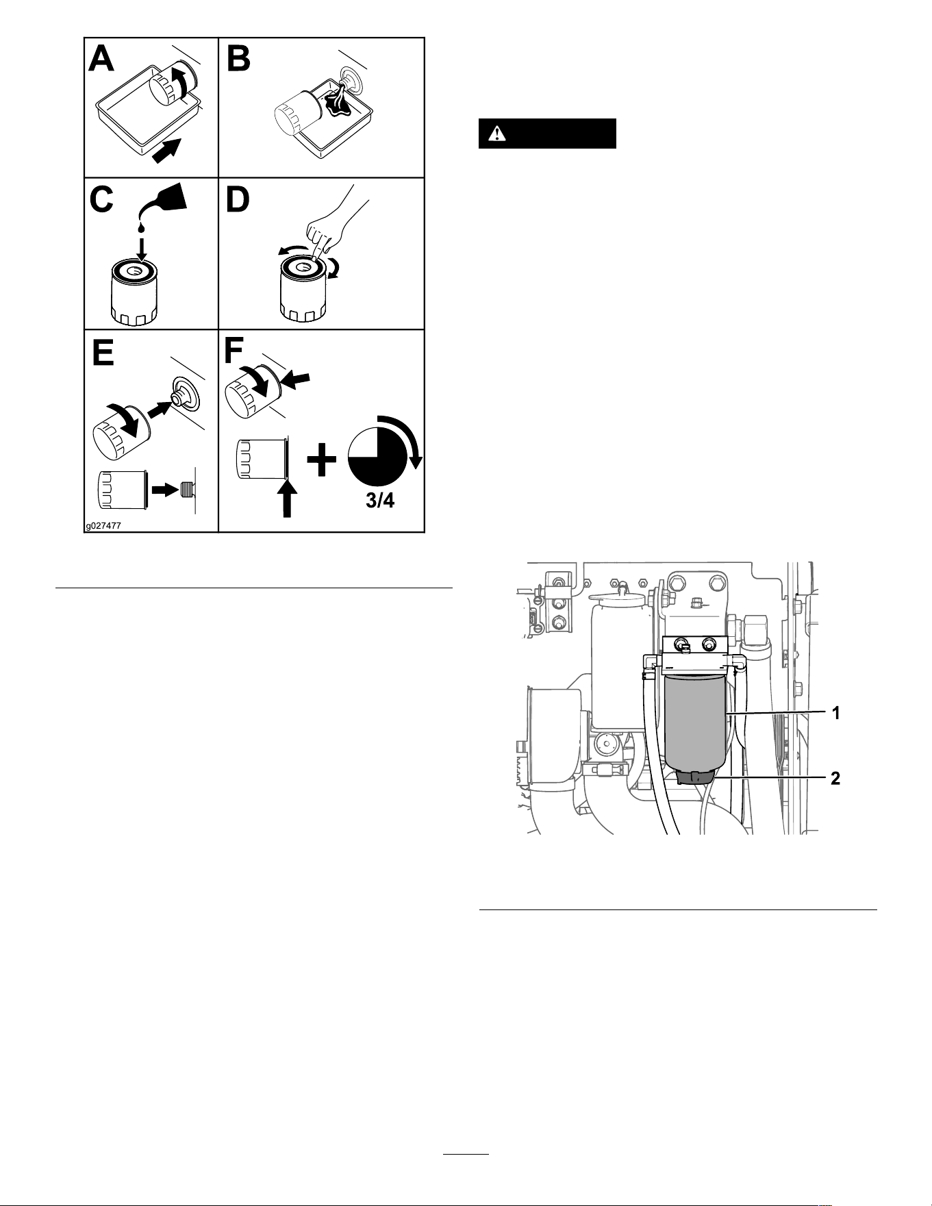
Replacing the W ater
Separator Filter
Service Interval : Every 500 hours
1. Park the machine on a level surface, engage the
parking brake, and lower the loader arms.
2. Shut of f the engine and remove the key .
3. Open the hood.
4. Clean the area where the lter canister mounts.
g365572
Figure 47
1. W ater separator
5. Remove the lter canister and clean the
mounting surface.
6. Lubricate the gasket on the new lter canister
with clean oil.
7. Fill the canister with fuel.
8. Install the lter canister by hand until the gasket
contacts the mounting surface, then rotate it an
additional 1/2 turn .
9. Close the hood.
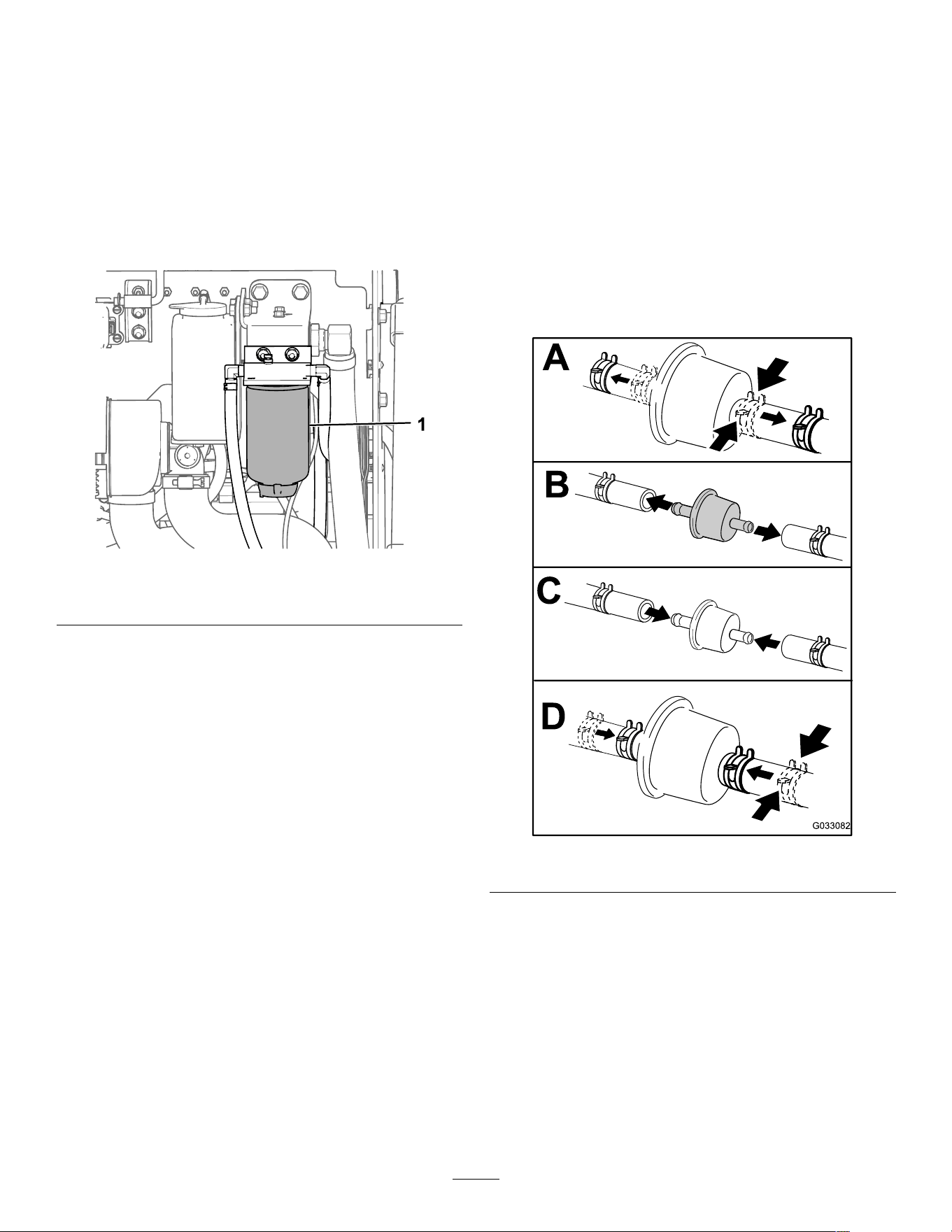
Replacing the In-Line Fuel
Filter
Service Interval : Every 500 hours
1. Park the machine on a level surface, engage the
parking brake, and lower the loader arms.
2. Shut of f the engine and remove the key .
3. Remove the console plate; refer to Removing
the Console Plate ( page 30 ) .
4. Replace the lter as shown.
Note: Ensure that the markings on the lter
follow the fuel ow direction.
g033082
Figure 48
Checking the Fuel Lines
and Connections
Service Interval : Every 400 hours/Y early (whichever
comes rst)
Inspect the fuel lines and connections for deterioration,
damage, or loose connections. T ighten any loose
connections and contact your Authorized Service
Dealer for assistance in xing damaged fuel lines.
37
Bleeding the Fuel System
Y ou must bleed the fuel system before starting the
engine if any of the following situations have occurred:
• Initial startup of a new machine
• The engine has ceased running due to a lack of
fuel.
• Maintenance has been performed upon
fuel-system components (e.g., lter replaced).
1. T urn the key to the RUN position.
2. Let the fuel pump run for 2 minutes prior to
starting the machine.
Draining the Fuel T ank(s)
Service Interval : Every 2 years
Have an Authorized Service Dealer drain and clean
the fuel tank(s).
Electrical System
Maintenance
Electrical System Safety
• Disconnect the battery before making any repairs;
refer to Using the Battery-Disconnect Switch ( page
38 ) .
• Charge the battery in an open, well-ventilated
area, away from sparks and ames. Unplug the
charger before connecting or disconnecting the
battery . W ear protective clothing and use insulated
tools.
• Battery acid is poisonous and can cause burns.
A void contact with skin, eyes, and clothing. Protect
your face, eyes, and clothing when working with a
battery .
• Battery gases can explode. Keep cigarettes,
sparks, and ames away from the battery .
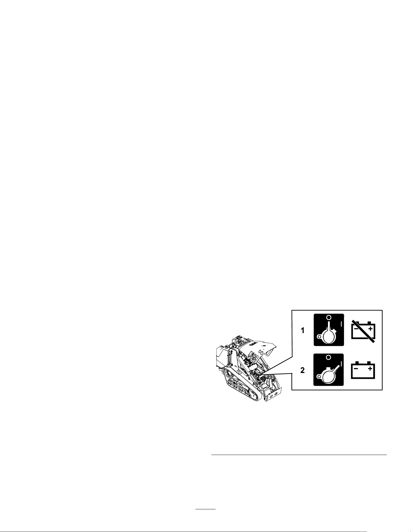
Using the
Battery-Disconnect Switch
1. Park the machine on a level surface, engage the
parking brake, and lower the loader arms.
2. Shut of f the engine and remove the key .
3. Open the hood.
4. T urn the battery-disconnect switch to the O N or
O FF position.
g365602
Figure 49
1. De-energize the
machine—rotate the
battery-disconnect switch
to the O FF position.
2. Energize the
machine—rotate the
battery-disconnect switch
to the O N position.
38
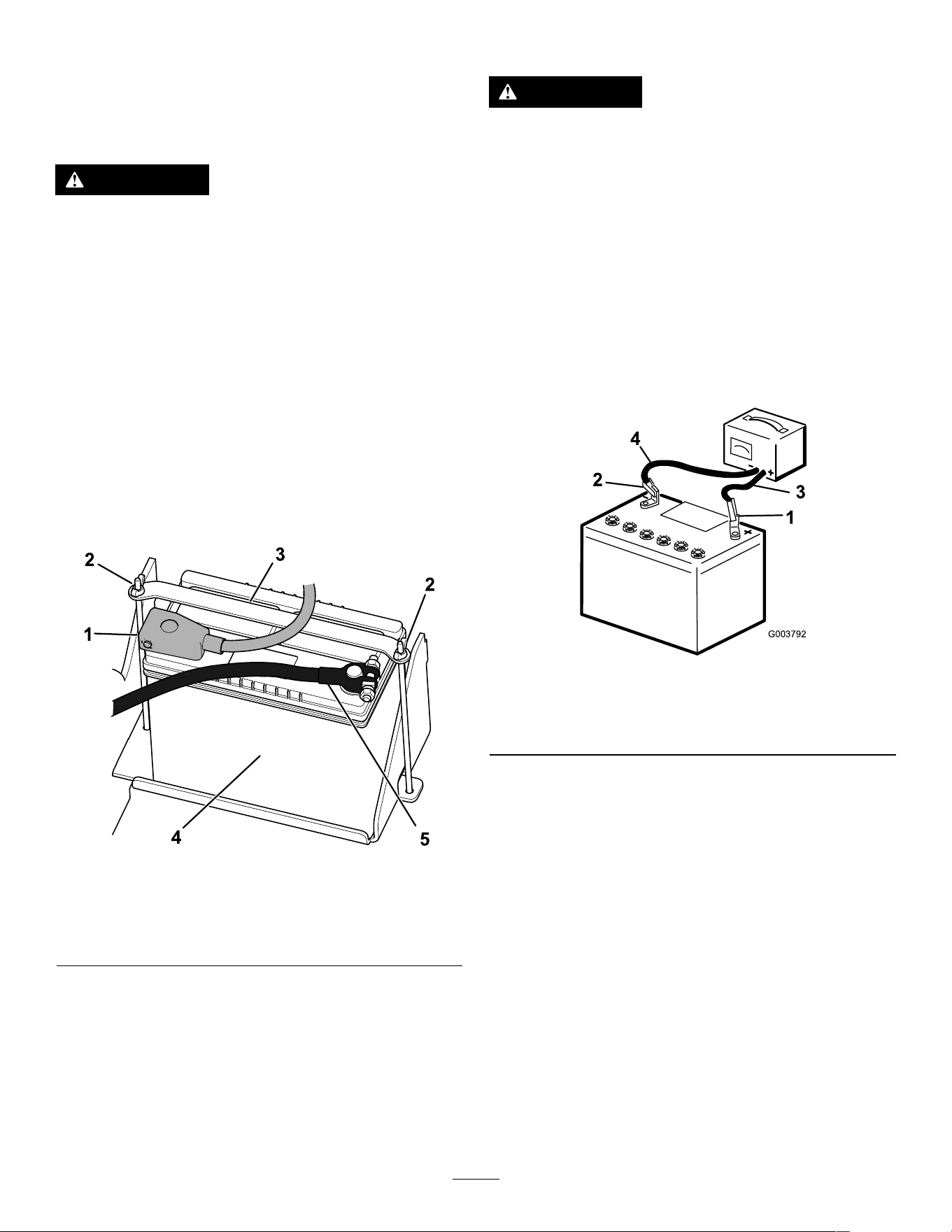
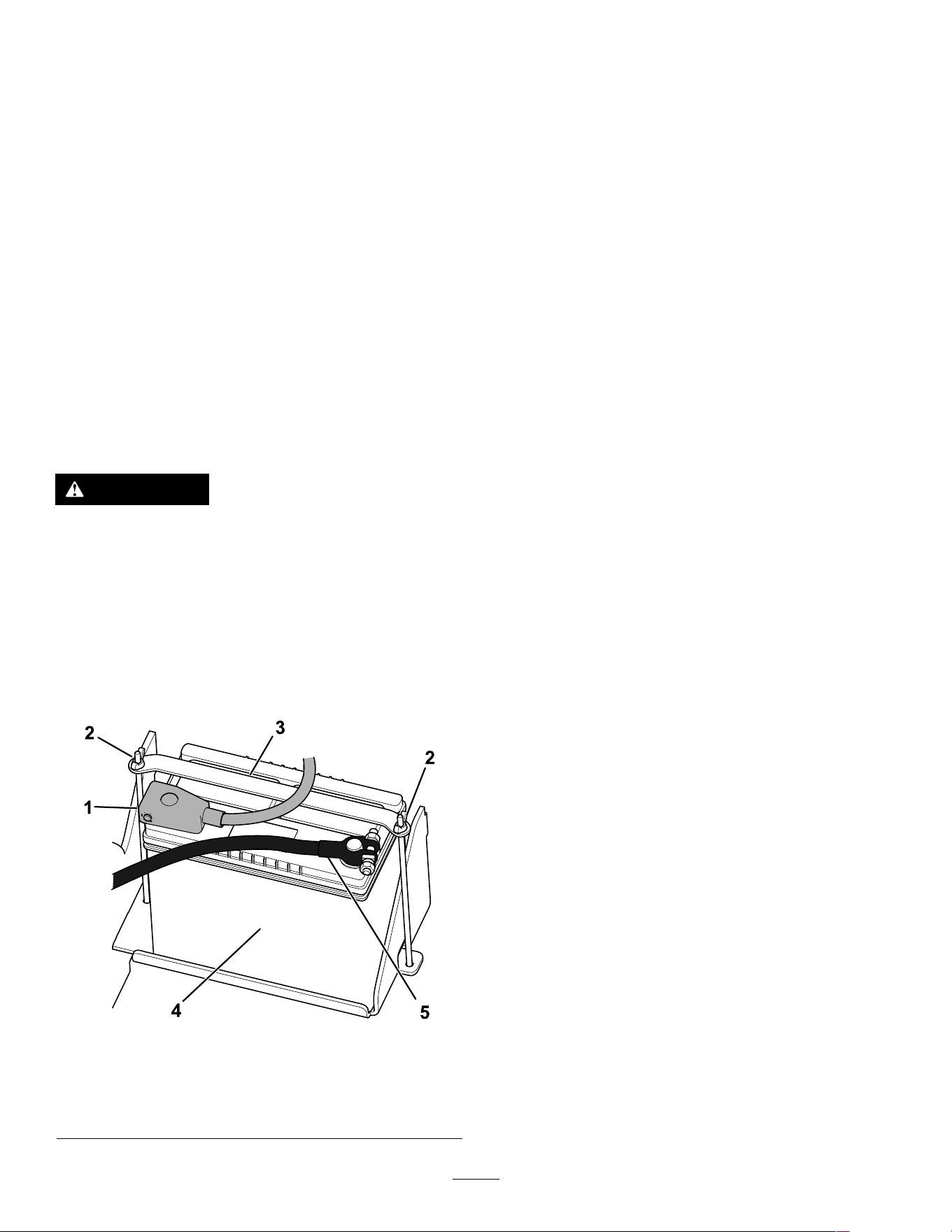
Servicing the Battery
Service Interval : Every 50 hours
Removing the Battery
W ARNING
Incorrect battery cable routing could damage
the machine and cables, causing sparks.
Sparks can cause the battery gasses to
explode, resulting in personal injury .
Always disconnect the negative (black)
battery cable before disconnecting the
positive (red) cable.
1. Park the machine on a level surface and engage
the parking brake.
2. Raise the loader arms and secure them with the
cylinder locks.
3. Shut of f the engine and remove the key .
4. Disconnect the negative (black) ground cable
from the battery post. Retain the fasteners.
g365667
Figure 50
1. Positive cable 4. Negative cable
2. Wing nut and rod (2)
5. Battery
3. Strap
5. Slide the rubber cover of f the positive (red)
cable.
6. Disconnect the positive (red) cable from the
battery post. Retain the fasteners.
7. Remove the wing nuts, rods, and strap.
8. Remove the battery .
Charging the Battery
W ARNING
Charging the battery produces gasses that
can explode.
Never smoke near the battery and keep sparks
and ames away from battery .
Important: Always keep the battery fully charged
(1.265 specic gravity). This is especially
important to prevent battery damage when the
temperature is below 0°C (32°F).
1. Remove the battery from the machine; refer to
Removing the Battery ( page 39 ) .
2. Charge the battery for 4 to 8 hours at a rate of 3
to 4 A. Do not overcharge the battery .
g003792
Figure 51
1. Positive battery post
3. Red (+) charger lead
2. Negative battery post
4. Black (-) charger lead
3. When the battery is fully charged, unplug
the charger from the electrical outlet, then
disconnect the charger leads from the battery
posts.
39
Cleaning the Battery
Note: Keep the terminals and the entire battery case
clean, to help extend battery life.
1. Park the machine on a level surface, engage
the parking brake (if equipped), and lower the
loader arms.
2. Shut of f the engine and remove the key .
3. Remove the battery from the machine;
Removing the Battery ( page 39 ) .
4. W ash the entire case with a solution of baking
soda and water .
5. Rinse the battery with clear water .
6. Coat the battery posts and cable connectors
with Grafo 1 12X (skin-over) grease or petroleum
jelly to prevent corrosion.
7. Install the battery; refer to Installing the Battery
( page 40 ) .
Installing the Battery
W ARNING
Incorrect battery cable routing could damage
the machine and cables, causing sparks.
Sparks can cause the battery gasses to
explode, resulting in personal injury .
Always connect the positive (red) battery
cable before connecting the negative (black)
cable.
1. Place the battery on the battery tray and secure
it with the strap, wing nuts, and rods.
g365667
Figure 52
1. Positive cable 4. Negative cable
2. Wing nut and rod (2)
5. Battery
3. Strap
2. Using the fasteners previously removed, install
the positive (red) battery cable to the positive
(+) battery terminal.
3. Slide the red terminal boot onto the positive
battery post.
4. Using the fasteners previously removed, install
the negative (black) battery cable to the negative
(-) battery terminal.
5. Close the hood.
Servicing a Replacement Battery
The original battery is maintenance-free and does not
require service. For servicing a replacement battery ,
refer to the battery manufacturer ’ s instructions.
40
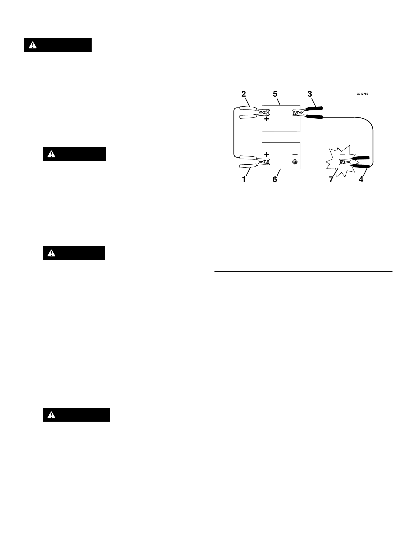
Jump-Starting the Machine
W ARNING
Jump-starting the battery can produce gasses
that can explode.
Do not smoke near the battery , and keep
sparks and ames away from battery .
1. Open the hood.
2. Check and clean corrosion from the battery
terminals before jump-starting. Ensure that the
connections are tight.
CAUTION
Corrosion or loose connections can
cause unwanted electrical voltage spikes
at any time during the jump-starting
procedure.
Do not attempt to jump-start the machine
with loose or corroded battery terminals,
or damage to the engine may occur .
DANGER
Jump-starting a weak battery that is
cracked or frozen or has a low electrolyte
level or an open/shorted battery cell can
cause an explosion, resulting in serious
personal injury .
Do not jump-start a weak battery if these
conditions exist.
3. Make sure that the booster battery is a good
and fully charged lead-acid battery at 12.6 V or
greater .
Note: Use properly sized jumper cables with
short lengths to reduce voltage drop between
systems. Make sure that the cables are color
coded or labeled for the correct polarity .
W ARNING
Batteries contain acid and produce
explosive gases.
• Shield your eyes and face from the
batteries at all times.
• Do not lean over the batteries.
Note: Ensure that the vent caps are tight and
level. Place a damp cloth, if available, over any
vent caps on both batteries. Also ensure that the
machines do not touch and that both electrical
systems are of f and at the same rated system
voltage. These instructions are for negative
ground systems only .
4. Connect the positive (+) cable to the positive (+)
terminal of the discharged battery that is wired
to the starter or solenoid as shown.
g012785
Figure 53
1. Positive (+) cable on
discharged battery
5. Booster battery
2. Positive (+) cable on
booster battery
6. Discharged battery
3. Negative (–) cable on the
booster battery
7. Engine block
4. Negative (–) cable on the
engine block
5. Connect the other end of the positive (+) jumper
cable to the positive terminal of the battery in
the other machine.
6. Connect an end of the negative (-) jumper cable
to the negative post of the battery in the other
machine.
7. Connect the other end of the negative (-) jumper
cable to a ground point, such as an unpainted
bolt or chassis member .
8. Start the engine in the other machine. Let it run
a few minutes, then start your engine.
9. Remove the cables in the reverse order of
connection.
10. Close the hood.
41
Servicing the Fuses
The electrical system is protected by fuses. It requires no maintenance; however , if a fuse blows, check
the component/circuit for a malfunction or a short.
g365804
Figure 54
Fuse Layout
1 2 3 4
5
6
7
8 9 10 1 1 12
A
B
(Relay) (Relay) (Relay) (Relay)
Key power
C
(20 A)
X
Hour meter
D
(10 A)
X
(Relay) (Relay) (Relay)
Power point/Light
kit
System power
Auxiliary power T elematics Accessory power
Start circuit
E
(15 A) (20 A)
(10 A) (10 A) (10 A) (15 A)
Note: If the machine does not start, either the main circuit or the control panel/relay fuse could be blown.
42
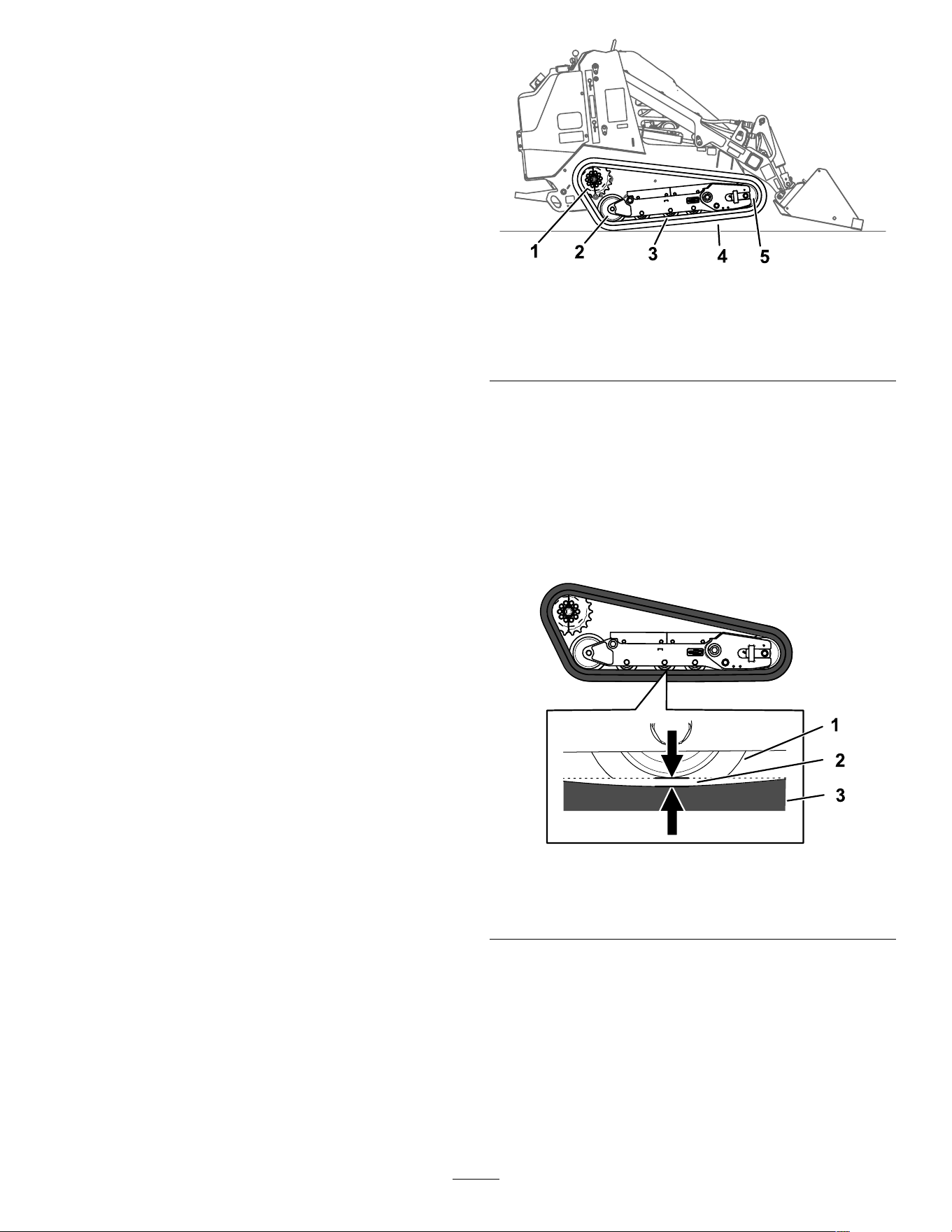
Drive System
Maintenance
Servicing the T racks
Service Interval : After the rst 8 hours —Check and
adjust the track tension.
After the rst 50 hours —Check and adjust the
track tension.
Every 50 hours —Check and adjust the track
tension.
Before each use or daily —Clean the tracks and
check for excessive wear and proper tension.
Cleaning the T racks
1. Park the machine on a level surface and engage
the parking brake.
2. With the bucket installed and angled downward,
lower it into the ground so that the front of the
traction unit lifts of f the ground a few centimeters
(inches).
3. Shut of f the engine and remove the key .
4. Using a water hose or pressure washer , remove
dirt from each track system.
Important: Ensure that you use high-pressure
water to wash only the track area. Do not use
a high-pressure washer to clean the rest of the
traction unit. Do not use high pressure water
between the drive sprocket and the traction unit or
you may damage the motor seals. High-pressure
washing can damage the electrical system and
hydraulic valves or deplete grease.
Important: Ensure that you fully clean the
road wheels, front wheel, rear wheel, and drive
sprocket. The road wheels should rotate freely
when clean.
g366284
Figure 55
1. Sectional drive sprocket
4. T rack
2. Rear wheel 5. Front wheel
3. Road wheel (4)
Checking and Adjusting the T rack
T ension
Lift/support 1 side of the machine and using the
weight of the track, verify that the gap between the
bottom of the lip of the road wheel and the track is
13 mm (1/2 inch). If it is not, adjust the track tension
using the following procedure.
g366296
Figure 56
1. Road wheel 3. T rack
2. 13 mm (1/2 inch) gap
1. Park the machine on a level surface, engage the
parking brake, and lower the loader arms.
2. Shut of f the engine and remove the key .
3. Raise the side of the machine that you are
adjusting so that the track is of f the ground.
43
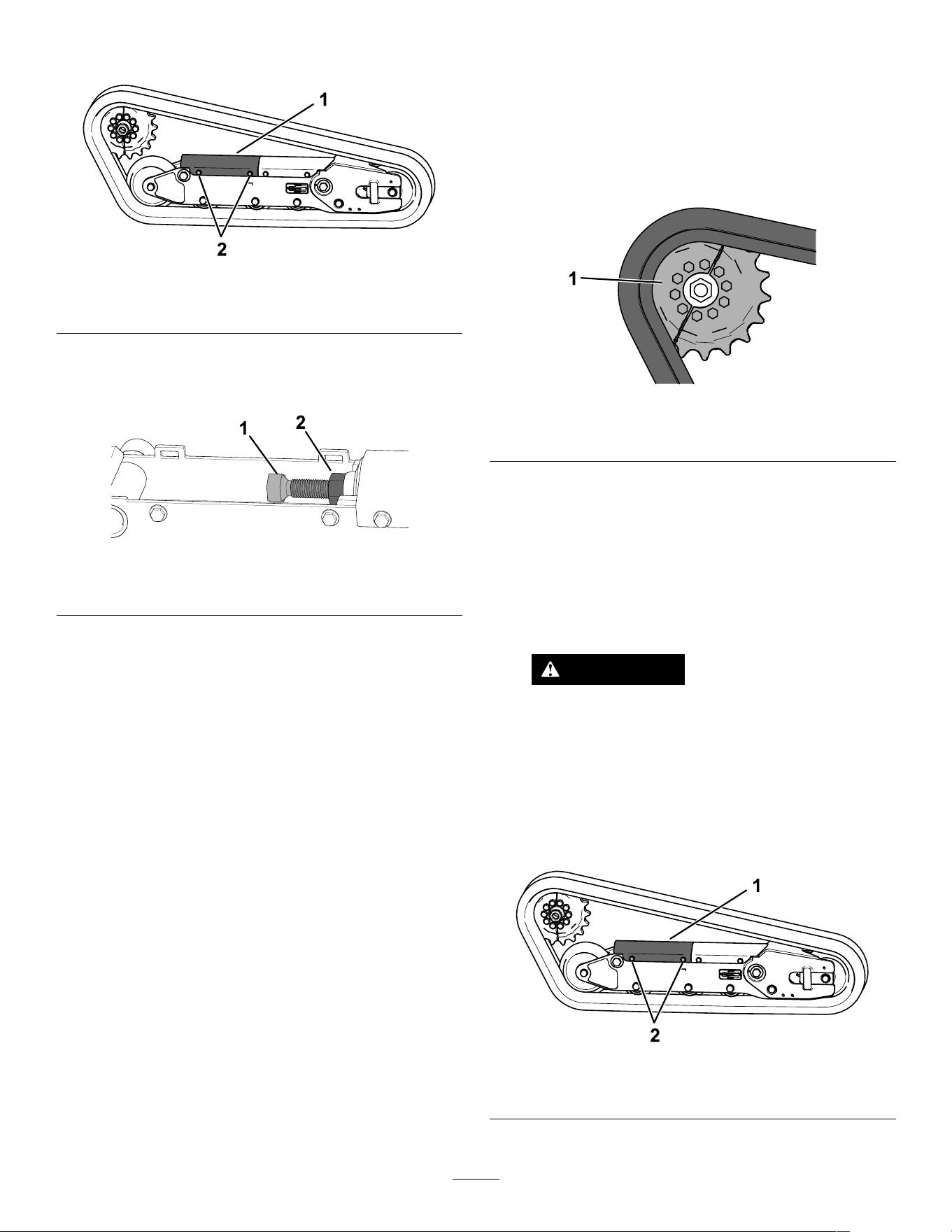
4. Loosen the bolts on the rear cover and remove
the cover .
g366295
Figure 57
1. Rear cover
2. Bolt (2)
5. Loosen the jam nut and adjust the tensioning
screw until the track deection is 13 mm (1/2
inch).
g363401
Figure 58
1. T ensioning screw 2. Jam nut
6. T ighten the jam nut.
7. Install the cover and tighten the bolts.
8. Repeat the procedure for the other track.
9. Drive the machine, then park the machine on a
level surface, engage the parking brake, shut of f
the engine, and remove the key .
10. V erify that the track deection is 13 mm (1/2
inch). Adjust if necessary .
Replacing the T racks
Removing the T racks
1. Remove any attachments.
2. Park the machine on a level surface, ensuring
that only 1 sprocket half is engaged with the
track.
g366389
Figure 59
1. Sprocket half
3. Lower the loader arms.
4. Shut of f the engine and remove the key .
5. Raise the machine of f the ground so that the
bottom of the track is at least 10.2 cm (4 inches)
of f the ground. Support the machine using jack
stands.
Note: Use jack stands rated for your machine.
W ARNING
Mechanical or hydraulic jacks may fail to
support the machine and cause serious
injury .
Use jack stands when supporting the
machine.
6. Loosen the bolts on the rear cover and remove
the cover .
g366295
Figure 60
1. Rear cover
2. Bolt (2)
44
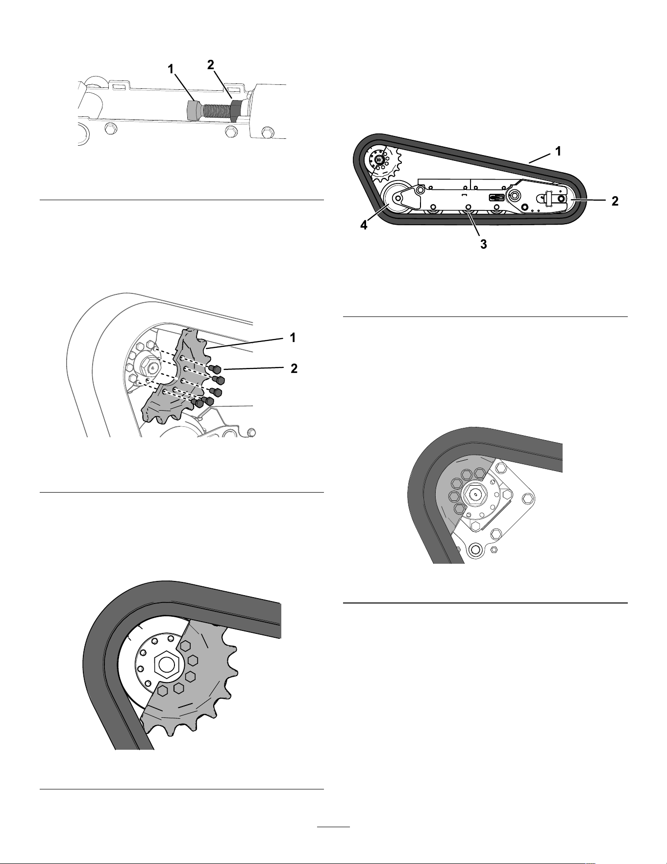
7. Loosen the jam nut and turn the tensioning
screw to release the tension.
g363401
Figure 61
1. T ensioning screw 2. Jam nut
8. Remove the segment of the drive sprocket not
engaged with the track.
Important: If you do not remove the
sprocket segment, it may be difcult to
install a new track without damaging it.
g366388
Figure 62
1. Bolt (5) 2. Sprocket half
9. Start the machine and disengage the parking
brake.
10. Move the traction control forward until the other
half of the drive sprocket is not engaged with
the track
g366387
Figure 63
1 1. Shut of f the engine and remove the key .
12. Remove the track from the track frame, drive
hub, then front wheel.
Installing the T racks
1. W rap the new track around the front wheel.
g366403
Figure 64
1. T rack
3. Road wheel (4)
2. Front wheel 4. Rear wheel
2. Push the track under and between the road
wheels and wrap it around the rear wheel.
3. Start the engine and disengage the parking
brake.
4. Move the traction control forward until the drive
sprocket half engages with the track.
g366402
Figure 65
5. Shut of f the engine and remove the key .
45
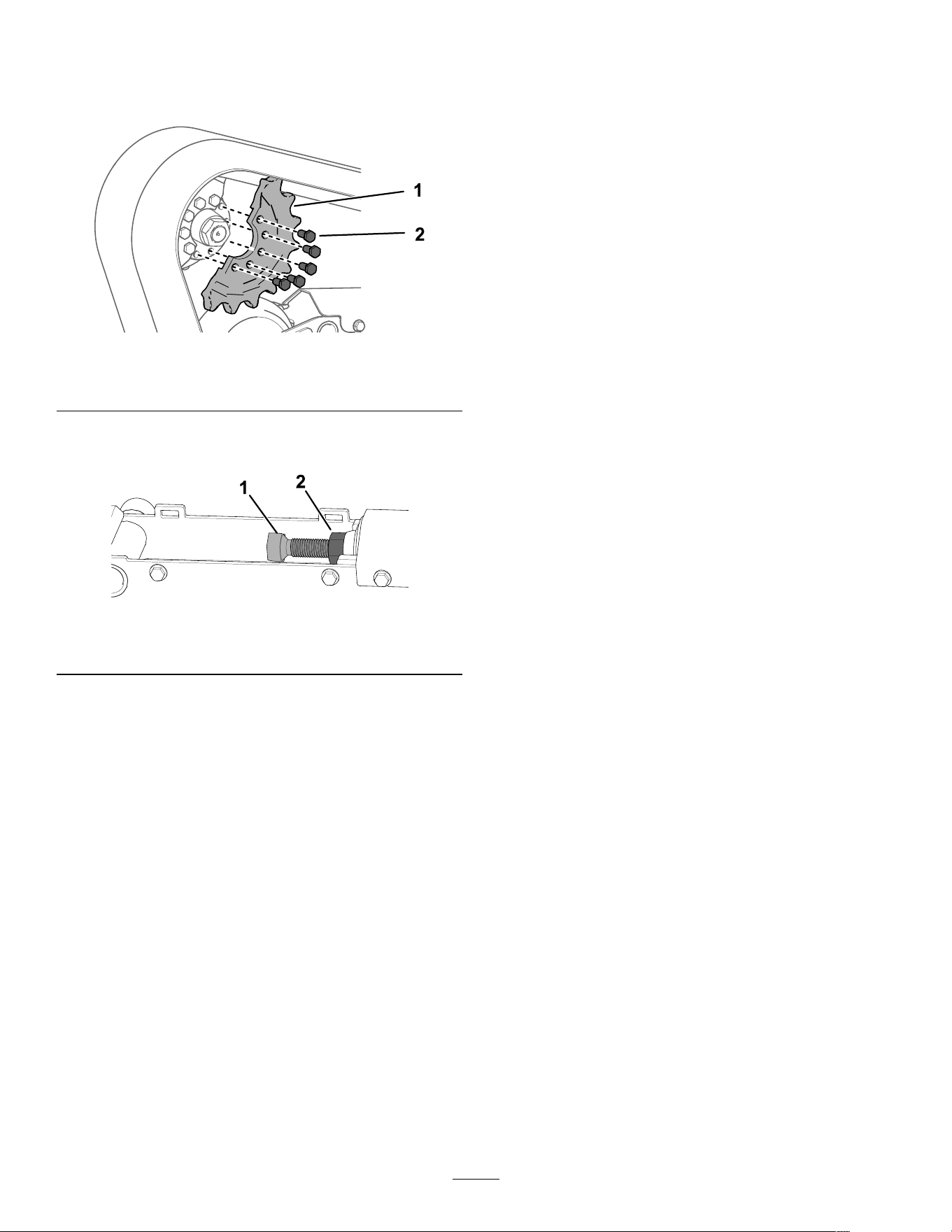
6. Apply thread-locking compound to the bolts of
the drive sprocket half that you removed and
install the other sprocket half. T orque the bolts
to 80 to 99 N∙m (59 to 73 ft-lb).
g366388
Figure 66
1. Bolt (5) 2. Sprocket half
7. Adjust the tensioning screw until the track
deection is 19 mm (3/4 inch).
g363401
Figure 67
1. T ensioning screw 2. Jam nut
8. T ighten the jam nut.
9. Install the cover and tighten the bolts.
10. Repeat the procedure to replace the other track.
1 1. Lower the machine to the ground.
12. Drive the machine, then park the machine on a
level surface, engage the parking brake, shut of f
the engine, and remove the key .
13. V erify that the track tension is correct; refer to
Checking and Adjusting the T rack T ension ( page
43 ) .
Cooling System
Maintenance
Cooling System Safety
• Swallowing engine coolant can cause poisoning;
keep out of reach from children and pets.
• Discharge of hot, pressurized coolant or touching
a hot radiator and surrounding parts can cause
severe burns.
– Always allow the engine to cool at least 15
minutes before removing the radiator cap.
– Use a rag when opening the radiator cap, and
open the cap slowly to allow steam to escape.
Servicing the Cooling
System
Service Interval : Before each use or daily —Clean
the screen, oil cooler , and front of
the radiator (more often in dirty or
dusty conditions).
Every 100 hours —Check the cooling system
hoses.
Cleaning the Radiator Screen
Service Interval : Before each use or daily
Remove any buildup of grass, dirt or other debris from
the radiator screen with compressed air .
46
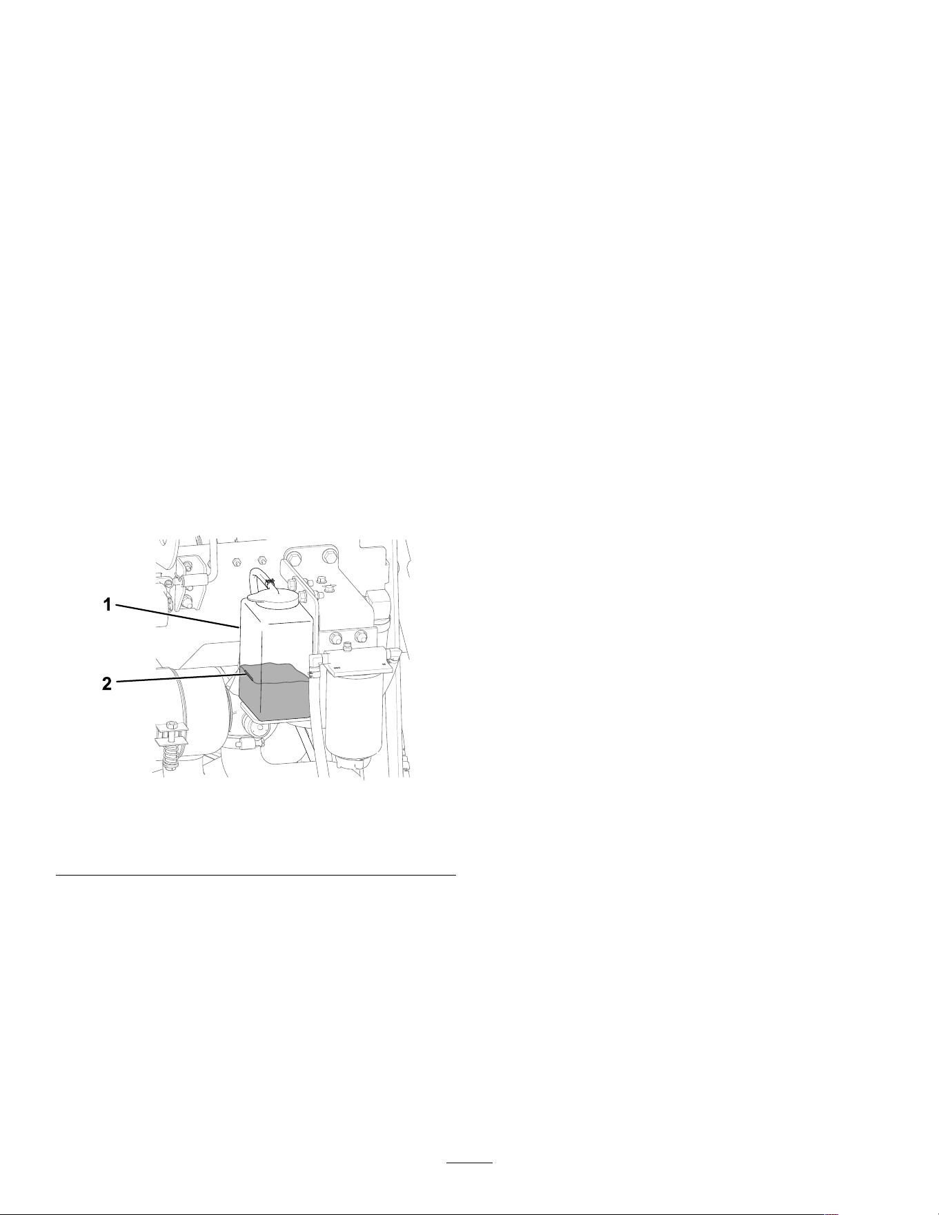
Checking the Engine-Coolant
Level
Service Interval : Before each use or daily —Check
the coolant level in the expansion
tank.
Capacity: 5 L (5.2 US qts)
T ype: 50/50 solution of water and permanent
ethylene-glycol antifreeze.
1. Park the machine on a level surface, engage the
parking brake, and lower the loader arms.
2. Open the hood and secure the prop rod.
Note: Y ou cannot open the hood after raising
the loader arms.
3. Raise the loader arms and secure them with the
cylinder locks.
4. Shut of f the engine, remove the key , and allow
the engine to cool.
5. Check the coolant level in the expansion tank.
Note: The coolant level should be at or above
the mark on the side of the tank.
g366894
Figure 68
1. Expansion tank
2. Full mark
6. If the coolant level is low , remove the expansion
tank cap and add a 50/50 mixture of water and
permanent ethylene-glycol antifreeze.
Important: Do not overll the expansion
tank.
7. Install the expansion-tank cap.
8. Remove the cylinder locks and lower the loader
arms.
9. Close the hood.
Changing the Engine Coolant
Service Interval : Every 500 hours
Have an Authorized Service Dealer change the engine
coolant yearly .
If you need to add engine coolant, refer to Checking
the Engine-Coolant Level ( page 47 ) .
47
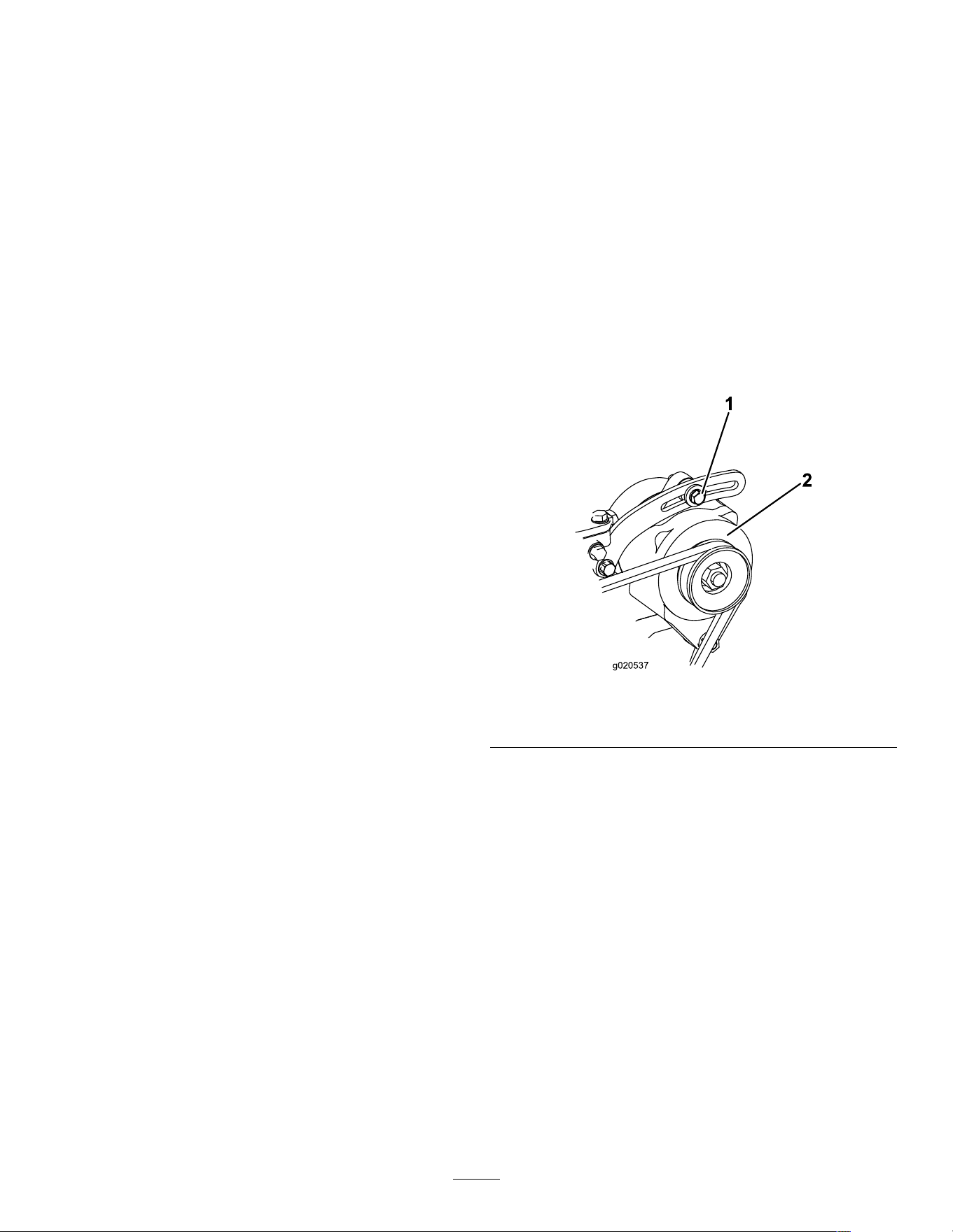
Brake Maintenance
T esting the Parking Brake
Service Interval : Before each use or daily
1. Engage the parking-brake; refer to
Parking-Brake Lever ( page 14 ) .
2. Start the engine.
3. Slowly attempt to drive the machine forward or
rearward.
4. If the machine moves, contact your Authorized
Service Dealer for service.
Belt Maintenance
Checking the
Alternator-Belt T ension
Service Interval : Before each use or daily
Every 500 hours (Refer to the engine owner ’ s
manual for instructions.)
Proper tension of the belt allows 10 mm (3/8 inch) of
deection when a force of 10 kg (22 lb) is applied on
the belt midway between the pulleys.
If the deection is not 10 mm (3/8 inch), perform the
following steps:
1. Loosen the alternator-mounting bolt.
g020537
Figure 69
1. Mounting bolt 2. Alternator
2. Increase or decrease the alternator-belt tension
and tighten the bolt.
3. Check the deection of the belt again to ensure
that the tension is correct.
48
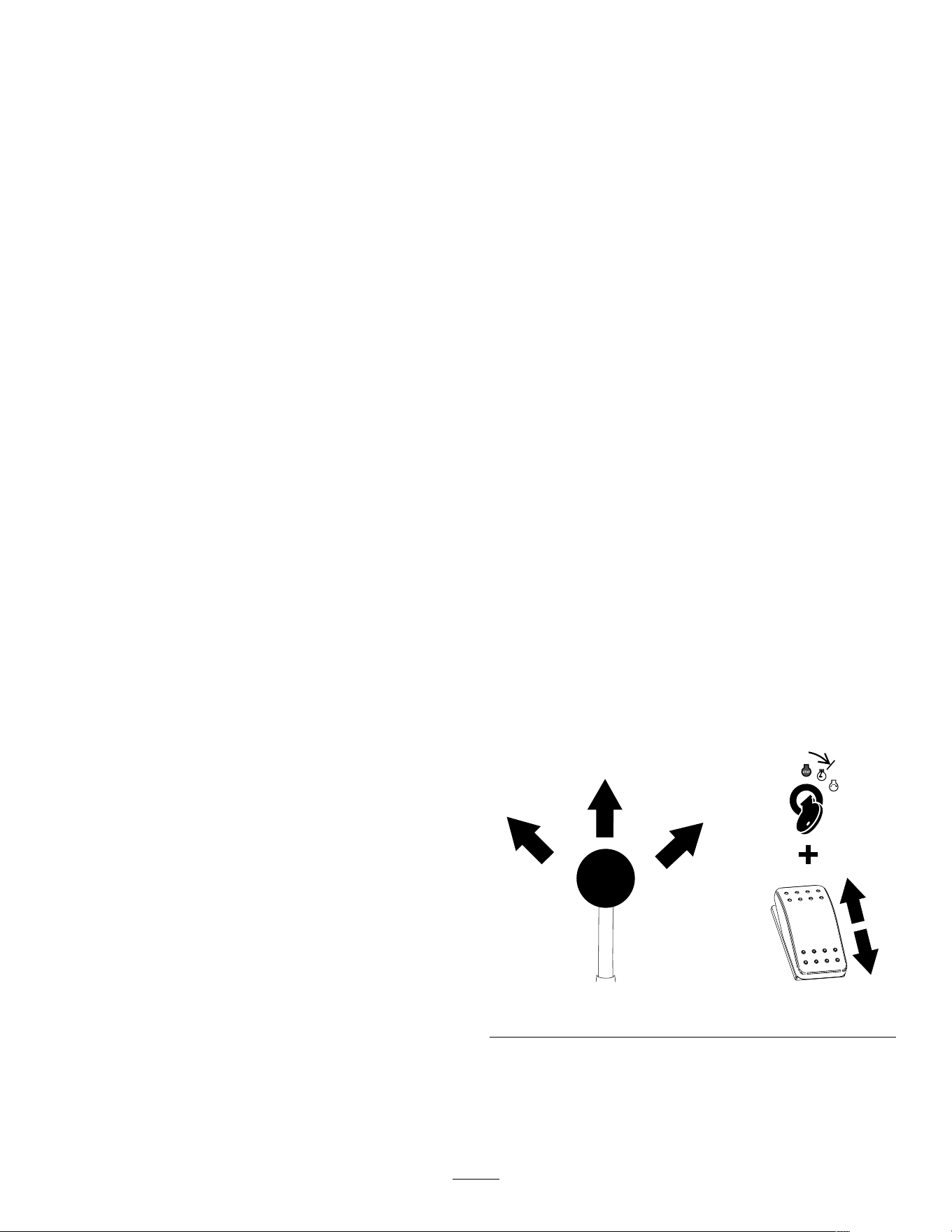
Controls System
Maintenance
Adjusting the Controls
The factory adjusts the controls before shipping the
machine. However , after many hours of use, you
may need to adjust the traction control alignment,
the N EUTRAL position of the traction control, and the
tracking of the traction control in the full forward
position.
Contact your Authorized Service Dealer to adjust the
controls of your machine.
Hydraulic System
Maintenance
Hydraulic System Safety
• Seek immediate medical attention if uid is injected
into skin. Injected uid must be surgically removed
within a few hours by a doctor .
• Ensure that all hydraulic-uid hoses and lines are
in good condition and all hydraulic connections
and ttings are tight before applying pressure to
the hydraulic system.
• Keep your body and hands away from pinhole
leaks or nozzles that eject high-pressure hydraulic
uid.
• Use cardboard or paper to nd hydraulic leaks.
• Safely relieve all pressure in the hydraulic system
before performing any work on the hydraulic
system.
Relieving Hydraulic
Pressure
T o relieve hydraulic pressure while the engine is on,
disengage the auxiliary hydraulics and fully lower and
retract the loader arms.
T o relieve the pressure while the engine is of f, cycle
the loader-arm/attachment-tilt lever between the
forward positions to lower the loader arms. T urn
the key switch to the R UN position and press the
auxiliary-hydraulic switch back and forth.
g509956
Figure 70
49
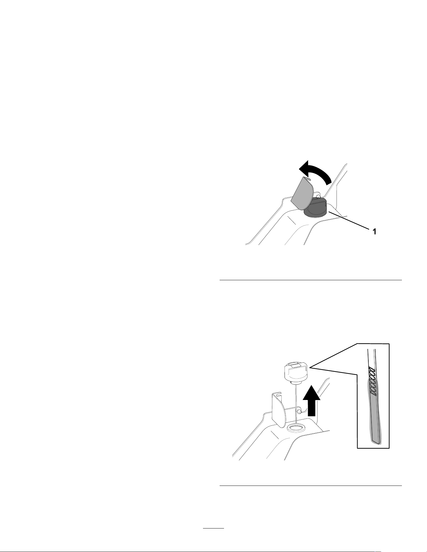
Hydraulic Fluid
Specications
Hydraulic-System Capacity: 37.8 L (10 US gallons)
Recommended hydraulic uid: T oro PX Extended
Life Hydraulic Fluid
Note: A machine using the recommended
replacement uid requires less frequent uid and lter
changes.
Alternative hydraulic uids: If T oro PX Extended
Life Hydraulic Fluid is not available, you may use
another conventional, petroleum-based hydraulic uid
having specications that fall within the listed range
for all the following material properties and that it
meets industry standards. Do not use synthetic uid.
Consult with your lubricant distributor to identify a
satisfactory product.
Note: T oro does not assume responsibility for
damage caused by improper substitutions, so use
products only from reputable manufacturers who will
stand behind their recommendation.
High V iscosity Index/Low Pour Point
Anti-wear Hydraulic Fluid, ISO VG 46
Material Properties:
V iscosity , ASTM D445 cSt @ 40°C (104°F)
44 to 48
V iscosity Index ASTM D2270
140 or higher
Pour Point, ASTM D97 -37°C to -45°C (-34°F
to -49°F)
Industry Specications: Eaton V ickers 694 (I-286-S,
M-2950-S/35VQ25 or
M-2952-S)
Note: Many hydraulic uids are almost colorless,
making it dif cult to spot leaks. A red dye additive for
the hydraulic uid is available in 20 ml (0.67 oz)
bottles. A bottle is suf cient for 15 to 22 L (4 to 6 US
gallons) of hydraulic uid. Order Part No. 44-2500
from your Authorized Service Dealer .
Checking the
Hydraulic-Fluid Level
Service Interval : Every 25 hours
Important: Always use the correct hydraulic
uid. Unspecied uids will damage the hydraulic
system. Refer to Hydraulic Fluid Specications
( page 50 ) .
1. Remove any attachments.
2. Park the machine on a level surface and engage
the parking brake.
3. Shut of f the engine and remove the key .
4. Raise the bracket.
g366993
Figure 71
1. Filler cap
5. Clean the area around the ller cap .
6. Remove the ller-neck cap and check the uid
level on the dipstick.
Note: The uid level should be within the marks
on the dipstick.
g366992
Figure 72
50
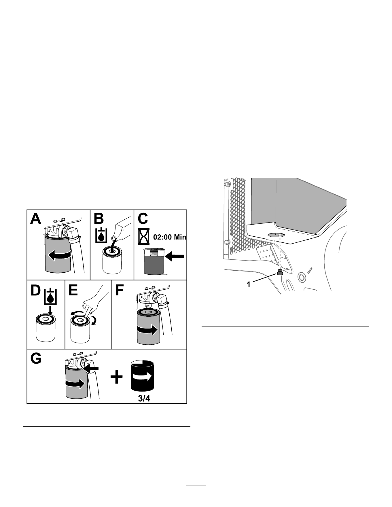
7. If the level is low , add enough uid to raise it to
the proper level.
8. Install the ller cap.
9. Lower the bracket.
Replacing the Hydraulic
Filter
Service Interval : After the rst 8 hours
Every 250 hours
Important: Do not substitute an automotive oil
lter; otherwise, severe hydraulic system damage
may result.
1. Park the machine on a level surface, engage the
parking brake, and lower the loader arms.
2. Shut of f the engine and remove the key .
3. Open the hood and secure the prop rod.
4. Place a drain pan under the lter and replace
the lter as shown.
g367095
Figure 73
5. Clean up any spilled uid.
6. Start the engine and let it run for about 2 minutes
to purge air from the system.
7. Shut of f the engine and check for leaks.
8. Check the uid level in the hydraulic tank; refer
to Hydraulic Fluid Specications ( page 50 ) and
add uid to raise the level to mark on dipstick.
Important: Do not overll the tank.
9. Close the hood.
Changing the Hydraulic
Fluid
Service Interval : Every 500 hours
1. Park the machine on a level surface, engage the
parking brake, and lower the loader arms.
2. Shut of f the engine and remove the key .
3. Place a large drain pain capable of holding 57
L (15 US gallons) under the drain plug on the
hydraulic tank.
g367140
Figure 74
1. Drain plug
4. Remove the drain plug and allow the oil to drain
into the pan.
5. When the oil is nished draining, install and
tighten the drain plug.
Note: Dispose of the used oil at a certied
recycling center .
6. Fill the hydraulic tank with hydraulic uid; refer
to Hydraulic Fluid Specications ( page 50 ) .
7. Start the engine and let it run for a few minutes.
8. Shut of f the engine and remove the key .
9. Check the hydraulic-uid level and add uid to
ll the tank if necessary; refer to Checking the
Hydraulic-Fluid Level ( page 50 ) .
51
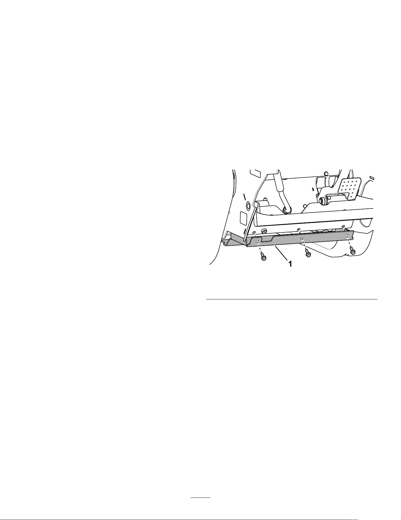
Cleaning
Removing Debris
Service Interval : Before each use or daily
Important: Operating the engine with blocked
screens and/or cooling shrouds removed will
result in engine damage from overheating.
1. Park the machine on a level surface and lower
the loader arms.
2. Shut of f the engine, remove the key , and allow
the engine to cool.
3. Open the hood and secure the prop rod.
4. Wipe away debris from the air cleaner .
5. Clean any debris buildup on the engine and in
the oil cooler ns with a brush or blower .
Important: Operating the engine with
blocked screens and/or cooling shrouds
removed will result in engine damage due to
overheating.
6. Clean debris from the hood opening, muf er ,
heat shields, and radiator screen (if applicable).
7. Close the hood.
W ashing the Machine
When pressure washing the machine, do the following:
• W ear appropriate personal protective equipment
for the pressure washer .
• Keep all guards in place on the machine.
• A void spraying at electronic components.
• A void spraying at edges of decals.
• Spray the exterior of the machine only . Do not
spray directly into openings in the machine.
• Spray only the dirty parts of the machine.
• Use a 40-degree or larger spray nozzle. 40-degree
nozzles are usually white.
• Keep the tip of the pressure washer at least 61 cm
(2 ft) away from the surface being washed.
• Use only pressure washers with pressure below
13790 kpa (2000 psi) and ow below 7.6 L (2 US
gallons) per minute.
• Replace damaged or peeling decals.
• Grease all grease points after washing; refer to
Greasing the Machine ( page 32 ) .
Cleaning the Chassis
Service Interval : Every 100 hours —Check for dirt
buildup in the chassis.
Over time, the chassis under the engine collects dirt
and debris that must be removed. Open the hood,
secure the prop rod, and use a ashlight to inspect the
area under the engine regularly . When the debris is
2.5 to 5 cm (1 to 2 inches) deep, clean the chassis.
1. Park the machine on a level surface, engage the
parking brake, and lower the loader arms.
2. Raise the front of the machine so that the
machine is angled backward.
3. Shut of f the engine and remove the key .
4. Remove the 2 bolts securing the bottom plate
and remove the bottom plate.
g367142
Figure 75
1. Bottom plate
5. Remove the front cover; refer to Removing the
Front Cover ( page 31 ) .
6. Spray water into the chassis to clean out the dirt
and debris.
Note: The water will drain at the back of the
machine.
Important: Do not spray water into the
engine.
7. Grease the machine; refer to Greasing the
Machine ( page 32 ) .
8. Install the bottom plate.
9. Install the front screen.
10. Lower the machine.
52

Storage
Storage Safety
• Shut of f the engine, remove the key , wait for all
moving parts to stop, and allow the machine to
cool before storing it.
• Do not store the machine or fuel near ames.
Storage
1. Park the machine on a level surface, engage the
parking brake, and lower the loader arms.
2. Shut of f the engine and remove the key .
3. Remove dirt and grime from the entire machine.
Important: Y ou can wash the machine
with mild detergent and water . Do not
pressure-wash the machine. A void
excessive use of water , especially near the
control panel, engine, hydraulic pumps, and
motors.
4. Service the air cleaner; refer to Servicing the
Air-Cleaner ( page 32 ) .
5. Grease the machine; refer to Greasing the
Machine ( page 32 ) .
6. Change the engine oil; refer to Changing the
Engine Oil and Filter ( page 35 ) .
7. Charge the battery; refer to Charging the Battery
( page 39 ) .
8. Check and adjust the track tension; refer to
Checking and Adjusting the T rack T ension ( page
43 ) .
9. Check and tighten all fasteners. Repair or
replace any worn, damaged, or missing parts.
10. Paint all scratched or bare metal surfaces with
paint available from your Authorized Service
Dealer .
1 1. Store the machine in a clean, dry garage or
storage area. Remove the key from the ignition
switch and keep it in a memorable place.
12. Disconnect the battery; refer to Using the
Battery-Disconnect Switch ( page 38 ) .
13. Cover the machine to protect it and keep it clean.
53

T roubleshooting
Problem
Possible Cause Corrective Action
1. The electrical connections are
corroded or loose.
1. Check the electrical connections for
good contact.
2. A fuse is blown or loose. 2. Correct or replace the fuse.
3. The battery is discharged.
3. Charge the battery or replace it.
4. The relay or switch is damaged.
4. Contact your Authorized Service
Dealer .
5. A starter or starter solenoid is
damaged.
5. Contact your Authorized Service
Dealer .
6. Internal engine components have
seized.
6. Contact your Authorized Service
Dealer .
The starter does not crank.
7. The safety interlock is engaged. 7. Check the neutral setting on the
traction and auxiliary controls.
1. The starting procedure is incorrect.
1. Refer to Starting the Engine.
2. The fuel tank is empty . 2. Fill the tank with fresh fuel.
3. The fuel-shutof f valve is closed. 3. Open the fuel-shutof f valve.
4. Dirt, water , stale fuel, or incorrect fuel
is in the fuel system.
4. Drain and ush the fuel system; add
fresh fuel.
5. The fuel line is clogged. 5. Clean or replace the fuel line.
6. There is air in the fuel. 6. Bleed the nozzles and check for air
leaks at the fuel hose connections
and ttings between the fuel tank and
engine.
7. The glow plugs are inoperative.
7. Check the fuse, glow plugs, and wiring.
8. The cranking speed is slow .
8. Check the battery , oil viscosity , and
starting motor (contact your Authorized
Service Dealer).
9. The air-cleaner lters are dirty . 9. Service the air lters.
10. The fuel lter is clogged. 10. Replace the fuel lter .
1 1. The improper fuel grade for cold
weather is in the machine.
1 1. Drain the fuel system and replace
the fuel lter . Add fresh fuel of
proper grade for ambient temperature
conditions. Y ou may need to warm the
entire traction unit.
12. There is low compression.
12. Contact your Authorized Service
Dealer .
13. The injection nozzles are damaged.
13. Contact your Authorized Service
Dealer .
14. The injection pump timing is incorrect.
14. Contact your Authorized Service
Dealer .
15. The injection pump is damaged.
15. Contact your Authorized Service
Dealer .
The engine cranks but does not start.
16. The ETR solenoid is damaged.
16. Contact your Authorized Service
Dealer .
54

Problem
Possible Cause Corrective Action
1. The fuel-tank vent is restricted. 1. Loosen the cap. If the engine runs with
the cap loosened, replace the cap.
2. Dirt or water is in the fuel system. 2. Drain and ush the fuel system; add
fresh fuel.
3. The fuel lter is clogged. 3. Replace the fuel lter .
4. There is air in the fuel. 4. Bleed the nozzles and check for air
leaks at fuel hose connections and
ttings between the fuel tank and
engine.
5. Improper fuel grade for cold weather
was used in the machine.
5. Drain the fuel system and replace
the fuel lter . Add fresh fuel of
proper grade for ambient temperature
conditions.
6. The spark-arrestor screen is clogged.
6. Clean or replace the spark-arrestor
screen.
The engine starts but does not keep
running.
7. The fuel pump is damaged. 7. Contact your Authorized Service
Dealer .
1. Dirt, water , stale fuel, or incorrect fuel
is in the fuel system.
1. Drain and ush the fuel system; add
fresh fuel.
2. The engine is overheating.
2. Refer to “The engine overheats.”
3. There is air in the fuel. 3. Bleed the nozzles and check for air
leaks at the fuel hose connections
and ttings between the fuel tank and
engine.
4. The injection nozzles are damaged.
4. Contact your Authorized Service
Dealer .
5. There is low compression
5. Contact your Authorized Service
Dealer .
6. The injection-pump timing is incorrect.
6. Contact your Authorized Service
Dealer .
7. There is excessive carbon buildup.
7. Contact your Authorized Service
Dealer .
The engine runs but knocks or misses.
8. There is internal wear or damage.
8. Contact your Authorized Service
Dealer .
1. The fuel-tank vent is restricted. 1. Loosen the cap. If the engine runs with
the cap loosened, replace the cap.
2. Dirt, water , stale fuel, or incorrect fuel
is in the fuel system.
2. Drain and ush the fuel system; add
fresh fuel.
3. The air-cleaner lters are dirty . 3. Service the air lters.
4. The fuel lter is clogged. 4. Replace the fuel lter .
5. There is air in the fuel. 5. Bleed the nozzles and check for air
leaks at fuel hose connections and
ttings between the fuel tank and
engine.
6. The fuel pump is damaged. 6. Contact your Authorized Service
Dealer .
The engine does not idle.
7. There is low compression
7. Contact your Authorized Service
Dealer .
55

Problem
Possible Cause Corrective Action
1. More coolant is needed.
1. Check and add coolant.
2. There is restricted air ow to the
radiator .
2. Inspect and clean the radiator screen
with every use.
3. The crankcase-oil level is incorrect. 3. Fill or drain to the Full mark.
4. The engine load is excessive. 4. Reduce the load; use a lower ground
speed.
5. Incorrect fuel is in the fuel system. 5. Drain and ush the fuel system; add
fresh fuel.
6. The thermostat is damaged.
6. Contact your Authorized Service
Dealer .
7. The fan belt is loose or broken. 7. Contact your Authorized Service
Dealer .
8. Injection timing is incorrect.
8. Contact your Authorized Service
Dealer .
9. The coolant pump is damaged.
9. Contact your Authorized Service
Dealer .
The engine overheats.
10. The engine rpm is too low .
10. Check the high idle speed.
1. The engine load is excessive. 1. Reduce the load; use a lower ground
speed.
2. The crankcase-oil level is incorrect. 2. Fill or drain to the Full mark.
3. The air-cleaner lters are dirty . 3. Service the air lters.
4. Dirt, water , stale fuel, or incorrect fuel
is in the fuel system.
4. Drain and ush the fuel system; add
fresh fuel.
5. The engine is overheating.
5. Refer to “The engine overheats.”
6. The spark-arrestor screen is clogged.
6. Clean or replace the spark-arrestor
screen.
7. There is air in the fuel. 7. Bleed the nozzles and check for air
leaks at fuel hose connections and
ttings between the fuel tank and
engine.
8. There is low compression
8. Contact your Authorized Service
Dealer .
9. The fuel-tank vent is restricted.
9. Contact your Authorized Service
Dealer .
10. The injection-pump timing is incorrect.
10. Contact your Authorized Service
Dealer .
1 1. The injection pump is damaged.
1 1. Contact your Authorized Service
Dealer .
The engine loses power .
12. The engine high idle speed is too low .
12. Contact your Authorized Service
Dealer .
1. The engine load is excessive. 1. Reduce the load; use a lower ground
speed.
2. The air-cleaner lters are dirty . 2. Service the air lters.
3. Incorrect fuel is in the fuel system. 3. Drain and ush the fuel system; add
fresh fuel.
4. The injection-pump timing is incorrect.
4. Contact your Authorized Service
Dealer .
5. The injection pump is damaged.
5. Contact your Authorized Service
Dealer .
Exhaust produces excessive black smoke.
6. The injection nozzles are damaged.
6. Contact your Authorized Service
Dealer .
56

Problem
Possible Cause Corrective Action
1. The key was turned to the S TART
position before the glow-plug light
turned of f.
1. T urn the key to the R UN position and
allow the glow-plug light to turn of f
before starting the engine.
2. The engine temperature is low .
2. Check the thermostat.
3. The glow plugs are inoperative.
3. Check the fuse, glow plugs, and wiring.
4. The injection-pump timing is incorrect.
4. Contact your Authorized Service
Dealer .
5. The injection nozzles are damaged.
5. Contact your Authorized Service
Dealer .
Exhaust produces excessive white smoke.
6. There is low compression.
6. Contact your Authorized Service
Dealer .
1. The traction-control hydraulics are
disabled.
1. T oggle the traction-enable switch.
2. The parking brake is engaged. 2. Disengage the parking brake.
3. The hydraulic-uid level is low . 3. Add hydraulic uid to the reservoir .
4. The hydraulic system is damaged.
4. Contact your Authorized Service
Dealer .
5. The tow valves are open.
5. Close the tow valves.
6. The ow-divider valve lever is in 9
o'clock position.
6. Move the lever to the 12 o'clock to 10
o'clock position.
7. A traction pump drive coupler is loose
or broken.
7. Contact your Authorized Service
Dealer .
8. Pump and/or wheel motor is damaged. 8. Contact your Authorized Service
Dealer .
9. The control valve is damaged.
9. Contact your Authorized Service
Dealer .
The machine does not drive.
10. The relief valve is damaged. 10. Contact your Authorized Service
Dealer .
57

Notes:

California Proposition 65 W arning Information
What is this warning?
Y ou may see a product for sale that has a warning label like the following:
W ARNING: Cancer and Reproductive Harm—www .p65W arnings.ca.gov .
What is Prop 65?
Prop 65 applies to any company operating in California, selling products in California, or manufacturing products that may be sold in or brought into
California. It mandates that the Governor of California maintain and publish a list of chemicals known to cause cancer , birth defects, and/or other
reproductive harm. The list, which is updated annually , includes hundreds of chemicals found in many everyday items. The purpose of Prop 65 is to
inform the public about exposure to these chemicals.
Prop 65 does not ban the sale of products containing these chemicals but instead requires warnings on any product, product packaging, or literature with
the product. Moreover , a Prop 65 warning does not mean that a product is in violation of any product safety standards or requirements. In fact, the
California government has claried that a Prop 65 warning “is not the same as a regulatory decision that a product is ‘safe’ or ‘unsafe.’” Many of these
chemicals have been used in everyday products for years without documented harm. For more information, go to https://oag.ca.gov/prop65/faqs-view-all .
A Prop 65 warning means that a company has either (1) evaluated the exposure and has concluded that it exceeds the “no signicant risk level”; or (2)
has chosen to provide a warning based on its understanding about the presence of a listed chemical without attempting to evaluate the exposure.
Does this law apply everywhere?
Prop 65 warnings are required under California law only . These warnings are seen throughout California in a wide range of settings, including but not
limited to restaurants, grocery stores, hotels, schools, and hospitals, and on a wide variety of products. Additionally , some online and mail order
retailers provide Prop 65 warnings on their websites or in catalogs.
How do the California warnings compare to federal limits?
Prop 65 standards are often more stringent than federal and international standards. There are various substances that require a Prop 65 warning
at levels that are far lower than federal action limits. For example, the Prop 65 standard for warnings for lead is 0.5 μg/day , which is well below
the federal and international standards.
Why don’t all similar products carry the warning?
• Products sold in California require Prop 65 labelling while similar products sold elsewhere do not.
• A company involved in a Prop 65 lawsuit reaching a settlement may be required to use Prop 65 warnings for its products, but other companies
making similar products may have no such requirement.
• The enforcement of Prop 65 is inconsistent.
• Companies may elect not to provide warnings because they conclude that they are not required to do so under Prop 65; a lack of warnings for a
product does not mean that the product is free of listed chemicals at similar levels.
Why does T oro include this warning?
T oro has chosen to provide consumers with as much information as possible so that they can make informed decisions about the products they buy and
use. T oro provides warnings in certain cases based on its knowledge of the presence of one or more listed chemicals without evaluating the level of
exposure, as not all the listed chemicals provide exposure limit requirements. While the exposure from T oro products may be negligible or well within the
“no signicant risk” range, out of an abundance of caution, T oro has elected to provide the Prop 65 warnings. Moreover , if T oro does not provide these
warnings, it could be sued by the State of California or by private parties seeking to enforce Prop 65 and subject to substantial penalties.
Rev A