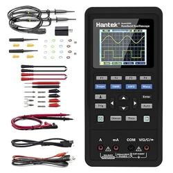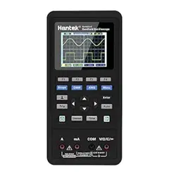
User’s Manual For MT8206
◆ Multimeter with 200K A/D sampling and 4000 counts auto-range
◆ One-button switch to graphical waveform display during measurement
◆ Reliable panel calibration technology , memory calibration coefficients
◆ Displaying historical data and real-time measurement on the same screen
◆ Featuring DC/AC voltage/current, resistance, capacitance/mF
Frequency/duty cycle, diode/continuity tes

Introduction
Dear users,
Thank you for purchasing the MT8206 Digital Graphical Multimeter. The digital graphical multimeter capable
of displaying the waveform is inevitable in the development of the measuring instrument from analog (pointer). I
believe that the innovative function combination and user-friendly design of MT8206 Digital Graphical Multimeter
will be of great help to your on-site inspection. Please read the this manual carefully before use, especially the
“Safety Instruction”. Keep this manual properly after reading it for future reference.
Intellectual property
This product features a number of proprietary technologies, and the purchase or use of this device does not
represent the transfer of these intellectual property rights. It is an infringement of intellectual property rights to copy
and apply all or part of the technology without the consent of our company. The intellectual property rights include,
but are not limited to, patents, trademarks, publications and website.
·The information provided in this manual supersedes all previous information published, and is subject to change
only on the official website of the company.
·The patents of this products awarded and applied are protected by the Patent Law of the People's Republic of
China.
·Our company reserves the right to change product specifications, prices and software upgrades.
·Our company has the final interpretation of product manuals and marketing activities.

Directory
SAFETY INSTRUCTIONS..............................................................................................................................................1
INSTRUMENT INTRODUCTION................................................................................................................................. 4
Features..................................................................................................................................................................... 4
Buttons...................................................................................................................................................................... 6
Insert plug..................................................................................................................................................................7
BASIC OPERATION....................................................................................................................................................... 8
Power on/off..............................................................................................................................................................8
Automatic shut-down................................................................................................................................................8
Battery replacement.................................................................................................................................................. 8
OPERATION OF MULTIMETER.................................................................................................................................. 9
Enabling the multimeter mode..................................................................................................................................9
Switching measurement functions............................................................................................................................9
Relative value measurement (REL) mode..............................................................................................................10
Application of relative value measurement (REL) mode.......................................................................................10
Holding and saving measurement data................................................................................................................... 12
Reading and deleting measurement data................................................................................................................ 13

AC and DC voltage measuremen............................................................................................................................15
AC and DC current (mA,10A) measuremen.......................................................................................................... 17
Frequency/duty cycle measurement........................................................................................................................19
Resistance measurement......................................................................................................................................... 20
Diode/continuity test...............................................................................................................................................21
Capacitance measurement.......................................................................................................................................23
mF (large capacitance) measurement..................................................................................................................... 24
WAVEFORM DISPLAY OPERATION....................................................................................................................... 25
Enabling waveform display mode.......................................................................................................................... 25
Buttons and main menu.......................................................................................................................................... 25
Automatic measurement of waveform....................................................................................................................28
Holding and saving signal waveform..................................................................................................................... 28
Saving and reading signal waveform......................................................................................................................29
Deleting signal waveform saved.............................................................................................................................29
TECHNICAL PARAMETERS AND PACKING LIST................................................................................................ 30
Features and technical parameters.......................................................................................................................... 31
Description of symbols and icons...........................................................................................................................33
Packing lis............................................................................................................................................................... 33
1
Safety instructions
The MT8206 digital graphical multimeter is designed in accordance with the requirements for the over-voltage
category of CAT II-1000V and CAT III-600V and level 1 pollution protection in IEC1010-1 safety specification.
1. Check the case before use. Do not use the device with damaged case; check for cracks or missing plastic parts.
Check the insulation of the probe and connecting wires. Do not touch the metal part of the probe when using it;
2. Do not operate it in high temperature, humidity, rain and flammable and explosive environment or when the
instrument is wet;
3. Never measure the voltage/current beyond its maximum limits;
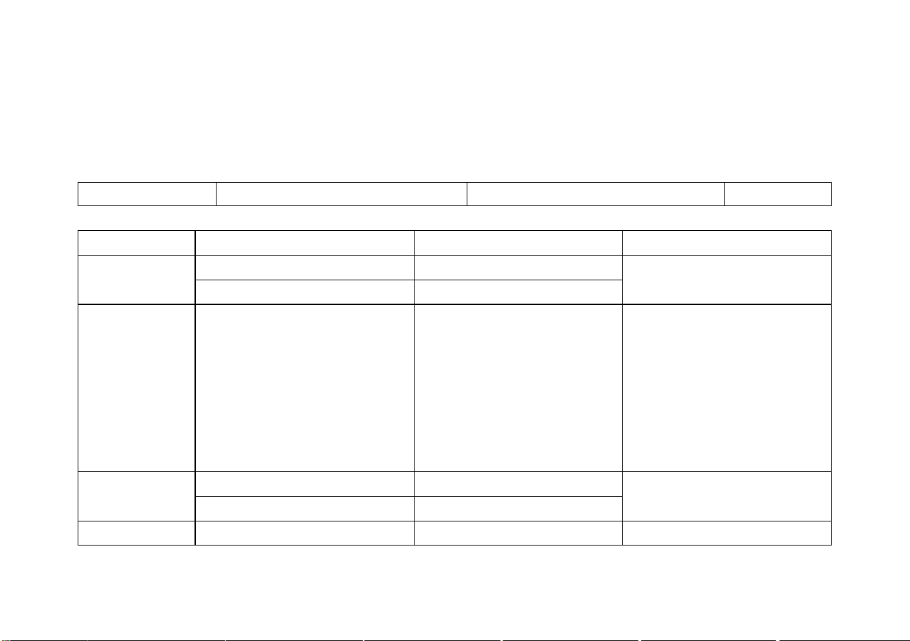
Measuring function
Input
Maximum limit
V DC
V/Ω,COM
1000V DC/AC peak, within 10 seconds
V AC
V/Ω,COM
750V DC/AC RMS, within 10 seconds
Hz
V/Ω,COM
380V DC/AC RMS, within 10 seconds
mA AC/ DC
400mA,COM
400mA DC/AC RMS, 250V/500mA fuse
A AC/ DC
10A,COM
10A DC/AC RMS, within 30 seconds, 15 minutes cooling interval,
250V/10A fuse
Ω / /
V/Ω,COM
250V DC/AC RMS, within 10 seconds
Capacitance/mF
V/Ω,COM
250V DC/AC RMS, within 10 seconds

2
4. When changing the measurement function, before inserting the probe plug and turning on and off the
multimeter, be sure to remove the probe from the test point;
5. Pay attention to the safety Warning signal displayed by the meter. When the measured voltage exceeds
DC1000V or AC750V, the buzzer will give long alarm; when the voltage range of DC1000V and AC750V
exceeds the safe voltage (24V), the buzzer will sound three times and the high voltage sign will be displayed
to alert the operator for safety;
6. When the voltage to the ground on the reference input “COM” of the meter is 500V, do not measure voltage
measurement;
7. Although the probe 10A range is connected with a 250V fuse, it is very dangerous to measure the voltage
incorrectly, which may damage the instrument;
8. When the current, resistance, continuity test, diode, capacitor and other positions are selected, never connect the
probe to both terminals of the voltage source;
9. Before performing resistance and diode/continuity tests, turn off the power to the device under test and
discharge the capacitor in the circuit.
10. Before opening the back cover to replace the fuse, turn off the power supply and disconnect the probe from the
circuit under test; replace the fuse with the same specifications;
11. Do not modify, disassemble or use the products and accessories for any purpose other than the design purpose
of the product. Do not replace parts and accessories at will;
12. Do not charge the battery. Replace the battery in time when the low voltage symbol is displayed on the
screen.
3
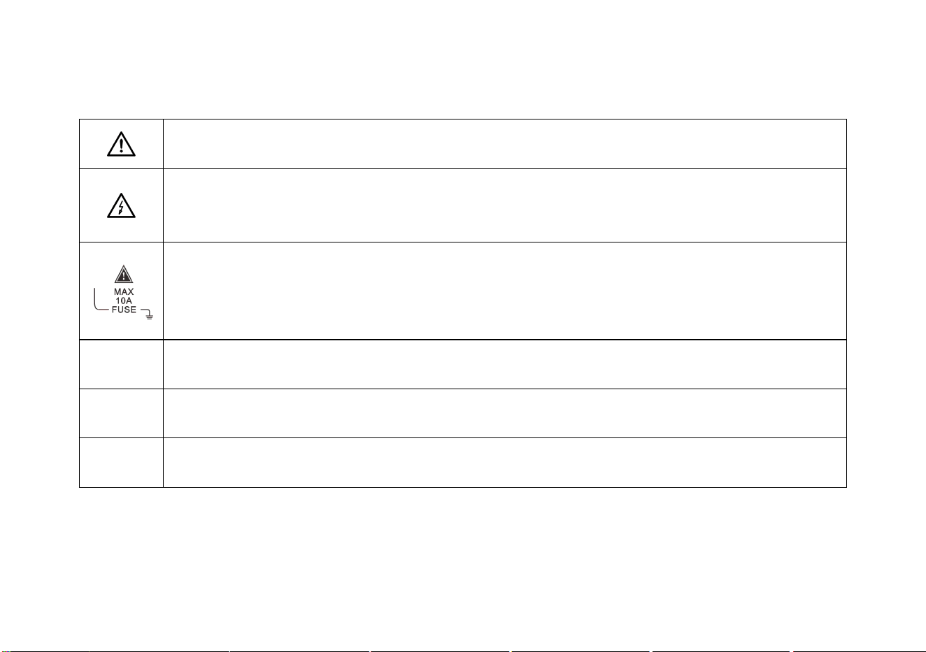
Safety signs
Caution! Danger! When this sign is found near other symbols or jack terminals, the users are
prompted to follow the instructions in this manual to prevent instrument damage/personal injury.
Caution! Electric shock! The presence of this sign near one or more terminals indicates that these
terminals may carry dangerous voltages during use. For the sake of safety, do not touch the test
probes of the probes when the terminals are energized.
This sign found near the terminal block indicates that the maximum withstand current between the
terminal and COM is 10A.
FUSE indicates a built-in 10A (or 500mA) fuse; current measurement is not allowed on circuits with
voltage of AC 250V or higher.
Prompt!
The prompt states that special care should be taken during operation. Incorrect operation can result in
erroneous measurement results or damage to parts.
Attention!
The attention states that care must be taken during operation in case of damage to this product and
other property.
Warning!
The Warning states that the operators should concentrate on the operation. Errors or violations may
result in personal injury or even life risk.
4
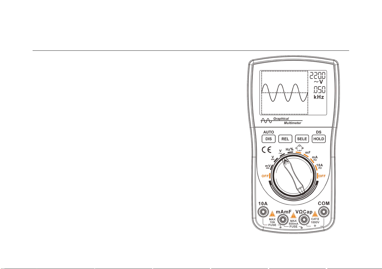
Instrument introduction
Features
◆ Digital multimeter with 200k high-speed A/D sampling,
4000 counts auto-range, one-button switch of graphical
waveform display during measurement
◆ High reliability with panel calibration technology and memory
calibration, sparing the need for adjustment with potentiometer
◆ Storing 100 sets of data and 10 waveforms independently
◆ Capable of holding waveform and data during measurement,
easy to view and analyze
◆ Realizing one-button automatic waveform capture,
operator-friendly to learn and operate

5
◆ Displaying historical data and real-time measurement on the
same screen with unique record reading mode for easy comparison
◆ Effectively eliminating lead resistance, distributed capacitance or interference signals with relative value
measurement (clearing)
◆ Extending battery life with automatic shutdown function
◆ Featuring DC/AC voltage/current, resistance, capacitance/mF (large capacitance)
Frequency/duty cycle, diode/continuity test
◆ Frequency measurement with 5Hz ~ 5MHz automatic switching range and the maximum input of 380VAC
◆ 10A AC and DC current measurement with protection against voltage error
◆ AC voltage bandwidth up to 20kHz
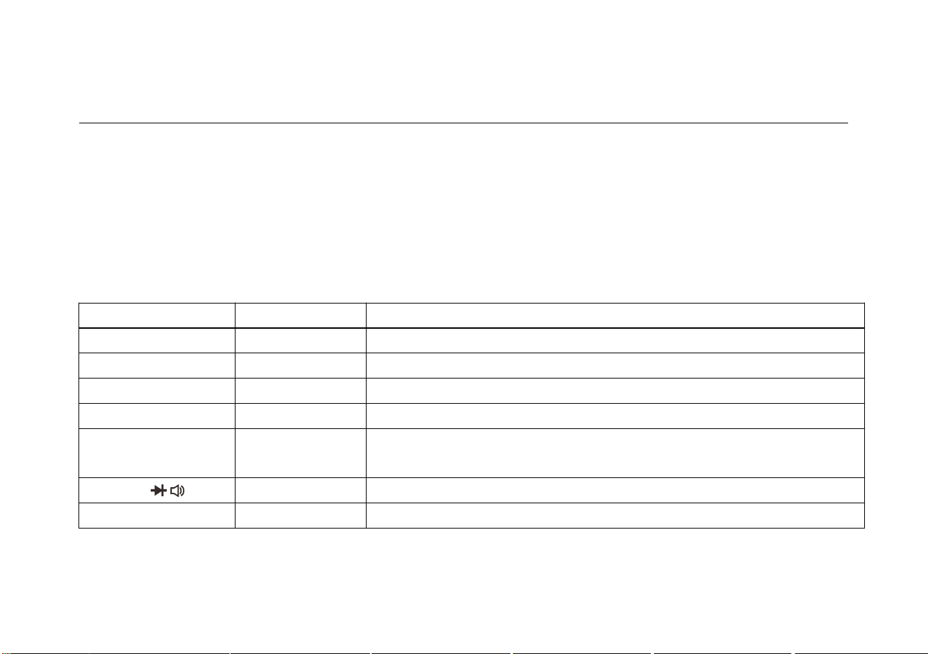
6
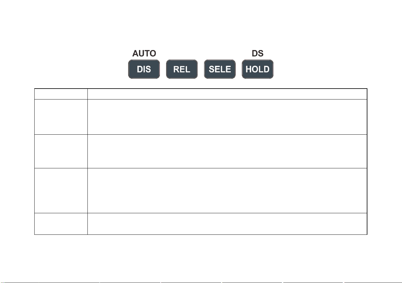
Buttons
NAME
FUNCTIONS
DIS/AUTO
1. Manually/automatically switching range during DMM measurement;
2. Switching between multimeter/graphical waveform display mode (Hold down);
3.Automatic capture during waveform measurement
REL
1. Showing relative value measurement during DMM measurement;
2. Paging up when reading stored data/waveform;
3. Scaling down the waveform and displaying period during waveform measurement
SELE
1. Selecting DC/AC mode;
2. Measuring frequency/duty cycle;
3. Paging down when reading stored data/waveform;
4. Scaling up waveform and displaying period during waveform measurement
HOLD/DS
1. Saving data/waveform;
2. Reading stored data/waveform (Hold down)
7
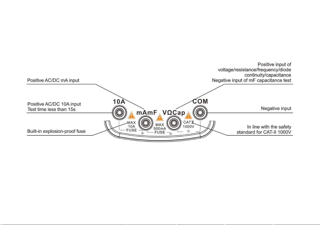
Insert plug
8
Basic Operation
Power on/off
Turn the knob to the desired measurement position to turn the multimeter on. Turn the knob to the "OFF"
position again to turn off the power.
Attention!
• Move the test probe away from the test point before turning the knob (shutdown).
• When the meter is used, turn off the power in time.
Automatic shut-down
If there is no button operation within the set 15 minutes, the meter will automatically shut down.
Tips
• Only the display of the main chip and LCD screen is turned off when the instrument is
automatically shut down, but there is still a certain leakage current.
• If it is not used for a long time, switch the knob to “OFF” position
Battery replacement
When the meter is in use and the low-voltage symbol appears in the upper right corner of the LCD screen,
the user should replace the battery as soon as possible.
When the meter is not used for a long time, take out the battery to prevent the battery from leaking and
damaging the meter.
Warning!
Pay attention to the safety of the battery.

9
Operation of Multimeter
Enabling the multimeter mode
Warning!
• Read, understand and follow the safety rules and practices outlined in the following context.
• When changing the measurement functions, be sure to remove the test probe from the test point.
Switching measurement functions
Rotate the function switch to select the measurement function and the appropriate range.
The voltage range includes 400mV, 4V, 40V, 400V and 1000V (Note that 750V RMS is available in AC
voltage measurement).
The frequency range is auto range from 5Hz to 5MHz
The capacitance range is auto range from 51.2nF to 100μF, and the large capacitance range is 10mF.
The current range is auto range from 40mA to 10A
The resistance range is auto range from 400Ω to 40MΩ.
Continuity test/diode detection

10
Relative value measurement (REL) mode
The relative value mode is a measurement mode that displays the difference between the measured value and
the reference value. Relative value mode is available for most functions of this meter.
1. After pressing the REL button, the measured value currently displayed is saved as a reference value and then the
relative value mode is activated.
2. The “▲” displayed on the LCD screen indicates that the relative value mode has been activated.
3. The value displayed on the screen is the difference between the current measured value and the reference value
saved previously.
4. Press the REL button again to exit the relative value mode.
5. When the measurement function or range changes, the relative value mode will be automatically disabled.
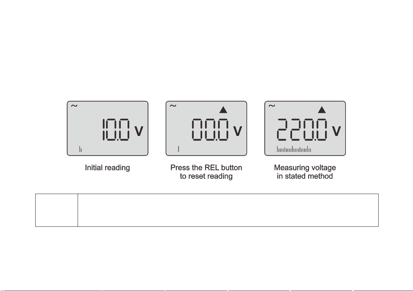
Application of relative value measurement (REL) mode
1. Voltage range: If the LCD display has the initial reading, enable the relative value function; press the REL
button, the LCD screen displays the “▲” symbol, and the initial reading is subtracted; “000” is displayed (Vary
in different ranges), and then perform measurement according to the voltage measurement method.
2. Resistance range: Turn the range to the resistance position; insert the test probes and contact the two metal
probes reliably (short circuit); observe the reading on the LCD, and press the “REL” button if there is an initial
reading; the “▲” symbol appears on the LCD screen. The initial reading is “000” (Vary in different ranges), and
11
then measure the resistance in the method stated.
3. Capacitance range: Turn the range to the capacitance position; insert the test probes and disconnect the two
metal probes; observe the reading on the LCD, and press the “REL” button if there is an initial reading; the “▲”
symbol appears on the LCD screen. The initial reading is “000” (Vary in different ranges), and then measure the
capacitance in the method stated.
Prompt!
• Some ranges are subjected to interference. It is normal that the reading is not reset or changes in a
small range after the relative value measurement is enabled.
• After the measurement is completed, pay attention to the relative value measurement status.

12
Holding and saving measurement data
The measurement can be held and saved with a single button. When the “HOLD” button is pressed, the reading
being displayed will be saved (This function cannot be used when there is no input in the frequency range), and the
icon “H00~H99” for data storage will appear on the LCD screen. Press the “HOLD” button again to resume normal
operation. However, the data is already stored in the internal memory.
1. To save the current measurement to the database, press the “HOLD” button to save this data.
2. After the data is held, hold down the “HOLD” button for 2 seconds to enable the database function, which can
display the saved data.
3. When the meter is in the data hold state, press “HOLD” to exit the data hold state; press and hold the “HOLD”
button to display the stored data.
4. When the range is switched or the measurement function is changed, the hold status is automatically disabled.
13
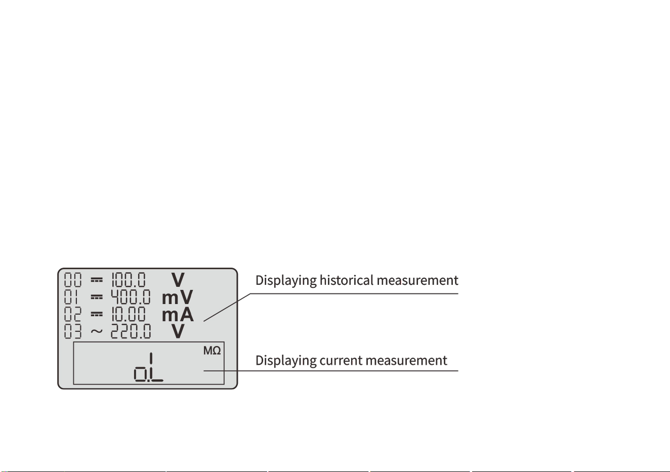
Reading and deleting measurement data
Reading measurement data;
The database can store 100 DMM measurement data.
1. Hold down the “HOLD” button for more than 2 seconds to enable the database.
2. When reading the data, a window (real-time measurement data window) appears in the lower part of the screen.
The data in this window is refreshed.
3. In the database, the four storage locations on this page and the data therein are indicated on the LCD.
4. If there is data stored in a location, the value and unit of this data will be listed.
5. Press the “REL/SELE” button, the sequence of the data will change from H00 to H99 in turn; 4 groups of stored
data are displayed per page.
6. To disable the stored data reading, press the “HOLD” button and stay for 2 seconds.
14
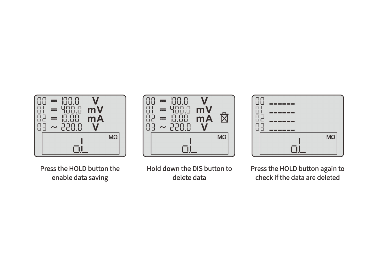
Deleting saved data;
1. Press the “DIS” button and hold it for more than 2 seconds. The LCD displays the “Recycle Bin” icon.
2. Press the “HOLD” button to delete the stored data.
3. The data cannot be deleted in a single line or on a single page. Once the data deletion is enabled, all stored data
(H00~H99) in the memory will be deleted.
4. After the deletion is completed, the measurement status is automatically entered.
15
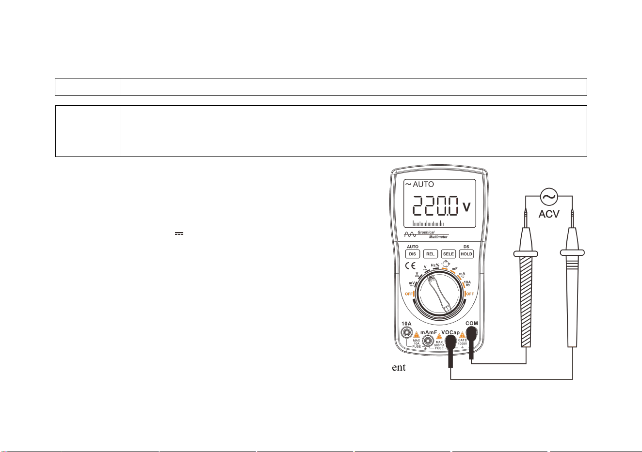
AC and DC voltage measurement
Prompt!
Pay attention to safety when measuring voltage exceeds “safe voltage” (24V).
1. Insert the banana plug of the black test probe into the negative COM
jack and insert the plug of the red test probe into the positive V jack.
2. Rotate the function switch to select the ACV or DCV function.
When selected, the ~ or symbol will appear in the upper left
corner of the screen.
3. Contact the test point with the test probe.
4. Read out the voltage value displayed by the meter.
The displayed results include values, decimal points, and polarity.
Diagram of AC voltage measurement
Warning!
• To avoid damage to the meter, do not apply 750V AC or 1000V DC voltage to the measuring
terminal for more than 10 seconds.
• Take care when the measured voltage reaches the limit.
16
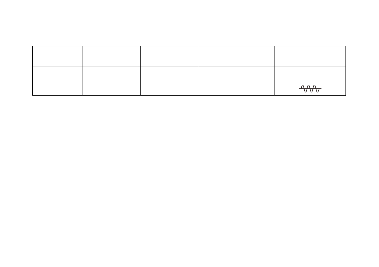
The menu for voltage measurement:
Function
Relative value
mode
Holding/reading
data
Manual/automatic
switching
Waveform display
function
Button
REL
HOLD
AUTO
DIS(Hold down)
Display
▲
H00~H99
AUTO/---
a. Press the “REL” button to enable the relative value mode.
b. Press the “HOLD” button to enable the data holding; hold down the “DS/HOLD” button to enable the data
storage and waveform storage list.
c. If the graphical waveform display mode is selected (Enabled only in
automatic range state), hold down the “DIS” button to display the
waveform and data of the current voltage.
d. Press/hold down the “DIS/AUTO” button to enable manual/auto range.
17
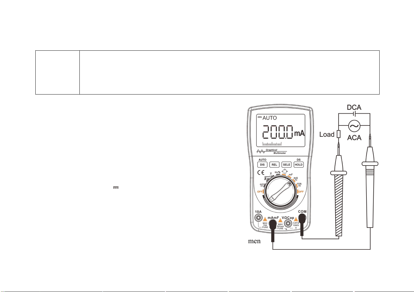
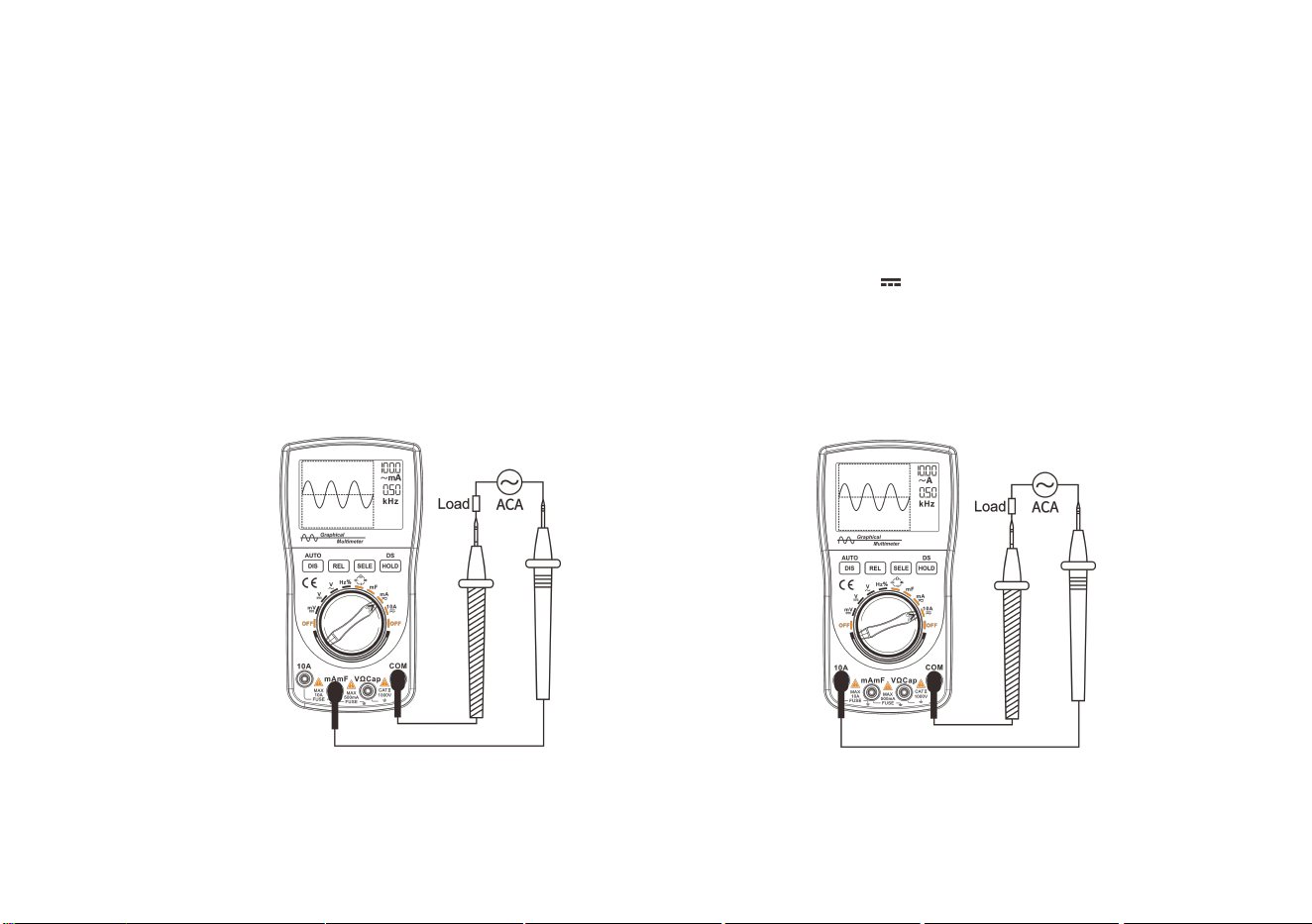
AC and DC current (mA, 10A) measurement
Warning!
• Do not measure voltage with the 10A input; do not measure AC current on circuits with AC
250V or above voltage.
• When using the 10A current range, the measurement time should not exceed 15 seconds every 15
minutes, otherwise the meter and test probes may be damaged.
1. Insert the connecting plug of the black test probe into the negative
COM jack and insert the banana plug of the red test probe into
the positive mA jack. (Insert into the 10A jack when measuring
10A current)
2. Rotate the function switch based on the size of the test signal
and point the arrow on the knob to the 400mA/10A range.
3. Press the “SELE” button to select the AC or DC measurement.
When selected, the ~ or symbol will appear in the upper left
corner of the screen.
4. Connect the test probes into the circuit under test in series.
5. Read the current value displayed on the meter. The displayed results
include values, decimal points, and polarity.
Diagram of mA current measuremen
18
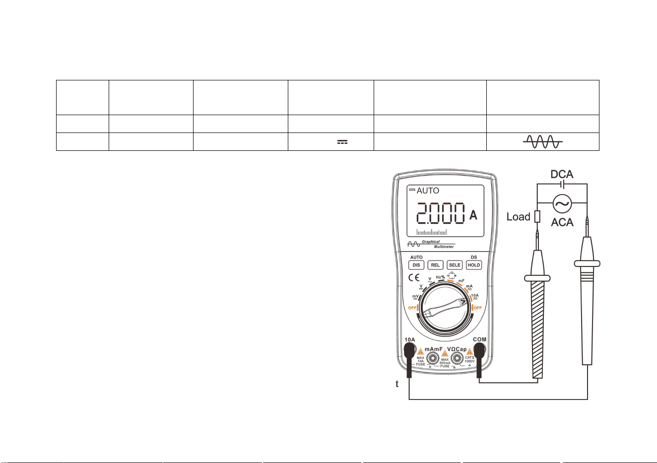
The menu for current measurement:
Functio
n
Relative value
mode
Holding/reading
data
AC/DC
conversion
Manual/automatic
switching
Waveform display
function
Button
REL
HOLD
SELE
AUTO
DIS(
Hold down
)
Display
▲
H00~H99
~ /
AUTO/---
a. Press the “REL” button to enable the relative value mode.
b. Press the “HOLD” button to hold data; hold down the “DS/HOLD”
button to enable data storage and waveform storage list.
c. Press the “SELE” button to select the AC or DC measurement
function.
d. If you select the graphical waveform display mode (only in
automatic range state); press and hold the “DIS” button to display
the waveform and data of the current voltage.
e. Press/hold down the “DIS/AUTO” button to enable the manual/auto
range.
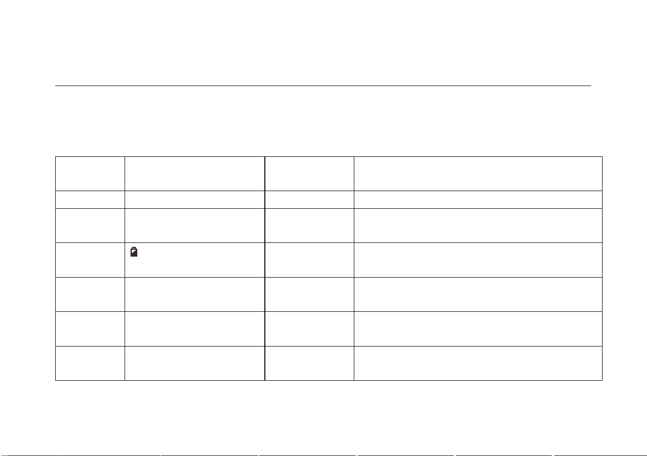
Diagram of 10A measurement
19
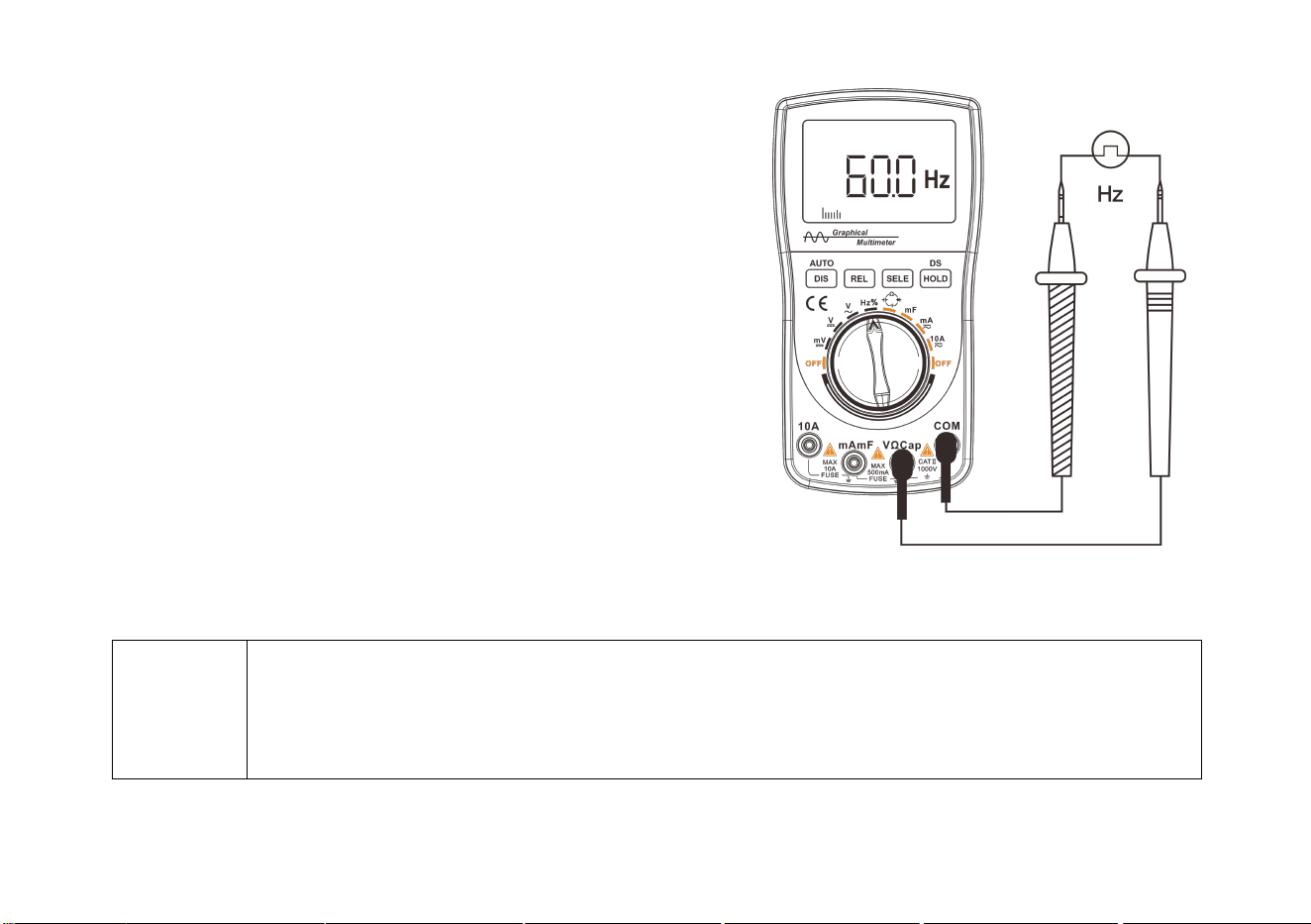
Frequency/duty cycle measurement
Frequency measurement is an extended function
of AC voltage measurement.
1. Insert the connecting plug of the black test probe into the negative
COM jack and the connecting plug of the red test probe into
the positive V jack.
2. Rotate the function switch and point the arrow on the knob to
the Hz/% range (Press the “SELE” button to switch between
the frequency “Hz” and duty cycle “%” function).
3. Touch the test point with the test probe.
4. Read the frequency value displayed on the meter.
The displayed results include values, decimal points, and polarity.
Diagram of frequency measurement
Prompt!
• The graphical waveform display method cannot be used in frequency count measurement, and the
relative value (REL) function cannot be used either!
• In the frequency measurement, the amplitude of the signal under test shall not be less than 2Vp-p,
and the maximum input voltage shall not be lower than 380V.
20
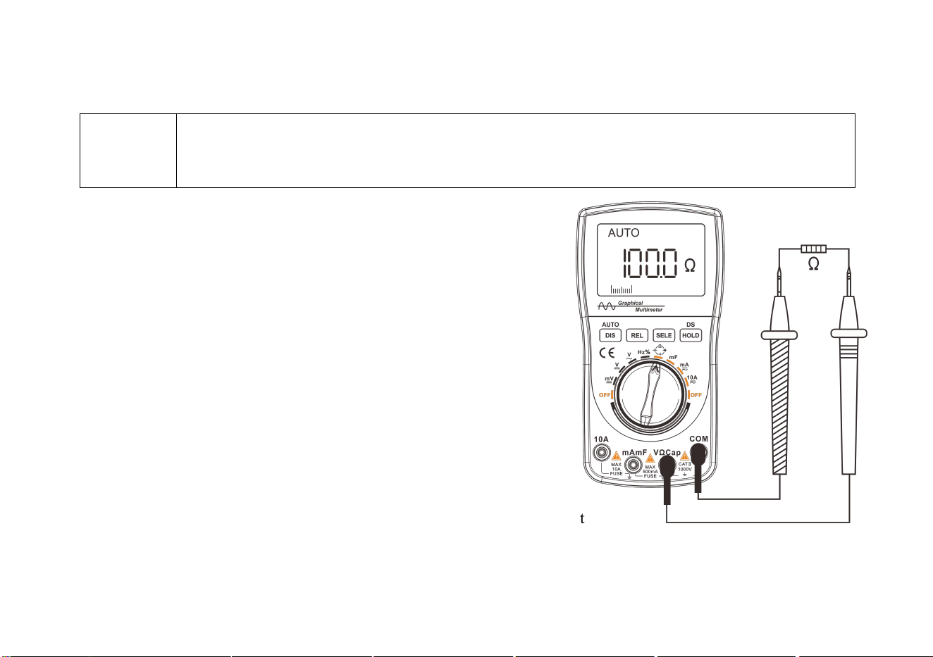
Resistance measurement
Warning
To avoid electric shock, when performing resistance measurements, first turn off the power to the
device under test (Disconnect the battery/unplug the power cord) and discharge the capacitor in the
power supply.
1. Insert the connecting plug of the black test probe into the
negative COM jack;
Insert the connecting plug of the red test probe into the
positive resistance Ω jack.
2. Connect a test probe to the circuit or component under test.
Disconnect one end of the component to be tested from the
original line to ensure that the rest of the circuit does not
affect the correctness of the reading.
3. Read the resistance value, unit and decimal point displayed
on the meter.
Diagram of resistance measurement
21
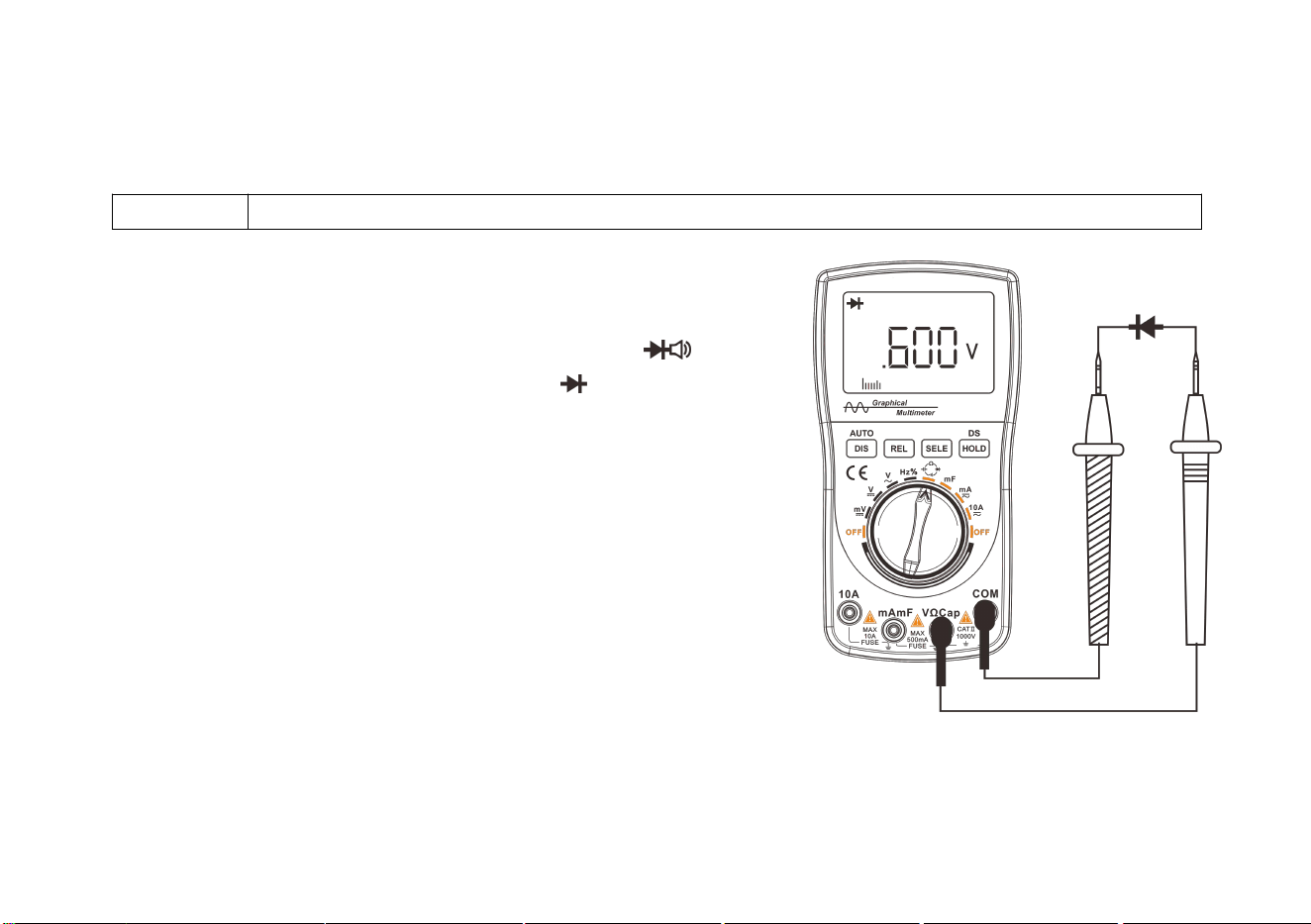
Diode/continuity test
Diode test
Warning!
To avoid electric shock, do not test the diode carrying the voltage.
1. Insert the connecting plug of the black test probe into the negative
COM jack; insert the banana plug of the red test probe into
the positive resistance Ω jack.
2. Rotate the switch, point the arrow on the knob to the Ω Cap range,
and press the “SELE” button to switch to the range.
3. Connect the test probe to both ends of the diode or semiconductor’s
PN junction under test. Pay attention to the readings of the meter.
4. Swap the positions of the test probes to reverse the polarity.
Pay attention to the readings.
5. The nature of the diode or semiconductor’s PN junction can be
judged as follows:
If the reading in the first measurement is a voltage value
(approximately 0.2V to 0.7V), and the reading in the second
measurement shows “.0L”, the diode can be used normally.
If the readings in both measurements are “.0L”, the diode is opened circuited.
If the readings in both measurements are slight or ".000", the diode is shorted. Diagram of diode measurement
22
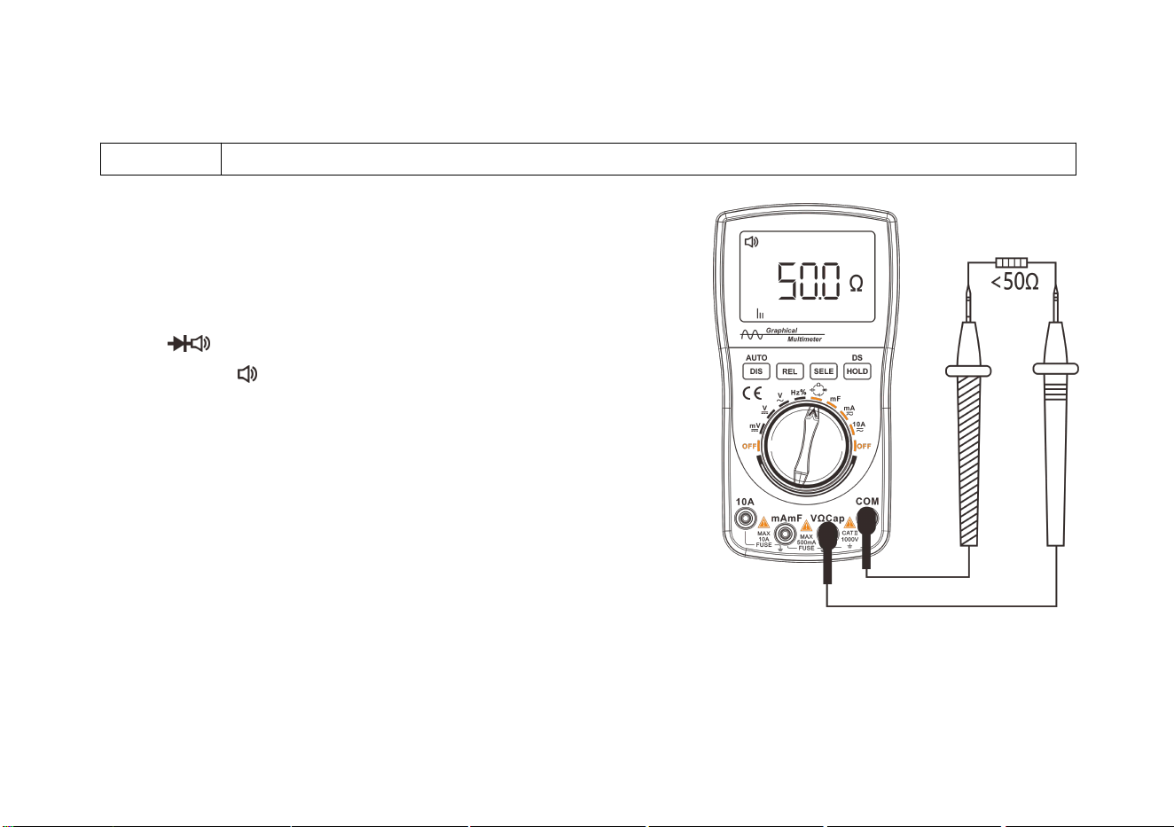
Continuity test
Warning!
To avoid electric shock, do not test the continuity on the line carrying voltage.
1. Insert the connecting plug of the black test probe into the
negative COM jack; insert the connecting plug of the red test
probe into the positive resistance Ω jack.
2. Rotate the function switch, point the arrow on the knob to
the Ω Cap range, and press the “SELE” button to
switch to the range.
3. Contact the circuit under with test probes. If the resistance is
lower than 50Ω, the buzzer will beep.
Diagram of continuity test
23
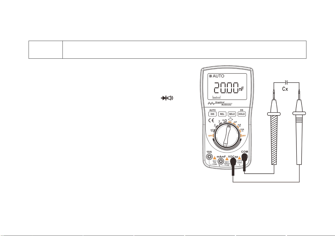
Capacitance measurement
Warning!
To avoid electric shock, do not test the capacitor carrying voltage. Discharge the capacitor shortly
before measuring the large capacitor.
1. Insert the connecting plug of the red test probe into the positive
Cap jack and the connecting plug of the black test probe
into the COM jack.
2. Rotate the function switch to point the arrow to the Ω Cap range;
press the “SELE” button again to switch to the Cap range.
3. Measure the small capacitance; press the "REL" button to remove
the lead resistance and distributed capacitance before measurement.
4. Contact the test probe and the metal lead of the capacitor under test.
5. Read the capacitance value displayed on the meter. The displayed
results include values, decimal points, and polarity.
Diagram of capacitance measurement
24
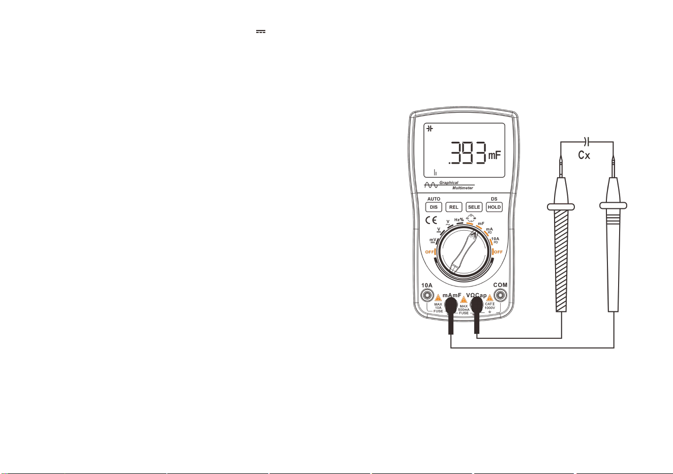
mF (large capacitance) measurement
1. Insert the connecting plug of the red test probe into the positive mF jack,
and the connecting plug of the black test probe into the Cap jack.
2. Rotate the function switch and point the arrow on the knob
to the mF range.
3. To measure the small capacitance, press the "REL" button
to remove the lead resistance and distributed capacitance
before measurement.
4. Contact the test probe and the metal pins of the capacitor under test.
5. Read the capacitance value displayed on the meter.
The displayed results include the value, decimal point and polarity.
Diagram of mF capacitance measurement
25
Waveform display operation
Enabling waveform display mode
Hold down the “DIS” button for 2 seconds to select the waveform display mode.
Prompt!
The waveform display function is only available in the voltage/current range.
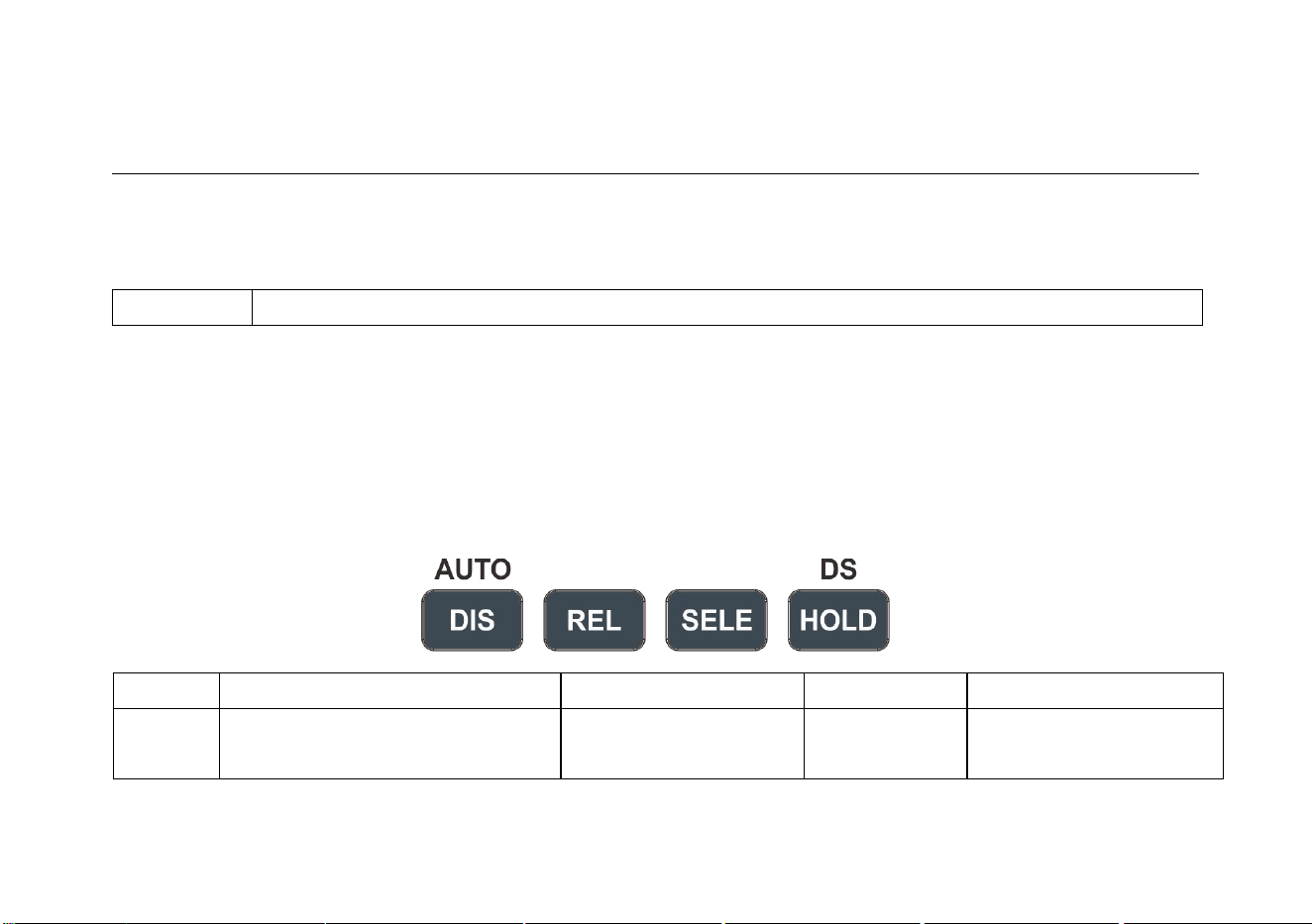
Buttons and main menu
The buttons for waveform display are located in the lower part of the LCD screen, which can be in combination to
realize a variety of functions.
The basic operations are described specifically as follows:
Button
DIS
AUTO
REL/SELE
HOLD
Function
Enabling waveform display (Hold
down)
Displaying stable
waveform
Change time
base
Saving waveform (10
groups)
26
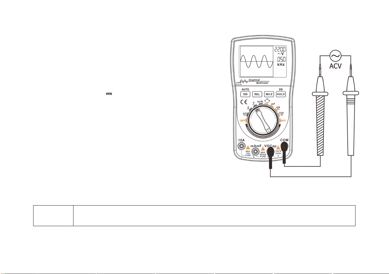
Waveform of voltage measurement
1. Insert the connecting plug of the black test probe into the negative
COM jack; insert the connecting plug of the red test probe into the
positive V jack.
2. Rotate the function switch to select the AC or DC range.
When selected, the ~ or symbol will appear in the upper
left corner of the screen.
3. Touch the test point with the test probe.
4. Hold down the “DIS” button for 2 seconds (Enable the waveform
display mode in auto-range state).
The waveform of the current voltage can be displayed.
Waveform of voltage measurement
Tips
Only repeatable waveform can be measured for DC voltage (DCV); when measuring waveform,
press the “DIS” button several times to automatically capture the waveform.
27
Waveform of current measurement
1. Insert the connecting plug of the black test probe into the negative COM jack, and insert the connecting plug of
the red test probe into the positive mA/10A jack.
2. Rotate the switch. Depending on the size of the test signal, point the arrow on the knob to the mA/10A range.
3. Press the “SELE” button to select the AC or DC range. When selected, the ~ or symbol appears in the upper left
corner of the screen.
4. Connect the test probes into the circuit under test in series.
5. After holding down the “DIS” button for 2 seconds (Enable the waveform display mode in auto-range state), the
waveform and data of the current can be displayed.
Waveform of mA current measurement Waveform of 10A current measurement

28
Automatic measurement of waveform
The multimeter can automatically measure the amplitude and frequency of the current waveform, and the
measurement results are displayed in the right side of the waveform display area.
The waveform measurement is the effective value directly sampled by the multimeter A/D.
Press the “DIS” button to display a stable waveform on the LCD.
Holding and saving signal waveform
The main purpose of holding waveform is to hold the current waveform for closer observation. Save the current
waveform when you need to save it in the database.
Method of holding waveform: Press the "HOLD" button, the waveform is held/stored; H0~H9 are displayed in
the lower right part of the LCD screen, indicating the order in which the 10 waveform groups are stored.

29
Saving and reading signal waveform
The database of the instrument has a memory capacity for 10 waveform groups, which can be saved as follows:
1. Press the “HOLD” button to enable the waveform hold/storage function.
2. Press the “HOLD” button and hold for 2 seconds to enter the waveform database.
3. The locations of the 10 waveform groups from H0 to H9 will be listed on the display.
4. If there is data stored in the selected position, the thumbnail of the waveform and the associated parameters will be
displayed in the waveform preview area. When there is no data in the memory location pointed by the selection
marker, blank coordinates will be displayed in the waveform preview area.
Deleting signal waveform saved
1. Press the “DIS” button and hold for more than 2 seconds. The Recycle Bin icon appears on the LCD.
2. Press the “HOLD” button to delete the data in the memory.
3. The data cannot be deleted in a single line or on a single page. Once the data deletion is enabled, all stored data
(H0~H9) in the memory will be deleted.
4. After the deletion is completed, the measurement status is automatically entered.
30
Technical Parameters and Packing List
Features and technical parameters
General features
Display
128
64 dot matrix graphic
LCM
Viewing area
60mm x40mm
Backlight
White
Input resistance
10MΩ
Battery
3 AA batteries
Automatic
shutdown
Yes (The meter automatically shuts down in 15
minutes without any operation of button)
Low power
Power
consumption
About 40mA
Battery life
Approx. 30 hours
Storage capacity
DMM data:100 groups, waveform record: 10
groups
Operating
environment
0°C~+40°C;<75%RH
Storage
conditions
-10°C ~ +60°C ; <90%RH
Dimensions
83 mm
160 mm
32mm
Weight
Approx. 190g (without battery and other
accessories)
31
Features of digital multimeter
All range uncertainty is expressed in ± (a% reading + unit). The calibration interval is one year.
Environmental conditions for guaranteed uncertainty: 23 ° C ± 5 ° C, < 75% RH.
Analog Bandwidth
ACV/DCV/ACA/DCA 20kHz
Maximum Real-Time Sampling Rate
200ksps
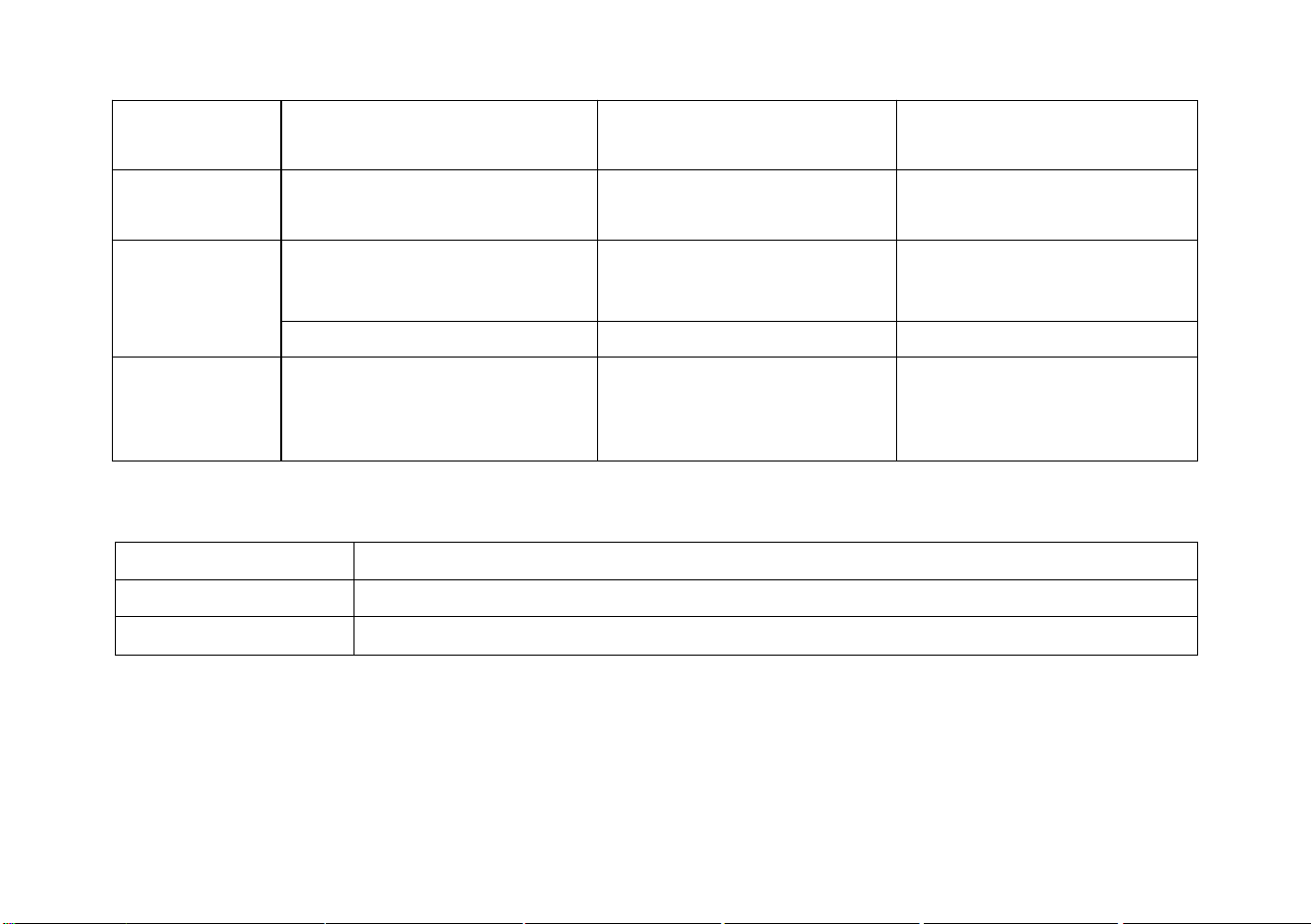
Features
Range
Resolution
Uncertainty
DC voltage
400mV
0.1mV
(0.75%rdg + 10dgt)
(1.5%rdg + 10dgt)/1000V
4V/40V/400V/1000V
1mV/10mV/100mV/1V
AC voltage
400mV/4V/40V/400V/750V
0.1mV/1mV/10mV/100mV/
1V
50Hz~400Hz
(1.0%rdg + 10dgt)
400Hz~20kHz (not checked
above 20kHz)
(5.0%rdg + 10dgt)
50Hz~400Hz/750V
(1.5%rdg + 10dgt)
DCA
40mA /400mA
10µA /100µA
(1.2%rdg + 10dgt)
4A/10A
1mA/10mA
ACA
40mA /400mA
10µA /100µA
(1.5%rdg + 10dgt)
32
50Hz~5kHz (not checked
above 5kHz)
4A/10A
1mA/10mA
Resistance
400/4K/40K/400K/
4M/40M
0.1Ω/1/10/100/1K/
10k
(1.0%rdg + 5dgt)
(3.0%rdg + 5dgt)/40M
Capacitance
51.2nF/512nF/5.12μF/51.2μF/
100μF
10pF/100pF/1nF/10nF/100nF
(2%rdg + 10dgt)/51.2nF
(1%rdg + 3dgt)
10mF
1μF
(5%rdg + 3dgt)
Frequency
5Hz~5MHz
1Hz
(1.0%rdg + 5dgt),(Signal
amplitude not less than
2Vp-p, AC V, MAX380V)
Diode test
Open circuit voltage: about 1.5 V, maximum test current: about 1.5mA
Continuity test
Reference resistance: about 50Ω
Fuse specification
500mA/250V ,10A/250V
33
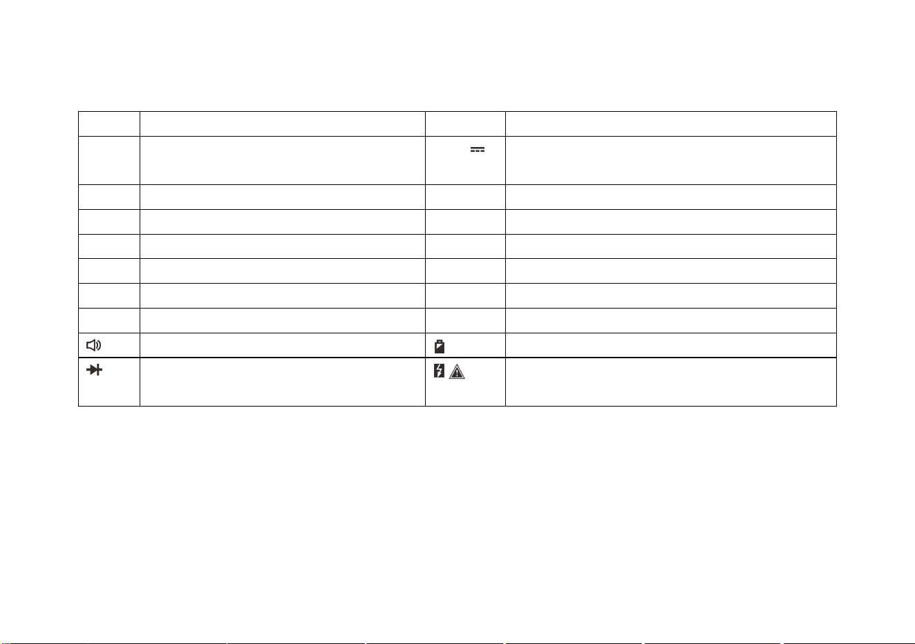
Description of symbols and icons
A
Ampere (unit of current)
AC ~
AC
COM
Measuring reference (near the input
reference jack)
DC
DC
F
Farah (unit of capacitance)
mF
mF (unit of capacitance)
HOLD
Data/holding waveform
Hz
Hz (unit of frequency)
mA
mA (unit of current)
%
Duty cycle
nF
nF (unit of capacitance)
mV
mV (unit of voltage)
V
Volt (unit of voltage)
▲
Relative value (clearing))
Ω
Ohm (unit of resistance)
μF
μF (unit of capacitance)
Buzzer, continuity test
Remaining power of battery
Diode
Safety warning (Reminder of hazardous or limit
voltage and current)
Packing list
One MT8206 unit, one bag, one pair of probes, one copy of Operator’s Manual and package box