OPERATOR’S MANUAL
For technical assistance or the Water Maze Dealer nearest you,
consult our web page at www.wmaze.com
■
CL-304
CL
8.913-972.0-A
Rev. 4/15
CLARIFIER-304
VOLTAGE
SUMP PUMP
FILTER PUMP
TRANSFER PUMP
®
ON
PRENDER
OFF
I
O
ON
PRENDER
OFF
I
O
ON
PRENDER
OFF
I
O
OPERATING INSTRUCTION
S
INSTRUCCIONES DE OPERACIO
N
INSTRUCTIONS D' OPERATIO
N
Assembled in USA
Contains components from one or more of
the following countries: United States,
Austria, Brazil, Canada, China, England ,
France, Honduras, Italy, Japan, Mexico,
Romania, Taiwan, Thailand, Vietnam.
INTENDED FOR INDOOR USE
89139720-15

CONTENTS
2
WATERMAZE CL-304 • 8.913-972.0-A
Introduction 5
Unpacking 5
Safety Instructions 5-6
System Safety Information 6
Installation Instructions 7
Water Panel Identification 8
Installation View 9
Component Identification 10
Operation 11
Float Level Controls 11
Valve Location and Function 11-12
Filling System with Water 12
View of Sump with Floats 12
Electrical 12
Check List Before Starting 13
Start Up 13
General Maintenance and Service 13-14
Periodic Maintenance 13
Cartridge Filter 13
Filtering 13
Remove/Replace Cartridges 13-14
Cleaning Cartridges 14
Winterizing 14
Chemical Maintenance Program 14-15
Daily Chemical Maintenance 15
Pump Operation (Filter or Transfer) 15-16
Pump Maintenance (Sump) 16
Pressure Switch Operation 16
Pressure Tank Operation 16-17
Automatic Chlorine Dispenser 17
Pump Plumbing Breakdown Exploded View and Parts List 18-19

3
CONTENTS
WATERMAZE CL-304 • 8.913-972.0-A
Model Number ______________________________
Serial Number ______________________________
Date of Purchase ____________________________
The model and serial numbers will be found on a decal attached
to the machine. You should record both serial number and date of
purchase and keep in a safe place for future reference.
Cone Assembly Breakdown Exploded View and Parts List 20-21
Holding Tank Breakdown Exploded View and Parts List 22-23
Filter Tank Exploded View and Parts List 24-25
Water Panel, Exploded View and Parts List 26-27
Electric Control Panel, Exploded View and Parts List 28-29
Submersible Sump Pump Specification 30
Filter Pump, Exploded View and Parts List 31
Cartridge Filter Assembly, Exploded View and Parts List 32
Multi-Media Filter, Exploded View and Parts List 33
Valve, 6-Way, Exploded View and Parts List 34
Sanitizer 35
Transfer Pump, Exploded Views and Parts List 36
Troubleshooting 37-43
CL-304 37
Pump 38
Pump Motor 39
Filter 40
Water Solenoid 41
Water Seals 42
Outlet to Pressure Washer 43
Specifications 44
Consumable Parts List 44
Warranty 45
WATERMAZE CL-304 • 8.913-972.0-A
OPERATOR’S MANUAL WATER TREATMENT SYSTEM
4
INTRODUCTION & IMPORTANT SAFETY INFORMATION
Your owner’s manual has been prepared to provide
you with a simple and understandable guide for equip-
ment operation and maintenance, based on the latest
product information available at the time of printing. To
keep your machine in top running condition, follow the
specific maintenance and troubleshooting procedures
given in this manual.
SAVE THESE INSTRUCTIONS
This manual should be considered a permanent
part of the machine and should remain with it if
machine is resold.
When ordering parts, please specify model and
serial number. Use only identical replacement parts.
This machine is to be used only by trained operators.
Owner/User Responsibility:
The owner and/or user must have an understanding of
the manufacturer’s operating instructions and warnings
before using this WATER MAZE machine. Warning
information should be emphasized and understood.
If the operator is not fluent in English, the manufac-
turer’s instructions and warnings shall be read to and
discussed with the operator in the operator’s native
language by the purchaser/owner, making sure that
the operator comprehends its contents.
The owner and/or user must study and maintain the
manufacturers’ instructions for future reference.
NOTE: WATER MAZE reserves the right to make
changes at anytime without incurring any obligations.
UNPACKING
1. Coalescing Cone Assembly
2. Sump Pump Assembly
3. Oil Water Decanter Barrel
4. Waste Collection Bag and Pan
5. Exterior Plumbing
6. Fresh Water Make-up Float
7. High Level Control Float
8. Test Strips
9. Operator’s Manual
Note any damage to machine or components for
claims against the freight lines.
IMPORTANT SAFETY
INSTRUCTIONS
CAUTION: To reduce the risk of
injury, read operating instruc-
tions carefully before using.
1. Read owner’s manual thor-
oughly. Failure to follow the
instructions will cause a mal-
function of the machine and
result in death, serious injury
and/or property damage.
WARNING: Follow the wiring
instructions in this manual when
connecting the system to the
power lines.
WARNING: All wiring must be
performed by a qualified electri-
cian.
WARNING: Machine must be
electrically grounded.
2. The installation of this machine must comply with
local and/or national codes.
3. The machine, when installed, must be electrically
grounded in accordance with local and/or national
codes. Do not spray water near any electrical com-
ponents.
4. Never make adjustments on the machine while it
is in operation, except for those prescribed in this
manual.
WARNING
HAZARDOUS
VOLTAGE. CAN
SHOCK, BURN OR
CAUSE DEATH.
READ OPERATOR'S
MANUAL
THOROUGHLY
PRIOR TO USE
CAUTION
READ CAREFULLY
This feeder is designed to use only Trichloro-s-triazinetrione OR
Bromine tablets-slow dissolving type UNDER NO CIRCUMSTANCES
mix Trichlor OR Bromine with Calcium Hydroclorite,
with other forms of concentratedd chlorine OR with
other chemicals FIRE AND EXPLOSION MAY
RESULT. NEVER use oils or grease to lubricate O-
ring. Oil in contact with Trichlor OR Bromine may result
in fire. Lubricate O-ring with Lifegard Silicone O-ring
Lubricant only, available at your dealer. Caution should be used when
removing feeder cap. Do not inhale fumes. If shock treatments
or Algaecides containing chemicals other than sanitizer tablets in
feeder must be used, turn off Feeder OR remove tablets until the
shock or Algae treatment is complete and all granules have dissolved.
Failure to do so may result in granules mixing in feeder causing
FIRE AND/OR EXPLOSION. The shock or Algae treatment dissolved
in water is safe with tablets.
WATERMAZE CL-304 • 8.913-972.0-A
5
WATER TREATMENT SYSTEM
OPERATOR’S MANUAL
WARNING
RISK OF
EXPLOSION: DO
NOT USE WITH
FLAMMABLE
LIQUIDS
IMPORTANT SAFETY INFORMATION
WARNING: Do not discharge con-
centrations of flammable or ex-
plosive fluids such as gasoline,
fuel oil, kerosene, etc. into the
CL-304. Do not use in explosive
atmospheres. Failure to follow
this warning can produce an
explosion resulting in personal
injury and/or property damage.
5. Do not discharge gasoline or other volatile hy-
drocarbons into the CL-304. This could cause a
gas vapor build-up inside the CL-304 which could
become an explosive mixture.
6. Before servicing the machine, refer to the MSDS’s
on all the material identified in the waste stream.
You must comply with all warnings and wear all
protective clothing as stated on the MSDS’s.
7. Protect inlet and outlet pipes from vehicle traffic
and sharp objects.
8. Inlet water temperature must not exceed 100° F.
9. When making repairs, disconnect this machine
from its electrical source.
10. The best insurance against an accident is precau-
tion and knowledge of the equipment.
11.
WATER MAZE is not liable for modifications or the use
of components not purchased from WATER MAZE.
12. This machine will freeze and must be located in a
heated enclosure in cold climates.
13. Running the system without water will damage the
pumps and will void the warranty.
At the time of installation, the flow into the CL-304
must be set.
NOTE: Maintenance and water tests must be done
routinely.
SYSTEM SAFETY
INFORMATION
1. Know the system application, limitations and po-
tential hazards.
WARNING: Do not use to pump
concentrations of flammable
or explosive fluids such as
gasoline, fuel oil, kerosene,
etc. Do not use in explosive
atmospheres. Pumps should
only be used with liquids com-
patible with pump component
materials. Failure to follow this
warning can result in personal injury and/or
property damage.
2. Make certain power source conforms to CL-304
electrical requirements. (Check the serial plate for
proper voltage and amperage requirements.)
3. Disconnect the power before servicing.
4. Release all pressure within the system before ser-
vicing any component.
5. Drain all liquids from components before servicing.
6. Check hoses for weak or worn condition before
each use, making certain that all connections are
secure.
7. Periodically inspect pump and system components.
Perform routine maintenance as required.
WARNING: Wear protective
eyewear, foot protection and
protective clothing.
8. Personal Safety:
a. Wear safety glasses
and other applicable
protective clothing at all
times when working on the
CL-304. NOTE: Refer to item
#6 under Safety Instructions.
b. Keep your work area clean, uncluttered and
properly lighted. Replace all unused tools and
equipment.
c. Keep visitors at a safe distance from the work
area.
d. Make the workshop safe with padlocks and
master switches.
9. When wiring an electrical system, follow all electrical
and safety codes, as well as the most recent Na-
tional Electrical Code (NEC) and the Occupational
Safety and Health Act (OSHA).
WARNING: Risk of electric shock.
10. All wiring should be performed by a qualified electri-
cian.
11. The main power must be brought from the circuit
breaker and wired into the electrical box on the
CL-304. This line must be run through conduit to
protect it from damage. A power disconnect should
be located next to the machine for maintenance
purposes.
12. Protect all electrical cords from sharp objects, hot
surfaces, oil, sunlight and chemicals. Avoid kink-
ing the cords. Replace or repair damaged or worn
cords immediately. All wiring should be run through
conduit.
13. Use wire of adequate size to minimize voltage drop
at the motor.
WARNING
RISK OF EXPLOSION:
DO NOT USE WITH
FLAMMABLE
LIQUIDS
WARNING
USE PROTECTIVE
CLOTHING WHEN
OPERATING
EQUIPMENT

WATERMAZE CL-304 • 8.913-972.0-A
OPERATOR’S MANUAL WATER TREATMENT SYSTEM
6
14. Disconnect the power before servicing a motor. If
the power disconnect is out-of-sight, lock it in the
open position and tag it to prevent unexpected ap-
plication of power.
15. Do not touch an operating motor. Modern motors
are designed to operate at high temperatures.
16. Do not handle a pump or pump motor with wet
hands or when standing on a wet or damp surface
or in water.
17. The pump motors are equipped with an automatic
resetting thermal protector and may restart unex-
pectedly. Tripping is an indicating of motor over-
loading as a result of operating the pumps at low
heads (low discharge restriction), excessively high
or low voltage, inadequate wiring, incorrect motor
connections or a defective motor or pump.
18. IMPORTANT NOTE: The sump pump is not a trash
pump and is subject to premature failure unless
sump baffling or additional protection is provided.
IMPORTANT SAFETY INFORMATION

WATERMAZE CL-304 • 8.913-972.0-A
7
WATER TREATMENT SYSTEM
OPERATOR’S MANUAL
INSTALLATION INSTRUCTIONS
sump, the higher the float must be placed above
the suction intake. On three phase units a third
float is needed to protect the sump pump from the
possibility of running dry. Position the Low Water
Protect Float #7 (black, normally open) 6" above
the suction inlet of sump pump. Single phase sump
pumps have a float built into them.
Floats must travel their complete arc without:
• Water going over the top of the pit.
• Touching side walls or bottom.
• The pit running out of water.
• Interfering with electrical wiring, plumbing, bot-
tom or side walls of sump, or any object. Attach
the floats to the PVC line on the sump pump.
Check to assure the floats can operate freely.
(See CL-304 Installation View.)
9. Run the electrical cords from the sump pump and
floats to the electrical junction boxes near the return
line and attach wires. (See electrical diagram). If the
sump pump and floats are located farther then 20
feet from the electrical junction boxes, then have
an electrician install water tight junction boxes with
conduit and proper sized wire to extend the electri-
cal connections.
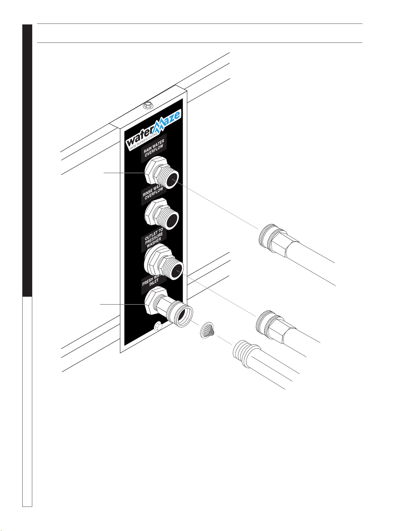
10. Connect the fresh water line (3/4" GHM garden
hose not provided) to the “Fresh Water Makeup”
port on the water panel (see Water Panel Illustra-
tion).
11. Connect the “Outlet to Pressure Washers” to your
pressure washer by using a 5/8" garden hose (not
provided). Valve #7 behind the water panel should
remain closed until start-up.
12. Connect the “Rain Water Overflow” to a sewer or
to storage (line not provided). Valve #8 behind the
water panel should remain halfway open.
CAUTION: Discharge permits are required and
must be obtained before any treated water is
discharged.
13. Connect a hose to “Rinse Water” outlet if it is to be
used. Make sure valve #6 behind the water panel
stays closed until rinse water is needed (hose not
provided).
NOTE: The use of rinse water in a closed loop
system will overfill the system and will lead to an
overflow situation causing the rainwater overflow
valve to open.
1. Locate the CL-304 on a containment pad to prevent
contamination.
2. Level the machine by using shims that will provide
ample support and will not corrode or deteriorate
over time.
3. Have a qualified electrician connect the proper
power supply to the electrical control box. It is rec-
ommended that a ground fault circuit interrupter be
installed in the circuit breaker for the CL-304.
NOTE: Electrician needs to locate where the power
supply will enter the electrical box and punch a hole.
4. Connect the sludge tub assembly by placing the
sludge bag support into the sludge tub. Attach the
sludge bag onto the sludge inlet fitting using the
screw clamp provided.
5. Attach the 2" flex hose to the sludge tub by screw-
ing the hose barbs into the bulkhead connectors,
then attach the 2" flex hose to the hose barb using
a hose clamp. The return line should gravity return
to the catch basin or connect to the return line. The
2" inlet flex hose should connect between the cone
tank discharge valve and the sludge bag inlet con-
nector.
6. Build the inlet plumbing from the sump pump dis-
charge port (min. 1-1/2" pipe) to the CL 1-1/2" inlet
line. If the pipe is to be under the concrete, use 2"
pipe. Lower the sump pump into the sump pit.
NOTE: Install a union on the inlet line near the sump
so the pump can be easily removed for service.
7. Position the sump pump in the bottom of sump pit.
a. Elevate on a stand or cinder blocks, 6" off the
pit floor, to keep pump from sucking in rocks
or other heavy material that may plug pump or
plumbing.
b. Position the pump away from incoming water
to help prevent cavitation.
c. Tie a rope or chain to the pump handle and
bring out of the top of the pit for ease of pump
removal. Do not lift pump by power cords or
plumbing. Have a union installed on plumbing at
the top of the pit. Position union so it can easily
be reached and opened for pump removal.
8. The High Level Control Float #1 (black, normally
open) is the upper float which controls the upper
limits of the sump. It prevents the sump from flood-
ing by opening SV1, the rain water solenoid valve.
The Fresh Water Make-up Float #2 (grey, normally
closed) prevents the sump from running dry by
opening SV2, the fresh water solenoid valve. Float
tether length must be a minimum of 2" long. Turn-on
point for the Fresh Water Make-up Float must be at
least 6" above the suction inlet of sump pump. The
further the water must travel before reaching the
WATERMAZE CL-304 • 8.913-972.0-A
OPERATOR’S MANUAL WATER TREATMENT SYSTEM
8
CL-304 WATER PANEL INSTALLATION
8913972-8
SV1
SV1
Water
Panel
WATERMAZE CL-304 • 8.913-972.0-A
9
WATER TREATMENT SYSTEM
OPERATOR’S MANUAL
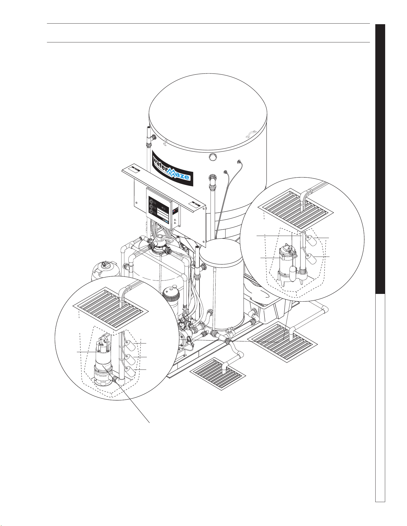
CL-304 INSTALLATION VIEW
89139720-9
CLARIFIER-304
VOLTAGE
SUMP PUMP
FILTER PUMP
TRANSFER PUMP
®
ON
PRENDER
OFF
I
O
ON
PRENDER
OFF
I
O
ON
PRENDER
OFF
I
O
OPERATING INSTRUCTIONS
INSTRUCCIONES DE OPERACION
INSTRUCTIONS D' OPERATION
Assembled in USA
Contains components from one or
more of the following countries: United
States, Austria, Brazil, Canada, China,
England, France, Honduras, Italy,
Japan, Mexico, Romania, Taiwan,
Thailand, Vie tnam.
INTENDED FOR INDOOR USE
Sump Pump
Installation
(Single Phase)
Sump
Pump
Sump
Pit
FS1
FS2
FS7
Sump Pump
Installation
(3 Phase)
Sump
Pit
Inlet
Line
Sump
Pump
FS2
FS1
Sump Pump Not Supplied with Machine.
See Specification on Page 30.
WATERMAZE CL-304 • 8.913-972.0-A
OPERATOR’S MANUAL WATER TREATMENT SYSTEM
10
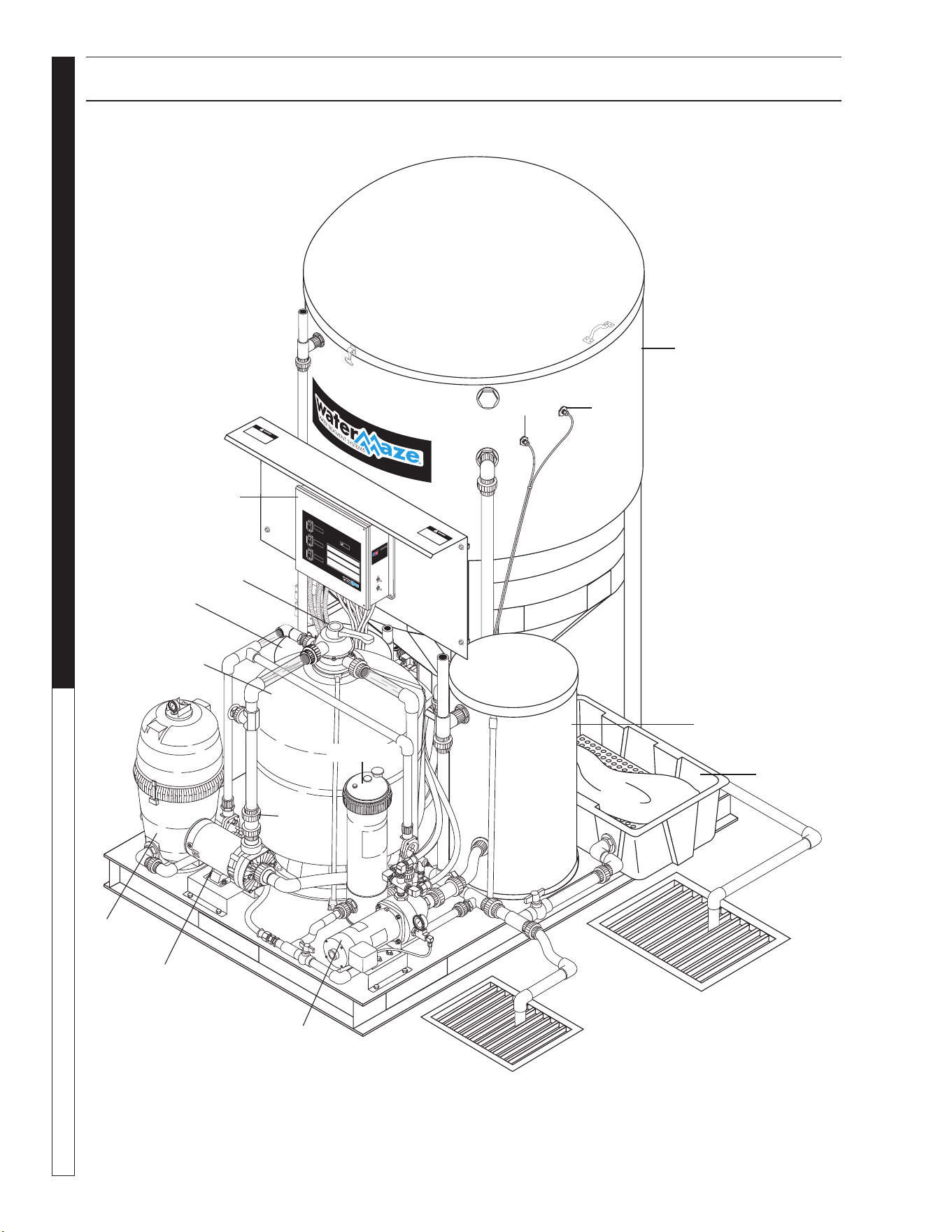
COMPONENT IDENTIFICATION
CLARIFIER-304
VOLTAGE
SUMP PUMP
FILTER PUMP
TRANSFER PUMP
®
ON
PRENDER
OFF
I
O
ON
PRENDER
OFF
I
O
ON
PRENDER
OFF
I
O
OPERATING INSTRUCTIONS
INSTRUCCIONES DE OPERACIO
N
INSTRUCTIONS D' OPERATION
Assembled in USA
Contains components from one or more of
the following countries: United States,
Austria, Brazil, Canada, China, England,
France, Honduras, Italy, Japan, Me xico,
Romania, Taiwan, Thailand, Vietnam.
INTENDED FOR INDOOR USE
89139720-10
Filter
Pump
Chlorinator
Valve 4
Cartridge
Filter
Transfer
Pump
Sludge
Tub
40 Gal.
Tank
300 Gal.
Tank
FS4 FS3
Electrical
Control Panel
Multi-Media
Filter
Valve 5
26 Gal.
Tank

WATERMAZE CL-304 • 8.913-972.0-A
11
WATER TREATMENT SYSTEM
OPERATOR’S MANUAL
OPERATING INSTRUCTIONS
▼ The 1/3 HP sump pump pushes the water from the
sump and sends it to the CL-304.
▼ The solids settle in the bottom of the 300 gallon
cone tank.
▼ The oil and grease are separated out by the co-
alescing cones.
▼ The skimmer removes the oil and sends it to the
oil decanter barrel. This is a routine maintenance
item that must be done manually.
▼ Processed water runs from the sump to the filter
pack and then to the 40 gal. storage tank.
▼ With use of a filter timer, water can be circulated
from the 300 gal tank through a chlorinator and
back to the pit for bacteria control.
FLOAT LEVEL CONTROLS
▼ The High Level Control Float #1 (normally open) is
the upper float which controls the upper limits of the
sump. It prevents the sump from flooding by open-
ing SV1, the rain water solenoid valve. The fresh
water makeup float #2 (normally closed) controls
the lower limits of the sump. It prevents the sump
from running dry by opening SV2, the fresh water
solenoid valve.
▼ Float tether length must be a minimum of 2" long.
▼ Turn-on point for the Fresh Water Make-up Float
must be at least 2" above the suction line intake.
The further the water must travel before reaching
the sump, the higher the float must be placed above
the suction intake.
▼ Floats must travel their complete arc without:
Water going over the top of the pit.
Floats touching sidewalls or bottom.
The pit running out of water.
Floats interfering with electrical wiring, plumb-
ing, bottom or sidewalls of sump, on any object.
Attach the floats to the PVC line on the sump
pump. Check to assure the floats can operate
freely.
Float Override Switch:
The Float Override Switches are located on the elec-
trical control panel. One switch turns “ON” the sump
pump, the other turns “ON” the filter pump. These
switches will cause the pumps to run until they are
turned “OFF”.
The Float Override Switches must be in the “OFF”
position for automatic operations.
VALVE LOCATION
AND FUNCTION
It is extremely important to know the location and func-
tion of the valves on the CL-304. Improper positioning of
the valves can cause overflow or damage which could
result in time consuming clean-up and repairs. Study
the section on “Valve Location and Function.”
Valve 1 -- Flow Control Valve
This valve controls the amount of water allowed into the
CL-304 from the sump pump.
Valve 2 -- Sludge Drain Valve
This valve should only be opened when draining
sludge.
Valve 3 -- Oil Skimming Bucket
This valve should be closed except when draining off
oil.
Valve 4 -- Filter Pack Flow Control Valve
This valve controls the amount of water allowed to flow
through the filter pack.
Valve 5 -- Filter Control Valve
When set on Filter, this valve allows water to pass
through the filter. When set on Backwash, the water
passes through the filter in reverse, then passes back
to the collection pit.
Valve 6-- Transfer Pump Valve
This valve is used to shut off the water supply to the
transfer pump for maintenance.
Valve 7-- Fresh Water Makeup Valve
This valve is used to control the volume of water allowed
into the machine when fresh water is called for.
Valve 8 -- Rain Water Overflow Valve
This valve is left open partially. When SV1 opens, some
water is allowed to discharge while still providing water
for the pressure washer.
Valve 9-- Outlet to Pressure Washer Valve
After start-up, this valve is left open all of the time. It
controls water to the pressure washer.
Valve 10 -- Rinse Water Control Valve
This valve is opened only when rinse water is needed.
Valve 11-- Drain Valve
This valve is used to drain the cartridge filter for main-
tenance.
WATERMAZE CL-304 • 8.913-972.0-A
OPERATOR’S MANUAL WATER TREATMENT SYSTEM
12
OPERATING INSTRUCTIONS
Valve 12 -- Recycle Flow Control Valve
This valve is used to control the volume of water go-
ing back to the collection pit for recycling through the
system when the timer activates the solenoid, SV3, for
recycling the system.
FILLING SYSTEM
WITH WATER
Valve 1 -- Open Valve 5 -- Filter
Valve 4 -- Open
On initial start-up, or if the system has been drained of
water, it will be necessary to fill the system and piping
with fresh water. This is done as follows:
Open valves 1, 4, and filter for valve 5.
Make sure the sump is full of water. Adjust the valve
positions as noted above. Turn “ON” the pump to allow
water to fill the sytem. You may have to turn the Sump
Pump Float Override Switch to the “ON” position to
start the pump. When the sytem is filled, turn “OFF”
the Float Override Switch. You may have to turn the
pump switch “OFF” to stop the pump.The float controls
will automatically fill the filter pac.
Running
Valve 1 -- Open Valve 9 -- Open
Valve 4 -- Open Valve 5 -- Filter
Adjust valves as shown above. When water begins to
flow through the CL-304, adjust Valve 1 so that the
flow meter reads 5 GPM. Record the flow rate in the
operation log. The CL-304 is now operational. Adjust
valve #4 to read 5 GPM.
Backwash Multi-Media Filter
Valve 1 -- Open Valve 9 -- Open
Valve 4 -- Open Valve 5 -- Backwash
Position valves for backwash as shown above. Turn the
filter pump float override switch to the “ON” position to
start pump. Adjust flow to 30 GPM using valve 4.
The water is now flowing in reverse through the Multi-
Media Filter taking all the impurities back to the pit. Turn
the Float Override to the “OFF” position. Return to the
filtering mode. Make sure the Float Override Switch is
in the “OFF” position for automatic operation.
ELECTRICAL
The machine, when installed, must be electrically
grounded in accordance with local and/or national
codes. Check for proper electrical supply. It is recom-
mended that a Ground Fault Circuit Interrupter be
installed in the circuit breaker for all WATER MAZE
Equipment. The floats in the sump run on 24 volts. For
the CL-304 check the serial plate for voltage require-
ments and amp loads.
NOTE: Always test all electrical power supplies for
proper voltage before wiring into any equipment. Always
verify voltage and amperage requirements on the serial
plate before testing electrical supplies.
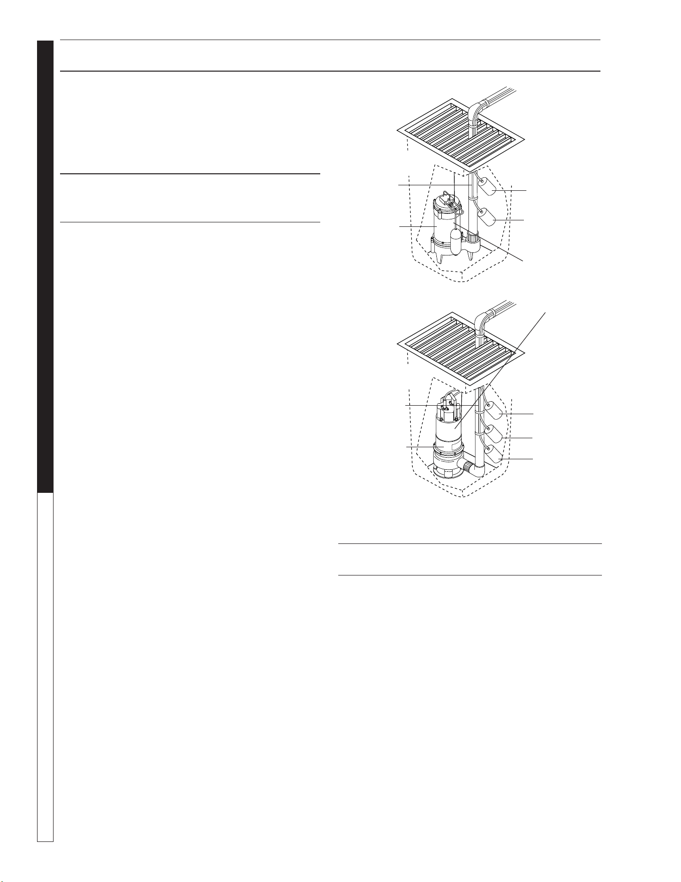
Sump Pump
Installation
(Single Phase)
FS2
Sump
Pump
Inlet
Line
FS1
Sump
Pit
Sump Pump
Installation
(3 Phase)
FS2
Sump
Pump
Inlet
Line
FS1
Sump
Pit
FS7
Sump Pump Not
Supplied with
Machine. See
Specification on
Page 32.

WATERMAZE CL-304 • 8.913-972.0-A
13
WATER TREATMENT SYSTEM
OPERATOR’S MANUAL
START-UP INSTRUCTIONS
GENERAL MAINTENANCE
AND SERVICE
Periodic Maintenance:
1. Turn “ON” the Sump Pump Float Override Switch.
The water level in the 300 gal. tank will rise. Con-
tinue until the level is high enough for the oil skim-
mer to begin skimming. Turn “OFF” the override
switch when all of the oil has been skimmed off.
2. Monitor the level of oil in the collection drum. Empty
as required.
3. Settled solids are collected in the bottom of the cone
of the CL-304 tank. The solids must be removed
periodically as dictated by the dirt load coming into
the machine. The procedure for removal is as fol-
lows:
Open Valve #2. Fill up the bag, then shut the valve.
Repeat as needed.
4. Check the electrical cords to ensure they are safe,
with no damage or cracking.
5. Check inlet and outlet pipes for leaks or damage.
Cartridge Filter:
The WATER MAZE cartridge filter is a high performance
industrial filter, manufactured from durable, corrosion-
proof materials. It is designed for continuous or intermit-
tent operation. The cartridge filter utilizes a reusable,
reinforced polyester filter cartridge element to provide
a high degree of water clarity and long filter cycles with
absolute minimum care.
Filtering:
Filtration starts as soon as flow is steady through the
filter. As the filter cartridge removes dirt from the water,
the accumulated dirt causes a resistance to flow. As a
result, pressure will rise and flow will decrease. When
the pressure rises 8 - 10 psi above the starting pres-
sure, or when flow decreases below the desired rate,
clean or replace the filter cartridges.
Remove/Replace Cartridges:
Removing Cartridge Elements
1. Shut off the pump.
2. Open the drain valve and allow the water to drain
from the filter. NOTE: To assist the draining process,
open the air vent a few turns.
3. Disassembly:
a. Unscrew the lock-ring from the top of the filter
and lift off.
b. To remove filter cover, tap it on the side to break
the seal.
CHECK LIST
BEFORE STARTING
1. Is inlet line connected from the sump
pump to the inlet of the CL-304?
2. Is the voltage correct?
3. Is the recycle line connected?
4. Is the Fresh Water Make-up hose
connected?
5. Are the floats adjusted correctly?
6. Is the chlorinator filled with
3" pucks?
START-UP
▼ Make sure that the CL-304 is level.
▼ Turn “ON” the Fresh Water Make-up hose.
▼ Fill the sump and 300 gal. tank with water.
▼ Turn the sump pump switch on the electrical control
panel to the “ON” position.
▼ Adjust the flow of water into the CL-304 using valve
#1 to 5 GPM . The water level should be between
5" and 8" below the top rim.
▼ Adjust the length of the High Level Control and the
Fresh Water Make-up Floats in the sump.
▼ Turn “ON” the filter timer inside the control panel by
pulling out the pins and rotating the pins to line up
with the arrow. This will ensure the water recycles
from the 300 gal. tank back to the collection pit.
Each pin pulled out will activate the solenoid valve
for one half hour.
▼ Look over the entire machine for leaks. The machine
was hydrostatically tested at the factory but may
have been damaged in shipment.
▼ Set the chlorinator on its lowest setting to begin
with. Adjust as needed.
START-UP CHECK LIST:
1. Sump Pump Override working?
2. Water in CL-304 level?
3. Fresh Water Make-up working? (#2)
4. Recycle System working?
5.
High Level Control Float working? (#1)
6. Filter Pump Override working?
YES NO
____ ____
____ ____
____ ____
____ ____
____ ____
____ ____
YES NO
____ ____
____ ____
____ ____
____ ____
____ ____
____ ____

WATERMAZE CL-304 • 8.913-972.0-A
OPERATOR’S MANUAL WATER TREATMENT SYSTEM
14
START-UP INSTRUCTIONS
4. To Remove Cartridge Element
a. Lift element out of cartridge tank with a slight
rocking motion.
c. Clean cartridge (see section on Cleaning
Cartridges).
Reinstalling Cartridges
1. Flush and drain any dirt or debris from the bottom
of the filter tank.
2. Replace the element into the tank housing, making
sure the air bleed hose is visible.
3. Make sure the filter cover flange sealing surface is
clean and the O-ring is in place. NOTE: The O-ring
will need to be lubricated periodically.
4. Replace the filter cover, making sure it is fully
seated.
5. Replace the loc-ring and secure hand tight.
6. Close the drain valve, set valves and follow instruc-
tions for “Filling System with Water”.
Cleaning Cartridges:
The cartridge filter element can be cleaned by pres-
sure washing inside and out with no more than 1000
psi of pressure, or use a garden hose. After hosing
the cartridge, for best results, allow the cartridge to dry
and carefully brush pleated surface areas to remove
fine particles.
A spare “standby” cartridge filter element is an excel-
lent investment. It provides convenience and assures
that your filter will always be ready to operate at peak
efficiency. For best results, use only genuine WATER
MAZE cartridges in your filter.
Winterizing:
If a heated area is not provided in areas where sub-
freezing temperatures can be expected, the entire
machine must be drained.
CHEMICAL MAINTENANCE
PROGRAM
Owner Chemical Maintenance Program
to Maintain Recycled Water Quality:
Daily monitoring and adjustment of the CL-304 re-
cycled water chemistry is essential. If not monitored
and controlled, the recycled water will become chemi-
cally unbalanced resulting in a host of problems such
as algae and bacteria growth, obnoxious odors, and
iron discoloration. Ultimately it will be unfit for reuse
and must be disposed of.
The daily monitoring and adjustment maintenance
program presented herein will, if followed, provide
suitable recyclable wash water. The proper maintenance
of the water is not complicated and depends upon a few
basic principles which are:
1. Physical - effective filtration and recirculation of
the water
Effective recirculation of the water through the catch
basin, and the CL-304 is achieved only if the system is
utilized often (daily 6-8 hours or more) or if the system is
set to recirculate the water throughout the total system.
The CL-304 has the controls and procedures to achieve
continuous effective water recirculation throughout the
process. Therefore, if the CL-304 is operated properly, it
will achieve the required need of effective filtration and
recirculation.
2. Chemical - proper adjustment of alkalinity and
pH
The most important factor to control and maintain is
the pH of the water (i.e. the acidity or alkalinity). If the
recycled water is acidic (low pH) it will dissolve iron into
solution. The presence of iron of more than 0.2 ppm will
result in rusty staining of virtually anything the water
comes in contact with. Alkaline water can cause cloudi-
ness and greatly reduces the effectiveness of chlorina-
tion. Many of the cleaning detergents are alkaline and will
make the recycled water too alkaline. Also, high alkaline
water is difficult to filter and decreases filter media life.
The proper pH range to maintain is 6.8 - 7.2.
Alkalinity refers to the soluble salts in the water. These
include bicarbonates, carbonates, hydroxides and other
alkali compounds. The waters total alkalinity controls
its resistance (buffering ability) to large fluctuations in
pH levels.
Another factor which should be monitored for proper
water chemistry balancing, is calcium hardness. The
presence of too much calcium can lead to the formula-
tion of scale in the filters.
3. Biological - adequate disinfection, algae, bacte-
ria, and odor control
Chlorination is used to control bacteria, odor and algae
formation. For chlorine to be effective, it must be avail-
able as free chlorine. If the proper pH and alkalinity is
not maintained, or if the water contains dirt particles,
the chlorine becomes combined chlorine and will not
be effective in the control of algae and bacteria growth.
Combined chlorine has only 1/15th the strength of free
chlorine. Chlorine can be added by using a filter timer.
Inadequate or improper addition of chlorine could result
in algae and bacteria growth. Once algae and a bacte-
rial growth starts, the system must be shock treated. It
is best to minimize the chances of algae and bacteria
problem.

WATERMAZE CL-304 • 8.913-972.0-A
15
WATER TREATMENT SYSTEM
OPERATOR’S MANUAL
CHEMICAL MAINTENANCE PROGRAM
The killing of bacteria by chlorine exists in
two phases:
1. The penetration of the active germicidal principal
(hypochlorous acid) into the bacterial cell.
2. The chemical combination of this ingredient with
the protoplasm (the complex composition which
forms the essential part of plant and animal cells).
This combining is directly responsible for the death
of the organism.
The activity of this germicidal effect is reduced in al-
kaline solutions (those with a pH greater than 7.5) and
expressed as follows:
pH % of Effectiveness
4.0 100.0
5.0 99.6
6.0 95.8
7.0 69.7
8.0 18.7
9.0 2.2
10.0 0.2
Hypochlorite when added to solutions with a pH lower
than 6.0 can produce oxide which is toxic. In vehicle
washing, almost all cleaning compounds are alkaline
in nature. Hypochlorite will still control bacterial growth
and thus smell at higher alkaline ranges, but as the
table indicates, its effectiveness is reduced.
To compensate for this inhibited activity, a larger quan-
tity of hypochlorite is used. This will control bacterial
growth but will increase operational costs.
Typical hypochlorite has a pH of approximately 11.6.
This high pH will only increase the pH of holding tank
water making pH adjustment more difficult.
Trichloro-S-Triazine Trione is a chlorine compound
which has a pH of 3.0 and when added to holding tanks
will aid in the reduction of tank pH levels.
Unlike hypochlorite, which is usually 15 percent chlorine
and will produce sodium or calcium salts in holding
tanks, these new products are 99 percent chlorine
which means that if a solid “puck” of chlorine is used,
the total effectiveness of the puck is superior to that of
hypochlorite and no negative by-products are produced.
DAILY CHEMICAL
MAINTENANCE
Step 1. Collect a water sample from the 40 gal. tank.
NOTE: Be sure water is circulating from sump through
the CL-304 system and back to the catch basin.
Step 2. Using the test strips supplied, measure:
A. The pH.
B. The total chlorine (if using chlorine).
C. The free chlorine (if using chlorine).
D. The alkalinity (if needed).
E. The calcium hardness (if needed).
Step 3. If the pH is 6.8-7.2 go to Step 4, if not, adjust
the pH in the water being recycled between the oil
water separator and the pit to pH 6.8-7.2. Muriatic acid
or liquid alum can be used to lower the pH. Soda ash
(sodium carbonate) or caustic soda (sodium hydroxide)
can be used to raise the pH.
Adjust the pH gradually allowing complete mixing
after adding chemical. Take a new sample, read the
pH and continue to adjust gradually until the desired
pH is achieved.
Step 4. The total alkalinity should be between 50-
150 ppm. If the total alkalinity is too low add sodium
bicarbonate to raise it. If total alkalinity is too high, add
muriatic acid to bring it within acceptable range. This
will also decrease the pH. If the pH goes below 7.0, add
sodium bicarbonate to increase the pH. This procedure
may have to be repeated several times to get the pH
and total alkalinity into the proper range.
Step 5. The calcium hardness should not exceed 25
grains. If it is too high, some water must be removed
from the system and fresh makeup water added. Alter-
natively, an ion exchange water softener or an ionizer
may have to be added to the system to reduce and
maintain lower calcium hardness levels.
Step 6. Free chlorine levels should be 1-2 ppm if chlo-
rine is added for additional control. A 10-15% concen-
trated liquid chlorine is available at pool supply outlets.
Household bleach can be used, but contains only 5%
chlorine. Chlorine continually dissipates and becomes
used up and the chlorine level must be adjusted daily.
Remember chlorine is most effective when the pH level
is correct (6.8-7.2).
Initially, in order to achieve proper water chemistry bal-
ance, extra time is needed. However, once achieved,
it can be easily maintained in a minimum amount of
time by daily monitoring and adjustment.
PUMP OPERATION
(Filter or Transfer)
WARNING: Do not touch pumps, pump motors,
water or discharge piping when the pumps are con-
nected to electrical power. Do not handle a pump
or pump motor with wet hands or when standing
on a wet or damp surface or in water. Never touch
a pump or discharge piping when a machine is
operating or fails to operate. Always disconnect
the pump cord (power) before handling.
WATERMAZE CL-304 • 8.913-972.0-A
OPERATOR’S MANUAL WATER TREATMENT SYSTEM
16
PUMP MAINTENANCE AND PRESSURE SWITCH OPERATION
1. The shaft seal depends on water for lubrication.
Do not operate the pump unless there is water. Dry
running (pump not pumping water) will cause seal
damage and eventual pump failure.
2. The motor is equipped with an automatic reset
thermal protector. This means if the temperature in
the motor should rise unduly, the switch will cut off
all power before damage can be done to the motor.
When the motor has cooled sufficiently, the switch
will reset automatically and restart the motor. If the
protector trips repeatedly (cycling on protector)
the pump should be removed and checked for the
cause of the difficulty. Low voltage, long extension
cords, clogged impeller, very low head or lift, etc.,
could cause cycling. Cycling of the protector will
cause eventual motor burnout.
PUMP MAINTENANCE
(Sump)
WARNING: Before attempting
to service, disconnect power
from machine. Do not handle
the pump with wet hands or
when standing on a wet or damp
surface or in water. Failure to
follow precautions can result in
personal injury and /or property
damage.
NOTE: Only qualified electricians or servicemen should
attempt to repair this machine. Improper repair and/or
assembly can cause an electrical shock hazard.
1. Bearings in this machine are pre-lubricated. No
additional lubrication is necessary.
2. Cleaning - Occasionally clean the sump pit and pump
if dirt or foreign matter accumulate. Small stones,
gravel, sand, dirt, silt, etc. can clog and damage
the pump and pump seal, eventually causing pump
failure.
3. Disassembly of the motor prior to expiration of the
warranty will void the warranty. It may also cause
internal leakage and damage to the machine. If
repairs are required, return the pump to a local
service station.
4. If the motor has been disassembled or the switch
chamber opened after the warranty expiration date,
the O-rings and gaskets must be replaced. Care
must be taken to assure that the seals, the switch
cover and air tube gaskets do not leak.
5.
The pump should be checked for proper operation
weekly or monthly by watching operation of pump.
If anything has changed since pump was new, the
pump should be examined, and repaired if necessary.
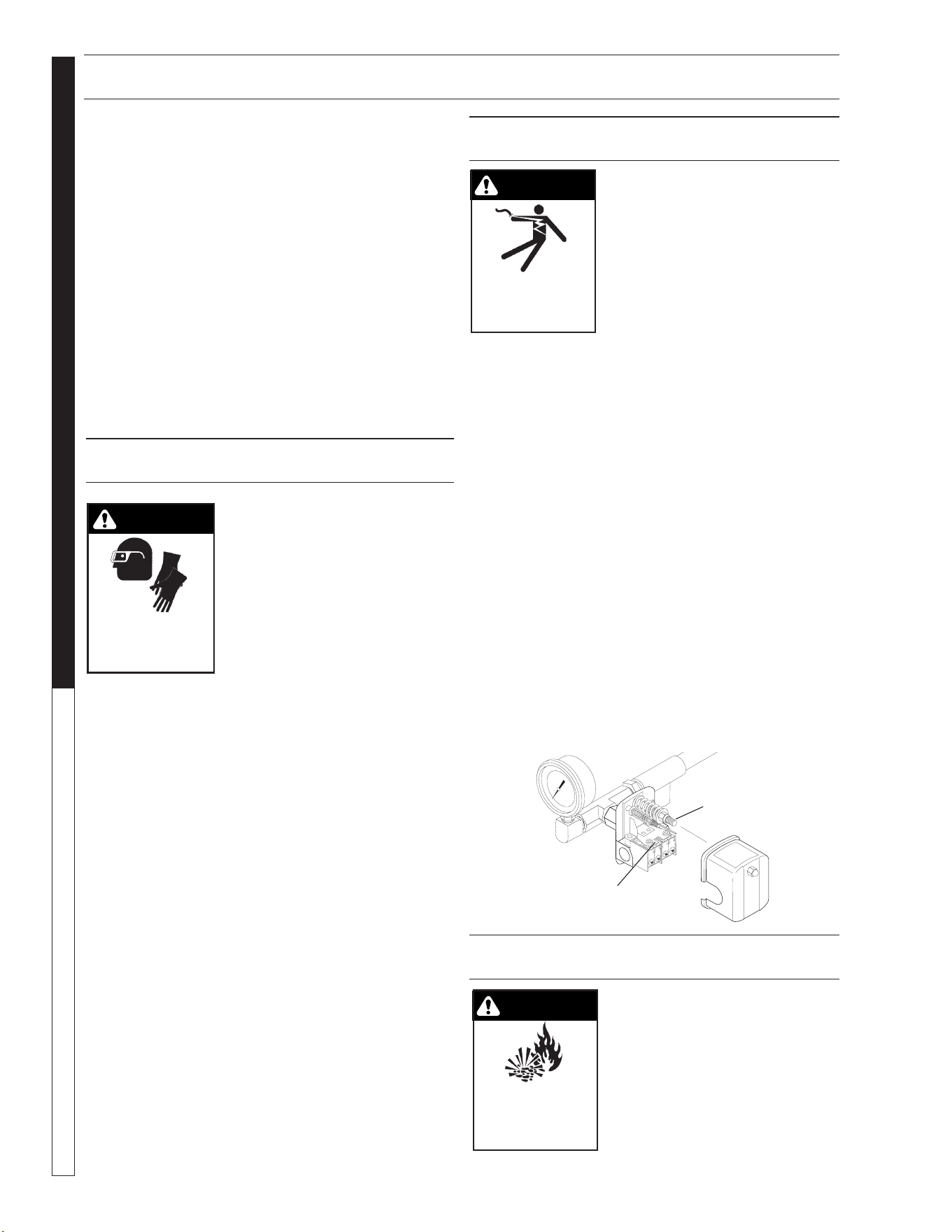
PRESSURE SWITCH OPERATION
WARNING: Live electrical con-
tacts are exposed, so disconnect
power first and have work per-
formed by a qualified electrician.
Remove cover of the pump pres-
sure control switch to allow access
to the two nuts used to adjust the
pump operating pressure. The
pressure switch on Water Maze
equipment is set at the factory and should not have to
be adjusted at start-up, but will need to be verified at
start up and maintained regularly at least monthly.
1. The nut on the larger spring in the pump pressure
switch, adjusts the pump cut in (cut on) and pump
cut out (cut off) pressures simultaneously.
2. The nut atop the smaller spring in the pump pres-
sure switch only controls the cut out range and is
used to narrow or widen the gap between the pump
cut in and cut out pressures.
3. To cycle the pump less frequently, the gap should be
as wide as possible while still allowing the pump to
shut off quickly when all outlets are closed. Adjust
the smaller spring to widen the gap between pump
in and out (on and off). 40-45 PSI (CLP, Rec2-20)
or 30 PSI (EC1-300A) is desirable. Adjusting the
larger spring should not be necessary.
4. When making pressure switch adjustments, make
sure all pump outlets are off or closed, except for
the one outlet valve used to relieve and build pres-
sure while making pressure switch adjustments.
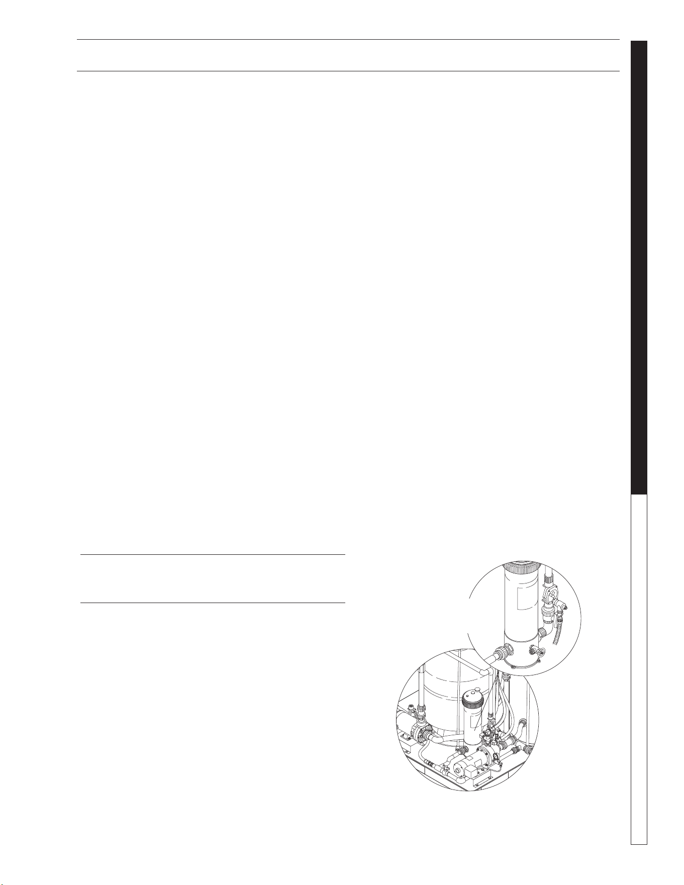
PRESSURE TANK OPERATION
WARNING! When the tank has
been in service and a change to
a higher pre-charge pressure is
necessary because of a required
change in the pressure switch
setting, failure to follow instruc-
tions below can cause a rupture
or explosion and could cause
serious or fatal personal injury
and/or property damage.
WARNING
PROTECTIVE
EYEWEAR AND
CLOTHING MUST
BE WORN.
WARNING
RISK OF
EXPLOSION:
FOLLOW
INSTRUCTIONS
WHEN CHANGING
PRESSURE
WARNING
RISK OF
ELECTRIC SHOCK:
USE CAUTION
WHEN HANDLING.
89139720-16
Controls
Cut In/Cut Out
Controls
Cut Out Range
WATERMAZE CL-304 • 8.913-972.0-A
17
WATER TREATMENT SYSTEM
OPERATOR’S MANUAL
89139720-11
PRESSURE TANK OPERATION AND CHLORINE DISPENSER
• Do not adjust or add pressure if there has been a
loss of air.
• Do not adjust the pre-charge pressure if there is
visible exterior corrosion.
• Do not adjust the pre-charge pressure if there has
been a reduction of the pump cycle time or the pre-
charge pressure compared to its initial setting. A
reduction in pump cycle time can result from loss
of tank corrosion and any re-pressurization or addi-
tional pressure could result in rupture or explosion.
• Pressure tank pressure is factory set but will have
to be checked regularly (at least monthly). Use an
air pressure (tire) gauge. Before checking air pres-
sure on the pressure tank, purge all water out of
the tank by turning the pump on and pumping all
water out of the pressure tank.
1. Our transfer pump water systems use a water pres-
sure tank and water pump with these two pressure
operation ranges:
Cut in (start pumping): 20 PSI
Cut out (stop pumping): 30 PSI (EC1-300A)
Cut out (stop pumping): 40-45 PSI (CLP, REC2-20)
2. Typical factory set air pressure on bladder-type
residential water pressure tanks are shipped from
the factory with a standard pre-charge of:
18 psig for models WX-101 and WX-102
18 psig for models WX-103 and WX-203
18 psig for models WX-205 and WX-350
3. Set the well tank air pressure to 2 PSI below the
pump pressure switch cut-in pressure. This is usu-
ally 18 PSI.
AUTOMATIC CHLORINE
DISPENSER #8.723-207.0
Your WATER MAZE HC3315 series chlorinator is
designed for maintaining the proper chlorine level in
your waste water. Your HC3315 holds up to 15 lbs. Use
only Trichloro-S-Triazinetrione tablets in this dispenser.
Under normal conditions, nine tablets should provide a
minimum of one to two weeks worth of chlorine.
Exercise EXTREME CAUTION when opening or servic-
ing your dispenser. Always shut off pump and available
valves before opening. Do not inhale fumes from any
chemical feeder or container. Protect your eyes, skin
and clothing from chemicals at all times. Safety glasses,
gloves and protective clothing should be worn when
operating or servicing your dispenser. Chemicals should
not be allowed on exposed skin surfaces.
NEVER open dispenser when pump is running.
Always read label and carefully follow manufacturer’s
and dealer’s recommendations for proper water condi-
tioning and requirements for your particular waste water.
Directions For Use.
Before start up of your chlorine dispenser, your water
should have a pH balance of approximately seven (7).
Follow dealer and chemical manufacturer’s directions
and instructions.
The chlorine demand for waste water varies based on
use, temperature, chemicals, etc. Using a 1,000 gallon
pit as a guide, we suggest you place about 7 lbs. of
large, slow dissolve chlorine tablets in your dispenser.
Check chlorine levels daily. Use the control dial to regu-
late the amount of chlorine being used.
Easy-Lok Cover
To Open
1. Shut off pump and any other in-line valves to pre-
vent back flow, if applicable. Wait one minute.
2. Turn cover cap counterclockwise to open. Caution:
Do not inhale fumes.
To Close
1. Press cover, with O-ring seal, firmly into body. En-
gage cover cap threads and turn clockwise.
2. Open in-line valves and restart pump.
Winterizing
Where freezing temperatures can be expected, drain
all water from feeder. Carefully remove undissolved
tablets and rinse out dispenser thoroughly with water.
Replace cover.
Pressure
Tank/
Valve
WATERMAZE CL-304 • 8.913-972.0-A
OPERATOR’S MANUAL WATER TREATMENT SYSTEM
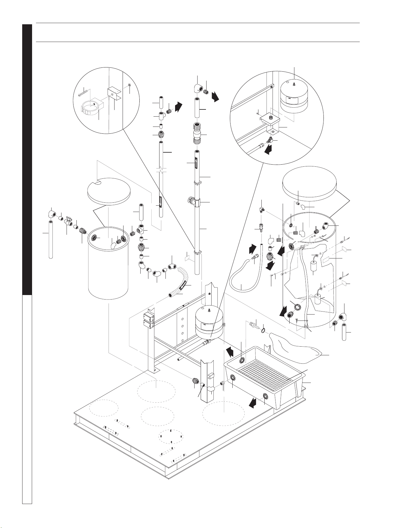
18
89139720-5
9
8
1
11
10
12
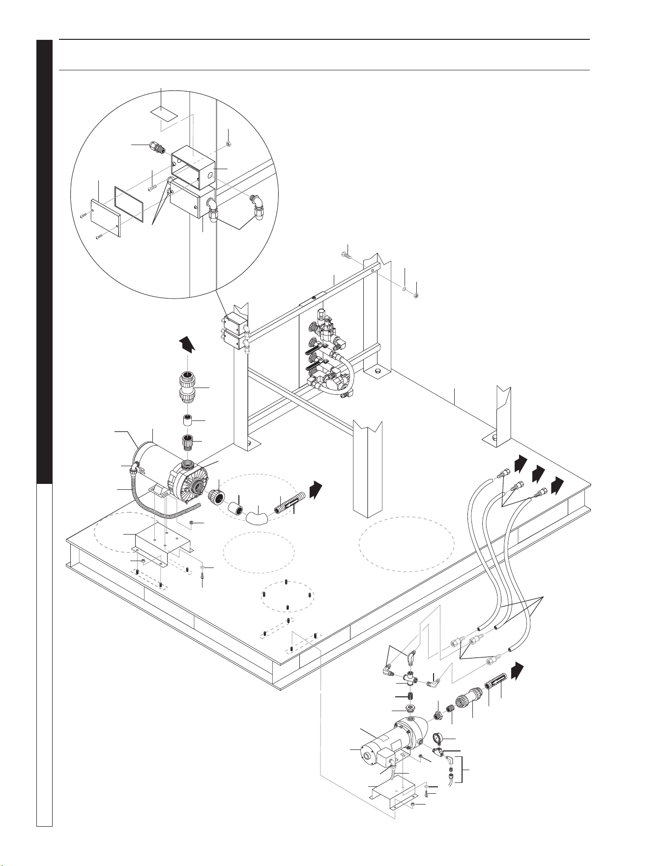
PUMP PLUMBING BREAKDOWN EXPLODED VIEW
Included
with Pump
Transfer
Pump
6
9
40
4
10
27
28
8
13
1
7
5
17
20
18
5
24
19
2
8
21
3
Filter
Pump
16
15
22
11
14
26
30
30
25
29
31
8
39
32
35
33
34
36
39
37
38
37
41
28
25
17
5
7
42
12
3
23

WATERMAZE CL-304 • 8.913-972.0-A
19
WATER TREATMENT SYSTEM
OPERATOR’S MANUAL
PUMP PLUMBING BREAKDOWN EXPLODED VIEW PARTS LIST
ITEM PART NO. DESCRIPTION QTY.
1 8.913-078.0 Base, Cl-304 Welded Assy 1
8.913-079.0 Base, CL-304 (SS Option) 1
2 8.711-812.0 Hose, 1", Gray Conduit 5"
3 8.706-367.0 Pipe, 1.5", Pvc 80 1.5 x 2-1/2
(Spacer) 2
4 8.706-800.0 Nipple, 3/4" Hex, Brass 1
5 9.802-788.0 Nut, 3/8 Whiz Loc Flange,
SS 10
6 9.802-721.0 Bolt, 3/8" x 1" HH/NC, 316
SS 2
7 9.802-808.0 Washer, 3/8", SAE, SS 6
8 9.802-517.0 Connector, 1/2" L/T, 90°,
Black 4
9 8.711-815.0 Hose, 1-1/2", Gray Conduit,
Per Foot 36"
10 8.706-374.0 Elbow, 1-1/2" S x S,
PVC 80, 90° 1
11 8.726-026.0 Motor, 3/4 HP, 230V 1
12 8.726-024.0 Pump, Wet End, 3/4 HP,
Center Discharge 1
13 9.802-805.0 Washer, 5/16", Flat,
SAE, SS 2
14 8.707-297.0 Valve, 1.5" PVC Ball Check 1
15 8.718-887.0 Nut, 5/16" Whiz Loc
Flange, SS 2
16 8.706-852.0 Cross, 3/4" Female Pipe 1
17 9.803-557.0 Elbow, 3/4" SAE x 3/4", 90°,
Brass 3
18 8.716-324.0 Box, Junction 4 Hole, 1/2" 1
19 8.716-321.0 Box, Junction 3 Hole, 1/2" 1
20 9.802-699.0 Screw, 10-32" X 3/4"
Slot Pan 4
21 9.802-696.0 Nut, 10/32" NF ST ST KEP 4
22 9.802-483.0 Cover, Metal, 2" x 4",
Weather-Proof 2
23 8.913-097.0 Rail, CL-304 Water Panel
Mount 2
PART NO. DESCRIPTION QTY.
24 8.706-929.0 Bushing, 1" x 3/4" Barstock 1
25 9.802-152.0 Swivel, 3/4" SAE Fem,
Push-On 6
26 9.802-732.0 Bolt, 3/8" x 2-1/2", GR 5, SS 4
27 9.802-261.0 Hose, 3/4" Push-On,
3/4" x 76" 3
28 8.900-474.0 Label, Flow Arrow 2
29 9.802-780.0 Nut, 3/8" Stainless,
ESNA, NC 4
30 9.802-514.0 Strain Relief, LT, STR, 1/2 3
31 8.940-186.0 Label, Float Switch
Junction Box 1
32 8.707-300.0 Valve, 1" PVC Ball Check 1
33 8.706-439.0 Nipple, 1", PVC 80, Close 1
34 8.715-382.0 Pump, 1/2 HP, 115/230V
5 Cyclone 1
35 8.712-154.0 Gauge, Pressure 0-100 1/4" 1
36 8.706-858.0 Tee, 1/4" Street 1
37 8.913-334.0 Pump Rail, Delta 500 2
38 8.706-405.0 Bushing, 1-1/4"x 1" MT x FT,
PVC 80" 1
39 9.802-448.0 Conduit,Wtr. Tight, Flex, 1/2"
( 1/2" x 10 Ft) 2
40 8.718-619.0 Bolt,
5/16" x 3/4 NC GR5, SS
2
41 8.750-270.0 Fitting, Compl-1/2" S x 1-1/2"
MBT, Blk 1
42 8.706-441.0 Adapter, 1-1/2" S x
1-1/2 MPT 1
WATERMAZE CL-304 • 8.913-972.0-A
OPERATOR’S MANUAL WATER TREATMENT SYSTEM
20
89139720-2
6
8
4
5
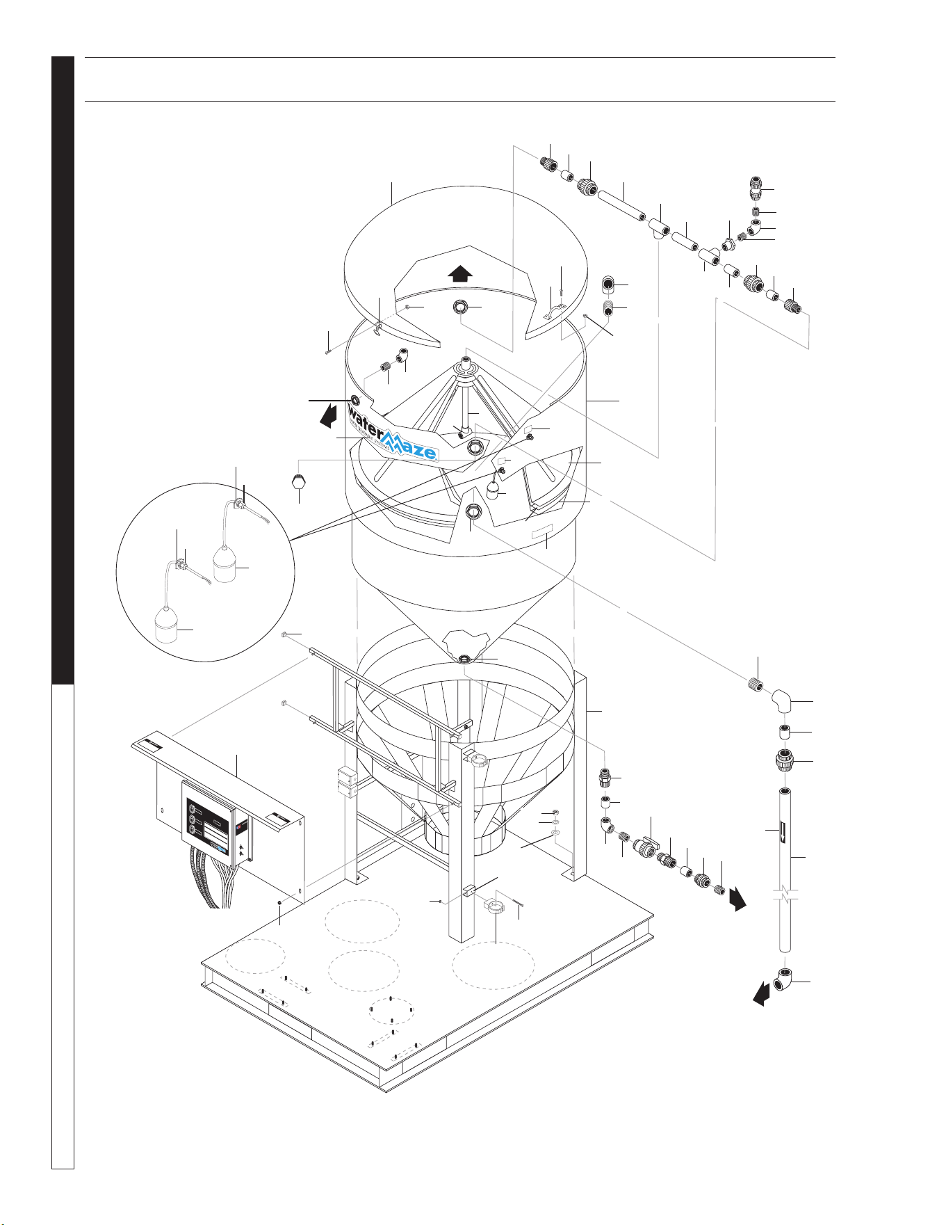
CONE ASSEMBLY EXPLODED VIEW
4
10
4
12
27
28
8
13
1
7
4
8
5
17
18
5
24
2
8
21
3
42
16
15
23
11
14
6
26
31
30
31
25
20
25
29
31
33
30
32
35
33
34
36
39
37
38
40
43
41
42
44
47
45
46
48
51
49
50
52
55
53
54
56
7
3
2
42
49
25
2
28
19
38
9
22

WATERMAZE CL-304 • 8.913-972.0-A
21
WATER TREATMENT SYSTEM
OPERATOR’S MANUAL
CONE ASSEMBLY EXPLODED VIEW PARTS LIST
ITEM PART NO. DESCRIPTION QTY
1 8.706-367.0 Pipe, 1.5", PVC 80 12 "
2 8.706-426.0 Tee, 1.5" S x S x S, PVC 80 3
3 8.750-743.0 Bulkhead, 1/2" Polypro 2
4 8.706-490.0 Bulkhead, 1-1/2" Polypro 4
5 8.716-142.0 Swtch, Float, N/O 1
6 8.716-145.0 Switch, Float, N/C 1
7 9.802-514.0 Strain Relief, LT, STR,
1/2" NPT, .23-.45D 2
8 8.706-372.0 Elbow, 1-1/2" S x T,
PVC 80, 90° 3
9 8.719-180.0 Tank, 300 Gal Clarifier,
w/o Lid 1
10 8.719-181.0 Cone, CLP5000 Sup Colescn,
w/Hole/Slot/Lip 1
11 8.719-182.0 Lid, 300 Gal Clarifier Tank 1
12 8.719-184.0 Cone, CLP5000 Coalescing,
w/ Hole, No Slot 1
13 8.913-083.0 Spacer, Pipe Clips, Clarifier 2
14 8.913-138.0 Stand, Tank, CLP5000,
Low Profile 1
15 8.913-141.0 Panel, Control Mount 1
16 8.707-298.0 Valve, Ball Check 1/2" PV 1
17 8.706-648.0 Handle, Sandpot Lid 1
18 8.707-349.0 Valve, 2" Single Union Ball 1
19 8.706-476.0 Union, 2" FS x FT, PVC 80
Spears 1
20 8.719-183.0 Cone, CLP5000 Coalescing,
w/Hole, w/Slot 1
21 8.706-421.0 Hanger, Pipe, 1-1/2"
Click #47 2
22 9.802-781.0 Nut, 3/8" NC, Whiz Loc
Flange 4
23 9.803-674.0 Screw, 8/32" x 2" Hanger,
Pipe 2
24 9.802-785.0 Nut, 8/32", Keps 2
25 8.706-469.0 Union,1-1/2" Slip x Slip,
PVC 80 Spear 3
26 8.706-394.0 Plug, 1-1/2", PVC 80 1
27 9.802-747.0 Screw, 6/32" x 5/8", RND, HB,
MCH 12
28 8.706-451.0 Adapter, 2" Slip x MT,
PVC 80 2
29 8.706-384.0 Elbow, 2" Slip x FPT, PVC 80 1
30 8.706-583.0 Pipe, 2", Gray, PVC 80,
2" x 2-3/4" (Spacer) 2
31 8.706-424.0 Nipple, 1.5" x Close, PVC 80 3
32 8.706-406.0 Bushing 1-1/2" x 1/2" SPGX FT,
PVC 80 Spears 1
ITEM PART NO. DESCRIPTION QTY
33 8.706-467.0 Nipple, 1/2", PVC 80, Close 2
34 8.706-479.0 Bulkhead, 2" NPT, Polypro 1
35 8.718-893.0 Nut, 1/2" SS 304, Hex, NC 4
36 8.719-021.0 Washer, 1/2" Lock, SS 4
37 8.718-997.0 Washer, 5/8" Flat SAE, SS 4
38 8.706-466.0 Nipple, 2" Close, PVC 80 2
39 8.706-367.0 Pipe, 1.5", PVC 80 15 "
40 8.706-367.0 Pipe, 1.5", PVC 80 8 "
41 8.706-367.0 Pipe, 1.5", PVC 80 52 "
42 8.706-367.0 Pipe, PVC 80, 1.5" x 2.5"
(Spacer) 3
43 8.706-367.0 Pipe, 1.5", PVC 80 4 "
44 9.802-696.0 Nut, 10/32" NF ST ST Kep 4
45 9.802-699.0 Screw, 10/32 x 3/4",
Phil Pan, SS 4
46 8.706-568.0 Handle, Rubber T, w/Keeper 3
47 8.718-854.0 Nut, 6/32, Keps, SS 12
48 8.706-370.0 Elbow, 1/2" FIPT x FIPT,
PVC 80, 90° 1
49 8.706-441.0 Adapter, 1.5" Slip x MT,
PVC 80" 2
50 8.706-374.0 Elbow, 1-1/2" S x S,
PVC 80, 90° 1
51 8.900-529.0 Label, Tank 1, Clar., Lexan 1
52 8.900-803.0 Label, Water Maze,
Logo Small 1
53 8.900-525.0 Label, FS3 N/C, Clar, Lexan 1
54 8.900-527.0 Label, FS4 N/O, Clar, Lexan 1
55 8.706-592.0 Cap, 1.25" Square, 4
56 8.900-474.0 Label, Flow Arrow 1
WATERMAZE CL-304 • 8.913-972.0-A
OPERATOR’S MANUAL WATER TREATMENT SYSTEM
22
8913972-3
4
13
3
5
2
9
7
6
11
HOLDING TANK EXPLODED VIEW
30
3
12
4
3
9
12
27
28
8
13
1
7
10
5
17
20
18
21
5
24
19
2
8
3
23
16
14
23
22
11
14
6
26
29
30
23
25
30
28
32
35
33
34
36
39
37
38
40
43
41
42
49
45
48
17
47
54
50
53
51
52
59
55
58
56
57
60
63
61
62
15
48
28
3
10
28
54
28
28
52
48
28
12
8
3
27
28
10
10
8
3
37
15
10
38
46
44
31
WATERMAZE CL-304 • 8.913-972.0-A
23
WATER TREATMENT SYSTEM
OPERATOR’S MANUAL
HOLDING TANK EXPLODED VIEW PARTS LIST
ITEM PART NO. DESCRIPTION QTY.
1 8.706-421.0 Hanger, Pipe, 1-1/2" Click 2
2 8.706-366.0 Pipe, 1", PVC 80 5"
3 8.706-424.0 Nipple, 1.5" x Close, PVC 80 6
4 8.706-367.0 Pipe, 1.5", PVC 80 14"
5 8.706-367.0 Pipe, 1.5", PVC 80 (1.5"x 8") 2
6 8.706-367.0 Pipe, 1.5", PVC 80 52"
7 8.707-299.0 Valve,
1.5" Swing Check PVC
1
8 8.706-372.0 Elbow, 1-1/2 S x T,
PVC 80, 90° 4
9 8.706-441.0 Adapter, 1.5 Slip x MT,
PVC 80 1
10 8.706-490.0 Bulkhead, 1-1/2" Polypro 5
11 8.706-367.0 Pipe, 1.5", PVC 80 12"
12 8.706-469.0 Union,1-1/2" Slip x Slip,
PVC 80 3
13 8.707-344.0 Valve, PVC 1.5" Slip x Slip,
Gate 1
14 9.803-557.0 Elbow, 3/4" SAE x 3/4",
90° Brass 2
15 9.802-152.0 Swivel, 3/4" SAE Fem,
Push-On 2
16 9.802-261.0 Hose, 3/4" Push-On, /Ft 65"
17 8.706-484.0 Bulkhead, 1", Polypro 2
18 8.711-815.0 Hose, 1-1/2", Gray Conduit 12"
19 8.706-409.0 Adapter, 1" MT x Slip,
PVC 80 1
20 8.706-597.0 Union, 1", S x S, PVC 80 1
21 8.706-367.0 Pipe, 1.5", PVC 80 16"
22 8.707-361.0 Valve, 1-1/2" S 80 PVC S x S
Molded In 1
23 8.706-378.0 Elbow, 1" Slip x FIPT,
PVC 80, 90° 3
24 8.706-367.0 Pipe, 1.5", PVC 80, /Ft 30"
25 8.719-176.0 Tank, 4.4 Gal Pre-pressurized,
Blue 1
26 8.706-377.0 Elbow, 3/4" FIPT x FIPT,
PVC 80, 90° 1
27 8.706-379.0 Elbow, 1-1/2" Slip x Slip,
PVC 80, 45° 2
28 8.706-367.0 Pipe, 1.5", PVC 80
1.5 x 2-1/2" (Spacer) 8
29 8.719-169.0 Tank, 26 Gal Black Vertical
Poly, w/ Lid 1
30 8.706-439.0 Nipple, 1", PVC 80, Close 3
31 8.719-185.0 Tank, 40 Gal Black Vertical
Poly, w/ Lid 1
32 8.719-191.0 Bag, Sludge, Biodegradable 5
ITEM PART NO. DESCRIPTION QTY.
33 8.706-453.0 Adapter, 2" MT x 2" M Hose
Insert 1
34 8.913-094.0 Support, CLP Sludge Bag 1
35 8.709-083.0
Clamp, Screw, 2-1/2-3-1/2" SS
1
36 8.706-366.0 Pipe, 1", PVC 80 1" x 2"
(Spacer) 1
37 9.802-514.0 Strain Relief, LT 1/2 2
38 8.750-743.0 Bulkhead, 1/2" Polypro 2
39 8.716-143.0 Switch, Float, N/C (Gray) 1
40 8.716-142.0 Swtch, Float, N/O, .20PM
(Black) 1
41 8.911-223.0 Mounting Tab, Filter 4
42 8.709-342.0 Strap, 84", Filter 2
43 9.802-799.0 Screw, #14 x 1", Tek, Blk.,
Zinc 2
44 8.718-753.0 Screw, 1/4"-20 x 3/4" Phil
PH SS M/S 4
45 8.718-568.0 Washer, 1/4" Flat SS
Sealing Rub 4
46 8.718-965.0 Washer, 1/4", SS, Flat 4
47 8.718-817.0 Nut, 1/4-20, Whiz Loc
Flange, SS 4
48 8.900-474.0 Label, Flow Arrow 3
49 8.900-530.0 Label, Tank 2, Clar., Lexan 1
50 8.706-479.0 Bulkhead, 2" NPT, Polypro 1
51 8.719-179.0 Tub, Black Sludge,
Rectangular w/Lid 1
52 8.706-374.0 Elbow, 1-1/2" S x S,
PVC 80, 90° 2
53 8.900-526.0 Label, FS5 N/C, Clar, Lexan 1
54 8.706-428.0 Tee,1-1/2" S x S x T
(Threaded Center Slip) 2
55 8.913-354.0 Bracket, Surge/Pressure
Tank, Deltas 1
56 8.900-528.0 Label, FS6 N/O, Clar, Lexan 1
57 8.913-083.0 Spacer, Pipe Clips, Clarifier 2
58 9.802-785.0 Nut, 8/32", Keps 2
59 9.803-674.0 Screw, 8/32" x 2",
SS Phil Ph 2
60 8.900-458.0 Label, Inlet 1
61 9.802-052.0 Bulkhead, 3/4" Polypro 1
62 8.706-369.0 Nipple, 3/4", PVC 80, Close 1
63 9.802-766.0 Screw, 3/8 x 1 HX Wash Head
Sheetmetal Zn 2
WATERMAZE CL-304 • 8.913-972.0-A
OPERATOR’S MANUAL WATER TREATMENT SYSTEM
24
C
A
R
T
R
I
D
G
E
F
I
L
T
E
R
89139720-1
2
7
3
1
M
U
L
T
I
-
M
E
D
I
A
F
I
L
T
E
R
FILTER TANK EXPLODED VIEW
47
6
12
4
27
28
13
1
7
40
10
5
17
20
18
21
5
19
19
2
8
21
3
23
16
15
15
22
11
14
26
29
31
30
33
23
20
32
35
33
36
39
37
38
40
41
42
45
48
47
52
51
53
54
50
55
56
21
59
22
17
20
22
20
19
22
55
55
55
55
55
50
55
22
22
52
58
40
40
40
40
48
48
48
45
49
46
25
21
22
53
19
13
56
56
22
17
35
36
40
13
15
55 44
55
7
17
40
17
22
43
K Included with
Chlorinator
K
K
K
9
24
57
19

WATERMAZE CL-304 • 8.913-972.0-A
25
WATER TREATMENT SYSTEM
OPERATOR’S MANUAL
ITEM PART NO. DESCRIPTION QTY.
1 8.706-360.0 Pipe, 1.5" PVC Clear, /Ft 5.5 In
2 8.726-028.0 Filter Tank, 3.1SF, w/Valve 1
8.718-922.0 s Anthracite #1
.60-.80mm 25 Lbs
8.718-920.0 s Sand, 20-40, 200 Lbs
8.718-921.0 s Gravel, Bag,1/8 x 1/4 100 Lbs
3 8.706-366.0 Pipe, 1", PVC 80, /Ft 32.5"
4 8.706-367.0 Pipe, 1.5", PVC 80, /Ft 30.5"
5 8.706-430.0 Tee, 1" S x S, PVC 80 2
6 8.706-366.0 Pipe, 1", PVC 80, /Ft 17.5"
7 8.706-469.0 Union, 1-1/2" Slip x Slip,
PVC 80 2
8 8.706-366.0 Pipe, 1", PVC 80, /Ft 14.5"
9 8.706-470.0 Union,1-1/2" Slip x Thread,
PVC 80 1
10 8.723-204.0 Filter Tank, Cartridge,
125 Sq-Ft, Sta-Rite 1
11 8.723-207.0 Chlorinator, Sta-Rite,
HC3315
1
12 8.706-366.0 Pipe, 1", PVC 80, /Ft 6"
13 8.706-418.0 Bush Redcr, 2 x 1 PVC-80M
PTXFPT 3
14 8.706-455.0 Nipple, 1" x 2" , PVC 80 1
15 8.706-378.0 Elbow, 1" Slip x FIPT,
PVC 80, 90° 3
16 8.706-431.0 Tee, 1-1/2" x 1-1/2" x 1"
Slip, PVC 1
17 8.706-374.0 Elbow, 1-1/2" S x S,
PVC 80, 90° 5
18 8.706-398.0 Bushing, 1" FIPT x 1-1/2" SP,
PVC 80 1
19 8.706-409.0 Adapter, 1"
MT x Slip,
PVC 80
5
20 8.706-597.0 Union, 1" , S x S, PVC 80 4
21 8.706-373.0 Elbow, 1" S x S, PVC 80, 90° 4
22 8.900-474.0 Label, Flow Arrow 9
23 8.706-424.0 Nipple, 1.5" x Close,
PVC 80 2
24 8.911-223.0 Mounting Tab, Filter 4
25 8.706-361.0 Pipe, 1" PVC Clear, /Ft 5"
26 8.900-452.0 Label, Cartridge Filter 1
27 8.900-451.0 Label, Multi-Media Filter 1
28 9.802-788.0 Nut,
3/8 Whiz Loc Flange, SS
4
29 8.709-340.0 Strap, Hold Down, Tm-31
& Tm-36 Filters 1
ITEM PART NO. DESCRIPTION QTY.
30 8.709-342.0 Strap, 84", Filter 4
31 8.706-360.0 Pipe, 1.5" PVC Clear, /Ft 6.5"
32 8.706-428.0 Tee,1-1/2" S x S x T
(Threaded Center Slip) 1
33 8.706-426.0 Tee, 1.5" S x S x S,
PVC 80 2
34 8.706-367.0 Pipe, 1.5", PVC 80, /Ft 29"
35 8.706-487.0 Hanger, 2", Click #59, Pipe 2
36 8.718-952.0 Screw, 1/4" x 1.5", SS Hex
Head Washer 2
37 8.706-367.0 Pipe, 1.5", PVC 80, /Ft 8"
38 8.706-367.0 Pipe, 1.5", PVC 80, /Ft 6"
39 8.706-367.0 Pipe, 1.5", PVC 80, /Ft 8"
40 8.706-367.0 Pipe, 1.5", PVC 80
1.5" x 2.5" (Spacer) 8
41 8.707-361.0 Valve, 1-1/2" S 80 PVC
S x S Molded 1
42 8.706-367.0 Pipe, 1.5", PVC 80, /Ft 10"
43 8.711-812.0 Hose, 1" , Gray Conduit 79"
44 8.711-812.0 Hose, 1" , Gray Conduit 19"
45 8.707-359.0 Valve,1"
S 80 PVC
S x S Mold
2
46 9.803-557.0 Elbow, 3/4" SAE x 3/4",
90°, Brass 1
47 8.706-447.0 Adapter, 1", 3/4" S x FIPT,
PVC 80 2
48 8.706-439.0 Nipple, 1", PVC 80, Close 4
49 8.706-376.0 Elbow, 1" FIPT x FIPT,
PVC 80 1
50 8.716-700.0 Solenoid, Valve 120V 2
51 8.706-899.0 Nipple, 3/4" JIC x 3/4"
Pipe 1
52 8.718-887.0 Nut, 5/16" Whiz Loc
Flange, SS 8
53 9.802-152.0 Swivel, 3/4" SAE Fem,
Push-On 2
54 9.802-261.0 Hose, 3/4" Push-On, /Ft 47 In
55 8.706-366.0 Pipe, 1", PVC 80 1" x 2"
(Spacer) 9
56 8.750-270.0 Fitting, Comp, 1-1/2"
S x 1-1/2" MBT, Blk 3
57 8.917-819.0 Assembly, Ring,
Filter Base, 19.6" 1
58 8.900-461.0 Label, Return 1
59 8.707-344.0 Valve, PVC 1.5 Slip x Slip,
Gate 1
s Not Shown
FILTER TANK EXPLODED VIEW PARTS LIST
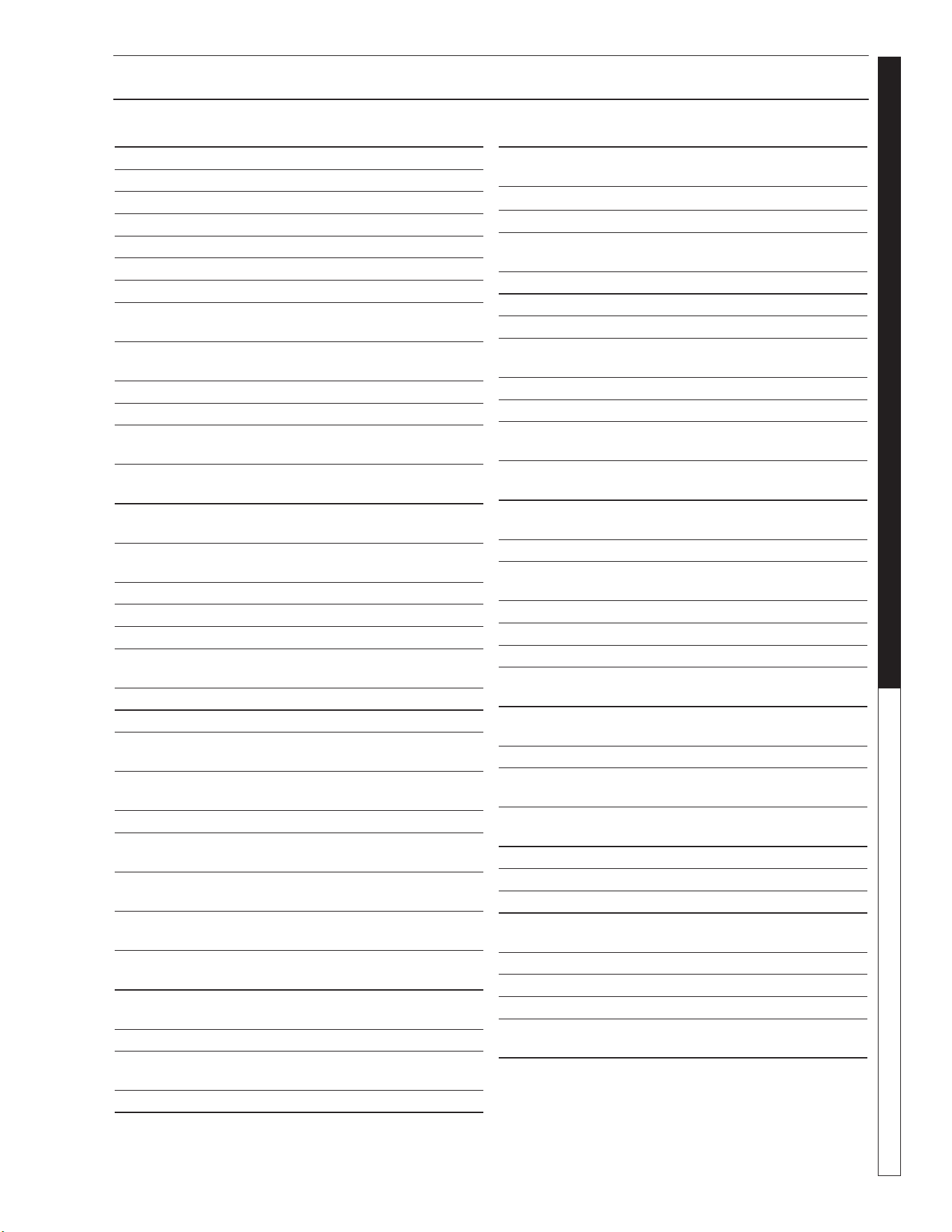
WATERMAZE CL-304 • 8.913-972.0-A
OPERATOR’S MANUAL WATER TREATMENT SYSTEM
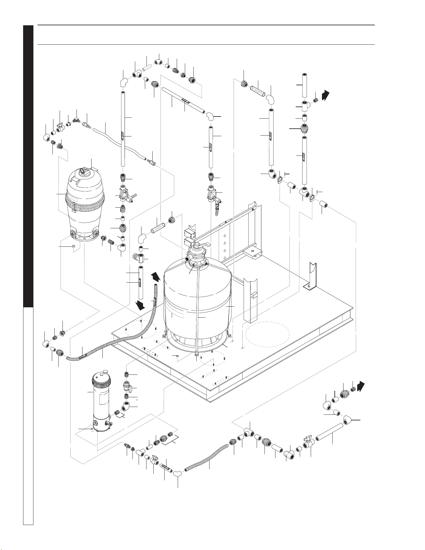
26
89139720-4
12
13
10
WATER PANEL EXPLODED VIEW
Water Panel
(Front View)
4
10
9
12
14
7
8
13
1
7
10
5
17
7
19
2
3
16
15
11
14
6
1
7
Water Panel
(Back View)
5
18

WATERMAZE CL-304 • 8.913-972.0-A
27
WATER TREATMENT SYSTEM
OPERATOR’S MANUAL
WATER PANEL EXPLODED VIEW PARTS LIST
ITEM PART NO. DESCRIPTION QTY
1 8.706-790.0 Nipple, 1/2" Close 3
2 8.706-860.0 Tee, 1/2" Street 1
3 9.802-131.0 Elbow, 1/2" JIC x 1/2", 90° 1
4 9.803-557.0 Elbow, 3/4" SAE x 3/4". 90° 1
5 9.802-132.0 Elbow, 3/4" JIC x 1/2", 90° 2
6 8.706-881.0 Nipple, 3/4" Pipe x 1/2 Pipe 1
7 8.706-928.0 Bushing, 1" x 1/2"
Black Poly Reducer 4
8 8.706-968.0 Fitting, 3/4" Garden Hose x
1/2" Male 3
9 9.802-146.0 Swivel, 1/2" MP x 3/4" GHF
w/Strainer 1
10 9.802-151.0 Swivel, 1/2" JIC Fem,
Push-On 2
11 8.913-103.0 Plate, Water Manifold 1
12 8.707-211.0 Valve, 1/2" 8201 Brass Ball
400 PSI 1
13 8.707-214.0 Valve, 3/4" 8201 Brass Ball 1
14 8.716-697.0 Solenoid, Water Maze, PVC
24V 2
15 9.802-259.0 Hose, 1/2" Push-on 1.25 ft
16 8.707-000.0 Connector, 1/2", Anchor 4
17 9.802-128.0 Nipple, 1/2" x 1/2" JIC 1
18 8.900-520.0 Label, Water Connection
Panel 1
19 9.802-799.0 Screw, #14 x 1" Tek Blk,
Zinc 2
WATERMAZE CL-304 • 8.913-972.0-A
OPERATOR’S MANUAL WATER TREATMENT SYSTEM
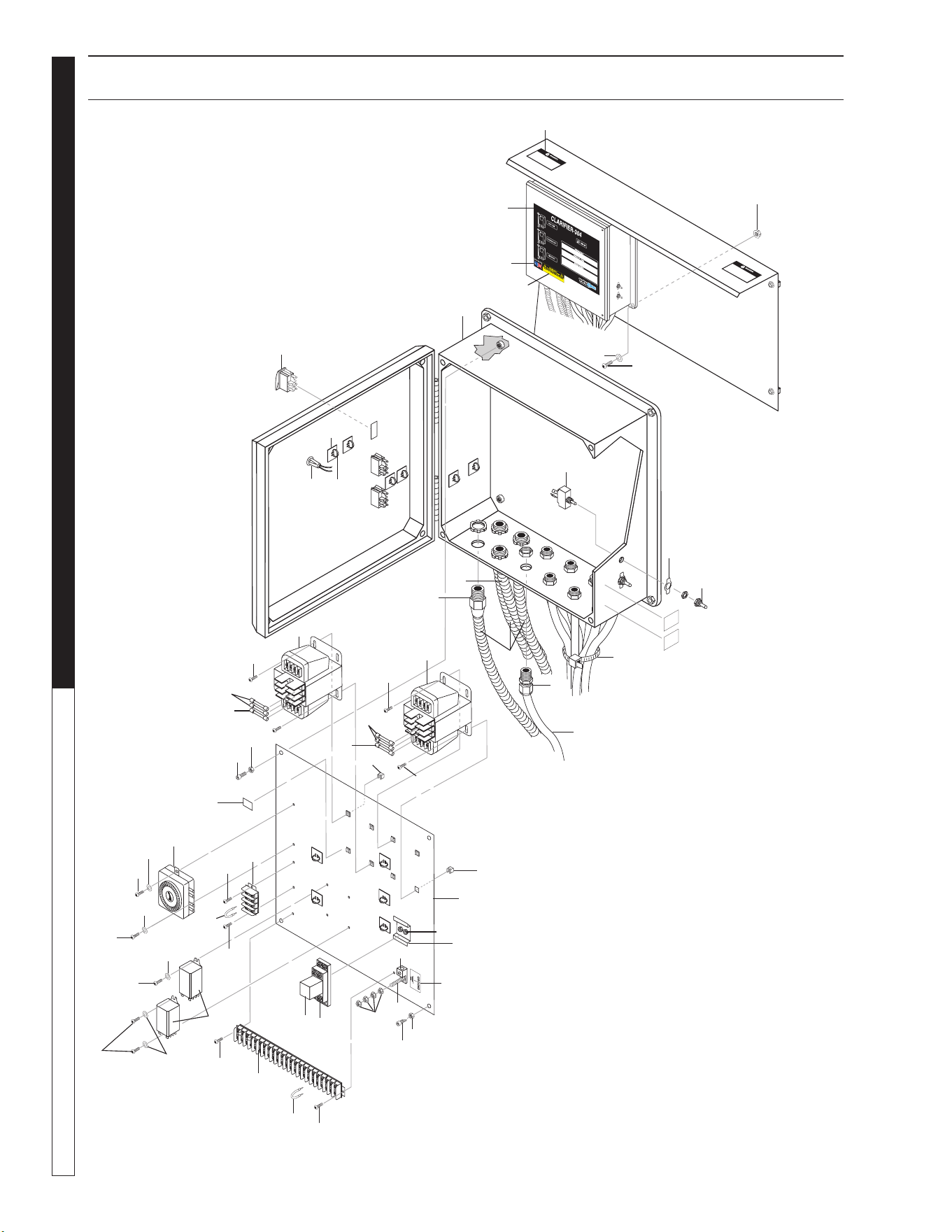
28
89139720-6
240
V
36
6
10
39
12
4
9
27
28
8
13
1
7
44
45
17
21
5
24
19
2
3
23
16
22
11
14
26
29
32
20
25
31
31
30
32
32
35
33
34
33
37
38
40
43
41
42
ELECTRICAL CONTROL PANEL EXPLODED VIEW
15
18
32
5
41
44
41
34
34
34
44
34
30
34
32
33
44

WATERMAZE CL-304 • 8.913-972.0-A
29
WATER TREATMENT SYSTEM
OPERATOR’S MANUAL
ELECTRICAL CONTROL PANEL EXPLODED VIEW PARTS LIST
ITEM PART NO. DESCRIPTION QTY
1 9.802-451.0 Switch, Rocker, Carling
w/Green Lens 875858 3
2 8.716-078.0 Switch, Toggle,1-1/2 HP,
1-Pole 2
3 8.716-081.0 Protector, Toggle Switch,
Wtrprf 2
4 8.716-083.0 Plate, On-Off ,
Toggle Switch 2
5 8.933-007.0 Fuse, KTK-R1 600V
Midget Fuse 4
6 9.803-977.0 Fuse, 2-1/2 Amp, 250V,
FNM2-1/2 1
7 8.716-209.0 Relay, 240V,
RH2B-UL-AC240
1
8 9.802-467.0 Base, Relay, SH2B-05, Idec 1
9 8.716-253.0 Timer,
24 Hour Pin, 120V 20A
1
10 8.716-264.0 Relay, Sky Mfg. 120V
#SKHT-1X 2
11 8.716-281.0 Box, Plastic,14 x 16 x 6.75
w/Hinged Lid 1
12 9.802-491.0 Block, Terminal, 4 Pole 1
13 8.716-414.0 Block, Terminal, 23 Pole 1
14 9.802-514.0 Strain Relief, LT, STR,
1/2 NPT, .23-.45D 10
15 9.802-551.0 Transfrmer,240/480V-120V,
50/60Hz, .050KVA 1
16 8.716-883.0 Transformer, 208/230/460V-
24/115V, .050KVA 1
17 8.913-206.0 Standoff, Elec Box 1
18 9.802-448.0 Conduit, Wtr. Tight,
Flex,1/2" 10 Ft
19 9.803-652.0 Light, Indicator, Green-
28 Volt 1
20 9.802-463.0 Fuse, Paper, Buss Fnm-1/2,
250V Midget Td 1
21 9.800-040.0 Label, Ground Symbol 1
22 8.900-313.0 Label Assembled In USA 1
23 8.718-887.0 Nut, 5/16" Whiz Loc Flange,
SS 4
24 9.802-448.0 Conduit,Wtr. Tight,
Flex,1/2" 7.5 Ft
25 9.802-805.0 Washer, 5/16", Flat, SAE, SS 1
26 8.718-621.0 Bolt, 5/16" x 1", HH, NC, S/S 4
27 8.900-522.0 Label, CLP Warning, Do Not
Stand or Step 2
28 9.802-422.0 Cord, Service, SEO, 16/2 /Ft
Coleman 59.5 Ft
ITEM PART NO. DESCRIPTION QTY
29 9.802-511.0 Cable Tie, Black, 11" 3
30 9.802-494.0 Bar Jumper 4
31 9.802-791.0 Nut, Cage, 10/32" x 16 Ga 8
32 9.802-759.0 Screw, 10/32" x 1/2"
BHSOC Blk 12
33 8.718-936.0 Screw, 8 x 1/2", Phillips,
Zinc Plate Tek 6
34 8.718-937.0 Screw, #8 x 3/4", Phillips, Zinc
Pltd, Hex,T 6
35 8.724-560.0 Label, Clarifier CL-304 1
36 8.716-547.0 Connector, 1/2" L/T, Straight,
Black 4
37 9.800-016.0 Label, Disconnect Power
Supply 1
38 8.716-533.0 Clamp, Tie Wrap, Adhesive 13
39 9.802-510.0 Cable, Tie, 4" Black 13
40 8.716-460.0 Terminal, Grounding Lug 1
41 9.802-695.0 Nut, 10/32", Keps 8
42 9.802-762.0 Screw, 10/32" x 1-1/4"
RH, SL, Blk 1
43 9.802-457.0 Din Rail, 35mm 1"
44 9.803-675.0 Washer, SS # 8 Flat 6
45 8.900-511.0 Label, 220 Volts 1
WATERMAZE CL-304 • 8.913-972.0-A
OPERATOR’S MANUAL WATER TREATMENT SYSTEM
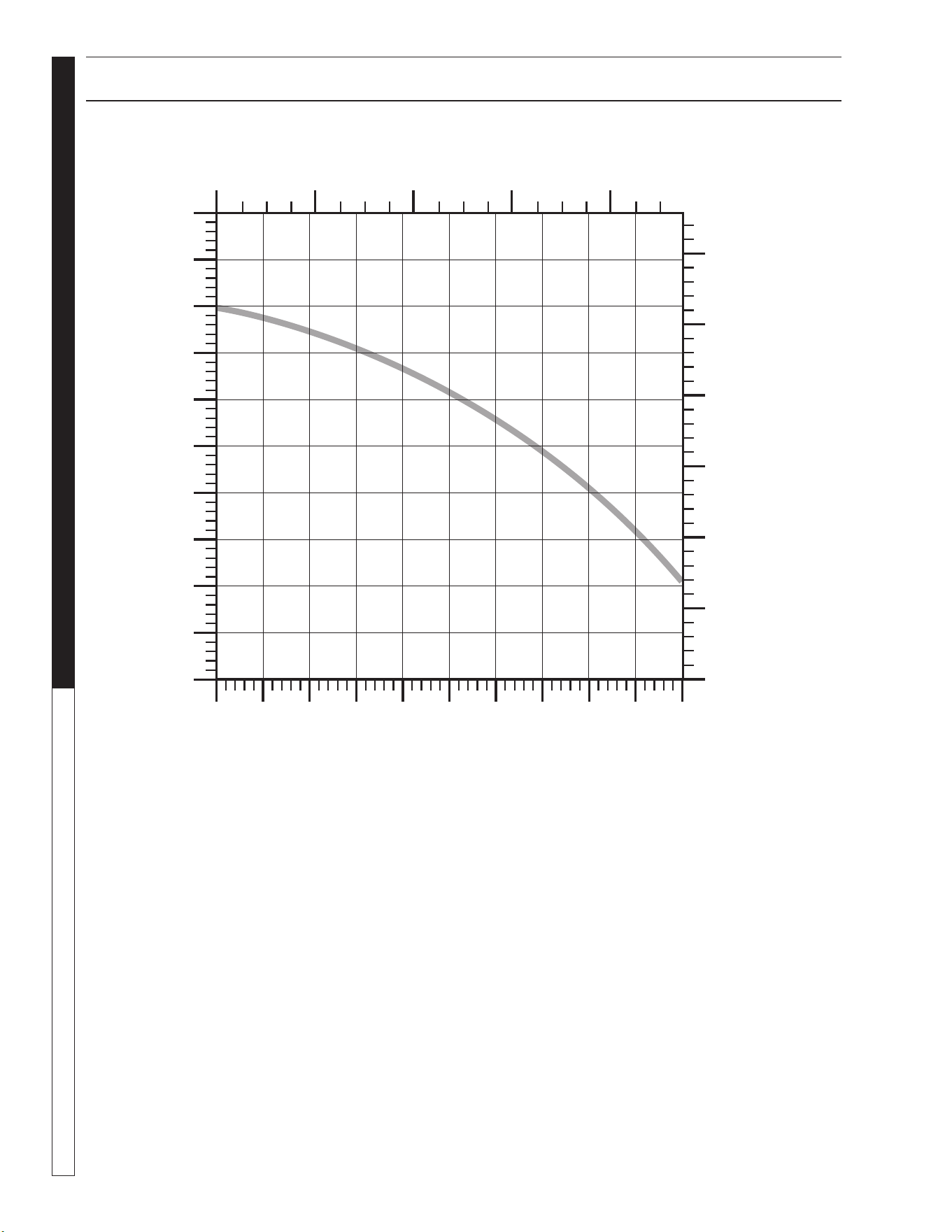
30
SUBMERSIBLE SUMP PUMP SPECIFICATION
Flow - (Liters/Minute)
04080 120 160
Head - (Feet)
Flow - (Gallons/Minute)
0
0
5
10
15
20
25
10 20 30 40 50
Head - (Meters)
0
1.25
2.50
3.75
5.00
6.25
7.50
WATERMAZE CL-304 • 8.913-972.0-A
31
WATER TREATMENT SYSTEM
OPERATOR’S MANUAL
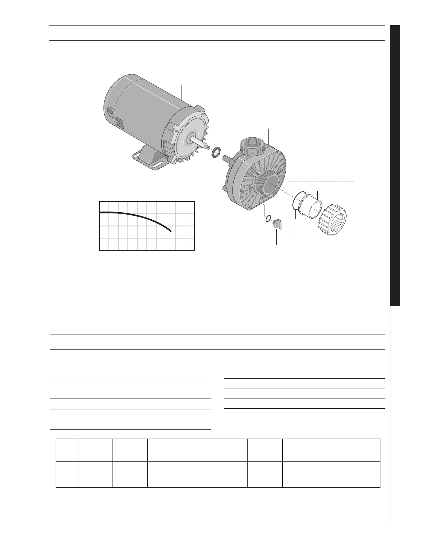
OZONE PUMP EXPLODED VIEW
ITEM PART NO. DESCRIPTION
QTY
1 8.726-026.0 Motor, 3/4 HP, 230V 1
2 NA Slinger 1
3 8.726-024.0 Pump, 3/4 HP, Wet End 1
4 NA Drain Plug 1
5 NA O-Ring, Drain Plug 1
HP Volts Phase
Size
Inlet Outlet
Running
Amps
Max.
Pressure
Max.
Water Temp.
3/4 230V 1 1-1/2" FPT/ 1-1/2"FPT/
1-1/2" MBT 1-1/2" MBT
5.7 40 PSI 104°F/40°
ITEM PART NO. DESCRIPTION
QTY
6 NA O-Ring 1
7 NA Adapter, Union 1-1/2” Slip 1
8 NA Collar, Union 1
Kit:
6-8 8.750-270.0 Fitting, Compression, 1-1/2" Slip
Part # 8.917-760.0
OZONE PUMP EXPLODED VIEW PARTS LIST
40
20
0
20 40 60 80
U.S. GALLONS PER MINUTE
TOTAL HEAD IN FEET
1
2
3
4
5
6
7
8
Not Included
With Pump
WATERMAZE CL-304 • 8.913-972.0-A
OPERATOR’S MANUAL WATER TREATMENT SYSTEM
32
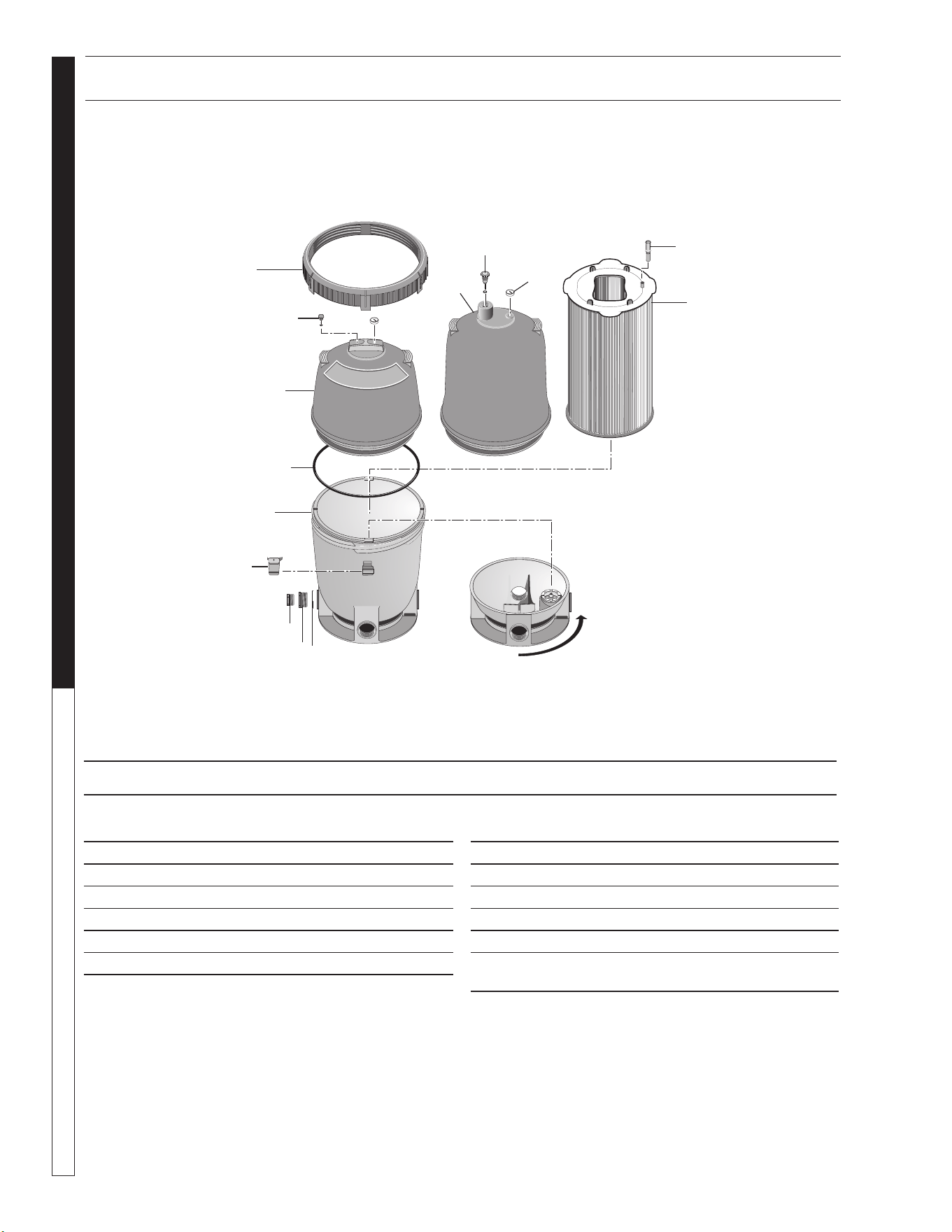
CARTRIDGE FILTER ASSEMBLY
PART #8.723-204.0
ITEM PART NO. DESCRIPTION QTY
1 8.750-004.0 Posi-Lok Ring 1
2 8.750-005.0 Air Release Valve Assembly 1
3 NA Tank Shell Upper Half 1
4 8.750-006.0 Tank O-Ring 1
5 NA Tank Shell Lower Half 1
6 NA Safety Latch for Ring 1
ITEM PART NO. DESCRIPTION QTY
7 NA 1-1/2" NPT Plug 1
8 NA O-Ring 1
9 NA Adapter Fitting 1
10 8.750-007.0 Pressure Gauge 1
11 NA Air Bleed Assembly 1
12 8.723-215.0 Filter Element 125 sq. ft.,
10 Micron 1
OUTLET
OUTLET
RELEASE
RELEASE
Base rotated 90 ° to show
check valve installed.
1
2
3
4
6
7
9
8
3
2
10
11
12
5
EXPLODED VIEW PARTS LIST
WATERMAZE CL-304 • 8.913-972.0-A
33
WATER TREATMENT SYSTEM
OPERATOR’S MANUAL
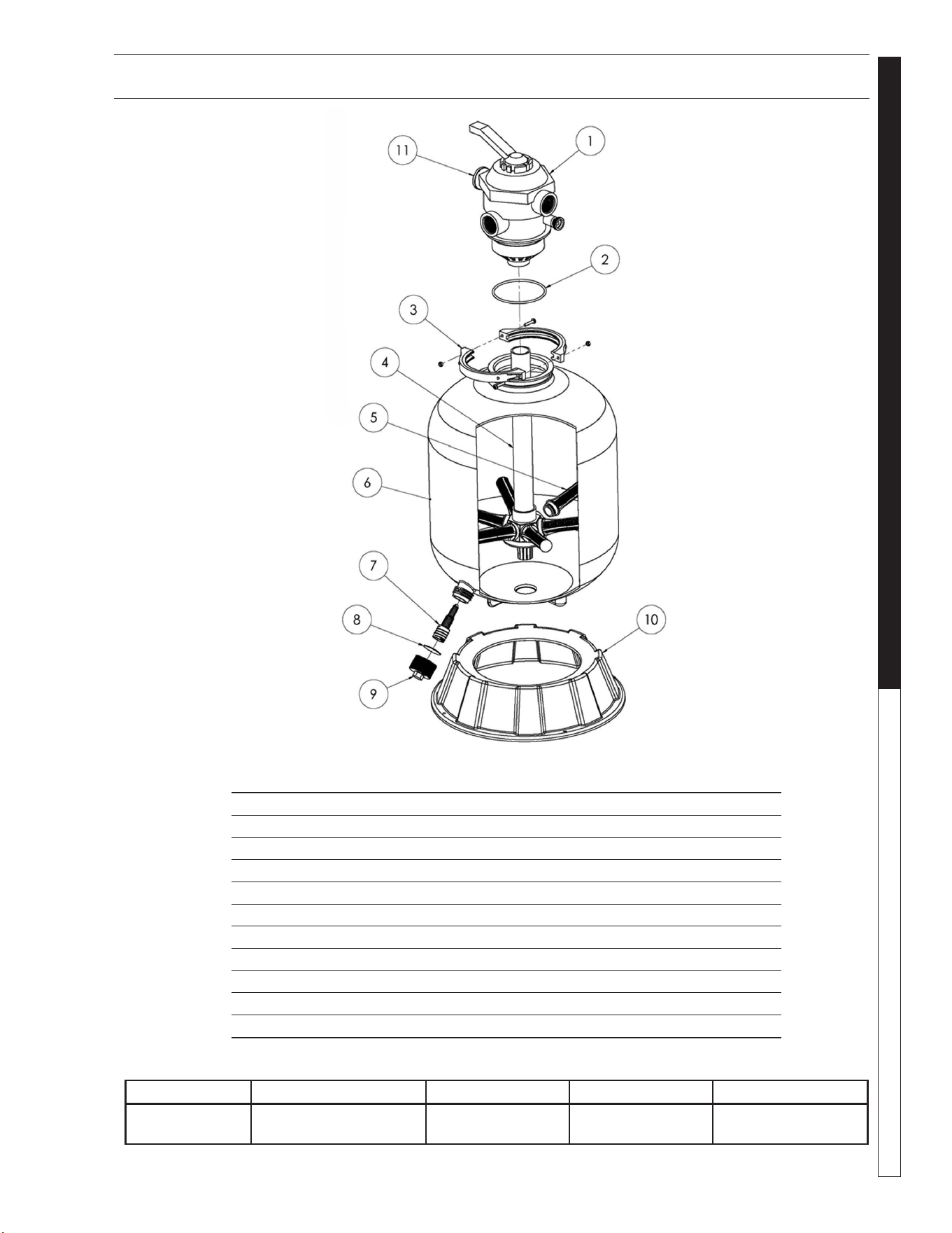
MULTI-MEDIA FILTER ASSEMBLY
# 8.726-028.0
ITEM PART NO. DESCRIPTION QTY
1 8.726-030.0 Multiport Valve, Top Mount 1
2 NA O-Ring, Valve Body 1
3 NA Clamp Assembly 1
4 NA Piping Assembly 1
5 NA Lateral 8
6 NA Filter Tank w/Drain 1
7 NA Drain Lateral 1
8 NA Gasket, Drain Cap 1
9 NA Drain Cap 1
10 NA Pedestal 1
11 NA Pressure Gauge 1
Tank Diameter Max. Working Pressure Vert. Clearance Max. Water Temp Valve
24" 40 PSI 58" 95°F 6 Position
1-1/2" FPT/MBT
WATERMAZE CL-304 • 8.913-972.0-A
OPERATOR’S MANUAL WATER TREATMENT SYSTEM
34
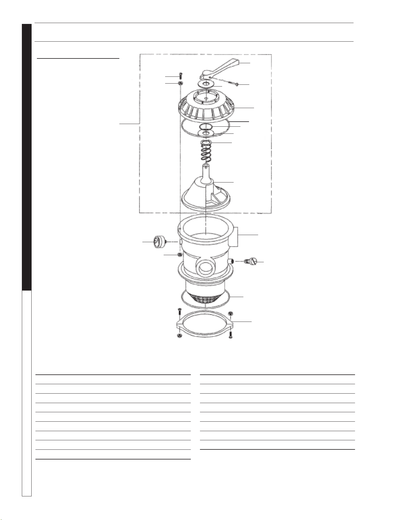
6 POSITION VALVE ASSEMBLY
6 POSITION VALVE
1-1/2" PORTS
8.726-030.0
ITEM PART NO. DESCRIPTION QTY
1 NA Handle 1
2 NA Washer, Plastic 2
3 NA Screw, Handle 1
4 NA Valve Top, Black 1
5 NA O-Ring Diverter Shaft 1
6 NA O-Ring 1
7 NA Spring 1
8 NA Diverter w/Gasket 1
9 NA Screw, #10-24 1
ITEM PART NO. DESCRIPTION QTY
10 NA Washer 6
11 NA Nut, #10-24 6
12 NA Valve Body w/Diff - Clamp Style 1
13 NA Air Bleeder w/ O-Ring 1
14 NA O-Ring 1
15 NA Clamp Assembly (See note) 1
16 NA Pressure Gauge 1
17 NA Valve Top Assy (items 1-8) 1
Note: Clamp halves, nuts and bolts sold only in Assembly
2
5
8
11
14
3
6
9
12
15
1
4
7
10
13
16
17
2
WATERMAZE CL-304 • 8.913-972.0-A
35
WATER TREATMENT SYSTEM
OPERATOR’S MANUAL
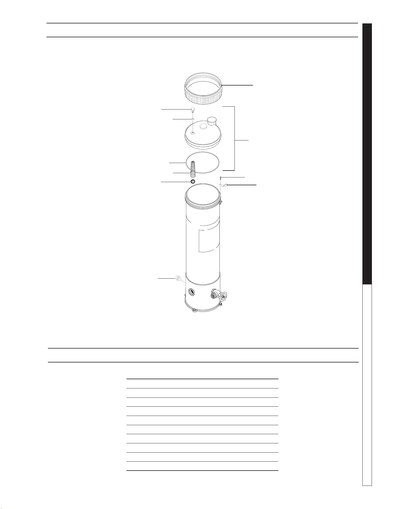
ITEM PART NO. DESCRIPTION QTY
1 NA Lock Ring 1
2 NA Lid Assembly 1
3 8.750-043.0 Vent Valve 1
4 8.750-044.0 O-Ring vent Valve 1
5 8.750-045.0 O-Ring, Lid, Housing 1
6 NA Lock Screw 7
7 NA Lock Spring 1
8 NA Screen 1
9 NA Check Ball 2
10 NA Plug, 1/2" Threaded 1
SANITIZER ASSEMBLY
PART #8.723-207.0
1
3
4
2
5
8
9
6
7
10
EXPLODED VIEW PARTS LIST
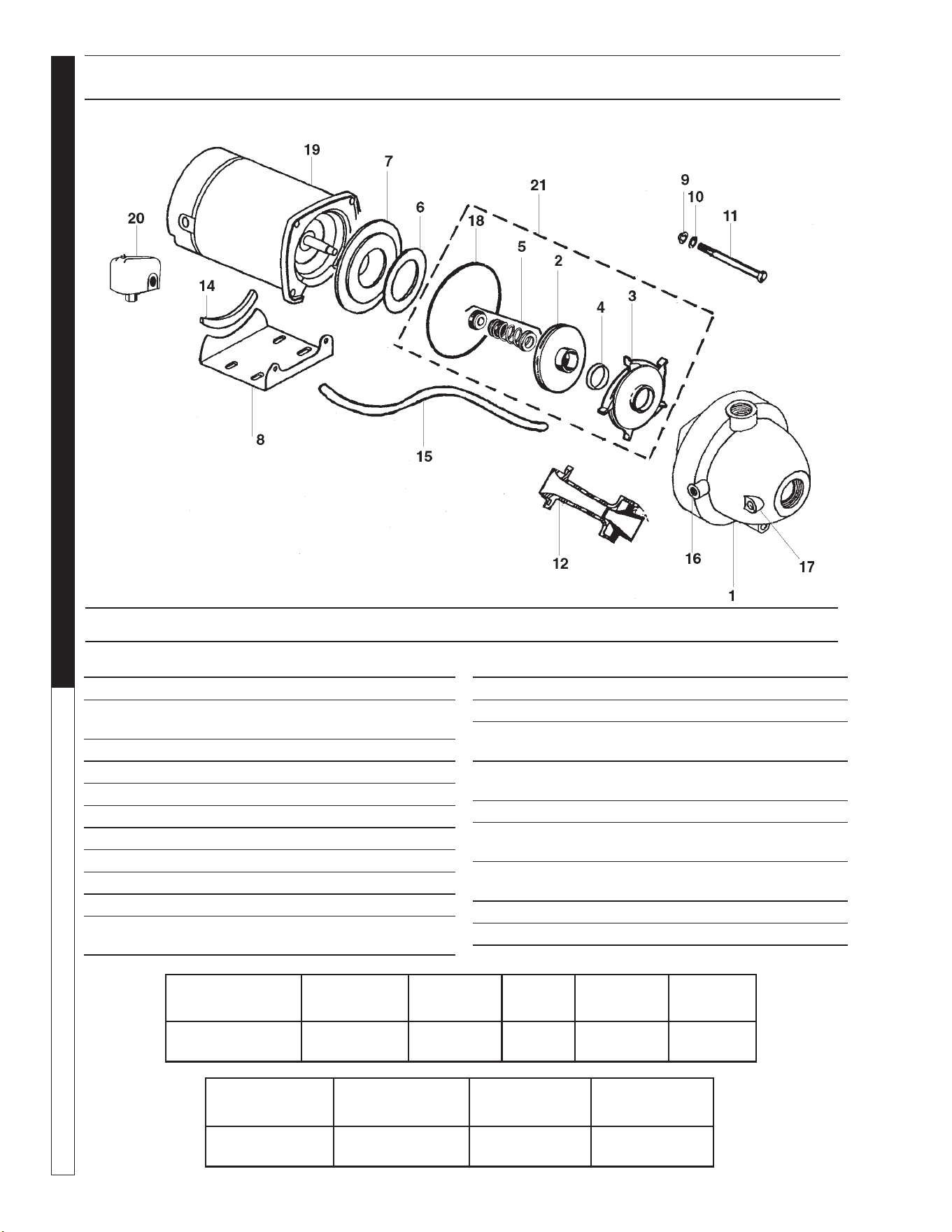
WATERMAZE CL-304 • 8.913-972.0-A
WATER TREATMENT SYSTEM
Troubleshooting Guide
36
TRANSFER PUMP ASSEMBLY
PART #8.715-383.0
ITEM PART NO. DESCRIPTION QTY
12 NA Noz./Venturi f/5CY 1
14 NA Base Protector 1
15 NA Tube 1/4" x 14-1/2"
Poly-Black 1
16 NA Barb Fitting 90 Degree
Elbow 1
17 NA Plug 1/4" Galv. 1
18 NA O-Ring 6" x 3/8" x 3/16",
In Kit 1
19 NA Motor 1/2 HP 3450 RPM
56Z Frame 1
20 8.716-154.0 Pressure Switch Set 20/40 1
21 8.716-795.0 5 Cy. Impeller Repair Kit 1
Brand Model No. Listing Hp Volts Phase
Cyclone 5CY CSA 1/2 115/230 1
ITEM PART NO. DESCRIPTION QTY
1 NA Case Assembly 1
2 NA Impeller 1/2 HP
#2794 4-60D, In Kit 1
3 NA Diffuser, In Kit 1
4 NA Wear Ring, In Kit 1
5 NA Mechanical Seal, In Kit 1
6 NA Disk 1
7 NA Seal Plate 6-1/2" D 1
8 NA Base w/ #14 Rbr. Protector 1
9 NA Hex Nut 3/8" - 16 PL. 4
10 NA Lock Washer 3/8" Reg. 4
11 NA Hex Capscrew
3/8"-16 x 2-3/4" PL. 4
Size
Inlet Outlet
Running
Amps
Max.
Pressure
Max.
Water Temp.
1-1/4" 1" 12/6 62 psi 120°F/50°C
EXPLODED VIEW PARTS LIST
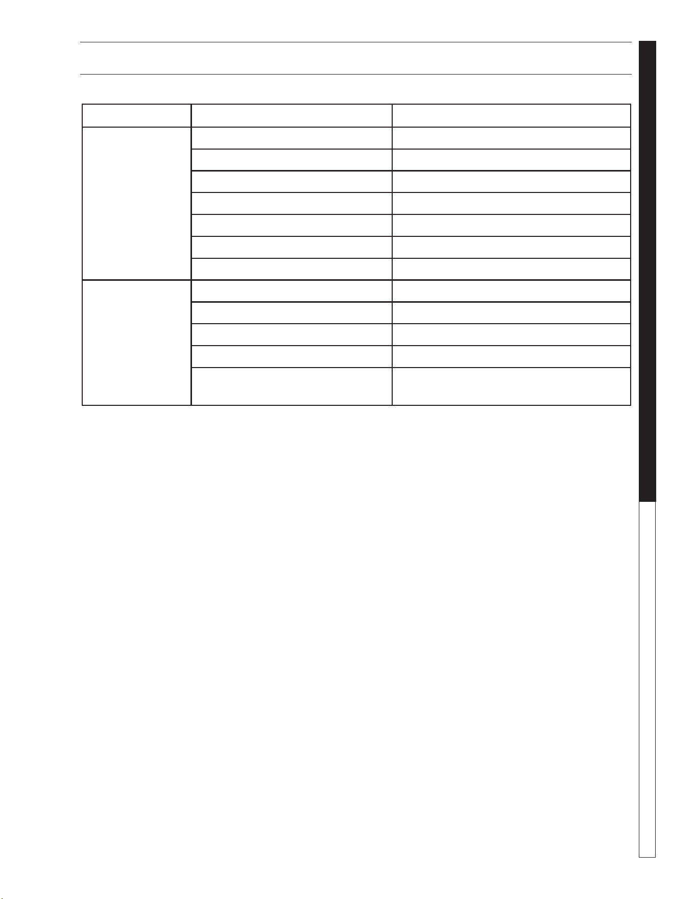
WATERMAZE CL-304 • 8.913-972.0-A
37
WATER TREATMENT SYSTEM
Troubleshooting Guide
TROUBLESHOOTING - CL
PROBLEM POSSIBLE CAUSE SOLUTION
NO FLOW OF
WATER INTO
THE CL-304
Control switch not in "ON" position Turn switch to "ON" position.
Power not turned "ON" at breaker box Turn "ON" power at breaker box.
Float in sump in down position Add water to sump.
Debris in sump impeller Unplug pump and remove from container.
Flow valve closed Open valve.
Dirt lodged in control valve Clean as needed.
Frozen water in lines or valves Thaw out with warm water.
WATER FLOWING
OVER CL-304
TANK
Tank not level Level tank.
Water coming in faster than 5 gpm Adjust flow control valve.
Discharge line plugged Remove obstruction.
Filter pump "Off" Turn pump switch "On."
Top float in cone tank stuck or short-
ed out
Clean and move so it can float freely/replace.
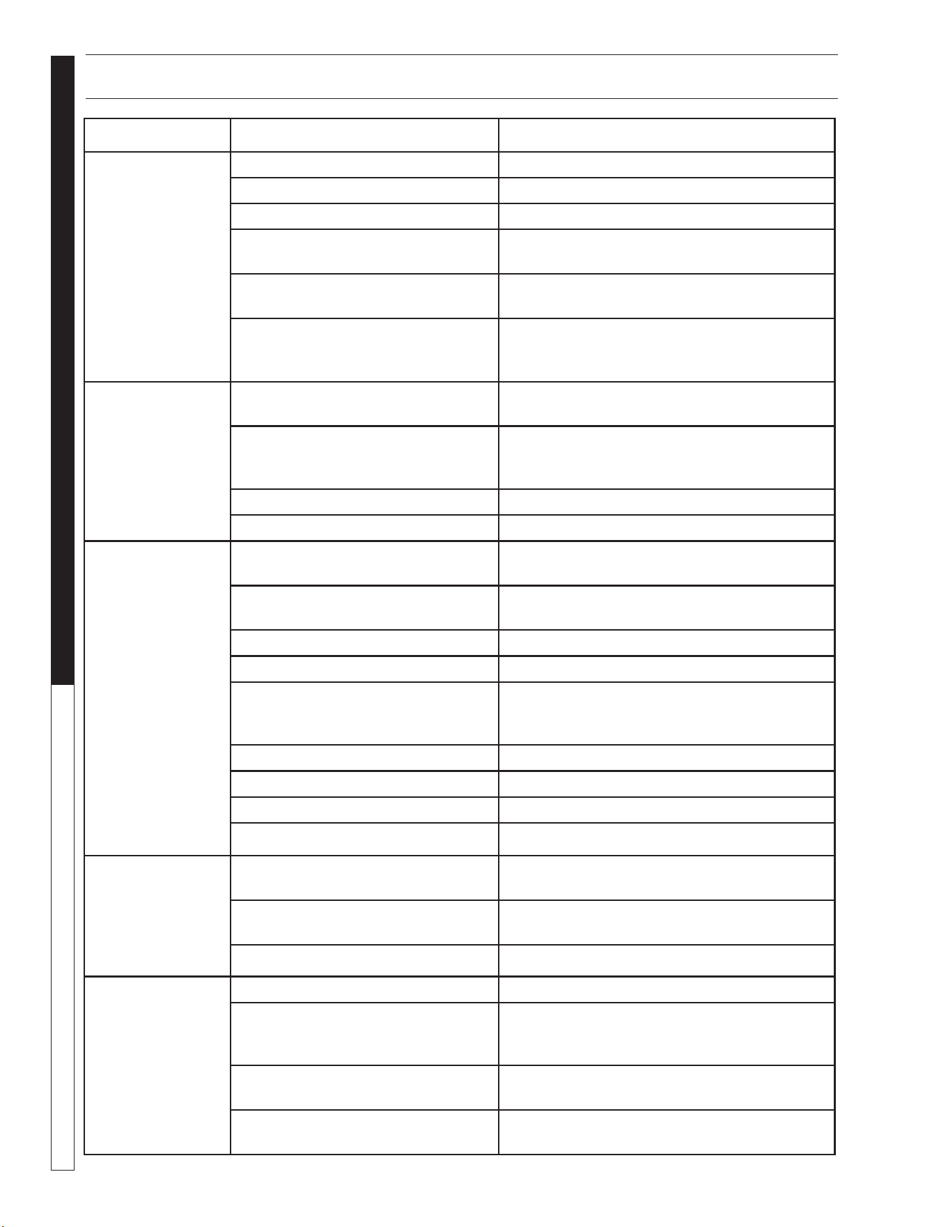
WATERMAZE CL-304 • 8.913-972.0-A
WATER TREATMENT SYSTEM
Troubleshooting Guide
38
TROUBLESHOOTING - PUMP
PROBLEM POSSIBLE CAUSE SOLUTION
PUMP DOES
NOT TURN ON
Circuit breaker shut "OFF" Turn "ON" circuit breaker.
Accumulation of trash on float Clean float.
Float obstruction Check float path and provide clearance.
Defective switch Have pump serviced by authorized service
center.
Defective motor Have pump serviced by authorized service
center.
Low line voltage If voltage under recommended minimum,
check size of wiring from main switch on
property. If OK, contact power company.
PUMP WILL NOT
SHUT OFF
Float obstruction Check float and float path and
provide clearance.
Pump is air locked (Transfer Pump) Shut power off for approximately 1 minute,
then restart. Repeat several times to clear air
from pump.
Liquid inflow matches pump capacity Larger pump required.
Defective float switch Disconnect switch, check with ohmmeter.
PUMP RUNS
BUT DOES NOT
DISCHARGE
LIQUID
Check valve installed backwards
(Transfer Pump)
Check flow indicating arrow on check valve
body to insure it is installed properly.
Check valve stuck or plugged (Trans-
fer Pump)
Remove check valve and inspect for proper
operation.
Lift too high for pump Check rating table.
Inlet to impeller plugged Pull pump and clean.
Low line voltage If voltage under recommended minimum,
check size of wiring from main switch
on property. If OK, contact power company.
Clogged impeller Remove housing, unclog.
Faulty motor protector Replace pump.
Very low head or lift Increase head or lift.
Sump pit too small Increase size of pit.
PUMP DOES NOT
DELIVER RATED
CAPACTIY
Low voltage, speed too slow Check for proper supply voltage to make
certain it corresponds to nameplate voltage.
Impeller or discharge pipe is clogged Pull pump and clean. Check pipe for scale or
corrosion.
Impeller wear due to abrasives Replace worn impeller.
PUMP CYCLES
CONTINUALLY
Check valve leaking (Transfer Pump) Inspect check valve for correct operation.
Low line voltage If voltage under recommended minimum, check
size of wiring from main switch on property. If
OK, contract power company.
Worn or defective pump parts or
plugged impeller
Replace worn parts or entire pump. Clean parts
if required.
Pump air locked Turn pump "ON" and "OFF" several times. Fill
hose manually with water.
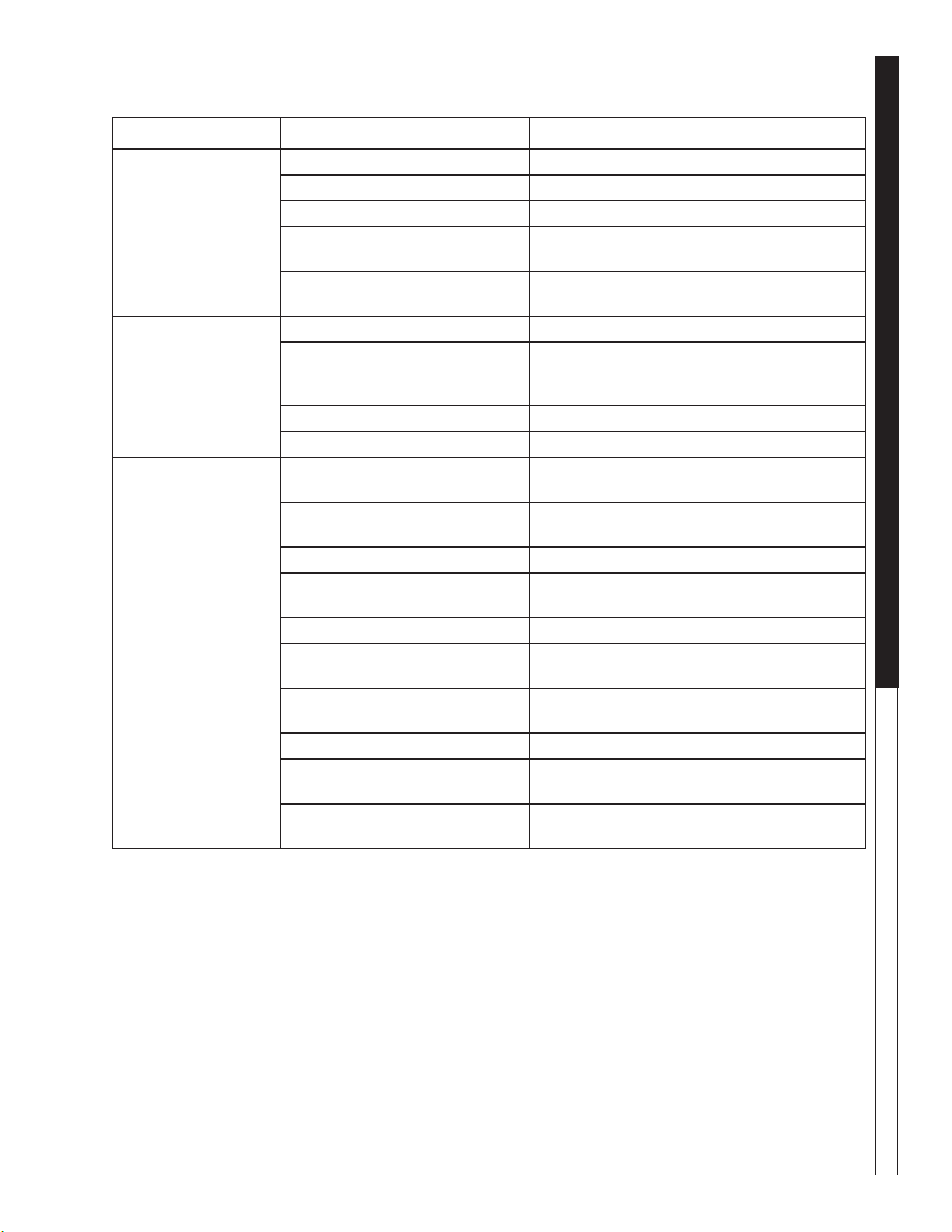
WATERMAZE CL-304 • 8.913-972.0-A
39
WATER TREATMENT SYSTEM
Troubleshooting Guide
TROUBLESHOOTING - PUMP MOTOR
PROBLEM POSSIBLE CAUSE SOLUTION
MOTOR WILL
NOT RUN
Disconnect switch is "OFF" Be sure switch is "ON."
Breaker is tripped Reset breaker.
Starting switch is defective Replace starting switch.
Wires at motor are loose, discon-
nected or wired incorrectly
Refer to instructions on wiring. Check and
tighten all wiring.
Pressure switch contacts are dirty
(Transfer Pump)
Clean by sliding piece of plain paper
(or crocus cloth) between contacts.
MOTOR RUNS HOT
AND OVERLOAD
KICKS OFF
Motor is wired incorrectly Refer to instructions on wiring.
Voltage is too low Check with power company. Install heavier
wiring if wire size is too small. See wiring
instructions.
Pump cycles too frequently See section on pump cycles continually.
Defective float switch Disconnect switch, check with ohmmeter.
MOTOR RUNS
BUT NO WATER IS
DELIVERED
Pump in a new installation did not
pick up prime because of:
a. Improper priming a. Re-prime ( 3 or 4 times may be needed) by
stopping and starting motor several times.
b. Air leaks b. Check all connections on suction line.
c. Leaking check valve
(Transfer Pump)
c. Clean and or replace check valve.
Pump has lost its prime through:
a. Air leaks a. Check all connections on suction line, jet
and shaft seal.
b. Water level below suction of
pump
b. Lower suction line into water and re-prime.
Jet or impeller is plugged Clean jet or impeller. See Maintenance.
Check valve is stuck in closed
position
Replace check valve.
Pipes are frozen Thaw pipes. Bury pipes below frost line. Heat
pipes below frost line. Heat pit or pump house.
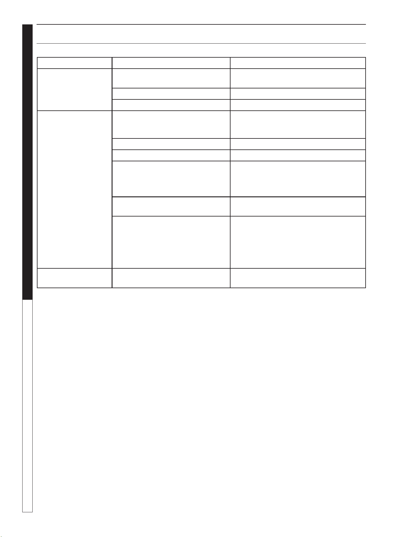
WATERMAZE CL-304 • 8.913-972.0-A
WATER TREATMENT SYSTEM
Troubleshooting Guide
40
PROBLEM POSSIBLE CAUSE SOLUTION
RUNNING AT HIGH
PRESSURES
Multi-Media or carbon filter coated
with normal accumulation of dirt, etc
Backwash is needed.
Cartridge filter plugged Cleaning is needed.
Obstruction in line Remove obstruction.
DROP OFF
OF DISCHARGE
FLOW
Multi-Media or carb absorb filter
coated with normal accumulation of
dirt, etc
Backwash is needed.
Valve #1 closed Open valve.
Cartridge filter clogged Clean.
Pump impeller vanes clogged Cleaning with a stiff wire through the pump
inlet opening will usually work. Alternate
method would be to disassemble and
clean.
Air leak on suction side of pump Check cover gasket, hose, clamps, etc.
Replace or tighten as necessary.
Electric motor running less than
rated RPM (underspeed)
Consult pump and motor troubleshooting
guide.
NOTE: Most motor problems are due to:
1. Undersized or improper wiring.
2. Power cutbacks or a combination of
both.
SHORT CYCLES
Multi-Media or carbasorb filter loaded
to capacity with dirt, etc
Backwash.
TROUBLESHOOTING - FILTER
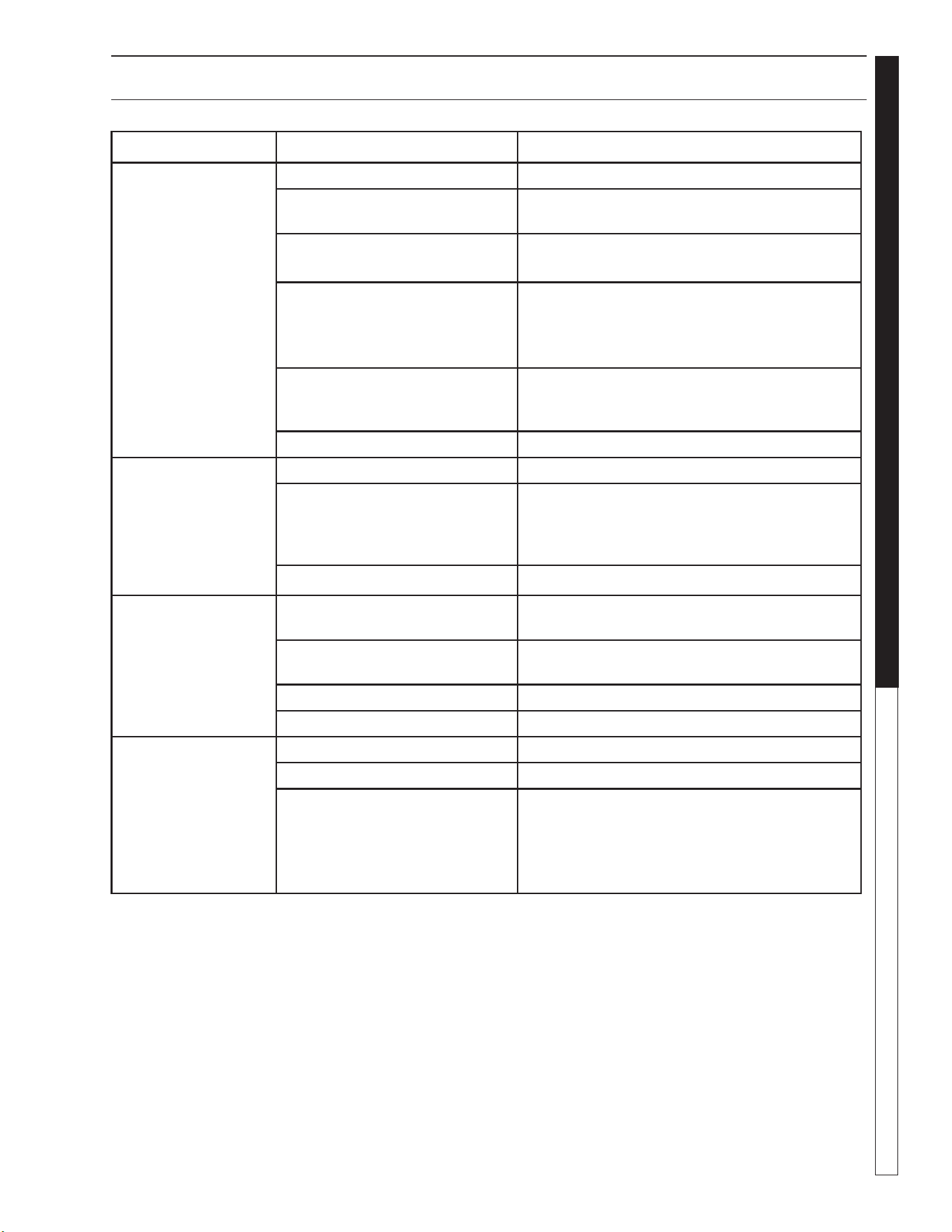
WATERMAZE CL-304 • 8.913-972.0-A
41
WATER TREATMENT SYSTEM
Troubleshooting Guide
TROUBLESHOOTING - WATER SOLENOID
PROBLEM POSSIBLE CAUSE SOLUTION
VALVE LEAKS
WHEN "OFF"
Dirt or debris on diaphragm seat Clean diaphragm seat.
Solenoid not fully closed after
manual operation
Turn solenoid clockwise to fully seated
position.
Solenoid O-ring damaged or
twisted
Turn off water, inspect O-ring and reseat if
twisted, replace if damaged.
Diaphragm damaged Turn off water, remove bonnet screws and
inspect diaphragm for nicks or damage.
NOTE: Diaphragm has one bleed hole molded
into it. Replace, if necessary, with diaphragm kit.
Dirt interfering with solenoid
operation
Turn off water, remove solenoid and flush seat-
ing surface in bonnet and at bottom of solenoid
with water.
Solenoid damaged Turn off water supply and replace solenoid.
WATER WON'T
SHUT OFF
Valve in manual "ON" position Turn solenoid clockwise to "OFF" position.
Diaphragm bleed hole blocked Use Manual Flush Mode. Turn water supply
"OFF" and immediately back "ON" to clear
blockage. If still blocked, turn off water and
inspect diaphragm looking for blockage.
Damaged solenoid Turn off water supply and replace solenoid.
LOW OR
INADEQUATE
FLOW
CONDITION
Water running elsewhere using
up pressure
Turn off water that is running elsewhere.
Too many solenoids running at
once
Adjust so water is running to only one
solenoid.
Gate valve not fully open Open gate valve fully.
Pipeline blockage Clear pipeline.
VALVE WON'T
TURN ON
ELECTRICALLY
No power to solenoid Make sure solenoid has power.
Low voltage Make sure there is 24 volts.
No water pressure Make sure water pressure is available to valve.
Turn off water, without cutting wires, unscrew
and swap solenoids between valves. Turn on
water and test again. If problem stems from the
solenoid, replace solenoid.
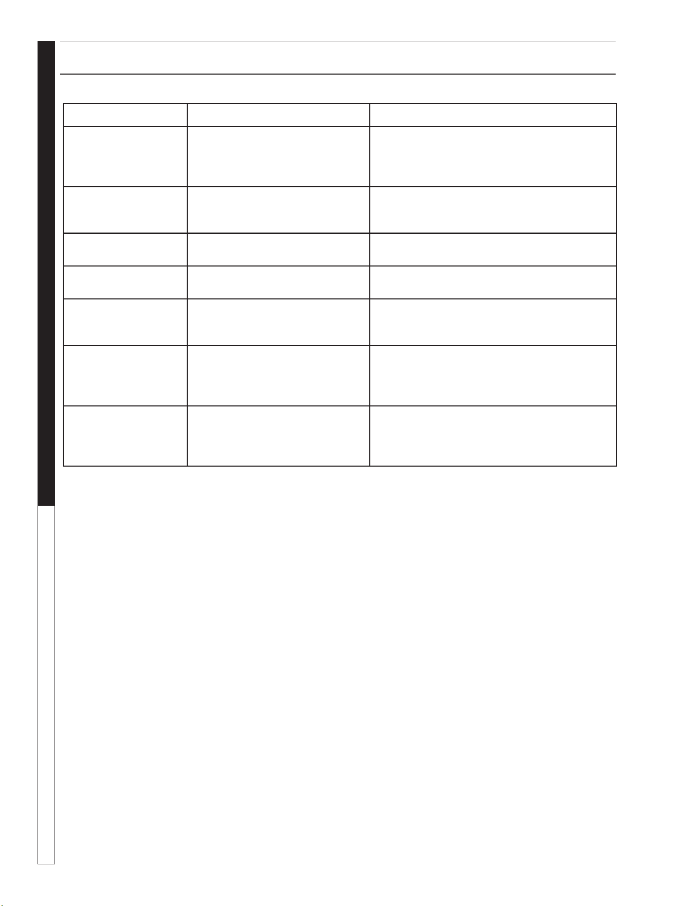
WATERMAZE CL-304 • 8.913-972.0-A
WATER TREATMENT SYSTEM
Troubleshooting Guide
42
TROUBLESHOOTING SEALS
PROBLEM POSSIBLE CAUSE SOLUTION
CRACKED OR
BROKEN
STATIONARY SEAT
(CERAMIC)
Seal ran dry and heated up.
When liquid reached seal faces
it was cooler, causing thermal
cracks
Check to insure seal chamber is full of liquid
before starting pump. On high temperature ap-
plication insure proper flushing at seal faces.
CARBON WASHER
SCORED AND
GROOVED
Dirty system Have system cleaned and flushed. Consider
use of Tungsten Carbide or Silicon Carbide
Rings.
CARBON WASHER
WORN UNEVENLY
Seal improperly installed Check installation instructions for
proper assembly.
FLEXIBLE DIA-
PHRAGM BROKEN
Coupling misalignment Realign pump and motor.
SHORT SEAL
LIFE IN TREATED
SYSTEMS
Treatment level and temperature
higher than anticipated
Use Viton Elastomers, High Temperature
Carbon, Ni Resist Tungsten Carbide or Silicon
Carbide Seat.
BUNA DIAPHRAGM
HARD & BRITTLE.
RAPID CARBON
WEAR.
Air leak on suction side of pump Check cover gasket, hose, clamps, etc.
Replace or tighten as necessary.
DIAPHRAGM SOFT
AND STICKY;
APPEARS TO BE
DISSOLVING.
Bellows not compatible with mate-
rial being pumped
Consult factory for recommendation advising
of pumpage and temperature.
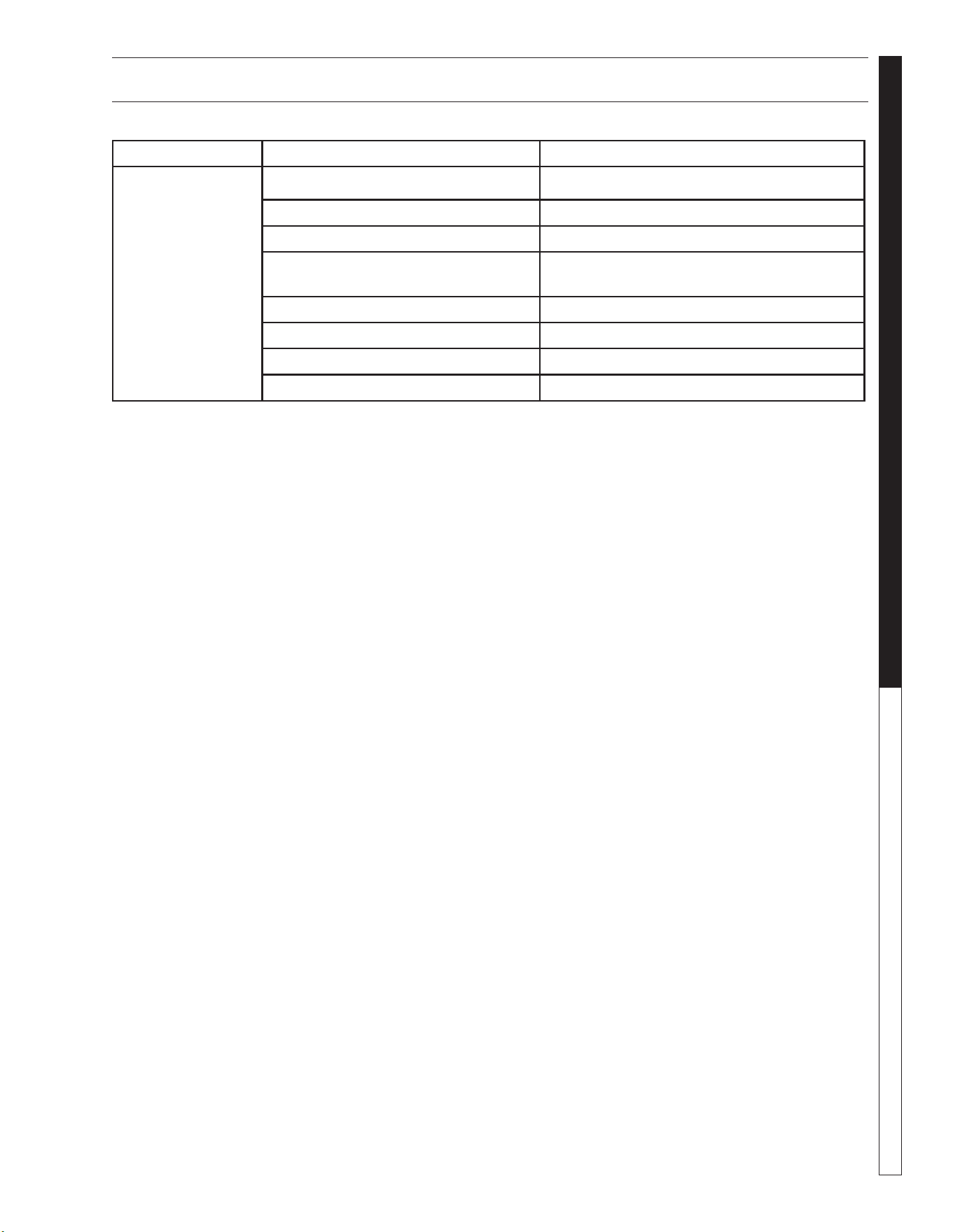
WATERMAZE CL-304 • 8.913-972.0-A
43
WATER TREATMENT SYSTEM
Specifications
TROUBLESHOOTING - OUTLET TO PRESSURE WASHER
PROBLEM POSSIBLE CAUSE SOLUTION
NO FLOW OF
WATER TO THE
PRESSURE
WASHER
Control switch is not in "ON" position Turn switch to the "ON" position.
Breaker is not turned "ON" Turn "ON" the breaker.
Low level float switch is down Check float position.
Debris is in pump impeller Unplug pump and remove from container.
Check impeller. Clean or repair as necessary.
Flow control valve is in "OFF" position Open valve.
No water in 40 gal. tank Check filters. Refill 40 gal. tank.
Dirt is lodged in control valve Clean as necessary.
Frozen water is in lines or valves Thaw out with warm water.
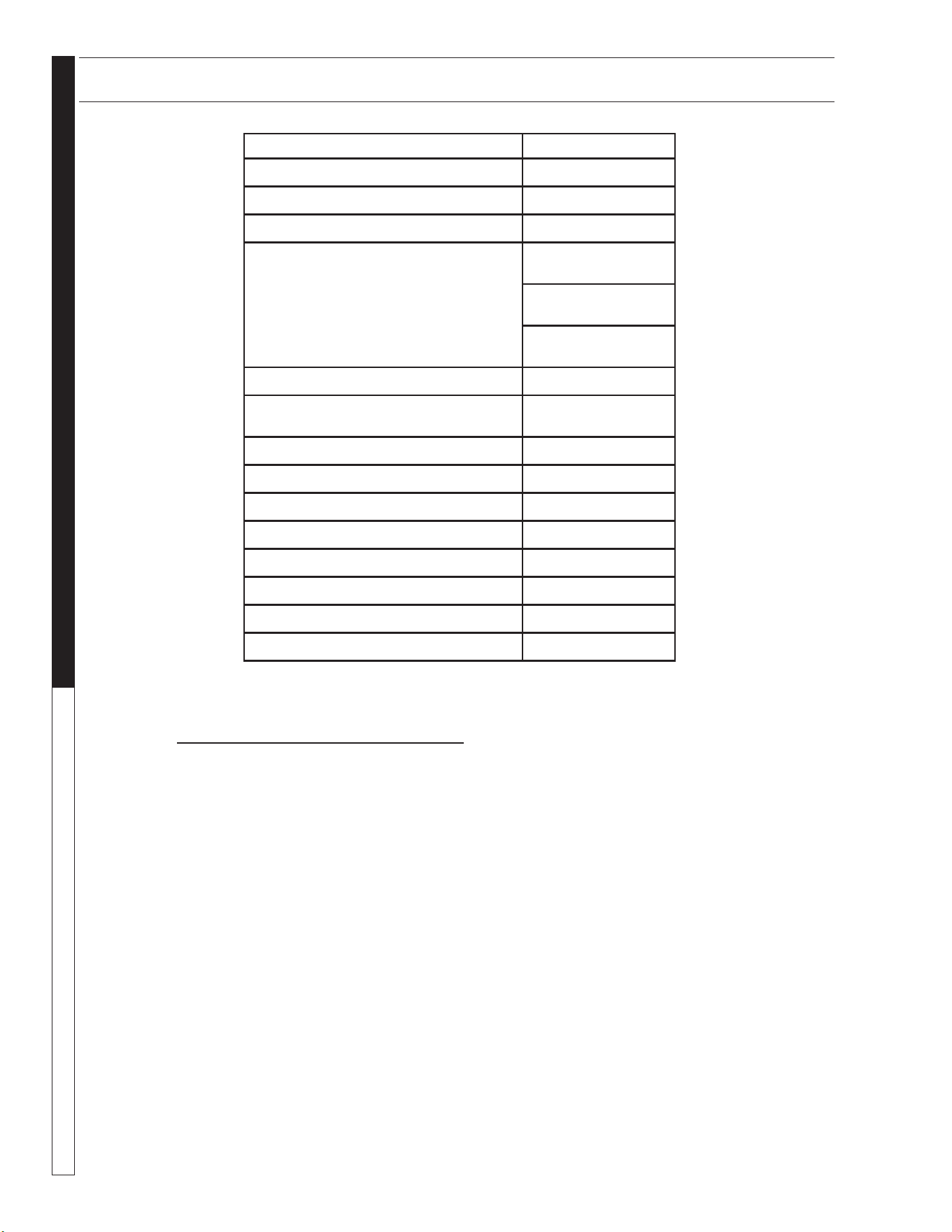
WATERMAZE CL-304 • 8.913-972.0-A
WATER TREATMENT SYSTEM
Specifications
44
SPECIFICATIONS
MODEL CL-304
MAXIMUM FLOW
5 gpm
OIL/WATER SEPARATOR CAPACITY
300 gal.
SOLIDS SEPARATION CHAMBER
Ye s
ELECTRICAL
230 Volt 1 PH
Amps 15
230 Volt 3 PH
Amps 9
460 Volt 3 PH
Amps 5
MEDIA FILTER
330 lbs.
CARTRIDGE FILTER
(1) 125 sq. ft.
10 Micron
OIL SKIMMER
Ye s
CHLORINATOR
Ye s
COALESCING PACK
94 sq. ft.
FILTERED WATER HOLDING TANK
40 gal.
ORP/pH CONTROLLER
Optional
ELECTRICAL PANEL
Ye s
DIMENSIONS (L x W x H)
72" x 72" x 90"
NET DRY WEIGHT (approx)
1545 lbs.
PART NUMBER DESCRIPTION
Water Maze Consumable Parts
9-029200 .45 x .55 mm Sand (Std. bag size -100 lbs.)
9-029300 1/4" x 1/8" Gravel (Std. bag size - 100 lbs.)
9-029600 .60 x .80 mm #1 Anthracite (Std. bag size - 50 lbs.)
9-52029 5-Way Test Strips
9-52032 pH Test Strips
CONSUMABLE PARTS LIST

WATERMAZE CL-304 • 8.913-972.0-A
45
WATER TREATMENT SYSTEM
WARRANTY
LIMITED NEW PRODUCT WARRANTY
WASH WATER / WATER TREATMENT SYSTEMS
WHAT THIS WARRANTY COVERS
All
WATER MAZE
water treatment systems are warranted by to the original purchaser to be free from defects in materials
and workmanship under normal use, for the periods specified below. This Limited Warranty, subject to the exclusions shown
below, is calculated from the date of the original purchase, and applies to the original components only. Any parts replaced
under this warranty will assume the remainder of the part’s warranty period. A 60 day grace period will be given for installa-
tion.
ONE YEAR PARTS AND 30 DAY LABOR WARRANTY:
All components excluding normal wear items as described below.
WARRANTY PROVIDED BY OTHER MANUFACTURERS:
Motors, which are warranted by their respective manufacturers, are serviced through these manufacturers’ local authorized
service centers.
WATER MAZE
cannot provide warranty on these items.
WHAT THIS WARRANTY DOES NOT COVER
This warranty does not cover the following items:
1. Normal wear items, such as seals, filters, gaskets, O-rings, packings, pistons, brushes, filtering media, ozone
bulbs, sensors, UV scanners, oil-skimmer belt, impedance sensor. Minor leaks covered first time on original start-
up only.
2. Damage or malfunctions resulting from accidents, abuse, modifications, alterations, incorrect installation, improper
servicing, failure to follow
manufacturer’s maintenance instructions, or use of the equipment beyond its stated
usage specifications as contained in the operator’s manual.
3. Damage due to freezing, sludge build-up, chemical deterioration (oxidation, chloride or fluoride corrosion), and
rust.
4. Damage to components from fluctuations in electrical or water supply.
5. Normal maintenance service, including adjustments.
6. Transportation to service center, field labor charges, or freight damage.
7. Consumables and water quality.
WHAT YOU MUST DO TO OBTAIN WARRANTY SERVICE
While not required for warranty service, we request that you register your
WATER MAZE
Product by returning the com-
pleted registration card. In order to obtain warranty service on items warranted by
WATER MAZE
, you must return the
product to your Authorized
WATER MAZE
Dealer, freight prepaid, with proof of purchase, within the applicable warranty
period. If the product is permanently installed, you must notify your Authorized
WATER MAZE
Dealer of the defect. Your
Authorized
WATER MAZE
Dealer will file a claim with
WATER MAZE
, who must subsequently verify the defect. In most
cases, the part must be returned to
WATER MAZE
freight prepaid with the claim. For warranty service on components
warranted by other manufacturer’s, your Authorized
WATER MAZE
Dealer can help you obtain warranty service through
these manufacturers’ local authorized service centers.
LIMITATION OF LIABILITY
WATER MAZE’S
liability for special, incidental, or consequential damages is expressly disclaimed. In no event shall
WATER MAZE’S
liability exceed the purchase price of the product in question.
WATER MAZE
makes every effort to ensure
that all illustrations and specifications are correct, however, these do not imply a warranty that the product is merchantable
or fit for a particular purpose, or that the product will actually conform to the illustrations and specifications. Our obligation
under this warranty is expressly limited at our option to the replacement or repair at a service facility or factory designated
by us, of such part or parts as inspection shall disclose to have been defective. THE WARRANTY CONTAINED HEREIN
IS IN LIEU OF ALL OTHER WARRANTIES, EXPRESS OR IMPLIED, INCLUDING ANY IMPLIED WARRANTY WATER
QUALITY, MERCHANTABLIITY OR FITNESS FOR A PARTICULAR PURPOSE ARE EXPRESSLY LIMITED TO THE
DURATION OF THIS WARRANTY.
This warranty gives you specific legal rights and you may also have other rights which
vary from state to state.
WATER MAZE
does not authorize any other party, including authorized
WATER MAZE
Distributors,
to make any representation or promise on behalf of
WATER MAZE
, or to modify the terms, conditions, or limitations in any
way. It is the buyer’s responsibility to ensure that the installation and use of
WATER MAZE
products conforms to local
codes. While
WATER MAZE
attempts to assure that its products meet national codes, it cannot be responsible for how the
customer chooses to use or install the product. Some states do not allow limitations or exclusion or limitation of incidental or
consequential damages, so the above limitation or exclusion may not apply to you.

Form #8.913-972.0-A • Revised 4/15 • Printed in U.S.A.